SECTION 6 4 SERVICE PROCEDURES AND SPECIFICATIONS. Electrical components
|
|
|
- Shavonne Pierce
- 5 years ago
- Views:
Transcription
1 SERVICE PROCEDURES AND SPECIFICATIONS Electrical components SECTION 6 4 Specifications Checking battery condition Battery recharging precautions Checking and replacing the blade type fuses Checking the cartridge type fuses Replacing the windshield wiper blades Adding washer fluid Checking the headlight aim Replacing light bulbs


2 ELECTRICAL COMPONENTS SPECIFICATIONS FUSES LOCATION OF FUSES Engine compartment (fuses) 206 Driver s side kick panel Driver s side kick panel (fuses)
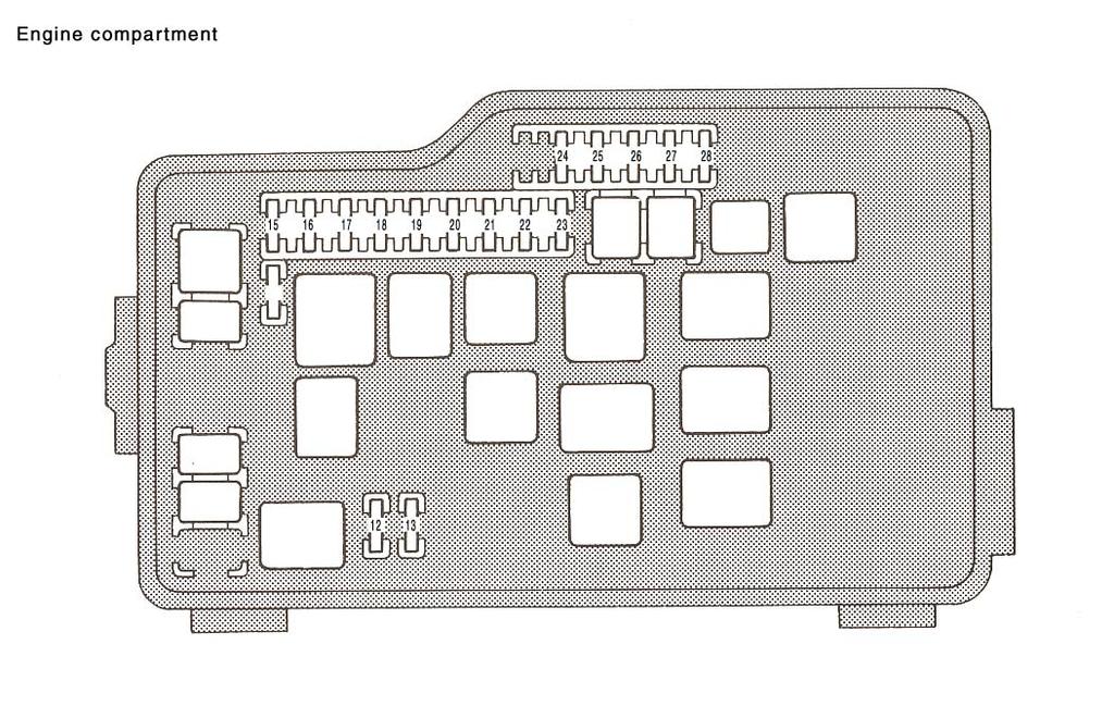
3 Engine compartment 207
4 208 NO. FUSE AMPERE CIRCUIT 1 SEAT HTR 15 Seat heater 2 STOP 20 3 GAUGE 15 4 ECU-IG 10 Shift lock system, high mounted stoplight, cruise control system, anti-lock brake system, traction control system, multiport fuel injection system / sequential multiport fuel injection system, stop lights Rear window and outside rear view mirror defogger, heater control system, air conditioning system, gauges and meters, service reminder indicators and warning buzzers (except discharge and open door warning lights), charging system, automatic transmission indicator, back-up lights, daytime running light system Shift lock system, telephone, power door lock system for passenger seat, seat belt system, anti-lock brake system, power steering control system, traction control system, cruise control system, driving pattern selector switch, tilt and telescopic control system, power antenna, electronic cooling fan system, instrument panel lights, automatic light control system, power door lock control system NO. FUSE AMPERE CIRCUIT 5 CIG 15 Clock, air conditioning system, radio, cassette tape player, compact disc player, shift lock system, SRS, front and rear cigarette lighters, power door lock control system, power rear view mirror control system 6 TURN 10 Turn signal lights and indicator 7 WIPER 15 8 PANEL SRS 7.5 SRS 10 TAIL 10 Windshield wipers and washer, headlight cleaner Automatic transmission indicator, heater control system, emergency flasher switch, glovebox light, rear ashtrays, clock, front cigarette lighter light, radio, cassette tape player, compact disc player, driving pattern selector switch light, instrument panel lights, daytime running lights system License plate lights, parking lights, tail lights
5 NO. FUSE AMPERE CIRCUIT 11 MIR HTR 10 Outside rear view mirror defogger 12 FOG 15 Fob lights 13 DRL 7.5 Vehicles sold in Canada Daytime running light system 14 TRAC 10 Traction control system 15 DOME ECU-B ALT SENSING Interior light, vanity lights, electric moon roof system, cruise control system, open door warning light, personal lights, trunk room light, door courtesy lights, footlights, ignition switch light, clock, anti-lock brake system, power antenna Locking with wireless remote control system, anti-lock brake system, traction control system, cruise control system, daytime running light system 7.5 Charging system NO. FUSE AMPERE CIRCUIT 18 AM TEL 15 Telephone Multiport fuel injection system / sequential multiport fuel injection system, SRS, charging lamp, starting system, electronic ignition system / distributor ignition system, gauges and meters, service reminder indicators and warning buzzers (except discharge and open door warning lights) 20 HAZ. HORN 20 Emergency flashers, horns 21 EFI RADIO NO IG2 30 Electronically controlled automatic transmission system, multiport fuel injection system / sequential multiport fuel injection system Radio, cassette tape player, compact disc player, power antenna Electronic ignition system / distributor ignition system 209
6 NO. FUSE AMPERE CIRCUIT HEAD RH 15 HEAD RH-UPR 10 HEAD LH 15 HEAD LH-UPR HEAD RH-LWR HEAD LH-LWR Vehicles sold in U.S.A. Right hand headlight Vehicles sold in Canada Right-hand headlight (high beam) Vehicles sold in U.S.A. Left-hand headlight Vehicles sold in Canada Left-hand headlight (high beam) Vehicles sold in Canada Right-hand headlight (low beam) Vehicles sold in Canada Left-hand headlight (low beam) 28 RDI FAN 30 Electronic cooling fan system CHECKING BATTERY CONDITION CAUTION: BATTERY PRECAUTIONS The battery produces a flammable and explosive hydrogen gas. Do not cause a spark by contacting the battery terminals with tools. Do not smoke or light a match near the battery. The electrolyte contains poisonous and corrosive sulfuric acid. Avoid contact with eyes, skin or clothes. Never inhale or swallow electrolyte. Wear protective safety glasses when working near the battery. Keep children away from the battery. EMERGENCY MEASURES If electrolyte gets in your eyes, flush your eyes with clean water for at least 15 minutes and get immediate medical attention. If possible, continue to apply water with a sponge or cloth while en route to the medical office. If electrolyte gets on your skin, thoroughly wash the contacted area. If you feel a pain or burn, get medical attention immediately. 210


7 If electrolyte gets on your clothes, there is a possibility of its soaking through to your skin, so immediately take off the exposed clothing and follow the procedure above, if necessary. If you happen to swallow electrolyte, drink a large quantity of water or milk. Follow with milk of magnesia, beaten raw egg or vegetable oil. Then go immediately for emergency help. Terminals Be sure the engine and all accessories are turned off before performing maintenance. Remove the ground cable first and reinstall it last. Be careful not to cause a short circuit with tools. Take care no solution gets into the battery when washing it. Blue Red White Hold-down clamp 1. Check the battery for corroded or loose connections, cracks, or loose hold-down clamps. a. If the battery is corroded, wash it off with a solution of warm water and baking soda. Coat the terminals with grease to prevent further corrosion. b. If the connections are loose, tighten the clamp bolts but do not overtighten. c. Tighten the hold-down clamp only enough to keep the battery firmly in place. Overtightening may damage the battery case. 2. Check the hydrometer as shown. BLUE Good conditions. WHITE Charging necessary. Have the battery checked by your Lexus dealer. RED Have the battery checked by your Lexus dealer. 211
8 Your Lexus has a maintenance free battery. Do not refill the battery with water. Use a cover on the battery for longer life. BATTERY RECHARGING PRECAUTIONS During recharging, the battery is producing hydrogen gas. Therefore, before recharging: 1. If recharging with the battery installed on the vehicle, be sure to disconnect the ground cable. 2. Be sure the power switch on the recharger is off when connecting the charger cables to the battery and when disconnecting them. CAUTION: Always charge the battery in an unconfined area. Do not charge the battery in a garage or closed room where there is not sufficient ventilation. Only do a slow charge (5A or less). Charging at a quicker rate is dangerous. Never recharge the battery while the engine is running. Also, be sure all accessories are turned off. 212


9 CHECKING AND REPLACING THE BLADE TYPE FUSES Determine which fuse may be causing the problem. The lid of the fuse box shows the name of the circuit for each fuse. Driver s side kick panel Engine compartment Spare fuses Pull-out tool 2. Make sure the inoperative component is turned off. Pull the suspected fuse straight out with the pull-out tool and check it. If it has blown, push a new fuse into the clips. a. Look carefully at the fuse. If the thin wire is broken, the fuse has blown. If you are not sure or if it is too dark to see, try replacing the suspected fuse with one of the same value that you know is good. b. Install only a fuse with the amperage rating designated on the fuse box lid. 1. Turn the ignition switch off and open the fuse box lid. 213


10 CHECKING THE CARTRIDGE TYPE FUSES Driver s side kick panel Good Blown 214 If you do not have a spare fuse, in an emergency you can pull out the CIG, RADIO NO. 1, DOME or SEAT HTR fuse, which may be dispensable for normal driving, and use it if its amperage rating is the same. If you cannot use one of the same amperage, use one lower than, but as close as possible to, the amperage. If the amperage is lower than that specified, the fuse might blow out again but this does not indicate anything wrong. Be sure to get the correct fuse as soon as possible and return the substitute to its original clips. It is a good idea to purchase a set of spare fuses and keep them in your vehicle for emergencies. If the new fuse immediately blows out, there is a problem with the electrical system. Have your Lexus dealer correct it as soon as possible. CAUTION: Never use a fuse with a higher amperage rating, or another object, in place of a fuse. This may cause extensive damage and possibly a fire. Engine compartment If the headlights or other electrical components do not work and the blade type fuses are O.K., check the cartridge type fuses. If any of the cartridge type fuses are melted, they must be replaced.


11 Type A Good Type B Good REPLACING THE WINDSHIELD WIPER BLADES When the wiper no longer cleans adequately, the wiper blades may be worn or cracked requiring replacement. Before replacement Blown Blown If there is an overload in the circuits from the battery, the fuses are designed to melt before the entire wiring harness is damaged. Before replacing the fuses, have the cause of electrical overload determined and repaired by your Lexus dealer. CAUTION: Always use a genuine Lexus fuse or equivalent for replacement. Never install an ordinary wire even for a temporary fix. This may cause extensive damage and possibly a fire. Rest position Retracted positionf Make sure whether the wiper blades are at the rest position or at the retracted position. If at the rest position--- Swing the wiper arm away from the windshield until it stands up. 215


12 If at the retracted position Change the position of the wiper blade to the rest position above the hood level. See page 17 for changing the wiper blade position. 2. Swing the wiper arm away from the windshield until it stands up. Do not replace the wiper blade at the retracted position as it may damage your vehicle s paint. Replacement of rubber Insert from below Protrusion Cutout 3. To install a new rubber, insert the end with small protrusion from the lower end of the blade frame, and work the rubber along up to the end of the blade frame. 4. Once all of the rubber is in the blade frame, make sure the end of the blade frame is inserted in the cutout of the rubber. Pull downward Be careful not to scratch the glass surface with the wiper frame. Cutout 1. Pull the end of the rubber downward until the cutout of the rubber is free of the blade frame. 2. Pull the rubber blade out the blade frame. 216


13 Replacement of wiper blade Clip 1. Push the clip to release the lock joining the wiper arm and blade. 2. Slide the wiper blade downward to separate it from the wiper arm. 3. Remove the wiper blade. 4. Install a new wiper blade to the wiper arm. 5. Slide the wiper blade upward fully until it locks. 6. Return the wiper blade and arm. Be careful not to scratch the glass surface with the wiper frame. 217


14 ADDING WASHER FLUID CHECKING THE HEADLIGHT AIM Beam angle gauge (vertical movement) Beam angle gauge (horizontal movement) If the washer tank becomes nearly empty, add washer fluid. You may use plain water as washer fluid. However, in cold areas where temperatures range below the freezing point, use washer fluid containing antifreeze. This product is available at your Lexus dealer and most auto parts stores. Follow the manufacturer s directions for how much to mix with water. Do not use engine antifreeze or any other substitute because it may damage your vehicle s paint. Before checking the headlight aim: 1. Be sure that the body around the headlight is not deformed. 2. Park the vehicle on a level spot. 3. The driver gets into the driver s seat and puts the vehicle in a state readying for a driving (with a full tank). 4. Bounce the vehicle several times. 218
 2.")

15 Beam angle gauge (vertical movement) Acceptable range Bubble To check the headlight aim, check the vertical and horizontal gauges. 1. Look at the beam angle gauge (vertical movement). The bubble of the gauge should not deviate from the center of the gauge by more than four marks to either side of the gauge. Beam angle gauge (horizontal movement) 2. Look at the beam angle gauge (horizontal movement). The red mark should not deviate by more than one mark to either side of the gauge. If the error is over the value specified above, take the vehicle to your Lexus dealer to adjust the headlight aim. REPLACING LIGHT BULBS The illustration on the following pages show the locations of light bulbs. If it is necessary to replace a bulb, take your vehicle to your Lexus dealer as soon as possible. Use bulbs with the bulb numbers and wattage ratings given in the table. The single end bulbs are removed by pressing them in and turning counterclockwise. Double-end bulbs (*) or wedge base bulbs (**) pull straight out of the holder clips. Only use a bulb of the listed type. Acceptable range Mark 219
 9006 55 Headlights (high beam) 9005 65 Fog lights H3 55 Front turn signal and parking lights 1157 NA 27/8 Rear turn signal lights 1156 27 Stop and tail lights 1157")
16 Light Bulbs Bulb No. W Headlights (low and high beam) Headlights (high beam) Fog lights H3 55 Front turn signal and parking lights 1157 NA 27/8 Rear turn signal lights Stop and tail lights / 8 Back-up lights License plate lights** 5 Rear side marker lights / 8 Interior light with moon roof* without moon roof Front personal lights 8 Rear personal lights* 3 Glovebox light** 1.2 Door courtesy lights** Footlights** 1.4 Vanity lights* 3 Trunk room light** LIGHT LOCATION Headlights Fog lights Parking and front turn signal lights 220


17 ELECTRICAL COMPONENTS Front personal light Interior light Rear personal light Vanity light Glovebox light Footlights Door courtesy lights Trunk room light License plate lights Rear turn signal, stop and tail, rear side marker and back-up lights 221
SECTION 6 4 SERVICE PROCEDURES AND SPECIFICATIONS. Electrical components
 SERVICE PROCEDURES AND SPECIFICATIONS Electrical components SECTION 6 4 Specifications........................................... 214 Checking battery condition................................ 218 Battery
SECTION 6 4 SERVICE PROCEDURES AND SPECIFICATIONS. Electrical components
 SERVICE PROCEDURES AND SPECIFICATIONS Electrical components SECTION 6 4 Specifications........................................... 190 Checking battery condition and fluid level................... 194 Battery
SECTION 6 4 SERVICE PROCEDURES AND SPECIFICATIONS. Electrical components
 SERVICE PROCEDURES AND SPECIFICATIONS Electrical components SECTION 6 4 Specifications........................................... 220 Checking battery condition................................ 224 Battery
SECTION 6 4 SERVICE PROCEDURES AND SPECIFICATIONS. Electrical components
 SERVICE PROCEDURES AND SPECIFICATIONS Electrical components SECTION 6 4 Specifications........................................... 214 Checking battery condition and fluid level................... 218 Battery
SECTION 6 4 SERVICE PROCEDURES AND SPECIFICATIONS. Electrical components
 SERVICE PROCEDURES AND SPECIFICATIONS Electrical components SECTION 6 4 Specifications........................................... 194 Checking battery condition and fluid level................... 198 Battery
SECTION 6 4 SERVICE PROCEDURES AND SPECIFICATIONS. Electrical components
 SERVICE PROCEDURES AND SPECIFICATIONS Electrical components SECTION 6 4 Specifications..................................................................... 554 Checking battery condition..........................................................
SECTION 7 3 DO IT YOURSELF MAINTENANCE MR2 U. Electrical components
 DO IT YOURSELF MAINTENANCE Electrical components SECTION 7 3 Checking battery condition.................................. 178 Battery recharging precautions............................... 179 Checking
Part 8 Dimensions and weight Engine SPECIFICATIONS
 Part 8 Dimensions and weight Engine SPECIFICATIONS Dimensions and weight Engine Fuel Service specifications Tires Fuses Overall length mm (in.) 4515 (177.7) Overall width mm (in.) 1810 ( 71.3) Overall
Part 8 SPECIFICATIONS
 Part 8 SPECIFICATIONS Dimensions and weight Engine Fuel Service specifications Tires Fuses Dimensions and weight P195/70R 14 tire Overall length 4783 (188.3) Overall width 1780 (70.1) Overall height 1416
SECTION 8 SPECIFICATIONS. 06Camry_U (L/O 0507) Specifications. Dimensions and weights Service specifications
 Specifications. Dimensions and weights Service specifications") SPECIFICATIONS SECTION 8 Specifications Dimensions and weights.................................... 336 Engine.................................................... 336 Fuel.......................................................
SPECIFICATIONS SECTION 8 Specifications Dimensions and weights.................................... 336 Engine.................................................... 336 Fuel.......................................................
SECTION 8 SPECIFICATIONS. Dimensions Service specifications
 SPECIFICATIONS SECTION 8 Dimensions... 342 Engine... 342 Fuel... 342 Service specifications... 343 Tires... 346 Fuses... 347 341 Dimensions Engine Fuel Overall length mm (in.) 4825 (190.0) Overall width
MR2 U SECTION 8 SPECIFICATIONS. Dimensions and weight Service specifications MR2 (OM17475U)
") SPECIFICATIONS SECTION 8 Dimensions and weight...................................... 192 Engine.................................................... 192 Fuel.......................................................
SPECIFICATIONS SECTION 8 Dimensions and weight...................................... 192 Engine.................................................... 192 Fuel.......................................................
SECTION 8 SPECIFICATIONS 05 HIGHLANDER_U (L/O 0409) Specifications. Dimensions and weights Service specifications
 Specifications. Dimensions and weights Service specifications") SPECIFICATIONS SECTION 8 Specifications Dimensions and weights.................................... 406 Engine.................................................... 406 Fuel.......................................................
SPECIFICATIONS SECTION 8 Specifications Dimensions and weights.................................... 406 Engine.................................................... 406 Fuel.......................................................
Light condition and operation Windshield glass condition Wiper blade condition Paint condition and corrosion Fluid leaks Door and hood lock condition
 GENERAL CHECKS Engine Compartment The following should be checked regularly: Engine oil level and condition Transmission fluid level and condition Brake fluid level Clutch fluid level Engine coolant level
POWER SOURCE (Current Flow Chart)
") The chart below shows the route by which current flows from the battery to each electrical source (Fusible Link, Circuit Breaker, Fuse, etc.) and other parts. The next page and following pages show the
The chart below shows the route by which current flows from the battery to each electrical source (Fusible Link, Circuit Breaker, Fuse, etc.) and other parts. The next page and following pages show the
SECTION 1 2 INSTRUMENTS AND CONTROLS. Switches
 SECTION 1 2 INSTRUMENTS AND CONTROLS Switches Headlight and turn signal switch............................ 16 Fog light switch........................................... 17 Windshield wiper and washer
POWER SOURCE (Current Flow Chart)
") POWER SOURCE (Current Flow Chart) The chart below shows the route by which current flows from the battery to each electrical source (Fusible Link, Circuit Breaker, Fuse, etc.) and other parts. The next
POWER SOURCE (Current Flow Chart) The chart below shows the route by which current flows from the battery to each electrical source (Fusible Link, Circuit Breaker, Fuse, etc.) and other parts. The next
Do-it-yourself service precautions
 Do-it-yourself service precautions If you perform maintenance yourself, be sure to follow the correct procedures as given in these sections. Items Battery condition ( P. 321) Brake fluid level ( P. 318)
Do-it-yourself service precautions
 Do-it-yourself service precautions If you perform maintenance yourself, be sure to follow the correct procedure given in these sections. Items Battery condition ( P. 518) Brake fluid level ( P. 516) Parts
J POWER SOURCE (Current Flow Chart)
") J POWER SOURCE (Current Flow Chart) 374 J 375 J POWER SOURCE (Current Flow Chart) Driver Side J/B (See Page 26) 7.5A ECU ACC Automatic Air Conditioning (Front) Automatic Light Control Back Door Opener
J POWER SOURCE (Current Flow Chart) 374 J 375 J POWER SOURCE (Current Flow Chart) Driver Side J/B (See Page 26) 7.5A ECU ACC Automatic Air Conditioning (Front) Automatic Light Control Back Door Opener
Do-it-yourself service precautions
 Do-it-yourself service precautions If you perform maintenance yourself, be sure to follow the correct procedure given in these sections. Items Battery condition ( P. 318) Brake fluid level ( P. 315) Engine
ARTICLE BEGINNING FUSES & CIRCUIT BREAKERS * PLEASE READ FIRST * ALL BUT JETTA ( ) Fuses & Circuit Breakers Volkswagen ELECTRICAL
 Fuses & Circuit Breakers Volkswagen ELECTRICAL") Article Text ARTICLE BEGINNING Fuses & Circuit Breakers 1987-96 Volkswagen ELECTRICAL FUSES & CIRCUIT BREAKERS * PLEASE READ FIRST * The fuse panel is located under the left side of the dash board by the
Article Text ARTICLE BEGINNING Fuses & Circuit Breakers 1987-96 Volkswagen ELECTRICAL FUSES & CIRCUIT BREAKERS * PLEASE READ FIRST * The fuse panel is located under the left side of the dash board by the
Do-it-yourself service precautions
 Do-it-yourself service precautions If you perform maintenance yourself, be sure to follow the correct procedure given in these sections. Items Battery condition ( P. 457) Brake fluid level ( P. 455) Engine
Index. Abbreviation list Alphabetical index What to do if
 Index Abbreviation list... 478 Alphabetical index... 479 What to do if...... 489 477 Abbreviation list Abbreviation/Acronym list ABBREVIATIONS ABS ACC ALR CRS DISP ECU EDR ELR GAWR GVWR I/M LATCH LED LSD
Index. Abbreviation list Alphabetical index What to do if
 Index Abbreviation list... 470 Alphabetical index... 471 What to do if...... 481 469 Abbreviation list Abbreviation/Acronym list ABBREVIATIONS ABS ACC ALR CRS DISP ECU EDR ELR GAWR GVWR I/M LATCH LED LSD
(1,1) Index 14 北米Model "A1330BE-B" EDITED: 2017/ 11/ 30
 Index 14 北米Model A1330BE-B EDITED: 2017/ 11/ 30") Index 14 14-2 Index A Abbreviation... 3 ABS (Anti-lock Brake System)... 7-33 Warning light... 3-20 Access key fob... 2-3 Warning light... 3-25 Accessories... 11-37 Accessory power outlet... 6-7 Air cleaner
Index 14 14-2 Index A Abbreviation... 3 ABS (Anti-lock Brake System)... 7-33 Warning light... 3-20 Access key fob... 2-3 Warning light... 3-25 Accessories... 11-37 Accessory power outlet... 6-7 Air cleaner
Position of Parts in Engine Compartment
 ELECTRICAL WIRING ROUTING [5S FE] Position of Parts in Engine Compartment A 1 A/C Ambient Temp. Sensor D 1 Distributor A 2 A/C Condenser Fan Motor A 3 A/C Idle Up VSV E 1 ECT Solenoid A 4 A/C Magnet Clutch
Position of Parts in Engine Compartment
 [1UZ FE] Position of Parts in Engine Compartment A 1 A/C Ambient Temp. Sensor E 4 Engine Coolant Temp. Sensor (Water Temp. Sensor A 2 A/C Dual Pressure SW and A/C High Pressure SW (for Cooling Fan)) A
Do-it-yourself service precautions
 Do-it-yourself service precautions If you perform maintenance yourself, be sure to follow the correct procedure given in these sections. Items 12 volt battery condition ( P. 428) Engine/power control unit
SECTION 1 2 INSTRUMENTS AND CONTROLS. Switches
 SECTION 1 2 INSTRUMENTS AND CONTROLS Switches Headlight switch 16 Headlight dimmer and turn signal switch 17 Fog light switch 18 Windshield wiper and washer switch 19 Rear window and outside rear view
Do-it-yourself service precautions
 Do-it-yourself service precautions If you perform maintenance yourself, be sure to follow the correct procedures as given in these sections. Items Battery condition ( P. 543) Brake fluid level ( P. 540)
SECTION 7 1 DO IT YOURSELF MAINTENANCE MR2 U. Introduction
 SECTION 7 1 DO IT YOURSELF MAINTENANCE Introduction Engine compartment overview............................... 160 Trunk room overview........................................ 161 Fuse locations.............................................
G ELECTRICAL WIRING ROUTING [1MZ-FE] Position of Parts in Engine Compartment
![G ELECTRICAL WIRING ROUTING [1MZ-FE] Position of Parts in Engine Compartment](/thumbs/87/97394184.jpg "G ELECTRICAL WIRING ROUTING [1MZ-FE] Position of Parts in Engine Compartment") G ELECTRICAL WIRING ROUTING [1MZ-FE] Position of Parts in Engine Compartment A 1 A/C Ambient Temp. Sensor A 2 A/C Condenser Fan Motor A 3 A/C Magnetic Clutch and Lock Sensor A 4 A/C Triple Pressure SW
G ELECTRICAL WIRING ROUTING [1MZ-FE] Position of Parts in Engine Compartment A 1 A/C Ambient Temp. Sensor A 2 A/C Condenser Fan Motor A 3 A/C Magnetic Clutch and Lock Sensor A 4 A/C Triple Pressure SW
Position of Parts in Engine Compartment
 ELECTRICAL WIRING ROUTING [3S GTE] Position of Parts in Engine Compartment A 1 A/C Ambient Temp. Sensor D 1 Date Link Connector 1 (Check Connector) A 2 A/C Condenser Fan Motor D 2 Distributor A 4 A/C Magnetic
Model: OBD-L On-Board-Diagnostics II Memory Saver Detector
 Model: OBD-L On-Board-Diagnostics II Memory Saver Detector OWNERS MANUAL IMPORTANT SAFETY INSTRUCTIONS SAVE THESE INSTRUCTIONS This manual will show you how to use your memory saver detector safely and
SECTION 1 2 INSTRUMENTS AND CONTROLS. Switches
 SECTION 1 2 INSTRUMENTS AND CONTROLS Switches Headlight switch.......................................... 16 Headlight dimmer and turn signal switch..................... 17 Fog light switch...........................................
Part 1 OPERATION OF INSTRUMENTS AND CONTROLS
 Part 1 OPERATION OF INSTRUMENTS AND CONTROLS Chapter 1-4 Lights, Wipers and Defogger Headlights and turn signals Emergency flashers Instrument panel light control Front fog lights Interior lights Ignition
G ELECTRICAL WIRING ROUTING
 2 6 G ELECTRICAL WIRING ROUTING Position of Parts in Engine Compartment A1 A/C Front Magnetic Valve A3 A/C Magnetic Clutch A6 A/T Flud Temp. Sensor A7 ABS Actuator A8 ABS Actuator A10 ABS Speed Sensor
RoaDCharger 20 Amp 7 Way Installation Manual
 RoaDCharger 20 Amp 7 Way Installation Manual Safety First This symbol is used to call attention to instructions concerning personal safety. Be sure to observe and follow these instructions. Take time to
Changing light bulbs. Introduction WARNING
 Changing light bulbs Introduction In this section you ll find information about: Indicator light Information on light bulb replacement Changing headlight bulbs Changing the fog light bulbs in the front
FUSES & CIRCUIT BREAKERS
 FUSES & CIRCUIT BREAKERS FUSES & CIRCUIT BREAKERS 1989-95 FUSES & CIRCUIT BREAKERS Ford Motor Co. INTERIOR FUSE PANEL IDENTIFICATION (1983-88 MODELS) On all models, the fuse panel is located under the
CIRCUIT DIAGRAMS GROUP CONTENTS HOW TO READ CIRCUIT DIAGRAMS VANITY MIRROR LIGHT JUNCTION BLOCK...
 90-1 GROUP 90 CONTENTS HOW TO READ................................. 90-4 JUNCTION BLOCK.............. 90-10 JOINT CONNECTOR............. 90-12 CENTRALIZED JUNCTION........ 90-13 POWER DISTRIBUTION SYSTEM..
Black plate (27,1) Index 14 北米Model "A3180BE-B" EDITED: 2014/ 2/ 7
 Index 14 北米Model A3180BE-B EDITED: 2014/ 2/ 7") Index 14 14-2 Index A Abbreviation... 3 ABS (Anti-lock Brake System)... 7-20 Warning light... 3-15, 7-21 Accessories... 5-2, 11-36 Accessory power outlet... 6-10 Active head restraint... 1-6 Air cleaner
Index 14 14-2 Index A Abbreviation... 3 ABS (Anti-lock Brake System)... 7-20 Warning light... 3-15, 7-21 Accessories... 5-2, 11-36 Accessory power outlet... 6-10 Active head restraint... 1-6 Air cleaner
12-2. Specifications. & Dimensions. These specifications are subject to change without notice. Specifications/Specifications.
 Specifications Specifications... 12-2 Dimensions... 12-2 Engine... 12-3 Fuel... 12-3 Engine oil... 12-4 Manual transmission, front differential and rear differential gear oil... 12-6 Fluids... 12-7 Engine
Fuse/Relay Information
 /Relay Information Under-dash /Relay Box C901 (To turn signal/hazard relay) C902 (To blower motor relay) C903 (To rear window defogger relay) C405 C404 C904 (To integrated control unit) C602 (To dashboard
G ELECTRICAL WIRING ROUTING
 G ELECTRICAL WIRING ROUTING Position of Parts in Engine Compartment A 1 A/C Condenser Fan Motor A 2 A/C Magnetic Clutch and Lock Sensor A 3 A/C Triple Pressure SW (A/C Dual and Single Pressure SW) A 4
G ELECTRICAL WIRING ROUTING
 2 6 G ELECTRICAL WIRING ROUTING [2JZ-GTE] Position of Parts in Engine Compartment A 1 A/C Ambient Temp Sensor A 2 A/C Condensor Fan Motor A 3 A/C Triple Pressure SW (A/C Dual and Single Pressure SW) A
L PART NUMBER OF CONNECTORS
 L PART NUMBER OF CONNECTORS Code Part Name Part Number Code Part Name Part Number A 1 A/C Ambient Temp. Sensor 90980-11070 B15 Blower Motor Controller (Rear) 90980-11136 A 2 A/C Magnetic Clutch 90980-11271
Fuse/Relay Information
 BD 10/24/91 kd 11/12 smk 11/14/91 MC 4/8/92 bd 4/14/92 92 PRELUDE /Relay Information Under-hood /Relay Box 47 46 45 44 43 42 41 40 39 31 49 48 51 50 37 36 35 34 33 32 C941 (To ABS motor relay) 38 C942
SECTION 8 1 DO IT YOURSELF MAINTENANCE. Introduction
 SECTION 8 1 DO IT YOURSELF MAINTENANCE Introduction Engine compartment overview............................... 396 Fuse locations............................................. 397 Do it yourself service
SECTION 8 1 DO IT YOURSELF MAINTENANCE. Introduction
 SECTION 8 1 DO IT YOURSELF MAINTENANCE Introduction Motor compartment overview................................ 176 Fuse locations............................................. 177 Do it yourself service
17. BATTERY/CHARGING SYSTEM
 17 17 BATTERY/CHARGING SYSTEM CHARGING SYSTEM LAYOUT/CHARGING CIRCUIT ----------- 17-1 SERVICE INFORMATION------------------------------------------------ 17-2 TROUBLESHOOTING-----------------------------------------------------
CONFIGURATION DIAGRAMS
 80-1 GROUP 80 CONFIGURATION DIAGRAMS CONTENTS CONFIGURATION DIAGRAMS......................... 80A SPLICE LOCATIONS................................. 80B 80A-2 GROUP 80A CONFIGURATION DIAGRAMS CONTENTS OVERALL
G ELECTRICAL WIRING ROUTING
 G ELECTRICAL WIRING ROUTING Position of Parts in Engine Compartment A 1 A/C Condenser Fan Motor A 2 A/C Magnetic Clutch and Lock Sensor A 3 A/C Triple Pressure SW (A/C Dual and Signal Pressure SW) A 4
SECTION 6 1 SERVICE PROCEDURES AND SPECIFICATIONS. Introduction
 SERVICE PROCEDURES AND SPECIFICATIONS Introduction SECTION 6 1 Vehicle identification...................................... 192 Engine compartment overview............................. 193 Do it yourself
2012 Chevrolet Volt Chevrolet Volt Owner Manual Document ID:
 xtooltipelement Service Information 2012 Chevrolet Volt Chevrolet Volt Owner Manual Document ID: 2263658 Jump Starting Jump starting is connecting jumper cables between the two vehicles to enable vehicle
MAINTENANCE INFORMATION
 MAINTENANCE INFORMATION 1992 Subaru SVX 1992-96 MAINTENANCE Subaru Maintenance Information SVX * PLEASE READ THIS FIRST * NOTE: For scheduled maintenance intervals and the related fluid capacities, fluid
SECTION 6 1 SERVICE PROCEDURES AND SPECIFICATIONS. Introduction
 SERVICE PROCEDURES AND SPECIFICATIONS Introduction SECTION 6 1 Vehicle identification...................................... 156 Engine compartment overview............................. 157 Do-it-yourself
JOHN DEERE WORLDWIDE COMMERCIAL & CONSUMER EQUIPMENT DIVISION. Lawn Tractors L100, L110, L120, and L130 TM2026 DECEMBER 2002 TECHNICAL MANUAL
 2026 December 2002 JOHN DEERE WORLDWIDE COMMERCIAL & CONSUMER EQUIPMENT DIVISION Lawn Tractors L100, L110, L120, and L130 TM2026 DECEMBER 2002 TECHNICAL MANUAL North American Version Litho in U.S.A. SAFETY
SECTION 1 3 INSTRUMENTS AND CONTROLS. Gauges, meters and service reminder indicators
 SECTION 1 3 INSTRUMENTS AND CONTROLS Gauges, meters and service reminder indicators Fuel gauge............................................... 26 Engine coolant temperature gauge..........................
LAMPS 8L - 1 LAMPS CONTENTS
 TJ LAMPS 8L - 1 LAMPS CONTENTS BULB APPLICATION... 16 HEADLAMP ALIGNMENT... 5 LAMP BULB SERVICE... 8 LAMP DIAGNOSIS... 1 LAMP SERVICE... 11 LAMP SYSTEMS... 15 LAMP DIAGNOSIS INDEX GENERAL INFORMATION GENERAL
SECTION 1 3 INSTRUMENTS AND CONTROLS. Gauges, meters and warning lights
 SECTION 1 3 INSTRUMENTS AND CONTROLS Gauges, meters and warning lights Fuel gauge............................................... 22 Engine temperature gauge................................. 22 Tachometer..............................................
9-2 In case of emergency
 In case of emergency If you park your vehicle in case of an emergency... 9-2 Temporary spare tire... 9-2 Maintenance tools... 9-3 Flat tires... 9-5 Changing a flat tire... 9-5 Tire pressure monitoring
Symptom Suspected Area See page Ignition switch is not set to each position. 11.Ignition switch BE 14
 BE2 BODY ELECTRICAL PROBLEM SYMPTOMS TABLE IGNITION SWITCH AND KEY UNLOCK WARNING SWITCH BE0ON18 Ignition switch is not set to each position. 11.Ignition switch BE14 Key unlock warning system does not
2003 RX300 from Aug. 02 Prod. (OM48442U)
") Congratulations on your selection of this Lexus. In Lexus vehicles we have invested all our engineering and design resources; all the know how we have gained in over 60 years of making automobiles; the
Congratulations on your selection of this Lexus. In Lexus vehicles we have invested all our engineering and design resources; all the know how we have gained in over 60 years of making automobiles; the
JOHN DEERE WORLDWIDE COMMERCIAL & CONSUMER EQUIPMENT DIVISION. Lawn Tractors L100, L110, L120, and L130 TM2026 DECEMBER 2002 TECHNICAL MANUAL
 2026 December 2002 JOHN DEERE WORLDWIDE COMMERCIAL & CONSUMER EQUIPMENT DIVISION Lawn Tractors L100, L110, L120, and L130 TM2026 DECEMBER 2002 TECHNICAL MANUAL North American Version Litho in U.S.A. Safety
OPERATOR S MANUAL JUMP STARTER. and DC Power Source. Model No CAUTION: Sears, Roebuck and Co., Hoffman Estates, IL U.S.A.
 OPERATOR S MANUAL JUMP STARTER and DC Power Source Model No. 71489 CAUTION: Read and follow all Safety Rules and Operating Instructions before Every Use of this Product. SAVE THESE INSTRUCTIONS. Sears,
Set-up Instructions BA49 ATV
 Set-up Instructions BA49 ATV Removal from crate 1. Remove cardboard carton from metal frame. 2. Remove metal crate. REVA 080707 Parts and Hardware Side panel hardware Handlebar cover Front bumper Left
Position of Parts in Engine Compartment
 ELECTRICAL WIRING ROUTING [5S FE] Position of Parts in Engine Compartment A 1 A/C Condenser Fan Motor E 4 Engine Coolant Temp. Sensor (EFI Water Temp. A 2 A/C Magnetic Clutch and Lock Sensor Sensor) A
SERVICE INFORMATION BATTERY/CHARGING SYSTEM XL CHARGING SYSTEM INSPECTION 15-5 REGULATOR/RECTIFIER 15-6 ALTERNATOR 15-7
 15. BATTERY/CHARGING SYSTEM SERVICE INFORMATION 15-1 TROUBLESHOOTING 15-2 BATTERY 15-3 CHARGING SYSTEM INSPECTION 15-5 REGULATOR/RECTIFIER 15-6 ALTERNATOR 15-7 SERVICE INFORMATION GENERAL t The battery
Do-it-yourself service precautions
 420-3. Do-it-yourself maintenance Do-it-yourself service precautions If you perform maintenance by yourself, be sure to follow the correct procedure as given in these sections. Items Battery condition
Symptom Suspect Area See page. 11.Ignition Switch 12.Power Source Circuit. Symptom Suspect Area See page
 BE2 PROBLEM SYMPTOMS TABLE IGNITION SWITCH: BE18204 Ignition switch is not set to each position. KEY UNLOCK WARNING SWITCH: 11.Ignition Switch 12.Power Source Circuit BE15 Key unlock warning system does
1.CONTENTS 1. Contents Control location Before riding Safe riding Driving Use genuine spare parts Use
 1.CONTENTS 1. Contents... 1 2. Control location... 3 3. Before riding... 4 4. Safe riding... 4 5. Driving... 5 6. Use genuine spare parts... 5 7. Use of each component... 6 Gauges... 6 Operation of ignition
WIRING DIAGRAM 1. General Description
 Page 1. General Description...1 2. Wiring Diagram...10 (1) POWER SUPPLY ROUTING...10 (2) ENGINE CONTROL SYSTEM (SOHC)...14 (3) ENGINE CONTROL SYSTEM (2.0 DOHC NA)...18 (4) ENGINE CONTROL SYSTEM (2.5 )...22
G ELECTRICAL WIRING ROUTING
 G ELECTRICAL WIRING ROUTING Position of Parts in Engine Compartment A 1 A/C Ambient Temp. Sensor A 2 A/C Condenser Fan Motor A 3 A/C Magnetic Clutch and Lock Sensor A 4 A/C Triple Pressure SW (A/C Dual
Customer/Dealer name VIN. Inspection Area Check Point Measurements / Comments Description Repair Est.
 Customer/Dealer name Date Gold VIN License/Stock # Year/Make/Model Mileage In/Out / Road Test Starts, idles Check Engine light Instrument panel lights Instrument panel gauges Speedometer, odometer Tachometer
Body Electrical System
 Body Electrical System GENERAL....BE -2 MULTI FUNCTION SWITCH...BE -8 HORN...BE -11 FUSES AND RELAYS...BE -12 INDICATORS AND GAUGES...BE -19 LIGHTING SYSTEM...BE -24 DAYTIME RUNNING LIGHTS...BE -30 BE-2
CONFIGURATION DIAGRAMS
 80A-1 GROUP 80A CONFIGURATION DIAGRAMS CONTENTS OVERALL CONFIGURATION DIAGRAM...................... 80A-2 HOW TO READ CONFIGURATION DIAGRAMS.................... 80A-3 ENGINE COMPARTMENT......... 80A-4
1. CAUTIONS WHEN WORKING ON ELECTRICAL UNITS
 841006 013 Fuse and relay 841006 1. CAUTIONS WHEN WORKING ON ELECTRICAL UNITS Remove the negative battery cable from the battery in advance when working on electrical units. Make sure to turn "OFF" the
HEADLIGHT AND TAILLIGHT SYSTEM
 BE BODY ELECTRICAL LOCATION E/G Room J/B No. HEAD LH Fuse (w/o Daytime Running Light) HEAD RH Fuse (w/o Daytime Running Light) HEAD LH (UPR) Fuse (w/ Daytime Running Light) HEAD RH (UPR) Fuse (w/ Daytime
Black plate (31,1) Index 14 北米Model "A2530BE-B" EDITED: 2016/ 7/ 27
 Index 14 北米Model A2530BE-B EDITED: 2016/ 7/ 27") Index 14 14-2 Index A Abbreviation... 3 ABS (Anti-lock Brake System)... 7-33 Warning light... 3-19 Access key... 2-10 Warning indicator... 3-25 Accessories... 11-40 Accessory power outlet... 6-10 Air cleaner
Index 14 14-2 Index A Abbreviation... 3 ABS (Anti-lock Brake System)... 7-33 Warning light... 3-19 Access key... 2-10 Warning indicator... 3-25 Accessories... 11-40 Accessory power outlet... 6-10 Air cleaner
Before driving Introduction 2 Instrumentation 4 Controls and features 20 Seating and safety restraints 89
 Contents Before driving Introduction 2 Instrumentation 4 Controls and features 20 Seating and safety restraints 89 Starting and driving Starting 120 Driving 127 Roadside emergencies 150 Servicing Maintenance
FOREWORD 2001 MY RX300_U (OM48431U)
") FOREWORD Welcome to the growing group of value conscious people who drive Lexus vehicles. We are proud of the advanced engineering and quality construction of each vehicle we build. This Owner s Manual
FOREWORD Welcome to the growing group of value conscious people who drive Lexus vehicles. We are proud of the advanced engineering and quality construction of each vehicle we build. This Owner s Manual
AT125-B ASSEMBLY INSTRUCTIONS
 POWERSPORTS AT125-B ASSEMBLY INSTRUCTIONS 031218 PLEASE NOTE THAT THIS IS NOT THE OWNER S MANUAL BUT THE ASSEMBLY INSTRUCTIONS ONLY. BEFORE OPERATING THIS ATV, MAKE SURE THE OPERATOR HAS READ AND UNDERSTANDS
SECTION 9A BODY WIRING SYSTEM
 SECTION 9A BODY WIRING SYSTEM Caution: Disconnect the negative battery cable before removing or installing any electrical unit or when a tool or equipment could easily come in contact with exposed electrical
2000 Volkswagen Jetta GL
 Fig. 8: Locating Battery Fuse Panel Fuses Courtesy of VOLKSWAGEN UNITED STATES, INC. FUSE IDENTIFICATION (BATTERY FUSE PANEL) Fuse No. Amp Circuits Protected Rating 162 Engine Codes 50 Secondary Air Injector
TOYOTA HIGHLANDER TVIP V2 (GBS ADD ON) Preparation
 Preparation") Preparation Part Number: 08586-48070 Kit Contents Item # Quantity Reqd. Description 1 1 Wire Harness 2 1 GBS ECU 3 1 ECU Mounting Bracket Hardware Bag Contents Item # Quantity Reqd. Description 1 1 Microphone
Preparation Part Number: 08586-48070 Kit Contents Item # Quantity Reqd. Description 1 1 Wire Harness 2 1 GBS ECU 3 1 ECU Mounting Bracket Hardware Bag Contents Item # Quantity Reqd. Description 1 1 Microphone
Buckle SW Rear RH C 1 Camshaft Position Sensor Camshaft Timing Oil Control Valve RH. Crankshaft Position Sensor
 A 1 A/C Ambient Temp. Sensor 90980 11070 A 2 A/C Magnetic Clutch and ock Sensor 90980 11016 A 3 A/C Pressure Sensor 90980 10845 A 4 A/C Solenoid 90980 10901 A 5 ABS & TRAC & VSC Actuator 90980 11451 A
JLK-019. Jaguar Dealer. After renewing a fuse have the circuit checked by
 4-12 Roadside emergency service s and Boxes failure is signalled by an inoperative circuit. Do not fit a new fuse if damage to the wiring is found; contact a Jaguar Dealer. After renewing a fuse have the
2003 Cadillac DeVille
 2003 Cadillac DeVille Jump Starting If you cannot start your vehicle and you are unable to remove your key from the ignition, see "Shift Lock Release" under Automatic Transaxle Operation. If your battery
G ELECTRICAL WIRING ROUTING [2ZZ GE] Position of Parts in Engine Compartment
![G ELECTRICAL WIRING ROUTING [2ZZ GE] Position of Parts in Engine Compartment](/thumbs/82/84806793.jpg "G ELECTRICAL WIRING ROUTING [2ZZ GE] Position of Parts in Engine Compartment") G ELECTRICAL WIRING ROUTING [2ZZ GE] Position of Parts in Engine Compartment A 1 A/C Magnetic Clutch A 2 ABS Speed Sensor Front LH A 3 ABS Speed Sensor Front RH A 4 Airbag Sensor Front LH A 5 Airbag Sensor
G ELECTRICAL WIRING ROUTING [2ZZ GE] Position of Parts in Engine Compartment A 1 A/C Magnetic Clutch A 2 ABS Speed Sensor Front LH A 3 ABS Speed Sensor Front RH A 4 Airbag Sensor Front LH A 5 Airbag Sensor
TOYOTA SEQUOIA TVIP V4 REMOTE ENGINE STARTER (RES)
") Preparation Part Number: PT398-34111 NOTE: Part number of this accessory may not be the same as the part number shown. Conflicts Do not install into vehicles without RKE system. Recommended Sequence of
Preparation Part Number: PT398-34111 NOTE: Part number of this accessory may not be the same as the part number shown. Conflicts Do not install into vehicles without RKE system. Recommended Sequence of
TOYOTA COROLLA 2009 TVIP V4 PREPARATION
 PREPARATION Part #: PT398-02080 Conflicts: NOTE: Part number of this accessory may not be the same as the part number shown. Do not install into Manual Transmission Vehicles or Vehicles without RKE systems.
TOYOTA VENZA 2009 TVIP V2 PREPARATION
 PREPARATION Part #: PT398-0T092 Conflicts: Kit Contents Do not install into Vehicles without Factory Alarm System. GBS ECU GBS ECU Bracket GBS Harness GBS Microphone Wire Tie Foam Tape M6 Tapping Screw
LEXUS RX TVIP V2 PREPARATION
 PREPARATION Part #: PT398-48090 Conflicts: NOTE: Part number of this accessory may not be the same as the part number shown. Do not install into Vehicles without Factory Alarm System. Kit Contents GBS
MOUNTING INSTRUCTIONS
 MOUNTING INSTRUCTIONS FOR CAB MOUNTED WATER KIT JULY 2016 PM-000110 2 TABLE OF CONTENTS TABLE OF CONTENTS...3 WATER TANK ASSEMBLY...4 WATER TANK ASSEMBLY PARTS LIST...5 CNH WATER TANK ASSEMBLY (TO SUIT
CONFIGURATION DIAGRAMS
 80A-1 GROUP 80A CONFIGURATION DIAGRAMS CONTENTS OVERALL CONFIGURATION DIAGRAM...................... 80A-2 HOW TO READ CONFIGURATION DIAGRAMS.................... 80A-3 ENGINE COMPARTMENT......... 80A-4
G ELECTRICAL WIRING ROUTING [5VZ FE] TOYOTA TACOMA (EWD517U) Position of Parts in Engine Compartment
![G ELECTRICAL WIRING ROUTING [5VZ FE] TOYOTA TACOMA (EWD517U) Position of Parts in Engine Compartment](/thumbs/82/86578697.jpg "G ELECTRICAL WIRING ROUTING [5VZ FE] TOYOTA TACOMA (EWD517U) Position of Parts in Engine Compartment") G ELECTRICAL WIRING ROUTING [5VZ FE] Position of Parts in Engine Compartment A 5 A/C Magnetic Clutch A 7 A/T Oil Temp. Sensor A22 ABS Actuator with ECU A23 Air Fuel Ratio Sensor (Bank 1 Sensor 1) A24 ADD
G ELECTRICAL WIRING ROUTING [5VZ FE] Position of Parts in Engine Compartment A 5 A/C Magnetic Clutch A 7 A/T Oil Temp. Sensor A22 ABS Actuator with ECU A23 Air Fuel Ratio Sensor (Bank 1 Sensor 1) A24 ADD
Technical Service BULLETIN
 Technical Service BULLETIN Introduction September 1, 1999 All Models Pre Delivery Service is a critical step in satisfying your dealership s new car customers. Customer feedback indicates the following
PSJ-2212, PSJ-3612, PSJ-4424
 Model: PSJ-2212, PSJ-3612, PSJ-4424 Jump Starter and DC Power Source OWNER S MANUAL PSJ-2212 PLEASE SAVE THIS OWNER S MANUAL AND READ BEFORE EACH USE. This manual will explain how to use your jump starter