INDEX. UNIT I - Force Analysis
|
|
|
- Harvey Harrell
- 5 years ago
- Views:
Transcription
1 INDEX UNIT I - Force Analysis (1) Introduction (2) Newton s Law (3) Types of force Analysis (4) Principle of Super Position (5) Free Body Diagram (6) D Alemberts Principle (7) Dynamic Analysis of Four bar Mechanism (8) Turning Moment Diagram (9) Single cylinder double acting engine (10) Turning moment diagram for 4-stroke I.C engine (11) Turning moment diagram for a multi cylinder engine (12) Fluctuation of Energy (13) Fluctuation of Speed (14) Maximum fluctuation of energy (15) Coefficient of fluctuation of energy (16) Coefficient of fluctuation of speed (17) Energy stored in flywheel (18) Flywheel in punching press (19) Cam dynamics (20) Example Problems
2 (1) Introduction: UNIT I - Force Analysis If the acceleration of moving links in a mechanism is running with considerable amount of linear and/or angular accelerations, inertia forces are generated and these inertia forces also must be overcome by the driving motor as an addition to the forces exerted by the external load or work the mechanism does. (2) Newton s Law: First Law Everybody will persist in its state of rest or of uniform motion (constant velocity) in a straight line unless it is compelled to change that state by forces impressed on it. This means that in the absence of a non-zero net force, the center of mass of a body either is at rest or moves at a constant velocity. Second Law A body of mass m subject to a force F undergoes an acceleration a that has the same direction as the force and a magnitude that is directly proportional to the force and inversely proportional to the mass, i.e., F = ma. Alternatively, the total force applied on a body is equal to the time derivative of linear momentum of the body. Third Law The mutual forces of action and reaction between two bodies are equal, opposite and collinear. This means that whenever a first body exerts a force F on a second body, the second body exerts a force F on the first body. F and F are equal in magnitude and opposite in direction. This law is sometimes referred to as the action-reaction law, with F called the "action" and F the "reaction" (3) Types of force Analysis: Equilibrium of members with two forces Equilibrium of members with three forces Equilibrium of members with two forces and torque Equilibrium of members with two couples. Equilibrium of members with four forces.
3 (4) Principle of Super Position: Sometimes the number of external forces and inertial forces acting on a mechanism are too much for graphical solution. In this case we apply the method of superposition. Using superposition the entire system is broken up into (n) problems, where n is the number of forces, by considering the external and inertial forces of each link individually. Response of a linear system to several forces acting simultaneously is equal to the sum of responses of the system to the forces individually. This approach is useful because it can be performed by graphically. (5) Free Body Diagram: A free body diagram is a pictorial representation often used by physicists and engineers to analyze the forces acting on a body of interest. A free body diagram shows all forces of all types acting on this body. Drawing such a diagram can aid in solving for the unknown forces or the equations of motion of the body. Creating a free body diagram can make it easier to understand the forces, and torques or moments, in relation to one another and suggest the proper concepts to apply in order to find the solution to a problem. The diagrams are also used as a conceptual device to help identify the internal forces for example, shear forces and bending moments in beams which are developed within structures. (6) D Alemberts Principle: D'Alembert's principle, also known as the Lagrange d'alembert principle, is a statement of the fundamental classical laws of motion. It is named after its discoverer, the French physicist and mathematician Jean le Rond d'alembert. The principle states that the sum of the differences between the forces acting on a system and the time derivatives of the momenta of the system itself along any virtual displacement consistent with the constraints of the system is zero. (7) Dynamic Analysis of Four bar Mechanism: A four-bar linkage or simply a 4-bar or four-bar is the simplest movable linkage. It consists of four rigid bodies (called bars or links), each attached to two others by single joints or pivots to form closed loop. Four-bars are simple mechanisms common in mechanical engineering machine design and fall under the study of kinematics. Dynamic Analysis of Reciprocating engines. Inertia force and torque analysis by neglecting weight of connecting rod. Velocity and acceleration of piston. Angular velocity and Angular acceleration of connecting rod. Force and Torque Analysis in reciprocating engine neglecting the weight of connecting rod. Equivalent Dynamical System Determination of two masses of equivalent dynamical system

4 (8) Turning Moment Diagram: The turning moment diagram is graphical representation of the turning moment or crank effort for various positions of crank. (9) Single cylinder double acting engine:
5
6 (10) Turning moment diagram for 4-stroke I.C engine:

7 (11) Turning moment diagram for a multi cylinder engine:

8 (12) Fluctuation of Energy: The difference in the kinetic energies at the point is called the maximum fluctuation of energy.


9 (13) Fluctuation of Speed: This is defined as the ratio of the difference between the maximum and minimum angular speeds during a cycle to the mean speed of rotation of the crank shaft. (14) Maximum fluctuation of energy:
10 (15) Coefficient of fluctuation of energy:
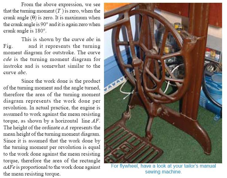
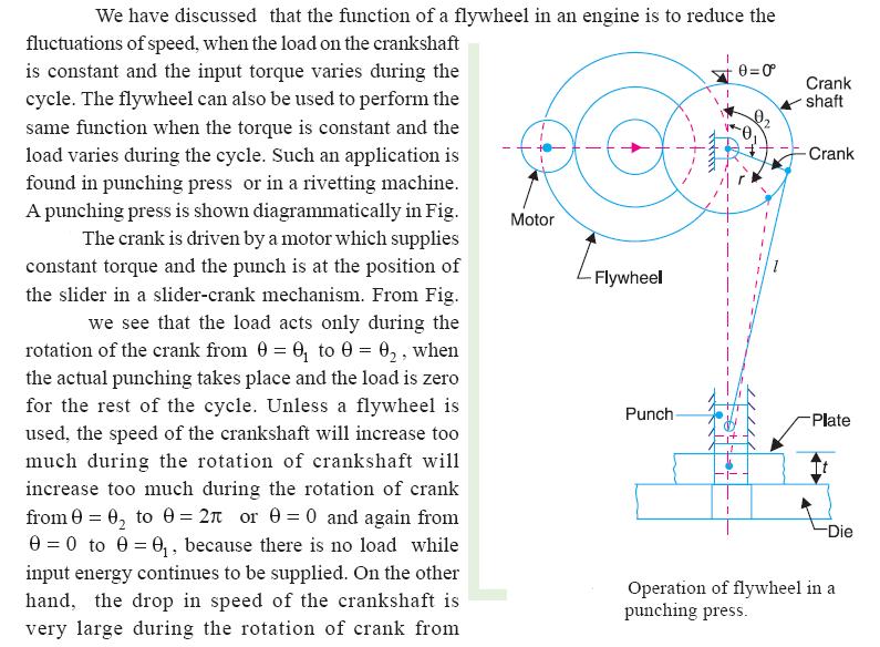
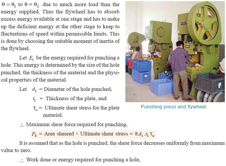
11 (16) Coefficient of fluctuation of speed: (17) Energy stored in flywheel: A flywheel is a rotating mass that is used as an energy reservoir in a machine. It absorbs energy in the form of kinetic energy, during those periods of crank rotation when actual turning moment is greater than the resisting moment and release energy, by way of parting with some of its K.E, when the actual turning moment is less than the resisting moment. (18) Flywheel in punching press: The flywheels used for prime movers constitute a class of problems in which the resisting torque is assumed to be constant and the driving torque varies. flywheels used in punching, riveting and similar machines constitute another class of problems in which the actual(driving) turning moment provided by an electric motor is more or less constant but the resisting torque(load) varies.
12
13

14 (19) Cam dynamics: Mechanism provides a non-linear I/O relationship. Different mechanism like single or multi-degree of freedom, intermittent motion mechanisms and linkages etc. have different I/O Relationship. When we can not obtain a certain functions from the well known mechanisms, we use a cam mechanism. It is a one degree of freedom mechanism of two moving links. One is cam and the other is follower. Rigid and elastic body cam system. Analysis of eccentric cam Problems on Cam follower system.
15 (20) Example Problems: 1) The variation of crankshaft torque of a four cylinder petrol engine may be approximately represented by taking the torque as zero for crank angles 0 and 180 and as 260 Nm for crank angles 20 and 45, the intermediate portions of the torque graph being straight lines. The cycle is being repeated in every half revolution. The average speed is 600 rpm. Supposing that the engine drives a machine requiring constant torque, determine the mass of the flywheel of radius of gyration 250 mm, which must be provided so that the total variation of speed shall be one percent. 2) A single cylinder vertical engine has a bore of 300 mm and a stroke of 400 mm. The connecting rod is 1 m long and the mass of the reciprocating parts is 140 kg. on the expansion stroke, with the crank at 30 from the top dead center, the gas pressure is 0.7 MPa. If the engine runs at 250 rpm, determine (i) net force acting on the piston (ii) resultant load on the gudgeon pin (iii) thrust on the cylinder walls, and (iv) the speed above which, other things remaining the same, the gudgeon pin load would be reversed in direction. 3) A vertical double acting steam engine has a cylinder 300 mm diameter and 450 mm stroke and runs at 200 rpm. The reciprocating parts has a mass of 225 kg and the piston rod is 50 mm diameter. The connecting rod is 1.2 m long. When the crank has turned through 125 from the top dead center the steam pressure above the piston is 30 kn/m 2 and below the piston is 1.5 kn/m 2. Calculate (i) Crank-pin effort and (ii) The effective turning moment on the crank shaft.
16 INDEX UNIT II BALANCING (1) Introduction (2) Balancing of rotating masses (3) Static balancing (4) Dynamic balancing (5) Various cases of balancing of rotating masses (6) Balancing of a single rotating mass by single mass rotating in the same plane (7) Balancing of a single rotating mass by two masses rotating in the different plane (8) Balancing of a several masses rotating in same plane (9) Balancing of several masses rotating different plane (10) Balancing of Reciprocating masses (11) Primary and secondary unbalanced forces of reciprocating parts (12) Balancing of single cylinder engine (13) Balancing of inertial forces in the multi-cylinder engine (14) Partial balancing of Locomotives (15) Variation of Tractive force (16) Swaying Couple (17) Hammer blow (18) Balancing of Inline engines (19) Balancing of radial engines (20) Example Problems
17 UNIT II BALANCING (1) Introduction: Balancing is the process of eliminating or at least reducing the ground forces and/or moments. It is achieved by changing the location of the mass centres of links. Balancing of rotating parts is a well known problem. A rotating body with fixed rotation axis can be fully balanced i.e. all the inertia forces and moments. For mechanism containing links rotating about axis which are not fixed, force balancing is possible, moment balancing by itself may be possible, but both not possible. We generally try to do force balancing. A fully force balance is possible, but any action in force balancing severe the moment balancing. (2) Balancing of rotating masses: The process of providing the second mass in order to counteract the effect of the centrifugal force of the first mass is called balancing of rotating masses. (3) Static balancing: The net dynamic force acting on the shaft is equal to zero. This requires that the line of action of three centrifugal forces must be the same. In other words, the centre of the masses of the system must lie on the axis of the rotation. This is the condition for static balancing. (4) Dynamic balancing: The net couple due to dynamic forces acting on the shaft is equal to zero. The algebraic sum of the moments about any point in the plane must be zero. (5) Various cases of balancing of rotating masses: Balancing of a single rotating mass by single mass rotating in the same plane. Balancing of a single rotating mass by two masses rotating in the different plane. Balancing of a several masses rotating in single plane. Balancing of a several masses rotating in different planes.
18 (6) Balancing of a single rotating mass by single mass rotating in the same plane:
19 (7) Balancing of a single rotating mass by two masses rotating in the different plane:
20
21
22 (8) Balancing of a several masses rotating in same plane:
23


24 (9) Balancing of several masses rotating different plane:
25

26 (10) Balancing of Reciprocating masses: Mass balancing encompasses a wide array of measures employed to obtain partial or complete compensation for the inertial forces and moments of inertia emanating from the crankshaft assembly. All masses are externally balanced when no free inertial forces or moments of inertia are transmitted through the block to the outside. However, the remaining internal forces and moments subject the engine mounts and block to various loads as well as deformities and vibratory stresses. The basic loads imposed by gas-based and inertial forces
27 (11) Primary and secondary unbalanced forces of reciprocating parts:
28 (12) Balancing of single cylinder engine: A single cylinder engine produces three main vibrations. In describing them we will assume that the cylinder is vertical. Firstly, in an engine with no balancing counterweights, there would be an enormous vibration produced by the change in momentum of the piston, gudgeon pin, connecting rod and crankshaft once every revolution. Nearly all single-cylinder crankshafts incorporate balancing weights to reduce this. While these weights can balance the crankshaft completely, they cannot completely balance the motion of the piston, for two reasons. The first reason is that the balancing weights have horizontal motion as well as vertical motion, so balancing the purely vertical motion of the piston by a crankshaft weight adds a horizontal vibration. The second reason is that, considering now the vertical motion only, the smaller piston end of the connecting rod (little end) is closer to the larger crankshaft end (big end) of the connecting rod in mid-stroke than it is at the top or bottom of the stroke, because of the connecting rod's angle. So during the 180 rotation from mid-stroke through top-dead-center and back to mid-stroke the minor contribution to the piston's up/down movement from the connecting rod's change of angle has the same direction as the major contribution to the piston's up/down movement from the up/down movement of the crank pin. By contrast, during the 180 rotation from mid-stroke through bottom-dead-center and back to mid-stroke the minor contribution to the piston's up/down movement from the connecting rod's change of angle has the opposite direction of the major contribution to the piston's up/down movement from the up/down movement of the crank pin. The piston therefore travels faster in the top half of the cylinder than it does in the bottom half, while the motion of the crankshaft weights is sinusoidal. The vertical motion of the piston is therefore not quite the same as that of the balancing weight, so they can't be made to cancel out completely. Secondly, there is a vibration produced by the change in speed and therefore kinetic energy of the piston. The crankshaft will tend to slow down as the piston speeds up and absorbs energy, and to speed up again as the piston gives up energy in slowing down at the top and bottom of the stroke. This vibration has twice the frequency of the first vibration, and absorbing it is one function of the flywheel. Thirdly, there is a vibration produced by the fact that the engine is only producing power during the power stroke. In a four-stroke engine this vibration will have half the frequency of the first vibration, as the cylinder fires once every two revolutions. In a two-stroke engine, it will have the same frequency as the first vibration. This vibration is also absorbed by the flywheel. (13) Balancing of inertial forces in the multi-cylinder engine: In multi-cylinder engines the mutual counteractions of the various components in the Crank shaft assembly are one of the essential factors determining the selection of the Crank shafts configuration and with it the design of the engine itself. The inertial forces are Balanced if the common centre of gravity for all moving crankshaft-assembly components lies at the crankshaft's midpoint, i.e. if the crankshaft is symmetrical (as viewed from the front). The crankshaft's symmetry level can be defined using geometrical representations of 1st- and 2ndorder forces (star diagrams). The 2nd order star diagram for the four-cylinder in-line engine is asymmetrical, meaning that this order is characterized by substantial free inertial Forces. These
29 forces can be balanced using two countershafts rotating in opposite directions at double the rate of the crankshaft (Lanchester system). (14) Partial balancing of Locomotives: (15) Variation of Tractive force: The resultant unbalanced force due to the cylinders, along the line of stroke, is known as tractive force.
30 (16) Swaying Couple: The couple has swaying effect about a vertical axis, and tends to sway the engine alternately in clock wise and anticlockwise directions. Hence the couple is known as swaying couple.
31 (17) Hammer blow: The maximum magnitude of the unbalanced force along the perpendicular to the line of stroke is known as Hammer blow.

32 (18) Balancing of Inline engines: An in-line engine is one wherein all the cylinders are arranged in a single line, one behind the other as schematically indicated in Fig. Many of the passenger cars found on Indian roads such as Maruti 800, Zen, Santro, Honda City, Honda CR-V, and Toyota Corolla all have four cylinder in-line engines. Thus this is a commonly employed engine and it is of interest to us to understand the analysis of its state of balance. For the sake of simplicity of analysis, we assume that all the cylinders are identical viz., r,, and are same. Further we assume that the rotating masses have been balanced out for all cylinders and we are left with only the forces due to the reciprocating masses. (19) Balancing of radial engines: A radial engine is one in which all the cylinders are arranged circumferentially as shown in Fig.These engines were quite popularly used in aircrafts during World War II. Subsequent developments in steam/gas turbines led to the near extinction of these engines. However it is still interesting to study their state of balance in view of some elegant results we shall discuss shortly. Our method of analysis remains identical to the previous case i.e., we proceed with the assumption that all cylinders are identical and the cylinders are spaced at uniform interval around the circumference.
33
34 (20) Example Problems: 1) A shaft carries four rotating masses A, B, C and D which are completely balanced. The masses B, C and D are 50 kg, 80 kg and 70 kg respectively. The masses C and D make angles of 90 and 195 respectively with mass B in the same sense. The masses A, B, C and D are concentrated at radius 75 mm, 100 mm, 50 mm and 80 mm respectively. The plane of rotation of masses B and C are 250 mm apart. Determine (i) the magnitude of mass A and its angular position and (ii) the position planes A and D. 2) The cranks of a two cylinder, uncoupled inside cylinder locomotive are at right angles and are 325 mm long. The cylinders are 675 mm apart. The rotating mass per cylinders are 200 kg at crank pin and the mass of the reciprocating parts per cylinder is 240 kg. The wheel center lines are 1.5 m apart. The whole of the rotating and two thirds of the reciprocating masses are to be balanced and the balance masses are to be placed in the planes of the rotation of the driving wheels at a radius of 800 mm. Find (i) the magnitude and direction of the balancing masses. (ii) the magnitude of hammer blow (iii) variation in tractive force and (iv) maximum swaying couple at a crank speed of 240 rpm. 3) (i) Four masses m 1, m 2, m 3 and m 4 attached to a rotating shaft on the same plane are 200 kg, 300 kg, 240 kg and 260 kg respectively. The corresponding radii of rotation are 0.2 m, 0.15 m, 0.25 m and 0.3 m respectively and the angles between successive masses are 45, 75 and 135. Find the position and magnitude of the balance mass required, if the radius of rotation is 0.2 m. (ii) Explain with neat sketches, balancing of single revolving mass, by masses in two different planes in a rotating system
35 INDEX UNIT III FREE VIBRATIONS (1) Introduction (2) Basic elements of vibration system (3) Causes of vibration (4) Effects of vibration (5) Methods of reduction of vibration (6) Types of vibratory motion (7) Terms used vibratory motion (8) Degrees of freedom (9) Single degree of freedom system (10) Two degree of freedom system (11) Types of Vibratory motion (12) Types of Vibration (13) Longitudinal Vibration (14) Free undamped longitudinal vibrations (15) Natural frequency of free undamped longitudinal vibration (16) Equivalent stiffness of spring (17) Damping (18) Types of damping (19) Damping Coefficient (20) Equivalent damping coefficient (21) Damped Vibration (22) Damping factor
36 (23) Logarithmic decrement (24) Transverse Vibration (25) Whirling of shaft (26) Torsional Vibration (27) Torsional vibration of a single rotor system (28) Torsional vibration of a two rotor system (29) Torsionally equivalent shaft (30) Example Problems
37 (1) Introduction: UNIT III FREE VIBRATIONS When a system is subjected to an initial disturbance and then left free to vibrate on its own, the resulting vibrations are referred to as free vibrations.free vibration occurs when a mechanical system is set off with an initial input and then allowed to vibrate freely. Examples of this type of vibration are pulling a child back on a swing and then letting go or hitting a tuning fork and letting it ring. The mechanical system will then vibrate at one or more of its "natural frequencies" and damp down to zero. (2) Basic elements of vibration system: Mass or Inertia Springiness or Restoring element Dissipative element (often called damper) External excitation (3) Causes of vibration: Unbalance: This is basically in reference to the rotating bodies. The uneven distribution of mass in a rotating body contributes to the unbalance. A good example of unbalance related vibration would be the vibrating alert in our mobile phones. Here a small amount of unbalanced weight is rotated by a motor causing the vibration which makes the mobile phone to vibrate. You would have experienced the same sort of vibration occurring in your front loaded washing machines that tend to vibrate during the spinning mode. Misalignment: This is an other major cause of vibration particularly in machines that are driven by motors or any other prime movers. Bent Shaft: A rotating shaft that is bent also produces the the vibrating effect since it losses it rotation capability about its center. Gears in the machine: The gears in the machine always tend to produce vibration, mainly due to their meshing. Though this may be controlled to some extent, any problem in the gearbox tends to get enhanced with ease. Bearings: Last but not the least, here is a major contributor for vibration. In majority of the cases every initial problem starts in the bearings and propagates to the rest of the members of the machine. A bearing devoid of lubrication tends to wear out fast and fails quickly, but before this is noticed it damages the remaining components in the machine and an initial look would seem as if something had gone wrong with the other components leading to the bearing failure.
38 (4) Effects of vibration: (a)bad Effects: The presence of vibration in any mechanical system produces unwanted noise, high stresses, poor reliability, wear and premature failure of parts. Vibrations are a great source of human discomfort in the form of physical and mental strains. (b)good Effects: A vibration does useful work in musical instruments, vibrating screens, shakers, relive pain in physiotherapy. (5) Methods of reduction of vibration: -unbalance is its main cause, so balancing of parts is necessary. -using shock absorbers. -using dynamic vibration absorbers. -providing the screens (if noise is to be reduced) (6) Types of vibratory motion: Free Vibration Forced Vibration (7) Terms used vibratory motion: (a)time period (or)period of vibration: It is the time taken by a vibrating body to repeat the motion itself.time period is usually expressed in seconds. (b) Cycle: It is the motion completed in one time period. (c) Periodic motion: A motion which repeats itself after equal interval of time. (d)amplitude (X) The maximum displacement of a vibrating body from the mean position.it is usually expressed in millimeter. (e) Frequency (f) The number of cycles completed in one second is called frequency
 Single degree of freedom system: The system shown in this figure is what is known as a Single Degree of Freedom system.")

39 (8) Degrees of freedom: The minimum number of independent coordinates required to specify the motion of a system at any instant is known as D.O.F of the system. (9) Single degree of freedom system: The system shown in this figure is what is known as a Single Degree of Freedom system. We use the term degree of freedom to refer to the number of coordinates that are required to specify completely the configuration of the system. Here, if the position of the mass of the system is specified then accordingly the position of the spring and damper are also identified. Thus we need just one coordinate (that of the mass) to specify the system completely and hence it is known as a single degree of freedom system. (10) Two degree of freedom system:

40 A two degree of freedom system With reference to automobile applications, this is referred as quarter car model. The bottom mass refers to mass of axle, wheel etc components which are below the suspension spring and the top mass refers to the mass of the portion of the car and passenger. Since we need to specify both the top and bottom mass positions to completely specify the system, this becomes a two degree of freedom system. (11) Types of Vibratory motion: (12) Types of Vibration: (a)longitudinal vibration (b)transverse Vibration ( c)torsional Vibration.
41 (13) Longitudinal Vibration: When the particles of the shaft or disc moves parallel to the axis of the shaft, then the vibrations known as longitudinal vibrations. (14) Free undamped longitudinal vibrations; When a body is allowed to vibrate on its own, after giving it an initial displacement, then the ensuring vibrations are known as free or natural vibrations. When the vibrations take place parallel to the axis of constraint and no damping is provided, then it is called free undamped longitudinal vibrations. (15) Natural frequency of free undamped longitudinal vibration: (15.a) Equilibrium method or Newton s method:
42
43
is constant and is same all the times.")
44 (15.b)Energy Method In free vibrations, no energy is transferred into the system or from the system. Therefore, the total energy (sum of KE and PE)is constant and is same all the times.
 Equivalent stiffness of spring.")
45 (c)rayleigh s method In this method, the maximum kinetic energy at mean position is made equal to the maximum potential energy at the extreme position. (16) Equivalent stiffness of spring. (1) Springs in series (2) Springs in parallel (3) Combined springs (4) Inclined springs
 Types of damping: (1) Viscous damping (2) Dry friction or coulomb damping (3) Solid damping or structural damping (4) Slip or interfacial")
46 (17) Damping: It is the resistance to the motion of a vibrating body. The vibrations associated with this resistance are known as damped vibrations. (18) Types of damping: (1) Viscous damping (2) Dry friction or coulomb damping (3) Solid damping or structural damping (4) Slip or interfacial damping.
47 (19) Damping Coefficient: The damping force per unit velocity is known as damping coefficient. (20) Equivalent damping coefficient: Dampers may be connected either in series or in parallel to provide required damping. (21) Damped Vibration: The vibrations associated with this resistance are known as damped vibrations. (22) Damping factor: Damping factor can be defined as the ratio of actual damping coefficient to critical damping coefficient.

48 Thus mainly three cases arise depending on the value of When the system undergoes aperiodically decaying motion and hence such systems are said to be Overdamped Systems. An example of such a system is a door damper when we open a door and enter a room, we want the door to gradually close rather than exhibit oscillatory motion and bang into the person entering the room behind us! So the damper is designed such that Critically damped motion ( a hypothetical borderline case separating oscillatory decay from a periodic decay) I the fastest decaying aperiodic motion. When < 1, x(t) is a damped sinusoid and the system exhibits a vibratory motion whose amplitude keeps diminishing. This is the most common vibration case and we will spend most of our time studying such systems. These are referred to as Underdamped systems. (23) Logarithmic decrement: It is defined as the natural logarithm of ratio of any two successive amplitudes of an under damped system. It is a dimensionless quantity. We define Damping factor as
49 (24) Transverse Vibration: When the particles of the shaft or disc moves approximately perpendicular to the axis of the shaft, then the vibrations known as transverse vibrations.
50 (25) Whirling speed of shaft: The speed, at which the shaft runs so that the additional deflection of the shaft from the axis of rotation becomes infinite, is known as critical or whirling speed. No shaft can ever be perfectly straight or perfectly balanced. When an element of mass is a distance from the axis of rotation, centrifugal force, will tend to pull the mass outward. The elastic properties of the shaft will act to restore the straightness. If the frequency of rotation is equal to one of the resonant frequencies of the shaft, whirling will occur. In order to save the machine from failure, operation at such whirling speeds must be avoided. The whirling frequency of a symmetric cross section of a given length between two points is given by: RPM Where E = young's modulus, I = Second moment of area, m = mass of the shaft, L= length of the shaft between points A shaft with weights added will have an angular velocity of N (rpm) equivalent as follows:
51 (26) Torsional Vibration: When the particles of the shaft or disc move in a circle about the axis of the shaft, then the vibrations known as tensional vibration
52
53 (27) Torsional vibration of a single rotor system:
54 (28) Torsional vibration of a two rotor system:
55 (29) Torsionally equivalent shaft:
56 (30) Example Problems: 1) A spring mass system has spring stiffness of k N/m and a mass of M kg. It has the natural frequency of vibration as 12 Hz. An extra 2 kg mass is coupled to M and the natural frequency reduces by 2 Hz. Find the values of k and M. 2) A stepped shaft of 0.05 m in diameter for the first 0.6 m length, 0.08 m diameter for the next 1.8 m and 0.03 m diameter for the remaining 0.25 m length. While the 0.05 m diameter end is fixed, the 0.03 m diameter end of the shaft carries a rotor of mass moment of inertia 14.7 kg-m 2. If the modulus of elasticity of the shaft material is 0.83 x N/m 2, find the natural frequency of torsional oscillations, neglecting the inertia effect of the shaft. 3). Between a solid mass of 10 kg and the floor are kept two slabs of isolators, natural rubber and felt, in series. The natural rubber slab has a stiffness of 3000 N/m and an equivalent viscous damping coefficient of 100 N.sec/m. The felt slab has a stiffness of N/m and equivalent viscous damping coefficient of 330 N.sec/m. Determine the undamped and the damped natural frequencies of the system in vertical direction, neglecting the mass of isolators.
57 INDEX UNIT IV FORCED VIBRATIONS (1)Introduction (2) Causes resonance (3) Forced vibration of a single degree-of-freedom system (4) Steady State Response due to Harmonic Oscillation (5) Forced vibration with damping (6) Rotating unbalance forced vibration (7) Vibration Isolation and Transmissibility (8) Vibration Isolators (9) Response without damping (10) Example Problems
58 UNIT- IV FORCED VIBRATION (1) Introduction: When a system is subjected continuously to time varying disturbances, the vibrations resulting under the presence of the external disturbance are referred to as forced vibrations. Forced vibration is when an alternating force or motion is applied to a mechanical system. Examples of this type of vibration include a shaking washing machine due to an imbalance, transportation vibration (caused by truck engine, springs, road, etc), or the vibration of a building during an earthquake. In forced vibration the frequency of the vibration is the frequency of the force or motion applied, with order of magnitude being dependent on the actual mechanical system. When a vehicle moves on a rough road, it is continuously subjected to road undulations causing the system to vibrate (pitch, bounce, roll etc). Thus the automobile is said to undergo forced vibrations. Similarly whenever the engine is turned on, there is a resultant residual unbalance force that is transmitted to the chassis of the vehicle through the engine mounts, causing again forced vibrations of the vehicle on its chassis. A building when subjected to time varying ground motion (earthquake) or wind loads, undergoes forced vibrations. Thus most of the practical examples of vibrations are indeed forced vibrations. (2) Causes resonance: Resonance is simple to understand if you view the spring and mass as energy storage elements with the mass storing kinetic energy and the spring storing potential energy. As discussed earlier, when the mass and spring have no force acting on them they transfer energy back and forth at a rate equal to the natural frequency. In other words, if energy is to be efficiently pumped into both the mass and spring the energy source needs to feed the energy in at a rate equal to the natural frequency. Applying a force to the mass and spring is similar to pushing a child on swing, you need to push at the correct moment if you want the swing to get higher and higher. As in the case of the swing, the force applied does not necessarily have to be high to get large motions; the pushes just need to keep adding energy into the system. The damper, instead of storing energy, dissipates energy. Since the damping force is proportional to the velocity, the more the motion, the more the damper dissipates the energy. Therefore a point will come when the energy dissipated by the damper will equal the energy being fed in by the force. At this point, the system has reached its maximum amplitude and will continue to vibrate at this level as long as the force applied stays the same. If no damping exists, there is nothing to dissipate the energy and therefore theoretically the motion will continue to grow on into infinity.
59 (3) Forced vibration of a single degree-of-freedom system: We saw that when a system is given an initial input of energy, either in the form of an initial displacement or an initial velocity, and then released it will, under the right conditions, vibrate freely. If there is damping in the system, then the oscillations die away. If a system is given a continuous input of energy in the form of a continuously applied force or a continuously applied displacement, then the consequent vibration is called forced vibration. The energy input can overcome that dissipated by damping mechanisms and the oscillations are sustained. We will consider two types of forced vibration. The first is where the ground to which the system is attached is itself undergoing a periodic displacement, such as the vibration of a building in an earthquake. The second is where a periodic force is applied to the mass, or object performing the motion; an example might be the forces exerted on the body of a car by the forces produced in the engine. The simplest form of periodic force or displacement is sinusoidal, so we will begin by considering forced vibration due to sinusoidal motion of the ground. In all real systems, energy will be dissipated, i.e. the system will be damped, but often the damping is very small. So let us first analyze systems in which there is no damping. (4) Steady State Response due to Harmonic Oscillation: Consider a spring-mass-damper system as shown in figure 4.1. The equation of motion of this system subjected to a harmonic force can be given by where, m, k and c are the mass, spring stiffness and damping coefficient of the system, F is the amplitude of the force, w is the excitation frequency or driving frequency. (4.1) Figure 4.1 Harmonically excited system
60 Figure 4.2: Force polygon The steady state response of the system can be determined by solving equation(4.1) in many different ways. Here a simpler graphical method is used which will give physical understanding to this dynamic problem. From solution of differential equations it is known that the steady state solution (particular integral) will be of the form As each term of equation (4.1) represents a forcing term viz., first, second and third terms, represent the inertia force, spring force, and the damping forces. The term in the right hand side of equation (4.1) is the applied force. One may draw a close polygon as shown in figure 4.2 considering the equilibrium of the system under the action of these forces. Considering a reference line these forces can be presented as follows. (4.2) Spring force = (This force will make an angle with the reference line, represented by line OA). Damping force = (This force will be perpendicular to the spring force, represented by line AB). Inertia force = (this force is perpendicular to the damping force and is in opposite direction with the spring force and is represented by line BC). Applied force = which can be drawn at an angle with respect to the reference line and is represented by line OC. From equation (1), the resultant of the spring force, damping force and the inertia force will be the applied force, which is clearly shown in figure 4.2. It may be noted that till now, we don't know about the magnitude of X and which can be easily computed from Figure 2. Drawing a line CD parallel to AB, from the triangle OCD of Figure 2,
61 From the previous module of free-vibration it may be recalled that Natural frequency Critical damping Damping factor or damping ratio Hence, or As the ratio is the static deflection of the spring, is known as the magnification factor or amplitude ratio of the system
62 (5) Forced vibration with damping: In this section we will see the behaviour of the spring mass damper model when we add a harmonic force in the form below. A force of this type could, for example, be generated by a rotating imbalance. If we again sum the forces on the mass we get the following ordinary differential equation: The steady state solution of this problem can be written as: The result states that the mass will oscillate at the same frequency, f, of the applied force, but with a phase shift φ. The amplitude of the vibration X is defined by the following formula. Where r is defined as the ratio of the harmonic force frequency over the undamped natural frequency of the mass spring damper model. The phase shift, φ, is defined by the following formula. The plot of these functions, called "the frequency response of the system", presents one of the most important features in forced vibration. In a lightly damped system when the forcing frequency nears the natural frequency ( ) the amplitude of the vibration can get extremely
63 high. This phenomenon is called resonance (subsequently the natural frequency of a system is often referred to as the resonant frequency). In rotor bearing systems any rotational speed that excites a resonant frequency is referred to as a critical speed. If resonance occurs in a mechanical system it can be very harmful leading to eventual failure of the system. Consequently, one of the major reasons for vibration analysis is to predict when this type of resonance may occur and then to determine what steps to take to prevent it from occurring. As the amplitude plot shows, adding damping can significantly reduce the magnitude of the vibration. Also, the magnitude can be reduced if the natural frequency can be shifted away from the forcing frequency by changing the stiffness or mass of the system. If the system cannot be changed, perhaps the forcing frequency can be shifted (for example, changing the speed of the machine generating the force). The following are some other points in regards to the forced vibration shown in the frequency response plots. At a given frequency ratio, the amplitude of the vibration, X, is directly proportional to the amplitude of the force F 0 (e.g. if you double the force, the vibration doubles) With little or no damping, the vibration is in phase with the forcing frequency when the frequency ratio r < 1 and 180 degrees out of phase when the frequency ratio r > 1 When r 1 the amplitude is just the deflection of the spring under the static force F 0. This deflection is called the static deflection δ st. Hence, when r 1 the effects of the damper and the mass are minimal. When r 1 the amplitude of the vibration is actually less than the static deflection δ st. In this region the force generated by the mass (F = ma) is dominating because the acceleration seen by the mass increases with the frequency. Since the deflection seen in the spring, X, is reduced in this region, the force transmitted by the spring (F = kx) to the base is reduced. Therefore the mass spring damper system is isolating the harmonic force from the mounting base referred to as vibration isolation. Interestingly, more damping actually reduces the effects of vibration isolation when r 1 because the damping force (F = cv) is also transmitted to the base.
64 (6) Rotating unbalance forced vibration: One may find many rotating systems in industrial applications. The unbalanced force in such a system can be represented by a mass m with eccentricity e, which is rotating with angular velocity as shown in Figure 4.1. Figure 4.1 : Vibrating system with rotating unbalance Figure 4.2. Freebody diagram of the system Let x be the displacement of the nonrotating mass (M-m) from the static equilibrium position, then the displacement of the rotating mass m is From the freebody diagram of the system shown in figure 4.2, the equation of motion is
65 (4.1) or (4.2) This equation is same as equation (1) where F is replaced by as shown in figure 4.3. So from the force polygon (4.3) or (4.4) or (4.5) Figure 4.3: Force polygon or (4.6)
66 and (4.7) So the complete solution becomes (4.8) (7) Vibration Isolation and Transmissibility: When a machine is operating, it is subjected to several time varying forces because of which it tends to exhibit vibrations. In the process, some of these forces are transmitted to the foundation which could undermine the life of the foundation and also affect the operation of any other machine on the same foundation. Hence it is of interest to minimize this force transmission. Similarly when a system is subjected to ground motion, part of the ground motion is transmitted to the system as we just discussed e.g., an automobile going on an uneven road; an instrument mounted on the vibrating surface of an aircraft etc. In these cases, we wish to minimize the motion transmitted from the ground to the system. Such considerations are used in the design of machine foundations and in order to understand some of the basic issues involved, we will study this problem based on the single d.o.f model discussed so far. we get the expression for force transmitted to the base as follows: (8) Vibration Isolators: Consider a vibrating machine; bolted to a rigid floor (Figure 2a).The force transmitted to the floor is equal to the force generated in the machine. The transmitted force can be decreased by adding a suspension and damping elements (often called vibration isolators) Figure 2b, or by adding what is called an inertia block, a large mass (usually a block of cast concrete), directly attached to the machine (Figure 2c).Another option is to add an additional level of mass (sometimes called a seismic mass, again a block of cast concrete) and suspension (Figure 2d).
 Supported on isolation springs, non-rigid foundation (such as a floor); or machine on isolation springs, seismic mass and second level of isolator springs When oscillatory forces arise unavoidably")
67 Figure 2.Vibration isolation systems: a) Machine bolted to a rigid foundation b) Supported on isolation springs, rigid foundation c) machine attached to an inertial block. d) Supported on isolation springs, non-rigid foundation (such as a floor); or machine on isolation springs, seismic mass and second level of isolator springs When oscillatory forces arise unavoidably in machines it is usually desired to prevent these forces from being transmitted to the surroundings. For example, some unbalanced forces are inevitable in a car engine, and it is uncomfortable if these are wholly transmitted to the car body. The usual solution is to mount the source of vibration on sprung supports. Vibration isolation is measured in terms of the motion or force transmitted to the foundation. The lesser the force or motion transmitted the greater the vibration isolation Suppose that the foundation is effectively rigid and that only one direction of movement is effectively excited so that the system can be treated as having only one degree of freedom. (9) Response without damping: The amplitude of the force transmitted to the foundations is Where k is the Stiffness of the support and x(t) is the displacement of the mass m. The governing equation can be determined by considering that the total forcing on the machine is equal to its mass multiplied by its acceleration (Newton s second law)
68 (10) Example Problems: 1) A mass of 10 kg is suspended from one end of a helical spring, the other end being fixed. The stiffness of the spring is 10 N/mm. The viscous damping causes the amplitude to decrease to one tenth of the initial value in four complete oscillations. If a periodic force of 150 cos 50 t N is applied at the mass in the vertical direction, find the amplitude of the forced vibrations. What is its value at resonance? 2) A machine supported symmetrically on four springs has a mass of 80 kg. The mass of the reciprocating parts is 2.2 kg which move through a vertical stroke of 100 mm with simple harmonic motion. Neglecting damping, determine the combined stiffness of the spring so that the force transmitted to foundation is 1/20 th of the impresses force. The machine crank shaft rotates at 800 rpm. If under working conditions, the damping reduces the amplitudes of successive vibrations by 30%, find (i) the force transmitted to the foundation at resonance and (ii) the amplitude of vibration at resonance.
69 INDEX UNIT- V MECHANISM FOR CONTROL (1) Introduction (2) Principle of Working (3) Classification of governors (4) Height of governor (5) Sleeve lift (6) Isochronism (7) Stability (8) Hunting (9) Sensitiveness (10) Characteristics and qualities of centrifugal governor (11)Watt governor (12)Porter governor (13)Proell governor (14) Hartnell governor (15) Hartung governor (16) Wilson Hartnell governor (17)Pickering governor (18) Difference between a flywheel and a governor (19) Gyroscope (20) Description and diagram ( 2 1 ) E f f e c t o f t h e G y r o s c o p i c C o u p l e o n a n A e r o p l a n e (22) Effect of gyroscopic couple (23) Effect of gyroscopic couple on ship (24) Effect of Gyroscopic Couple on a Naval Ship during pitching
70 (25) Effect of Gyroscopic couple on a Naval Ship during Rolling (26) Effect of Gyroscopic couple on a 4 -wheel drive (27) Example Problems
71 (1)Introduction: UNIT- V MECHANISM FOR CONTROL Governor A centrifugal governor is a specific type of governor that controls the speed of an engine by regulating the amount of fuel (or working fluid) admitted, so as to maintain a near constant speed whatever the load or fuel supply conditions. It uses the principle of proportional control. It is most obviously seen on steam engines where it regulates the admission of steam into the cylinder(s). It is also found on internal combustion engines and variously fuelled turbines, and in some modern striking clocks. (2)Principle of Working: Power is supplied to the governor from the engine's output shaft by (in this instance) a belt or chain (not shown) connected to the lower belt wheel. The governor is connected to a throttle valve that regulates the flow of working fluid (steam) supplying the prime mover (prime mover not shown). As the speed of the prime mover increases, the central spindle of the governor rotates at a faster rate and the kinetic energy of the balls increases. This allows the two masses on lever arms to move outwards and upwards against gravity. If the motion goes far enough, this motion causes the lever arms to pull down on a thrust bearing, which moves a beam linkage, which reduces the aperture of a throttle valve. The rate of working-fluid entering
72 the cylinder is thus reduced and the speed of the prime mover is controlled, preventing over speeding. Mechanical stops may be used to limit the range of throttle motion, as seen near the masses in the image at right. The direction of the lever arm holding the mass will be along the vector sum of the reactive centrifugal force vector and the gravitational force. (3) Classification of governors: Governors are classified based upon two different principles. These are: 1. Centrifugal governors 2. Inertia governors Centrifugal governors are further classified as (4) Height of governor It is the vertical distance between the centre of the governor halls and the point of intersection between the upper arms on the axis of spindle is known as governor height. It is generally denoted by h.
73 (5) Sleeve lift The vertical distance the sleeve travels due to change in the equilibrium Speed is called the sleeve lift. The vertical downward travel may be termed as Negative lift (6) Isochronism This is an extreme case of sensitiveness. When the equilibrium speed is constant for all radii of rotation of the balls within the working range, the governor is said to be in isochronism. This means that the difference between the maximum and minimum equilibrium speeds is zero and the sensitiveness shall be infinite. (7) Stability Stability is the ability to maintain a desired engine speed without Fluctuating. Instability results in hunting or oscillating due to over correction. Excessive stability results in a dead-beat governor or one that does not correct sufficiently for load changes (8) Hunting The phenomenon of continuous fluctuation of the engine speed above and below the mean speed is termed as hunting. This occurs in over- sensitive or isochronous governors. Suppose an isochronous governor is fitted to an engine running at a steady load. With a slight increase of load, the speed will fall and the sleeve will immediately fall to its lowest position. This shall open the control valve wide and excess supply of energy will be given, with the result that the speed will rapidly increase and the sleeve will rise to its higher position. As a result of this movement of the sleeve, the control valve will be cut off; the supply to the engine and the speed will again fall, the cycle being repeated indefinitely. Such a governor would admit either more or less amount of fuel and so effect would be that the engine would hunt. (9) Sensitiveness A governor is said to be sensitive, if its change of speed s from no Load to full load may be as small a fraction of the mean equilibrium speed as possible and the corresponding sleeve lift may be as large as possible. Suppose ω1 = max. Equilibrium speed ω2 = min. equilibrium speed ω = mean equilibrium speed = (ω1+ ω2)/2 Therefore sensitiveness = (ω1- ω2)/2
74 (10) Characteristics and qualities of centrifugal governor: For satisfactory performance and working a centrifugal governor should possess The following qualities. a. On the sudden removal of load its sleeve should reach at the top most position at Once. b. Its response to the change of speed should be fast. c. Its sleeve should float at some intermediate position under normal operating Conditions. d. At the lowest position of sleeve the engine should develop maximum power. e. It should have sufficient power, so that it may be able to exert the required force At the sleeve to operate the control & mechanism (11)Watt governor:
75
76 (12) Porter governor:
77 (13)Proell governor: (14) Hartnell governor:
78 (15) Hartung governor:
79 (16) Wilson Hartnell governor:
80 (17)Pickering governor: (18) Difference between a flywheel and a governor:

81 Gyroscope and its applications (19) Gyroscope A gyroscope is a device for measuring or maintaining orientation, based on the principles of conservation of angular momentum. A mechanical gyroscope is essentially a spinning wheel or disk whose axle is free to take any orientation. This orientation changes much less in response to a given external torque than it would without the large angular momentum associated with the gyroscope's high rate of spin. Since external torque is minimized by mounting the device in gimbals, its orientation remains nearly fixed, regardless of any motion of the platform on which it is mounted. Gyroscopes based on other operating principles also Exit, such as the electronic, microchip-packaged MEMS gyroscope devices found in consumer electronic devices, solid state ring lasers, fiber optic gyroscopes and the extremely sensitive quantum gyroscope. Applications of gyroscopes include navigation (INS) when magnetic compasses do not work (as in the Hubble telescope) or are not precise enough (as in ICBMs) or for the stabilization of flying vehicles like radio-controlled helicopters or UAVs. Due to higher precision, gyroscopes are also used to maintain direction in tunnel mining.
82 (20) Description and diagram: Diagram of a gyro wheel. Reaction arrows about the output axis (blue) correspond to forces applied about the input axis (green), and vice versa. Within mechanical systems or devices, a conventional gyroscope is a mechanism comprising a rotor journal led to spin about one axis, the journals of the rotor being mounted in an inner gimbal or ring, the inner gimbal is journal led for oscillation in an outer gimbal which is journal led in another gimbal. So basically there are three gimbals. The outer gimbal or ring which is the gyroscope frame is mounted so as to pivot about an axis in its own plane determined by the support. This outer gimbal possesses one degree of rotational freedom and its axis possesses none. The next inner gimbal is mounted in the gyroscope frame (outer gimbal) so as to pivot about an axis in its own plane that is always perpendicular to the pivotal axis of the gyroscope frame (outer gimbal). This inner gimbal has two degrees of rotational freedom. Similarly, next innermost gimbal is attached to the inner gimbal which has three degree of rotational freedom and its axis posses two. The axle of the spinning wheel defines the spin axis. The rotor is journaled to spin about an axis which is always perpendicular to the axis of the innermost gimbal. So, the rotor possesses four degrees of rotational freedom and its axis possesses three. The wheel responds to a force applied about the input axis by a reaction force about the output axis. The behavior of a gyroscope can be most easily appreciated by consideration of the front wheel of a bicycle. If the wheel is leaned away from the vertical so that the top of the wheel moves to the left, the forward rim of the wheel also turns to the left. In other words, rotation on one axis of the turning wheel produces rotation of the third axis.
83 ( 21) E f f e c t of t h e G y r o s c o p i c C o u p l e o n a n A e r o p l a ne (22) EFFECT OF GYROSCOPIC COUPLE This couple is, therefore, to raise the nose and dip the tail of the aero plane. Notes 1. When the aero plane takes a right turn under similar Conditions as discussed above, the effect of the reactive Couple will be to dip the nose and raise the tail of the aero plane. 2. When the engine or propeller rotates in anticlockwise direction when viewed from the rear or tail end and the aero plane takes a left turn, then the effect of reactive gyroscopic couple will be to dip the nose and raise the tail of the aero plane. 3. When the aero plane takes a right turn under similar Conditions as mentioned in note 2 above, the effect of Reactive gyroscopic couple will be to raise the nose and dip the of the aero plane. 4. When the engine or propeller rotates in clockwise direction when viewed from the front and the aero plane takes a left turn, then the effect of reactive gyroscopic couple will be to raise the tail and dip the nose of the aero plane. 5. When the aero plane takes a right turn under similar conditions as mentioned in note4 above, the effect of reactive gyroscopic couple will be to raise the nose and dip the tail of the aero plane. (23) Effect of gyroscopic couple on ship The top and front views of a naval ship are shown in fig. The fore end of the ship is called bow and the rear end is known as stern or aft. The left hand and the right hand sides of the ship, when viewed from the stern are called port and star board respectively. We shall now discuss the effect of gyroscopic couple in the naval ship in the following three cases: 1. Steering 2. Pitching, and 3. Rolling
84 (24) Effect of Gyroscopic Couple on a Naval Ship during pitching& Steering Steering is the turning of a complete ship in a curve towards left or right, while it moves forward, considers the ship taking a left turn, and rotor rotates in the clockwise direction when viewed from the stern, as shown in Fig. below. The effect of gyroscopic couple on a naval ship during steering taking left or right turn may be obtained in the similar way as for an aero plane as discussed in Art. When the rotor of the ship rotates in the clockwise direction when viewed from the stern, it will have its angular momentum vector in the direction ox as shown in Fig. A1. As the ship steers to the left, the active gyroscopic couple will change the angular momentum vector from ox to ox. The vector xx now represents the active gyroscopic couple and is perpendicular to ox. Thus the plane of active gyroscopic couple is
85 perpendicular to xx and its direction in the axis OZ for left hand turn is clockwise as shown in Fig below. The reactive gyroscopic couple of the same magnitude will act in the opposite direction (i.e in anticlockwise direction). The effect of this reactive gyroscopic couple is to raise the bow and lower the stern. Notes 1. When the ship steers to the right under similar condition as discussed above, the effect of the reactive gyroscopic couple, as shown in Fig. B1, will be to raise the stern and lower the bow. 2. When the rotor rotates in the anticlockwise direction, when viewed from the stern and the ship is steering to the left, then the effect of reactive gyroscopic couple will be to lower the bow and raise the stern. 3. When the ship is steering to the right under similar conditions as discussed in note 2 above, then the effect of reactive gyroscopic couple will be to raise the bow and lower the stern. 4. When the rotor rotates in the clockwise direction when viewed from the bow or fore end and the ship is steering to the left, then the effect of reactive gyroscopic couple will be to raise the stern and lower the bow. 5. When the ship is steering to the right under similar conditions as discussed in note 4 above, then the effect of reactive gyroscopic couple will be to raise the bow and lower the stern. 6. The effect of the reactive gyroscopic couple on a boat propelled by a turbine taking left or right turn. (25) Effect of Gyroscopic couple on a Naval Ship during Rolling: We know that, for the effect of gyroscopic couple to occur, the axis of precession should always be perpendicular to the axis of spin. If, however, the axis of precession becomes parallel to the axis of spin, there will be no effect of the gyroscopic couple acting on the body of the ship. In case of rolling of a ship, the axis of precession (i.e. longitudinal axis) is always parallel to the axis of spin for all positions. Hence, there is no effect of the gyroscopic couple acting on the body of a ship.
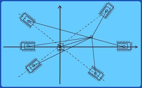
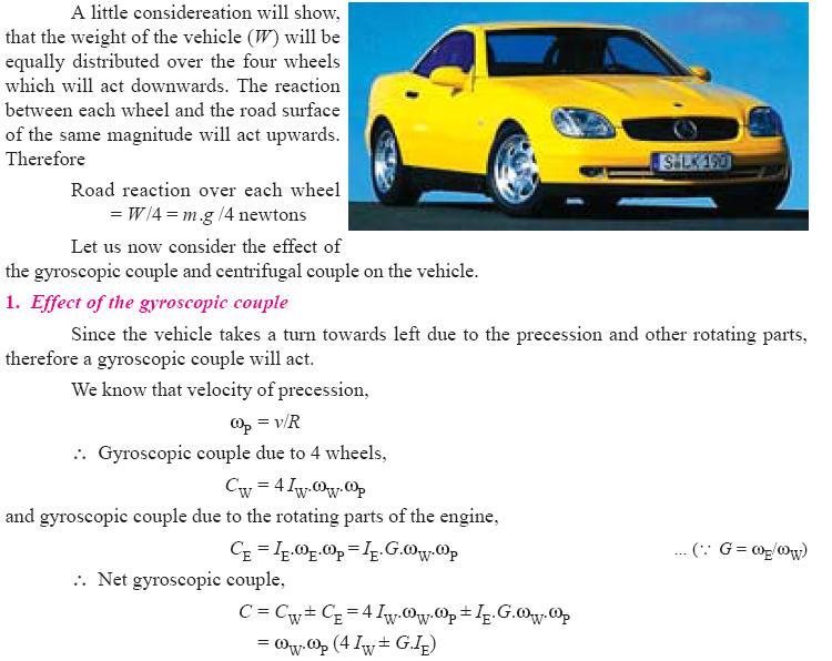
86 (26) Effect of Gyroscopic couple on a 4-wheel drive:
87
R10 Set No: 1 ''' ' '' '' '' Code No: R31033
 R10 Set No: 1 III B.Tech. I Semester Regular and Supplementary Examinations, December - 2013 DYNAMICS OF MACHINERY (Common to Mechanical Engineering and Automobile Engineering) Time: 3 Hours Max Marks:
B.TECH III Year I Semester (R09) Regular & Supplementary Examinations November 2012 DYNAMICS OF MACHINERY
 Regular & Supplementary Examinations November 2012 DYNAMICS OF MACHINERY") 1 B.TECH III Year I Semester (R09) Regular & Supplementary Examinations November 2012 DYNAMICS OF MACHINERY (Mechanical Engineering) Time: 3 hours Max. Marks: 70 Answer any FIVE questions All questions
1 B.TECH III Year I Semester (R09) Regular & Supplementary Examinations November 2012 DYNAMICS OF MACHINERY (Mechanical Engineering) Time: 3 hours Max. Marks: 70 Answer any FIVE questions All questions
III B.Tech I Semester Supplementary Examinations, May/June
 Set No. 1 III B.Tech I Semester Supplementary Examinations, May/June - 2015 1 a) Derive the expression for Gyroscopic Couple? b) A disc with radius of gyration of 60mm and a mass of 4kg is mounted centrally
2. Write the expression for estimation of the natural frequency of free torsional vibration of a shaft. (N/D 15)
") ME 6505 DYNAMICS OF MACHINES Fifth Semester Mechanical Engineering (Regulations 2013) Unit III PART A 1. Write the mathematical expression for a free vibration system with viscous damping. (N/D 15) Viscous
ME 6505 DYNAMICS OF MACHINES Fifth Semester Mechanical Engineering (Regulations 2013) Unit III PART A 1. Write the mathematical expression for a free vibration system with viscous damping. (N/D 15) Viscous
CHAPTER 1 BALANCING BALANCING OF ROTATING MASSES
 CHAPTER 1 BALANCING Dynamics of Machinery ( 2161901) 1. Attempt the following questions. I. Need of balancing II. Primary unbalanced force in reciprocating engine. III. Explain clearly the terms static
Chapter 15. Inertia Forces in Reciprocating Parts
 Chapter 15 Inertia Forces in Reciprocating Parts 2 Approximate Analytical Method for Velocity and Acceleration of the Piston n = Ratio of length of ConRod to radius of crank = l/r 3 Approximate Analytical
Chapter 15. Inertia Forces in Reciprocating Parts
 Chapter 15 Inertia Forces in Reciprocating Parts 2 Approximate Analytical Method for Velocity & Acceleration of the Piston n = Ratio of length of ConRod to radius of crank = l/r 3 Approximate Analytical
INDEX UNIT- IV MECHANISM FOR CONTROL (1) Introduction (2) Principle of Working (3) Classification of governors (4) Height of governor (5) Sleeve lift
 Introduction (2) Principle of Working (3) Classification of governors (4) Height of governor (5) Sleeve lift") INDEX UNIT- IV MECHANISM FOR CONTROL (1) Introduction (2) Principle of Working (3) Classification of governors (4) Height of governor (5) Sleeve lift (6) Isochronism s (7) Stability (8) Hunting (9) Sensitiveness
INDEX UNIT- IV MECHANISM FOR CONTROL (1) Introduction (2) Principle of Working (3) Classification of governors (4) Height of governor (5) Sleeve lift (6) Isochronism s (7) Stability (8) Hunting (9) Sensitiveness
Theory of Machines. CH-1: Fundamentals and type of Mechanisms
 CH-1: Fundamentals and type of Mechanisms 1. Define kinematic link and kinematic chain. 2. Enlist the types of constrained motion. Draw a label sketch of any one. 3. Define (1) Mechanism (2) Inversion
Fatima Michael College of Engineering & Technology
 DEPARTMENT OF MECHANICAL ENGINEERING STAFF NAME: Mr.M. BEJU MOHAN M.E., SUBJECT: ME6505-DYNAMICS OF MACHINES QUESTION BANK YEAR/SEM: III/V UNIT-I (FORCE ANALYSIS) PART-A (2 marks) 1. State the principle
SYLLABUS. osmania university. Force Analysis of Four-Bar and Slider Crank Mechanisms. CHAPTER - 2 : DYNAMIC FORCE ANALYSIS
 Contents i SYLLABUS osmania university UNIT - I CHAPTER - 1 : STATIC TIC FORCE ANALYSIS Force Analysis of Four-Bar and Slider Crank Mechanisms. CHAPTER - 2 : DYNAMIC FORCE ANALYSIS Force Analysis of Four-Bar
INSTITUTE OF AERONAUTICAL ENGINEERING (Autonomous) Dundigal, Hyderabad
 Dundigal, Hyderabad") INSTITUTE OF AERONAUTICAL ENGINEERING (Autonomous) Dundigal, Hyderabad -500 043 MECHANICAL ENGINEERING TUTORIAL QUESTION BANK Course Name Course Code Class Branch : DYNAMICS OF MACHINERY : A50317 : III
INSTITUTE OF AERONAUTICAL ENGINEERING (Autonomous) Dundigal, Hyderabad -500 043 MECHANICAL ENGINEERING TUTORIAL QUESTION BANK Course Name Course Code Class Branch : DYNAMICS OF MACHINERY : A50317 : III
Jahangirabad Institute Of Technology Assistant Prof. MD Gulfaraz Alam Dynamics of Machines Semester VI, MASTER SCHEDULE. Monday, January 18
 Jahangirabad Institute Of Technology Assistant Prof. MD Gulfaraz Alam Dynamics of Machines Semester VI, 2015-16 MASTER SCHEDULE Class 1 Monday, January 18 Unit-I Introduction Week 1 Class 3 Wednesday,
Dynamics of Machines. Prof. Amitabha Ghosh. Department of Mechanical Engineering. Indian Institute of Technology, Kanpur. Module No.
 Dynamics of Machines Prof. Amitabha Ghosh Department of Mechanical Engineering Indian Institute of Technology, Kanpur Module No. # 04 Lecture No. # 03 In-Line Engine Balancing In the last session, you
Introduction. Types of Governors. The governors may, broadly, be classified as. 1. Centrifugal governors, and 2. Inertia governors.
 TOM Governor Assi. Professor Mechanical Engineering Department Introduction The function of a governor is to regulate the mean speed of an engine, when there are variations in the load e.g. when the load
Balancing of Reciprocating Parts
 Balancing of Reciprocating Parts We had these forces: Primary and Secondary Unbalanced Forces of Reciprocating Masses m = Mass of the reciprocating parts, l = Length of the connecting rod PC, r = Radius
MLR Institute oftechnology
 MLR Institute oftechnology Dundigal, Hyderabad - 500 043 MECHANICAL ENGINEERING Assignment Questions DYNAMICS OF MACHINERY Course Title Course Code 55012 Regulation R13 Course Structure Lectures Tutorials
10/29/2018. Chapter 16. Turning Moment Diagrams and Flywheel. Mohammad Suliman Abuhaiba, Ph.D., PE
 1 Chapter 16 Turning Moment Diagrams and Flywheel 2 Turning moment diagram (TMD) graphical representation of turning moment or crank-effort for various positions of the crank 3 Turning Moment Diagram for
Dynamics of Machines. Prof. Amitabha Ghosh. Department of Mechanical Engineering. Indian Institute of Technology, Kanpur. Module No.
 Dynamics of Machines Prof. Amitabha Ghosh Department of Mechanical Engineering Indian Institute of Technology, Kanpur Module No. # 05 Lecture No. # 01 V & Radial Engine Balancing In the last session, you
CHAPTER 6 MECHANICAL SHOCK TESTS ON DIP-PCB ASSEMBLY
 135 CHAPTER 6 MECHANICAL SHOCK TESTS ON DIP-PCB ASSEMBLY 6.1 INTRODUCTION Shock is often defined as a rapid transfer of energy to a mechanical system, which results in a significant increase in the stress,
ME 6503 DESIGN OF MACHINE ELEMENTS Mechanical Engineering Fifth Semester UNIT - 4 Part A
 ME 6503 DESIGN OF MACHINE ELEMENTS Mechanical Engineering Fifth Semester UNIT - 4 Part A 1. State any two functions of springs. (N/D 16) i) To provide cushioning effect or reduce the effect of shock or
KINEMATICS OF MACHINARY UBMC302 QUESTION BANK UNIT-I BASICS OF MECHANISMS PART-A
 KINEMATICS OF MACHINARY UBMC302 QUESTION BANK UNIT-I BASICS OF MECHANISMS PART-A 1. Define the term Kinematic link. 2. Classify kinematic links. 3. What is Mechanism? 4. Define the terms Kinematic pair.
DYNAMICS LABORATORY. AIM: To apply the knowledge gained in kinematics and dynamics of machines to real system.
 DYNAMICS LABORATORY AIM: To apply the knowledge gained in kinematics and dynamics of machines to real system. OBJECTIVES: To supplement the principles learnt in kinematics and Dynamics of Machinery. To
2. a) What is pantograph? What are its uses? b) Prove that the peaucellier mechanism generates a straight-line motion. (5M+10M)
 What is pantograph? What are its uses? b) Prove that the peaucellier mechanism generates a straight-line motion. (5M+10M)") Code No: R22032 R10 SET - 1 1. a) Define the following terms? i) Link ii) Kinematic pair iii) Degrees of freedom b) What are the inversions of double slider crank chain? Describe any two with neat sketches.
Code No: R22032 R10 SET - 1 1. a) Define the following terms? i) Link ii) Kinematic pair iii) Degrees of freedom b) What are the inversions of double slider crank chain? Describe any two with neat sketches.
UNIT IV DESIGN OF ENERGY STORING ELEMENTS. Prepared by R. Sendil kumar
 UNIT IV DESIGN OF ENERGY STORING ELEMENTS Prepared by R. Sendil kumar SPRINGS: INTRODUCTION Spring is an elastic body whose function is to distort when loaded and to recover its original shape when the
WEEK 4 Dynamics of Machinery
 WEEK 4 Dynamics of Machinery References Theory of Machines and Mechanisms, J.J.Uicker, G.R.Pennock ve J.E. Shigley, 2003 Prof.Dr.Hasan ÖZTÜRK 1 DYNAMICS OF RECIPROCATING ENGINES Prof.Dr.Hasan ÖZTÜRK The
Reduction of Self Induced Vibration in Rotary Stirling Cycle Coolers
 Reduction of Self Induced Vibration in Rotary Stirling Cycle Coolers U. Bin-Nun FLIR Systems Inc. Boston, MA 01862 ABSTRACT Cryocooler self induced vibration is a major consideration in the design of IR
UNIT - III GYROSCOPE
 UNIT - III GYROSCOPE Introduction 1When a body moves along a curved path, a force in the direction of centripetal acceleration (centripetal force ) has to be applied externally This external force is known
Module 2 : Dynamics of Rotating Bodies; Unbalance Effects and Balancing of Inertia Forces
 Module 2 : Dynamics of Rotating Bodies; Unbalance Effects and Balancing of Inertia Forces Lecture 3 : Concept of unbalance; effect of unbalance Objectives In this lecture you will learn the following Unbalance
Simple Gears and Transmission
 Simple Gears and Transmission Simple Gears and Transmission page: of 4 How can transmissions be designed so that they provide the force, speed and direction required and how efficient will the design be?
BIMEE-007 B.Tech. MECHANICAL ENGINEERING (BTMEVI) Term-End Examination December, 2013
 Term-End Examination December, 2013") No. of Printed Pages : 5 BIMEE-007 B.Tech. MECHANICAL ENGINEERING (BTMEVI) Term-End Examination December, 2013 0 0 9 0 9 BIMEE-007 : ADVANCED DYNAMICS OF MACHINE Time : 3 hours Maximum Marks : 70 Note
No. of Printed Pages : 5 BIMEE-007 B.Tech. MECHANICAL ENGINEERING (BTMEVI) Term-End Examination December, 2013 0 0 9 0 9 BIMEE-007 : ADVANCED DYNAMICS OF MACHINE Time : 3 hours Maximum Marks : 70 Note
Suspension systems and components
 Suspension systems and components 2of 42 Objectives To provide good ride and handling performance vertical compliance providing chassis isolation ensuring that the wheels follow the road profile very little
Department of Mechanical Engineering
 SHRI ANGALAMMAN COLLEGE OF ENGINEERING AND TECHNOLOGY (An ISO 9001:2008 Certified Institution) SIRUGANOOR, TIRUCHIRAPPALLI 621 105 Department of Mechanical Engineering ME1301 Dynamics of Machinery UNIT-1
Vibration Analysis of an All-Terrain Vehicle
 Vibration Analysis of an All-Terrain Vehicle Neeraj Patel, Tarun Gupta B.Tech, Department of Mechanical Engineering, Maulana Azad National Institute of Technology, Bhopal, India. Abstract - Good NVH is
MECHANICAL EQUIPMENT. Engineering. Theory & Practice. Vibration & Rubber Engineering Solutions
 MECHANICAL EQUIPMENT Engineering Theory & Practice Vibration & Rubber Engineering Solutions The characteristic of an anti-vibration mounting that mainly determines its efficiency as a device for storing
2 Technical Background
 2 Technical Background Vibration In order to understand some of the most difficult R- 2800 development issues, we must first briefly digress for a quick vibration tutorial. The literature concerning engine
Linear Shaft Motors in Parallel Applications
 Linear Shaft Motors in Parallel Applications Nippon Pulse s Linear Shaft Motor (LSM) has been successfully used in parallel motor applications. Parallel applications are ones in which there are two or
UNIT-I (FORCE ANALYSIS) PART-B (FORCE ANALYSIS)
 PART-B (FORCE ANALYSIS)") DHANALAKSHMI SRINIVASAN INSTITUTE OF RESEACH AND TECHNOLOGY DEPARTMENT OF MECHANICAL ENGINEERING QUESTION BANK ME2302 DYNAMICS OF MACHINERY III YEAR/ V SEMESTER UNIT-I (FORCE ANALYSIS) PART-B (FORCE ANALYSIS)
DHANALAKSHMI SRINIVASAN INSTITUTE OF RESEACH AND TECHNOLOGY DEPARTMENT OF MECHANICAL ENGINEERING QUESTION BANK ME2302 DYNAMICS OF MACHINERY III YEAR/ V SEMESTER UNIT-I (FORCE ANALYSIS) PART-B (FORCE ANALYSIS)
B.Tech. MECHANICAL ENGINEERING (BTMEVI) Term-End Examination December, 2012 BIMEE-007 : ADVANCED DYNAMICS OF MACHINE
 Term-End Examination December, 2012 BIMEE-007 : ADVANCED DYNAMICS OF MACHINE") No. of Printed Pages : 5 BIMEE-007 B.Tech. MECHANICAL ENGINEERING (BTMEVI) Term-End Examination 01601 December, 2012 BIMEE-007 : ADVANCED DYNAMICS OF MACHINE Time : 3 hours Maximum Marks : 70 Note : Attempt
No. of Printed Pages : 5 BIMEE-007 B.Tech. MECHANICAL ENGINEERING (BTMEVI) Term-End Examination 01601 December, 2012 BIMEE-007 : ADVANCED DYNAMICS OF MACHINE Time : 3 hours Maximum Marks : 70 Note : Attempt
Code No: R Set No. 1
 Code No: R05310304 Set No. 1 III B.Tech I Semester Regular Examinations, November 2007 KINEMATICS OF MACHINERY ( Common to Mechanical Engineering, Mechatronics, Production Engineering and Automobile Engineering)
Determination of anti pitch geometry. acceleration [1/3]
![Determination of anti pitch geometry. acceleration [1/3]](/thumbs/83/87345496.jpg "Determination of anti pitch geometry. acceleration [1/3]") 1of 39 Determination of anti pitch geometry Similar to anti squat Opposite direction of D Alembert s forces. acceleration [1/3] Front wheel forces and effective pivot locations 2of 39 Determination of
1of 39 Determination of anti pitch geometry Similar to anti squat Opposite direction of D Alembert s forces. acceleration [1/3] Front wheel forces and effective pivot locations 2of 39 Determination of
1. (a) Discuss various types of Kinematic links with examples. (b) Explain different types of constrained motions with examples.
 Discuss various types of Kinematic links with examples. (b) Explain different types of constrained motions with examples.") Code No: RR310304 Set No. 1 III B.Tech I Semester Supplementary Examinations, February 2007 KINEMATICS OF MACHINERY ( Common to Mechanical Engineering, Mechatronics and Production Engineering) Time: 3
Code No: RR310304 Set No. 1 III B.Tech I Semester Supplementary Examinations, February 2007 KINEMATICS OF MACHINERY ( Common to Mechanical Engineering, Mechatronics and Production Engineering) Time: 3
Code No: R Set No. 1
 Code No: R05222106 Set No. 1 II B.Tech II Semester Supplimentary Examinations, Aug/Sep 2007 MECHANISMS AND MECHANICAL DESIGN (Aeronautical Engineering) Time: 3 hours Max Marks: 80 Answer any FIVE Questions
All levers are one of three types, usually called classes. The class of a lever depends on the relative position of the load, effort and fulcrum:
 Página 66 de 232 Mechanisms A mechanism is simply a device which takes an input motion and force, and outputs a different motion and force. The point of a mechanism is to make the job easier to do. The
FRICTION DEVICES: DYNAMOMETER. Presented by: RONAK D. SONI Assistant Professor Parul Institute of Technology, Parul University
 FRICTION DEVICES: DYNAMOMETER Presented by: RONAK D. SONI Assistant Professor Parul Institute of Technology, Parul University DYNAMOMETER A dynamometer is a brake but in addition it has a device to measure
Simple Gears and Transmission
 Simple Gears and Transmission Contents How can transmissions be designed so that they provide the force, speed and direction required and how efficient will the design be? Initial Problem Statement 2 Narrative
Moments. It doesn t fall because of the presence of a counter balance weight on the right-hand side. The boom is therefore balanced.
 Moments The crane in the image below looks unstable, as though it should topple over. There appears to be too much of the boom on the left-hand side of the tower. It doesn t fall because of the presence
Module 9. DC Machines. Version 2 EE IIT, Kharagpur
 Module 9 DC Machines Lesson 38 D.C Generators Contents 38 D.C Generators (Lesson-38) 4 38.1 Goals of the lesson.. 4 38.2 Generator types & characteristics.... 4 38.2.1 Characteristics of a separately excited
Unit V HYDROSTATIC DRIVE AND ELECTRIC DRIVE
 Unit V HYDROSTATIC DRIVE AND ELECTRIC DRIVE HYDROSTATIC DRIVE In this type of drives a hydrostatic pump and a motor is used. The engine drives the pump and it generates hydrostatic pressure on the fluid.
Load Analysis and Multi Body Dynamics Analysis of Connecting Rod in Single Cylinder 4 Stroke Engine
 IJSRD - International Journal for Scientific Research & Development Vol. 3, Issue 08, 2015 ISSN (online): 2321-0613 Load Analysis and Multi Body Dynamics Analysis of Connecting Rod in Single Cylinder 4
ME6401 KINEMATICS OF MACHINERY UNIT- I (Basics of Mechanism)
") ME6401 KINEMATICS OF MACHINERY UNIT- I (Basics of Mechanism) 1) Define resistant body. 2) Define Link or Element 3) Differentiate Machine and Structure 4) Define Kinematic Pair. 5) Define Kinematic Chain.
ME6401 KINEMATICS OF MACHINERY UNIT- I (Basics of Mechanism) 1) Define resistant body. 2) Define Link or Element 3) Differentiate Machine and Structure 4) Define Kinematic Pair. 5) Define Kinematic Chain.
(POWER TRANSMISSION Methods)
") UNIT-5 (POWER TRANSMISSION Methods) It is a method by which you can transfer cyclic motion from one place to another or one pulley to another pulley. The ways by which we can transfer cyclic motion are:-
UNIT-5 (POWER TRANSMISSION Methods) It is a method by which you can transfer cyclic motion from one place to another or one pulley to another pulley. The ways by which we can transfer cyclic motion are:-
The University of Melbourne Engineering Mechanics
 The University of Melbourne 436-291 Engineering Mechanics Tutorial Twelve General Plane Motion, Work and Energy Part A (Introductory) 1. (Problem 6/78 from Meriam and Kraige - Dynamics) Above the earth
9 Locomotive Compensation
 Part 3 Section 9 Locomotive Compensation August 2008 9 Locomotive Compensation Introduction Traditionally, model locomotives have been built with a rigid chassis. Some builders looking for more realism
Hours / 100 Marks Seat No.
 17412 16117 3 Hours / 100 Seat No. Instructions (1) All Questions are Compulsory. (2) Answer each next main Question on a new page. (3) Illustrate your answers with neat sketches wherever necessary. (4)
St.MARTIN S ENGINEERING COLLEGE Dhulapally, Secunderabad
 St.MARTIN S ENGINEERING COLLEGE Dhulapally, Secunderabad-500 014 Subject: Kinematics of Machines Class : MECH-II Group A (Short Answer Questions) UNIT-I 1 Define link, kinematic pair. 2 Define mechanism
Introduction. Kinematics and Dynamics of Machines. Involute profile. 7. Gears
 Introduction The kinematic function of gears is to transfer rotational motion from one shaft to another Kinematics and Dynamics of Machines 7. Gears Since these shafts may be parallel, perpendicular, or
Department of Mechanical Engineering University of Engineering & Technology Lahore(KSK Campus).
.") Department of Mechanical Engineering University of Engineering & Technology Lahore(KSK Campus). LAB DATA Lab Incharge: Engr. Muhammad Amjad Lab Assistant: Abbas Ali Lay-Out of Mechanics of Machines Lab
Department of Mechanical Engineering University of Engineering & Technology Lahore(KSK Campus). LAB DATA Lab Incharge: Engr. Muhammad Amjad Lab Assistant: Abbas Ali Lay-Out of Mechanics of Machines Lab
AGN Unbalanced Loads
 Application Guidance Notes: Technical Information from Cummins Generator Technologies AGN 017 - Unbalanced Loads There will inevitably be some applications where a Generating Set is supplying power to
APPLICATION OF A NEW TYPE OF AERODYNAMIC TILTING PAD JOURNAL BEARING IN POWER GYROSCOPE
 Colloquium DYNAMICS OF MACHINES 2012 Prague, February 7 8, 2011 CzechNC APPLICATION OF A NEW TYPE OF AERODYNAMIC TILTING PAD JOURNAL BEARING IN POWER GYROSCOPE Jiří Šimek Abstract: New type of aerodynamic
VALLIAMMAI ENGINEERING COLLEGE DEPARTMENT OF MECHANICAL ENGINEERING ME6503 DESIGN OF MACHINE ELEMENTS QUESTION BANK
 VALLIAMMAI ENGINEERING COLLEGE DEPARTMENT OF MECHANICAL ENGINEERING ME6503 DESIGN OF MACHINE ELEMENTS QUESTION BANK Unit -1 STEADY STRESSES AND VARIABLE STRESSES IN MACHINE MEMBERS Part-A 1. What are the
Mathematical Modelling and Simulation Of Semi- Active Suspension System For An 8 8 Armoured Wheeled Vehicle With 11 DOF
 Mathematical Modelling and Simulation Of Semi- Active Suspension System For An 8 8 Armoured Wheeled Vehicle With 11 DOF Sujithkumar M Sc C, V V Jagirdar Sc D and MW Trikande Sc G VRDE, Ahmednagar Maharashtra-414006,
NVH ANALYSIS AND MEASUREMENT CORRELATION OF ELECTRICAL STARTER MOTOR FOR AUTOMOTIVE VEHICLES
 NVH ANALYSIS AND MEASUREMENT CORRELATION OF ELECTRICAL STARTER MOTOR FOR AUTOMOTIVE VEHICLES 1 VARATHARAJ NEELAKANDAN, 2 THULASIRAJAN GNAESAN, 3 PRAVEEN CHACKRAPANI RAO 1,2,3 Comstar Automotive Technologies
Experimental Investigation of Effects of Shock Absorber Mounting Angle on Damping Characterstics
 Experimental Investigation of Effects of Shock Absorber Mounting Angle on Damping Characterstics Tanmay P. Dobhada Tushar S. Dhaspatil Prof. S S Hirmukhe Mauli P. Khapale Abstract: A shock absorber is
Principles of Electrical Engineering
 D.C GENERATORS Principle of operation of D.C machines, types of D.C Generators, e.m.f equation of D.C Generator, O.C.C of a D.C Shunt Generator, Load characteristics of D.C.Generators GENERATOR PRINCIPLE:
Semi-Active Suspension for an Automobile
 Semi-Active Suspension for an Automobile Pavan Kumar.G 1 Mechanical Engineering PESIT Bangalore, India M. Sambasiva Rao 2 Mechanical Engineering PESIT Bangalore, India Abstract Handling characteristics
ENGINE & WORKING PRINCIPLES
 ENGINE & WORKING PRINCIPLES A heat engine is a machine, which converts heat energy into mechanical energy. The combustion of fuel such as coal, petrol, diesel generates heat. This heat is supplied to a
LABORATORY MANUAL DYNAMICS OF MACHINE LAB
 LABORATORY MANUAL DYNAMICS OF MACHINE LAB Sr. No Experiment Title 1 To Perform Experiment On Watt And Porter Governors To Prepare Performance Characteristic Curves, And To Find Stability & Sensitivity
Technical Math 2 Lab 3: Garage Door Spring 2018
 Name: Name: Name: Name: As you may have determined the problem is a broken spring (clearly shown on the left in the picture below) which needs to be replaced. I. Garage Door Basics: Common residential
DEPARTMENT OF MECHANICAL ENGINEERING
 DEPARTMENT OF MECHANICAL ENGINEERING UABMCC01-DESIGN OF MACHINE ELEMENTS QUESTION BANK Prepared By: Dr.S.Prabhakaran, Associate Professor/Mechanical Engg. Unit -1 STEADY STRESSES AND VARIABLE STRESSES
Additional examination-style questions
 1 Figure 1 shows a remote-control camera used in space for inspecting space stations. The camera can be moved into position and rotated by firing thrusters which eject xenon gas at high speed. The camera
USING STANDARD ISOLATORS TO CONTROL UNWANTED MACHINE VIBRATION
 USING STANDARD ISOLATORS TO CONTROL UNWANTED MACHINE VIBRATION From small medical pumps to large diesel engines, vibration is unavoidable and dangerous if left unchecked in rotating and oscillating machinery.
CH#13 Gears-General. Drive and Driven Gears 3/13/2018
 CH#13 Gears-General A toothed wheel that engages another toothed mechanism in order to change the speed or direction of transmitted motion The gear set transmits rotary motion and force. Gears are used
Introduction to Vibration & Pulsation in Reciprocating Compressors
 Introduction to Vibration & Pulsation in Reciprocating Compressors Shelley D. Greenfield, P.Eng. Vice President, Design Services sgreenfield@betamachinery.com Luis de la Roche Operations Manager ldelaroche@betamachinery.com
AT 2303 AUTOMOTIVE POLLUTION AND CONTROL Automobile Engineering Question Bank
 AT 2303 AUTOMOTIVE POLLUTION AND CONTROL Automobile Engineering Question Bank UNIT I INTRODUCTION 1. What are the design considerations of a vehicle?(jun 2013) 2..Classify the various types of vehicles.
Gearless Power Transmission-Offset Parallel Shaft Coupling
 Gearless Power Transmission-Offset Parallel Shaft Coupling Mahantesh Tanodi 1, S. B. Yapalaparvi 2, Anand. C. Mattikalli 3, D. N. Inamdar 2, G. V. Chiniwalar 2 1 PG Scholar, Department of Mechanical Engineering,
LECTURE-23: Basic concept of Hydro-Static Transmission (HST) Systems
 Systems") MODULE-6 : HYDROSTATIC TRANSMISSION SYSTEMS LECTURE-23: Basic concept of Hydro-Static Transmission (HST) Systems 1. INTRODUCTION The need for large power transmissions in tight space and their control
MODULE-6 : HYDROSTATIC TRANSMISSION SYSTEMS LECTURE-23: Basic concept of Hydro-Static Transmission (HST) Systems 1. INTRODUCTION The need for large power transmissions in tight space and their control
L15 Dynamics & Vibration Laboratory
 LABORATORY PLANNING GUIDE L15 Dynamics & Vibration Laboratory Content Covered subjects according to the curriculum... 2 Main concept... 3 Initial training provided for laboratory personnel... 3 Requirements
Driven Damped Harmonic Oscillations
 Driven Damped Harmonic Oscillations Page 1 of 8 EQUIPMENT Driven Damped Harmonic Oscillations 2 Rotary Motion Sensors CI-6538 1 Mechanical Oscillator/Driver ME-8750 1 Chaos Accessory CI-6689A 1 Large Rod
14 Single- Phase A.C. Motors I
 Lectures 14-15, Page 1 14 Single- Phase A.C. Motors I There exists a very large market for single-phase, fractional horsepower motors (up to about 1 kw) particularly for domestic use. Like many large volume
Analysis and control of vehicle steering wheel angular vibrations
 Analysis and control of vehicle steering wheel angular vibrations T. LANDREAU - V. GILLET Auto Chassis International Chassis Engineering Department Summary : The steering wheel vibration is analyzed through
MECHANISMS. AUTHORS: Santiago Camblor y Pablo Rivas INDEX
 MECHANISMS AUTHORS: Santiago Camblor y Pablo Rivas INDEX 1 INTRODUCTION 2 LEVER 3 PULLEYS 4 BELT AND PULLEY SYSTEM 5 GEARS 6 GEARS WITH CHAIN 7 WORM GEAR 8 RACK AND PINION 9 SCREW AND NUT 10 CAM 11 ECCENTRIC
Utilizing crankcase deflection analysis to improve crankshaft design and engine performance
 Steve Smith Vibration Free Oxford, UK. +44 1869 345535 ABSTRACT New instrumentation is being developed that allows for practical measurement of engine crankcase vibration. It provides a simple method to
Damping Assessment for Crankshaft Design to Reduce the High Vibrations
 International Journal for Ignited Minds (IJIMIINDS) Damping Assessment for Crankshaft Design to Reduce the High Vibrations Darshak T R a, Shivappa H A b & Preethi K c a PG Student, Dept of Mechanical Engineering,
G.U.N.T. Gerätebau GmbH
 Equipment for Engineering Education Experiment Instructions WP950 Deformation of Straight Beams G.U.N.T. Gerätebau GmbH P.O. Box 1125 D - 22881 Barsbüttel Germany Phone+49 40 670 854-0 Fax +49 40 670 854-42
Figure 1: Forces Are Equal When Both Their Magnitudes and Directions Are the Same
 Moving and Maneuvering 1 Cornerstone Electronics Technology and Robotics III (Notes primarily from Underwater Robotics Science Design and Fabrication, an excellent book for the design, fabrication, and
2. Motion relationships and torques
 2. Motion relationships and torques 2.1 Rotation angle of a single joint as a function of defl ection angle ß 1 Input rotation angle 2 Output rotation angle If a single joint is deflected by angle ß and
VTU EDUSAT PROGRAMME -17 DYNAMICS OF MACHINES (10 ME 54) Unit-7 ADARSHA H G GYROSCOPE
 Unit-7 ADARSHA H G GYROSCOPE") VTU EDUSAT PROGRAMME -17 DYNAMICS OF MACHINES (10 ME 54) 1.0 INTRODUCTION Unit-7 GYROSCOPE Gyre is a Greek word, meaning circular motion and Gyration means the whirling motion. A gyroscope is a spatial
VTU EDUSAT PROGRAMME -17 DYNAMICS OF MACHINES (10 ME 54) 1.0 INTRODUCTION Unit-7 GYROSCOPE Gyre is a Greek word, meaning circular motion and Gyration means the whirling motion. A gyroscope is a spatial
w o r k o G E x - p e S i n c e r t Elegance and Strength BBR HiAm CONA Strand Stay Cable Damping Systems
 o b a l N e t w o r k l o G f A E x - p e S i n c e 1 9 4 4 - s r t Elegance and Strength BBR HiAm CONA Strand Stay Cable Damping Systems 1 Cable vibration and damping Despite the wide use of cable-stayed
Some science of balance Tony Foale 2007.
 Some science of balance Tony Foale 2007. Readers who started riding before the 1970s, will easily remember the incredible vibration that we used to have to suffer, particularly with British single and
White Paper: The Physics of Braking Systems
 White Paper: The Physics of Braking Systems The Conservation of Energy The braking system exists to convert the energy of a vehicle in motion into thermal energy, more commonly referred to as heat. From
STIFFNESS CHARACTERISTICS OF MAIN BEARINGS FOUNDATION OF MARINE ENGINE
 Journal of KONES Powertrain and Transport, Vol. 23, No. 1 2016 STIFFNESS CHARACTERISTICS OF MAIN BEARINGS FOUNDATION OF MARINE ENGINE Lech Murawski Gdynia Maritime University, Faculty of Marine Engineering
Simulating Rotary Draw Bending and Tube Hydroforming
 Abstract: Simulating Rotary Draw Bending and Tube Hydroforming Dilip K Mahanty, Narendran M. Balan Engineering Services Group, Tata Consultancy Services Tube hydroforming is currently an active area of
PRECISION BELLOWS COUPLINGS
 PRECISION BELLOWS COUPLINGS Bellows couplings are used where precise rotation, high speeds, and dynamic motion must be transmitted. They exhibit zero backlash and a high level of torsional stiffness, offering
CH16: Clutches, Brakes, Couplings and Flywheels
 CH16: Clutches, Brakes, Couplings and Flywheels These types of elements are associated with rotation and they have in common the function of dissipating, transferring and/or storing rotational energy.
Technical Guide No. 7. Dimensioning of a Drive system
 Technical Guide No. 7 Dimensioning of a Drive system 2 Technical Guide No.7 - Dimensioning of a Drive system Contents 1. Introduction... 5 2. Drive system... 6 3. General description of a dimensioning
The Basics of Balancing 101
 The Basics of Balancing 101 Gary K. Grim Bruce J. Mitchell Copyright 2014 Balance Technology Inc. Do not Distribute or Duplicate without the Authorized Written Consent of BTI (Balance Technology Inc.)
CHENDU COLLEGE OF ENGINEERING & TECHNOLOGY DEPARTMENT OF MECHANICAL ENGINEERING QUESTION BANK IV SEMESTER
 CHENDU COLLEGE OF ENGINEERING & TECHNOLOGY DEPARTMENT OF MECHANICAL ENGINEERING QUESTION BANK IV SEMESTER Sub Code: ME 6401 KINEMATICS OF MACHINERY UNIT-I PART-A 1. Sketch and define Transmission angle
 VALLIAMMAI ENGINEERING COLLEGE DEPARTMENT OF MECHANICAL ENGINEERING ME6401- KINEMATICS OF MACHINERY QUESTION BANK PART-A Unit 1-BASICS OF MECHANISMS 1. Define degrees of freedom. BT1 2. Describe spatial
DESIGN OF MACHINE MEMBERS - I
 R10 Set No: 1 III B.Tech. I Semester Regular and Supplementary Examinations, December - 2013 DESIGN OF MACHINE MEMBERS - I (Mechanical Engineering) Time: 3 Hours Max Marks: 75 Answer any FIVE Questions