Colorized. Mustang Wiring & Vacuum Diagrams. (with Electrical Illustrations)
|
|
|
- Charlotte Baldwin
- 5 years ago
- Views:
Transcription
 A consolidated collection of original Ford electrical & vacuum diagrams with illustrations Color diagrams for: Convenience System; Exterior Lights; Interior")

1 1971 Colorized Free Bonus! 30-Minute Video Ford Training Course 13001, Vol 68 S7 "How to Read Wiring Diagrams" Mustang Wiring & Vacuum Diagrams Included! (with Electrical Illustrations) A consolidated collection of original Ford electrical & vacuum diagrams with illustrations Color diagrams for: Convenience System; Exterior Lights; Interior Lights; Heater and Air Conditioner Horns; Convertible Top Ignition, Starting and Charging Heated Backlite, Cigar Lighter, Clock, Power Windows; Radio AM, FM and Stereo Tape; Windshield Wiper and Washer; Intermittent Wipers; Key Warning Buzzer; Mustang Emission Control...and much more!! Licensed and approved by the Ford Motor Company 5236 All Rights Reserved. Copyright 2008 Forel Publishing Company, LLC Example of colorized diagrams

2 Copyright 2008, Forel Publishing Company, LLC, Woodbridge, Virginia All Rights Reserved. No part of this book may be used or reproduced in any manner whatsoever without written permission of Forel Publishing Company, LLC. For information write to Forel Publishing Company, LLC, 3999 Peregrine Ridge Ct., Woodbridge, VA Colorized Mustang Wiring and Vacuum Diagrams (Extracted from Form FD-7795P-71, Form , FP-7635B, and FD-7943-G) EAN: ISBN: Forel Publishing Company, LLC 3999 Peregrine Ridge Ct. Woodbridge, VA address: Website: This publication contains material that is reproduced and distributed under a license from Ford Motor Company. No further reproduction or distribution of the Ford Motor Company material is allowed without the express written permission of Ford Motor Company. Note from the Editor This product was compiled using several original Ford Motor Company publications. In some cases, there are slight differences between publications, so it is important to compare between diagrams, schematics, or illustrations. The contents of this product were extracted from: 1971 Wiring and Vacuum Diagrams (Form FD-7795P-71), 1965/1972 Ford Car Master Parts and Accessory Catalog (Form FP-7635B), 1971 Car Shop Manual (Volume III, FORM ), and How to Read Wiring Diagrams (FD-7943-G, January 1968). Disclaimer Although every effort was made to ensure the accuracy of this book, no representations or warranties of any kind are made concerning the accuracy, completeness or suitability of the information, either expressed or implied. As a result, the information contained within this book should be used as general information only. The author and Forel Publishing Company, LLC shall have neither liability nor responsibility to any person or entity with respect to any loss or damage caused, or alleged to be caused, directly or indirectly by the information contained in this book. Further, the publisher and author are not engaged in rendering legal or other professional services. If legal, mechanical, electrical, or other expert assistance is required, the services of a competent professional should be sought.
3 ATTENTION Please Read This It is important to note that there may be errors in the diagrams, even though they are original Ford publications. Below are two examples of possible errors because the color code on the page diagram does not match the master Car Standard Wire Code Chart. If your vehicle has a color coded wire that does not match a diagram you should consult the other diagrams contained in the manual for a possible match. Example of possible errors In the wiring diagrams from the Ford publication Form 7795P-71, the Key Warning Buzzer Wiring Color Code shows: 38 Black However, the Car Standard Wire Color Code Chart lists: 38 Black-Orange Stripe In the wiring diagrams from the Ford publication Form 7795P-71, the Key Warning Buzzer Wiring Color Code shows: 158 Black-Pink HASH STRIPE However, the Car Standard Wire Color Code Chart lists: 158 Black- Pink HASH The color coded wiring diagrams are provided for illustration purposes only. Only the wire number should be used for the identification of the wire itself. The color coding of the wires in the product may not match the actual colors of the wires in the vehicle. In some cases, the colors have been altered to provide a visual contrast (i.e. the color white has been shaded to make it more visible). As stated in the paragraph above, there are some variation and/or differences between the original Ford wiring diagrams. If your vehicle has a color coded wire that does not match a diagram you should consult the other diagrams contained in the manual for a possible match. Disclaimer: Although every effort was made to ensure the accuracy of this book, no representations or warranties of any kind are made concerning the accuracy, completeness or suitability of the information, either expressed or implied. As a result, the information contained within this book should be used as general information only. The author and Forel Publishing Company, LLC shall have neither liability nor responsibility to any person or entity with respect to any loss or damage caused, or alleged to be caused, directly or indirectly by the information contained in this book. Further, the publisher and author are not engaged in rendering legal or other professional services. If legal, mechanical, electrical, or other expert assistance is required, the services of a competent professional should be sought.


4
5
6
7
8
9
10

11 0-E
12
13
14
15
16
17

18
19
20


21
22


23
24
25
26
27
28
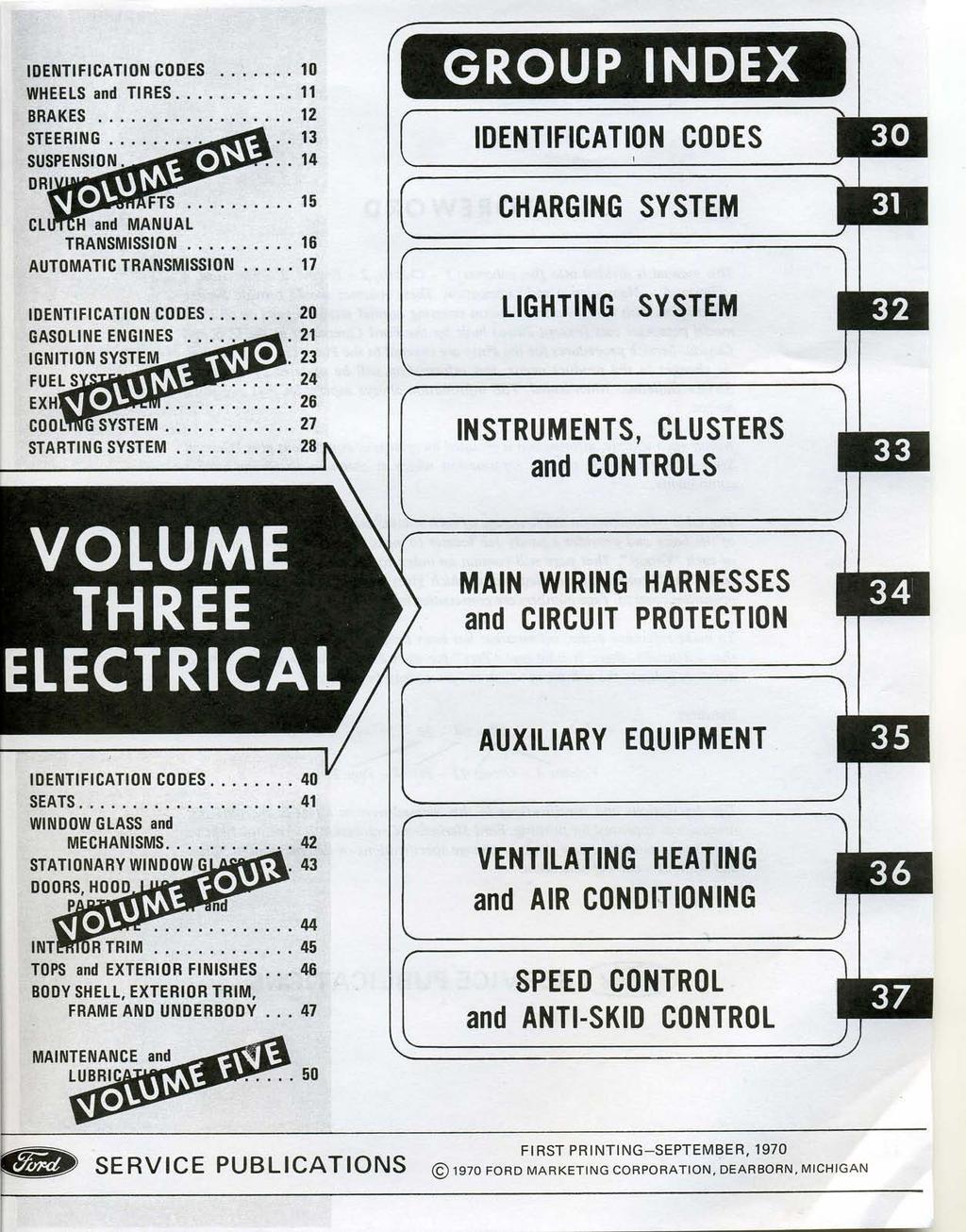
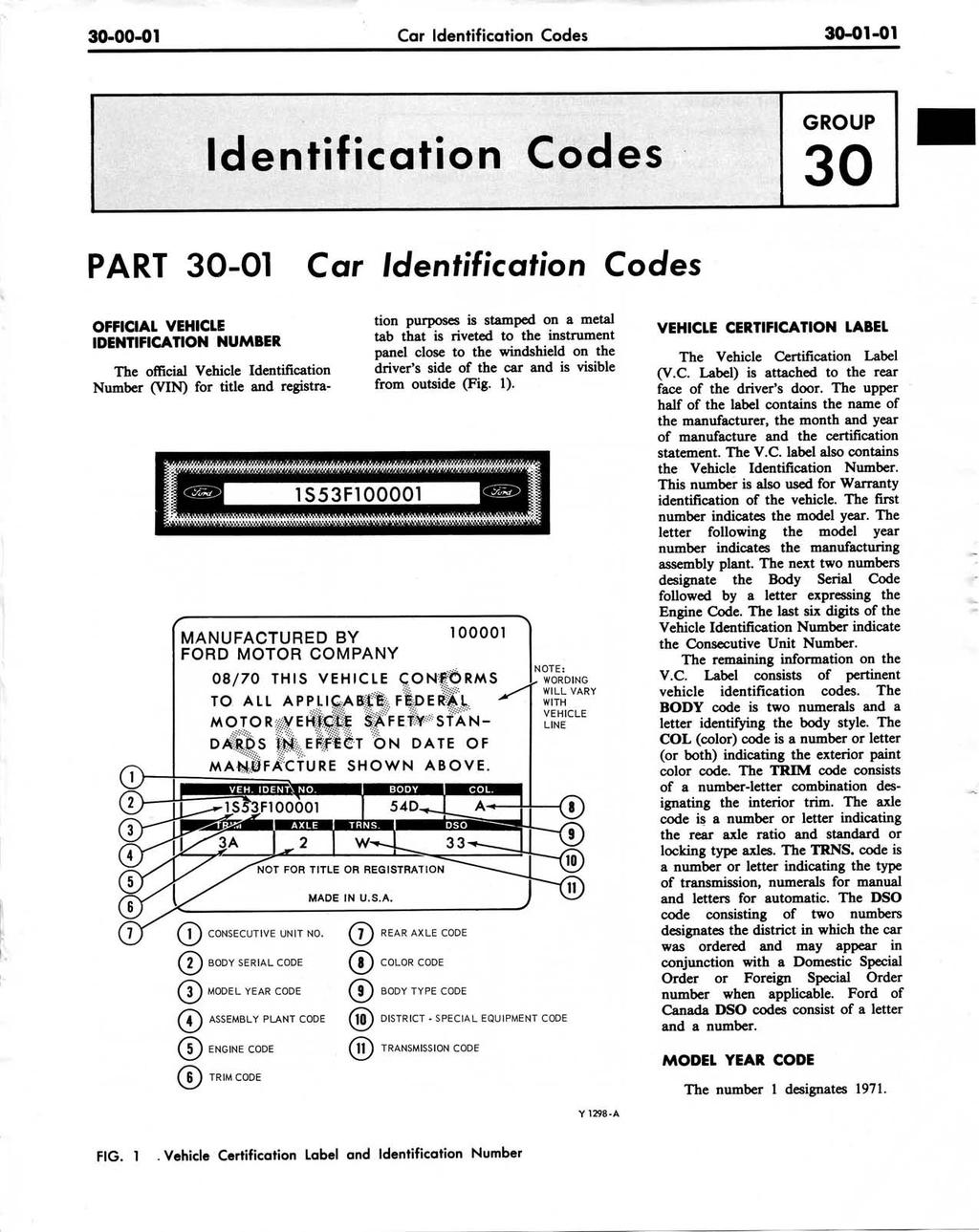
29 Charging System General Service WITH 55 AND 65-AMPERE ALTERNATORS C9AZ E (BLACK) USED. C9AZ E. VEHICLE EQUIPMENT SPLICE BATTERY TERMINAL FUSE LINK C9AZ D (GREEN) 0 THE RIGHT ABOVE THE VEHICLE EQUIPMENT TERMINAL TO VEHICLE FORD, MEROJRY. METEOR. FAIRLANE, FALCON, MONTEGO AND MAVERICK COUGAR, MUSTANG FIG. 1 Fuse Link Installation 2 TESTING CHARGING SYSTEM The alternator and alt-tor regulator are precision built units, and the equipment to make tests in the charging system must be accurate. Voltmeters must be accurate within 0.1 (one tenth) volt within the range of 12 to 16 volts and ammeters within one ampere at 30 to 65 amperes to permit correct measurement of the alternator and regulator. The meters on Rotunda equipment should be calibrated once a year and the date of calibration stamped on the meter face. It is recommended-that this practice be followed by technicians with other than approved equipment in order to maintain their meters at acceptable accuracy. Certain tests outlined. in this section are illustrated in schematic and in pictorial form. The schematic illustrates the internal connections of the Rotunda equipment so that these connections can be duplicated when this equipment is not available. The Rotunda test units are a combination of accepted instruments incorporated into a single unit. The various circuits involved in the tests can be selected by means of switches without the. necessity of changing connections. This reduces the time required to test ' units and circuits on the vehicle. ' Where applicable, the tests are divided into On The Vehicle and On The Test Bench procedures. Either procedure can be followed depending on the equipment available for the tests. Trouble shooting or diagnosis is required before actual repairs can be made in the electrical system. Even where an obvious fault makes the replacement of a unit necessary, you must still find out why the unit failed. The trouble shooting procedures given in the Electrical Systems Diagnosis Manual will aid in making a comt diagnosis. When a trouble is diagnosed correctly, unnecessary repairs are prevented, the time the vehicle is out of service will be decreased, and the i repairs that are m de will be permanent. the alternator, make turned out. that the 4 REMOVAL AND INSTALLATION FUSE LINK REPLACEMENT 1. Procure the proper service fuse stud on one end. When the terminal is not required, cut off the fuse Link as 2. cable. I Disconnect the attery ground link for the vehicle being repaired close to the te- as possible and \(Fig. 1). The two huc links shown strip approximately 3/8-inch of imuhave an eyelet terminal for a 5/ldinch htion from the cut end. andlor huc Link \.
30 Charging System General Service relay. On the Thunderbird, Lincoln Continental and the Continental Mark 111, the fuse link is looped outside of the wire harness behind the point at which the harness is clipped to the right rocker cover above the starter. 4. Cut the fuse link and the splice(s) from the wire(s) to which it is 6. Securely connect the eyelet attached. terminals (if any) to the battery stud 5. Splice and solder the new fuse on the starter relay. link to the wire(s) from which the old 7. Install the repaired wiring as link was cut. Use rosin core solder. before using existing clips if provided. Wrap the splice(s) completely with 8. Connect the ground cable to vinyl electricians tape. the battery.

31 S 1965/72 FORD CAR FINAL ISSUE Form and Acc ccesc essori 7 so ories CATA TALOG ALFLO LO m FP Source cecdo ADocument ccntn Ford Publication Form FP-7635-B s7 so6 B 5236 May, 1975 FINAL ISSUE COPYRIGHT FORD MOTOR -- DEARBORN, MICHIGAN COMPANY
32
33
34


35 HOW TO READ WIRING DIAGRAMS VOL 68 S7 L2A
36
37

38
39
40
Copyright 2009, Forel Publishing Company, LLC, Woodbridge, Virginia
 Copyright 2009, Forel Publishing Company, LLC, Woodbridge, Virginia All Rights Reserved. No part of this book may be used or reproduced in any manner whatsoever without written permission of Forel Publishing
Copyright 2009, Forel Publishing Company, LLC, Woodbridge, Virginia
 Copyright 2009, Forel Publishing Company, LLC, Woodbridge, Virginia All Rights Reserved. No part of this book may be used or reproduced in any manner whatsoever without written permission of Forel Publishing
Copyright 2009, Forel Publishing Company, LLC, Woodbridge, Virginia
 Copyright 2009, Forel Publishing Company, LLC, Woodbridge, Virginia All Rights Reserved. No part of this book may be used or reproduced in any manner whatsoever without written permission of Forel Publishing
Copyright 2009, Forel Publishing Company, LLC, Woodbridge, Virginia
 Copyright 2009, Forel Publishing Company, LLC, Woodbridge, Virginia All Rights Reserved. No part of this book may be used or reproduced in any manner whatsoever without written permission of Forel Publishing
Copyright 2009, Forel Publishing Company, LLC, Woodbridge, Virginia
 Copyright 2009, Forel Publishing Company, LLC, Woodbridge, Virginia All Rights Reserved. No part of this book may be used or reproduced in any manner whatsoever without written permission of Forel Publishing
Copyright 2009, Forel Publishing Company, LLC, Woodbridge, Virginia
 Copyright 2009, Forel Publishing Company, LLC, Woodbridge, Virginia All Rights Reserved. No part of this book may be used or reproduced in any manner whatsoever without written permission of Forel Publishing
Copyright 2009, Forel Publishing Company, LLC, Woodbridge, Virginia
 Copyright 2009, Forel Publishing Company, LLC, Woodbridge, Virginia All Rights Reserved. No part of this book may be used or reproduced in any manner whatsoever without written permission of Forel Publishing
Copyright 2009, Forel Publishing Company, LLC, Woodbridge, Virginia. Forel Publishing Company, LLC 3999 Peregrine Ridge Ct. Woodbridge, VA 22192
 Copyright 2009, Forel Publishing Company, LLC, Woodbridge, Virginia All Rights Reserved. No part of this book may be used or reproduced in any manner whatsoever without written permission of Forel Publishing
2018 Product Catalog
 2018 Product Catalog Prepared by David LeBlanc Forel Publishing Company, LLC (703) 772-8081 sales@forelpublishing.com As of January 1st, 2018 Forel Publishing Company, LLC The Leader in Digital Publishing
2017 Product Catalog
 2017 Product Catalog Prepared by David LeBlanc Forel Publishing Company, LLC (703) 772-8081 sales@forelpublishing.com As of January 1st, 2017 Forel Publishing Company, LLC The Leader in Digital Publishing
Note from the Publisher
 Copyright 2014, Forel Publishing Company, LLC, Woodbridge, Virginia All Rights Reserved. No part of this book may be used or reproduced in any manner whatsoever without written permission of Forel Publishing
1970 Ford Car Shop Manual READ ONLINE
 1970 Ford Car Shop Manual READ ONLINE If you are searching for a ebook 1970 ford car shop manual in pdf form, then you have come on to correct website. We presented full variant of this ebook in epub,
INSTRUCTIONS Circuit Wiring Kit Instructions _2017. Fuse Box Connections. (viewed from underside) 2018, Speedway Motors, Inc.
 2018, Speedway Motors, Inc.") Fuse Box Connections (viewed from underside) 4D 4C 100 50 300 4D 4C 4B 4A 43 107 39 103 3B 2G 104 93 2F 2E 2D 2C 2B 40 69A 102 101 105 2G 2F 2E 3A A 2A B 40A,B 27 69A 106 201, Speedway Motors, Inc. 1 Fuse
Fuse Box Connections (viewed from underside) 4D 4C 100 50 300 4D 4C 4B 4A 43 107 39 103 3B 2G 104 93 2F 2E 2D 2C 2B 40 69A 102 101 105 2G 2F 2E 3A A 2A B 40A,B 27 69A 106 201, Speedway Motors, Inc. 1 Fuse
40A A 40B. Horn Relay Connector. Brake Switch. Third Brake Light. Brake Switch. Brake Switch. Wires. page 3. Rear Body Feed Wires.
 Fuse Box Connections (viewed from underside) 4D 4C 4D 0 50 300 4C 43 7 39 3 6 4 93 A 2G 2F 2E 2D 2C 2B 2G 2F 2E 40 69A 2 1 5 27 69A 3A B 40A,B 11A,B 40A 156 Dimmer Dome Feed page 2 Horn Relay 2D 2 29 40B
Do-It-Yourself Battery Pack
 Do-It-Yourself Battery Pack 1 Page D I S C L A I M E R O F L I A B I L I T Y A N D W A R R A N T Y This publication describes the author s opinions regarding the subject matter herein. The author and publisher
MOTORCYCLE SECURITY 866F UNIVERSAL WIRING HARNESS All Rights Reserved. Ver. 1.3, Sep 06
 MOTORCYCLE SECURITY 866F UNIVERSAL WIRING HARNESS 2006 All Rights Reserved Ver. 1.3, Sep 06 Thank you for purchasing this CYCLONE Paging System. Please familiarize yourself with the content of this Guide
Battery Control Center - Diesel
 Service Manual CAUTION: All servicing of the Battery Control Center should be done only by a qualified Service Technician. Inadvertent shorts inside the Battery Control Center could result in severe damage
PPT RH: REDUCTANT HEATER (6.7L DIESEL) 2011 PCED 6.7L Diesel SECTION 5: Pinpoint Tests Procedure revision date: 02/25/2014
 2011 PCED 6.7L Diesel SECTION 5: Pinpoint Tests Procedure revision date: 02/25/2014") PPT RH: REDUCTANT HEATER (6.7... PPT RH: REDUCTANT HEATER (6.7L DIESEL) 2011 PCED 6.7L Diesel SECTION 5: Pinpoint Tests Procedure revision date: 02/25/2014 RH: Reductant Heater RH: Introduction RH1 PRELIMINARY
PPT RH: REDUCTANT HEATER (6.7... PPT RH: REDUCTANT HEATER (6.7L DIESEL) 2011 PCED 6.7L Diesel SECTION 5: Pinpoint Tests Procedure revision date: 02/25/2014 RH: Reductant Heater RH: Introduction RH1 PRELIMINARY
INSTRUCTIONS 12 Circuit Wiring Kit Instructions
 Fan 47 9 56 4 7 6 72 40 45 48 5 8 6 Gauge Power Temp Sender Headlight Power Power Radio Constant Power Instruments and Dash Rear of Vehicle Ignition and Lights Fuse Panel & Front of Vehicle Horn Alt Excitor
CHILTON FORD SERVICE MANUAL
 3154_U00.qxd 8/1/03 7:25 AM Page i CHILTON FORD SERVICE MANUAL 2004 Edition Australia Canada Mexico Singapore Spain United Kingdom United States 3154_U00.qxd 8/1/03 7:25 AM Page ii 3154_U00.qxd 8/1/03
12 Volt Utility Controller for 4, 6 or 8 Brakes No P
 12 Volt Utility Controller for 4, 6 or 8 Brakes No. 1300-77 P-1379 819-0094 Installation Instructions Introduction The Warner Electric manually operated Utility Controller operates 4, 6, or 8 twelve-volt
1962 Wiring Diagram. The Basics Part One. by Bob Mannel
 The Basics Part One 1962 Wiring Diagram by Bob Mannel Most restorers fear the wiring probably since it seems to be the most abused system in our Fairlanes. With cuts, splices, and extra wires running hither
Mazda North American Operations Irvine, CA
 Service Bulletin Mazda North American Operations Irvine, CA 92618-2922 Subject: REMOTE START CAUSES HVAC1 OR IGN1 FUSE TO BLOW - INSTALL LOAD REDUCTION RELAY SERVICE HARNESS Bulletin No: 01-046/08 2007-2008
PHILIPS TECHNICAL LIBRARY ELECTRICITY IN CARS R. H. BACON. Second Edition
 PHILIPS TECHNICAL LIBRARY ELECTRICITY IN CARS R. H. BACON Second Edition M N. V. Philips' Gloeilampenfabrieken, Eindhoven, 1967, 1975, 1976 A II rights reserved. No part of this publication may be reproduced
 D I S C L A I M E R O F L I A B I L I T Y A N D W A R R A N T Y This publication describes the author s opinions regarding the subject matter herein. The author and publisher are not rendering advice or
DP: Vehicle Speed Sensor (VSS)/Transfer Case Speed Sensor (TCSS) DP: Introduction
/Transfer Case Speed Sensor (TCSS) DP: Introduction") PPT DP: VEHICLE SPEED SENSOR... PPT DP: VEHICLE SPEED SENSOR ()/TRANSFER CASE SPEED SENSOR (TCSS) (GASOLINE ENGINES) 2005 PCED Gasoline Engines SECTION 5: Pinpoint Tests Procedure revision date: 03/30/2005
PPT DP: VEHICLE SPEED SENSOR... PPT DP: VEHICLE SPEED SENSOR ()/TRANSFER CASE SPEED SENSOR (TCSS) (GASOLINE ENGINES) 2005 PCED Gasoline Engines SECTION 5: Pinpoint Tests Procedure revision date: 03/30/2005
POWER DOOR LOCK CONTROL
 BE96 POWER DOOR LOCK CONTROL SYSTEM PARTS LOCATION BE97 WIRING AND CONNECTOR DIAGRAM BE98 TROUBLESHOOTING You will find the troubles easier using the table well shown below. In this table, each number
FORM # PRINTED IN U.S.A. PAGE 1 OF 11
 FORM #33002.08-010507 PRINTED IN U.S.A. PAGE 1 OF 11 SUPERLIFT SUSPENSION SYSTEMS 300 Huey Lenard Loop Rd. West Monroe, Louisiana 71292 Phone: (318) 397-3000 Sales / Tech: 1-800-551-4955 FAX: (318) 397-3040
EasyStart 364 (ASY-364-X20-IP) Installation Instructions for the Coleman / Airxcel Air Conditioners
 Installation Instructions for the Coleman / Airxcel Air Conditioners") EasyStart 364 (ASY-364-X20-IP) Installation Instructions for the Coleman / Airxcel Air Conditioners using Installation Kit KIT-364-CM1 Contents Introduction... 2 Safety first... 2 Making a good crimp...
EasyStart 364 (ASY-364-X20-IP) Installation Instructions for the Coleman / Airxcel Air Conditioners using Installation Kit KIT-364-CM1 Contents Introduction... 2 Safety first... 2 Making a good crimp...
INSTRUMENT PANEL AND GAUGES INSTRUMENT PANEL AND GAUGES XJ
 J INSTRUMENT PANEL AND GAUGES 8E - 1 INSTRUMENT PANEL AND GAUGES GROUP INDEX INSTRUMENT PANEL AND GAUGES XJ... 1 INSTRUMENT PANEL AND GAUGES YJ... 24 INSTRUMENT PANEL AND GAUGES XJ CONTENTS page DIAGNOSIS...
CAPACITOR ACTUATED PORTABLE STARTER CAPS USER GUIDE. INST048 Doc 3.01
 CAPACITOR ACTUATED PORTABLE STARTER CAPS USER GUIDE INST048 Doc 3.01 CONTENTS General Information...2 Charts...3 Before First Use...4 Safety Requirements...5 What to Expect from the CAPS...5 CAPS Diagram...6
NUMBER: GROUP: DATE: November 12, 2005 SUBJECT: OVERVIEW: MODELS: SYMPTOM/CONDITION: REV A. Electrical
 NUMBER: GROUP: 08-036-05 REV A Electrical DATE: November 12, 2005 This bulletin is supplied as technical information only and is not an authorization for repair. No part of this publication may be reproduced,
Installing the Throttle Commander Ford F250 F550 Super Duty
 Installing the Throttle Commander Ford F250 F550 Super Duty 7.3L Power Stroke Diesel 1996 up to 2001.25 T500011 and T500028 1.0 Preparing for Installation...5 2.0 Installing the Throttle Controller...5
MAINFRAME HOT RUNNER TEMPERATURE CONTROL SYSTEMS. Instruction Manual
 MAINFRAME HOT RUNNER TEMPERATURE CONTROL SYSTEMS Instruction Manual Copyright, Athena Controls, Inc., 2006 Printed in USA CompuStep is a registered trademark of Athena Controls, Inc. SafeChange is a trademark
60 PSI Boost Gauge. For Product Numbers: MT-DV01_60, MT-WDV01_60
 60 PSI Boost Gauge For Product Numbers: MT-DV01_60, MT-WDV01_60 Red: 12v Constant (un-switched) Source (+) Orange: 12v Dimmer (switched) Source (+) (optional) White: 12v Ignition (switched) Source (+)
 Page 1 of 29 Section 04-05: Suspension, Computer Controlled 1997 Town Car Workshop Manual DIAGNOSIS AND TESTING Procedure revision date: 05/16/2000 Suspension, Computer Controlled Inspection and Verification
Utility Controller Hand Air Operated
 Utility Controller Hand Air Operated P-1395 819-0288 Installation Instructions Introduction The Warner Electric air/manual Utility Controller combines manual and automatic (air) actuation for the operation
EasyStart Installation Instructions for Dometic Family RV A/Cs
 EasyStart Installation Instructions for Dometic Family RV A/Cs DuoTherm Brisk Brisk II Penguin Penguin II Contents Introduction... 4 Safety first... 4 Making a good crimp... 4 Identifying Dometic AC Units...
INSTRUCTIONS. 20 Circuit Wiring Kit Instructions October 2009, Speedway Motors, Inc.
 1 MAIN FUSE PANEL The main fuse panel harness s designed to be mounted under the dash a the firewall in an area close to the steering column. The enclosed representation of the main dash harness shows
12 Volt Utility Controller for 4, 6, or 8 Brakes No
 12 Volt Utility Controller for 4, 6, or 8 Brakes No. 1300-76 P-1396-WE 819-0301 Installation Instructions An Altra Industrial Motion Company Contents Introduction... 2 Installation... 3 Mounting Under
EROAD Inspect DVIR. Addendum to the EROAD ELD User Manual
 EROAD Inspect DVIR Addendum to the EROAD ELD User Manual PREFACE This addendum is a supplement to the EROAD ELD User Manual, which may be updated at any time. See EROAD.com for the latest version of EROAD
05/01/06 1er mai 2006 Cruise Control - Diagnostic Updates General Service Procedure Service Procedure Speed Control Diagnostic Tips Additional
 05/01/06 1er mai 2006 General Service Procedure Service Procedure Speed Control Diagnostic Tips Additional Reference Information SPEED CONTROL DIAGNOSTICS - W/O SCP FORD: 2000-2003 Escort 2000-2004 Crown
Classic Update Series
 Classic Update Series 1964-1966 Ford Mustang START HERE! PLEASE READ THIS EFORE STARTING INSTALLATION! This wiring kit is designed for ease of installation. Please read the guidelines below, EFORE STARTING
Solar-Powered Battery Bank
 Solar-Powered Battery Bank 1 Page D I S C L A I M E R O F L I A B I L I T Y A N D W A R R A N T Y This publication describes the author s opinions regarding the subject matter herein. The author and publisher
ASSEMBLY OPERATIONS MANUALS COLLECTION, Accession 1766
 Finding Aid for ASSEMBLY OPERATIONS MANUALS COLLECTION, 1959-1988 Finding Aid Published: January 2011 20900 Oakwood Boulevard Dearborn, MI 48124-5029 USA research.center@thehenryford.org www.thehenryford.org
jegs.com
 Contents Wiring Harness w/ Fuse Panel Installation Instructions Turn Signal Plug w/ Terminals 2 Headlight Plugs 3/4 Grommet 10 ¼ Terminals 4 Ring Terminals 10 Wire Ties Fusible Link 2 Screws & Nuts 2 Plastic
Installation Instructions for the Plug & Play Chrysler/Dodge/Jeep Remote Start Package w/mux T5
 v1.01 12/14/2102 Installation Instructions for the Plug & Play Chrysler/Dodge/Jeep Remote Start Package w/mux T5 Review the remote start installation manual for safety instructions! Overview Your kit consists
FORD CAR-TRUCK FORD MOTOR COMPANY FORD DIVISION
 FORD CAR-TRUCK FORD DIVISION FORD MOTOR COMPANY Copyright 2010, Forel Publishing Company, LLC, Woodbridge, Virginia All Rights Reserved. No part of this book may be used or reproduced in any manner whatsoever
1993 Ford Escort. G - TESTS W/CODES - EEC-IV (1.9L)' '1993 ENGINE PERFORMANCE Ford Motor Co. - Self-Diagnostics - EEC-IV
' '1993 ENGINE PERFORMANCE Ford Motor Co. - Self-Diagnostics - EEC-IV") CIRCUIT TEST J - FUEL PUMP CIRCUIT (RELAY & INERTIA SWITCH) Diagnostic Aids When ignition switch is in the ON or START position, the PCM connects FUEL PUMP circuit (PCM terminal No. 22) to ground. The
CIRCUIT TEST J - FUEL PUMP CIRCUIT (RELAY & INERTIA SWITCH) Diagnostic Aids When ignition switch is in the ON or START position, the PCM connects FUEL PUMP circuit (PCM terminal No. 22) to ground. The
Installation Tips for your Remote Start/Keyless Entry (for Honda/Acura Vehicles) [EVO-ALL] v1.02 updated 9/13/2013
![Installation Tips for your Remote Start/Keyless Entry (for Honda/Acura Vehicles) [EVO-ALL] v1.02 updated 9/13/2013](/thumbs/87/96035180.jpg "Installation Tips for your Remote Start/Keyless Entry (for Honda/Acura Vehicles) [EVO-ALL] v1.02 updated 9/13/2013") Installation Tips for your Remote Start/Keyless Entry (for Honda/Acura Vehicles) [EVO-ALL] v1.02 updated 9/13/2013 Thank you for purchasing your remote start from MyPushcart.com - an industry leader in
Installation Tips for your Remote Start/Keyless Entry (for Honda/Acura Vehicles) [EVO-ALL] v1.02 updated 9/13/2013 Thank you for purchasing your remote start from MyPushcart.com - an industry leader in
SELECT DIAGNOSTIC GUIDE. INST028 Doc 3.02
 SELECT DIAGNOSTIC GUIDE INST028 Doc 3.02 CONTENTS General Information...2 Select Call-Outs...3 Wire Diagram and Legend...4 Diagnostics...6 Excessive Voltage Drop Diagnostics...6 Static Diagnostics...7
Fuse/Relay Information
 BD 10/24/91 kd 11/12 smk 11/14/91 MC 4/8/92 bd 4/14/92 92 PRELUDE /Relay Information Under-hood /Relay Box 47 46 45 44 43 42 41 40 39 31 49 48 51 50 37 36 35 34 33 32 C941 (To ABS motor relay) 38 C942
RS4 / RS7 + (4) + SPDT
 + SPDT") TIP SHEET Installation Tips for RS4 / RS7 + Honda-SL3 (4) + SPDT + Diode x2 T0776, T0731 Honda: ( 08-12 Accord), ( 12-13 Civic), 12-13 CRV), ( 11-13 Odyssey), ( 09-13 Pilot) Acura: ( 09-13 TSX) Thank you
TIP SHEET Installation Tips for RS4 / RS7 + Honda-SL3 (4) + SPDT + Diode x2 T0776, T0731 Honda: ( 08-12 Accord), ( 12-13 Civic), 12-13 CRV), ( 11-13 Odyssey), ( 09-13 Pilot) Acura: ( 09-13 TSX) Thank you
Gateway 505/605 Symptom Flow Chart Lift Interlock
 An ISO 9001:2008 Registered Company Gateway 505/605 Symptom Flow Chart Lift Interlock Begin diagnosis by performing the system post installation instructions notating system operation while doing checks.
1965/72 FORD CAR CATALOG FINAL ISSUE. Master Parts and Accessories. Form FP 7635-A & B. Supersends All Previous Issues, Changes and Revisions
 1965/72 FORD CAR FINAL ISSUE Master Parts and Accessories CATALOG Form FP 7635-A & B Supersends All Previous Issues, Changes and Revisions May, 1975 FINAL ISSUE COPYRIGHT 1975 -- FORD MOTOR -- DEARBORN,
UNISTEER Performance Products UNIVERSAL HOT ROD ELECTRA-STEER KIT
 UNISTEER Performance Products UNIVERSAL HOT ROD ELECTRA-STEER KIT 8051500 BEFORE YOU START PLEASE READ! Designing steering systems requires an understanding of steering function and design. If you are
TELORVEK EFI 5.0 Coyote Sequential Fuel Injection System Part # CY-11
 Page #1 TELORVEK EFI 5.0 Coyote Sequential Fuel Injection System Part # CY-11 WIRING INSTRUCTIONS Thank you for purchasing the absolute finest of wiring kits for the Ford Motor Co. Coyote modular engine.
Ford Shop Tips Volume 1, Number 1 Volume 1, Number 2
 Ford Shop Tips magazine was a Ford technical service publication sent to mechanics at the dealership and in service stations and independent garages to help with the servicing of Ford vehicles. This technical
TIP SHEET T2352, T3396. Installation Tips for RS1 + EVO-ALL 1-BUTTON REMOTE STARTER FOR: Acura RDX PUSH-TO-START / AUTOMATIC
 Installation Tips for RS1 + EVO-ALL 1-BUTTON REMOTE STARTER FOR: Acura RDX 2013-2015 PUSH-TO-START / AUTOMATIC TIP SHEET T2352, T3396 Thank you for purchasing your remote start from MyPushcart.com - an
 Page 1 of 50 Section 412-00: Climate Control System General Information DIAGSIS AND TESTING 1997 Mark VIII Workshop Manual Climate Control System Special Service Tool(s) 73 Digital Multimeter 105-R0051
MY F150 CrewCab 1. Tools Required E F G. Page 1 of 10 9L3J-19A014-AA Copyright Ford 2013 FoMoCo
 2009-2014MY F150 CrewCab 1 Tools Required A B C D 3X E F G H 2X I 6X 3X Page 1 of 10 9L3J-19A014-AA Copyright Ford 2013 FoMoCo 2009-2014MY F150 CrewCab 2 Subwoofer Power Wire Routing All Vehicles WARNING:
STARTING SYSTEMS 8B - 1 STARTING SYSTEMS CONTENTS
 TJ STARTING SYSTEMS 8B - 1 STARTING SYSTEMS CONTENTS page DESCRIPTION AND OPERATION STARTER MOTOR... 2 STARTER RELAY... 3 STARTING SYSTEM... 1 DIAGNOSIS AND TESTING STARTER MOTOR... 8 STARTER MOTOR NOISE
TIP SHEET. Installation Tips for your RS OL-MDB-CH6 (1) (for Jeep vehicles) T1227 v1.0 3/19/14
 (for Jeep vehicles) T1227 v1.0 3/19/14") TIP SHEET Installation Tips for your RS-360 + OL-MDB-CH6 (1) (for Jeep vehicles) T1227 v1.0 3/19/14 Thank you for purchasing your remote start from MyPushcart.com - an industry leader in providing remote
TIP SHEET Installation Tips for your RS-360 + OL-MDB-CH6 (1) (for Jeep vehicles) T1227 v1.0 3/19/14 Thank you for purchasing your remote start from MyPushcart.com - an industry leader in providing remote
PBS M Marine Push Button Start
 PBS M Marine Push Button Start INSTALLATION & USER GUIDE PBS M CONTENTS The following list of components are included in this system: 1 Push Button Start & RFID Reader 1 PBS Harness Pack 1 RFID Antenna
Using the PST-2000 with Freightliner Trucks. Document Number B
 Using the PST-2000 with Freightliner Trucks Document Number Every effort has been made to keep the information in this document current and accurate as of the date of publication or revision. However,
Installation of Triple A-Pillar Pod and 7 Series Diesel Gauges Dodge Ram w/ 12 Valve Cummins Diesel Engine
 Installation of Triple A-Pillar Pod and 7 Series Diesel Gauges 1994-1997 Dodge Ram w/ 12 Valve Cummins Diesel Engine GlowShift strives to provide outstanding technical support, and our technical support
Occupant Classification Sensor
 SECTION 501-20B: Supplemental Restraint System 2009 Mustang Workshop Manual REMOVAL AND INSTALLATION Procedure revision date: 05/23/2008 Occupant Classification Sensor Special Tool(s) Vehicle Communication
750 Paso Wiring Upgrade
 750 Paso Wiring Upgrade Supplies required: 2 Bosch 30A/12V Relays # #0 332 209 150 (with mounting tab) 1 30 Amp fuse holder 1 10 Amp fuse holder 12 inches of brown 12 gauge wire 60 inches of red 14 gauge
ALTERNATOR - BOSCH 35/75-AMP & 40/90-AMP
 ALTERNATOR - BOSCH 35/75-AMP & 40/90-AMP 1988 Chrysler LeBaron Convert/Coupe 1988 ALTERNATORS & REGULATORS Chrysler Motors - Bosch 35/75 & 40/90 Amp Alternator All Models DESCRIPTION The charging system
with lcd display 12-42v
 instructions for: AUTO PROBE with lcd display 12-42v MODEL No: PP7 Thank you for purchasing a Sealey product. Manufactured to a high standard this product will, if used according to these instructions
Installing Ignition Coil relay
 Installing Ignition Coil relay Above is a schematic diagram of the coil relay modification. All it really does is, it uses the existing 12 Volt positive that normally powers the coils, to power a relay,
72 Mustang Mach 1 tachometer cluster and gauge conversion
 72 Mustang Mach 1 tachometer cluster and gauge conversion Dated: 02-17-2009 (drafted by a Chevy person working on his first Ford -not good-) Revised: 11-05-2010 The following information pertains to how
RB12 AERO - DUAL INSTALLATION MANUAL. February 2017
 RB12 AERO - DUAL INSTALLATION MANUAL February 2017 CONTENTS February 2016 This manual is to be read in conjunction with the Product Specifications & Assembly manual SECTION NO. DESCRIPTION PAGE NO. SECTION
ODY-05-2 VOLTMETER FOR REMOTE MONITORING
 ODY-05-2 VOLTMETER FOR REMOTE MONITORING Introduction: The Odyssey gauge series from Dakota Digital, Inc. incorporates the reliability and quality of our standard gauges, along with several unique features
ALTERNATOR - CHRYSLER 40/90-AMP & 50/120 AMP
 ALTERNATOR - CHRYSLER 40/90-AMP & 50/120 AMP 1988 Chrysler LeBaron Convert/Coupe 1988 ELECTRICAL Chrysler Motors 40/90 & 50/120 Amp Alternators FWD Models DESCRIPTION The charging system consists of an
Mazda North American Operations Irvine, CA
 Service Bulletin Mazda North American Operations Irvine, CA 92618-2922 Subject: STARTER MOTOR WILL NOT CRANK AND ENGINE DOES NOT START (INTER- MITTENTLY) Bulletin No: 01-037/08 2004-2008 MAZDA3 - STARTER
TIP SHEET T0937. Installation Tips For RS00/PS00 + ADS-TBSL-PL + SPDT
 Installation Tips For RS00/PS00 + ADS-TBSL-PL + SPDT TIP SHEET T0937 Thank you for purchasing your remote start from MyPushcart.com - an industry leader in providing remote starts to do-it-yourself installers
HORN OPERATION DIAGNOSIS MOST GM VEHICLES 1967 AND UP
 Revised: 27OC2010 HORN OPERATION DIAGNOSIS MOST GM VEHICLES 1967 AND UP All General Motors vehicles (from the 60s through the 80s) have a horn or horns that operate on the same basic principle. When you
Using the PST-2000 with Peterbilt Trucks. Document Number B
 Using the PST-2000 with Peterbilt Trucks Document Number Every effort has been made to keep the information in this document current and accurate as of the date of publication or revision. However, no
Series 1000 and Figure NOTE: The top terminals are showing normally closed at rest and the middle terminals are normally
 38.18.The red wire on the OCR plug carries battery voltage. Behavior: D.C. battery voltage should show-up on a volt meter when the red probe is touched to this terminal and the black probe is grounded,
1999 Mercury Cougar ACCESSORIES & EQUIPMENT' 'Passive Anti-Theft Systems - Cougar 1999 ACCESSORIES & EQUIPMENT
 DESCRIPTION 1999 ACCESSORIES & EQUIPMENT Passive Anti-Theft Systems - Cougar Passive Anti-Theft System (PATS) is available on some vehicles. The system is passive in that it does not require any activity
EasyStart. 364 (3 ton) Soft Starter 368 (6 ton) Soft Starter. Installation Manual
 Soft Starter 368 (6 ton) Soft Starter. Installation Manual") EasyStart 364 (3 ton) Soft Starter 368 (6 ton) Soft Starter Installation Manual Micro-Air Corporation www.microair.net 124 Route 526 Phone (609) 259-2636 Allentown NJ 08501 Fax (609) 259-6601 Retrofit
EasyStart 364 (3 ton) Soft Starter 368 (6 ton) Soft Starter Installation Manual Micro-Air Corporation www.microair.net 124 Route 526 Phone (609) 259-2636 Allentown NJ 08501 Fax (609) 259-6601 Retrofit
2002 Jeep Grand Cherokee Limited
 Remove the two nuts that secure the instrument panel wire harness ground eyelets to the studs on the floor panel transmission tunnel in front of and behind the ACM. Disengage the retainers that secure
MODEL No s: PP3, PP3K
 instructions for: Power PROBE 3 12-24v MODEL No s: PP3, PP3K Thank you for purchasing a Sealey product. Manufactured to a high standard this product will, if used according to these instructions and properly
REC-11+ REMOTE RECEIVER UNIT
 Resetting The Programmable Features The installer may quickly and easily return all 17 programmable features back to the factory settings. Changing individual features were explained in detail in the previous
REMOTE CENTRAL LOCK. Model: CLRxxx-ULT
 REMOTE CENTRAL LOCK Model: CLRxxx-ULT Contents Remote Lock, Remote Unlock, Car Finder, Remote Boot release:, Power Window outoput, Learning Transmitter Codes... page 3 Wiring Diagram... page 4 Introduction,
SUBJECT: I/M Readiness Check Continues To Indicate OBD System Is Not Ready For I/M Testing
 NUMBER: 25-001-07 GROUP: Emissions DATE: February 09, 2007 This bulletin is supplied as technical information only and is not an authorization for repair. No part of this publication may be reproduced,
WIPER/WASHER SYSTEM - FRONT ACCESSORIES & EQUIPMENT General Motors Corp. - Front Wiper/Washer System
 WIPER/WASHER SYSTEM - FRONT 1998 ACCESSORIES & EQUIPMENT General Motors Corp. - Front Wiper/Washer System DESCRIPTION & OPERATION CAUTION: To prevent scratching, wet the windshield before turning on wipers.
2002 Ford Explorer STARTING & CHARGING SYSTEMS' 'Generators & Regulators - Explorer & Mountaineer STARTING & CHARGING SYSTEMS
 DESCRIPTION 2002-03 STARTING & CHARGING SYSTEMS Generators & Regulators - Explorer & Mountaineer System consists of generator, regulator, battery, fuses, PCM and associated wiring. Generators have an electronic
Installation Tips for your RS-1 + Honda-SL3 (1.b) Remote starter Honda: ( FIT), ( Pilot), ( Ridgeline) Acura: ( MDX)
 Remote starter Honda: ( FIT), ( Pilot), ( Ridgeline) Acura: ( MDX)") Installation Tips for your RS-1 + Honda-SL3 (1.b) Remote starter Honda: ( 06-08 FIT), ( 05-08 Pilot), ( 06-13 Ridgeline) Acura: ( 03-06 MDX) TIP SHEET T0777 Thank you for purchasing your remote start from
Installation Tips for your RS-1 + Honda-SL3 (1.b) Remote starter Honda: ( 06-08 FIT), ( 05-08 Pilot), ( 06-13 Ridgeline) Acura: ( 03-06 MDX) TIP SHEET T0777 Thank you for purchasing your remote start from
Installation Tips For Crimestopper RS7 + Passlock-sl2(4) + DLRM + SPDT
 + DLRM + SPDT") TIP SHEET T3628 Installation Tips For Crimestopper RS7 + Passlock-sl2(4) + DLRM + SPDT For Chevrolet: Astro 1998-2005, Avalanche 2002, Blazer 1998-2005, Cavalier 2000-2003, Express Van 1998-2005, S10 Pickup
TIP SHEET T3628 Installation Tips For Crimestopper RS7 + Passlock-sl2(4) + DLRM + SPDT For Chevrolet: Astro 1998-2005, Avalanche 2002, Blazer 1998-2005, Cavalier 2000-2003, Express Van 1998-2005, S10 Pickup
HA PRO INSTALLERʼS MANUAL. HA-008 v3. User s/installer s Manual
 HA-008 v3 HA - 280 PRO User s/installer s Manual INSTALLERʼS MANUAL Manufacturer: COMMERCIAL ELECTRONICS 264 HAYDONS ROAD, WIMBLEDON, LONDON SW19 8TT. UK TEL: +44 020 8404 7105 FAX: +44 020 8404 7104 http://www.hawkcaralarm.com
2000 Crown Victoria/Grand Marquis Workshop Manual
 Page 1 of 15 SECTION 501-16: Wipers and Washers 2000 Crown Victoria/Grand Marquis Workshop Manual DIAGNOSIS AND TESTING Procedure revision date: 06/21/1999 Wipers and Washers Refer to Wiring Diagrams Cell
Safety Sentry Electronic Breakaway Switch
 Safety Sentry Electronic Breakaway Switch P-616-WE 819-0454 Installation Instructions An Altra Industrial Motion Company Parts List Mounting hardware included with the Safety Sentry Breakaway Switch kit:
DESCRIPTION & OPERATION
 DESCRIPTION & OPERATION 2001 ACCESSORIES/SAFETY EQUIPMENT General Motors Corp. - Air Bag Restraint Systems WARNING: Accidental air bag deployment is possible. Personal injury may result. To avoid injury
Installation, Operating & Maintenance Instructions. HV angle valve with pneumatic actuator single acting with closing spring (NC)
") Installation, Operating & Maintenance Instructions HV angle valve with pneumatic actuator single acting with closing spring (NC) Series 264 DN 10 50 mm (I. D. ⅜" 2") HV inline valve with pneumatic actuator
Installation, Operating & Maintenance Instructions HV angle valve with pneumatic actuator single acting with closing spring (NC) Series 264 DN 10 50 mm (I. D. ⅜" 2") HV inline valve with pneumatic actuator
American National Standard for Lighting Equipment Voltage Surge Requirements
 American National Standard for Lighting Equipment Voltage Surge Requirements Secretariat: National Electrical Manufacturers Association Approved: December 21, 2017 American National Standards Institute,
WARNING: DO NOT USE HAND-HELD 2-WAY TRANSCEIVERS INSIDE YOUR VEHICLE WHILE DRIVING.
 CRC-1000 Drive-by-Wire Cruise Control System Introduction You have purchased one of the finest cruise control systems on the market. The cruise control features: Enhanced Adaptability Enhanced Features
3.4 AUXILIARY ACCESSORIES INSTRUCTIONS
 1 3.4 AUXILIARY ACCESSORIES INSTRUCTIONS # 48-10-01-001 - 3.4 Auxiliary Accessories www.teraflex.com Important Notes: Prior to beginning this or any installation read these instructions to familiarize
Condition. Correction
 #06-06-04-008B: LNJ Service Engine Soon (SES) Light On, Multiple Powertrain Control Module (PCM) Diagnostic Trouble Code (DTC) P1404 and/or P0404 (Install EGR Valve/Gasket/Pipe/Wiring Harness Connector,Reprogram