FORD RANGER Owner's Manual
|
|
|
- Claribel Copeland
- 5 years ago
- Views:
Transcription

1 FORD RANGER Owner's Manual
2 The information contained in this publication was correct at the time of going to print. In the interest of continuous development, we reserve the right to change specifications, design or equipment at any time without notice or obligation. No part of this publication may be reproduced, transmitted, stored in a retrieval system or translated into any language in any form by any means without our written permission. Errors and omissions excepted. Ford Motor Company 2014 All rights reserved. Part Number: DB AD (CG3575en) 09/
3 Table of Contents Introduction About This Manual...7 Symbols Glossary...7 Data Recording...9 Replacement Parts Recommendation...10 Special Notices...10 Mobile Communications Equipment...10 At a Glance Front Exterior Overview...12 Rear Exterior Overview...13 Vehicle Interior Overview...14 Instrument Panel Overview...15 Child Safety Installing Child Seats...18 Child Seat Positioning...21 Child Safety Locks...23 Safety Belts Principle of Operation...24 Fastening the Safety Belts...24 Safety Belt Height Adjustment...25 Safety Belt Minder...26 Supplementary Restraints System Principle of Operation...27 Driver Airbag...27 Passenger Airbag...28 Side Airbags...29 Driver Knee Airbag...29 Side Curtain Airbags...29 Keys and Remote Controls General Information on Radio Frequencies...31 Remote Control...31 Replacing a Lost Key or Remote Control...33 Security Passive Anti-Theft System...34 Anti-Theft Alarm...34 Locks Locking and Unlocking...36 Steering Wheel Adjusting the Steering Wheel...39 Audio Control...39 Voice Control...40 Cruise Control...40 Wipers and Washers Windshield Wipers...41 Autowipers...41 Windshield Washers...42 Lighting General Information...43 Lighting Control...43 Autolamps...44 Instrument Lighting Dimmer...44 Headlamp Exit Delay...44 Daytime Running Lamps...45 Front Fog Lamps...45 Rear Fog Lamps...46 Headlamp Leveling...46 Direction Indicators...47 Approach Lamps...47 Interior Lamps...47 Windows and Mirrors Power Windows...49 Interior Mirror...50 Exterior Mirrors
4 Table of Contents Sliding Windows...52 Instrument Cluster Gauges...53 Warning Lamps and Indicators...53 Audible Warnings and Indicators...57 Information Displays General Information...59 Clock...61 Trip Computer...61 Personalized Settings...63 Climate Control Principle of Operation...65 Air Vents...65 Manual Climate Control...66 Automatic Climate Control...68 Heated Windows and Mirrors...70 Seats Sitting in the Correct Position...72 Manual Seats...72 Power Seats...74 Head Restraints...76 Rear Seats...76 Heated Seats...78 Auxiliary Power Points Auxiliary Power Points...79 Cigar Lighter...79 Storage Compartments Cup Holders...80 Glove Box...80 Center Console...80 Cool Box...81 Ashtray...81 Glasses Holder...81 Rear Seat Armrest...81 Starting and Stopping the Engine General Information...82 Ignition Switch...82 Steering Wheel Lock...82 Starting a Gasoline Engine...83 Starting a Diesel Engine...84 Diesel Particulate Filter...84 Switching Off the Engine...85 Fuel and Refueling Safety Precautions...86 Fuel Quality...87 Fuel Quality...87 Running Out of Fuel...87 Catalytic Converter...88 Refueling...88 Fuel Consumption...90 Technical Specifications...91 Transmission Manual Transmission...93 Automatic Transmission...93 Four-Wheel Drive Principle of Operation...97 Using Four-Wheel Drive...97 Rear Axle Limited Slip Differential Electronic Locking Differential Brakes Principle of Operation Hints on Driving With Anti-Lock Brakes Parking Brake Hill Start Assist
5 Table of Contents Traction Control Principle of Operation Using Traction Control Stability Control Principle of Operation Using Stability Control Terrain Response Principle of Operation Using Hill Descent Control Parking Aids Principle of Operation Parking Aid Rear View Camera Cruise Control Principle of Operation Using Cruise Control Load Carrying General Information Luggage Covers Roof Racks and Load Carriers Load Retaining Fixtures Tailgate Towing Towing a Trailer Trailer Sway Control Recommended Towing Weights Tow Ball Towing Points Towing the Vehicle on Four Wheels Driving Hints Breaking-In General Driving Points Cold Weather Precautions Reduced Engine Performance Driving Through Water Floor Mats Roadside Emergencies Hazard Warning Flashers First Aid Kit Warning Triangle Jump Starting the Vehicle Fuses Fuse Box Locations Fuse Specification Chart Changing a Fuse Maintenance General Information Opening and Closing the Hood Under Hood Overview - 2.5L Duratec-HE (122kW/165PS) - MI Under Hood Overview - 2.2L Duratorq-TDCi (Puma) Diesel Under Hood Overview - 3.2L Duratorq-TDCi (Puma) Diesel Engine Oil Dipstick - 2.5L Duratec-HE (122kW/165PS) - MI Engine Oil Dipstick - 2.2L Duratorq-TDCi (Puma) Diesel/3.2L Duratorq-TDCi (Puma) Diesel Engine Oil Check Engine Coolant Check Power Steering Fluid Check Brake and Clutch Fluid Check Draining the Fuel Filter Water Trap Washer Fluid Check Changing the 12V Battery Checking the Wiper Blades Changing the Wiper Blades Changing a Bulb Bulb Specification Chart
6 Table of Contents Technical Specifications Vehicle Care Cleaning the Exterior Cleaning the Interior Repairing Minor Paint Damage Cleaning the Alloy Wheels Wheels and Tires General Information Using Winter Tires Using Snow Chains Changing a Road Wheel Technical Specifications Capacities and Specifications Vehicle Dimensions Towbar Dimensions Vehicle Identification Plate Vehicle Identification Number SYNC General Information Using Voice Recognition Using SYNC With Your Phone SYNC Applications and Services Using SYNC With Your Media Player SYNC Troubleshooting Navigation introduction General Information Road Safety Navigation Quick start Navigation Quick start Loading the navigation data System settings System settings Navigation system Route options menu Route displays Traffic Message Channel Principle of Operation Using TMC Map updates Map updates Audio introduction Important audio information Audio unit overview Audio unit overview Audio System Security Security code Audio Unit Clock and Date Displays Setting the clock on the audio unit Audio unit operation On/off control Sound button Waveband button Station tuning control Station preset buttons Autostore control Traffic information control Navigation unit overview Navigation unit overview
7 Table of Contents Audio unit menus Automatic volume control Digital signal processing (DSP) News broadcasts Alternative frequencies Regional mode (REG) Compact Disc Player Compact disc playback Track selection Fast forward/reverse Shuffle/random Repeat compact disc tracks Compact disc track scanning MP3 file playback MP3 display options Ending compact disc playback Auxiliary input jack Auxiliary input jack Audio system care Antenna Audio Troubleshooting Audio troubleshooting Appendices Type approvals Electromagnetic Compatibility
8 6


9 Introduction ABOUT THIS MANUAL Thank you for choosing Ford. We recommend that you take some time to get to know your vehicle by reading this manual. The more that you know about it, the greater the safety and pleasure you will get from driving it. WARNING Driving while distracted can result in loss of vehicle control, crash and injury. We strongly recommend that you use extreme caution when using any device that may take your focus off the road. Your primary responsibility is the safe operation of your vehicle. We recommend against the use of any hand-held device while driving and encourage the use of voice-operated systems when possible. Make sure you are aware of all applicable local laws that may affect the use of electronic devices while driving. Note: This manual describes product features and options available throughout the range of available models, sometimes even before they are generally available. It may describe options not fitted to the vehicle you have purchased. Note: Some of the illustrations in this manual may show features as used in different models, so may appear different to you on your vehicle. Note: Always use and operate your vehicle in line with all applicable laws and regulations. Note: Pass on this manual when selling your vehicle. It is an integral part of your vehicle. This manual may qualify the location of a component as left-hand side or right-hand side. The side is determined when facing forward in the seat. A B Right-hand side. Left-hand side. SYMBOLS GLOSSARY These are some of the symbols you may see on your vehicle. Safety alert See Owner's Manual Air conditioning system Anti-lock braking system Avoid smoking, flames or sparks Battery Battery acid Brake fluid - non petroleum based 7


10 Introduction Brake system Front airbag Cabin air filter Front fog lamps Check fuel cap Fuse compartment Child safety door lock or unlock Hazard warning flashers Child seat lower anchor Heated rear window Child seat tether anchor Heated windshield Cruise control Do not open when hot Interior luggage compartment release Jack Engine air filter Lighting control Engine coolant Lock rear window Engine coolant temperature Low tire pressure warning Engine oil Maintain correct fluid level Explosive gas Panic alarm Fan warning Parking aid Fasten safety belt Parking brake 8

.")
. Vehicle reactions in particular driving situations (e.g. inflation of an airbag, activation of the stability regulation system).")

11 Introduction Power steering fluid Power windows front/rear Service engine soon Side airbag Stability control Windshield wash and wipe Keep out of reach of children Recyclable product Do not dispose of in the trash because the material contains lead Use safety glasses when handling DATA RECORDING A large number of electronic components of your vehicle contain data storage modules temporarily or permanently storing technical data about the condition of the vehicle, events and errors. In general, this technical information documents the condition of parts, modules, systems or the environment: Operating conditions of system components (e.g. filling levels). Status messages of the vehicle and its individual components (e.g. number of wheel revolutions/rotational speed, deceleration, lateral acceleration). Malfunction and defects in important system components (e.g. lighting and brake system). Vehicle reactions in particular driving situations (e.g. inflation of an airbag, activation of the stability regulation system). Environmental conditions (e.g. temperature). These data are exclusively technical and help identification and correction of errors as well as optimisation of vehicle functions. Motion profiles indicating travelled routes cannot be created with these data. If services are used (e.g. repair works, service processes, warranty cases, quality assurance), employees of the service network (including manufacturers) are able to read out this technical information from the event and error data storage modules using special diagnostic devices. If required, you will receive further information. After an error has been corrected, these data are deleted from the error storage module or they are constantly overwritten. When using the vehicle, situations may occur in which these technical data related to other information (accident report, damages on the vehicle, witness statements etc.) may be associated with a specific person - possibly, with the assistance of an expert. 9
12 Introduction Additional functions contractually agreed upon with the client (e.g. vehicle location in emergency cases) allow the transmission of particular vehicle data from the vehicle. REPLACEMENT PARTS RECOMMENDATION Your vehicle has been built to the highest standards using quality parts. We recommend that you demand the use of genuine Ford and Motorcraft parts whenever your vehicle requires scheduled maintenance or repair. You can clearly identify genuine Ford and Motorcraft parts by looking for the Ford, FoMoCo or Motorcraft branding on the parts or their packaging. Scheduled Maintenance and Mechanical Repairs One of the best ways for you to make sure that your vehicle provides years of service is to have it maintained in line with our recommendations using parts that conform to the specifications detailed in this Owner s Manual. Genuine Ford and Motorcraft parts meet or exceed these specifications. Collision Repairs We hope that you never experience a collision, but accidents do happen. Genuine Ford replacement collision parts meet our stringent requirements for fit, finish, structural integrity, corrosion protection and dent resistance. During vehicle development we validate these parts deliver the intended level of protection as a whole system. A great way to know for sure you are getting this level of protection is to use genuine Ford replacement collision parts. Warranty on Replacement Parts Genuine Ford and Motorcraft replacement parts are the only replacement parts that benefit from a Ford Warranty. Damage caused to your vehicle as a result of the failure of non-ford parts may not be covered by the Ford Warranty. For additional information, refer to the terms and conditions of the Ford Warranty. SPECIAL NOTICES If converting or modifying your vehicle from production specification, refer to the Body and Equipment Mounting Manual at MOBILE COMMUNICATIONS EQUIPMENT Using mobile communications equipment is becoming increasingly important in the conduct of business and personal affairs. However, you must not compromise your own or others safety when using such equipment. Mobile communications can enhance personal safety and security when appropriately used, particularly in emergency situations. Safety must be paramount when using mobile communications equipment to avoid negating these benefits. Mobile communication equipment includes, but is not limited to, cellular phones, pagers, portable devices, text messaging devices and portable two-way radios. 10
13 Introduction WARNING Driving while distracted can result in loss of vehicle control, crash and injury. We strongly recommend that you use extreme caution when using any device that may take your focus off the road. Your primary responsibility is the safe operation of your vehicle. We recommend against the use of any hand-held device while driving and encourage the use of voice-operated systems when possible. Make sure you are aware of all applicable local laws that may affect the use of electronic devices while driving. 11
. See Changing a Bulb (page 162). Tire pressure. See Technical Specifications (page 180).")
14 At a Glance FRONT EXTERIOR OVERVIEW A B C D E F See Locking and Unlocking (page 36). See Changing the Wiper Blades (page 161). See Maintenance (page 150). See Changing a Bulb (page 162). Tire pressure. See Technical Specifications (page 180). See Changing a Road Wheel (page 174). 12
. See Changing a Bulb (page 162). Tire pressure. See Technical Specifications (page 180).")
15 At a Glance REAR EXTERIOR OVERVIEW A B C D E F Fuel filler flap. See Refueling (page 88). See Changing a Bulb (page 162). Auxiliary battery. See Changing the 12V Battery (page 161). See Changing a Bulb (page 162). Tire pressure. See Technical Specifications (page 180). See Changing a Road Wheel (page 174). 13
. See Head Restraints (page 76). See Fastening the Safety Belts (page 24). See Rear Seats (page 76).")
16 At a Glance VEHICLE INTERIOR OVERVIEW A B C D E F G See Transmission (page 93). See Locks (page 36). See Power Windows (page 49). See Exterior Mirrors (page 51). See Head Restraints (page 76). See Fastening the Safety Belts (page 24). See Rear Seats (page 76). See Parking Brake (page 103). 14
.")
17 At a Glance H I See Manual Seats (page 72). See Power Seats (page 74). See Opening and Closing the Hood (page 150). INSTRUMENT PANEL OVERVIEW Right-Hand Drive 15
. Main Beam. See Lighting Control (page 43). or Wiper lever. See Wipers and Washers (page 41). Audio control.")
18 At a Glance Left-Hand Drive A B C Door lock button. See Locking and Unlocking (page 36). Audio unit. See Audio unit overview (page 243). Multi-functional display. D E Multi-function lever: Direction indicators. See Direction Indicators (page 47). Main Beam. See Lighting Control (page 43). or Wiper lever. See Wipers and Washers (page 41). Audio control. See Audio Control (page 39). 16
19 At a Glance F G H I J K L M N O P Q R S T Instrument cluster. See Gauges (page 53). See Warning Lamps and Indicators (page 53). Multi-function lever: Direction indicators. See Direction Indicators (page 47). Main Beam. See Lighting Control (page 43). or Wiper lever. See Wipers and Washers (page 41). Exterior mirror control. See Exterior Mirrors (page 51). Headlamp levelling switch. See Headlamp Leveling (page 46). Air vents. See Air Vents (page 65). Bonnet release lever. See Opening and Closing the Hood (page 150). Driver side storage compartment. See Glove Box (page 80). Cruise control. See Cruise Control (page 116). Ignition switch. See Ignition Switch (page 82). Horn. Driver knee airbag. See Principle of Operation (page 27). Stability control (ESP) switch. See Using Stability Control (page 107). Passenger airbag deactivation warning lamp. See Passenger Airbag (page 28). Auxiliary power sockets. See Auxiliary Power Points (page 79). Climate controls. See Manual Climate Control (page 66). U V W X Auxiliary input and USB See Auxiliary input jack (page 264). or Auxiliary switches. Hazard warning flasher switch. See Hazard Warning Flashers (page 135). Electronic Locking Differential (ELD) button. See Electronic Locking Differential (page 102). Hill descent control. See Terrain Response (page 109). 17
 have been tested and approved for use in your vehicle.")


20 Child Safety INSTALLING CHILD SEATS WARNINGS If your vehicle has been involved in a crash, have the child seats checked by an authorized dealer. Note: Mandatory use of child seats varies from country to country. Only child seats certified to ECE-R44.03 (or later) have been tested and approved for use in your vehicle. A choice of these are available from an authorized dealer. Child Seats for Different Mass Groups Use the correct child seat as follows: Baby Safety Seat WARNINGS Use an approved child seat to secure children less than 59 inches (150 centimeters) tall in the rear seat. Extreme Hazard! Do not use a rearward facing child seat on a seat protected by an air bag in front of it! Read and follow the manufacturer s instructions when you are installing a child seat. Do not modify child seats in any way. Secure children that weigh less than 29 pounds (13 kilograms) in a rearward facing baby safety seat (Group 0+) on the rear seat. Do not hold a child on your lap when your vehicle is moving. Do not leave unattended children in your vehicle. 18


21 Child Safety Child Safety Seat Booster Seat (Group 2) Secure children that weigh between 29 and 40 pounds (13 and 18 kilograms) in a child safety seat (Group 1) on the rear seat. Booster Seats WARNINGS Do not install a booster seat or a booster cushion with only the lap strap of the safety belt. Do not install a booster seat or a booster cushion with a safety belt that is slack or twisted. Do not put the safety belt under your child s arm or behind their back. Do not use pillows, books or towels to boost your child s height. Make sure that your children sit in an upright position. Secure children that weigh more than 33 pounds (15 kilograms) but are less than 59 inches (150 centimeters) tall in a booster seat or a booster cushion. We recommend that you use a booster seat that combines a cushion with a backrest instead of a booster cushion only. The raised seating position will allow you to position the shoulder strap of the adult safety belt over the center of your child s shoulder and the lap strap tightly across their hips. Booster Cushion (Group 3) Note: When using a child seat on a rear seat, make sure that the child seat rests tightly against the vehicle seat. It may be necessary to lift or remove the head restraint. See Head Restraints (page 76). 19
.")

22 Child Safety ISOFIX Anchor Points WARNING Use an anti-rotation device when using the ISOFIX system. We recommend the use of a top tether or support leg. Note: When you are purchasing an ISOFIX seat, make sure that you know the correct mass group and ISOFIX size class for the intended seating locations. See Child Seat Positioning (page 21). Your vehicle has ISOFIX anchor points that accommodate universally approved ISOFIX child seats. The ISOFIX system comprises two rigid attachment arms on the child seat that attach to anchor points on the outboard rear seats, where the cushion and backrest meet. Tether anchor points are located in the back panel trim for child seats with a top tether. Attaching a Child Seat with Top Tethers WARNINGS Do not attach a tether strap to anything other than the correct tether anchor point. Make sure that the top tether strap is not slack or twisted and is properly located on the anchor point. make sure Note: You may need to raise or remove the head restraint to ease installation. See Head Restraints (page 76). 1. Place the child seat on the back seat cushion and fold the relevant seatback forward. See Rear Seats (page 76). 2. Route the tether strap under the head restraint to the anchor point. Top Tether Anchor Points 3. Push the seatback to the upright position. 4. Push the child seat back firmly to engage the ISOFIX lower anchor points. 5. Tighten the tether strap in line with the child seat manufacturer's instructions. 20
23 Child Safety CHILD SEAT POSITIONING WARNINGS See an authorized dealer for the latest details relating to our recommended child seats. Extreme Hazard! Do not use a rearward facing child seat on a seat protected by an air bag in front of it! WARNINGS When using a child seat with a support leg, the support leg must rest securely on the floor. When using a child seat with a safety belt, make sure that the safety belt is not slack or twisted. The child seat must rest tightly against the vehicle seat. It may be necessary to lift or remove the head restraint. See Head Restraints (page 76). Mass group categories Seating positions Front passenger seat with airbag ON Front passenger seat with airbag OFF Rear seats Single cab center seat 0 Up to 22 lbs (10 kg) X U¹ U X 0+ Up to 29 lbs (13 kg) X U¹ U X lbs (9-18 kg) UF¹ U¹ U X lbs (15-25 kg) UF¹ U¹ U X lbs (22-36 kg) UF¹ U¹ U X X Not suitable for children in this mass group. U Suitable for universal category child seats approved for use in this mass group. U¹ Suitable for universal category child seats approved for use in this mass group. However, we recommend that you secure children in a government approved child seat, on the rear seat. UF¹ Suitable for universal category forward facing child seats approved for use in this mass group. However, we recommend that you secure children in a government approved child seat, on the rear seat. Note: When using a child seat on a front seat, always adjust the front passenger's seat to its fully rearward position. If it proves difficult to tighten the lap section of the safety belt without slack remaining, adjust the seatback to the fully upright position and raise the height of the seat. See Seats (page 72). 21
24 Child Safety ISOFIX Child Seats Mass group categories Seating positions 0+ Rear facing 1 Forward facing Front seat Rear outboard seat ISOFIX Rear center seat Size class Seat type Size class Seat type Size class Seat type Up to 29 lbs (13 kg) lbs (9-18 kg) Not ISOFIX equipped C, D, E 1 A, B, B1, C, D 1 IL 2 IL, IUF 3 Not ISOFIX equipped IL Suitable for particular ISOFIX child seat systems of the semi-universal category. Please consult child seat systems suppliers' vehicle recommendation lists. IUF Suitable for ISOFIX forward facing child seat systems of universal category approved for use in this mass group and ISOFIX size class. 1 The ISOFIX size class for both universal and semi-universal child seat systems is defined by the capital letters A to G. These identification letters are displayed on ISOFIX child seat. 2 At time of publishing the recommended Group O+ ISOFIX baby safety seat is the Britax Romer Baby Safe. See an authorized dealer for the latest details relating to our recommended child seats. 3 At time of publishing the recommended Group 1 ISOFIX child seat is the Britax Romer Duo. See an authorized dealer for the latest details relating to our recommended child seats. 22

25 Child Safety CHILD SAFETY LOCKS WARNING You cannot open the doors from inside if you have put the child safety locks on. Left-hand side Turn counterclockwise to lock and clockwise to unlock. Right-hand side Turn clockwise to lock and counterclockwise to unlock. 23

26 Safety Belts PRINCIPLE OF OPERATION WARNINGS Wear a seat belt and keep sufficient distance between yourself and the steering wheel. Only when you use the seat belt properly, can it hold you in a position to achieve its optimum effect. Never use a seat belt for more than one person. Use the correct buckle for each seat belt. Do not use a seat belt that is slack or twisted. Do not wear thick clothing. The seat belt must fit tightly around your body to achieve its optimum effect. Position the shoulder strap of the seat belt over the center of your shoulder and position the lap strap tightly across your hips. FASTENING THE SAFETY BELTS WARNINGS Insert the tongue into the buckle until you hear a distinct click. You have not fastened the safety belt correctly if you do not hear a click. Make sure that your safety belt is securely stored away and is not outside your vehicle when closing the door. The driver and front passenger seat belt retractors are fitted with a seat belt pretensioner. Seat belt pretensioners have a lower deployment threshold than the air bags. During minor collisions, it is possible that only the seat belt pretensioners will deploy. Status After a Collision WARNING If your vehicle has been involved in an accident, have the seat belts and anchorages checked by properly trained technicians. 24


. Press the red button on the buckle to release the belt. Hold the tongue and let it retract completely and smoothly to its stowed position.")
27 Safety Belts WARNING Position the safety belt correctly for your safety and that of your unborn child. Do not use only the lap strap or the shoulder strap. Pregnant women should always wear their safety belt. The lap belt portion of a combination lap and shoulder belt should be positioned low across the hips below the belly and worn as tight as comfort will allow. The shoulder belt should be positioned to cross the middle of the shoulder and the center of the chest. Pull the belt out steadily. It may lock if you pull it sharply or if your vehicle is on a slope. The rear outer safety belts can lock if you return the seatback from a folded position to the upright position forcefully. Should the safety belt lock, recline the seat using the recline adjustment. See Rear Seats (page 76). Press the red button on the buckle to release the belt. Hold the tongue and let it retract completely and smoothly to its stowed position. Using Safety Belts During Pregnancy SAFETY BELT HEIGHT ADJUSTMENT WARNING Position the safety belt height adjuster so that the safety belt rests across the middle of your shoulder. Failure to adjust the safety belt correctly could reduce its effectiveness and increase the risk of injury in a crash. 25
28 Safety Belts To adjust the shoulder belt height, pull the button and slide the height adjuster up or down. SAFETY BELT MINDER WARNING The system will only provide protection when you use the safety belt correctly. Type 1: The warning lamp illuminates for 6 seconds when you switch the ignition on to remind the driver to fasten the safety belt. Type 2: The warning lamp continues to illuminate when the driver s safety belt is not fastened. Type 3: The warning lamp illuminates and a tone sounds when the following conditions have been met: The front safety belts have not been fastened. Your vehicle exceeds a relatively low speed. It will also illuminate when a front safety belt is unfastened in an occupied seat and your vehicle is moving. If you do not fasten your safety belt, the audible warning will turn off automatically after approximately five minutes. The warning lamp continues to illuminate until you fasten the safety belt. Switching the Safety Belt Minder Off See an authorized dealer. 26
29 Supplementary Restraints System PRINCIPLE OF OPERATION WARNINGS Extreme Hazard! Never use a rearward facing child restraint on a seat protected by an active airbag in front of it. Death or serious injury to the child can occur. Do not modify the front of your vehicle in any way. This could adversely affect deployment of the airbags. Failure to adhere to this warning could result in serious personal injury or death. Wear a safety belt and keep sufficient distance between yourself and the steering wheel. Only when you use the safety belt correctly, can it hold you in a position that allows the airbag to achieve its optimum effect. See Sitting in the Correct Position (page 72). Failure to adhere to this warning could result in serious personal injury or death. Repairs to the steering wheel, steering column, seats, airbags and safety belts must be carried out by an authorized dealer. Failure to adhere to this warning could result in serious personal injury or death. Keep the areas in front of the airbags free from obstruction. Do not affix anything to or over the airbag covers. In the event of a crash, hard objects could cause serious personal injury or death. Do not puncture the seat with sharp objects. This could damage and adversely affect deployment of the airbags. Failure to adhere to this warning could result in serious personal injury or death. Use seat covers designed for seats with side airbags. Have these fitted by an authorized dealer. Failure to adhere to this warning could result in serious personal injury or death. Note: You will hear a loud bang and see a cloud of harmless powdery residue if an airbag deploys. This is normal. Note: Only wipe airbag covers with a damp cloth. DRIVER AIRBAG The airbag will deploy during significant frontal collisions or collisions that are up to 30 degrees from the left or the right. The airbag will inflate within a few thousandths of a second and deflate on contact with the occupant, thus cushioning forward body movement. During minor frontal collisions, overturns, rear collisions and side collisions, the airbag will not deploy. 27


30 Supplementary Restraints System PASSENGER AIRBAG Switching the Passenger Airbag Off WARNING You must switch the airbag off when using a rearward facing child seat on the front seat. The airbag will deploy during significant frontal crashes or crashes that are up to 30 degrees from the left or the right. The airbag will inflate within a few thousandths of a second and deflate on contact with the occupant, thus cushioning forward body movement. During minor frontal crashes, overturns, rear crashes and side crashes, the airbag will not deploy. Fitting the Passenger Airbag Deactivation Switch WARNING If you need to fit a child restraint on a seat protected by an operational airbag in front of it, have a passenger airbag deactivation switch fitted. Have this fitted by an authorized dealer. If the airbag warning lamp illuminates or flashes when you are driving, this indicates a malfunction. Remove the child restraint and have the system checked immediately. A B Switch off Switch on Turn the switch to position A. When you switch the ignition on, check that the airbag deactivation warning lamp illuminates. Note: The key switch is located in the glove compartment with the airbag deactivation warning lamp in the instrument panel. 28


31 Supplementary Restraints System Switching the Passenger Airbag On WARNING You must switch the airbag on when you are not using a child seat on the front seat. Turn the switch to position B. When you switch the ignition on, check that the airbag activation warning lamp illuminates. Note: The key switch is located in the glove compartment with the airbag deactivation warning lamp in the instrument panel. SIDE AIRBAGS WARNING Use seat covers designed for seats with side airbags. Have these fitted by an authorized dealer. DRIVER KNEE AIRBAG WARNING Do not attempt to open the airbag cover. The airbag will deploy during frontal collisions or collisions that are up to 30 degrees from the left or the right. The airbag will inflate within a few thousandths of a second and deflate on contact with the occupants, thus providing a cushion between the driver s knees and the steering column. During overturns, rear collisions and side collisions, the knee airbag will not deploy. For item location: See Instrument Panel Overview (page 15). Note: The airbag has a lower deployment threshold than the front airbags. During a minor collision, it is possible that only the knee airbag will deploy. SIDE CURTAIN AIRBAGS The airbags are located inside the seatback of the front seats. There is a label attached to the side of the seatback to indicate this. The airbag will deploy during significant lateral collisions. The airbag will not deploy in minor lateral and frontal collisions, rear collisions, or overturns. The airbags are located over the front and rear side windows. 29
32 Supplementary Restraints System The airbag will deploy during significant lateral collisions. It will also deploy during significant frontal angled collisions. The curtain airbag will not deploy in minor lateral and frontal collisions, rear collisions, or overturns. 30
33 Keys and Remote Controls GENERAL INFORMATION ON RADIO FREQUENCIES Note: Changes or modifications not expressly approved by the party responsible for compliance could void the user s authority to operate the equipment. The typical operating range for your transmitter is approximately 33 ft (10 m). A decrease in operating range could be caused by: weather conditions nearby radio towers structures around your vehicle other vehicles parked next to your vehicle. The radio frequency used by your remote control can also be used by other short distance radio transmissions (e.g. amateur radios, medical equipment, wireless headphones, remote controls and alarm systems). If the frequencies are jammed, you will not be able to use your remote control. You can lock and unlock the doors with the key. Note: Make sure your vehicle is locked before leaving it unattended. Note: If you are in range, the remote control will operate if you press any button unintentionally. Note: The remote control contains sensitive electrical components. Exposure to moisture or impact may cause permanent damage. REMOTE CONTROL You can program a maximum of eight remote controls to your vehicle. This includes any that were supplied with your vehicle. The remote controls must remain inside your vehicle during the programming procedure. Fasten the front safety belts and close all doors to make sure that conflicting chimes do not sound during programming. Programming a New Remote Control 1. Turn the ignition key from position 0 to position II four times within six seconds. 2. Turn the ignition to position 0. A tone sounds to indicate that it is now possible to program a remote control. 3. Press any button on a new remote control within 10 seconds. A tone will sound as confirmation. 4. Repeat step three within 10 seconds for each new remote control. Do not remove the key from the ignition when pressing the button on the remote control. 5. Switch the ignition back on (position II) or wait for 10 seconds without programming another remote control to end the key programming. Only the remote controls which you have just programmed are now able to lock and unlock your vehicle. Reprogramming the Unlocking Function Note: When you press the unlock button either all the doors are unlocked or only the driver s door and the liftgate are unlocked. Pressing the unlock button again unlocks all the doors. 31


34 Keys and Remote Controls Press and hold the unlock and lock buttons on the remote control simultaneously for at least four seconds with the ignition off. The direction indicators will flash twice to confirm the change. To return to the original unlocking function, repeat the process. 1. Insert a screwdriver as far as possible into the slot on the side of the remote control, gently push the clip. 2. Press the clip down to release the battery cover. Programming the additional key Note: You will need to have two programmed keys for this procedure. 1. Insert the first key and turn the ignition on. 2. Remove the key within 10 seconds. 3. Insert the second key within 10 seconds and turn the ignition on. 4. Remove the key within 10 seconds. 5. Insert the additional key within 10 seconds which need to be programmed. 3. Carefully remove the cover. Changing the Remote Control Battery Make sure that you dispose of old batteries in an environmentally friendly way. Seek advice from your local authority regarding recycling. Remote Control With a Folding Key Blade 4. Turn the remote control over to remove the battery. 32
35 Keys and Remote Controls Note: Do not touch the battery contacts or the printed circuit board with the screwdriver. 5. Install a new battery (3V CR 2032) with the + facing upwards. 6. Replace the battery cover. REPLACING A LOST KEY OR REMOTE CONTROL Replacement keys or remote controls can be purchased from an authorized dealer. Authorized dealers can program remote controls for your vehicle. See Passive Anti-Theft System (page 34). To re-program the passive anti-theft system see an authorized dealer. 33

36 Security PASSIVE ANTI-THEFT SYSTEM Principle of Operation The system prevents someone from starting the engine with an incorrectly coded key. Coded Keys If you lose a key, you can obtain a replacement from an authorized dealer. If possible, provide them with the key number from the tag provided with the original keys. You can also obtain extra keys from an authorized dealer. Note: Have all of your remaining keys erased and recoded if you lose a key. Have replacement keys coded together with recoding your remaining keys. See an authorized dealer for further information. Note: Do not shield your keys with metal objects. This may prevent the receiver from recognizing a coded key. Arming the Engine Immobilizer When you switch the ignition off the engine immobilizer will arm automatically after a short time. Disarming the Engine Immobilizer When you switch the ignition on the engine immobilizer will disarm automatically if a correctly coded key is used. If you are unable to start the engine with a correctly coded key, have your vehicle checked by an authorized dealer. ANTI-THEFT ALARM Alarm System Your vehicle may have one of the following alarm systems: Perimeter alarm with interior sensors. Perimeter alarm with interior sensors and battery back-up sounder. Perimeter Alarm The perimeter alarm is a deterrent against unauthorized access to your vehicle through the doors and the hood. Interior Sensors WARNINGS Do not cover up the interior lamp unit sensors. Do not arm the alarm with full guard if passengers, animals or other moving objects are inside your vehicle. Do not leave the rear seat cushion folded up in the double cab when the interior sensors are armed. Do not leave the glasses holder open. The sensors act as a deterrent against unauthorized intrusion by sensing any movement within your vehicle. Arming the alarm will activate the interior sensors. Note: To permanently deactivate the interior motion sensor, see an authorized dealer. 34
37 Security Note: Fuel fired heater may trigger false alarms. If you are using the fuel fired heater, direct the air flow towards the foot well. Battery Back-up Sounder The battery back-up sounder is an additional alarm system that will sound a siren when the alarm is triggered. When you lock your vehicle the system is armed. The sounder has its own battery and will sound an alarm siren even if someone disconnects your vehicle battery or the battery back-up sounder itself. Triggering the Alarm Once armed, the alarm is triggered in any of the following ways: If someone opens a door or the hood without a valid key or remote control. If someone removes the multi-function display. If you switch the ignition on without a valid key. If the interior sensors detect movement within your vehicle. On vehicles with a battery back-up sounder, if someone disconnects your vehicle battery or the battery back-up sounder itself. If the alarm is triggered, the alarm horn will sound for 30 seconds and the hazard warning flasher will flash for five minutes. Any further attempts to perform one of the above will trigger the alarm again. Full and Reduced Guard Full Guard Full guard is the standard setting. In full guard, the interior sensors are on when you arm the alarm. Note: This may result in false alarms if animals or moving objects are inside your vehicle. Reduced Guard Note: To switch this feature on or off, see an authorized dealer. In reduced guard, the interior sensors are off when you arm the alarm. Note: Reduced guard is available only on vehicles with remote central locking. Note: You can set the alarm to reduced guard for the current ignition cycle only. The alarm will reset to full guard the next time you unlock and then relock the vehicle with the remote control. Selecting Full or Reduced Guard To activate reduced guard, lock the doors with the key. To deactivate reduced guard, unlock the doors with the key or remote control. To activate full guard, lock the doors with the remote control. Note: You can set the alarm to reduced guard for the current ignition cycle only. The alarm will reset to full guard the next time you unlock and then relock the vehicle with the remote control. Arming the Alarm To arm the alarm, lock your vehicle. See Locks (page 36). Disarming the Alarm Disarm and silence the alarm by unlocking the doors with the key and switching the ignition on with a correctly coded key within 12 seconds or unlocking the doors with the remote control. 35

38 Locks LOCKING AND UNLOCKING Note: Do not leave your keys in the vehicle. Note: All the doors will lock automatically when the vehicle is driven at or above 7 Km/h (4.3 mph). This function can be enabled or disabled, see driver configuration mode later in this procedure. Locking and unlocking the doors with the key Locking and unlocking the doors with the remote control Automatic relocking: The doors will relock automatically if you do not open a door within 45 seconds of unlocking the doors with the remote control. The door locks and the alarm will return to their previous state. A B C Key fold/unfold button Unlock Lock A B Unlock Lock Note: To double lock the doors, turn the key to the lock position twice within three seconds. Press the button B once to unlock the vehicle. Press the button C once to activate central locking. Note: Central locking is activated only when all the passenger doors are closed. Press the button C twice within four seconds to double lock the doors. Note: Double locking is activated only when all the passenger doors are closed and the hood is closed in the vehicle fitted with alarm. 36


39 Locks WARNING Do not activate double locking when persons or animals are inside the vehicle. You will not be able to unlock the doors from inside if you have double locked them. Note: If the ignition is switched on with the double locking function activated, the lock will automatically return to single lock stage. Double locking is a theft protection feature that prevents someone from opening the doors from the inside. Note: The driver s door can be unlocked with the key. This needs to be used if the remote control is not functioning. Note: If the vehicle remains locked for several weeks, the remote control will be disabled. The vehicle must be unlocked and the engine started using the key. Unlocking and starting the vehicle once will enable the remote control. Reprogramming the unlocking function The unlocking function may be reprogrammed so that only the driver s door is unlocked. See Remote Control (page 31). Locking and unlocking confirmation Note: When you lock the doors, the direction indicators will flash once. When you double lock the doors, the direction indicators will flash twice. When you unlock the doors the direction indicators will flash one long flash. Child play protection function If the remote control buttons are pressed continuously several times, the locking and unlocking function will be blocked for a while to avoid door latches from overheating. Locking and unlocking the doors from inside A B Press the button. For item location. See Instrument Panel Overview (page 15). Unlock Open Driver configuration mode Note: This operation has to be done within 30 seconds. 1. Switch the ignition ON. 2. Press door lock button three times. 3. Switch the ignition OFF. 4. Press door lock button three times. 5. Switch the ignition ON. 6. Press door lock button two times. The system will chirp twice to indicate that the driver configuration mode is enabled. Once in driver configuration mode, follow the steps mentioned below to toggle the status of the automatic locking by speed or automatic unlocking. 37

40 Locks Automatic locking by speed Press the central lock or unlock button twice within three seconds and wait for three seconds to toggle the automatic locking by speed function. The system will chirp when toggling. Automatic unlocking Note: Automatic unlock is default enabled. Press the central lock or unlock button three time within three seconds and wait for three seconds to toggle the automatic unlocking function. If the automatic unlocking function is enabled: All doors will be unlocked while opening the driver door or front passenger door (vehicles not delivered with remote control) from inside, with the key in ignition. If the automatic unlocking function is disabled: Only the respective door will be unlocked while opening from inside. Note: Opening the rear doors will never unlock the other doors, when opened from inside. Locking the doors individually with the key Note: If the central locking function fails to operate, the doors can be individually locked using the key in the position shown. Left-hand side Turn clockwise to lock. Right-hand side Turn counterclockwise to lock. Unlocking Note: If the child safety locks have also been activated, pulling the internal lever will only deactivate the emergency locking and not the child safety lock. The doors can only be opened using the external door handle. Note: If the doors have been unlocked, they have to be locked individually using this method until the central locking function has been repaired. Unlock the driver's door using the key. The other doors can be unlocked individually by pulling the interior door handles on those doors. 38

. 3. Lock the steering column.")

41 Steering Wheel ADJUSTING THE STEERING WHEEL WARNING Do not adjust the steering wheel when your vehicle is moving. Note: Make sure that you are sitting in the correct position. See Sitting in the Correct Position (page 72). 3. Lock the steering column. AUDIO CONTROL Select the required source on the audio unit. You can operate the following functions with the control: Type 1 1. Unlock the steering column. 2. Adjust the steering wheel to the desired position. A B Volume up Seek up, next or end call 39


42 Steering Wheel C D Type 2 Volume down Seek down, previous or accept call VOICE CONTROL (If Equipped) A B C D E Volume up Seek up or next Volume down Seek down or previous Mode Push the control to switch on or off the voice control. CRUISE CONTROL Press M to select the audio source. Seek, Next or Previous Press the seek button to: tune the radio to the next or previous stored preset. play the next or the previous track. Press and hold the seek button to: tune the radio to the next station up or down the frequency band. seek through a track. See Cruise Control (page 116). 40
43 Wipers and Washers WINDSHIELD WIPERS CAUTION Operating this function with the engine off will drain the battery. A B C D Single wipe Intermittent wipe or autowipers Normal wipe High speed wipe AUTOWIPERS CAUTIONS Do not switch autowipers on in dry weather conditions. The rain sensor is very sensitive and the wipers may operate if dirt, mist or insects hit the windshield. Replace the wiper blades as soon as they begin to leave bands of water and smears. If you do not replace them, the rain sensor will continue to detect water on the windshield and the wipers will operate, even though the majority of the windshield is dry. Fully defrost the windshield in icy conditions before you switch autowipers on. Switch autowipers off before you enter a car wash. Intermittent wipe A B C High sensitivity On Low sensitivity A B C Long wipe interval Intermittent wipe Short wipe interval If you switch autowipers on, the wipers will not cycle until water is detected on the windshield. The rain sensor will then continuously measure the amount of water on the windshield and adjust the speed of the wipers automatically. 41

44 Wipers and Washers Adjust the sensitivity of the rain sensor using the rotary control. With low sensitivity, the wipers will operate when the sensor detects a lot of water on the windshield. With high sensitivity, the wipers will operate if the sensor detects a small amount of water on the windshield. WINDSHIELD WASHERS CAUTION Operating this function with the engine off will drain the battery. WARNING Do not operate the windshield washers for more than 10 seconds or when the reservoir is empty. 42

45 Lighting GENERAL INFORMATION Condensation in Lamp Assemblies Exterior lamps have vents to accommodate normal changes in air pressure. Condensation can be a natural by-product of this design. When moist air enters the lamp assembly through the vents, there is a possibility that condensation can occur when the temperature is cold. When normal condensation occurs, a fine mist can form on the interior of the lens. The fine mist eventually clears and exits through the vents during normal operation. Clearing time may take as long as 48 hours under dry weather conditions. Examples of acceptable condensation are: The presence of a fine mist (no streaks, drip marks or large droplets). A fine mist covers less than 50% of the lens. Examples of unacceptable condensation are: A water puddle inside the lamp. Streaks, drip marks or large droplets present on the interior of the lens. If you see any unacceptable condensation, have your vehicle checked by an authorized dealer. LIGHTING CONTROL A B C D Off Auto-light control Headlamps Parking lamps, instrument panel lamps, license plate lamps and tail lamps Parking Lamps WARNING Prolonged use of the parking lamps when the ignition is off will cause the battery to run out of charge. Select position D on the lighting control to switch the parking lamps on. The parking lamps operate with the ignition on or off. Move the lever up or down to switch the right or left hand side parking lamp. Note: Switch on the parking lamp within 10 minutes from the key out, reinsert the key if exceeded. 43

46 Lighting High Beams The headlamps will come on and go off automatically depending on the ambient light. INSTRUMENT LIGHTING DIMMER Pull the lever toward you to switch between high beam and low beam. Headlamp Flasher Pull the lever toward you slightly and release it to flash the headlamps. AUTOLAMPS WARNING In severe weather conditions, it may be necessary to switch your headlamps on manually. Press it repeatedly or press it and hold it until the desired level is reached. Note: If you disconnect the battery or it loses charge the instrument lighting will return to its brightest setting. HEADLAMP EXIT DELAY Switch the ignition off and pull the direction indicator lever toward you to switch the headlamps on. A short tone will sound. They will automatically turn off after three minutes or 30 seconds after the last door is closed. Opening any door within 30 seconds after closing all the doors will result in three minute timer starting again. Switch the ignition on or pull the direction indicator lever towards you again to switch the headlamp exit delay off. Note: If you have switched autolamps on, you can only switch the high beam on when autolamps has switched the headlamps on. 44


47 Lighting DAYTIME RUNNING LAMPS (If Equipped) WARNING Always remember to switch your headlamps on in low light situations or during inclement weather. The system does not activate the tail lamps and may not provide adequate lighting during these conditions. Failure to activate your headlamps under these conditions may result in a collision. Adjustment You can adjust the front fog lamp aiming slightly for driving comfort. Note: Fog lamp adjustment must meet the local regulation requirements. To switch the system on: 1. Switch the ignition on. 2. Switch the lighting control to the off or autolamp position. FRONT FOG LAMPS Control lever WARNING Only use the front fog lamps when visibility is considerably restricted by fog, snow or rain. Note: You cannot switch the front fog lamps on unless you have switched the headlamps on. 1. Position the unloaded vehicle on a flat, level surface. 2. Seat one person in the driver s seat. 3. Start the engine so that the battery remains charged. 4. Turn the front fog lamp on. 5. Adjust the fog lamp aiming such that the cut off line is not more than X: 20 m (65.6 ft). 45
48 Lighting REAR FOG LAMPS WARNINGS Only use the rear fog lamps when visibility is restricted to less than 50 meters (164 feet). Do not use the rear fog lamps when it is raining or snowing and visibility is more than 50 meters (164 feet). Note: You cannot switch the rear fog lamps on unless you have switched the headlamps and front fog lamp on. HEADLAMP LEVELING A B Without headlamp leveling With headlamp leveling You can adjust the level of the headlamp beams according to the vehicle load. 46

 when your vehicle is partially or fully loaded.")
49 Lighting A B Raised headlamp beams Lowered headlamp beams APPROACH LAMPS (If Equipped) The side repeaters, number plate lamp and the puddle lamps will come on and stays illuminated for 25 seconds when the vehicle is unlocked with the remote control. If you open a door the light will stay on until: The door is closed Ignition is turned on 10 minutes INTERIOR LAMPS Courtesy lamp Set the headlamp leveling control to zero when your vehicle is unloaded. Set it to provide illumination between 35 and 100 meters (114 and 328 feet) when your vehicle is partially or fully loaded. DIRECTION INDICATORS A B C Off Door contact On A B Right-hand side Left-hand side If you set the switch to position B, the courtesy lamp will come on when you unlock or open a door. If you leave a door open with the ignition switch off, the courtesy lamp will go off automatically after some time to prevent the vehicle battery from discharging. To switch it back on, switch on the ignition for a short time. The courtesy lamp will also come on when you switch off the ignition. It will go off automatically after a short time or when you start or restart the engine. 47

50 Lighting If you set the switch to position C with the ignition switch off, the courtesy lamp will come on. It will go off automatically after a short time to prevent the vehicle battery from discharging. To switch it back on, switch on the ignition for a short time. Reading lamps If you switch off the ignition, the reading lamps will go off automatically after some time to prevent the vehicle battery from discharging. To switch them back on, switch on the ignition for a short time. 48

51 Windows and Mirrors POWER WINDOWS WARNINGS Do not leave children unattended in your vehicle and do not let them play with the power windows. They may seriously injure themselves. When closing the power windows, you should verify they are free of obstructions and make sure that children and pets are not in the proximity of the window openings. Note: If you operate both the switch on the relevant door and the switch for that window on the driver s door at the same time, the window will stop moving. One-Touch Down (If Equipped) Press the switch fully and release it. Press again or lift it to stop the window. One-Touch Up (If Equipped) Lift the switch fully and release it. Press or lift it again to stop the window. Window Lock Note: You may hear a pulsing noise when just one of the windows is open. Lower the opposite window slightly to reduce this noise. Press the switch to open the window. Lift the switch to close the window. Note: Window operation may stop or delay during low battery conditions and engine starting. Note: If you repeatedly open and close the window several times within one minute, the system may disable to protect the motors from overheating. Press the control to lock or unlock the rear window controls. Bounce-Back (If Equipped) The window will stop automatically while closing. It will reverse some distance if there is an obstacle in the way. Overriding the Bounce-Back Feature WARNING When you override the bounce-back feature the window will not reverse if it detects an obstacle. Take care when closing the windows to avoid personal injury or damage to your vehicle. 49
52 Windows and Mirrors Proceed as follows to override this protection feature when there is a resistance, for example in winter: 1. Close the window twice until it reaches the point of resistance and let it reverse. 2. Close the window a third time to the point of resistance. The bounce-back feature is now disabled and you can close the window manually. The window will go past the point of resistance and you can close it fully. See an authorized dealer as soon as possible if the window does not close after the third attempt. Resetting the Bounce-Back Feature WARNING The bounce-back feature remains turned off until you reset the memory. In an event of a flat battery or if you have disconnected the battery, you must reset the bounce-back memory separately for each window. 1. Open the window. 2. Lift and hold the switch to second action point until the window is fully closed. 3. Hold the switch lifted for few more second and release. 4. Open the window using the first action point and try to close it automatically using second action point. 5. If the window does not open or close automatically when the switch is pressed or lifted to second action points, repeat the procedure. Safety Mode WARNING Bounce-back feature is not active in safety mode. If the system detects a malfunction, it enters a safety mode. The windows will move for only about 0.5 seconds at a time and then stop. Close the windows by pulling the switch again when the windows stop moving. Have this checked immediately. Accessory Delay (If Equipped) You can use the window switches for several minutes after you have switched the ignition off or until either front door is opened. INTERIOR MIRROR WARNING Do not adjust the mirror when your vehicle is moving. Note: Do not clean the housing or glass of any mirror with harsh abrasives, fuel or other petroleum or ammonia-based cleaning products. You can adjust the interior mirror to your preference. Some mirrors also have a second pivot point. This lets you move the mirror head up or down and from side to side. Pull the tab below the mirror toward you to reduce glare at night. 50

53 Windows and Mirrors Auto-Dimming Mirror (If Equipped) Note: Do not block the sensors on the front and back of the mirror. Mirror performance may be affected. A rear center passenger or raised rear center head restraint may also block light from reaching the sensor. The mirror will dim automatically to reduce glare when bright lights are detected from behind your vehicle. It will automatically return to normal reflection when you select reverse gear to make sure you have a clear view when backing up. EXTERIOR MIRRORS Power Exterior Mirrors WARNING Do not adjust the mirrors when your vehicle is moving. This could result in the loss of control of your vehicle, serious personal injury or death. Press the controller in the direction of the arrows to adjust the mirror. The power exterior mirrors are fitted with a heating element that will defrost or demist the mirror glass. See Heated Windows and Mirrors (page 70). Manual Folding and Unfolding The power folding mirrors operate with the ignition on, and for several minutes after you switch the ignition off. Note: They will no longer operate if you switch the ignition off and open a door. A B C Left-hand mirror Off Right-hand mirror Press the button to fold or unfold the mirrors. Press the button again to stop and reverse the direction of movement. 51

54 Windows and Mirrors Fold-Away Exterior Mirrors Push the mirror toward the door window glass. Make sure that you fully engage the mirror in its support when returning it to its original position. SLIDING WINDOWS 52

55 Instrument Cluster GAUGES Engine Coolant Temperature Gauge WARNING Never remove the coolant reservoir cap while the engine is running or hot. A B C D E F G Tachometer Fuel gauge Tachometer Engine coolant temperature gauge Speedometer Illumination dimming button Information display Trip computer display select and reset button Indicates the engine speed in revolutions per minute. Driving with your tachometer pointer continuously at the top of the scale may damage the engine. Fuel Gauge Switch the ignition on. The fuel gauge will indicate approximately how much fuel is left in the fuel tank. The fuel gauge may vary slightly when your vehicle is moving or on a gradient. The arrow adjacent to the fuel pump symbol indicates on which side of the vehicle the fuel filler door is located. At normal operating temperature, the needle will remain in the center section. Note: Do not restart the engine until the cause of overheating has been resolved. If the needle enters the red section, the engine is overheating. Stop the engine, switch the ignition off and determine the cause once the engine has cooled down. See Trip Computer (page 61). Information Display Odometer/Trip odometer/instantaneous Fuel Consumption Outside Air Temperature (if equipped) Trip Computer See Trip Computer (page 61). Average Fuel Consumption Distance to Empty WARNING LAMPS AND INDICATORS The following warning lamps and indicators as applicable will come on briefly when you switch the ignition on to confirm that the system is operational: ABS warning lamp Vehicle immobilizer indicator Brake system warning lamp Ignition warning lamp Airbag warning lamp Low fuel level warning lamp Stability control (ESP) indicator 53
 indicator Water-in-fuel indicator (Diesel only) Washer fluid level indicator DPF (Diesel Particulate Filter) Ice/Frost warning indicator ABS warning lamp If it illuminates when you")


56 Instrument Cluster Oil pressure warning lamp Oil Change Reminder Indicator (Diesel only) Engine warning lamps Four-wheel drive indicator Four-wheel drive low (4L) indicator Electronic locking differential (ELD) indicator Water-in-fuel indicator (Diesel only) Washer fluid level indicator DPF (Diesel Particulate Filter) Ice/Frost warning indicator ABS warning lamp If it illuminates when you are driving, this indicates a malfunction. You will continue to have normal braking (without ABS). Have the system checked by a properly trained technician as soon as possible. Vehicle immobilizer indicator The immobilizer indicator will blink if the key is removed from the ignition or a wrong key is inserted. Brake system warning lamp It illuminates when the parking brake is engaged. WARNING Reduce your speed gradually and stop your vehicle as soon as it is safe to do so. Use your brakes with care. If it illuminates when you are driving, check that the parking brake is not engaged. If the parking brake is not engaged, this indicates a malfunction. Have the system checked by a properly trained technician immediately. Ignition warning lamp If it illuminates when driving, this indicates a malfunction. Switch off all unnecessary electrical equipment. Have your vehicle checked by an authorised dealer immediately. Airbag warning lamp If it illuminates while driving, this indicates a malfunction. Have this checked as soon as possible. Low fuel level warning lamp If the low fuel level warning lamp comes on, refuel as soon as possible. The arrow adjacent to the fuel pump symbol tells you on which side of your vehicle the fuel filler cap is located. Stability control (ESP) indicator While driving, it flashes during activation of the system. After switching on the ignition, if it does not illuminate or illuminates continuously while driving, this indicates a malfunction. During a malfunction, the system switches off. Have the system checked by a properly trained technician as soon as possible. If you switch ESP off, the warning lamp will flash twice and remain illuminated. The lamp will go out when you switch the system back on or when you switch the ignition off. 54
.")


57 Instrument Cluster Oil pressure warning lamp CAUTION Do not resume your journey if the oil pressure warning lamp comes on despite the oil level being correct. Have this checked immediately. If the oil pressure warning lamp comes on when you are driving, this indicates a malfunction. Stop, and switch the engine off and check the engine oil level. See Engine Oil Check (page 158). Oil Change Reminder Indicator (Diesel only) The oil change reminder indicator informs that the engine requires an engine oil change due to excessive build up of soot within the engine oil. Engine warning lamps Malfunction indicator lamp Powertrain warning lamp All vehicles If either lamp illuminates when the engine is running, this indicates a fault. The engine will continue to run but it may have limited power. If it flashes when you are driving, reduce the speed of your vehicle immediately. If it continues to flash, avoid heavy acceleration or deceleration. Have the system checked by a properly trained technician immediately. WARNING Have this checked immediately. If both lamps illuminate together, stop your vehicle as soon as it is safe to do so (continued use may cause reduced power and cause the engine to stop). Turn the ignition off and attempt to restart the engine. If the engine restarts have the system checked by a properly trained technician immediately. If the engine does not restart the vehicle must be checked before continuing your journey. Four-wheel drive indicator The four-wheel drive indicator lamp will come on when the transfer shift switch is in the 4H or 4L position. This will flash while engaging to 4H or 4L. See Using Four-Wheel Drive (page 97). Four-wheel drive low (4L) indicator The four-wheel drive low (4L) indicator lamp will come on when the transfer shift switch is in 4L position. It will flash while engaging to 4L position. See Using Four-Wheel Drive (page 97). Electronic locking differential (ELD) indicator The ELD indicator lamp will come on when the rear differential is locked. The lamp will flash if an error has been detected or if the engage or disengage request cannot be completed. See Using Four-Wheel Drive (page 97). 55


 If this illuminates, have the system checked by a properly trained technician")
 there is no guarantee")
.")

.")

58 Instrument Cluster Water-in-fuel indicator (Diesel only) The water-in-fuel indicator lamp will come on if there is excess water in the fuel filter. Drain off the water immediately. See Draining the Fuel Filter Water Trap (page 160). Washer fluid level indicator It illuminates when the windshield washer fluid level goes below the minimum mark. See Washer Fluid Check (page 161). DPF (Diesel Particulate Filter) If this illuminates, have the system checked by a properly trained technician as soon as possible. Ice/Frost warning indicator WARNING Even if the temperature rises to above +4 C (39 F) there is no guarantee that the road is free of hazards caused by inclement weather. It will illuminate and glow orange when the outside air temperature is between 4 C and 0 C (39 F and 32 F). It will glow red when the temperature is below 0 C (32 F). Door open warning lamp The door open warning lamp will come on when you switch the ignition on and if you have not closed the doors properly. Glow plug indicator - For Diesel vehicles See Starting a Diesel Engine (page 84). Direction indicators Right side turn indicator Left side turn indicator The direction indicator will flash when you use the direction indicators. A sudden increase in the rate of flashing warns of a failed bulb. Headlamp indicator The headlamp indicator will come on when you switch the side and tail lamps on. High beam indicator The high beam indicator will come on when you switch the headlamp high beam on. It will flash when you use the headlamp flasher. Front fog lamp indicator The front fog lamp indicator will come on when you switch the front fog lamps on. Rear fog lamp indicator The rear fog lamp indicator lamp will come on when you switch the rear fog lamps on. 56
 It will illuminate to inform you that shifting to a higher gear may give better fuel economy and lower CO2 emissions.")
 and you have not closed the doors.")
59 Instrument Cluster Safety belt indicator See Safety Belt Minder (page 26). Gear shift indicator lamp (Manual only) It will illuminate to inform you that shifting to a higher gear may give better fuel economy and lower CO2 emissions. Cruise control It will illuminate when you have set a speed using the cruise control system. AUDIBLE WARNINGS AND INDICATORS Door open warning The door open warning chime will sound if the vehicle speed exceeds approximately 10 km/h (6.2 mph) and you have not closed the doors. Lights on warning The lights on warning chime will sound if you the key is not in position II or III and open any door before switching off the lights. Not in park warning The not in park warning chime will sound if the automatic transmission lever is not in park position and you open the driver door. Parking brake warning The parking brake warning chime will sound if the parking brake is left engaged and the vehicle speed exceeds approximately 5 km/h (3 mph). Restraints back-up warning The restraints back-up warning chime will sound if there is a malfunction in the restraints warning lamp. 5 sets of 5 tone bursts will be heard every 30 minutes. Low fuel level warning Low fuel level warning chime will sound when the low fuel level warning lamp is activated and/or the information display is showing 80, 40, 20, 0 km (50, 25, 10, 0 miles) remaining. Direction indicator The direction indicator chime will sound when the left or right direction indicator is activated. Direction indicators warning The direction indicator warning chime will sound if the left or right direction indicator is left on and driven for more than approximately 3.2 km (1.98 miles). One side park light One side park light chime will sound when the one side park light is activated. Home safe Home safe warning chime will sound when the home safe lighting is activated. Safety belt minder The safety belt warning chime will sound if the driver or passenger safety belt is unbuckled and the vehicle speed exceeds approximately 25 km/h (15.5 mph). 57
60 Instrument Cluster Alarm warning The alarm warning chime will sound if the vehicle is unlocked with the mechanical key and not the remote key. The chime will sound for up to 12 seconds until the unlock button is pressed on the remote key or a correctly coded key is inserted into the ignition and turned to position II or III. If 12 second elapses before this occurs, the vehicle alarm will sound. Key in ignition warning The key in ignition warning chime will sound if the key is inserted into the ignition (but not turned to position II or III) and the driver door is opened. Over speed warning Over speed warning chime will sound if the vehicle speed exceeds approximately 120 km/h (74.5 mph) indicated. Low washer fluid warning Low washer fluid warning chime will sound if the washer fluid level in the washer bottle is low. Missed lock warning Missed lock warning chime will sound if the door is not locked after pressing the lock button. Note: This feature is default off. To activate it, contact your Ford dealer. 58

61 Information Displays GENERAL INFORMATION WARNING Driving while distracted can result in loss of vehicle control, crash and injury. We strongly recommend that you use extreme caution when using any device that may take your focus off the road. Your primary responsibility is the safe operation of your vehicle. We recommend against the use of any hand-held device while driving and encourage the use of voice-operated systems when possible. Make sure you are aware of all applicable local laws that may affect the use of electronic devices while driving. Note: The information display will remain on for several minutes after you switch the ignition off. A B C Gear display (Automatic transmission) Trip computer display Odometer display Device List There are various icons placed around the display screen which light up when a function is active (for example CD, Radio or Aux). Information Display Controls Various systems on your vehicle can be controlled using the information display controls on your audio unit. Corresponding information is displayed in the information display. To use the controls: Press the up or down arrow button to scroll through and highlight the options within a menu. Press the right arrow button to enter a submenu. Press the left arrow button to exit a submenu. Press and hold the left arrow button at any time to return to the main menu display. Press the OK button to choose and confirm settings or messages. Menu Structure - Information Display You can access the menu using the information display control. 59
62 Information Displays Note: Some options may appear slightly different or not at all if the items are optional. Menu Navigation Audio settings Clock settings Route options Map display Assistance options Personal data Reset all settings Adaptive volume Sound NAV audio mixing DSP settings DSP equalizer Traffic News Alt. frequency RDS Regional Bluetooth Auto time (GPS) Set time Set date Set time zone Summer time 24-hour mode 60

63 Information Displays CLOCK For detailed instructions on how to adjust the clock See Setting the clock on the audio unit (page 252). TRIP COMPUTER Controls For item location: See Gauges (page 53).. Press the SET/RESET button less than 2 seconds to: Select between the trip computer displays Press and hold the SET/RESET button for more than two seconds to: Reset trip A Reset trip B Reset average fuel consumption Reset average speed Tripmeter (A and B) The trip computer display includes the following information displays: 61
64 Information Displays Registers the mileage of individual journeys. Distance to empty Indicates the average fuel consumption since the function was last reset. Instantaneous fuel consumption Indicates the approximate distance the vehicle will travel on the fuel remaining in the tank. Changes in driving pattern may cause the value to vary. Average fuel consumption Indicates the current average fuel consumption. 62
65 Information Displays Average speed PERSONALIZED SETTINGS Language setting Indicates the average speed calculated since the function was last reset. Outside air temperature A B Language set menu active Language title display Shows the outside air temperature. Note: The position of the trip computer display may vary depending on the information shown in the display. A choice of eleven languages are available from 01 to 11 in the order shown below: 01: English - GB 02: Swedish - S 03: German - D 04: Dutch - NL 05: French - F 06: Italian - I 07: Spanish - E 08: Portuguese - P 09: Turkish - TR 10: Russian - RUS 11: Polish - PL To enter the language set menu: 1. With ignition off, press and hold the light dimming button. For item location: See Gauges (page 53). and switch ignition to on. 2. The display will show the language set menu active. 63
66 Information Displays 3. Press the SET/RESET to select between the different languages. 4. Press and hold the SET/RESET button to set the currently displayed language. 5. A chime will be heard to confirm the selection. 6. The display will then return to normal operation. Units of measure To select metric or imperial units for outside temperature display: 1. Change display mode to "Outside Temperature." 2. Press and hold the SET/RESET button for more than two seconds and the units will change. Toggling the units of measure using this display will affect the following displays: Outside air temperature. The temperature display in the automatic climate control. The set temperature in the multi-function display. 64

67 Climate Control PRINCIPLE OF OPERATION Outside Air Keep the air intakes in front of the windshield free from obstruction (such as snow or leaves) to allow the climate control system to function effectively. Recirculated Air WARNING Prolonged use of recirculated air may cause the windows to mist up. If the windows mist up, follow the settings for demisting the windshield. The air currently in the passenger compartment recirculates. Outside air does not enter your vehicle. Heating Heating performance depends on the temperature of the engine coolant. General Information on Controlling the Interior Climate Fully close all the windows. Air Conditioning The system directs air through the evaporator for cooling. The evaporator extracts humidity from the air to help keep the windows free of mist. The system directs the resulting condensation to the outside of your vehicle, which may cause a small pool to form under your vehicle. This is normal. Note: The air conditioning operates only when the temperature is above 39 F (4 C). Note: When you use air conditioning, your vehicle uses more fuel. AIR VENTS Warming the Interior Direct the air toward your feet. In cold or humid weather conditions, direct some of the air toward the windshield and the door windows. Cooling the Interior Direct the air toward your face. 65

68 Climate Control MANUAL CLIMATE CONTROL Temperature control Air distribution control A B C D E Face level Face level and footwell Footwell Footwell and windshield Windshield Blue Red A/C MAX Cold Warm Maximum cooling Recirculated air You can set the air distribution control to any of the indicated positions. A small amount of air is directed towards the windshield in positions B and C. Blower Press the recirculated air button to toggle between outside air and recirculated air. System settings Note: Set all controls to the positions shown. Heating the interior quickly A Off Select the outside air. 66
69 Climate Control Ventilation Cooling the interior quickly A B Face level and footwell Face level Set the air distribution control to position A or position B. Set the blower and temperature to any position and select the outside air. Open the air vents to suit individual requirements. Selecting the A/C MAX will provide maximum occupant cooling. To switch the A/C MAX off deselect the A/C or recirculated air. Defrosting and demisting the windshield quickly Switching the air conditioning on and off Press the A/C button to switch the air conditioning on and off. Cooling with outside air Selecting air to windshield will automatically switch the A/C on and select the outside air. Reducing interior air humidity Switch the air conditioning on and select the outside air. 67

70 Climate Control Selecting air to windshield will automatically switch the A/C on and select the outside air. Air distribution control AUTOMATIC CLIMATE CONTROL The system controls the temperature, amount and distribution of the air flow automatically and adjusts them according to the driving and weather conditions. A short press of the AUTO button once switches on the auto mode. Note: When in AUTO, ensure that the temperature is set to the desired level 22 C (71 F) is preferred). Note: If the climate control is operated, information relating to this system is displayed in the information display. See Information Displays (page 59). Note: Avoid adjusting the settings when the vehicle interior is extremely hot or cold. The automatic climate control adjusts to the current circumstances automatically. For the system to function properly, the side and center vents should be fully open. Note: The sunload sensor is located on top of the instrument panel. Do not cover the sensor with any objects. Note: The in car temperature sensor is located behind the grill below the air distribution control. Do not cover the grill with any objects. Note: At low outside temperatures, when the system is in auto mode, the air flow will be low and the air stream will be directed to the windshield and the side windows as long as the engine is cold. A B C Windshield Face level Footwell To adjust air distribution, press the desired button. The combination of settings that can be selected are A, B, C, A and C and B and C. Blower 68

71 Climate Control Note: When the blower is in AUTO mode, no blower setting indicators will be illuminated. When the blower speed is controlled manually by operationg the blower dial, the blower setting is indicated in the display above the air distribution controls. To return to auto mode, short press the AUTO button. Temperature control To switch dual mode on Long press of the AUTO button or selecting the temperature for the passenger s side with the rotary control on the passenger s side. The temperature for the driver s side will remain unchanged. You can now adjust the driver and passenger side temperatures independently. The temperature settings for each side are shown in the display. You can set a temperature difference of up to 4 C (8 F). Note: If you set a temperature difference of greater than 4 C (8 F), the temperature on the other side will be adjusted so that the difference remains 4 C (8 F). To switch dual mode off Press the AUTO button for three seconds or select HI or LO on the driver's side. The passenger s side temperature will be adjusted to the driver s side temperature. Recirculated air You can set the temperature between 16 C (61 F) and 28 C (82 F) in steps of 0.5 C (1 F). In position LO (below 16 C (61 F)) the system will switch to permanent cooling, in HI (above 28 C (82 F)) to permanent heating, and not regulate a stable temperature. Mono Mode In Mono mode the temperature settings for both the driver s and passenger s side are linked. If you adjust the temperature using the rotary control on the driver s side, the settings will be adjusted to the same setting on the passenger s side. Press the recirculated air button to toggle between fresh air and recirculated air. Note: When the system is in auto mode and the interior and exterior temperatures are quite hot, the system selects recirculated air automatically to maximize cooling of the interior. Once the selected temperature is reached, the system will reselect outside air automatically. Cooling the interior quickly 69

72 Climate Control Selecting the A/C MAX will provide maximum occupant cooling. A second press of the A/C MAX button will switch the A/C MAX off. Windshield defrosting and demisting Press the MAX defrost button for quick demisting of the windshield. Fresh air will flow into the vehicle and A/C is automatically selected. The blower speed, temperature control and fresh air operate automatically and cannot be adjusted in this mode. The blower is set to maximum speed and the temperature to HI. When you select MAX defrost, the heated windows switch on automatically and switch off after a preset time. A second press of the MAX defrost button will return the system to the previous settings. To return to auto mode, short press the AUTO button. Switching the air conditioning on and off Press the A/C button to switch the air conditioning on and off. The light in the button indicates the status of the A/C. Note: The A/C operates only when the engine is running. Switching off the automatic climate control Press the power button to switch the system on and off. When switched off, recirculated air is selected but it is also possible to manually select the fresh air. HEATED WINDOWS AND MIRRORS Note: Make sure the engine is running before operating the heated windows. Heated Windshield Press the button to clear the window of thin ice and fog. Heated Rear Window Press the button to clear the window of thin ice and fog. Press the button again within 10 minutes to switch it off. It switches off automatically after 10 minutes, or when you switch the ignition off. Note: Do not use razor blades or other sharp objects to clean the inside of the rear window or to remove decals from the inside of the rear window. This may cause damage to the heated grid lines and will not be covered by your warranty. 70
73 Climate Control Heated Exterior Mirror (If Equipped) Note: Do not remove ice from the mirrors with a scraper or attempt to readjust the mirror glass if it is frozen in place. These actions could cause damage to the glass and mirrors. Note: Do not clean the housing or glass of any mirror with harsh abrasives, fuel or other petroleum-based cleaning products. Both mirrors are heated to remove ice, mist and fog when the heated rear window is switched on. 71
74 Seats SITTING IN THE CORRECT POSITION WARNINGS Do not recline the seat backrest too far as this can cause the occupant to slide under the safety belt, resulting in serious injury in the event of a crash. Sitting improperly, out of position or with the seat backrest reclined too far, can result in serious injury or death in the event of a crash. Always sit upright against your seat backrest, with your feet on the floor. Do not place objects higher than the seat backrest to reduce the risk of serious injury in the event of a crash or during heavy braking. Adjust the head restraint so that the top of it is level with the top of your head and as far forward as possible. Make sure that you remain comfortable. Keep sufficient distance between yourself and the steering wheel. We recommend a minimum of 10 inches (25 centimeters) between your breastbone and the airbag cover. Hold the steering wheel with your arms slightly bent. Bend your legs slightly so that you can press the pedals fully. Position the shoulder strap of the safety belt over the center of your shoulder and position the lap strap tightly across your hips. Make sure that your driving position is comfortable and that you can maintain full control of your vehicle. MANUAL SEATS WARNINGS Use seat covers designed for seats with side airbags. Have these fitted by an authorized dealer. Do not adjust the driver seat when your vehicle is moving. When you use them properly, the seat, head restraint, safety belt and airbags will provide optimum protection in the event of a crash. We recommend that you follow these guidelines: Sit in an upright position with the base of your spine as far back as possible. Do not recline the seat backrest more than 30 degrees. Note: Seat covers fitted to your vehicle as part of a special equipment pack are washable without removing them from the seats. Note: Seat covers are designed and fitted to work with the seat's existing features and safety systems, and should not require adjustment. If seat cover removal and installation is required, see an authorized Ford dealer. 72


75 Seats Moving the Seat Backward and Forward Adjusting the Lumbar Support WARNINGS Make sure the driver seat fully locks into place by rocking it backward and forward. Do not move the front seats too close to the instrument panel. Adjusting the Height of the Driver's Seat 73


76 Seats Recline Adjustment Bench seat Folding the Seatback - Stretch cab Folding the front passenger seat allows easy access to the rear seat. POWER SEATS WARNINGS Use seat covers designed for seats with side airbags. Have these fitted by an authorized dealer. Do not adjust the driver seat when your vehicle is moving. Do not place cargo or any objects behind the seatback before returning it to the original position. Note: Seat covers fitted to your vehicle as part of a special equipment pack are washable without removing them from the seats. Note: Seat covers are designed and fitted to work with the seat's existing features and safety systems, and should not require adjustment. If seat cover removal and installation is required, see an authorized Ford dealer. 74
77 Seats Moving the Seat Backward and Forward Adjusting the Height of the Driver's Seat WARNING Do not move the front seats too close to the instrument panel. Recline Adjustment 75


78 Seats Tilting the Seat Removing the head restraints Front head restraints HEAD RESTRAINTS Press locking button 1 and at the same time release the retaining clip 2 using a suitable implement. Rear outer head restraints WARNINGS Raise the rear head restraint when the rear seat is occupied by a passenger. When front seats are in use the head restraints must not be removed. Adjusting the head restraints Adjust the head restraint so that the top of it is level with the top of your head. Pull to move the head restraint upward. Press the locking button 1 to lower the head restraint or to remove the head restraint. REAR SEATS Note: Stow the rear seat belt tongue into the pockets provided in the sides of the rear seat back to prevent rattling when not in use. 76


79 Seats Note: Seat covers fitted to your vehicle as part of a special equipment pack are washable without removing them from the seats. Note: Seat covers are designed and fitted to work with the seat's existing features and safety systems, and should not require adjustment. If seat cover removal and installation is required, see an authorized Ford dealer. Folding the Seat Cushion Stretch cab Unfolding the Seat Cushion Note: The cushion tether strap must be stowed in the pocket provided. Folding the Seatback Double cab WARNINGS When folding the seatbacks down, take care not to get your fingers caught between the seatback and seat frame. Do not use the rear surface of the rear seat back as a load floor. Do not de-latch and fold the seatback when the seat cushion is folded up. Double cab 1. Pull the release strap upward. 2. Push the seatback forward. 77

80 Seats Unfolding the Seatback Double cab WARNINGS When folding the seatbacks up, make sure that the safety belts are visible to an occupant and not caught behind the seat. Make sure that the seats and the seatbacks are secure and fully engaged in their catches. The heated seat will only operate with the ignition switched on. The maximum temperature is reached after five or six minutes. It is regulated thermostatically. The heated seat will remain on until either the heated seat switch or the ignition is switched off. HEATED SEATS WARNING People who are unable to feel pain to their skin because of advanced age, chronic illness, diabetes, spinal cord injury, medication, alcohol use, exhaustion or other physical conditions, must exercise care when using the heated seat. The heated seat may cause burns even at low temperatures, especially if used for long periods of time. Do not place anything on the seat that insulates against heat, such as a blanket or cushion. This may cause the heated seat to overheat. Do not puncture the seat with pins, needles or other pointed objects. This may damage the heating element which may cause the heated seat to overheat. An overheated seat may cause serious personal injury. Adjust the control to the desired heat setting. Do not do the following: Place heavy objects on the seat. Operate the heated seat if water or any other liquid is spilled on the seat. Allow the seat to dry thoroughly. Operate the heated seats unless the engine is running. Doing so could drain your vehicle battery. For item location: See Climate Control (page 65). 78

81 Auxiliary Power Points 12 Volt DC Power Point WARNING Do not plug optional electrical accessories into the cigar lighter socket. Incorrect use of the lighter can cause damage not covered by your warranty, and can result in fire or serious injury. Note: When you switch the ignition on, you can use the socket to power 12 volt appliances with a maximum current rating of 20 amps. After you switch the ignition off the power supply will only work for a maximum of 30 minutes. Note: Do not insert objects other than an accessory plug into the power point. This will damage the outlet and blow the fuse. Note: Do not hang any type of accessory or accessory bracket from the plug. Note: Do not use the power point over the vehicle capacity of 12 volt DC 180 watt or a fuse may blow. Note: Do not use the power point for operating a cigar lighter element. Note: Incorrect use of the power point can cause damage not covered by your warranty. Note: Always keep the power point caps closed when not in use. Run the engine for full capacity use of the power point. To prevent the battery from running out of charge: Do not use the power point longer than necessary when the engine is not running. Do not leave devices plugged in overnight or when your vehicle is parked for extended periods. Location Power points may be found: on the center stack. CIGAR LIGHTER Note: Do not hold the cigar lighter element pressed in. Note: If you use the socket when the engine is not running, the battery may lose charge. Note: When you switch the ignition on, you can use the socket to power 12 volt appliances with a maximum current rating of 20 amps. Note: After you switch the ignition off the power supply will only work for a maximum of 30 minutes. Note: Use only Ford accessory connectors or connectors specified for use with SAE standard sockets. Press the element in to use the cigar lighter. It will pop out automatically. 79


82 Storage Compartments CUP HOLDERS Passenger Side Note: Stow items in the cupholder carefully as items may become loose during hard braking, acceleration or crashes, including hot drinks which may spill. WARNING Use only soft cups in the cup holders. Hard objects can injure you in a crash. GLOVE BOX Driver Side CENTER CONSOLE 80


83 Storage Compartments GLASSES HOLDER (If Equipped) COOL BOX The glasses must be placed in the glasses holder with the lenses facing downward as shown in the picture. If not, the glasses can fall down when the glasses holder is open. REAR SEAT ARMREST A B Open Close ASHTRAY You can place the removable ashtray in any of the cup holders. 1. Push the armrest into the seatback and hold. 2. Pull the strap and open the armrest. 81

84 Starting and Stopping the Engine GENERAL INFORMATION WARNINGS Extended idling at high engine speeds can produce very high temperatures in the engine and exhaust system, creating the risk of fire or other damage. Do not park, idle or drive your vehicle on dry grass or other dry ground cover. The emission system heats up the engine compartment and exhaust system, creating the risk of fire. Do not start the engine in a closed garage or in other enclosed areas. Exhaust fumes can be toxic. Always open the garage door before you start the engine. If you smell exhaust fumes inside your vehicle, have it checked by a Ford Dealer immediately. Do not drive your vehicle if you smell exhaust fumes. If you disconnect the battery, your vehicle may exhibit some unusual driving characteristics for approximately 5 mi (10 km) after you reconnect it. This is because the engine management system must realign itself with the engine. You can disregard any unusual driving characteristics during this period. When you start the engine, avoid pressing the accelerator pedal before and during operation. Only use the accelerator pedal when you have difficulty starting the engine. IGNITION SWITCH 0(off) - The ignition is off. Note: When you switch the ignition off and leave your vehicle, do not leave your key in the ignition. This could cause your vehicle battery to lose charge. I (accessory) - Allows the electrical accessories such as the radio to operate while the engine is not running. Note: Do not leave the ignition key in this position for too long to avoid your vehicle battery losing charge. II (on) - All electrical circuits operational. Warning lamps and indicators are illuminated. III (start) - cranks the engine. Release the key as soon as the engine starts. STEERING WHEEL LOCK WARNING Always check that the steering is unlocked before attempting to move your vehicle. Vehicles without Keyless Starting To lock the steering wheel: 1. Remove the key from the ignition switch. 2. Rotate the steering wheel slightly to engage the lock. 82
85 Starting and Stopping the Engine Unlocking the Steering Wheel Vehicles With Automatic Transmission Switch the ignition on or press the brake pedal. Vehicles With Manual Transmission Switch the ignition on or press the clutch pedal. STARTING A GASOLINE ENGINE Note: You can only operate the starter 10 seconds. The number of start attempts is limited to approximately six. If you exceed this limit, the system does not allow you to try again for about 30 minutes. Cold or Hot Engine Vehicles with Manual Transmission Note: Do not touch the accelerator pedal. Note: Releasing the clutch pedal while the engine is starting stops the engine cranking and returns the ignition to on. 1. Fully depress the clutch pedal. 2. Start the engine. Vehicles with Automatic Transmission Note: Do not touch the accelerator pedal. 1. Depress the brake pedal. 2. Move the transmission selector lever to position P or N. 3. Start the engine. All Vehicles If the engine does not start within 10 seconds, wait for a short period and try again. If the engine does not start after three attempts, wait 10 seconds and follow the flooded engine procedure. If you have difficulty starting the engine when the temperature is below -13 F (-25 C), press the accelerator pedal to the mid-way point of its travel and try again. Flooded Engine Vehicles with Manual Transmission 1. Fully depress the clutch pedal. 2. Fully depress the accelerator pedal and hold it there. 3. Start the engine. Vehicles with Automatic Transmission 1. Depress the brake pedal. 2. Move the transmission selector lever to position P or N. 3. Fully depress the accelerator pedal and hold it there. 4. Start the engine. All Vehicles If the engine does not start, repeat the cold or hot engine procedure. Engine Idle Speed after Starting The speed at which the engine idles immediately after starting minimizes vehicle emissions and maximizes cabin comfort and fuel economy. The idle speed varies depending on certain factors. These include vehicle component and ambient temperatures as well as electrical and climate system demands. 83
86 Starting and Stopping the Engine Failure to Start Vehicles with Manual Transmission If the engine does not crank when you full depress the clutch pedal with the ignition key in position III, follow this procedure: 1. Fully depress the clutch and brake pedals. 2. Turn the key to position III until the engine has started. STARTING A DIESEL ENGINE Cold or Hot Engine All Vehicles Note: When the temperature is below 5 F (-15 C), you may need to crank the engine for up to 10 seconds. Note: You can only operate the starter for a limited period of time. Note: After a limited number of attempts to start your engine, the system will not allow you to try again until a period of time has elapsed, for example 30 minutes. Switch the ignition on and wait until the glow plug indicator goes off. Vehicles With Manual Transmission Note: Do not touch the accelerator pedal. Note: Releasing the clutch pedal while the engine is starting will stop the engine cranking and return to ignition on. 1. Fully depress the clutch pedal. 2. Start the engine. Vehicles With Automatic Transmission Note: Do not touch the accelerator pedal. Note: Releasing the brake pedal while the engine is starting will stop the engine cranking and return to ignition on. 1. Move the transmission selector lever to position P or N. 2. Fully depress the brake pedal. 3. Start the engine. Failure to Start Vehicles With Manual Transmission If the engine does not crank when the clutch pedal has been fully depressed and the ignition key is turned to position III. 1. Fully depress the clutch and brake pedals. 2. Turn the key to position III until the engine has started. DIESEL PARTICULATE FILTER The filter forms part of the emissions reduction system on your vehicle. It filters harmful diesel particulates (soot) from the exhaust gas. Regeneration WARNING Do not park or idle your vehicle over dry leaves, dry grass or other combustible materials. The regeneration process creates very high exhaust gas temperatures and the exhaust will radiate a considerable amount of heat during and after regeneration and after you have switched the engine off. This is a potential fire hazard. Note: Avoid running out of fuel. 84
87 Starting and Stopping the Engine Note: During regeneration at low speed or engine idle, you may smell a hot metallic odor and could notice a clicking metallic sound. This is due to the high temperatures reached during regeneration and is normal. Note: Changes in the engine or exhaust sound may be heard during the regeneration process. Note: After you have switched your engine off the fans may continue to run for a short period of time. The diesel particulate filter on your vehicle requires periodic regeneration to maintain its correct function. Your vehicle will carry out this process automatically. If your journeys meet one of the following conditions: You drive only short distances. You frequently switch the ignition on and off. Your journeys contain a high level of acceleration and deceleration. You must carry out occasional trips with the following conditions to assist the regeneration process: Drive your vehicle in more favorable conditions, which you will find at higher vehicle speeds in normal driving, on a main road or freeway for a minimum of 20 minutes. This drive may include short stops that will not affect the regeneration process. Avoid prolonged idling and always observe speed limits and road conditions. Do not switch the ignition off. Select a suitable gear to ideally maintain engine speed between 1500 and 3000 RPM. SWITCHING OFF THE ENGINE Vehicles With a Turbocharger WARNING Do not switch the engine off when it is running at high speed. If you do, the turbocharger will continue running after the engine oil pressure has dropped to zero. This will lead to premature turbocharger bearing wear. Release the accelerator pedal. Wait until the engine has reached idle speed and then switch it off. 85
88 Fuel and Refueling SAFETY PRECAUTIONS WARNINGS Do not overfill the fuel tank. The pressure in an overfilled tank may cause leakage and lead to fuel spray and fire. The fuel system may be under pressure. If you hear a hissing sound near the fuel filler door (Easy Fuel capless fuel system), do not refuel until the sound stops. Otherwise, fuel may spray out, which could cause serious personal injury. Automotive fuels can cause serious injury or death if misused or mishandled. Flow of fuel through a fuel pump nozzle can produce static electricity. This can cause a fire if you are filling an ungrounded fuel container. Fuel ethanol and gasoline may contain benzene, which is a cancer-causing agent. When refueling always shut the engine off and never allow sparks or open flames near the filler neck. Never smoke or use a cell phone while refueling. Fuel vapor is extremely hazardous under certain conditions. Avoid inhaling excess fumes. Observe the following guidelines when handling automotive fuel: Extinguish all smoking materials and any open flames before refueling your vehicle. Always turn off the vehicle before refueling. Automotive fuels can be harmful or fatal if swallowed. Fuel such as gasoline is highly toxic and if swallowed can cause death or permanent injury. If fuel is swallowed, call a physician immediately, even if no symptoms are immediately apparent. The toxic effects of fuel may not be visible for hours. Avoid inhaling fuel vapors. Inhaling too much fuel vapor of any kind can lead to eye and respiratory tract irritation. In severe cases, excessive or prolonged breathing of fuel vapor can cause serious illness and permanent injury. Avoid getting fuel liquid in your eyes. If fuel is splashed in the eyes, remove contact lenses (if worn), flush with water for 15 minutes and seek medical attention. Failure to seek proper medical attention could lead to permanent injury. Fuels can also be harmful if absorbed through the skin. If fuel is splashed on the skin, clothing or both, promptly remove contaminated clothing and wash skin thoroughly with soap and water. Repeated or prolonged skin contact with fuel liquid or vapor causes skin irritation. Be particularly careful if you are taking Antabuse or other forms of disulfiram for the treatment of alcoholism. Breathing gasoline vapors, or skin contact could cause an adverse reaction. In sensitive individuals, serious personal injury or sickness may result. If fuel is splashed on the skin, promptly wash skin thoroughly with soap and water. Consult a physician immediately if you experience an adverse reaction. 86
89 Fuel and Refueling FUEL QUALITY WARNINGS Do not mix gasoline with oil, diesel or other liquids. This could cause a chemical reaction. Do not use leaded gasoline or gasoline with additives containing other metallic compounds (e.g. manganese-based). They could damage the emission system. Note: We recommend that you use only high quality fuel. Note: We do not recommend the use of additional additives or other engine treatments for normal vehicle use. Use minimum 91 octane unleaded gasoline that meets the specification defined by EN 228 or the equivalent national specification. Your vehicle is suitable for use with ethanol blends up to 20% (E20). Long-Term Storage Most gasoline contains ethanol. We recommend that you fill the fuel tank with fuel that does not contain ethanol if you intend to store your vehicle for more than two months. Alternatively, we recommend that you seek advice from an authorized dealer. FUEL QUALITY WARNINGS Do not mix diesel with oil, gasoline or other liquids. This could cause a chemical reaction. Do not add kerosene, paraffin or gasoline to diesel. This could cause damage to the fuel system. WARNINGS Use diesel that meets the specification defined by EN 590 or the relevant national specification. Note: We recommend that you use only high quality fuel. Note: We do not recommend the use of additional additives or other engine treatments for normal vehicle use. Note: We do not recommend the use of additional additives to prevent fuel waxing. Long-Term Storage Most diesel fuels contain biodiesel. We recommend that you fill the fuel tank with fuel that does not contain biodiesel if you intend to store your vehicle for more than two months. Alternatively, we recommend that you seek advice from your dealer. RUNNING OUT OF FUEL Avoid running out of fuel because this situation may have an adverse effect on engine components. If you have run out of fuel: You may need to cycle the ignition from off to on several times after refueling to allow the fuel system to pump the fuel from the tank to the engine. On restarting, cranking time will take a few seconds longer than normal. With keyless ignition, just start the engine. Crank time will be longer than usual. Normally, adding 3.8 liters of fuel is enough to restart the engine. If the vehicle is out of fuel and on a steep grade, more than 3.8 liters may be required. 87
90 Fuel and Refueling Filling a Portable Fuel Container Use the following guidelines to avoid electrostatic charge build-up when filling an ungrounded fuel container: Only use an approved fuel container to transfer fuel to your vehicle. Place the container on the ground when filling. Do not fill a fuel container while it is inside your vehicle (including the cargo area). Keep the fuel pump nozzle in contact with the fuel container while filling. Do not use a device that holds the fuel pump nozzle lever in the fill position. CATALYTIC CONVERTER WARNING Do not park or idle your vehicle over dry leaves, dry grass or other combustible materials. The exhaust will radiate a considerable amount of heat during use, and after you have switched the engine off. This is a potential fire hazard. Driving with a Catalytic Converter WARNINGS Avoid running out of fuel. Do not crank the engine for long periods. Do not run the engine when a spark plug lead is disconnected. Do not push-start or tow-start your vehicle. Use booster cables. See Jump Starting the Vehicle (page 136). Do not switch the ignition off when driving. REFUELING WARNINGS Do not attempt to start the engine if you have filled the fuel tank with the incorrect fuel. This could damage the engine. Have your vehicle checked by an authorized dealer immediately. Do not use any kind of flames or heat near the fuel system. The fuel system is under pressure. There is a risk of injury if the fuel system is leaking. If you use a high pressure spray to wash your vehicle, only spray the fuel filler flap briefly from a distance not less than 8 inches (200 millimeters). We recommend that you wait at least 10 seconds before removing the fuel nozzle to allow any residual fuel to drain into the fuel tank. Stop refueling after the fuel nozzle stops the second time. Additional fuel will fill the expansion space in the fuel tank which could lead to fuel overflowing. Fuel spillage could be hazardous to other road users. Do not remove the fuel nozzle from its fully inserted position during the entire refueling process. Note: Central locking also locks and unlocks the fuel filler flap. See Locking and Unlocking (page 36). 88

91 Fuel and Refueling Vehicles with Fuel Filler Cap Vehicles without Fuel Filler Cap 1. Press the flap to open it. 1. Press the flap to open it. Open the flap fully until it engages. 2. Open the flap fully until it engages. 3. Turn the fuel filler cap anti-clockwise. 4. To close, turn the fuel filler cap clockwise until it clicks. 5. Close and push the fuel filler flap to lock it. Note: Disregard the hissing noise while opening the filler cap. This is normal. If you must replace the fuel filler cap, replace only with the cap designed for your vehicle. The customer warranty may be void for any damage to the fuel tank or fuel system if the correct genuine Ford fuel filler cap is not used. Note: When you insert the correct size fuel nozzle, a spring loaded inhibitor will open. This helps to avoid filling up with the incorrect fuel. 2. Insert the fuel nozzle up to and including the first notch on the fuel nozzle A. Keep it resting on the cover of the fuel pipe opening. 89


92 Fuel and Refueling 3. Hold the fuel nozzle in position B during refueling. Holding the fuel nozzle in position A can affect the flow of fuel and shut off the fuel nozzle before the fuel tank is full. Real world fuel consumption is governed by many factors, for example driving style, high speed driving, stop-start driving, air conditioning usage, the accessories fitted, payload and towing. The advertised capacity is the indicated capacity and the empty reserve combined. Indicated capacity is the difference in the amount of fuel in the fuel tank and when the fuel gauge indicates empty. Empty reserve is the amount of fuel in the fuel tank after the fuel gauge indicates empty. Note: The amount of fuel in the empty reserve varies and should not be relied upon to increase driving range. When refueling your vehicle after the fuel gauge indicates empty, you might not be able to refuel the full amount of the advertised capacity due to the empty reserve still present in the fuel tank. Filling the Fuel Tank 4. Slightly raise the fuel nozzle to remove it. Note: A funnel is located in the glove box. Use this when refilling with a fuel can. FUEL CONSUMPTION We derive CO2 and fuel consumption figures in laboratory tests according to Regulation (EC) 715/2007 or CR (EC) 692/2008 and subsequent amendments. They are intended as a comparison between makes and models of vehicles. They are not intended to represent the real world fuel consumption you may get from your vehicle. For consistent results when refueling: Switch the ignition off. Allow no more than two automatic shut-offs when refueling. Results are most accurate when the refueling method is consistent. Calculating Fuel Economy Do not measure fuel economy during the first 1000 mi (1,600 km) of driving (this is the engine break-in period). A more accurate measurement is obtained after 2500 mi (4,000 km). Also, fuel expense, frequency of fill ups or fuel gauge readings are not accurate ways to measure fuel economy. 1. Fill the fuel tank completely and record the initial odometer reading. 2. Each time you fill the fuel tank, record the amount of fuel added. 90
93 Fuel and Refueling 3. After at least three fill ups, fill the fuel tank and record the current odometer reading. 4. Subtract your initial odometer reading from the current odometer reading. 5. Calculate fuel economy by dividing miles traveled by gallons used (For Metric: Multiply liters used by 100, then divide by kilometers traveled). Keep a record for at least one month and record the type of driving (city or freeway). This provides an accurate estimate of your vehicle s fuel economy under current driving conditions. Additionally, keeping records during summer and winter show how temperature impacts fuel economy. In general, your vehicle will use more fuel in cold temperatures. TECHNICAL SPECIFICATIONS Fuel Consumption Figures Variant Urban l/100 km (mpg) Extra-Urban l/100 km (mpg) Combined l/100 km (mpg) CO2 Emissions g/km Vehicles with a 2.5L Duratec-HE engine - 2- wheel drive 13.6 (20.7) 8.2 (34.4) 10.2 (27.7) 244 Vehicles with a 2.5L Duratec-HE engine - 4- wheel drive 14.1 (20.0) 8.9 (31.7) 10.8 (26.1) 259 Vehicles with a 2.2L Duratorq-TDCi engine - 2- wheel drive (manual transmission - MT82) 9.0 (31.4) 6.8 (41.5) 7.6 (37.2) 203 Vehicles with a 2.2L Duratorq-TDCi engine - 4- wheel drive (manual transmission - MT82) 9.9 (28.5) 7.1 (39.8) 8.1 (34.9) 217 Vehicles with a 2.2L Duratorq-TDCi engine - 2- wheel drive (automatic transmission) 11.1 (25.4) 7.6 (37.2) 8.9 (31.7) 238 Vehicles with a 2.2L Duratorq-TDCi engine - 4- wheel drive (automatic transmission) 12.1 (23.3) 7.9 (35.7) 9.4 (30.0)
94 Fuel and Refueling Variant Urban l/100 km (mpg) Extra-Urban l/100 km (mpg) Combined l/100 km (mpg) CO2 Emissions g/km Vehicles with a 3.2L Duratorq-TDCi engine - 2- wheel drive (manual transmission - MT82) 10.8 (26.1) 7.0 (40.3) 8.4 (33.6) 222 Vehicles with a 3.2L Duratorq-TDCi engine - 4- wheel drive (manual transmission - MT82) 11.8 (23.9) 7.6 (37.1) 9.1 (31.0) 241 Vehicles with a 3.2L Duratorq-TDCi engine - 2- wheel drive (automatic transmission) 11.6 (24.3) 7.4 (38.2) 8.9 (31.7) 239 Vehicles with a 3.2L Duratorq-TDCi engine - 4- wheel drive (automatic transmission) 12 (23.5) 7.9 (35.7) 9.4 (30.0)


95 Transmission MANUAL TRANSMISSION Selector lever positions Selecting Reverse Gear Do not engage reverse gear when your vehicle is moving. This can cause damage to the transmission. Raise the collar when you select reverse gear. AUTOMATIC TRANSMISSION WARNING Always set the parking brake fully and make sure you move the transmission selector lever to park. Switch the ignition off and remove the key whenever you leave your vehicle. P R N D S S+ S- Park Reverse Neutral Drive Sport mode and manual shifting Manual shift up Manual shift down WARNING Apply the brakes before moving the selector lever and keep them applied until you are ready to move off. Note: A cold engine has a higher idle speed. This will increase the tendency for your vehicle to creep when you have selected a drive gear. Press the button on the transmission selector lever to select reverse and park. The transmission selector lever position will be shown in the instrument cluster display. 93
96 Transmission P (Park) WARNINGS Move the transmission selector lever to park only when your vehicle is stationary. Apply the parking brake and move the transmission selector lever to park before leaving your vehicle. Make sure that the transmission selector lever is latched in position. Note: To move the selector lever from park position, apply the footbrake and ignition key in position II. In this position, power is not transmitted to the drive wheels and the transmission is locked. You can start the engine with the transmission selector lever in this position. Note: An audible warning will sound if you open the drivers door and you have not moved the transmission selector lever to park. Note: The battery saver will deactivate the audible warning after a period of time. R (Reverse) WARNINGS Move the transmission selector lever to reverse only when your vehicle is stationary and the engine is at idle speed. Always come to a complete stop before shifting the transmission selector lever out of reverse. Move the transmission selector lever to reverse to allow your vehicle to move backward. N (Neutral) In this position, power is not transmitted to the drive wheels but the transmission is not locked. You can start the engine with the transmission selector lever in this position. D (Drive) Note: A shift will occur only when your vehicle speed and the engine speed are appropriate. Select drive to shift automatically through the forward gears. The transmission will select the appropriate gear for optimum performance based on ambient temperature, road gradient, vehicle load and your input. Sport Mode and Manual Shifting Sport mode Note: In sport mode the transmission operates as normal but gears are selected more quickly and at higher engine speeds. Note: In sport mode S will be shown in the instrument cluster display. Note: When towing heavy loads or in hilly terrain, it is recommended that sport mode is selected. This will result in cooler transmission temperatures and additional engine braking. Switch on sport mode by moving the transmission selector lever from drive position towards the driver. Sport mode will remain on until either you shift manually up or down the gears using + and -. Manual shifting WARNINGS Do not hold the transmission selector lever permanently in - or +. 94

97 Transmission WARNINGS The transmission will automatically downshift when the engine speed is too low. Hints on driving with an automatic transmission WARNING Do not idle the engine for long periods of time in drive with the brakes applied. Moving off WARNING It is not possible to tow-start or push-start a vehicle fitted with an automatic transmission. See Jump Starting the Vehicle (page 136). 1. Release the parking brake. 2. Release the brake pedal and press the accelerator pedal. Stopping Manual shifting can be done only when the selector lever is in position S. Move the transmission selector lever forward to downshift and backward to upshift. When the vehicle is stationary, only the 1st and 2nd gears can be selected. Manual shifting is sequential, therefore gears cannot be skipped. The transmission will remain in the selected gear. When the engine speed is too low or idle, it will downshift to 2nd gear. The selected gear is indicated in the instrument cluster. See General Information (page 59). Manual mode also provides a kickdown function. See Kickdown. 1. Release the accelerator pedal and press the brake pedal. 2. Apply the parking brake. 3. Move the transmission selector lever to N or P. Kickdown Press the accelerator pedal fully with the transmission selector lever in the drive position to select the next highest gear for optimum performance. Release the accelerator pedal when you no longer require kickdown. If Your Vehicle Gets Stuck In Mud or Snow Note: Do not rock your vehicle if the engine is not at normal operating temperature or damage to the transmission may occur. Note: Do not rock your vehicle for more than a minute or damage to the transmission and tires may occur, or the engine may overheat. 95

98 Transmission If your vehicle gets stuck in mud or snow, it may be rocked out by shifting between forward and reverse gears, stopping between shifts in a steady pattern. Press lightly on the accelerator in each gear. Emergency Park Position Release Lever 3. Push down the locking button in the slot and simultaneously move the selector lever out of the P position. Note: Take care when opening the cover. Note: See an authorized dealer as soon as possible if this procedure is used. WARNINGS Do not drive your vehicle until you verify that the brake lamps are working. If the parking brake is fully released, but the brake warning lamp remains illuminated, the brakes may not be working correctly. See an authorized dealer. Use the button to move the transmission selector lever from the park position in the event of an electrical malfunction or if your vehicle battery has no charge. 1. Apply the parking brake and switch the ignition off before performing this procedure. 2. Lift up the cover in the center console next to the transmission selector lever with a suitable tool. 96

99 Four-Wheel Drive PRINCIPLE OF OPERATION This system is a proactive system. It has the ability to anticipate wheel slip and transfer torque to the rear wheels before slip occurs. Even when wheel slip is not present, the system is continuously making adjustments to the torque distribution, in an attempt to improve straight line and cornering behavior, both on and off road. The system automatically turns on every time you switch the ignition on. All components of the system are sealed and do not require maintenance. USING FOUR-WHEEL DRIVE Note: A clicking sound from the drive line may be heard while shifting between ranges, which is normal. Two-Wheel Drive, High Range (2H) Use for all normal road driving and also for off-road driving across dry, level terrain. Four-Wheel Drive, High Range (4H) WARNING Do not use four-wheel drive 4H for normal road driving. Use for off-road driving. We recommend that you frequently inspect your vehicle's chassis components if your vehicle is subject to off-road use. Note: The four-wheel drive indicator lamp will come on when the transfer shift switch is in the 4H position. See Warning Lamps and Indicators (page 53). Four-Wheel Drive, Low Range (4L) WARNING Do not use four-wheel drive 4H for normal road driving. Use for more extreme off-road conditions, such as steep ascents and descents. Also use when low speed manoeuvring is necessary, such as reversing a trailer or negotiating a boulder-strewn river bed. We recommend that you frequently inspect your vehicle's chassis components if your vehicle is subject to off-road use. Note: The four-wheel drive low range 4L and four-wheel drive indicator lamps will come on when the transfer shift switch is in the 4L position. See Warning Lamps and Indicators (page 53). Shifting Between 2H and 4H Note: Shift to 2H will reactivate all the stability control (ESP) functions. 97
100 Four-Wheel Drive Shift between 2H and 4H can be done with the vehicle moving up to 68.4 mph (110 km/h), but only with the accelerator pedal released. During the shift the indicator lamp will flash. Shifting Between 2H and 4L Note: Shift to 4L will deactivate Engine Traction Control and Trailer Stability Control but Hill Descent Control, Hill Start Assist and Brake Traction Control remain active. Note: Shift to 2H will reactivate all the stability control (ESP) functions. 1. Stop the vehicle when it is safe to do so. 2. Fully depress the clutch pedal (manual transmission). 3. Move the transmission selector lever to position N (automatic transmission). 4. Turn the transfer shift switch from 2H to 4L or 4L to 2H. During the shift the indicator lamp will flash. If it continues to flash, check meeting the above conditions. Shifting Between 4H and 4L Note: Shift to 4L will deactivate Engine Traction Control and Trailer Stability Control but Hill Descent Control, Hill Start Assist and Brake Traction Control remain active. 1. Stop the vehicle when it is safe to do so. 2. Fully depress the clutch pedal (manual transmission). 3. Move the transmission selector lever to position N (automatic transmission). 4. Turn the transfer shift switch from 4H to 4L or 4L to 4H. During the shift the indicator lamp will flash. If it continues to flash, check meeting the above conditions. Driving in Special Conditions With Four-Wheel Drive Four-wheel drive vehicles are suitable for driving on sand, snow, mud and rough roads and have operating characteristics that are somewhat different from conventional vehicles, both on and off the freeway. When driving at slow speeds off road under high load conditions, use a low gear when possible. Low gear operation will maximize the engine and transmission cooling capability. Basic Operating Principles Drive slower in strong crosswinds which can affect the normal steering characteristics of your vehicle. When driving your vehicle on surfaces made slippery by loose sand, water, gravel, snow or ice proceed with care. If Your Vehicle leaves the Road If your vehicle leaves the road, reduce your vehicle speed and avoid severe braking. When your vehicle speed has been reduced ease your vehicle back onto the road. Do not turn the steering wheel sharply while returning your vehicle to the road. It may be safer to stay on the shoulder of the road and slow down gradually before returning to the road. You may lose control if you do not slow down or if you turn the steering wheel too sharply or abruptly. It may be less risky to strike small objects, such as freeway reflectors, with minor damage to your vehicle rather than attempt a sudden return to the road which could cause your vehicle to slide sideways out of control or roll over. Remember, your safety and the safety of others should be your primary concern. 98
101 Four-Wheel Drive Emergency Maneuvers In an unavoidable emergency situation where a sudden sharp turn must be made, remember to avoid over-driving your vehicle (i.e. turn the steering wheel only as rapidly and as far as required to avoid the emergency). Excessive steering can result in loss of vehicle control. Apply smooth pressure to the accelerator pedal or brake pedal when changes in vehicle speed are required. Avoid abrupt steering, acceleration and braking. This could result in an increased risk of vehicle roll over, loss of vehicle control and personal injury. Use all available road surface to bring your vehicle to a safe direction of travel. In the event of an emergency stop, avoid skidding the tires and do not attempt any sharp steering wheel movements. If your vehicle goes from one type of surface to another (i.e. from concrete to gravel) there will be a change in the way your vehicle responds to a maneuver (i.e. steering, acceleration or braking). Sand When driving over sand, try to keep all four wheels on the most solid area of the trail. Avoid reducing the tire pressures but shift to a lower gear and drive steadily through the terrain. Apply the accelerator slowly and avoid excessive wheel slip. Do not drive your vehicle in deep sand for an extended period of time. This will cause the system to overheat. To resume operation, switch the ignition off and allow the system to cool down for a minimum of 15 minutes. When driving at slow speeds in deep sand under high outside temperatures, use a low gear when possible. Low gear operation will maximize the engine and transmission cooling capability. Avoid driving at excessive speeds, this causes vehicle momentum to work against you and your vehicle could become stuck to the point that assistance may be required from another vehicle. Remember, you may be able to back out the way you came if you proceed with caution. Mud and Water Mud Be cautious of sudden changes in vehicle speed or direction when you are driving in mud. Even four-wheel drive vehicles can lose traction in slick mud. If your vehicle does slide, steer in the direction of the slide until you regain control of your vehicle. After driving through mud, clean off residue stuck to rotating driveshafts and tires. Excess mud stuck on tires and rotating driveshafts can cause an imbalance that could damage drive components. Water If you must drive through high water, drive slowly. Traction or brake capability may be limited. When driving through water, determine the depth and avoid water higher than the bottom of the wheel rims. If the ignition system gets wet, your vehicle may stall. Once through water, always try the brakes. Wet brakes do not stop your vehicle as effectively as dry brakes. Drying can be improved by applying light pressure to the brake pedal while moving slowly. Note: Driving through deep water may damage the transmission. If the front or rear axle is submerged in water, the axle lubricant and power transfer unit lubricant should be checked and changed if necessary. 99

102 Four-Wheel Drive Driving on Hilly or Sloping Terrain Although natural obstacles may make it necessary to travel diagonally up or down a hill or steep incline, you should always try to drive straight up or straight down. Note: Avoid turning on steep slopes or hills. A danger lies in losing traction, slipping sideways and possible vehicle roll over. Whenever driving on a hill, determine beforehand the route you will use. Do not drive over the crest of a hill without seeing what conditions are on the other side. Do not drive in reverse over a hill without the aid of an observer. When climbing a steep slope or hill, start in a lower gear rather than downshifting to a lower gear from a higher gear once the ascent has started. This reduces strain on the engine and the possibility of stalling. If your vehicle stalls, do not try to turn around because this could cause vehicle roll over. It is better to reverse back to a safe location. Apply just enough power to the wheels to climb the hill. Too much power will cause the tires to slip, spin or lose traction, resulting in loss of vehicle control. Descend a hill in the same gear you would use to climb up the hill to avoid excessive brake application and brake overheating. Do not descend in neutral. Disengage overdrive or move the transmission selector lever to a lower gear. When descending a steep hill, avoid sudden hard braking as you could lose control. The front wheels have to be turning in order to steer your vehicle. Your vehicle has anti-lock brakes, therefore apply the brakes steadily. Do not pump the brake pedal. Driving on Snow and Ice WARNING If you are driving in slippery conditions that require tire chains or cables, then it is critical that you drive cautiously. Keep speeds down, allow for longer stopping distances and avoid aggressive steering to reduce the chances of a loss of vehicle control which can lead to serious injury or death. If the rear end of your vehicle slides while cornering, steer in the direction of the slide until you regain control of your vehicle. Note: Excessive tire slippage can cause transmission damage. Four-wheel drive vehicles have advantages over two-wheel drive vehicles in snow and ice but can skid like any other vehicle. Should you start to slide while driving on snowy or icy roads, turn the steering wheel in the direction of the slide until you regain control. Avoid sudden applications of power and quick changes of direction on snow and ice. Apply the accelerator slowly and steadily when starting from a full stop. 100
103 Four-Wheel Drive Avoid sudden braking. Although a four-wheel drive vehicle may accelerate better than a two-wheel drive vehicle in snow and ice, it will not stop any faster as braking occurs at all four wheels. Do not become overconfident as to road conditions. Make sure you allow sufficient distance between you and other vehicles for stopping. Drive slower than usual and consider using one of the lower gears. In emergency stopping situations, apply the brake steadily. As your vehicle has a four wheel anti-lock brake system, do not pump the brake pedal. See Hints on Driving With Anti-Lock Brakes (page 103). We recommend that you use caution when your vehicle has either a high load or device (i.e. ladder or luggage racks). Any modifications to your vehicle that raise the center of gravity may cause your vehicle to roll over when there is a loss of vehicle control. Failure to maintain your vehicle correctly may void the warranty, increase your repair cost, reduce vehicle performance and operational capabilities and adversely affect you and your passenger's safety. We recommend you frequently inspect your vehicle's chassis components when your vehicle is subject to off road usage. If Your Vehicle Gets Stuck In Mud or Snow If your vehicle gets stuck in mud or snow, it may be rocked out by shifting between forward and reverse gears, stopping between shifts in a steady pattern. Press lightly on the accelerator in each gear. Note: Do not rock your vehicle if the engine is not at normal operating temperature, damage to the transmission may occur. Note: Do not rock your vehicle for more than a minute, damage to the transmission and tires may occur or the engine may overheat. Maintenance and Modifications The suspension and steering systems on your vehicle have been designed and tested to provide predictable performance whether loaded or empty. For this reason, we strongly recommend that you do not make modifications such as adding or removing parts (i.e. lift kits or stabilizer bars) or by using replacement parts not equivalent to the original factory equipment. 101
104 Rear Axle LIMITED SLIP DIFFERENTIAL This axle provides added traction on slippery surfaces, particularly when one wheel is on a poor traction surface. Under normal conditions, the limited slip axle functions like a standard rear axle. The axle may exhibit a slight noise or vibration in tight turns with low vehicle speed. This is normal behavior and indicates the axle is working. ELECTRONIC LOCKING DIFFERENTIAL WARNING Do not operate the system on sealed roads. Doing so may lead to excessive tire noise and wear. Use the system only in consistently slippery or loose surface. The system locks the left and right portions of the rear axle together to form a solid driving axle, resulting in increased rear wheel traction in certain conditions. Press the Electronic Locking Differential (ELD) button to activate the system. For item location: See Instrument Panel Overview (page 15). The rear axle will lock and unlock when the internal gears are aligned and with no torque load on the differential. To aid alignment, drive the vehicle in a straight line with the accelerator pedal released. Alternatively, drive slowly forward and backward while moving the steering wheel from side to side to allow the internal differential gears to align. The system will: Automatically disengage when a speed of 24.9 mph (40 km/h) is exceeded. Automatically re-engage when the speed drops below 18.6 mph (30 km/h). Automatically disengage when the ignition is turned off. Note: The system activates when the vehicle speed is less than 18.6 mph (30 km/h) and accelerator pedal released. Note: The system can be used in any transmission drive range (2H, 4H or 4L). If the system is selected when driving above 24.9 mph (40 km/h), the request is stored and will be engaged when the vehicle speed reduces to 18.6 mph (30 km/h). The ELD indicator lamp will flash until either the vehicle speed reduces and the differential lock is engaged or the driver deselects the ELD button. Note: When the system is engaged, the Electronic Stability Program (ESP) functions such as Stability Control, Traction Control, Hill Descent Control, Emergency stop signal, Hill Start Assist and Trailer stability control will be deactivated, the ESP off indicator illuminates, and the HDC on indicator turns off. Note: When the ABS is operating, the system will be disengaged. 102
105 Brakes PRINCIPLE OF OPERATION Disc brakes Wet brake discs result in reduced braking efficiency. Dab the brake pedal when driving from a car wash to remove the film of water. ABS WARNING The ABS does not relieve you of your responsibility to drive with due care and attention. The ABS helps you to maintain full steering and directional stability when you brake heavily in an emergency, by preventing the road wheels from locking. Brake override In the event that the accelerator pedal becomes stuck or entrapped, applying steady and firm pressure to the brake pedal will both slow the vehicle and reduce engine power. If you experience this condition: 1. Apply the brakes and bring your vehicle to a safe stop. 2. Turn the engine off. 3. Select park (automatic transmission only). 4. Apply the parking brake. Inspect the accelerator pedal for any interferences. If none are found and the condition persists, have your vehicle towed to a dealer. HINTS ON DRIVING WITH ANTI-LOCK BRAKES Note: When the system is operating, the brake pedal will pulse and may travel further. Maintain pressure on the brake pedal. You may also hear a noise from the system. This is normal. The anti-lock braking system will not eliminate the risks when: You drive too closely to the vehicle in front of you. Your vehicle is hydroplaning. You take corners too fast. The road surface is poor. PARKING BRAKE WARNING Always set the parking brake fully and leave your vehicle with the transmission selector lever in position P. Note: Do not press the release button while pulling the lever up. To apply the parking brake: 1. Press the foot brake pedal firmly. 2. Pull the parking brake lever up to its fullest extent. Note: If you park your vehicle on a hill and facing uphill, move the transmission selector lever to position P and turn the steering wheel away from the curb. Note: If you park your vehicle on a hill and facing downhill, move the transmission selector lever to P and turn the steering wheel toward the curb. To release the parking brake: 1. Press the brake pedal firmly. 2. Pull the lever up slightly. 103
106 Brakes 3. Press the release button and push the lever down. HILL START ASSIST WARNINGS The system does not replace the parking brake. When you leave your vehicle, always apply the parking brake and move the transmission selector lever into position P (Park). You must remain in your vehicle once you have turned the system on. The system is active unless ESP warning lamp is turned off. During all times, you are responsible for controlling your vehicle, supervising the system and intervening, if required. If the engine is revved excessively or if a malfunction is detected, the system will turn off and ESP warning lamp will turn on. There is a short delay in the system activation of up to two seconds after the shifting the lever to Drive or Reverse in vehicles with automatic transmission. The system makes it easier to pull away when your vehicle is on a slope without the need to use the parking brake. When the system is active, your vehicle will remain stationary on the slope for two to three seconds after you release the brake pedal. This allows you time to move your foot from the brake to the accelerator pedal. The brakes are released automatically once the engine has developed sufficient drive to prevent your vehicle from rolling down the slope. This is an advantage when pulling away on a slope, (for example from a car park ramp, traffic lights or when reversing uphill into a parking space). The system will turn on automatically on any slope which can result in significant vehicle rollback. Note: Hill start assist is available in vehicles equipped with electronic stability program (ESP). Using Hill Start Assist 1. Press the brake pedal to bring your vehicle to a complete standstill. Keep the brake pedal pressed. 2. If the sensors detect that your vehicle is on a slope, the system will be activated automatically. 3. When you remove your foot from the brake pedal, your vehicle will remain on the slope without rolling away for approximately two or three seconds. This hold time will automatically be extended if you are in the process of driving off. 4. Drive off in the normal manner. The brakes will be released automatically. Enable and Disable the System You can enable the system only if the following conditions are met: The engine is running. All doors are fully closed. The parking brake is fully disengaged. No failure mode is present. Accelerator pedal is not depressed. Vehicle is completely stopped. Uphill: Gear shift lever should be in position D for Automatic transmission and in any position other than R (reverse) for manual transmission. Downhill: Gear shift lever should be in position R (reverse). To disable the system, perform one of the following: 104
107 Brakes Apply the parking brake. Open any door. Drive off uphill without re-applying the brake. Wait for one to two seconds after you remove your foot from the brake pedal. If the system is active in a forward gear, select reverse gear. If the system is active in neutral, release the clutch pedal (Manual transmission). If the system is active in reverse gear, select neutral. Switching the System On and Off Note: You can only switch the system on and off if your vehicle has a manual transmission. Note: The system will remain on or off depending on how it was last set. Your vehicle comes with this feature already enabled. If required, you can switch this feature off using the information display. See (page 59). 105
108 Traction Control PRINCIPLE OF OPERATION The traction control system helps avoid drive wheel spin and loss of traction. If your vehicle begins to slide, the system applies the brakes to individual wheels and, when needed, reduces engine power at the same time. If the wheels spin when accelerating on slippery or loose surfaces, the system reduces engine power in order to increase traction. USING TRACTION CONTROL Traction control forms part of the stability control system. Note: The system automatically turns on every time you switch the ignition on. Note: Switching off the stability control will turn off the system. In certain situations (e.g. stuck in snow or mud), turning the system off may be beneficial as this allows the wheels to spin with full engine power. Traction control is an enhanced feature of stability control system and automatically detects the wheel spin when you accelerate. If this situation occurs, the system applies your vehicle brakes at individual wheels and if necessary, reduces engine power. Note: Shift to 4L will deactivate engine traction control but brake traction control remain active. Note: Switching on the electronic locking differential will turn off the system. Note: To switch off the traction control as required, See Stability Control (page 107). 106
109 Stability Control PRINCIPLE OF OPERATION Electronic Stability Program WARNING The system does not relieve you of your responsibility to drive with due care and attention. Failure to do so could result in loss of vehicle control, personal injury or death. A B Without ESP With ESP The system supports stability when your vehicle starts to slide away from your intended path. The system performs this by braking individual wheels and reducing engine torque as required. The system also provides an enhanced traction control function by reducing engine torque if the wheels spin when you accelerate. This improves your ability to pull away on slippery roads or loose surfaces, and improves comfort by limiting wheel spin in hairpin bends. Stability Control Warning Lamp While driving, it flashes when the system is operating. See Warning Lamps and Indicators (page 53). USING STABILITY CONTROL Note: The system will be switched on automatically every time you switch the ignition on. Note: When the system is deactivated with the transfer switch in 2H position, the ESP off indicator will flash twice to indicate that the system is completely turned off and remains illuminated. Press the switch again to enable the system. For item location: See At a Glance (page 12). Note: ESP is switched off when the transfer switch is in 4L position or the electronic locking differential is operating. 2-wheel drive vehicles Press and hold the switch for one second to deactivate engine traction control, trailer stability control and brake traction control. Hill start assist remains active. 4-wheel drive vehicles Note: All the stability control (ESP) functions are reactivated when 2H position is selected. Transfer shift switch in 4H position: Press and hold the switch for one second to deactivate engine traction control and trailer stability control. Hill descent control, hill start assist and brake traction control remain active. Transfer shift switch in 4H or 4L position: 107
110 Stability Control Press and hold the switch for five seconds to deactivate engine traction control, trailer stability control and brake traction control. Hill descent control and hill start assist remain active. Transfer shift switch in 2H position: Press and hold the switch for one second to deactivate engine traction control, brake traction control and stability control including trailer stability control. Hill descent control and hill start assist remain active. 108
111 Terrain Response PRINCIPLE OF OPERATION WARNING Before driving off-road it is absolutely essential that in-experienced drivers become fully familiar with the vehicle's controls. In particular, Sport mode and Hill Descent Control (HDC). Hill descent control (HDC) operates in conjunction with stability control (ESP) to provide greater control when off-road, particularly when descending steep slopes. HDC operation is fully automatic when engaged. Engine braking controls the speed of the descent during an off-road hill descent. If engine braking alone is insufficient to control the vehicle's speed, HDC will slow the vehicle using the braking system. Note: Use HDC only in first or reverse gear in manual transmission vehicles. Note: Use HDC only in D, R or Sport mode 1 in automatic transmission vehicles. When in D, the vehicle will select the most appropriate gear. Note: HDC will be active at speeds less than 21.7 mph (35 km/h) and deactivated above 24.9 mph (40 km/h) but will not turn off until vehicle exceeds 37.3 mph (60 km/h). Note: HDC will turn off when you switch the ignition off. The HDC switch will illuminate continuously to indicate that HDC is fully active. HDC will temporarily deactivate during the following conditions: The brake is hot. Operation resumes once the brakes cool down. Stability control indicator on warning lamp is illuminated and operating. Electronic locking differential is operating. HDC Operation USING HILL DESCENT CONTROL Note: HDC deactivates when the electronic locking differential is operating. Selecting HDC Select HDC at speeds less than 37.3 mph (60 km/h). To select HDC, press the hill descent control switch. For item location: See Instrument Panel Overview (page 15). Cruise control switches on the steering wheel allows you to control your speed of descent. SET + increases the speed and SET - decreases the speed. 109
112 Terrain Response Changing the Set Speed Press and hold SET+ or SET-. Release the control when you reach the desired speed. Press and release SET+ or SET-. The set speed will change in approximately 0.6 mph (1 km/h) increments. Pressing the accelerator pedal or brake pedal will increase or decrease the speed respectively. Note: Each gear has a pre-determined minimum speed. Note: Descent speed will only increase on a slope steep enough to provide additional momentum. Therefore, use of the SET+ switch on a gentle slope may not increase the speed. Note: Brake overrides the HDC if the brake pedal is pressed and the system resumes on the release of the brake pedal. Note: HDC assistance will fade out gradually if you switch the system off. This is to prevent the loss of control if you press the HDC switch unintentionally. If assistance is still required, you can switch back the HDC on. The control will resume at a speed the vehicle is travelling when the pedal is released. Note: You may hear a noise from the system. This is normal. Note: When HDC is operating, ESP on warning lamp will flash. HDC operates only if the vehicle speed is within the specified range even if the system is on permanently during off-road driving. 110

113 Parking Aids PRINCIPLE OF OPERATION WARNINGS The system does not relieve you of your responsibility to drive with due care and attention. If your vehicles has a non-ford approved trailer tow module the system may not correctly detect objects. The sensors may not detect objects in heavy rain or other conditions that cause disruptive reflections. The sensors may not detect objects with surfaces that absorb ultrasonic waves. The system does not detect objects that are moving away from your vehicle. They will only be detected shortly after they start to move toward your vehicle. Take particular care when reversing with a tow ball arm or a rear fitted accessory. For example, a bicycle carrier. The rear parking aid will only indicate the approximate distance from the rear bumper to an object. If you use a high pressure spray to wash your vehicle, only spray the sensors briefly from a distance not less than eight inches (20 centimeters). Note: If your vehicle has a tow ball arm, the system is turned off automatically when trailer lamps (or lighting boards) are connected to the 13-pin socket through a Ford approved trailer tow module. Note: Keep the sensors free from dirt, ice or snow. Do not clean with sharp objects. Note: The system may emit false alerts if it detects a signal using the same frequency as the sensors or if your vehicle is fully loaded. Note: The outer sensors may detect the side walls of a garage. If the distance between the outer sensors and the side wall remains constant for three seconds, the alert will turn off. As you continue the inner sensors will detect objects directly behind your vehicle. PARKING AID WARNING The parking aid does not relieve you of your responsibility to drive with due care and attention. The parking aid is automatically activated when you select reverse gear with the ignition switched on. Note: It will chime once to indicate that the parking aid is activated. Note: The indicator lamps will be displayed in the multi-function display. For item location: See Instrument Panel Overview (page 15).. 111

114 Parking Aids You will hear an intermittent tone at a distance of approximately 180 centimeters (71 inches) between the obstacle and rear bumper and approximately 50 centimeters (20 inches) to the side. Decreasing the distance accelerates the intermittent tone. A Malfunction indicator. Note: If a malfunction is indicated the system will be disabled and a unique tone will be heard. Have the system checked by a properly trained technician. A Distance Indicator. As the distance decreases the indicator moves towards the vehicle. A continuous tone will start at a distance of less than 40 centimeters (15 inches) to the rear bumper. 112

115 Parking Aids Switching the Rear View Camera On WARNING The camera may not detect objects that are close to your vehicle. A trailer symbol indicates there is a trailer attached and the system is disabled. REAR VIEW CAMERA (If Equipped) WARNINGS The operation of the camera may vary depending on the ambient temperature, vehicle and road conditions. The distances shown in the display may differ from the actual distance. Do not place objects in front of the camera. The camera is located on the tailgate below the badge. Switch the ignition and the audio unit on. Move the transmission selector lever to reverse. The image is displayed on the rear view mirror screen. The camera may not operate correctly in the following conditions: Dark areas. Intense light. If the ambient temperature increases or decreases rapidly. If the camera is wet, for example in rain or high humidity. If the camera's view is obstructed, for example by mud. Using the Display WARNINGS Obstacles above the camera position will not be shown. Inspect the area behind your vehicle if necessary. 113
 and the rear bumper. A B C Exterior mirror clearance - 4 inches (0.")
116 Parking Aids WARNINGS Marks are for general guidance only, and are calculated for vehicles in maximum load conditions on an even road surface. The lines show the distance from the outer edge of the front tire plus two inches (51 millimeters) and the rear bumper. A B C Exterior mirror clearance - 4 inches (0.1 meter) Red - up to 12 inches (0.3 meter) Amber - 39 inches (1 meter) 114
117 Parking Aids D E Green - 79 inches (2 meter) Black - center line of the projected vehicle path Note: When reversing with a trailer, the lines on the screen are not shown. The camera will show your vehicle direction and not the trailer. Switching the Rear View Camera Off Note: Move the transmission selector lever from reverse gear. The display will switch off after a short period. Note: The system will automatically switch off once your vehicle speed has reached approximately 9.3 mph (15 km/h). 115
118 Cruise Control PRINCIPLE OF OPERATION WARNING The system does not relieve you of your responsibility to drive with due care and attention. Cruise control allows you to control your speed using the switches on the steering wheel. You can use cruise control when you exceed approximately 20 mph (30 km/h). USING CRUISE CONTROL WARNINGS Do not use cruise control on winding roads, in heavy traffic or when the road surface is slippery. This could result in loss of vehicle control, serious injury or death. When you are going downhill, your speed may increase above the set speed. The system will not apply the brakes. Change down a gear to assist the system in maintaining the set speed. Failure to do so could result in loss of vehicle control, serious injury or death. Note: Cruise control will disengage if your vehicle speed decreases more than 10 mph (16 km/h) below your set speed while driving uphill. Switching Cruise Control On Press and release ON. Setting the Cruise Speed 1. Accelerate to the desired speed. 2. Press and release SET+. The indicator displays in the instrument cluster. 3. Take your foot off the accelerator pedal. Changing the Set Speed Press and hold SET+ or SET-. Release the control when you reach the desired speed. Press and release SET+ or SET-. The set speed will change in approximately 1 mph (2 km/h) increments. Press the accelerator or brake pedal until you reach the desired speed. Press and release SET+. Canceling the Set Speed Press and release CAN, or tap the brake pedal. The indicator no longer displays in the instrument cluster. The set speed will not be erased. Note: For vehicles with manual transmission, depressing the clutch pedal will also cancel the set speed. Resuming the Set Speed The cruise controls are located on the steering wheel. Press and release RES. The indicator displays in the instrument cluster. 116
119 Cruise Control Switching Cruise Control Off Press and release OFF or switch the ignition off. Note: You erase the set speed when you switch the system off. 117
120 Load Carrying GENERAL INFORMATION WARNINGS Use load securing straps to an approved standard, e.g. DIN. Make sure that you secure all loose items properly. Place luggage and other loads as low and as far forward as possible within the luggage or loadspace. Do not drive with the liftgate or rear door open. Exhaust fumes may enter your vehicle. Do not exceed the maximum front and rear axle loads for your vehicle. See Vehicle Identification Plate (page 190). Do not exceed the maximum gross vehicle weight. See Vehicle Identification Plate (page 190). Note: When loading long objects in to your vehicle, for example pipes, timber or furniture be careful not to damage the interior trim. LUGGAGE COVERS WARNINGS Do not move your vehicle with people or animals in the loadspace. Do not use the roller shutter pull strap to secure loads. Do not sit, stand or place anything on the roller shutter. WARNINGS To service the roller shutter, see an authorized dealer. Note: You must secure the loads carried in the loadspace. Note: Use the pull strap to close the roller shutter. Note: Make sure that the roller shutter is free of any obstruction before you open or close it. For example; snow or ice. Note: Water and dust may enter the loadspace with the roller shutter closed. Operation The roller shutter has four locking positions: 1. Fully closed. 2. 1/3 open. 3. 2/3 open. 4. Fully open. Note: The locking mechanism does not lock automatically as it passes each locking position. Locking and lunlocking into positions Note: You will hear a click as the roller shutter passes each locking position. Note: Use the pull strap to control the roller shutter movement while opening. Lock the roller shutter at the required locking position by pulling the pull strap to the left. 118
121 Load Carrying Unlock the roller shutter by pulling the pull strap to the right or by pressing the lock buttons. 119
122 Load Carrying ROOF RACKS AND LOAD CARRIERS WARNINGS If you use a roof rack, the fuel consumption of your vehicle will be higher and you may experience different driving characteristics. Read and follow the manufacturer s instructions when you are fitting a roof rack. WARNINGS Do not exceed the maximum permissible roof rail load of (80 kg), including the roof rack. Check the security of the roof rack load: Before starting. After driving 31.1 (50 km). At (1,000 km) intervals. 120

123 Load Carrying A B C Roof Rail Sports bar Box rail Note: Do not sit or stand on items B or C. Note: Do not use item C to secure loads. Note: To reduce fuel consumption, roof rails should be removed when not in use. LOAD RETAINING FIXTURES WARNINGS Always inspect the tie down points before use. Note: The number of tie down points may vary depending on your vehicle model. Tie Down Points WARNINGS Use the tie down points only for restraining the loads within the loadspace. Using tie down points for any other purpose may lead to serious injury or vehicle damage. Do not use the tie down points for towing. Each tie down point has a maximum load rating. Exceeding this may lead to serious injury and vehicle damage. 121


124 Load Carrying Type 1 Type 2 Type 3 WARNING The maximum load per rope hook is 200kg. Do not exceed this load. A B C D Cleat Bezel Spring Pin Do not use the tie down points under the following conditions: Any sign of wear or damage. Rail channels supporting the tie down points show any sign of wear, damage or distortion. 122


125 Load Carrying Locking bezel is damaged or broken or will not lock into place. Not seated correctly within the support rail. Fitting the Tie Down Points WARNING Bezel must be fully engage into the rail to secure the tie down point for safe use. The word Not Locked will be visible in the incorrectly installed tie downs. 2. Slide along the rail until the pin on the base of the tie down engages in a desired hole on the rail. 3. Push the tie down in and rotate a quarter turn clockwise until the tie down cleat is horizontal and the locking bezel snaps into place. Removing the Tie Down Points 1. Grasp the locking bezel between the thumb and fingers using the finger recess. 2. Pull the bezel away from the rail until the base of the tie down point is fully disengaged from the rail channel. 3. Turn the tie down point a quarter turn anticlockwise until it snaps out of the rail. Load Rest WARNINGS A loaded load rest alters the vehicle's center of gravity and aerodynamics. Take care when cornering, driving in crosswinds and at high speeds. Do not exceed the permissible gross weight. See Vehicle Identification Plate (page 190). 1. Engage the base of the tie down point into the rail channel while holding the cleat vertically. 123

126 Load Carrying Note: Secure luggage or cargo placed on the load rest with the load rest stoppers. TAILGATE WARNINGS Do not exceed the maximum permissible tailgate load of 485 (220 kg). Do not lower the tailgate completely in the vehicles with a tow ball or a bumper. Make sure that you keep a firm grip of the tailgate to prevent it from dropping down. Lowering the Tailgate 1. Raise the tailgate slightly. 2. Pull the support cable rearwards. 3. Release the support cable from tailgate. 4. Repeat steps 1 to 3 to pull out the support cable on the other side. Note: Lower the tailgate for better ingress or egress of the loads. 124
127 Towing TOWING A TRAILER WARNINGS Do not exceed 62 mph (100 km/h). Do not exceed the maximum permissible gross train weight stated. See Recommended Towing Weights (page 126). Do not exceed the maximum permissible nose weight, e.g. vertical weight on the tow ball. See Recommended Towing Weights (page 126). Do not exceed the maximum permissible axle load stated on your vehicle identification plate. See Vehicle Identification Plate (page 190). The anti-lock braking system does not control the overrun brake on the trailer. Note: Vehicles equipped with electronic stability program (ESP) have trailer stability control included. When towing a trailer: Obey country specific regulations for towing a trailer. Do not exceed 62.1 mph (100 km/h) even if a country allows higher speeds under certain conditions. Place loads as low as possible and central to the axle of your trailer. For best stability of the trailer in an unladen vehicle, place the load in the trailer towards the nose within the maximum nose load as this gives the best stability. See Recommended Towing Weights (page 126). Reduce the stipulated maximum permitted gross train weight by 10% for every additional 3, ft (1,000 m) in high altitude regions above 3, ft (1,000 m). Use a low gear when descending a steep downhill gradient. The stability of your vehicle to trailer combination is very much dependent on the quality of the trailer. Trailer Tow Module WARNINGS Do not connect the trailer patch harness to the vehicle when the trailer is not connected. Make sure that the indicator and brake lamps do not flicker with engine running while using a trailer with low power LED lamps. Vehicles with factory fitted tow bar include a trailer plug control module for trailer lighting. Along with trailer plug functionality, it also protects the vehicle s primary electrical circuits and some trailer electrical failures. You can purchase a trailer tow kit from an authorized dealer for the vehicles without factory fitted tow bar. This enables the tow bar installation. The kit includes: Trailer plug Wiring and hardware components Trailer plug control module Note: Have the trailer tow electrical kit configured by an authorized dealer. Connect a trailer patch harness between the trailer and the vehicle to overcome flickering and correct operation of the rear parking aid. 125
128 Towing Note: The trailer patch harness is available with the Ford authorized dealer. TRAILER SWAY CONTROL Note: The system automatically turns on every time you switch the ignition on. Note: Switching off the stability control will turn off the system. Note: This feature does not prevent trailer sway, but reduces it once it begins. Note: This feature cannot stop all trailers from swaying. Trailer sway control is an enhanced feature of stability control system and automatically detects when an attached trailer starts to sway. This feature applies your vehicle brakes at individual wheels and if necessary, reduces engine power. If the trailer begins to sway, slow your vehicle down, pull safely to the side of the road and check for correct load distribution. See Towing a Trailer (page 125). Note: Shift to 4L will deactivate trailer sway control. Note: Switching on the electronic locking differential will turn off the system. Note: To switch off the trailer sway control as required, See Stability Control (page 107). RECOMMENDED TOWING WEIGHTS Towing Capacities - For Base Series Variant Drive Transmission Without Trailer Brake With Trailer Brake Max. Gross Train Weight 2.5L Petrol 4X2 Manual 1,653 lb (750 kg) 3,307 lb (1,500 kg) 9,755 lb (4,425 kg) 4x2 * Manual 1,653 lb (750 kg) 3,307 lb (1,500 kg) 9,976 lb (4,525 kg) 4x4 Manual 1,653 lb (750 kg) 2,425 lb (1,100 kg) 9,094 lb (4,125 kg) 2.2L Diesel 88kW 4X2 Manual 1,653 lb (750 kg) 3,307 lb (1,500 kg) 9,755 lb (4,425 kg) 4x4 Manual 1,653 lb (750 kg) 3,307 lb (1,500 kg) 9,976 lb (4,525 kg) 2.2L Diesel 92kW 4x2 * and 4x4 Manual 1,653 lb (750 kg) 3,307 lb (1,500 kg) 9,976 lb (4,525 kg) 126
129 Towing Variant Drive Transmission Without Trailer Brake With Trailer Brake Max. Gross Train Weight 2.2L Diesel 110kW 4x2 Manual 1,653 lb (750 kg) 3,307 lb (1,500 kg) 9,755 lb (4,425 kg) 4x2 * and 4x4 Manual 1,653 lb (750 kg) 3,307 lb (1,500 kg) 10,362 lb (4,700 kg) 3.2L Diesel 4x2 * and 4x4 Manual 1,653 lb (750 kg) 3,307 lb (1,500 kg) 10,362 lb (4,700 kg) Towing capacities- For all other series Variant Drive Transmission Without Trailer Brake With Trailer Brake Max. Gross Train Weight 2.5L Petrol 4X2 Manual 1,653 lb (750 kg) 4,850 lb (2,200 kg) 11,299 lb (5,125 kg) 4x2 * Manual 1,653 lb (750 kg) 3,748 lb (1,700 kg) 10,803 lb (4,900 kg) 4x4 Manual 1,653 lb (750 kg) 2,425 lb (1,100 kg) 9,480 lb (4,300 kg) 2.2L Diesel 88kW & 92kW 4X2 4x2 * and 4x4 Manual Manual 1,653 lb (750 kg) 1,653 lb (750 kg) 4,850 lb (2,200 kg) 3,527 lb (1,600 kg) 11,299 lb (5,125 kg) 10,582 lb (4,800 kg) 2.2L Diesel 110kW 4x2 Manual 1,653 lb (750 kg) 5,512 lb (2,500 kg) 11,960 lb (5,425 kg) 4x2 * Drive ratio 3.31 Manual 1,653 lb (750 kg) 3,968 lb (1,800 kg) 11,023 lb (5,000 kg) 4x2 * and 4x4 Drive ratio 3.55 Manual 1,653 lb (750 kg) 7,385 lb (3,350 kg) 1 7,716 lb (3,500 kg) 2 13,118 lb (5,950 kg) 1 13,228 lb (6,000 kg) 2 4x2 * and 4x4 Auto 1,653 lb (750 kg) 7,385 lb (3,350 kg) 1 13,118 lb (5,950 kg) 1 127
130 Towing Variant Drive Transmission Without Trailer Brake With Trailer Brake Max. Gross Train Weight 7,716 lb 13,228 lb (3,500 kg) 2 (6,000 kg) 2 11,023 lb 3.2L Diesel 4x2 * and 4x4 Drive ratio 3.31 Manual 1,653 lb (750 kg) 3,968 lb (1,800 kg) (5,000 kg) 4x2 * and 4x4 Drive ratio 3.55 Manual 1,653 lb (750 kg) 7,385 lb (3,350 kg) 1 7,716 lb (3,500 kg) 2 13,118 lb (5,950 kg) 1 13,228 lb (6,000 kg) 2 4x2 * and 4x4 Auto 1,653 lb (750 kg) 7,385 lb (3,350 kg) 1 7,716 lb (3,500 kg) 2 13,118 lb (5,950 kg) 1 13,228 lb (6,000 kg) 2 * Vehicles with increased ride height 1 European vehicles built before 11th March 2013 and all non-european vehicles. 2 European vehicles built on or after 11th March Note: See an authorized dealer to confirm your vehicle build date. Trailer Nose Weight WARNING Do not exceed the maximum permissible nose weight, e.g. vertical weight on the tow ball. This is important for vehicle and trailer stability. Drive 4x2 4x2 * and 4x4 Minimum Nose Weight 6% of the towed weight Maximum Nose Weight 364 lb (165 kg) 496 lb (225 kg) * Vehicles with increased ride height 128


131 Towing TOW BALL WARNINGS Never leave the detached tow ball arm unsecured inside the vehicle. This would increase the risk of injury in an accident. this. When not in use, always transport the tow ball arm securely fastened in the luggage compartment. Take special care when fitting the tow ball arm as the safety of the vehicle and the trailer depends on Do not modify the trailer coupling. WARNING Make sure that the tow ball arm is fully engaged in the seat. Driving with a trailer Do not disassemble or repair the tow ball arm. A trailer socket and the tow ball arm seat are provided underneath the rear bumper. Turn the trailer socket down through 90 degrees until it engages in the correct position. 4x2 Inserting the tow ball arm WARNING If any of the following conditions cannot be met, do not use the tow bar and have it inspected by properly trained technicians. Before starting your journey, make sure that: The tow ball is correctly locked. The tow ball arm is fully engaged in its seat. 1. Insert the tow ball arm in to the seat. 129


132 Towing Removing the tow ball arm WARNINGS To avoid risk of injury, never unlock the tow ball arm with the trailer attached. Remove the tow ball when driving without a trailer. Maintenance 1. Push the lever towards the center of the vehicle. 2. Turn the lever counterclockwise to unlock the tow ball arm. 3. Remove the tow ball arm. Keep the system clean. Periodically lubricate the tow ball mechanism with resin-free grease or oil and the lock with graphite. TOWING POINTS 4x2 (vehicles with increased ride height) and 4x4 Tighten the bolts to 218 ± 42 Nm. Driving without a trailer 1. Remove the tow ball arm. 2. Install the plug into its seat. A B Front towing eye Rear towing eye Note: The second front towing point is optional. Note: The rear towing point is optional. 130
133 Towing TOWING THE VEHICLE ON FOUR WHEELS All Vehicles WARNINGS Switch the ignition on when towing the vehicle. The brake and steering assistance will not operate unless the engine is running. Press the brake pedal harder and allow for increased stopping distances and heavier steering. Too much tension in the tow rope could cause damage to your vehicle or the vehicle that is towing. Do not use a rigid tow bar on the front towing eye. 2WD: When towing your vehicle you must select neutral. 4WD: Do not tow the vehicle with all wheels on the ground while in 4WD mode. Tow your vehicle with all wheels off the ground or all wheels on the ground while the vehicle is in 2WD mode in an event of a breakdown or mechanical failure of the transmission. WARNINGS It is recommended not to tow with the drive wheels on the ground. However, if it is required to move your vehicle from a dangerous location, do not tow your vehicle faster than 12 mph (20 km/h) or further than 12.4 mi (20 km). Do not tow your vehicle backward. In the event of a mechanical failure of the transmission the drive wheels must be lifted clear of the ground. Do not tow your vehicle if the ambient temperature is below 32 F (0 C). Drive off slowly and smoothly without jerking the vehicle you are towing. Vehicles With Automatic Transmission WARNINGS If a speed of 12 mph (20 km/h) and a distance of 12.4 mi (20 km) is to be exceeded the drive wheels must be lifted clear of the ground. 131
134 Driving Hints BREAKING-IN Tires WARNING New tires need to be run-in for approximately 300 miles (500 kilometers). During this time, you may experience different driving characteristics. Brakes and Clutch WARNING Avoid heavy use of the brakes and clutch if possible for the first 100 miles (150 kilometers) in town and for the first 1000 miles (1500 kilometers) on freeways. Engine WARNING Avoid driving too fast during the first 1000 miles (1500 kilometers). Vary your speed frequently and change up through the gears early. Do not labor the engine. Vehicles With a Diesel Engine During the first 2000 miles (3000 kilometers), you may notice a ticking sound when your vehicle slows down. This is due to adjustments of your new diesel engine and is normal. GENERAL DRIVING POINTS Vehicles with a diesel engine If the low fuel level warning lamp comes on, refuel as soon as possible. If you continue driving without refueling, the engine will start to run unevenly. This indicates that you are about to run out of fuel. Refuel immediately. COLD WEATHER PRECAUTIONS The functional operation of some components and systems can be affected at temperatures below -13 F (-25 C). REDUCED ENGINE PERFORMANCE WARNING Continued operation of the overheating engine will increase the temperature further, and cause the engine to shut down completely. Drive the overheating engine only for a brief amount of time without damage to the engine. The engine will continue to operate with limited power. The distance you can travel depends on ambient temperature, vehicle load, and terrain. If the needle in the engine coolant temperature gauge moves to the upper limit position, the engine is overheating. See Gauges (page 53). If the engine temperature continues to rise, the fuel supply to the engine will reduce. The air conditioning will also turn off and the engine cooling fan will operate. When this happens: immediately 132
135 Driving Hints Stop your vehicle as soon as possible. Immediately turn off the engine to prevent severe engine damage. Wait for the engine to cool down. Check the coolant level. See Engine Coolant Check (page 159). Have the vehicle checked by an authorized dealer. 4x2 (Vehicles with Increased Ride Height) and 4x4 DRIVING THROUGH WATER WARNINGS Drive through water in an emergency only and not as part of normal driving. Engine damage can occur if water enters the air filter. In an emergency, you can drive your vehicle through water to a maximum depth as shown and at a maximum speed of 4.3 mph (7 km/h). You must take extra care when driving through flowing water in (600 mm) 4x2 Y 800mm (31.5 inches) When driving in water, maintain a low speed and do not stop your vehicle. After driving through water and as soon as it is safe to do so: Depress the brake pedal lightly to check that the brakes are functioning correctly. Check that the horn works. Check that your vehicle's lamps are fully operational. Check the power assistance of the steering system. X 600mm (23.6 inches) FLOOR MATS WARNINGS Always use floor mats that are designed to fit the foot well of your vehicle. Only use floor mats that leave the pedal area unobstructed. Only use floor mats that are firmly secured to retention posts so that they cannot slip out of position and interfere with the pedals or impair safe operation of your vehicle in other ways. 133

136 Driving Hints WARNINGS Pedals that cannot move freely can cause loss of vehicle control and increase the risk of serious personal injury. Always make sure that the floor mats are properly attached to the retention posts in the carpet that are supplied with your vehicle. Floor mats must be properly secured to both retention posts to make sure mats do not shift out of position. Never place floor mats or any other covering in the vehicle foot well that cannot be properly secured to prevent them from moving and interfering with the pedals or the ability to control the vehicle. Never place floor mats or any other covering on top of already installed floor mats. Floor mats should always rest on top of vehicle carpeting surface and not another floor mat or other covering. Additional floor mats or any other covering will reduce the pedal clearance and potentially interfere with pedal operation. Check attachment of floor mats on a regular basis. Always properly reinstall and secure floor mats that have been removed for cleaning or replacement. Always make sure that objects cannot fall into the driver foot well while the vehicle is moving. Objects that are loose can become trapped under the pedals causing a loss of vehicle control. Failure to properly follow floor mat installation or attachment instructions can potentially cause interference with pedal operation causing a loss of vehicle control. To install floor mats, position the floor mat so that the eyelet is over the retention post and press down to lock in. To remove the floor mat, reverse the installation procedure. 134


137 Roadside Emergencies HAZARD WARNING FLASHERS The hazard warning button is located on the instrument panel. Use it when your vehicle is creating a safety hazard for other motorists. Press the button to turn on the hazard warning function, and the front and rear direction indicators will flash. Press the button again to turn them off. Note: If used when the engine is not running, the battery will lose charge. There may be insufficient power to restart your engine. Note: Depending on applicable laws and regulations in the country for which your vehicle was originally built, the hazard warning flashers may flash if you brake heavily. FIRST AID KIT Note: First aid kit is secured in the passenger side storage compartment. WARNING TRIANGLE Single cab A retaining strap behind the passenger seat can be used to secure a warning triangle. 1 Stretch cab Fold the seatback forward. Note: The warning triangle can be secured in the tool bin below the rear seats. 135

138 Roadside Emergencies JUMP STARTING THE VEHICLE WARNINGS Do not use fuel lines, engine rocker covers or the intake manifold as grounding points. Connect batteries with only the same nominal voltage. Always use booster cables with insulated clamps and adequate size cable. Never jump start the vehicle at the auxiliary battery. 1 2 Remove the rear seat cushion. Remove the cover. Note: Do not disconnect the battery from your vehicle s electrical system. Double cab 1 Fold the rear seatback forward. 136

 terminal of the flat battery. Make sure that the cables are clear of any moving parts and fuel delivery system parts. To Start the Engine 1.")
139 Roadside Emergencies To Connect the Booster Cables A B C D Flat battery vehicle Booster battery vehicle Positive connection cable Negative connection cable 1. Position the vehicles so that they do not touch one another. 2. Switch off the engine and any electrical equipment. 3. Connect the positive (+) terminal of vehicle B with the positive (+) terminal of vehicle A (cable C). 4. Connect the negative (-) terminal of vehicle B to the ground connection of vehicle A (cable D). WARNINGS Do not connect directly to the negative ( ) terminal of the flat battery. Make sure that the cables are clear of any moving parts and fuel delivery system parts. To Start the Engine 1. Run the engine of vehicle B at a moderately high speed. 2. Start the engine of vehicle A. 3. Run both vehicles for a minimum of three minutes before disconnecting the cables. WARNING Do not switch the headlamps on when disconnecting the cables. The peak voltage could blow the bulbs. Disconnect the cables in the reverse order. 137


140 Fuses FUSE BOX LOCATIONS Left-Hand Drive Passenger Compartment Fuse Box Fully open the driver's side storage compartment. Right-Hand Drive A B C Engine compartment fuse box Passenger compartment fuse box Auxiliary fuse box Engine Compartment Fuse Box Release the catches and remove the cover. 138


141 Fuses Auxiliary Fuse Box Release the catches and remove the cover. 139
 Passenger compartment fuse box supply (Battery) Engine cooling fan Glow plug control module Anti-lock brake system module Power windows (front and rear)")
142 Fuses FUSE SPECIFICATION CHART Engine Compartment Fuse Box Fuse (Petrol) 3 (Diesel) 4 5 Fuse Amp Rating Protected Components Passenger compartment fuse box supply (Battery) Passenger compartment fuse box supply (Battery) Engine cooling fan Glow plug control module Anti-lock brake system module Power windows (front and rear) 140
143 Fuses Fuse (Petrol) 15 (Diesel) Fuse Amp Rating Protected Components Four wheel drive (4WD) motor ground Not used Not used Power seats Power windows (front) Blower motor Four wheel drive (4WD) motor power Starter solenoid Heated rear window Flex-fuel pump Vaporizer glow plug Air conditioning clutch Power windows (front) Windscreen wiper motor Windscreen wiper motor ground Cigar lighter Horn Fuel injectors, flex-fuel valve Differential lock solenoid Auxiliary power socket instrument panel, console top Ignition coils, temperature and mass air flow sensor, glow plug module, vacuum control valve (VCV), electronic vacuum regulator valve (EVRV) Electronic control module (ECM) Transmission control module (TCM) Heated exhaust gas oxygen, universal heated exhaust gas oxygen-sensor, relay coils 141
144 Fuses Fuse Fuse Amp Rating Protected Components Electronic control module (ECM) Battery monitoring sensor Auxiliary power socket (rear console) Air conditioning pressure switch Transmission control module (TCM) Crew chief module, Spare Passenger compartment fuse box supply (Ignition) Anti-lock brake system module Headlamp leveling Heated seat Power mirrors Not used Heated mirrors Alarm horn Heated windscreen (right) Heated windscreen (left) Anti-lock brake system module Auxiliary power socket (floor console) Trailer tow module Not used Not used Ignition relay, relay coils Power windows (rear) 142
145 Fuses Relay Number R1 R2 R3 R4 R5 R6 R7 R8 R9 R10 R11 R12 R13 R14 R15 R16 R17 R18 R19 R20 R21 R22 R23 R24 Protected Components Key interlock Wiper on or off Horn Air conditioning clutch Differential lock Wiper Hi or Lo Engine cooling fan low Engine cooling fan high Flex-fuel pump, vaporizer glow plug Heated rear window Heated windscreen Not used Electronic control module (ECM) power hold Ignition 4WD motor 2 (clockwise) 4WD motor 1 (counter clockwise) 4WD motor Security horn Starter Not used Not used Not used Not used Not used 143
146 Fuses Relay Number R25 R26 R27 Protected Components Not used Blower motor Power seat 144

147 Fuses Passenger Compartment Fuse Box 145
148 Fuses Fuse Fuse Amp Rating Fuel pump Not used Not used Protected Components Passive anti-theft system (PAT) Interior lamp, driver's door switch pack, mood lights, puddle lights, automatic shifter, footwell lamp Not used Rain sensor module Not used Not used Not used Driver's door unlock, central double locking Stop lamp switch Not used Instrument cluster, integrated control module (ICP), tracking and blocking module Central locking Air conditioning Alarm horn On-board diagnostics II Main beam Front fog lamps Reversing lamp, rear view mirror Washer pump Ignition switch Audio signal DIN, FSAO audio, multi-function display 146
149 Fuses Fuse Fuse Amp Rating Protected Components Multi-function display, Hi audio, brake valve closing (BVC) module Interior motion sensor Washer pump ground Central locking ground Driver's door unlock, central double locking ground Instrument cluster, parking aid module, rear view camera, manual air conditioning, rear view mirror, tracking and blocking module Restraint system, passenger air-bag deactivation indicator Tachograph Not used Not used Auxiliary Fuse Box 147
150 Fuses Fuse Fuse Amp Rating Protected Components Driving Light Position lamp LED beacon Work lights Spare Power point Reversing lamp Direction indicators, stop lamp Crew chief Disable fuse (isolator ground) Not used Not used Relay Number R1 R2 R3 R4 R5 R6 R7 R8 R9 Protected Components Work lights LED beacon Spare Position lamp Direction indicator (left) Direction indicator (right) Stop lamp Not used Not used 148

151 Fuses CHANGING A FUSE WARNINGS Do not modify the electrical system of your vehicle in any way. Have repairs to the electrical system and the replacement of relays and high current fuses carried out by an authorized dealer. Switch the ignition and all electrical equipment off before attempting to change a fuse. Always replace a fuse with one that has the specified amperage rating. Using a fuse with a higher amperage rating can cause severe wire damage and could start a fire. If electrical components in your vehicle are not working, a fuse may have blown. A break in the fuse wire will indicate a blown fuse. Check the appropriate fuses before replacing any electrical components. 149

152 Maintenance GENERAL INFORMATION Have your vehicle serviced regularly to help maintain its roadworthiness and resale value. There is a large network of Ford authorized repairers that are there to help you with their professional servicing expertise. Authorized repairers are best qualified to service your vehicle properly and expertly, with a wide range of highly specialized tools. In addition to regular servicing, we recommend that you carry out the following checks. WARNINGS Switch the ignition off before touching or attempting adjustment of any kind. Do not touch the electronic ignition system parts after you have switched the ignition on or when the engine is running. The system operates at high voltage. Keep your hands and clothing clear of the engine cooling fan. Under certain conditions, the fan may continue to run for several minutes after you have switched the engine off. Make sure that you fit filler caps securely after carrying out maintenance checks. Daily Checks Exterior lamps. Interior lamps. Warning lamps and indicators. Check When Refueling Engine oil level. See Engine Oil Check (page 158). Brake fluid level. See Brake and Clutch Fluid Check (page 160). Washer fluid level. See Washer Fluid Check (page 161). Tire pressures (when cold). See Technical Specifications (page 180). Tire condition. See Wheels and Tires (page 174). Monthly Checks Engine coolant level (engine cold). See Engine Coolant Check (page 159). Pipes, hoses and reservoirs for leaks. Air conditioning operation. Parking brake operation. Horn operation. Tightness of lug nuts. See Technical Specifications (page 180). OPENING AND CLOSING THE HOOD Opening the hood 1. Pull the lever under the instrument panel. For item location: See Instrument Panel Overview (page 15).. 150


153 Maintenance 2. Raise the hood slightly. 3. Move the catch towards the left-hand side of the vehicle. 4. Open the hood. 5. Support it with the strut. Closing the hood Note: Make sure that the hood is closed properly. Lower the hood and allow it to drop from under its own weight for the last centimeters (8-11 inches). 151
154 Maintenance UNDER HOOD OVERVIEW - 2.5L DURATEC-HE (122KW/165PS) - MI4 RHD 152
155 Maintenance LHD A B C D E F G H I J Engine coolant reservoir cap. See Engine Coolant Check (page 159). Brake and clutch fluid reservoir cap. See Brake and Clutch Fluid Check (page 160). Engine oil filler cap 1. See Engine Oil Check (page 158). Engine oil dipstick 1. See Engine Oil Check (page 158). Engine junction box. See Fuses (page 138). Vehicle Identificaton Plate. See Capacities and Specifications (page 182). Battery. See Roadside Emergencies (page 135). Power steering fluid reservoir cap. See Power Steering Fluid Check (page 159). Air Cleaner. Washer fluid reservoir cap. See Washer Fluid Check (page 161). 1 The filler caps and the engine oil dipstick are colored for easy identification. 153
 DIESEL RHD")
156 Maintenance UNDER HOOD OVERVIEW - 2.2L DURATORQ-TDCI (PUMA) DIESEL RHD 154
. Engine oil filler cap 1. See Engine Oil Check (page 158). Fuel filter water trap. See Draining the Fuel Filter Water Trap (page 160).")
157 Maintenance LHD A B C D E F G H I Engine coolant reservoir cap. See Engine Coolant Check (page 159). Brake and clutch fluid reservoir cap. See Brake and Clutch Fluid Check (page 160). Engine oil dipstick 1. See Engine Oil Dipstick (page 158). Engine oil filler cap 1. See Engine Oil Check (page 158). Fuel filter water trap. See Draining the Fuel Filter Water Trap (page 160). Engine junction box. See Fuses (page 138). Vehicle Identificaton Plate. See Capacities and Specifications (page 182). Battery. See Roadside Emergencies (page 135). Power steering fluid reservoir cap. See Power Steering Fluid Check (page 159). 155

158 Maintenance J K Washer fluid reservoir cap. See Washer Fluid Check (page 161). Air Cleaner. 1 The filler caps and the engine oil dipstick are colored for easy identification. UNDER HOOD OVERVIEW - 3.2L DURATORQ-TDCI (PUMA) DIESEL RHD 156
. Engine oil filler cap 1. See Engine Oil Check (page 158). Fuel filter water trap. See Draining the Fuel Filter Water Trap (page 160).")
159 Maintenance LHD A B C D E F G H I Engine coolant reservoir cap. See Engine Coolant Check (page 159). Brake and clutch fluid reservoir cap. See Brake and Clutch Fluid Check (page 160). Engine oil dipstick 1. See Engine Oil Dipstick (page 158). Engine oil filler cap 1. See Engine Oil Check (page 158). Fuel filter water trap. See Draining the Fuel Filter Water Trap (page 160). Engine junction box. See Fuses (page 138). Vehicle Identificaton Plate. See Capacities and Specifications (page 182). Battery. See Roadside Emergencies (page 135). Power steering fluid reservoir cap. See Power Steering Fluid Check (page 159). 157
160 Maintenance J K Washer fluid reservoir cap. See Washer Fluid Check (page 161). Air Cleaner. 1 The filler caps and the engine oil dipstick are colored for easy identification. ENGINE OIL DIPSTICK - 2.5L DURATEC-HE (122KW/165PS) - MI4 A B MIN MAX ENGINE OIL DIPSTICK - 2.2L DURATORQ-TDCI (PUMA) DIESEL/3.2L DURATORQ-TDCI (PUMA) DIESEL ENGINE OIL CHECK 1. Make sure that your vehicle is on level ground. 2. Switch off the engine and wait 10 minutes for the oil to drain into the oil pan. 3. Remove the dipstick and wipe it with a clean, lint free cloth. Replace the dipstick and remove it again to check the oil level. If the oil level is at the minimum mark, add oil immediately. See Technical Specifications (page 169). Note: Check the oil level before starting the engine. Note: Make sure that the oil level is between the minimum and the maximum marks. Note: Do not use oil additives or other engine treatments. Under certain conditions, they may damage the engine. Note: The oil consumption of new engines reaches its normal level after approximately 3000 miles (5000 kilometers). A B MIN MAX Adding Oil WARNINGS Only add oil when the engine is cold. If the engine is hot, wait 10 minutes for the engine to cool down. Failure to take care may result in personal injury. Do not remove the filler cap when the engine is running. Failure to take care may result in personal injury. 158
161 Maintenance 1. Remove the filler cap. 2. Add oil that meets Ford specifications. See Technical Specifications (page 169). 3. Replace the filler cap. Turn it until you feel a strong resistance. Note: Do not add oil further than the maximum mark. Oil levels above the maximum mark may cause engine damage. Note: Soak up any spillage with an absorbent cloth immediately. ENGINE COOLANT CHECK WARNING Do not allow the fluid to touch your skin or eyes. If this happens, rinse the affected areas immediately with plenty of water and contact your physician. Note: Make sure that the level is between the MIN and the MAX marks. Note: Coolant expands when it is hot. The level may therefore extend beyond the MAX mark. If the level is at the MIN mark, add coolant immediately. Adding Engine Coolant WARNINGS Only add coolant when the engine is cold. If the engine is hot, wait 10 minutes for the engine to cool down. Do not remove the filler cap when the engine is running. Do not remove the filler cap when the engine is hot. Wait for the engine to cool down. Undiluted coolant is flammable and may ignite if spilt on a hot exhaust. Note: In an emergency, you can add just water to the cooling system to reach a vehicle service station. Have the system checked by an authorized dealer as soon as possible. Note: Prolonged use of incorrect dilution of the coolant can cause engine damage from corrosion, overheating or freezing. Note: Do not add coolant further than the MAX mark. 1. Remove the filler cap. Any pressure will escape slowly as you unscrew the cap. 2. Add a 50/50 mixture of coolant and water using fluid that meets the Ford specifications. See Technical Specifications (page 169). 3. Replace the filler cap. Turn it until you feel a strong resistance. POWER STEERING FLUID CHECK WARNING Do not allow the fluid to touch your skin or eyes. If this happens, rinse the affected areas immediately with plenty of water and contact your physician. Note: Make sure that the fluid level is between the MIN and the MAX marks. If the level is at the MIN mark, top up immediately. See Technical Specifications (page 169). Adding Power Steering Fluid Note: Do not add fluid further than the MAX mark. 1. Remove the filler cap. 2. Add fluid that meets Ford specifications. See Technical Specifications (page 169). 3. Replace the filler cap. 159

162 Maintenance BRAKE AND CLUTCH FLUID CHECK WARNINGS Use of any fluid other than the recommended brake fluid may reduce brake efficiency and not meet Ford's performance standards. Do not allow the fluid to touch your skin or eyes. If this happens, rinse the affected areas immediately with plenty of water and contact your doctor. Clean the filler cap before removing. Use only fluid that meets Ford specifications and from a sealed container. Note: Keep brake fluid clean and dry. Contamination with dirt, water, petroleum products or other materials may result in brake system damage and possible failure. Note: The brake and the clutch systems are supplied from the same reservoir. The fluid level will drop slowly as the brakes wear, and will rise when the brake components are replaced. Fluid levels between the MIN and MAX lines are within the normal operating range; there is no need to add fluid. If the fluid levels are outside of the normal operating range, the performance of the system could be compromised; seek service from you authorized dealer immediately. Top up with fluid that meets the Ford specification. See Technical Specifications (page 169). DRAINING THE FUEL FILTER WATER TRAP WARNING Do not dispose of diesel in household refuse or the public sewage system. Use your local authorized waste disposal facilities. Note: Only add fuel that meets the Ford specification. See Fuel Quality (page 87). Note: The in-tank pump will turn off automatically after approximately 40 seconds. For item location: See Under Hood Overview (page 154). See Under Hood Overview (page 156). 1. Switch the ignition off. 2. Connect and secure a suitable hose on the filter drain plug. 3. Route the other end of the hose to the suitable container. 4. Loosen the drain plug by approximately 1.5 turns. 160

163 Maintenance 5. Switch the ignition on to activate the in-tank pump. 6. Allow the water to drain. 7. Switch the ignition off. 8. Tighten the drain plug and remove the hose. 9. Start the engine and check for leaks. Note: The water-in-fuel indicator lamp will go out after approximately 2 seconds, with the engine running. WASHER FLUID CHECK Note: The reservoir supplies the front and rear washer systems. When adding fluid, use a mixture of washer fluid and water to help prevent freezing in cold weather and improve the cleaning capability. We recommend that you use only high quality washer fluid. For information on fluid dilution, refer to the product instructions. Auxiliary Battery WARNING Never jump start the vehicle at the auxiliary battery. The auxiliary battery is located in the loadspace. See Rear Exterior Overview (page 13). The auxiliary battery powers the auxiliary loads connected to the vehicle regardless of the engine status. The vehicle charging system charges it when the engine is running. When the engine is not running, it is isolated from the vehicle power supply to prevent drain from the main battery. Note: Auxiliary battery does not provide cranking power to the engine. CHECKING THE WIPER BLADES CHANGING THE 12V BATTERY WARNING You must replace the battery with one of exactly the same specification. Main Battery Note: Where applicable you must reprogram the audio system using the keycode. See Security code (page 251). The battery is located in the engine compartment. See Maintenance (page 150). Run the tip of your fingers over the edge of the blade to check for roughness. Clean the wiper blades with washer fluid or water applied with a soft sponge or cloth. CHANGING THE WIPER BLADES Set the windscreen wipers in the service position to change the wiper blades. To set the wiper in service position: 161


164 Maintenance 1. Turn the ignition key to position 0 from position II. 2. Pull the washer lever towards the steering wheel within three seconds. You can use the service position in winter to provide easier access to the wiper blades for freeing them from snow and ice. The windscreen wipers will return to their normal position as soon as you switch the ignition on, so make sure that the outside of the windscreen is free from snow and ice before you switch the ignition on. To change the wiper blade: 4. Rotate the wiper blade. 5. Move in the direction shown. 1. Pull the wiper blade and arm away from the glass. 2. Turn the wiper blade. 6. Remove the wiper blade. 7. Install in the reverse order. Note: Make sure that the wiper blade locks into place. Lower the wiper arm and blade back to the windshield. The wiper arms will automatically return to their normal position when the ignition is turned on. CHANGING A BULB 3. Release the lock. WARNINGS Switch the lamps and the ignition off. Failure to follow this warning could result in serious personal injury. 162
.")
. A B Direction indicator Side lamp 1. Remove the bulb holder by pulling it straight out. 2.")

165 Maintenance WARNINGS Make sure the bulbs have cooled down before removing them. Failure to follow this warning could result in serious personal injury. Side Lamp and Direction Indicator Note: Only fit bulbs of the correct specification. See Bulb Specification Chart (page 168). Note: The following instructions describe how to remove the bulbs. Fit replacements in the reverse order unless otherwise stated. Headlamp 1. Open the hood. See Opening and Closing the Hood (page 150). A B Direction indicator Side lamp 1. Remove the bulb holder by pulling it straight out. 2. Remove the bulb. Side Repeater 2. Disconnect the electrical connector. 3. Remove the rubber cover. 4. Release the clip and remove the bulb. Note: Do not touch the bulb glass. Note: Make sure that the rubber covers seals correctly against the bulb and headlamp housing. 1. Slide the lens to the rear and remove it. 2. Disconnect the electrical connector. 163


166 Maintenance Approach Lamp and Side Repeater Rear Lamps Type 1 Tail, Brake, Reversing, Fog Lamp and Direction Indicator A B Side repeater Approach lamp Note: These lamps are not serviceable. See an authorized dealer if it fails. Front Fog Lamps Note: You cannot separate the fog lamp bulb from the bulb holder. 1. Disconnect the electrical connector. 2. Turn the bulb holder counterclockwise and remove it. 164


167 Maintenance Type 2 Tail, Brake, Reversing Lamp and Direction Indicator A B C Direction indicator Tail and brake lamp Reversing lamp A B C D Tail and brake lamp Direction indicator Reversing lamp Fog lamp (left-hand side for LHD) 1. Remove the screws. 2. Remove the lamp lens. 3. Remove the bulb. License Plate Lamp Type 1 1. Open the tail gate. 2. Remove the screws. 3. Remove the rear lamp. 4. Turn the bulb holder counterclockwise and remove it. 5. Remove the bulb. 165


168 Maintenance 1. Carefully release the spring clip and remove the lamp. 2. Remove the connector with bulb. 3. Remove the bulb. Reading Lamp Type 1 Without Alarm Sensor Type 2 1. Remove the screws. 2. Remove the lamp lens. 3. Remove the bulb. 1. Carefully prise out the lamp. 2. Turn the bulb holder counterclockwise and remove it. 3. Remove the bulb. Interior Lamp Stretch and Double Cab 1. Carefully prise out the lamp. 2. Turn the bulb holder counterclockwise and remove it. 3. Remove the bulb. 166


169 Maintenance Type 2 With Alarm Sensor Central High Mounted Brake Lamp Type 1 1. Remove the lamp lens. 2. Remove the screws. 3. Carefully prise out the lamp. 1. Carefully prise out the lamp. 2. For reading lamps, turn the bulb holder counterclockwise and remove it. 3. Remove the bulb. 4. For center lamp, remove the lamp lens. 5. Remove the bulb. 4. Disconnect the electrical connector. 5. Turn the bulb holder 45 counterclockwise and remove it. 6. Remove the bulb. 167


170 Maintenance Type 2 1. Remove the lamp lens. 2. Remove the screws. 3. Carefully prise out the lamp. 4. Disconnect the electrical connector. 5. Remove the bulb holder by pulling it straight out. 6. Remove the bulb. BULB SPECIFICATION CHART Bulb Headlamp main and dipped beam Front direction indicator Side lamp Front fog lamp Specification H4 P21W W5W H11 - Power (watts) 55/ Side repeater * Rear direction indicator WY21W 21 Tail and brake lamp Reversing lamp Rear fog lamp Number plate lamp Interior lamp W21/5W W21W W21W W5W W5W 21/
171 Maintenance Bulb Reading lamp Center high mount stop lamp Roof bar lamp Specification W5W W5W W5W Power (watts) * Bulb replacement is not possible as the bulb is an integral part of the unit. The side repeater lamp unit has to be changed. TECHNICAL SPECIFICATIONS Vehicle fluids Part Engine oil - Diesel (for markets with low sulphur content less than 350 ppm) Engine oil - Diesel (for markets with high sulphur content greater than 350 ppm) Engine oil - Gasoline Transmission oil - Manual (MT-75) Transmission oil - Manual (MT-82) Transmission oil - Automatic Clutch/Brake Power assisted steering Recommended fluid Castrol Engine Oil Castrol Engine Oil Castrol Engine Oil Castrol - BOT130-M Castrol - BOT350-M3 Motorcraft MERCON LV Motorcraft MERCON LV Specification WSS-M2C-913-C WSS-M2C-913-D WSS-M2C-921-A WSS-M2C-913-D WSS M2C913-C WSS-M2C-913-D WSS-M2C929-A WSS M2C930-A WSS M2C946-A WSS M2C945-A WSD-M2C200-C WSS-M2C200-D2 WSS-M2C938-A (XT-10 QLV) WSS-M6C65-A2 Super Dot4-14M WSS-M2C938-A (XT-10 QLV) 169
 WSP-M2C197-A WSP-M2C197-A WSS-M2C938-A (XT-10 QLV) WSH-M17B19-A WSH-M1C231-B Your engine has been designed to be used with Castrol and Ford Engine Oil, which")
172 Maintenance Part Coolant Front Axles Rear Axles Transfer Case Refrigerant AC Compressor lubricant Recommended fluid Chevron / Arteco Castrol Motorcraft MERCON LV R134A POLYALKYLENE GLYCOL Specification WSS-M97B44-D (XLC- 0F02) WSP-M2C197-A WSP-M2C197-A WSS-M2C938-A (XT-10 QLV) WSH-M17B19-A WSH-M1C231-B Your engine has been designed to be used with Castrol and Ford Engine Oil, which gives a fuel economy benefit whilst maintaining the durability of your engine. Topping up the oil: Engine oil - Diesel (for markets with low sulphur content less than 350 ppm): If you are unable to find an oil that meets the specification defined in the vehicle fluids table, you must use SAE 5W-30 that meets the specification defined by ACEA A5/B5. Engine oil - Diesel (for markets with high sulphur content greater than 350 ppm): If you are unable to find an oil that meets the specification defined in the vehicle fluids table, you must use SAE 10W-30 that meets the specification defined by API CH-4. For gasoline engines only, if you are unable to find an oil that meets the specification defined in the vehicle fluids table, you must use SAE 5W-20 or SAE 5W-30 that meets the specification defined by either ACEA A5/B5, API SM or API SN. Using topping up oils other than the one specified can result in longer engine cranking periods, reduced engine performance, reduced fuel economy and increased emission levels. Castrol engine oil recommended. 170
173 Maintenance Capacities All All All Variant Automatic transmission (dry) Automatic transmission (wet) Manual transmission (MT75) Manual transmission (MT82) 2.2L Duratorq-TDCi 2.2L Duratorq-TDCi (MT75 and MT82) 2.2L Duratorq-TDCi (AT) 3.2L Duratorq-TDCi 3.2L Duratorq-TDCi (MT82) 3.2L Duratorq-TDCi (AT) 2.5L Duratec-HE 2.5L Duratec-HE Item Power assisted steering fluid Windshield washer system Fuel tank Transmission fluid Transmission fluid Transmission fluid Transmission fluid Engine oil - with filter Cooling system Cooling system Engine oil - with filter Cooling system Cooling system Engine oil - with filter Cooling system Capacity in Liters (gallons) 1.2 (0.26) 5.5 (1.2) 80 (17.60) 10.5 (2.31) 9 (1.97) 1.7 (0.37) 2.7 (0.59) 8.6 (1.89) 11.5 (2.53) 11.9 (2.62) 9.75 (2.14) 12.9 (2.84) 13.5 (2.97) 6.7 (1.47) 11.0 (2.42) 171
174 Vehicle Care CLEANING THE EXTERIOR We recommend that you wash your vehicle regularly with a sponge and lukewarm water containing a neutral ph car shampoo. Never use strong household detergents or soap, such as dish washing or laundry liquid. These products can discolor and can cause spotting on painted surfaces. Never wash your vehicle when it is hot to the touch or during exposure to strong, direct sunlight. Dry your vehicle with a chamois or soft terry cloth towel in order to eliminate water spotting. Immediately remove items such as gasoline, diesel fuel, bird droppings and insect deposits as they can cause damage to your vehicle s paintwork and trim over time. Suntan lotions and insect repellents can damage any painted surface. If these substances come in to contact with your vehicle, wash them off as soon as possible. Using a Car Wash WARNINGS If you use a car wash with a waxing cycle, make sure that you remove the wax from the windshield. Switch the heater blower off to prevent contamination of the fresh air filter. Prior to using a car wash facility check the suitability of it for your vehicle. Some car wash installations use water at high pressure. This could damage certain parts of your vehicle. Remove any exterior accessories, including the antenna, before using an automatic car wash. Cleaning the Headlamps WARNINGS Do not scrape the headlamp lenses or use abrasives, alcoholic solvents or chemical solvents to clean them. Do not wipe the headlamps when they are dry. Cleaning the Chrome Trim Do not use abrasives or chemical solvents. Use soapy water. Do not apply cleaning product to hot surfaces. Do not leave cleaning product on chrome surfaces longer than recommended. Industrial-strength (heavy-duty) cleaners, or cleaning chemicals, may cause damage over a period of time. Underbody Flush the complete underside of your vehicle frequently. Keep body and door drain holes free from packed dirt. Cleaning Plastic Exterior Parts Use only approved products to clean plastic parts. CLEANING THE INTERIOR Note: Do not allow air fresheners and hand sanitizers to spill on interior surfaces. If a spill occurs, wipe off immediately. Damage may not be covered by your warranty. Safety Belts Note: Do not use abrasives, or chemical solvents to clean them. Note: Do not allow moisture to penetrate the safety belt retractor mechanism. 172
175 Vehicle Care Clean them with interior cleaner or water applied with a soft sponge. Let them dry naturally, away from artificial heat. Instrument Cluster Screens, LCD Screens and Radio Screens Note: Do not use abrasives, alcoholic solvents or chemical solvents to clean them. Rear Windows Note: Do not use any abrasive materials to clean the interior of the rear windows. Note: Do not install stickers or labels to the interior of the rear windows. REPAIRING MINOR PAINT DAMAGE You should repair paintwork damage caused by stones from the road or minor scratches as soon as possible. A choice of products are available from an authorized dealer. Remove particles such as bird droppings, tree sap, insect deposits, tar spots, road salt and industrial fallout before repairing paint chips. Always read and follow the manufacturer s instructions before using the products. Note: If you intend parking your vehicle for an extended period after cleaning the wheels with a wheel cleaner, drive your vehicle for a few minutes before doing so. This will reduce the risk of increased corrosion of the brake discs, brake pads and linings. Note: Some automatic car washes may cause damage to the finish on your wheel rims and covers. Alloy wheels and wheel covers are coated with a clear coat paint finish. To maintain their condition we recommend that you: Clean them weekly with the recommended wheel and tire cleaner. Use a sponge to remove heavy deposits of dirt and brake dust accumulation. Rinse them thoroughly with a pressurized stream of water when you have completed the cleaning process. We recommend that you use Ford service wheel cleaner. Make sure that you read and follow the manufacturer s instructions. Using other non-recommended cleaning products can result in severe and permanent cosmetic damage. CLEANING THE ALLOY WHEELS Note: Do not apply a cleaning chemical to warm or hot wheel rims and covers. Note: Industrial-strength (heavy-duty) cleaners, or cleaning chemicals, in combination with brush agitation to remove brake dust and dirt, could wear away the clear coat finish over a period of time. Note: Do not use hydrofluoric acid-based or high caustic-based wheel cleaners, steel wool, fuels or strong household detergent. 173
176 Wheels and Tires GENERAL INFORMATION A decal with tire pressure data is located in the driver s door opening. Check and set the tire pressure at the ambient temperature in which you are intending to drive your vehicle and when the tires are cold. Note: Check your tire pressures regularly to optimize fuel economy. Note: Use only approved wheel and tire sizes. Using other sizes could damage your vehicle and will make the National Type Approval invalid. Note: If you change the diameter of the tires from that fitted at the factory, the speedometer may not display the correct speed. Take your vehicle to an authorized dealer to have the engine management system reprogrammed. Note: If you intend to change the size of the wheels from that fitted at the factory, check the suitability with an authorized dealer. USING WINTER TIRES If winter tires are used you must inflate them to the same tire pressures as those listed in the tire pressure table. See Technical Specifications (page 180). USING SNOW CHAINS WARNINGS Do not exceed 31 mph (50 km/h). Do not use snow chains on snow-free roads. Only fit snow chains to specified tires. See Technical Specifications (page 180). WARNINGS If your vehicle has wheel trims, remove them before fitting snow chains. Only use snow chains of 10 millimeters or smaller. Only use snow chains on the rear axle. Note: The anti-lock brake system will continue to operate normally. Vehicles with Stability Control When stability control is on, your vehicle may exhibit some unusual driving characteristics. To reduce this, switch traction control off. See Using Traction Control (page 106). CHANGING A ROAD WHEEL Lug Nuts You can obtain replacement locking lug nuts or a locking lug nut key using the reference number certificate. Vehicles with a Spare Wheel If the spare wheel is the same type and size as your vehicle road wheel, you can fit the spare wheel and continue to drive in the normal manner. WARNING Only fit snow chains to specified tires. See Technical Specifications (page 180). Note: Your vehicle may exhibit some unusual driving characteristics. 174

 and a lifting plate with a minimum diameter of 3.1496 in (80 mm). The jack, wheel brace, and jack handle are located in the cab.")
177 Wheels and Tires Vehicle Jack Single Cab WARNINGS Do not use the vehicle jack other than when you are changing a wheel in an emergency. The vehicle jack must not be damaged or deformed and the thread is lubricated and free from foreign material. Never place anything between the vehicle jack and the ground. Never place anything between the vehicle jack and your vehicle. Use a workshop type hydraulic jack for changing between summer and winter tires. Note: Use a jack with a minimum lifting capacity of one tonne (one ton) and a lifting plate with a minimum diameter of in (80 mm). The jack, wheel brace, and jack handle are located in the cab. 1. Fold the left-hand side seatback forward. 2. Remove the locking strap and remove the tools. 1. Fold the right-hand side seatback forward. 175


178 Wheels and Tires 2. Loosen the jack, remove the bolt and remove the jack. Stretch Cab 1. Pull the release strap. 2. Remove the rear seats. 4. Remove the bolt. 5. Remove the jack. 6. Remove the tools. Double Cab 3. Remove the cover. 1. Lift the release strap. 176


179 Wheels and Tires 2. Lower the seatback. 3. Remove the locking strap. 4. Remove the bolt. 5. Remove the jack. 2. Fully insert the jack handle into the guide hole. Turn counter-clockwise until the wheel rests on the ground, and there is slack in the cable. Spare Wheel Note: The spare wheel is located underneath the rear of the vehicle. 1. Assemble the handle. 3. Pass the bracket and cable through the wheel opening. Jacking and Lifting Points WARNING You must use the specified jacking points. 177


180 Wheels and Tires A B Emergency use only Maintenance Removing a Road Wheel WARNINGS Park your vehicle so that you do not obstruct the flow of traffic or place yourself in any danger and set up a warning triangle. Make sure that your vehicle is on firm and level ground with the front wheels pointing straight ahead. Switch the ignition off and apply the parking brake. If your vehicle has a manual transmission, shift into first or reverse gear. If your vehicle has an automatic transmission, shift into park (P). Make sure all passengers are out of your vehicle. 178

181 Wheels and Tires WARNINGS Chock the diagonally opposite wheel to the punctured tire with an appropriate block or wheel chock. Do not work on your vehicle when the jack is the only support. If the vehicle slips off the jack, you or someone else could be seriously injured. Make sure that the vehicle jack is vertical to the jacking point and the base is flat on the ground. Note: Do not lay alloy road wheels face down on the ground. 4. Remove the lug nuts and the road wheel. Installing a Road Wheel 1. Assemble the jack handle. Note: Assemble the three handles to jack the rear of the vehicle. 2. Loosen the lug nuts. 3. Raise your vehicle until the tire is clear of the ground. WARNINGS Use only approved wheel and tire sizes. Using other sizes could damage your vehicle and will make the National Type Approval invalid. See Technical Specifications (page 180). Do not fit run flat tyres on vehicles that were not originally fitted with them. Please contact your dealer for more details regarding compatibility. Make sure there is no lubrication (grease or oil) on the threads or the surface between the wheel lugs and nuts. This can cause the lug nuts to loosen while driving. Do not install alloy wheels using lug nuts designed for use with steel wheels. Note: Alloy wheel lug nuts are suitable for use on a steel spare wheel for a short time (maximum two weeks). Note: Make sure the wheel and hub contact surfaces are free from foreign matter. 179
182 Wheels and Tires Note: Make sure that the cones on the lug nuts are against the wheel. 1. Install the wheel. 2. Install the lug nuts and finger tight. 3. Install the locking lug nut key. 7. Position the projection of the cap and the projection of the hub correctly. WARNING Have the lug nuts checked for tightness and the tire pressure checked as soon as possible. Note: If the spare wheel is different in size or construction to the road wheels, have this replaced as soon as possible. Stowing the Flat Tire 4. Install all of the lug nuts and partially tighten them in the sequence shown. 5. Lower your vehicle and remove the vehicle jack. 6. Fully tighten all of the lug nuts in the sequence shown. See Technical Specifications (page 180). WARNING Do not raise the spare wheel carrier without the wheel attached. Damage can occur to the winch mechanism if lowered without a wheel attached. 1. Place the wheel flat on the ground, outside of the wheel facing down. 2. Tilt the bracket, and pass it through the center of the wheel. 3. Fully insert the jack handle into the guide hole and turn clockwise. TECHNICAL SPECIFICATIONS Lug nut torque Wheel type Nm (Ib-ft) All 135 (99.6) 180
183 Wheels and Tires Tire pressures (cold tires) Normal load Economy Full load Variant Tire size Front Rear Front Rear Front Rear bar (psi) bar (psi) bar (psi) bar (psi) bar (psi) bar (psi) 4x2 215/70 R 16 * 2.4 (35) 2.4 (35) 2.6 (38) 2.6 (38) 2.6 (38) 3.8 (54) All 255/70 R 16 * 2.4 (35) 2.4 (35) 2.6 (38) 2.6 (38) 2.6 (38) 3.0 (44) All 265/65 R 17 * 2.4 (35) 2.4 (35) 2.6 (38) 2.6 (38) 2.6 (38) 3.0 (44) All 265/60 R 18 * 2.4 (35) 2.4 (35) 2.6 (38) 2.6 (38) 2.6 (38) 3.0 (44) * Only fit snow chains to specified tires. 181

184 Capacities and Specifications VEHICLE DIMENSIONS Single cab 182
185 Capacities and Specifications Item A A B C C D E E Dimension Description Maximum length Maximum length - with bull bars Overall width - excluding exterior mirrors Overall height (4x2) Overall height (4x2 * or 4x4) Wheelbase Track - front and rear (4x2) Track - front and rear (4x2 * or 4x4) Dimension in mm (inches) 5359 (211.0) 5434 (214.0) 1850 (72.8) 1703 (67.0) ( ) 3220 (126.8) 1590 (62.6) 1560 (61.4) * Vehicles with increased ride height 4-door stretch cab 183
 Track - front and rear (4x2 * or 4x4) Dimension in mm (inches) 5359 (211.0) 1850 (72.8) 1706 (67.2) 1804-1810 (71.0-71.2) 1 3220 (126.8) 1590 (62.6) 1560 (61.")
186 Capacities and Specifications Item A B C C D E E Dimension Description Maximum length Overall width - excluding exterior mirrors Overall height (4x2) Overall height (4x2 * or 4x4) Wheelbase Track - front and rear (4x2) Track - front and rear (4x2 * or 4x4) Dimension in mm (inches) 5359 (211.0) 1850 (72.8) 1706 (67.2) ( ) (126.8) 1590 (62.6) 1560 (61.4) 1 Depending on tyre size * Vehicles with increased ride height 184

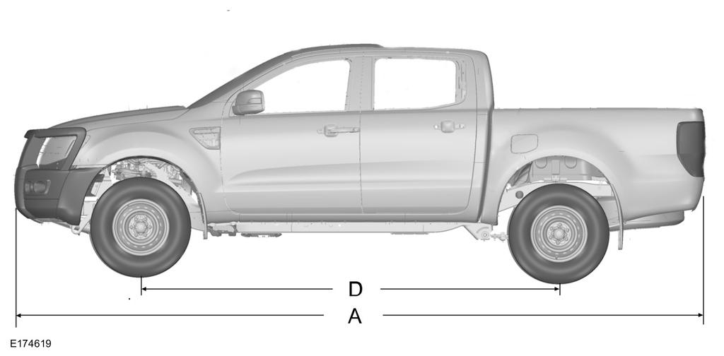
187 Capacities and Specifications Double cab 185
188 Capacities and Specifications Item A A B C C D E E Dimension Description Maximum length Maximum length - with bull bars Overall width - excluding exterior mirrors Overall height (4x2) Overall height (4x2 * or 4x4) Wheelbase Track - front and rear (4x2) Track - front and rear (4x2 * or 4x4) Dimension in mm (inches) 5359 (211.0) 5434 (214.0) 1850 (72.8) 1716 (67.5) ( ) (126.8) 1590 (62.6) 1560 (61.4) 1 Depending on tyre size * Vehicles with increased ride height 186

189 Capacities and Specifications TOWBAR DIMENSIONS 4x2 187
 Attachment point - centre of tow ball (4x2 * or 4x4) Dimension in mm (inches) 124 ± 5 (4.8 ± 0.2) 221.5 ± 5 (8.7 ± 0.")
190 Capacities and Specifications 4x2 (vehicles with increased ride height) and 4x4 Item A A Dimension Description Attachment point - centre of tow ball (4x2) Attachment point - centre of tow ball (4x2 * or 4x4) Dimension in mm (inches) 124 ± 5 (4.8 ± 0.2) ± 5 (8.7 ± 0.2) 188
191 Capacities and Specifications Item B C D D E E F F G G H H J J Dimension Description Centre of tow ball - side member Outside of side member Centre of tow ball - centre of 1st attachment point (4x2) Centre of tow ball - centre of 1st attachment point (4x2 * or 4x4) Centre of tow ball - centre of 2nd attachment point (4x2) Centre of tow ball - centre of 2nd attachment point (4x2 * or 4x4) Centre of tow ball - centre of 3rd attachment point (4x2) Centre of tow ball - centre of 3rd attachment point (4x2 * or 4x4) Center of tow ball - centre of 4th attachment point (4x2) Center of tow ball - centre of 4th attachment point (4x2 * or 4x4) Center of tow ball - centre of 5th attachment point (4x2) Center of tow ball - centre of 5th attachment point (4x2 * or 4x4) Center of tow ball - centre of 6th attachment point (4x2) Center of tow ball - centre of 6th attachment point (4x2 * or 4x4) Dimension in mm (inches) 588 (23.1) 1176 (46.3) 419 ± 5 (16.5 ± 0.2) 363 ± 5 (14.3 ± 0.2) 442 ± 5 (17.4 ± 0.2) 386 ± 5 (15.2 ± 0.2) 542 ± 5 (21.3 ± 0.2) 486 ± 5 (19.1 ± 0.2) 785 ± 5 (30.9 ± 0.2) 728 ± 5 (28.7 ± 0.2) 429 ± 5 (16.8 ± 0.2) 373 ± 5 (14.7 ± 0.2) 504 ± 5 (19.8 ± 0.2) 448 ± 5 (17.6 ± 0.2) * Vehicles with increased ride height 189


192 Capacities and Specifications VEHICLE IDENTIFICATION PLATE A B C D E Vehicle identification number Gross vehicle weight Gross train weight Maximum front axle weight Maximum rear axle weight The vehicle identification number is also stamped beneath the front door on the chassis, on the right-hand side. The vehicle identification plate with your vehicle identification number and maximum weights is located on the bottom of the lock side of the passenger door aperture. VEHICLE IDENTIFICATION NUMBER The vehicle identification number is on the left-hand side of the instrument panel. 190
193 SYNC (If Equipped) GENERAL INFORMATION SYNC is an in-vehicle communications system that works with your Bluetooth-enabled cell phone and portable media player. This allows you to: Make and receive calls Access and play music from your media player Use Emergency Assistance Access phonebook contacts and music using voice commands Stream music from your connected cell phone Select pre-defined text messages Use the advanced voice recognition system Charge your USB device (if your device supports this). Make sure that you review your device's manual before using it with SYNC. Support For further support, see an authorized dealer. For more information, visit the regional Ford website. 191
194 SYNC (If Equipped) Safety Information WARNING Driving while distracted can result in loss of vehicle control, crash and injury. We strongly recommend that you use extreme caution when using any device that may take your focus off the road. Your primary responsibility is the safe operation of your vehicle. We recommend against the use of any hand-held device while driving and encourage the use of voice-operated systems when possible. Make sure you are aware of all applicable local laws that may affect the use of electronic devices while driving. When using SYNC: Do not operate playing devices if the power cords or cables are broken, split or damaged. Carefully place cords and cables where you cannot step on them or they do not interfere with the operation of pedals, seats, compartments or safe driving abilities. Do not leave playing devices in your vehicle during extreme conditions as it could cause them damage. Refer to your device's manual for further information. Do not attempt to service or repair the system. See an authorized dealer. Privacy Information When a cell phone is connected to SYNC, the system creates a profile that is linked to that cell phone. The system creates the profile to offer you more mobile features and to operate more efficiently. Among other things, this profile may contain data about your phonebook, text messages (read and unread) and call history. This will include the history of calls when your cell phone was not connected to the system. If you connect a media player, the system creates and retains an index of supported media content. The system also records a short development log of approximately 10 minutes of all recent system activity. The log profile and other system data may be used to improve the system and help diagnose any problems that may occur. The cell phone profile, media player index and development log will remain in the system unless deleted. They are generally accessible in your vehicle only when you connect your cell phone or media player. If you no longer plan to use the system or your vehicle, we recommend you complete a master reset to erase all stored information. Special equipment is required to access system data. Access to your vehicle's SYNC module is also required. We will not access the system data for any purpose other than as described without consent. Examples where system data can be accessed are for a court order, where required by law enforcement, other government authorities or other third parties acting with lawful authority. Other parties may seek to access the information independently of us. Further privacy information is available. See SYNC Applications and Services (page 206). USING VOICE RECOGNITION This system helps you control many features using voice commands. This allows you to keep your hands on the steering wheel and focus on what is around you. Helpful Hints Make sure the interior of your vehicle is as quiet as possible. Wind noise from open windows and road vibrations may prevent the system from correctly recognizing spoken commands. 192
195 SYNC (If Equipped) Before giving a voice command, wait for the system announcement to finish followed by a single beep. Any command spoken before this does not register with the system. Speak naturally, without long pauses between words. Bluetooth audio (cancel stop exit) Command ((line AV audio video) in AUX audio video) (phone Blackberry iphone Mobile) (USB [stick] ipod MP3 [player]) voice settings [main menu] help System Interaction and Feedback The system provides feedback through audible tones, prompts, questions and spoken confirmations depending on the situation and your chosen level of interaction. You can customize the voice recognition system to provide more or less instruction and feedback. You can interrupt the system at any time while it is speaking by pressing the voice button. You can also cancel a voice session at any time by pressing and holding the voice button. Initiating a Voice Session Press the voice button. A list of available commands appears in the display. Description Stream audio from your cell phone. Cancel the requested action. Access the device connected to the auxiliary input jack. Make calls. Access the device connected to your USB port. Adjust the level of voice interaction and feedback. Hear a list of voice commands available in the current mode. The default setting is to a higher level of interaction in order to help you learn to use the system. You can change these settings at any time. Adjusting the Interaction Level Press the voice button. When prompted: Command voice settings Description Provides access to change the interaction level. Then any of the following: 193
196 SYNC (If Equipped) Command interaction mode advanced interaction mode novice Description Provides less audible interaction and more tone prompts. Provides more detailed interaction and guidance. Confirmation prompts are short questions the system asks when it is not sure of your request or when there is more than one possible response to your request. For example, the system may ask if the command phone is correct. Press the voice button. When prompted: Command voice settings Description Provides access to change the confirmation prompt setting. Then any of the following: Command confirmation prompts off confirmation prompts on Description Makes a best guess from the command. You may still occasionally be asked to confirm settings. Clarifies your voice command with a short question. The system creates suggestion lists when it has the same confidence level of several options based on your voice commands. When switched on, the system may prompt you with as many as four possibilities for clarification. Command media candidate lists off media candidate lists on phone candidate lists off phone candidate lists on Description Makes a best guess from the media suggestion list. The system may occasionally ask you questions. Clarifies your voice command for media suggestions. Makes a best guess from the cell phone suggestion list. The system may occasionally ask you questions. Clarifies your voice command for cell phone suggestions. 194
197 SYNC (If Equipped) Changing the Voice Settings You can change the voice settings using Action the information and entertainment display. Press the MENU button. Message 1 2 SYNC-Settings Voice settings USING SYNC WITH YOUR PHONE Hands-free calling is one of the main features of SYNC. While the system supports a variety of features, many are dependent on your cell phone's functionality. At a minimum, most cell phones with Bluetooth wireless technology support the following functions: Answering an incoming call. Ending a call. Using privacy mode. Dialing a number. Redialing. Call waiting notification. Caller ID. Other features such as text messaging using Bluetooth and automatic phonebook download are cell phone dependent features. To check your cell phone's compatibility, refer to your device's manual or visit the regional Ford website. Pairing a Cell Phone For the First Time Wirelessly pairing your cell phone with the system allows you to make and receive hands-free calls. Note: You must switch the ignition and radio on. Note: To scroll through the menus, press the up or down arrows on your audio system. 1. Make sure the Bluetooth feature on your cell phone is switched on before starting the search. Refer to your device's manual if necessary. 2. Press the PHONE button. When the audio display indicates that no phones are paired, select the option to add. 3. When a message to begin pairing appears in the audio display, search for SYNC on your cell phone to start the pairing process. 4. Select SYNC on your cell phone. 5. Wait until the PIN appears on the phone display. Compare the PIN on the phone with the PIN shown in the audio display and accept the request on the phone and the vehicle display. The display indicates when the pairing is successful. Note: In some cases the phone will request to enter a PIN. Enter the six-digit PIN provided by the system in the audio display. The display indicates when the pairing is successful. Depending on your cell phone's capability and your market, the system may prompt you with questions such as setting the current cell phone as the primary cell phone (the cell phone the system automatically tries to connect with first when you switch the ignition on) or downloading your phonebook. 195

198 SYNC (If Equipped) The information display may show your cell phone's battery charge level and signal strength. Pairing Subsequent Cell Phones Wirelessly pairing your cell phone with the system allows you to make and receive hands-free calls. Note: You must switch the ignition and radio on. Note: To scroll through the menus, press the up or down arrows on your audio system. 1. Make sure the Bluetooth feature on your cell phone is switched on before starting the search. Refer to your device's manual if necessary. 2. Press the PHONE button. 3. Select the option for Bluetooth devices. 4. Press the OK button. 5. Select the option to add. This starts the pairing process. 6. When a message to begin pairing appears in the audio display, search for SYNC on your device to start the pairing process. 7. Select SYNC on your cell phone. 8. Wait until the PIN appears on the phone display. Compare the PIN on the phone with the PIN shown in the audio display and accept the request on the phone and the vehicle display. The display indicates when the pairing is successful. Note: In some cases the phone will request to enter a PIN. Enter the six-digit PIN provided by the system in the audio display. The display indicates when the pairing is successful. The system may prompt you with questions such as setting the current cell phone as the primary cell phone or downloading your phonebook. Cell Phone Voice Commands Press the voice button and when prompted say either: Command Action call (someone [[a] name]) Call <name> at home Call <name> at work Call <name> in office Call <name> on cell Call <name> on other dial [[a] number] ([go to] privacy [on] transfer to phone handsfree off) You do not need to say "phone" prior to these commands. You do not need to say "phone" prior to these commands. You do not need to say "phone" prior to these commands. You do not need to say "phone" prior to these commands. You do not need to say "phone" prior to these commands. You do not need to say "phone" prior to these commands. You do not need to say "phone" prior to these commands. These commands are only available during a call. 196
199 SYNC (If Equipped) Command (hold call [on] (put place) call on hold) (hold call off take call off hold) mute [call] [on] (mute [call] off Unmute [call]) join (call calls) Action These commands are only available during a call. These commands are only available during a call. These commands are only available during a call. These commands are only available during a call. These commands are only available during a call. Phonebook Commands When you ask the system to access a phonebook name or number the requested information appears in the audio display. Command Press the voice button and when prompted say either: Action call (someone [[a] name]) dial [[a] number] To call the contact. 112 (one-one-two), 700 (seven hundred) etc. Pound Number 0 (zero) to 9 (nine) Asterisk clear (delete correct) Deletes all entered digits Deletes the last set of entered digits. Plus Star Note: To exit dial mode, press and hold the phone button or any button on the audio unit. Menu Commands Press the voice button and when prompted say either: 197
200 SYNC (If Equipped) (turn ringer on silent mode off) (turn ringer off silent mode [on]) Command Words in parentheses or brackets are optional and do not have to be spoken for the system to understand the command. Making a Call Press the voice button and when prompted say either: Command call (someone [[a] name]) dial [[a] number] Action Followed by a number. When the system confirms the number say: dial [[a] number] To erase the last spoken digit say: Command (delete correct) Action Or press the left arrow button on the audio unit. To erase all spoken digits say: clear Command Action Or press and hold the left arrow button on the audio unit. To end the call, press the end call button on the steering wheel or select the end call option in the audio display and press OK. 198
201 SYNC (If Equipped) Receiving a Call When receiving a call, you can: Answer the call by pressing the accept call button on the steering wheel or by selecting the accept call option in the audio display. Press the OK button. Reject the call by pressing the reject call button on the steering wheel or by selecting the reject call option in the audio display. Press the OK button. Ignore the call by doing nothing. Cell Phone Options During an Active Call During an active call, you have extra menu features which become available, for example putting a call on hold. To access this menu, choose one of the options available at the bottom of the audio display or select the option for more. Message Description and Action Mic. off Privacy Hold Dial a number Join calls Phonebook Turn your vehicle's microphone off. To turn the microphone on, select the option again. Switch a call from an active hands-free environment to your cell phone for a more private conversation. When selected, the audio display will indicate the call is private. Put an active call on hold. When selected, the audio display will indicate the call is on hold. Enter numbers using the audio system numeric keypad, for example numbers for passwords. Join two separate calls. The system supports a maximum of three callers on a multi-party or conference call. 1. Select the option for more. 2. Access the desired contact through the system or use voice commands to place the second call. Once actively in the second call, select the option for more. 3. Scroll to the option to join calls and press the OK button. Access your phonebook contacts. 1. Select the option for more. 2. Scroll to the option for phonebook and press the OK button. 3. Scroll through your phonebook contacts. 199
202 SYNC (If Equipped) Message Description and Action 4. Press the OK button again when the desired selection appears in the audio display. 5. Press the OK button or dial button to call the selection. Call history Access your call history log. 1. Select the option for more. 2. Scroll to the option until call history appears. Press the OK button. 3. Scroll through your call history options (incoming, outgoing or missed). 4. Press the OK button again when the desired selection appears in the audio display. 5. Press the OK button or dial button to call the selection. Accessing Features Through the Cell Phone Menu You can access your call history, phonebook, sent text messages as well as access cell phone and system settings. You can also access advanced features such as emergency assistance. The system attempts to automatically re-download your phonebook and call history each time your cell phone connects to the system. You must turn on the auto download feature if your cell phone supports it. Note: This is a cell phone dependent feature. 1. Press the PHONE button to enter the cell phone menu. 2. Select one of the options available. Message Description and Action Dial a number Redial Phonebook Dial a number using the audio system numeric keypad. Redial the last number called (if available). Press the OK button to select. Access your downloaded phonebook. 1. Press the OK button to confirm and enter. You can use the options at the bottom of the screen to quickly access an alphabetical category. You can also use the letters on the keypad to jump in the list. 2. Scroll through your phonebook contacts. 200
203 SYNC (If Equipped) Message Description and Action 3. Press the OK button again when the desired selection appears in the audio display. 4. Press the OK button or dial button to call the selection. Call history Speed Dial Text messaging BT Devices Phone settings Emergency Assistance Access any previously dialed, received or missed calls. 1. Press the OK button to select. 2. Scroll to select either incoming calls, outgoing calls or missed calls. Press the OK button to make your selection. 3. Press the OK button or dial button to call the selection. Select one of 10 speed dial entries. To set a speed dial entry, go to the phonebook and press and hold one of the numbers on the audio system numeric keypad. Send, download and delete text messages. Access the option for Bluetooth device menu listings (add, connect, set as primary, on or off, delete). View various settings and features on your cell phone. Turn the SYNC emergency assistance feature on or off. Text Messaging The system allows you to receive, send, download and delete text messages. The system can also read incoming text messages to you so that you do not have to take your eyes off the road. Note: This is a cell phone dependent feature. Receiving a Text Message When a new message arrives, an audible tone sounds and the audio display indicates you have a new message. You have these options: Select the listen option to have the system read the message to you. Select the view option to open the text message. Select the ignore option or do nothing and the message goes into your text message inbox. Once selected, you have the ability to have the message read out to you, to view other messages or to select the more option. Press the voice button and say "Read text message". Select the more option and use the arrow buttons to scroll through further options. Note: Your cell phone must support downloading text messages using Bluetooth to receive incoming text messages. Choose from the following: 201
204 SYNC (If Equipped) Message Reply to sender Call sender Forward msg. Action Press the OK button to access and then scroll through the list of pre-defined messages to send. Press the OK button to call the sender of the message. Press the OK button to forward the message to anyone in your phonebook or call history. You can also choose to enter a number. Sending, Downloading and Deleting Your Text Messages 1. Press the PHONE button. Message 2. Select the text messaging option, then press the OK button. Choose from the following: Description and Action New View Delete More... When you select the option to send a text message, a list of pre-defined messages appear in the audio display. Allows you to send a new text message based on a pre-defined set of 15 messages. Allows you to read the full message and in addition provides the option to have the message read out to you by the system. To go to the next message select the more option. This allows you to reply to the sender, call the sender or forward the message. Allows you to delete current text messages from the system (not your cell phone). The audio display indicates when all your text messages have been deleted. Allows you to delete all messages or to manually trigger a download of all unread messages from your cell phone. Sending a Text Message 1. Select the send option when the desired selection is highlighted in the audio display. 2. Select the confirmation option when the contact appears and press the OK button again to confirm when the system asks if you would like to send the message. Each text message is sent with a pre-defined signature. Note: You can send text messages either by choosing a contact from the phonebook and selecting the text option from the audio display or by replying to a received message in the inbox. Note: Only one recipient is allowed per text message. 202
205 SYNC (If Equipped) Accessing Your Cell Phone Settings These are cell phone dependent features. Your cell phone settings allow you to access and adjust features such as your ringtone, text message notification, modify your phonebook and set up automatic Message download. 1. Press the PHONE button. 2. Scroll until the phone settings option appears, then press the OK button. 3. Scroll to select from the following options: Description and Action Set as master Phone status Set ringtone Text msg notify Phonebook pref. If this option is checked, the system will use this cell phone as the master when there is more than one cell phone paired to the system. This option can be changed for all paired cell phones (not only for the active one) using the Bluetooth devices menu. See the cell phone name, provider name, cell phone number, signal level and battery level. When done, press the left arrow button to return to the cell phone status menu. Select which ringtone sounds during an incoming call (one of the system's or your cell phone's). If your cell phone supports in-band ringing, your cell phone's ringtone sounds when you choose the cell phone ringtone option. 1. Press the OK button to select and scroll to hear each ringtone. 2. Press the OK button to select. Have the option of hearing an audible tone to notify you when a text message arrives. Press the OK button to turn the audible tone on or off. Modify the contents of your phonebook, e.g. add, delete, download. Press the OK button to select and scroll between the options in the table below. To modify the phone book preferences, choose from the following: 203
206 SYNC (If Equipped) Message Add contacts Delete Download now Auto-download Description and Action Push the desired contacts on your cell phone. Refer to your device's manual on how to push contacts. Press the OK button to add more contacts from your phonebook. When a message asking you to delete appears, select the option to confirm. Press the OK button to delete the current phonebook and call history. The system takes you back to the menu for phone settings. Press the OK button to select and download your phonebook to the system. When automatic download is switched on, any changes, additions or deletions saved in the system since your last download are deleted. When automatic download is switched off, your phonebook will not be downloaded when your cell phone connects to the system. Your phonebook, call history and text messages can only be accessed when your paired cell phone is connected to the system. Check or uncheck this option to automatically download your phonebook each time your cell phone connects to the system. Downloading times are cell phone dependent and quantity dependent. Bluetooth Devices This menu provides access to your Bluetooth devices. Use the arrow buttons to scroll through the menu options. It allows you to add, connect and delete devices and set a cell phone as primary. Bluetooth Devices Menu Options 1. Press the PHONE button. 2. Scroll until the Bluetooth device option appears, then press the OK button. 3. Scroll to select from the following options: Add Message Description and Action Pair additional cell phones to the system. 1. Select the option to add to start the pairing process. 2. When a message to begin pairing appears in the audio display, search for SYNC on your cell phone. Refer to your device's manual if necessary. 3. Select SYNC on your cell phone. 204
207 SYNC (If Equipped) Message Description and Action 4. Wait until the PIN appears on the phone display. Compare the PIN on the phone with the PIN shown in the audio display and accept the request on the phones and the vehicles display. The display indicates when the pairing is successful. * 5. When the option to set the cell phone as the primary cell phone appears, select either yes or no. 6. Depending on the functionality of your cell phone, the system may ask you extra questions (for example, if you would like to download your phonebook). Select either yes or no to confirm your response. Delete Master Conn. Discon. After deleting a cell phone from the list, the cell phone can only be connected again by repeating the full pairing process. Select the delete option and confirm when the system asks to delete the selected device. The system attempts to connect with the primary cell phone every time you switch the ignition on. When a cell phone is selected as primary, it appears first in the list and is marked with an asterisk. Set a previously paired cell phone as your primary cell phone. Select the master option to confirm the primary cell phone. Connect a previously paired cell phone. You can only have one cell phone connected at a time to use the cell phone functionality. When another cell phone is connected, the previous cell phone will be disconnected from the telephone services. The system allows you to use different Bluetooth devices for the cell phone functionality and the Bluetooth audio music playback feature at the same time. Disconnects the selected cell phone. Select this option and confirm when asked to. After disconnecting a cell phone, it can be connected again without repeating the full pairing process. * In some cases the phone will request to enter a PIN. Enter the six-digit PIN provided by the system in the audio display. The display indicates when the pairing is successful. System Settings 1. Press the MENU button. 2. Select the SYNC settings option, then press the OK button. 3. Scroll to select from the following options: 205
208 SYNC (If Equipped) Message Bluetooth on Set defaults Master reset Install on SYNC System info Voice settings Browse USB Emergency Assistance Description and Action Check or uncheck this option to turn the Bluetooth interface of the system on or off. Select this option then press the OK button to change the option's status. This selection does not erase your indexed information (phonebook, call history, text messages and paired devices). Select this option and confirm when prompted in the audio display. Return to the factory default settings. Completely erase all information stored on the system (phonebook, call history, text messages and paired devices) and return to the factory default settings. Select this option and confirm when prompted in the audio display. The display indicates when complete and the system takes you back to the previous menu. Install applications or software updates you have downloaded. Select this option and confirm when prompted in the audio display. There must be a valid SYNC application or update available on the USB thumb drive in order to finish an installation successfully. Display the system's version numbers as well as its serial number. Press the OK button to select. The voice settings submenu contains various options. See Using Voice Recognition (page 192). Browse the actual menu structure of the connected USB device. Press the OK button and use the up or down arrows to scroll through the folders and files. Use the left or right arrows to enter and leave a folder. Media content can be directly selected for playback from this menu. You can turn the emergency assistance feature on or off. See SYNC Applications and Services (page 206). SYNC APPLICATIONS AND SERVICES Press the MENU button to enter the system menu. A list of available applications appears. Each application may have its own specific settings. 206
209 SYNC (If Equipped) SYNC-Apps Message Description and Action Scroll to this option, and then press OK. SYNC Emergency Assistance WARNINGS For this feature to work, your cell phone must have Bluetooth and be compatible with the system. Always place your cell phone in a secure location inside your vehicle. Failure to do so may cause serious injury to someone or damage the cell phone which could prevent this feature from working correctly. Unless the feature setting is switched on prior to a crash, the system will not attempt to place an emergency call which could delay the response time, potentially increasing the risk of serious injury or death. Do not wait for the system to make an emergency call if you can do it yourself. Dial emergency services immediately to avoid a delayed response time. If you do not hear Emergency Assistance within five seconds of the crash, the system or cell phone may be damaged or non-functional. If a crash deploys an airbag or triggers the fuel pump shut off, the system may contact emergency services by dialing 112 (the wireless emergency number that works in most European countries) through a paired and connected cell phone. For more information about the system and Emergency Assistance, visit the regional Ford website. Note: Before selecting this feature, you must read the Emergency Assistance privacy notice later in this section for important information. Note: When you switch this feature on or off, that setting applies for all paired cell phones. If you have turned this feature off and a previously paired phone connects when you switch on the ignition, either a voice message plays, a display message or icon is shown, or both. Note: Every cell phone operates differently. While this feature works with most cell phones, some cell phones may experience difficulties using this feature. Note: Make sure you are familiar with the information about airbag deployment. See Supplementary Restraints System (page 27). Switching Emergency Assistance On and Off Press the MENU button then select: SYNC-Apps Message Emergency Assistance Press OK. Action Press OK. Select the option you require and press OK. 207
210 SYNC (If Equipped) Display Options If you switch on this feature, a confirmation message appears in the display. If you switch off this feature, a dialog will appear in the display, which allows you to set a voice reminder. Off with voice reminder provides a display and voice reminder when your cell phone connects and your vehicle starts. Off without voice reminder provides a display reminder only without a voice reminder when your cell phone connects. To make sure that Emergency Assistance works correctly: The system must have power and be working correctly at the time of the crash and during feature activation and use. You must switch on the feature before a crash. You must have a cell phone connected to the system. In certain countries, it may be necessary to have a valid and registered SIM card with credit in order to place and maintain an emergency call. A connected cell phone must have the ability to make and maintain an outgoing call at the time of the crash. A connected cell phone must have adequate network coverage, battery power and signal strength. Your vehicle must have battery power. Note: This feature only works in a European country or region where SYNC Emergency Assistance can call the local emergency services. Visit the regional Ford website for details. In the Event of a Crash Note: Not every crash deploys an airbag or triggers the fuel pump shut off (which may turn on Emergency Assistance). However, if Emergency Assistance is triggered the system tries to contact the emergency services. If a connected cell phone sustains damage or loses connection to the system, it searches for and tries to connect to any available previously paired cell phone. The system attempts to dial 112. Before making a call: If you do not cancel the call and SYNC makes a successful call, an introductory message plays for the emergency operator. After this message, there is hands-free communication between your vehicle's occupants and the operator. The system provides a short window of time (approximately 10 seconds) to cancel the call. If you do not cancel the call, the system attempts to dial 112. The system plays a message letting you know when it attempts to make an emergency call. You can cancel the call by selecting the relevant function button or by pressing the end call button on the steering wheel. During a call: Emergency Assistance uses your vehicle GPS or cellular network information when available to determine the most appropriate language to use. It alerts the emergency operator of the crash and delivers the introductory message. This may include your vehicle GPS coordinates. The language the system uses to interact with the occupants of your vehicle may differ from the language used to deliver information to the emergency operator. 208
211 SYNC (If Equipped) After the delivery of the introductory message the voice line opens so that you can speak hands-free with the emergency operator. When the line is connected, you must be prepared to provide your name, phone number and location information immediately. Note: While the system provides information to the emergency operator, the system plays a message letting you know it is sending important information. It then lets you know when the line is open to start hands-free communication. Note: During an Emergency Assistance call, an emergency priority screen appears which contains vehicle GPS coordinates when available. Note: It is possible that GPS location information is not available at the time of the crash; in this case, Emergency Assistance will still attempt to place an emergency call. Note: It is possible that the emergency services will not receive the GPS coordinates; in this case, hands-free communication with an emergency operator is available. Note: The emergency operator may also receive information from the cellular network such as cell phone number, cell phone location and cell phone carrier name independent from SYNC Emergency Assistance. Emergency Assistance may not work if: Your cell phone or Emergency Assistance hardware sustains damage in the crash. The vehicle battery or the system has no power. A crash ejects your cell phone from your vehicle. You do not have a valid and registered SIM card with credit in your cell phone. You are in a European country or region where the SYNC Emergency Assistance cannot place the call. Visit the regional Ford website for details. Important Information about the Emergency Assistance Feature Emergency Assistance does not currently call emergency services in the following markets: Albania, Belarus, Bosnia and Herzegovina, Macedonia, Netherlands, Ukraine, Moldova and Russia. Visit the regional Ford website for the latest details. Emergency Assistance Privacy Notice When you switch on Emergency Assistance, it may disclose to emergency services that your vehicle has been in a crash involving the deployment of an airbag or activation of the fuel pump shut off. This feature has the capability to disclose your location information to the emergency operator or other details about your vehicle or crash to provide the most appropriate emergency services. If you do not want to disclose this information, do not switch on the feature. SYNC AppLink The system enables voice and manual control of SYNC AppLink enabled smartphone apps. Once an app is running through AppLink, you can control main features of the app through voice commands and manual controls. Note: You must pair and connect your smartphone to SYNC to access AppLink. Note: iphone users need to connect the phone to the USB port. Note: Android users need to connect the phone to SYNC using Bluetooth. 209
212 SYNC (If Equipped) Note: For information on available apps, supported smartphone devices and troubleshooting tips please visit the Ford website. Note: Make sure you have an active account for the app that you have downloaded. Some apps will work automatically with no setup. Other apps will want you to configure your personal settings and personalize your experience by creating stations or favorites. We recommend you do this at home or outside of your vehicle. Message To Access Using the SYNC Menu Scroll through the list of available applications and press OK to select an app. Once an app is running through SYNC, press the right arrow button to access the app menu. You can access various app features from here, for example thumbs up and thumbs down. Press the left arrow button to exit the app menu. Press the MENU button then select: Description and Action SYNC-Apps Mobile Apps Scroll to this option, and then press OK. Find new Apps Select this option if the app required is not listed. Note: If a SYNC AppLink compatible app cannot be found, make sure the required app is running on the mobile device. To Access Using Voice Commands Press the voice button and when prompted say: Command mobile (apps applications) Description and Action Say the name of the application after the tone. The application will start. While an app is running through SYNC, you can press the voice button and speak commands specific to the app. The following voice commands are always available: Command [main menu] help mobile (apps applications) list [mobile] (apps applications) Description and Action Use this command to hear a list of available voice commands. The system will prompt you to say the name of the app to start it. The system will list all of the currently available mobile apps. 210
213 SYNC (If Equipped) Command find [new] [mobile] (apps applications) <the name of the app> <the name of the app> Help (quit exit close) Description and Action The system will search your connected mobile device for SYNC compatible apps. Say the name of an app to start it on SYNC. The system will list the available voice commands for the requested app. Use this command followed by the name of the app. Enabling and Disabling Push Notifications Some apps can send push notifications. A push notification is an alert from an app running in the background and is delivered by voice, pop up or both. This may be particularly useful for news or location based apps. Press the MENU button then select: Message SYNC-Apps Mobile Apps Settings All Apps Description and Action If push notifications are supported, this setting will be listed. Select to enable or disable the feature as required. Enabling SYNC Mobile Apps To use the system you must consent to send and receive app authorization information and updates, using the data plan associated with the connected device. Data is sent to Ford in the United States through the connected device. The information is encrypted and includes your VIN, SYNC module number, anonymous usage statistics and debugging information. Updates may take place automatically. Note: You must enable mobile apps for each connected device the first time you select a mobile app using the system. Note: Standard data rates will apply. Ford is not responsible for any additional charges you may receive from your service provider, when your vehicle sends or receives data through the connected device. This includes any additional charges incurred due to driving in areas when roaming out of a home network. 211
214 SYNC (If Equipped) App Status You can view the current status of an app in the settings menu. There are three possible statuses: Message Update needed Up-to-date Updating... Description and Action The system has detected a new app requiring authorization or a general permissions update is required. No update is required. The system is trying to receive an update. Options in the settings menu: Message Request Update Disable Updates Description and Action If an update is required and you want to manually request the update, for example when you are in a Wi-Fi hotspot. Select this option to disable automatic updates. App Permissions Permissions are divided by groups. You can grant these group permissions individually. You can change a permission group status any time when not driving, by using the settings menu. When you launch an app using SYNC, the system may ask you to grant certain permissions, for example: To allow your vehicle to provide vehicle information to the app including, but not limited to: Fuel level, fuel consumption, engine speed, battery voltage, odometer, VIN, external temperature, gear position, tire pressure, ambient temperature, date and time. To allow your vehicle to provide driving characteristic information, including, but not limited to: MyKey, seat belt status, engine speeds, braking events, brake pedal switch, acceleration, accelerator pedal position, clutch pedal switch, trip length, trip time, trip cost, percent engine on time, and percent of time at speed. 212
215 SYNC (If Equipped) To allow your vehicle to provide location information, including: GPS and speed. To allow the app to send push notifications using the vehicle display and voice capabilities while running in a background state. Note: You will only need to grant permissions the first time you use an app with SYNC. Note: We are not responsible or liable for any damages or loss of privacy relating to usage of an app, or dissemination of any vehicle data that you approve us to provide to an app. USING SYNC WITH YOUR MEDIA PLAYER You can access and play music from your media player through your vehicle's speaker system using the system's media menu or voice commands. You can also sort and play your music by specific categories, for example artist or albums. SYNC is capable of hosting nearly any media player including: ipod, Zune, Plays from device players, and most USB drives. SYNC also supports audio formats, for example MP3, WMA, WAV and ACC. Confirm that the USB device has been formatted correctly and has the following specifications: USB 2.0. File format must be FAT16/32. Supply current not greater than 500mA. Note: NTFS file format is not supported. The format of the audio files on the USB device must be: MP3. Non DRM protected WMA. WAV. AAC. Connecting Your Media Player to the USB Port Note: If your media player has a power switch, make sure you switch on the device. To Connect Using Voice Commands 1. Plug the device into your vehicle's USB port. 2. Press the voice button and when prompted say: Voice Command Description and Action (USB [stick] ipod MP3 [player]) You can now play music by saying any of the appropriate voice commands. Refer to the media voice commands. You do not need to say words that appear within square brackets. For example, for where (USB [stick] ipod MP3 [player]) appears, you can say USB or USB stick. To Connect Using the System Menu 1. Plug the device into your vehicle's USB port. 2. Press the AUX button until an initializing message appears in the display. 213
216 SYNC (If Equipped) Message Browse USB Description and Action Depending on how many media files are on your connected device, an indexing message may appear in the display. When indexing is complete, the screen returns to the playback menu. Choose from the following: Message Play all Playlists Songs Artists Albums Genres Browse USB Reset USB Exit What's Playing? At any time during playback, you can press the voice button and ask the system what is playing. The system reads the metadata tags of the current track, if populated. Media Voice Commands Press the voice button and when prompted say: Voice Command (USB [stick] ipod MP3 [player]) Description and Action You can now play music by saying any of the appropriate voice commands. You can say any of the voice commands that appear within open and close brackets that are separated by. For example, where; (what's what is) appears you say; what's or what is. You must say any of the voice commands that appear outside of open and close brackets. For example, where; who plays this (what's what is) playing, you must say; who plays this (what's or what is) playing. 214
217 SYNC (If Equipped) Then any of the following: Voice Command play pause play [album] [by [artist]] Play all play [artist] play [genre] [play] next track play [playlist] [play] previous track play [song track title file] repeat off repeat one [on] (browse search show) album (browse search show) artist (browse search show) genre Voice Command Guide * * * * * Voice Command (browse search show) playlist (browse search show) all (album albums) (browse search show) all (artist artists) (browse search show) all (genre genres) (browse search show) all (playlist playlists) (browse search show) all (song songs title titles file files track tracks) shuffle [all] [on] shuffle off [play] (similar music more like this) ((who's who is) this who plays this (what's what is) playing [now] (what which) (song track artist) is this (who's who is) playing (what's what is) this) * This voice command is not available until indexing is complete. Voice Command (browse search show) genre [play] (similar music more like this) (browse search show) artist (browse search show) album Description and Action The system searches all the data from your indexed music and if available, begins to play the chosen type of music. The system compiles a playlist and then plays similar music to what is currently playing from the USB port using indexed metadata information. The system searches for a specific artist, track or album from the music indexed through the USB port. The system searches for a specific artist, track or album from the music indexed through the USB port. 215
218 SYNC (If Equipped) The system is also capable of playing music from your cell phone through Bluetooth. To switch the Bluetooth audio on, use the AUX or Source button or press the voice button and when prompted and say: Voice Command Bluetooth audio Description and Action Then any of the following: pause play Voice Command [play] next track [play] previous track Media Menu Features The media menu allows you to select how to play your music, for example by artist, genre, shuffle or repeat, and to find similar music or reset the index of your USB devices. Description and Action Press AUX to select USB playback. Options Message Description and Action This will enter the media menu. Then any of the following: 216
219 SYNC (If Equipped) Message Shuffle Repeat track Similar music Reset SYNC USB Description and Action Choose to shuffle or repeat your music. Once you make your choice, it remains on until you switch it off. Choose to shuffle or repeat your music. Once you make your choice, it remains on until you switch it off. You can play similar types of music to the current playlist from the USB port. The system uses the metadata information of each track to compile a playlist. The system then creates a new list of similar tracks and then begins playing. Each track must have the metadata tags populated for this feature. With certain playing devices, if your metadata tags are not populated, the tracks will not be available in voice recognition, the play menu or this option. However, if you place these tracks onto your playing device in mass storage device mode they are available in voice recognition, the play menu or this option. The system places unknowns into any unpopulated metadata tag. Resets the USB index. After the new indexing is complete you can choose what to play from the USB song library. Accessing Your USB Song Library 1. Plug the device into your vehicle's USB port. 2. Press AUX to select USB playback. Message Browse USB Description and Action This menu allows you to select and play your media files by artist, album, genre, playlist and track or even to browse what is on your USB device. If there are no media files to access, the display indicates there is no media. If there are media files, you have the following options to scroll through and select: 217
220 SYNC (If Equipped) Message Description and Action Play all Playlists Songs Artists Albums Genres Play all indexed media files from your playing device one at a time in numerical order. * 1. Press OK to select. The first track title appears in the display. Access your playlists from formats, ASX, M3U, WPL or MTP. * 1. Press OK to select. 2. Scroll to select the desired playlist, and then press OK. Search for and play a specific indexed track. * 1. Press OK to select. 2. Scroll to select the desired track, and then press OK. Sort all indexed media files by artist. Once selected, the system lists and then plays all artists and tracks alphabetically. * 1. Press OK to select. 2. Scroll to select the desired artist, and then press OK. Sort all indexed media files by albums. * 1. Press OK to select. 2. Scroll to select the desired albums, and then press OK. Sort indexed music by genre type. * 1. Press OK to select. 2. Scroll to select the desired genre, and then press OK. 218
221 SYNC (If Equipped) Message Browse USB Reset USB Description and Action Browse all supported media files on your media player connected to the USB port. You can only view media files that are compatible with SYNC; other saved files are not visible. 1. Press OK to select. 2. Scroll to browse indexed media files on your flash drive, and then press OK. Resets the USB index. After the new indexing is complete, you can choose what to play from the USB song library. * You can use the buttons at the bottom of the audio display to jump to a certain alphabetical category quickly. You can also use the letters on the numeric keypad to jump in the list. Bluetooth Devices and System Settings You can access these menus using the audio display. See Using SYNC With Your Phone (page 195). SYNC TROUBLESHOOTING Your SYNC system is easy to use. However, should questions arise, please refer to the tables below. To check your cell phone's compatibility, visit the regional Ford website. Cell phone issues Issue A lot of background noise during a phone call. During a call, I can hear the other person but they cannot hear me. SYNC is not able to download my phonebook. Possible cause The audio control settings on your cell phone may be affecting SYNC performance. Possible cell phone malfunction. This is a cell phonedependent feature. Possible cell phone malfunction. Possible solution Refer to your device's manual about audio adjustments. Try switching off your cell phone, resetting it or removing the battery, then trying again. Make sure that the microphone for SYNC is not set to off. Check your cell phone's compatibility. Try switching off your cell phone, resetting it or removing the battery, then trying again. 219
222 SYNC (If Equipped) Issue The system says "Phonebook downloaded" but my SYNC phonebook is empty or is missing contacts. I am having trouble connecting my cell phone to SYNC. Text messaging is not working on SYNC. Possible cause Limitations on your cell phone's capability. This is a cell phonedependent feature. Possible cell phone malfunction. This is a cell phonedependent feature. Possible cell phone malfunction. Cell phone issues Possible solution Try pushing your phonebook contacts to SYNC by selecting the option to add. You must switch on your cell phone and the automatic phonebook download feature on SYNC. Try pushing your phonebook contacts to SYNC by selecting the option to add. If the missing contacts are stored on your SIM card, try moving them to your cell phone's memory. Remove any pictures or special ring tones associated with the missing contact. You must switch on your cell phone and the automatic phonebook download feature on SYNC. Check your cell phone's compatibility. Try switching off your cell phone, resetting it or removing the battery, then trying again. Try deleting your device from SYNC and deleting SYNC from your device, then trying again. Always check the security and auto accept prompt settings relative to the SYNC Bluetooth connection on your cell phone. Update your cell phone's firmware. Switch off the auto download setting. Check your cell phone's compatibility. Try switching off your cell phone, resetting it or removing the battery, then trying again. iphone Go to your cell phone's Settings. Go to the Bluetooth Menu. 220
223 SYNC (If Equipped) Cell phone issues Issue Possible cause Possible solution Make sure the connection status shows Not Connected. Press the blue circle to enter the next menu. Turn on Show Notifications. Turn on Sync Contacts. Your iphone is now set up to forward incoming text messages to SYNC. Repeat these steps for every other Sync vehicle you are connected to. Your iphone will only forward incoming text messages to SYNC if it is unlocked. Replying to text messages using SYNC is not supported by iphone. Text messages from WhatsApp and Facebook Messenger are not supported. Audible text messages do not work on my cell phone. This is a cell phonedependent feature. This is a cell phone limitation. Your cell phone must support downloading text messages through Bluetooth to receive incoming text messages. Access the text messaging menu of SYNC to see if your cell phone supports the feature. Press the PHONE button and then scroll and select the option for text messaging, then press OK. Because each cell phone is different, refer to your device's manual for the specific cell phone you are pairing. In fact, there can be differences between cell phones due to brand, model, service provider and software version. 221
224 SYNC (If Equipped) Issue I am having trouble connecting my device. SYNC does not recognize my device when I start my vehicle. Bluetooth audio does not stream. SYNC does not recognize music that is on my device. When I connect my iphone or ipod Touch through the USB and Bluetooth Audio at the same time, I sometimes do not hear any sound. Possible cause Possible device malfunction. This is a device limitation. This is a devicedependent feature. The device is not connected. Your music files may not contain the correct artist, song title, album or genre information. The file may be corrupted. The song may have copyright protection that does not allow it to play. This is a device limitation. USB and media issues Possible solution Try switching off the device, resetting it or removing the battery, then trying again. Make sure you are using the manufacturer's cable. Make sure correctly insert the USB cable to the device and your vehicle's USB port. Make sure that the device does not have an auto-install program or active security settings. Make sure you are not leaving the device in your vehicle during very hot or cold temperatures. Make sure you connect the device to SYNC and press play on your device. Make sure that all song details are populated. Try replacing the corrupt file with a new version. Some devices require you to change the USB settings from mass storage to media transfer protocol class. From the iphone or ipod Touch music now playing screen, select the audio device airplay icon at the very bottom of your iphone or ipod Touch screen. To listen to the iphone or ipod Touch through Bluetooth Audio, select SYNC. To listen to the iphone or ipod Touch through USB, select Dock Connector. 222
225 SYNC (If Equipped) Issue SYNC does not understand what I am saying. SYNC does not understand the name of a song or artist. SYNC does not understand or is calling the wrong contact when I want to make a call. Possible cause You may be using the wrong voice commands. You may be speaking too soon or at the wrong time. You may be using the wrong voice commands. You may not be saying the name exactly as the system saved it. The system may not be reading the name the same way you are saying it. You may be using the wrong voice commands. Voice command issues Possible solution Review the cell phone voice commands and the media voice commands at the beginning of their respective sections. Refer to the audio display during an active voice session to find a list of voice commands there. The microphone for the system is either in your rear view mirror or in the headliner just above the windshield. Review the media voice commands at the beginning of the media section. Say the song or artist exactly as the system saved it. If you say, "Play Artist Prince", the system does not play music by Prince and the Revolution or Prince and the New Power Generation. Make sure you are saying the complete title such as "California remix featuring Jennifer Nettles". If the song titles are in capital letters, you have to spell them. LOLA requires you to say "L-O-L-A". Do not use special characters in the title, as the system does not recognize them. Review the cell phone voice commands at the beginning of the cell phone section. You can also use the cell phone and media suggestion lists to get a list of possible suggestions when the system cannot fully understand you. See Using Voice Recognition (page 192). 223
226 SYNC (If Equipped) Voice command issues Issue The SYNC voice control system is having trouble recognizing foreign names stored on my cell phone. The SYNC voice control system is having trouble recognizing foreign tracks, artists, albums, genres and playlist names from my media player or USB flash drive. Possible cause You may not be saying the name exactly as the system saved it. Contacts in your phonebook may be very short and similar or they may contain special characters. Your phonebook contacts may be in capital letters. You may be saying the foreign names using the currently selected language for SYNC. You may be saying the foreign names using the currently selected language for SYNC. Possible solution Make sure you are saying the name exactly as the system saved it. For example, if the contact name is Joe Wilson, say "Call Joe Wilson". The system works better if you list full names such as "Joe Wilson" rather than "Joe". Do not use special characters such as 123 or ICE as the system does not recognize them. If the contacts are in capital letters, you have to spell them. JAKE requires you to say "Call J-A-K-E". SYNC applies the phonetic pronunciation rules of the selected language to the contact names stored on your cell phone. Helpful Hint: You can select your contact manually. Press PHONE. Select the option for phonebook and then contact name. Press the soft-key option to hear it. SYNC will read the contact name to you, giving you some idea of the pronunciation it is expecting. SYNC applies the phonetic pronunciation rules of the selected language to the names stored on your media player or USB flash drive. It is able to make some exceptions for very popular artist names (for example, U2) such that you can always use the English pronunciation for these artists. 224
227 SYNC (If Equipped) Voice command issues Issue The system generates voice prompts and the pronunciation of some words may not be accurate for my language. My previous Bluetooth voice control system allowed me to control the radio, CD, and climate control systems. Why can I not control these systems with SYNC? Possible cause SYNC uses text-tospeech voice prompt technology. The focus of SYNC is to control your mobile devices and the content stored on them. Possible solution SYNC uses a synthetically generated voice rather than pre-recorded human voice. SYNC offers several new voice control features for a wide range of languages. Dialing a contact name directly from the phonebook without pre-recording (for example, call John Smith ) or selecting a track, artist, album, genre or playlist directly from your media player (for example," play artist Madonna). SYNC offers significant capability beyond the previous system such as dialing a contact name directly from the phonebook without pre-recording (for example, call John Smith ) or selecting a track, artist, album, genre or playlist directly from your media player (for example, " play artist Madonna). 225
228 SYNC (If Equipped) Issue The language selected for the instrument cluster and information and entertainment display does not match the SYNC language (phone, USB, Bluetooth audio, voice control and voice prompts). Possible cause SYNC does not support the currently selected language for the instrument cluster and information and entertainment display. General Possible solution SYNC only supports four languages in a single module for text display, voice control and voice prompts. The country where you bought your vehicle dictates the four languages based on the most popular languages spoken. If the selected language is not available, SYNC remains in the current active language. SYNC offers several new voice control features for a wide range of languages. Dialing a contact name directly from the phonebook without pre-recording (for example, call John Smith ) or selecting a track, artist, album, genre or playlist directly from your media player (for example, play artist Madonna). 226
229 SYNC (If Equipped) Issue AppLink Mobile Applications: When I select "Find New Apps," SYNC does not find any applications. My phone is connected, but I still cannot find any apps. My phone is connected, my app(s) are running, but I still cannot find any apps. Possible cause(s) An AppLink capable phone is not connected to SYNC. AppLink-enabled apps are not installed and running on your mobile device. Sometime apps do not properly close and reopen their connection to SYNC, over ignition cycles, for example. AppLink issues Possible solution(s) Ensure you have a compatible smartphone; an Android with OS 2.3 or higher or an iphone 3GS or newer with ios 5.0 or higher. Additionally, ensure your phone is paired and connected to SYNC in order to find AppLink-capable apps on your device. iphone users must also connect to SYNC's USB port with an Apple USB cable. Ensure you have downloaded and installed the latest version of the app from your phone's app store. Ensure the app is running on your phone. Some apps require you to register or login on the app on the phone before using them with AppLink. Also, some may have a "Ford SYNC" setting, so check the app's settings menu on the phone. Closing and restarting apps may help SYNC find the application if you cannot discover it inside the vehicle. On an Android device, if apps have an "Exit' or 'Quit' option, select that then restart the app. If the app does not have that option, you can also manually "Force Close" the app by going to the phone's settings menu, selecting 'Apps.' then finding the particular app and choosing 'Force stop.' Don't forget to restart the app afterwards, then select "Find New Apps" on SYNC. On an iphone with ios7+, to force close an app, double tab the home button then swipe up on the app to close it. Tab the home button again, then select the app again to restart it. After a few seconds, the app should then appear in SYNC's Mobile App's Menu. 227
230 SYNC (If Equipped) Issue My Android phone is connected, my app(s) are running, I restarted them, but I still cannot find any apps. My iphone phone is connected, my app is running, I restarted the app but I still cannot find it on SYNC. I have an Android phone. I found and started my media app on SYNC, but there is no sound or the sound is very low. I can only see some of the AppLink apps running on my phone listed in SYNC's Mobile Apps Menu. Possible cause(s) There is a bluetooth bug on some order versions of the Android OS that may cause apps that were found on your previous vehicle drive to not be found again if you have not turned off bluetooth. The USB connection to SYNC may need to be reset. The bluetooth volume on the phone may be low. Some Android devices have a limited number of bluetooth ports apps can use to connect. If you have more AppLink apps on your phone than the number of availble Bluetooth ports, you will not see all of your apps listed in SYNC's mobile apps menu. AppLink issues Possible solution(s) Reset the Bluetooth on your phone by turning it off and then turning Bluetooth back on. If you are in your vehicle, SYNC should be able to automatically re-connect to your phone if you press the "Phone" button. Unplug the USB cable from the phone, wait a moment, and plug the USB cable back in to the phone. After a few seconds, the app should appear in SYNC's Mobile Apps Menu. If not, "Force Close" the application and restart it. Try increasing the Bluetooth volume of the device by using the device's volume control buttons which are most often found on the side of the device. Force close or uninstall the apps you do not want SYNC to find. If the app has a "Ford SYNC" setting, disable that setting in the app's settings menu on the phone. 228
231 Navigation introduction GENERAL INFORMATION Press the relevant button on the unit bezel to access the system functions. This will take you into the selected mode. One hour mode To conserve battery power, the system can be operated in one hour mode. If the ignition is off, press the ON/OFF button to switch the system on. The system will automatically switch off after one hour. System notes WARNINGS The indicated maximum speed may not be applicable to your vehicle. It is always your responsibility to control the vehicle, supervise any system and obey the correct speed limit. The front glass on the liquid crystal display may break if hit with a hard object. If the glass breaks, do not touch the liquid crystalline material. In case of contact with the skin, wash immediately with soap and water. The unit is a highgrade laser product which uses an invisible laser beam. If this is handled incorrectly it can emit dangerous rays. Do not attempt to look through any openings in the unit. CAUTIONS Irregular shaped CDs and CDs with a scratch protection film or self adhesive labels attached should not be used. Warranty claims, where this type of disc is found to be inside an audio unit returned for repair, will not be accepted. Do not clean the unit with solvents or aerosol cleaning agents. Use only a damp cloth. CAUTIONS Do not insert foreign objects into any of the unit disc drives or media card slots. Do not insert more than one disc into the unit disc drive. Use only 12 cm (4.7 inches) discs or 8 cm (3.1 inches) discs with a suitable adaptor. Do not attempt to open the unit. If the unit malfunctions consult your dealer. Improper use of settings and connections, other than those explained in this manual, can damage the unit. Do not turn the ignition key or attempt to start the engine while the software is updating. The system is recommended for use when the ignition key is turned to the accessory position or when the engine is running. If the system is used extensively when the engine is not running, care needs to be taken to avoid draining the battery. ROAD SAFETY WARNINGS The system provides you with information designed to help you reach your destination quickly and safely. For reasons of safety, the driver should only program the system when the vehicle is stationary. The system provides no assistance with respect to stop signs, traffic lights, areas under construction or other important safety information. 229
232 Navigation introduction WARNINGS Do not use the system until you have familiarized yourself with its operation. Only view the system display when driving conditions permit. Safety information Read and follow all stated safety precautions. Failure to do so may increase your risk of collision and personal injury. Ford Motor Company shall not be liable for any damages of any type arising from failure to follow these guidelines. If detailed viewing of route instructions is necessary, pull off the road when it is safe to do so and park your vehicle. Do not use the navigation system to locate emergency services. To use the system as effectively and safely as possible, always use the latest navigation information. Your dealer will be able to assist with this. 230
233 Navigation Quick start Vehicles with SD navigation system The system has a large range of features, yet is easy and intuitive to use. Route guidance is shown on the display screen. The screen provides full information for operating the system through the use of menus, text screens and map displays. Screen selections are made by scrolling through the menus using the up, down, left and right arrow buttons and pressing the OK button to activate the desired setting. Basic operation 1. Press either the NAV or MENU button to enter the menu structure. 2. Use the up, down, left and right arrow buttons and scroll through the various selection lists. 3. Press the OK button to activate your selection. Selection lists Various screens are presented which offer a selection list of available options. 1. Select the option you require, or if it is not shown on the screen use the up and down arrow buttons to view the remainder of the selection list. 2. Press the OK button to confirm your selection. Alphanumeric keypad entry When it is necessary to enter an address, a keypad will appear prompting you to enter a postcode, city, or street. 1. Use the up, down, left and right arrow buttons to select the letter or number that you require. Note: As you spell the entry the results will appear in the display. Note: The system will limit your entries to only those characters which spell a valid entry. 2. Press the OK button to activate your selection. Route setting example Navigation main screen To select the navigation system, press the NAV button. The road safety caution will be displayed. To use the system, read the caution and press the OK button. Destination input screen Use the up and down arrow buttons and scroll to Destination input. Press the OK button to activate your selection. Note: A list with several options is shown. Starting from the top, select the country followed by either the postcode if available or city and street name. Use the alphanumeric keypad and selection lists to select your address details. Once sufficient information has been entered, scroll to Start guidance and press the OK button to activate your selection. Note: If you only need to navigate to a city center for example, full address details are not required. The route is now calculated and the screen returns to the main navigation screen with instructions on how to proceed. Follow the screen information and voice prompts to reach your destination. 231
234 Navigation unit overview A Descriptions for function buttons 1-4 Function buttons 1 to 4 are context dependent, and change according to the current unit mode. Descriptions for the functions are shown at the bottom of the screen display. 232
235 Navigation unit overview Vehicles with SD navigation system A B C D E F G H Function 1. Function 2. Seek down. CD track selection. See Station tuning control (page 254). On/off and volume control. Seek up. CD track selection. See Station tuning control (page 254). Function 3. Function 4. OK. I J K L M N O Telephone keypad, station presets and navigation keypad. See Station preset buttons (page 255). See Navigation Quick start (page 231). Clock. Traffic announcement. See Traffic information control (page 256). Navigation arrows. Map. Information. Door lock indicator. 233
. See Auxiliary input jack (page 264). Radio and waveband select. See Audio unit operation (page 254). CD eject. See Compact Disc Player (page 259). CD select.")
236 Navigation unit overview P Q R S T U V W X Hazard warning flasher switch. Door lock button. See Locking and Unlocking (page 36). Navigation. Menu select. Phone menu. Auxiliary, USB and ipod select. See Auxiliary Power Points (page 79). See Auxiliary input jack (page 264). Radio and waveband select. See Audio unit operation (page 254). CD eject. See Compact Disc Player (page 259). CD select. See Compact Disc Player (page 259). 3. Use the up and down arrow buttons to select the required feature. 4. Press the OK button to confirm your selection. For map updates and system upgrades please refer to your dealer. LOADING THE NAVIGATION DATA Loading the navigation data 1. Load the navigation SD card into the aperture. 2. Press the NAV button. The road safety warning will be shown in the display. 234
237 System settings Most of the important settings for your navigation unit can be accessed via the MENU or NAV button. The following section describes the various options and how to use them. For menu structures: See Information Displays (page 59). Menu structure - Information and entertainment display - Vehicles with navigation system Route This feature allows you to customize the route to your specific journey requirements (for example continue route guidance, block specific sections of your route or select specific sections of a route). Destination input This feature allows you to enter your destination details (for example enter city names, enter street names or pick a place from a map). Traffic This feature allows you to customize how you receive traffic information (for example review and sort traffic messages, review your route or block parts of your route). Home address This feature allows you to start the route guidance to your home address or change the details of your home address. Last destinations This feature allows quick access to a history of previous destinations entered in the system. A detailed display will show the complete stored information including an overview map. Select the required repeat destination from the list. Favourites This feature allows you to customize a personal destination address book and assign user defined names to addresses and locations. A detailed display will show the complete stored information including an overview map. Select the required repeat destination from the list. Points of interest This feature allows you to customize the route to your specific journey requirements (for example select a museum on route or a specific point of interest near your destination). Tour planning This feature allows you to enter a number of different destinations and select the order in which you wish to visit them. You can also modify an existing tour or recall a previous tour. The system will automatically calculate and display your chosen journey. Store position This feature allows you to store and name your current position. Route options This feature allows you to customize the route to your specific journey requirements (for example select the fastest or most economical route or select a route that will avoid tunnels, seasonal roads and toll roads). Special functions This feature allows you to select GPS and system information or a demonstration of the system functionality. 235
238 System settings Map display This feature allows you to change the way the map screen is displayed (for example clean 2D and clean 3D view) and to customize display information for your journey (for example time to arrival and lane guidance). Assistance options This feature allows you to customize display information for your journey (for example signs, lanes and speed limits). Personal data This feature allows you to edit and delete personal data (for example your home address). Reset all settings This feature allows you to reset the navigation settings. Menu structure - Information and entertainment display - All vehicles Audio settings Adaptive volume This feature allows you to adjust the volume level to compensate for engine and road speed noise. You can turn this on and off. See Automatic volume control (page 257). Sound This feature allows you to adjust the sound settings (for example bass and treble. Nav audio mixing This feature allows you to adjust the volume mix between the navigation voice output and audio source. DSP settings This feature allows you to customize speaker output relevant to seat positions. See Digital signal processing (DSP) (page 257). DSP equaliser This feature allows you to select the music category that most suits your listening preference. The audio output will change to enhance the particular style of music chosen. See Digital signal processing (DSP) (page 257). News This feature allows you to receive news bulletins from stations on the FM waveband or radio data system (RDS) and enhanced other network (EON) linked stations, in the same way as traffic information is provided. You can turn this on and off. See News broadcasts (page 257). Alternative frequencies This feature will search for and switch to the strongest station signal when moving from one transmission area to another. See Alternative frequencies (page 257). RDS regional This feature controls the behaviour of AF switching between regionally related networks of a parent broadcaster. See Regional mode (REG) (page 258). Bluetooth This feature allows you to switch Bluetooth on or off. Clock settings Set time This feature allows you to manually adjust the time. 236
239 System settings Set date This feature allows you to manually adjust the date, month and year. GPS time This feature allows you to, if in a suitable coverage area, automatically adjust the date and time using GPS. Set time zone This feature allows you select a specific time zone. Summertime This feature allows you set the system to adjust for seasonal time differences. Note: GPS time must be selected. 24-hour mode This feature allows you to adjust the system between 12 and 24-hour mode. 237
240 Navigation system ROUTE OPTIONS MENU You can set a number of options which alter the way a route is planned. Using the up, down, left and right arrow buttons, you can select from the list which road features are to be avoided or included in the route by turning the feature on or off. Route Eco This option will prioritize the most economical route to the destination. Fast This option will prioritize the fastest route to the destination. Short This option will prioritize the shortest route to the destination.. Always ask Use this feature to make sure that you are always given the choice of route type selection for your journey. Driver Leisurely This option will prioritize the route for a leisurely drive to the destination. Normal This option will prioritize the route for a normal drive to the destination. Fast This option will prioritize the route for a fast drive to the destination. Eco settings Trailer Use this feature to change the economy settings of your journey relating to whether or not you are towing a trailer and if so the size of trailer being towed. Roof box Use this feature to change the economy settings of your journey relating to the use of a roof box. Dynamic When switched on, and if the unit is receiving a valid traffic message channel (TMC) signal, the route will be automatically updated to take into account real time traffic incidents or congestion. Note: This feature can be useful in avoiding delays or hold ups on journeys. Motorway When switched on the system will look for freeways on your route and automatically update your route distance and timings. Note: This feature can be useful in avoiding delays or hold ups on journeys. Ferry/motorail When switched on the system will look for ferry crossings and motorail facilities on your route and automatically update your route distance and timings. Toll When switched on the system will look for toll roads on your route and automatically update your route distance and timings. 238
241 Navigation system Seasonal roads When switched on the system will look for seasonal roads on your route and automatically update your route distance and timings. Note: This feature can be useful in avoiding delays or hold ups on journeys. Toll sticker When switched on the system will automatically select toll roads and update your route distance and timings. ROUTE DISPLAYS Map display Press the MAP button for a map view. This view will show your current location with your vehicle in the center shown as an arrow surrounded by a circle. The arrow will face in the direction of travel. The information on the top line gives the name of the current road, or the next road to take if a turn is approaching. You can change the way the map is displayed by altering the zoom and orientation settings. Press the relevant function buttons to change the map scale and using the left and right arrow buttons zoom in or out. The current map scale is shown on the display. Map scale settings may be set between 50 meters to 500 kilometers or 0.05 miles to 500 miles, with an auto setting to the far left. The auto setting continuously changes the map scale according to the road type being driven. Junction zoom This feature will automatically increase the zoom on the map display at times when you are required to make a turn, or perform more complex maneuvres. Shortly after the zoom scale will return to the previous level. Select AUTO to activate junction zoom. Navigation display After commencing a navigation route, the default screen is the main navigation screen: Once an active route is underway, guidance will be given by on-screen information and voice prompts. Whichever audio source you wish to leave the unit in, basic turn by turn and distance information will remain on the screen in the form of a graphic inset. You do not need to leave the unit on the main navigation screen when you are navigating a route. Slightly more detailed information on your route may be available via the main navigation screen if required. WARNING Do not rely on the screen prompts when navigating. Always listen to the navigation voice and take care not be distracted from the road ahead. 239
242 Traffic Message Channel PRINCIPLE OF OPERATION Traffic message channel (TMC) stations are broadcast on the FM waveband. TMC is a feature that receives traffic alerts which can be used to plan alternative routes and avoid hold ups. USING TMC Press the TA or TRAFFIC button to show the traffic menu page. Traffic announcement Traffic announcement (TA) can be turned on or off via this menu. If switched on a TA indicator is shown in the information border of the status bar. Stations which broadcast on the FM waveband and carry traffic program (TP) information are identified by TP shown in the screen display. With TA switched on the unit will respond to these announcements and interrupt music playback. After the announcement has ended music playback will resume. Ending traffic announcements The unit will return to normal operation at the end of each traffic announcement. To end the announcement prematurely, press the TA, TRAFFIC, RADIO or CD button during the announcement. Using TMC messages Select the required item to display a list of TMC messages. See (page 59). This is only an overview display which gives very basic information. Select the message you require further information on and another screen will be displayed giving full message details on incident location etc. You may either select a view which shows messages only affecting your programmed route, or a view which shows all messages received. Press function button 1 to change the view. Hazard spot warning (depending on country) Note: The availability of this feature will vary from country to country. The system supports a hazard spot warning feature which informs you with visible and audible feedback about hazardous traffic areas. The system is off by default. You can switch the system on and off using the information display. See Information Displays (page 59). 240
243 Map updates The road network is constantly changing due to new roads, changes in road classification, etc. Therefore, it is not always possible to exactly match the map data in the system to the current road network. Map information is regularly updated, but all areas are not necessarily covered to the same level of detail. Some roads, in particular private roads, may not be included on the database. To help with accuracy, always use the latest version navigation disc. Your dealer will be able to provide this. 241


244 Audio introduction IMPORTANT AUDIO INFORMATION WARNINGS Due to technical incompatibility, recordable (CD-R) and rewritable (CD-RW) discs may not function correctly. These CD radio units will play compact discs that conform to the International Red Book standard audio specification. Copy protected CDs from some manufacturers do not conform to this standard and playback cannot be guaranteed. Dual format, dual sided discs (DVD Plus, CD-DVD format), adopted by the music industry, are thicker than normal CDs and consequently playback cannot be guaranteed, and jamming could occur. Irregular shaped CDs and CDs with a scratch protection film or self adhesive labels attached should not be used. Warranty claims, where this type of disc is found to be inside an audio unit returned for repair, will not be accepted. All CD units are designed to play commercially pressed 12 cm audio compact discs only. The audio unit may be damaged if unsuitable items like credit cards or coins are pushed inside the CD aperture. Disc labels Audio CD MP3 Audio unit labels 242

. Manual tune up (short press). See Station tuning control (page 254). Audio mode select.")
245 Audio unit overview Note: Units have an integrated multi function display situated above the CD aperture. This shows important information regarding control of your audio unit. Additionally, there are various icons placed around the display screen which light up when a function is active (for example CD, Radio or Aux.) Type of audio unit and relevant multi function display: Type 0:Base audio without CD Type 1: Base audio with CD Type 2: Base display Type 3: Large display Type 4: 4.2 inch color display Type 5: 5 inch NAV color display Type 0 F G H I J K L M N O Type 1 Seek up (long press). Manual tune up (short press). See Station tuning control (page 254). Audio mode select. See Audio unit operation (page 254). See Auxiliary input jack (page 264). See Auxiliary input jack (page 264). Scan and auto store. Station preset 6. See Station preset buttons (page 255). Station preset 5. See Station preset buttons (page 255). Station preset 4. See Station preset buttons (page 255). Station preset 3. See Station preset buttons (page 255). Station preset 2. See Station preset buttons (page 255). Station preset 1. See Station preset buttons (page 255). Menu back. A B C D E Volume/menu control. LCD display. Seek down (long press). Manual tune down (short press). See Station tuning control (page 254). Display time/date and RDS information. On/off (long press) and mute (short press). A B CD eject. See Compact Disc Player (page 259). Volume/menu control. 243
246 Audio unit overview C D E F G H I J CD Aperture. LCD display. Seek down. CD track select/fast-rewind. See Station tuning control (page 254). See Track selection (page 259). Display time/date and RDS information. On/off (long press) and mute (short press). Seek up. CD track select/fast-forward. See Station tuning control (page 254). See Track selection (page 259). Radio and waveband select. See Audio unit operation (page 254). Scan and auto store. K L M N O P Q Station preset 6. Shuffle. See Station preset buttons (page 255). Station preset 5. Repeat. See Station preset buttons (page 255). Station preset 4. Next folder. See Station preset buttons (page 255). Station preset 3. Previous folder. See Station preset buttons (page 255). Station preset 2. Scroll display. See Station preset buttons (page 255). Station preset 1. Menu back. See Station preset buttons (page 255). Select CD/Auxiliary. See Compact Disc Player (page 259). See Auxiliary input jack (page 264). See Auxiliary input jack (page 264). 244
247 Audio unit overview Type 2 A B C D E CD eject. See Compact Disc Player (page 259). CD select. See Compact Disc Player (page 259). Seek down. CD track selection. See Station tuning control (page 254). See Track selection (page 259). On/off and volume control. Seek up. CD track selection. See Station tuning control (page 254). See Track selection (page 259). F G H I J K L Station presets. See Station preset buttons (page 255). Menu select. Information. Navigation arrows. Traffic announcement. See Traffic information control (page 256). Door lock indicator. Hazard warning flasher switch. See Hazard Warning Flashers (page 135). 245
248 Audio unit overview M N O P Q Door lock button. See Locking and Unlocking (page 36). Menu entry/exit. Sound button. See Sound button (page 254). Auxiliary select. Press the button to access the AUX and SYNC features, it will also cancel the menu or list browsing. See Auxiliary input jack (page 264). See Auxiliary input jack (page 264). Radio and waveband select. See Audio unit operation (page 254). Type 3 and Type 4 A Descriptions for function buttons
. See Track selection (page 259). Function 3. Function 4. Menu select. I J K L M N O Telephone keypad and station presets.")
249 Audio unit overview A B C D E F G H Function 1. Function 2. Seek down. CD track selection. See Station tuning control (page 254). See Track selection (page 259). On/off and volume control. Seek up. CD track selection. See Station tuning control (page 254). See Track selection (page 259). Function 3. Function 4. Menu select. I J K L M N O Telephone keypad and station presets. See Station preset buttons (page 255). Navigation arrows. Traffic announcement. See Traffic information control (page 256). Information. Door lock indicator. Hazard warning flasher switch. See Hazard Warning Flashers (page 135). Door lock button. See Locking and Unlocking (page 36). 247
250 Audio unit overview P Q R S T U V Sound button. See Sound button (page 254). Menu entry/exit. Phone menu. Press the button to access the phone feature of the SYNC system. Auxiliary select. Press the button to select the AUX and SYNC features, it will also cancel the menu or list browsing. See Auxiliary input jack (page 264). See Auxiliary input jack (page 264). Radio and waveband select. See Audio unit operation (page 254). CD eject. See Compact Disc Player (page 259). CD select. See Compact Disc Player (page 259). Function buttons 1 to 4 are context dependent, and change according to the current unit mode. Descriptions for the functions are shown at the bottom of the screen display. Type 5 A Descriptions for function buttons
251 Audio unit overview A B C D E F G H Function 1. Function 2. Seek down. CD track selection. See Station tuning control (page 254). See Track selection (page 259). On/off and volume control. Seek up. CD track selection. See Station tuning control (page 254). See Track selection (page 259). Function 3. Function 4. Menu select. I J K L M N O Telephone keypad, station presets and navigation keypad. See Station preset buttons (page 255). See Navigation Quick start (page 231). Clock. Traffic announcement. See Traffic information control (page 256). Navigation arrows. Map. Information. Door lock indicator. 249
252 Audio unit overview P Q R S T U V W X Hazard warning flasher switch. See Hazard Warning Flashers (page 135). Door lock button. See Locking and Unlocking (page 36). Navigation. Menu entry/exit. Phone menu. Press the button to access the phone feature of the SYNC system. Auxiliary select. Press the button to select the AUX and SYNC features, it will also cancel the menu or list browsing. See Auxiliary input jack (page 264). See Auxiliary input jack (page 264). Radio and waveband select. See Audio unit operation (page 254). CD eject. See Compact Disc Player (page 259). CD select. See Compact Disc Player (page 259). Function buttons 1 to 4 are context dependent, and change according to the current unit mode. Descriptions for the functions are shown at the bottom of the screen display. 250
253 Audio System Security SECURITY CODE Each unit incorporates a unique code that is needed to activate the audio system when the vehicle battery has been disconnected and reconnected. The 4 digit code is included in the owner information pack. If the security code is not available, please see your dealer. 4. Make sure that the complete Keycode is correct before pressing either the * preset button or the button between the arrow buttons to confirm it. Entering a security code If CODE , CODE 0000 or Enter Keycode appears in the display when you switch on the audio unit, you must enter the Keycode using the station preset buttons. Type 0, 1 and 2 1. Press button 1 repeatedly until the first digit of your Keycode is shown in the display. 2. Press preset buttons 2, 3 and 4 in the same way for remaining three digits. 3. Make sure that the complete Keycode is correct before pressing preset button 5 to confirm it except 1500RDS press the AM/FM button. Type 3, 4 and 5 1. Press the numbered button corresponding to the first digit of your Keycode. 2. Press the numbered button corresponding to the second digit of your Keycode. Repeat for digits 3 and 4 in the same way. 3. If you make a mistake entering the code, you may re-enter the digits by continuing to select buttons 0-9. The display will advance from digit position 1 to 4 and then back again. 251
254 Audio Unit Clock and Date Displays SETTING THE CLOCK ON THE AUDIO UNIT Changing the time The clock can be set at any time when the system is in the one hour mode or the ignition switch is in the ACC or ON position. Note: Type 2 and 3: The time can be adjusted using the hour and minute buttons on the screen. To advance the hours, press the HOUR SET button. To advance the minutes, press the MINUTE SET button while the time is flashing. Note: Type 5: The time can be adjusted using the clock button on the audio control panel. See Audio unit overview (page 243). Note: The time can be adjusted using the navigation arrow buttons on the audio control panel. Type 0 and 1 Press the MENU button. Rotate the MENU CONTROL to select the date/time. Short press the MENU button to enter date/time. Rotate the MENU CONTROL to select the hour set and enter. Rotate the MENU CONTROL to adjust the hours. Press BACK button to return to previous menu. Rotate the MENU CONTROL to select minute set and enter. Rotate the MENU CONTROL to adjust minutes. Press MENU button to save the new settings. Type 2, 4 and 5 Press the MENU button. Use the UP and DOWN arrow buttons to select the clock settings. Press OK or RIGHT arrow button to enter clock settings. Use UP and DOWN arrow button to select the set time. Use UP and DOWN arrow buttons to adjust hours. Use RIGHT and LEFT arrow buttons to scroll to the minutes. Use UP and DOWN arrow buttons to adjust minutes. Press OK button to save the new settings Type 3 Press the MENU button. Use the UP and DOWN arrow buttons to select the clock. Press OK or RIGHT arrow button to enter clock menu. Use UP and DOWN arrow button to select the set time. Use UP and DOWN arrow buttons to adjust hours. Use RIGHT and LEFT arrow buttons to scroll to the minutes. Use UP and DOWN arrow buttons to adjust minutes. Press OK button to save the new settings Exact hour adjustment You can set the time to the beginning of an hour using this feature. Press the CLOCK button for about two seconds until a beep is heard. The clock's current time will flash. Press the CLOCK button again and the time will be adjusted as follows: 252
255 Audio Unit Clock and Date Displays Example current set time between 12:01 and 12:29 will change to 12:00 exactly current set time between 12:30 and 12:59 will change to 1:00 exactly. Note: If the power supply to the unit is interrupted (if the fuse blows or the vehicle's battery is disconnected), the clock will need to be reset. 253
256 Audio unit operation ON/OFF CONTROL Press the on/off control. This will also operate the unit for up to one hour with the ignition turned off. The radio will switch off automatically after one hour. SOUND BUTTON This will allow you to adjust the sound settings (for example bass and treble). 1. Press the sound button. 2. Use the up and down arrow buttons to select the required setting. 3. Use the left and right arrow buttons to make the necessary adjustment. The display indicates the level selected. 4. Press the OK button to confirm the new settings. WAVEBAND BUTTON Press the RADIO button to select from the wavebands available. The selector can also be used to return to radio reception when you have been listening to another source. Alternatively, press the left arrow button to display the available wavebands. Scroll to the required waveband and press OK. STATION TUNING CONTROL Seek tuning Select a waveband and briefly press one of the seek buttons. The unit will stop at the first station it finds in the direction you have chosen. Manual tuning Type 0 and 1 1. Make sure FM/AM mode is active and then MANUAL TUNE. 2. Use the seek buttons to tune down or up the waveband in small increments or press and hold to increment quickly, until you find a station you want to listen to. Type 2 1. Press the MENU button. 2. Select RADIO mode and then MANUAL TUNE. 3. Use the left and right arrow buttons to tune down or up the waveband in small increments or press and hold to increment quickly, until you find a station you want to listen to. 4. Press OK to continue listening to a station. Type 3, 4 and 5 1. Press function button Use the left and right arrow buttons to tune down or up the waveband in small increments or press and hold to increment quickly, until you find a station you want to listen to. 3. Press OK to continue listening to a station. Scan tuning Scan allows you to listen to 8 seconds of each station detected. Type 0 and 1 1. Press the FM/AM button. 2. Short press the SCAN/AS button, the radio will automatically scan up the selected waveband. 254
257 Audio unit operation 3. Short press the SCAN/AS button again to continue listening to a station. Type 2 1. Press the MENU button. 2. Select RADIO mode and then SCAN. 3. Use the seek buttons to scan up or down the selected waveband. 4. Press OK to continue listening to a station. Type 3, 4 and 5 1. Press function button Use the seek buttons to scan up or down the selected waveband. 3. Press function button 3 again or OK to continue listening to a station. STATION PRESET BUTTONS This feature allows you to store your favorite stations so that they can be recalled by selecting the appropriate waveband and pressing one of the preset buttons. Type 0 and 1 1. Select a waveband. 2. Tune to the station required. 3. Press and hold one of the preset buttons until you hear a beep. When the station has been stored, the preset number along with the station name or frequency is displayed for confirmation. Type 2, 3, 4 and 5 1. Select a waveband. 2. Tune to the station required. 3. Press and hold one of the preset buttons. A progress bar and message will appear. When the progress bar completes the station has been stored. The audio unit will also mute momentarily as confirmation. This can be repeated on each waveband and for each preset button. Note: When you drive to another part of the country, FM stations that broadcast on alternative frequencies, and are stored on preset buttons, may be updated with the correct frequency and station name for that area. AUTOSTORE CONTROL Note: This will store the strongest signals available, either from the AM or the FM waveband, and overwrite the previously stored stations. It can also be used to store stations manually in the same way as other wavebands. Type 0 and 1 1. In RADIO mode, long press the SCAN/AS button. 2. When the search is complete, sound is restored and the strongest 6 stations are stored on the Autostore presets. Type 2, 3, 4 and 5 1. Press and hold function button 1 or the RADIO button. 2. When the search is complete, sound is restored and the strongest 10 stations are stored on the Autostore presets. 255
258 Audio unit operation TRAFFIC INFORMATION CONTROL Many stations that broadcast on the FM waveband have a TP code to signify that they carry traffic program information. Activating traffic announcements Before you can receive traffic announcements, you must press either the TA or TRAFFIC button. A TA display will appear to show the feature is switched on. If you are already tuned to a station that broadcasts traffic information, TP will also be displayed. Otherwise the unit will search for a traffic program. When traffic information is broadcast, it will automatically interrupt normal radio or CD playback and Traffic announcement (TA) will appear in the display. If a non-traffic station is selected or recalled using a preset button, the audio unit will remain on that station unless TA or TRAFFIC is turned off, then on again. Note: If TA is on and you select a preset or manual tune to a non TA station no traffic announcement will be heard. Note: When you are listening to a non TA station and turn TA off and on again a TP seek will occur. Traffic announcement volume Traffic announcements interrupt normal broadcasts at a preset minimum level that is usually louder than normal listening volumes. To adjust the preset volume: Use the volume control to make the necessary adjustment during an incoming TA broadcast. The display will show the level selected. Ending traffic announcements The audio unit will return to normal operation at the end of each traffic announcement. To end the announcement prematurely, press TA or TRAFFIC during the announcement. Note: If you press TA or TRAFFIC at any other time it will switch all announcements off. 256
259 Audio unit menus AUTOMATIC VOLUME CONTROL When available, automatic volume control (AVC) adjusts the volume level to compensate for engine noise and road speed noise. 1. Press the MENU button and select AUDIO. 2. Select AVC LEVEL or ADAPTIVE VOL. 3. Use the left or right arrow button to adjust the setting. 4. Press the OK button to confirm your selection. 5. Press the MENU button to return. DIGITAL SIGNAL PROCESSING (DSP) DSP occupancy This feature takes into account the differences in distance from the various speakers in the vehicle to each seat. Select the sitting position for which the audio is to be correctly enhanced. DSP equalizer Select the music category that most suits your listening preference. The audio output will change to enhance the particular style of music chosen. Changing the DSP settings 1. Press the MENU button. 2. Select AUDIO or AUDIO SETTINGS. 3. Scroll to the required DSP function. 4. Use the up and down arrow buttons to select the required setting. 5. Press the OK button to confirm your selection. 6. Press the MENU button to return. NEWS BROADCASTS Some audio units interrupt normal reception to broadcast news bulletins from stations on the FM waveband or radio data system (RDS) and enhanced other network (EON) linked stations, in the same way as traffic information is provided. During news broadcasts, the display will indicate there is an incoming announcement. News interrupts are broadcast at the same preset volume level as traffic announcements. 1. Press the MENU button. 2. Select AUDIO or AUDIO SETTINGS. 3. Scroll to NEWS and turn on or off with the OK button. 4. Press the MENU button to return. ALTERNATIVE FREQUENCIES Many programs that broadcast on the FM waveband have a program identification (PI) code, which can be recognized by audio units. If your radio has alternative frequencies (AF) tuning switched on and you move from one transmission area to another, this facility will search for and switch to a stronger station signal, if one can be found. Under certain conditions, however, AF tuning may temporarily disrupt normal reception. When selected, the unit continually evaluates signal strength and, if a better signal becomes available, the unit will switch to that alternative. It mutes while it checks a list of alternative frequencies and, if necessary, it will search once across the selected waveband for a genuine alternative frequency. 257
260 Audio unit menus It will restore radio reception when it finds one or, if one is not found, the unit will return to the original stored frequency. When selected, AF will be shown in the display. 1. Press the MENU button. 2. Select AUDIO or AUDIO MENU. 3. Scroll to ALTERNAT FREQ. or ALTERNATIVE FREQ. and turn on or off with the OK button. 4. Press the MENU button to return. REGIONAL MODE (REG) Regional mode (REG) controls the behavior of AF switching between regionally related networks of a parent broadcaster. A broadcaster may run a fairly large network across a large part of the country. At various times of the day this large network may be broken down into a number of smaller regional networks, typically centered on major towns or cities. When the network is not split into regional variants, the whole network caries the same programming. Regional mode ON: This prevents 'random' AF switches when neighboring regional networks are not carrying the same programming. Regional mode OFF: This allows a larger coverage area if neighboring regional networks are carrying the same programming, but can cause 'random' AF switches if they are not. 1. Press the MENU button. 2. Select AUDIO or AUDIO SETTINGS. 3. Scroll to RDS REGIONAL and turn on or off with the OK button. 4. Press the MENU button to return. 258
261 Compact Disc Player COMPACT DISC PLAYBACK Note: During playback, the display indicates the disc, track and time that has elapsed since the start of the track. During radio reception, press the CD button once to start CD playback. Playback will start immediately after a disc is loaded. TRACK SELECTION Press the seek up button once to move to the next track or press it repeatedly to access later tracks. Press the seek down button once to replay the current track. If pressed within two seconds of the start of a track, the previous track will be selected. Press the seek down button repeatedly to select previous tracks. Type 2, 3, 4 and 5 Press the up or down arrow buttons, and using the OK button, select the required track. Type 3, 4 and 5 The desired track number may be entered using the numeric keypad. Dial the required track number until complete (for example 1 then 2 for track 12), or dial the number and directly press OK. FAST FORWARD/REVERSE Press and hold the seek down or up buttons to search backwards or forwards within the tracks on the disc. SHUFFLE/RANDOM Random track playback, also known as shuffle, plays all tracks on the CD in random order. Type 1 1. Press the SHUFFLE button in CD mode. When an MP3 CD is playing, options include SHUFFLE for the whole CD, or to play all the tracks in the folder in a random order. Type 2 1. Press the MENU button and select CD MODE. 2. Select SHUFFLE, which then enables the function to be selected on or off. When an MP3 CD is playing, options include SHUFFLE for the whole CD, or to play all the tracks in the folder in a random order. Type 3, 4 and 5 Press function button 2. Note: When an MP3 CD is playing, options include SHUFFLE for the whole CD, or to play all the tracks in the folder in a random order. Repeat presses of function button 2 will toggle these options. Use the seek up or down button to select the next track to shuffle if required. REPEAT COMPACT DISC TRACKS Type 1 1. Press REPEAT button in CD mode. When an MP3 CD is playing, options include REPEAT for the track, or to repeat all the tracks in the folder. 259
262 Compact Disc Player Type 2 1. Press the MENU button and select CD MODE. 2. Select REPEAT, which then enables the function to be selected on or off. The track will replay once ended. When an MP3 CD is playing, options include REPEAT for the track, or to repeat all the tracks in the folder. Type 3, 4 and 5 Press function button 1. When an MP3 CD is playing, options include REPEAT for the track, or to repeat all the tracks in the folder. Repeat presses of function button 1 will toggle these options. COMPACT DISC TRACK SCANNING The SCAN function allows you to preview each track for approximately 8 seconds. Type 1 1. Press CD/AUX to select CD MODE. 2. Short press SCAN/AS button to activate CD scanning. 3. Short press the SCAN/AS button again to continue listening to a track. Type 2 Various scan modes are possible, according to the type of CD currently playing. 1. Press the MENU button and select CD MODE. 2. Select SCAN, which then enables the function to be selected on or off. Note: When an MP3 CD is playing, options include SCAN for the CD, or just the tracks in the folder. 3. Press the OK button to stop the scan mode. Type 3, 4 and 5 1. Press function button 3. Note: When an MP3 CD is playing, options include SCAN for the CD, or just the tracks in the folder. Repeat presses of function button 3 will toggle these options. 2. Press function button 3 again to stop the scan mode. MP3 FILE PLAYBACK MP3 (MPEG 1 Audio Layer-3) is a standard technology and format for compressing audio data. This allows a more efficient use of the media. You can play MP3 files recorded on CD-ROMs, CD-Rs, and CD-RWs. The disc must be in the ISO 9660 level 1 or level 2 format, or Joliet or Romeo in the expansion format. You can also use a disc recorded in Multi Session. ISO 9660 format This is the most common international standard for the logical format of files and folders on a CD-ROM. There are several specification levels. In Level 1, file names must be in the 8.3 format (no more than 8 characters in the name, no more than 3 characters in the extension.mp3 ) and in capital letters. Folder names can be no longer than 8 characters. There can be no more than 8 folder levels (trees). Level 2 specifications allow file names up to 31 characters long. Each folder can have up to 8 trees. 260
263 Compact Disc Player For Joliet or Romeo in the expansion format, please consider these restrictions when configuring your CD writing software. Multi session This is a recording method that enables adding of data using the Track-At-Once method. Conventional CDs begin at a CD control area called the Lead-in and end at an area called Lead-out. A Multi Session CD is a CD having multiple sessions, with each segment from Lead-in to Lead-out regarded as a single session. CD-Extra: The format that records audio (audio CD data) as tracks on session 1, and records data as tracks on session 2. Mixed CD: In this format, data is recorded as track 1, and audio (audio CD data) is recorded as track 2. File formats With formats other than ISO 9660 level 1 and level 2, folder names or file names may not be displayed correctly. When naming, be sure to add the file extension.mp3 to the file name. If you put the extension.mp3 to a file other than MP3, the unit cannot recognize the file properly and will generate random noise that could damage your speakers. The following discs take a longer time to start playback. a disc recorded with complicated tree structure. a disc recorded in Multi Session. a non-finalized disc to which data can be added. Playing a multi session disc When the first track of the first session is audio CD data Only audio CD data of the first session is played back. Non-audio CD data/mp3 file information (track number, time, etc.) is displayed with no sound. When the first track of the first session is not audio CD data If an MP3 file is in the disc, only MP3 file(s) play back and other data is skipped. (Audio CD data is not recognized.) If no MP3 file is in the disc, nothing is played back. (Audio CD data is not recognized.) MP3 files playback order The playback order of the folders and files is as shown. Note: A folder that does not include an MP3 file is skipped. Playback tip: To specify a desired playback order, before the folder or file name, input the order by number (e.g., 01, 02 ), then record contents onto a disc. (The order differs depending on the writing software.) 261
264 Compact Disc Player ID3 Tag Version 2 The following occurs when an MP3 file containing ID3 tag ver.2 is played: When skipping a portion of ID3 tag ver.2 (at the beginning of the track), sound is not output. Skip time changes depending ID3 tag ver.2 capacity. Example: At 64 kbytes, it is about 2 seconds (with RealJukebox). The displayed elapsed playing time when skipping a portion of ID3 tag ver.2 is inaccurate. For MP3 files of a bit rate other than 128 kbps, time is not displayed accurately during playback. When an MP3 file is created with MP3 conversion software (e.g. RealJukebox - a registered trademark of RealNetworks Inc), ID3 ver.2 will automatically be written. MP3 navigation MP3 tracks may be recorded on the CD in several ways. They can all be placed in the root directory like a conventional audio CD, or they can be placed in folders that may represent, for example, an album, an artist, or a genre. The normal playing sequence on CDs with multiple folders is to play the tracks within the root (top level) first, then the tracks in any folder(s) within the root, then move onto the second folder, and so forth. Press the up or down arrow buttons to enter the track list. Navigate the hierarchy using the arrow buttons to select another folder or track (file). Press OK to select a highlighted track. MP3 DISPLAY OPTIONS Note: Type 1 units may require repeated button presses of the INFO button to display all the available track information. When an MP3 disc is playing, certain information encoded in each track can be displayed. Such information will normally include: The file name The folder name ID3 information which might be the album or artist s name The unit will normally show the file name that is playing. To select one of the other items of information: Press the INFO button. CD text display options When an audio disc with CD text is playing, limited information encoded in each track can be displayed. Such information will normally include: 262
265 Compact Disc Player The disc name The artist name The track name These display options are selected in the same way as MP3 displays. ENDING COMPACT DISC PLAYBACK To restore radio reception on all units: Press the RADIO button. Note: This will not eject the CD; the disc will merely pause at the point where radio reception was restored. To resume CD playback, press the CD button again. 263
266 Auxiliary input jack Note: For optimum performance when using any auxiliary device set the volume on the device high. This will reduce audio interference when charging the device via the vehicle power supply socket. When fitted the Auxiliary input (AUX IN) socket permits an auxiliary device, such as an MP3 player, to be linked into the vehicle audio system. Output can be played through the vehicle speakers. To connect an auxiliary device, plug it into the AUX IN socket using a 3.5 mm conventional audio jack connector. Select the auxiliary input via the AUX or MENU button and playback will be heard through the vehicle speakers. LINE IN or LINE IN ACTIVE will appear in the vehicle audio unit display. Volume, treble and bass can be adjusted on the vehicle audio unit as normal. The vehicle audio unit buttons can also be used to restore playback from the vehicle audio unit, while the auxiliary device remains connected. 264
267 Audio system care ANTENNA The radio aerial is mounted on the roof of the vehicle above the interior rear view mirror. It is fixed and cannot be raised and lowered, however the assembly can be removed by unscrewing from the base. CAUTION To prevent damage to the aerial, remove it before entering a car wash or passing beneath a low overhead clearance. 265
268 Audio Troubleshooting AUDIO TROUBLESHOOTING Audio unit display PLEASE CHECK CD CD DRIVE MALFUNCTION CD DRIVE HIGH TEMP IPOD ERROR READING DEVICE Rectification General error message for CD fault conditions, such as cannot read the CD, data-cd inserted, etc. Ensure disc is loaded correct way up. Clean and re-try, or replace disc with known music disc. If error persists contact your dealer. General error message for CD fault conditions such as possible mechanism fault. Ambient temperature too hot unit will not work until it has cooled down. General error message for ipod fault conditions, such as cannot read the data. Ensure ipod is inserted correctly. If error persists contact your dealer. 266
269 Appendices TYPE APPROVALS FCC/INDUSTRY CANADA NOTICE This device complies with Part 15 of the FCC Rules. Operation is subject to the following two conditions: (1) this device may not cause harmful interference, and (2) this device must accept any interference received, including interference that may cause undesired operation. FCC ID: WJLRX-42 IC: 7847A-RX42 Changes or modifications to your device not expressly approved by the party responsible for compliance can void the user's authority to operate the equipment. RX-42 - declaration of conformity We, the party responsible for compliance, declare under our sole responsibility that the Handset Integration product RX-42 is in conformity with the provisions of the following Council Directive: 1999/5/EC. A copy of the Declaration of Conformity can be found at: The Bluetooth word mark and logos are owned by the Bluetooth SIG, Inc. and any use of such marks by Ford Motor Company is under license. Other trademarks and trade names are those of their respective owners. ELECTROMAGNETIC COMPATIBILITY WARNINGS Your vehicle has been tested and certified to legislations relating to electromagnetic compatibility (72/245/EEC, UN ECE Regulation 10 or other applicable local requirements). It is your responsibility to ensure that any equipment you have fitted complies with applicable local legislations. Have any equipment fitted by properly trained technicians. The RF (radio frequency) transmitter equipment (e.g. cellular telephones, amateur radio transmitters etc.) may only be fitted to your vehicle if they comply with the parameters shown in the table below. There are no special provisions or conditions for installations or use. Do not mount any transceiver, microphones, speakers, or any other item in the deployment path of the airbag system. Do not fasten antenna cables to original vehicle wiring, fuel pipes and brake pipes. Keep antenna and power cables at least 10 centimeters (4 inches) from any electronic modules and airbags. 267
 100 W 100 W 50 W 50 W 50 W 50 W 10 W 10 W 10 W 10 W 10 W Antenna Positions 8 3, 4, 5 3, 4,")
270 Appendices Frequency Band MHz Maximum output power Watt (Peak RMS) 100 W 100 W 50 W 50 W 50 W 50 W 10 W 10 W 10 W 10 W 10 W Antenna Positions 8 3, 4, 5 3, 4, 5 3, 4, 5 3, 4, 5 3, 4, 5 3, 4, 5, 6 *, 7 * 3, 4, 5, 6 *, 7 * 3, 4, 5 3, 4, 5, 6 *, 7 * 3, 4, 5, 6 *, 7 * * Only for GSM/3G cellular phones, with a patch antenna installed inside of the front windshield. Note: Position 6 & 7 are patch antennas, 8 is the towbar. 268
FORD ECOSPORT Owner's Manual
 FORD ECOSPORT Owner's Manual The information contained in this publication was correct at the time of going to print. In the interest of continuous development, we reserve the right to change specifications,
FORD ECOSPORT Owner's Manual
 FORD ECOSPORT Owner's Manual The information contained in this publication was correct at the time of going to print. In the interest of continuous development, we reserve the right to change specifications,
FORD C-MAX Owner's Manual
 FORD C-MAX Owner's Manual The information contained in this publication was correct at the time of going to print. In the interest of continuous development, we reserve the right to change specifications,
FORD ECOSPORT Owner's Manual
 FORD ECOSPORT Owner's Manual The information contained in this publication was correct at the time of going to print. In the interest of continuous development, we reserve the right to change specifications,
FORD RANGER Owner's Manual
 FORD RANGER Owner's Manual The information contained in this publication was correct at the time of going to print. In the interest of continuous development, we reserve the right to change specifications,
FORD TOURNEO CONNECT Owner's Manual
 FORD TOURNEO CONNECT Owner's Manual The information contained in this publication was correct at the time of going to print. In the interest of continuous development, we reserve the right to change specifications,
FORD FOCUS Owner's Manual
 FORD FOCUS Owner's Manual The information contained in this publication was correct at the time of going to print. In the interest of continuous development, we reserve the right to change specifications,
FORD FOCUS Owner's Manual
 FORD FOCUS Owner's Manual The information contained in this publication was correct at the time of going to print. In the interest of continuous development, we reserve the right to change specifications,
FORD FIESTA Owner's Manual
 FORD FIESTA Owner's Manual The information contained in this publication was correct at the time of going to print. In the interest of continuous development, we reserve the right to change specifications,
FordFiesta Owner's handbook. Feel the difference
 FordFiesta Owner's handbook Feel the difference The information contained in this publication was correct at the time of going to print. In the interest of development the right is reserved to change specifications,
FordFocus Owner's handbook. Feel the difference
 FordFocus Owner's handbook Feel the difference The information contained in this publication was correct at the time of going to print. In the interest of development the right is reserved to change specifications,
FORD MONDEO Owner's Manual
 FORD MONDEO Owner's Manual The information contained in this publication was correct at the time of going to print. In the interest of continuous development, we reserve the right to change specifications,
FORD TF KUGA Owner's Manual
 FORD TF KUGA Owner's Manual The information contained in this publication was correct at the time of going to print. In the interest of continuous development, we reserve the right to change specifications,
FORD ECOSPORT Owner's Manual
 FORD ECOSPORT Owner's Manual The information contained in this publication was correct at the time of going to print. In the interest of continuous development, we reserve the right to change specifications,
FORD ESCAPE / KUGA Owner's Manual
 FORD ESCAPE / KUGA Owner's Manual The information contained in this publication was correct at the time of going to print. In the interest of continuous development, we reserve the right to change specifications,
FORD MONDEO Owner's Manual
 FORD MONDEO Owner's Manual The information contained in this publication was correct at the time of going to print. In the interest of continuous development, we reserve the right to change specifications,
FORD RANGER Owner's Manual
 FORD RANGER Owner's Manual The information contained in this publication was correct at the time of going to print. In the interest of continuous development, we reserve the right to change specifications,
FORD EVEREST Owner's Manual
 FORD EVEREST Owner's Manual The information contained in this publication was correct at the time of going to print. In the interest of continuous development, we reserve the right to change specifications,
FORD EVEREST Owner's Manual
 FORD EVEREST Owner's Manual The information contained in this publication was correct at the time of going to print. In the interest of continuous development, we reserve the right to change specifications,
FORD ESCAPE Owner's Manual
 FORD ESCAPE Owner's Manual The information contained in this publication was correct at the time of going to print. In the interest of continuous development, we reserve the right to change specifications,
Owner's Manual FORD MUSTANG
 Owner's Manual FORD MUSTANG July 2015 First Printing GR3J 19A321 AKA The information contained in this publication was correct at the time of going to print. In the interest of continuous development,
FORD FIGO / FIGO ASPIRE Owner's Manual
 FORD FIGO / FIGO ASPIRE Owner's Manual The information contained in this publication was correct at the time of going to print. In the interest of continuous development, we reserve the right to change
FORD ENDEAVOUR Owner's Manual
 FORD ENDEAVOUR Owner's Manual The information contained in this publication was correct at the time of going to print. In the interest of continuous development, we reserve the right to change specifications,
FORD MONDEO Quick Reference Guide
 FORD MONDEO Quick Reference Guide About This Quick Reference Guide We have created this guide to help you get to know certain features of your vehicle. It only contains basic instructions to get you started
FORD GALAXY / S-MAX Owner's Manual
 FORD GALAXY / S-MAX Owner's Manual The information contained in this publication was correct at the time of going to print. In the interest of continuous development, we reserve the right to change specifications,
FORD ECOSPORT Quick Reference Guide
 FORD ECOSPORT Quick Reference Guide About This Quick Reference Guide We have created this guide to help you get to know certain features of your vehicle quickly. It only contains basic instructions to
FORD MONDEO Owner's Manual
 FORD MONDEO Owner's Manual The information contained in this publication was correct at the time of going to print. In the interest of continuous development, we reserve the right to change specifications,
FORD ECOSPORT Quick Reference Guide
 FORD ECOSPORT Quick Reference Guide About This Quick Reference Guide We have created this guide to help you get to know certain features of your vehicle quickly. It only contains basic instructions to
FORD ECOSPORT Quick Reference Guide
 FORD ECOSPORT Quick Reference Guide About This Quick Reference Guide We have created this guide to help you get to know certain features of your vehicle. It only contains basic instructions to get you
FordMondeo Owner's handbook. Feel the difference
 FordMondeo Owner's handbook Feel the difference The information contained in this publication was correct at the time of going to print. In the interest of development the right is reserved to change specifications,
FordTourneoConnect FordTransitConnect Owner's handbook. Feel the difference
 FordTourneoConnect FordTransitConnect Owner's handbook Feel the difference The information contained in this publication was correct at the time of going to print. In the interest of development the right
FordTourneoConnect FordTransitConnect Owner's handbook. Feel the difference
 FordTourneoConnect FordTransitConnect Owner's handbook Feel the difference The information contained in this publication was correct at the time of going to print. In the interest of development the right
Owner's handbook FordMondeo 100% Ford. 100% Enjoyment.
 Owner's handbook FordMondeo 100% Ford. 100% Enjoyment. The information contained in this publication was correct at the time of going to print. In the interest of development the right is reserved to change
FORD TOURNEO CUSTOM / TRANSIT CUSTOM Quick Reference Guide
 FORD TOURNEO CUSTOM / TRANSIT CUSTOM Quick Reference Guide About This Quick Reference Guide We have created this guide to help you get to know certain features of your vehicle. It only contains basic instructions
Index. Abbreviation list Alphabetical index What to do if
 Index Abbreviation list... 470 Alphabetical index... 471 What to do if...... 481 469 Abbreviation list Abbreviation/Acronym list ABBREVIATIONS ABS ACC ALR CRS DISP ECU EDR ELR GAWR GVWR I/M LATCH LED LSD
OWNER S HANDBOOK. Publication Part No. JJM
 OWNER S HANDBOOK Publication Part No. JJM 10 02 30 901 About this handbook This handbook forms part of the Owner literature supplied with your new vehicle. Left-hand drive and right-hand drive conditions
Customer Experience Center Pocket Reference Guide
 Customer Experience Center 1-800-331-4331 2007 Pocket Reference Guide MN 00452-PRG07-COR Printed in USA 6/06 17 2007 Corolla This Pocket Reference Guide is a summary of basic vehicle operations. It contains
Index. Abbreviation list Alphabetical index What to do if
 Index Abbreviation list... 478 Alphabetical index... 479 What to do if...... 489 477 Abbreviation list Abbreviation/Acronym list ABBREVIATIONS ABS ACC ALR CRS DISP ECU EDR ELR GAWR GVWR I/M LATCH LED LSD
(1,1) Index 14 北米Model "A1330BE-B" EDITED: 2017/ 11/ 30
 Index 14 北米Model A1330BE-B EDITED: 2017/ 11/ 30") Index 14 14-2 Index A Abbreviation... 3 ABS (Anti-lock Brake System)... 7-33 Warning light... 3-20 Access key fob... 2-3 Warning light... 3-25 Accessories... 11-37 Accessory power outlet... 6-7 Air cleaner
Index 14 14-2 Index A Abbreviation... 3 ABS (Anti-lock Brake System)... 7-33 Warning light... 3-20 Access key fob... 2-3 Warning light... 3-25 Accessories... 11-37 Accessory power outlet... 6-7 Air cleaner
Black plate (27,1) Index 14 北米Model "A3180BE-B" EDITED: 2014/ 2/ 7
 Index 14 北米Model A3180BE-B EDITED: 2014/ 2/ 7") Index 14 14-2 Index A Abbreviation... 3 ABS (Anti-lock Brake System)... 7-20 Warning light... 3-15, 7-21 Accessories... 5-2, 11-36 Accessory power outlet... 6-10 Active head restraint... 1-6 Air cleaner
Index 14 14-2 Index A Abbreviation... 3 ABS (Anti-lock Brake System)... 7-20 Warning light... 3-15, 7-21 Accessories... 5-2, 11-36 Accessory power outlet... 6-10 Active head restraint... 1-6 Air cleaner
Before driving Introduction 2 Instrumentation 4 Controls and features 20 Seating and safety restraints 89
 Contents Before driving Introduction 2 Instrumentation 4 Controls and features 20 Seating and safety restraints 89 Starting and driving Starting 120 Driving 127 Roadside emergencies 150 Servicing Maintenance
Engine 2.5 litre 3.0 litre. Capacity inch³ (2495 cm³) 181 inch³ (2967 cm³) Bore inch (8.16 cm) inch (8.90cm)
 181 inch³ (2967 cm³) Bore inch (8.16 cm) inch (8.90cm)") 8 Specifications Specifications 8-1 Vehicle data Engine 2.5 litre 3.0 litre Type.................................................. V6, dual overhead camshafts, 4valves/cylinder V6, dual overhead camshafts,
8 Specifications Specifications 8-1 Vehicle data Engine 2.5 litre 3.0 litre Type.................................................. V6, dual overhead camshafts, 4valves/cylinder V6, dual overhead camshafts,
2007 ARMADA QUICK REFERENCE GUIDE. Shift_scale
 2007 ARMADA QUICK REFERENCE GUIDE Shift_scale 07 HOOD RELEASE* 09 08 STEERING WHEEL TILT ADJUSTMENT* 10 09 CONTROL PANEL DISPLAY 05 06 11 12 10 AUDIO SYSTEM 13 07 08 11 FRONT-PASSENGER AIR BAG STATUS LIGHT
2007 XTERRA QUICK REFERENCE GUIDE. Shift_your limits
 2007 XTERRA QUICK REFERENCE GUIDE Shift_your limits 08 09 10 04 11 12 13 09 CLIMATE CONTROLS 06 14 10 FRONT-PASSENGER AIRBAG STATUS LIGHT 11 E-LOCK SWITCH 07 12 HILL DESCENT CONTROL SWITCH HEADLIGHT AND
2015 Scion iq Quick Reference Guide
 2015 Scion iq Quick Reference Guide 2015 Scion iq This Quick Reference Guide is a summary of basic vehicle operations. It contains brief descriptions of fundamental operations so you can locate and use
2016 TRANSIT Owner s Manual
 2016 TRANSIT Owner s Manual owner.ford.com ford.ca 2016 TRANSIT Owner s Manual June 2015 First Printing Owner s Manual Transit Litho in U.S.A. GK3J 19A321 AA The information contained in this publication
Airbags SAFETY INFORMATION
 Airbags Your vehicle is equipped with several types of airbags: front airbags, front knee airbags, side airbags, and side curtain airbags. Front Airbags (SRS) The front SRS airbags inflate in a moderate-to-severe
All rights reserved. Part Number:
 The information contained in this publication was correct at the time of going to print. In the interest of continuous development, we reserve the right to change specifications, design or equipment at
All rights reserved. Part Number: 08/
 The information contained in this publication was correct at the time of going to print. In the interest of development the right is reserved to change specifications, design or equipment at any time without
2007 MAXIMA QUICK REFERENCE GUIDE. Shift_exhilaration
 2007 MAXIMA QUICK REFERENCE GUIDE Shift_exhilaration 12 05 13 06 07 08 09 10 14 11 15 HEADLIGHT AND TURN SIGNAL CONTROL STEERING WHEEL SWITCHES FOR AUDIO CONTROL 07 OUTSIDE MIRROR CONTROL SWITCH 10 STEERING
Owner s Manual FOCUS Owner s Manual. March 2015 Second Printing. Focus Litho in U.S.A. FM5J 19A321 AA. Preproduction model shown
 2015 FOCUS Owner s Manual fordowner.com ford.ca 2015 FOCUS Owner s Manual March 2015 Second Printing Owner s Manual Focus Litho in U.S.A. Preproduction model shown FM5J 19A321 AA The information contained
2016 FOCUS ELECTRIC Owner s Manual
 2016 FOCUS ELECTRIC Owner s Manual owner.ford.com ford.ca 2016 FOCUS ELECTRIC Owner s Manual August 2015 First Printing Owner s Manual Focus Electric Litho in U.S.A. GM5J 19A321 DA The information contained
Airbags SAFETY INFORMATION. Your vehicle is equipped with several types of airbags: front airbags, side airbags, and side curtain airbags.
 Airbags Your vehicle is equipped with several types of airbags: front airbags, side airbags, and side curtain airbags. Front Airbags (SRS) The front SRS airbags inflate in a moderate-to-severe frontal
2007 VERSA QUICK REFERENCE GUIDE. Shift_space
 2007 VERSA QUICK REFERENCE GUIDE Shift_space 04 05 06 12 13 14 11 07 08 15 09 10 HEADLIGHT AND TURN SIGNAL CONTROL 04 TWIN TRIP ODOMETER 07 INSTRUMENT BRIGHTNESS CONTROL* 10 HOOD RELEASE* 13 AUDIO SYSTEM
Owner s Manual. Owner s Manual MKZ Hybrid MKZ Hybrid. October 2013 Second Printing. Owner s Manual. Lincoln MKZ Hybrid Litho in U.S.A.
 2014 MKZ Hybrid 2014 MKZ Hybrid Owner s Manual lincolnowner.com lincolncanada.com October 2013 Second Printing Owner s Manual Lincoln MKZ Hybrid Litho in U.S.A. EH6J 19A321 EA Owner s Manual The information
Owner s Manual C-MAX HYBRID C-MAX ENERGI Owner s Manual. August 2014 First Printing. C-MAX Hybrid/Energi Litho in U.S.A.
 2015 C-MAX HYBRID C-MAX ENERGI Owner s Manual fordowner.com ford.ca August 2014 First Printing Owner s Manual C-MAX Hybrid/Energi Litho in U.S.A. 2015 C-MAX HYBRID C-MAX ENERGI Owner s Manual FM5J 19A321
Child safety CHILD SEATS. General safety information
 Child safety CHILD SEATS General safety information E91074 WARNINGS Extreme hazard! Do not use a rearward facing child restraint on a seat protected by an airbag in front of it! Children must be restrained
Occupant Protection ! WARNING: SEAT BELTS SEAT BELT FITTING
 Before Driving SEAT BELTS The use of front and rear seat belts is mandatory in most countries. Using seat belts saves lives. They should be worn by all occupants whenever the vehicle is in use, for maximum
Correct driving posture
 Correct driving posture Drive with a good posture as follows: Sit upright and well back in the seat. Adjust the position of the seat forward or backward to ensure the pedals can be reached and easily depressed
All rights reserved. Part Number: 08/
 The information contained in this publication was correct at the time of going to print. In the interest of development the right is reserved to change specifications, design or equipment at any time without
OWNER S HANDBOOK. Publication Part No. JJM
 OWNER S HANDBOOK Publication Part No. JJM 10 02 30 101 About this handbook This handbook forms part of the Owner literature supplied with your new vehicle. Left-hand drive and right-hand drive conditions
Occupant Protection SEAT BELTS. Front belt height adjustment
 Before Driving SEAT BELTS The use of front and rear seat belts is mandatory in most countries. Using seat belts saves lives. They should be worn by all occupants whenever the vehicle is in use, for maximum
Black plate (31,1) Index 14 北米Model "A2530BE-B" EDITED: 2016/ 7/ 27
 Index 14 北米Model A2530BE-B EDITED: 2016/ 7/ 27") Index 14 14-2 Index A Abbreviation... 3 ABS (Anti-lock Brake System)... 7-33 Warning light... 3-19 Access key... 2-10 Warning indicator... 3-25 Accessories... 11-40 Accessory power outlet... 6-10 Air cleaner
Index 14 14-2 Index A Abbreviation... 3 ABS (Anti-lock Brake System)... 7-33 Warning light... 3-19 Access key... 2-10 Warning indicator... 3-25 Accessories... 11-40 Accessory power outlet... 6-10 Air cleaner
 OPERATION OF INSTRUMENTS AND CONTROLS Overview of instruments and controls SECTION 1-1 Instrument panel overview..................................... 2 Instrument cluster overview....................................
Contents. Entering and Exiting
 Contents The Quick Guide is not intended as a substitute for your Owner s Manual. We strongly encourage you to review the Owner s Manual and supplementary manuals so you will have a better understanding
Before driving Introduction 2 Instrumentation 6 Controls and features 24 Seating and safety restraints 98
 Contents Before driving Introduction 2 Instrumentation 6 Controls and features 24 Seating and safety restraints 98 Starting and driving Starting 138 Driving 145 Roadside emergencies 169 Servicing Maintenance
2014 FUSION HYBRID FUSION ENERGI Owner s Manual. EE5J 19A321 DB November 2013 Second Printing Owner s Manual Fusion Hybrid Energi Litho in U.S.A.
 2014 FUSION HYBRID FUSION ENERGI Owner s Manual fordowner.com ford.ca 2014 FUSION HYBRID FUSION ENERGI Owner s Manual EE5J 19A321 DB November 2013 Second Printing Owner s Manual Fusion Hybrid Energi Litho
2007 FRONTIER QUICK REFERENCE GUIDE Shift_capability
 2007 FRONTIER QUICK REFERENCE GUIDE Shift_capability 10 03 04 05 06 11 08 07 15 09 12 13 14 headlight and turn 04 signal control WINDSHIELD WIPER/ WASHER SWITCH steering wheel TILT 07 10 AUDIO SYSTEM 13
2017 TRANSIT Owner s Manual
 2017 TRANSIT Owner s Manual 2017 TRANSIT Owner s Manual owner.ford.com ford.ca January 2017 Second Printing Owner s Manual Transit Litho in U.S.A. HK3J 19A321 AA The information contained in this publication
tc 2011 QUICK REFERENCE GUIDE GET INFORMED. ROLL.
 tc 2011 QUICK REFERENCE GUIDE GET INFORMED. ROLL. 2011 Scion tc This Quick Reference Guide is a summary of basic vehicle operations. It contains brief descriptions of fundamental operations so you can
2013 Scion FR-S Quick Reference Guide
 2013 Scion FR-S Quick Reference Guide 2013 Scion FR-S This Quick Reference Guide is a summary of basic vehicle operations. It contains brief descriptions of fundamental operations so you can locate and
Correct driving posture
 Correct driving posture Drive with a good posture as follows: Sit upright and well back in the seat. Adjust the position of the seat forward or backward to ensure the pedals can be reached and easily depressed
Customer Experience Center Pocket Reference Guide
 Customer Experience Center 1-800-331-4331 2007 Pocket Reference Guide MN 00452-PRG07-4RUN Printed in USA 07/06 2007 4Runner This Pocket Reference Guide is a summary of basic vehicle operations. It contains
2006 QUEST QUICK REFERENCE GUIDE. Shift_convention
 20 QUEST QUICK REFERENCE GUIDE Shift_convention STEERING WHEEL TILT ADJUSTMENT (BEHIND STEERING WHEEL) AUDIO SYSTEM REAR SONAR SWITCH TRIP BUTTON STEERING WHEEL SWITCHES FOR AUDIO CONTROL LIGHTS ON DEMAND
2016 ESCAPE Owner s Manual
 2016 ESCAPE Owner s Manual 2016 ESCAPE Owner s Manual owner.ford.com ford.ca May 2015 First Printing Owner s Manual Escape Litho in U.S.A. GJ5J 19A321 AA The information contained in this publication was
Customer Experience Center Pocket Reference Guide. MN PRG06-4RUN Printed in USA 08/05
 Customer Experience Center 1-800-331-4331 www.toyotaownersonline.com 2006 Pocket Reference Guide MN 00452-PRG06-4RUN Printed in USA 08/05 2006 4Runner This Pocket Reference Guide is a summary of basic
2016 MKC Owner s Manual
 owner.lincoln.com lincolncanada.com May 2015 First Printing Owner s Manual Lincoln MKC Litho in U.S.A. GJ7J 19A321 AA 2016 MKC Owner s Manual Owner s Manual 2016 MKC The information contained in this publication
Correct driving posture
 Correct driving posture Drive in a good posture as follows: Sit upright and well back in the seat. ( P. 22) Adjust the position of the seat forward or backward to ensure the pedals can be reached and easily
March Third Printing. Owner s Manual. Mustang. Litho in U.S.A. FR3J 19A321 AB OWNER S MANUAL. fordowner.com (U.S.) ford.
 ford.") M U S T A Third Printing G Owner s Manual N March 2015 Mustang Litho in U.S.A. 2 0 1 5 O W N E R S FR3J 19A321 AB M A N U A L fordowner.com (U.S.) ford.ca (Canada) 2015 OWNER S MANUAL The information contained
M U S T A Third Printing G Owner s Manual N March 2015 Mustang Litho in U.S.A. 2 0 1 5 O W N E R S FR3J 19A321 AB M A N U A L fordowner.com (U.S.) ford.ca (Canada) 2015 OWNER S MANUAL The information contained
Occupant Protection ! WARNING: FASTENING THE SEAT BELTS
 Chapter 4 FASTENING THE SEAT BELTS Seat belts are life saving equipment. In a collision, occupants not wearing a seat belt can be thrown around inside, or possibly thrown out of the vehicle. This is likely
Quick GUIDE Web Edition
 XC90 Quick GUIDE Web Edition WELCOME TO THE GLOBAL FAMILY OF VOLVO OWNERS! Getting to know your new vehicle is an exciting experience. This Quick Guide provides a brief overview of the most common features
2013 Scion xd Quick Reference Guide
 2013 Scion xd Quick Reference Guide 2013 INDEX Scion xd OVERVIEW Engine maintenance 7 This Quick Reference Guide is a summary of basic vehicle operations. It contains brief descriptions of fundamental
note remote key & key blade
 remote key & key blade Locks the doors and trunk and arms the alarm. If the car is locked with the remote key while the power retractable hard top is down, the double locking feature activates after approximately
1-7. Safety information Correct driving posture. Drive with a good posture as follows:
 Correct driving posture Drive with a good posture as follows: Sit upright and well back in the seat. ( P. 53) Adjust the position of the seat forward or backward to ensure the pedals can be reached and
Owner s Manual FOCUS Owner s Manual. August 2015 First Printing. Focus Litho in U.S.A. GM5J 19A321 AA. Preproduction model shown
 2016 FOCUS Owner s Manual owner.ford.com ford.ca 2016 FOCUS Owner s Manual August 2015 First Printing Owner s Manual Focus Litho in U.S.A. Preproduction model shown GM5J 19A321 AA The information contained
Owner s Manual 2016 NAVIGATOR. Owner s Manual 2016 NAVIGATOR GL7J 19A321 AA. June 2015 First Printing. InformationProvidedby: Owner s Manual
 owner.lincoln.com lincolncanada.com GL7J 19A321 AA 2016 NAVIGATOR 2016 NAVIGATOR Owner s Manual June 2015 First Printing Owner s Manual Navigator Litho in U.S.A. Owner s Manual The information contained
Occupant Protection SEAT BELTS
 Before Driving SEAT BELTS The use of front and rear seat belts is mandatory in most countries. Using seat belts saves lives. They should be worn by all occupants whenever the vehicle is in use, for maximum
2013 Scion tc Quick Reference Guide
 2013 Scion tc Quick Reference Guide 2013 Scion tc This Quick Reference Guide is a summary of basic vehicle operations. It contains brief descriptions of fundamental operations so you can locate and use
Contents. Entering and Exiting
 Contents The Quick Guide is not intended as a substitute for your Owner s Manual. We strongly encourage you to review the Owner s Manual and supplementary manuals so you will have a better understanding
Contents. Entering and Exiting
 Contents The Quick Guide is not intended as a substitute for your Owner s Manual. We strongly encourage you to review the Owner s Manual and supplementary manuals so you will have a better understanding
Quick Overview WARNING LIGHTS
 Quick Overview WARNING LIGHTS 1. Left-hand direction indicator. 2. Low outside temperature. 3. Glow plug (diesel only). 4. Engine malfunction. 5. Low oil pressure. 6. Battery charge indicator. 7. Front
2016 EDGE Owner s Manual
 2016 EDGE Owner s Manual owner.ford.com ford.ca 2016 EDGE Owner s Manual October 2015 First Printing Owner s Manual Edge Litho in U.S.A. GT4J 19A321 AA The information contained in this publication was
All rights reserved. Part Number: JM5J 19A321 RA
 2018 FOCUS ELECTRIC Owner s Manual 2018 FOCUS ELECTRIC Owner s Manual owner.ford.com ford.ca August 2017 First Printing Owner s Manual Focus Electric Litho in U.S.A. JM5J 19A321 RA 2665513_18a_Focus_BEV_OM_080717.indd
July First Printing. Mustang. Owner s Manual. Litho in U.S.A. GR3J 19A321 AA OWNER S MANUAL. owner.ford.com (U.S.) ford.
 ford.") M U S T A N July 2015 First Printing G Owner s Manual Mustang Litho in U.S.A. 2 0 1 6 O W N E R S GR3J 19A321 AA M A N U A L owner.ford.com (U.S.) ford.ca (Canada) I nf or mat i onpr ovi dedby: 2016 OWNER
M U S T A N July 2015 First Printing G Owner s Manual Mustang Litho in U.S.A. 2 0 1 6 O W N E R S GR3J 19A321 AA M A N U A L owner.ford.com (U.S.) ford.ca (Canada) I nf or mat i onpr ovi dedby: 2016 OWNER
2019 RANGER Owner s Manual
 2019 RANGER Owner s Manual owner.ford.com ford.ca 2019 RANGER Owner s Manual October 2018 First Printing Litho in U.S.A. KB3J 19A321 AA The information contained in this publication was correct at the
SECTION 1 3 OPERATION OF INSTRUMENTS AND CONTROLS MR2 U. Seats, Seat belts, Steering wheel and Mirrors
 SECTION 1 3 OPERATION OF INSTRUMENTS AND CONTROLS Seats, Seat belts, Steering wheel and Mirrors Seats...................................................... 26 Seat belts...................................................
2015 Yaris Liftback Quick Reference Guide
 2015 Yaris Liftback Quick Reference Guide 2015 INDEX Yaris Liftback OVERVIEW Engine maintenance 7 This Quick Reference Guide is a summary of basic vehicle operations. It contains brief descriptions of
2016 E-SERIES Owner s Manual
 2016 E-SERIES Owner s Manual 2016 E-SERIES Owner s Manual owner.ford.com ford.ca October 2015 Second Printing Owner s Manual E-Series Litho in U.S.A. GC2J 19A321 AA The information contained in this publication
Airbags. Your vehicle is equipped with three types of airbags: front airbags, side airbags, and side curtain airbags.
 Airbags Your vehicle is equipped with three types of airbags: front airbags, side airbags, and side curtain airbags. Front Airbags (SRS) The front SRS airbags inflate in a moderate-to-severe frontal collision
2018 FIESTA Owner s Manual
 2018 FIESTA Owner s Manual 2018 FIESTA Owner s Manual owner.ford.com ford.ca June 2018 First Printing Owner s Manual Fiesta Litho in U.S.A. JE8J 19A321 AB The information contained in this publication