ActuLink ABS Module - ABS-MOD-400
|
|
|
- Edward Sutton
- 5 years ago
- Views:
Transcription


1 Installation Instructions ActuLink ABS Module - ABS-MOD-400 For more information on the installation and operation of Tuson s towable ABS system, consult the installation and operations manuals for the ActuLink ABS Actuator and the DirecLink NE ABS model. Tuson RV Brakes, LLC 475 Bunker Court Vernon Hills, IL August 2017
2 ActuLink ABS Module Installation Instructions Mounting the ActuLink ABS Module The mounting guidelines listed below should be followed: Ensure the selected location is accessible for service and for brake line and wiring installation. The ActuLink ABS Module must be mounted in a location where it will be protected from damage from trailer load and road debris. The ActuLink ABS Module is weather sealed and water resistant, but should not be mounted in a location that will be submerged in water. The ActuLink ABS Module should be mounted in proximity to the towable axles.! Warning! DO NOT SPRAY HIGH PRESSURE WATER ON THE ActuLink ABS Module. The ActuLink ABS Module is a weather sealed, water resistant unit. But, it is not designed to withstand direct, high pressure spray from a power washer. The ActuLink ABS Module should be mounted using the two existing mounting holes with two 3/8 bolts. The mounting holes in the ActuLink ABS Module are 1 deep and the template below can be used to properly position and drill the holes in the surface to be used for mounting. It is recommended that lock washers be used and you must securely tighten the mounting bolts to prevent damage to the module or to the attached brake lines from excessive vibration. You can NOT drill holes in the ActuLink ABS Module for any reason. Drilling holes or puncturing the unit VOIDS YOUR WARRANTY. ABS Module Bottom Mounting Holes Drill Template (screws: 3/8-24 x 1 ) 2 holes, 3/8 dia, 68mm (2.677 ) apart
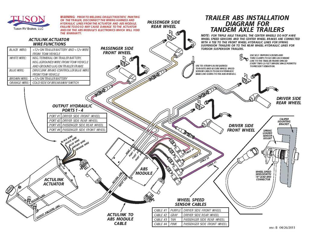
3 Installation of Hydraulic Lines The ActuLink ABS Module has 6 brass 1/8 NPTF male fittings with #3 (3/16 ) female inverted flare tube seat adapters (for 1/8 brake line). These fittings are all clearly labeled and it is critical that the proper hydraulic line is connected to the proper location on the ActuLink ABS Module. On one side of the ActuLink ABS Module, there are two fittings: one is labeled PIN (pressure input) and the other is labeled RET (return line). This side of the ActuLink ABS Module should be positioned to face toward the ActuLink ABS actuator and it is critical that the pressure output of the ActuLink ABS actuator is connected to the pressure input of the ActuLink ABS Module. It is equally critical that the return line of the ActuLink ABS actuator is connected to the return line of the ActuLink ABS Module. On the opposite side the ActuLink ABS Module, there are four fittings: Each is labeled with a number (1,2,3,4). These numbers correspond with a specific brake caliper with which it must be connected. These connections are as follows: Fitting 1: Driver s side front brake caliper Fitting 2: Driver s side rear brake caliper Fitting 3: Passenger s side rear brake caliper Fitting 4: Passenger s side front brake caliper It is critical that each of these lines be properly connected as outlined above. If any line is improperly connected, the ABS system will not work properly. DO NOT use Teflon pipe tape or other type of thread dope when connecting brake tubing or hose. You must hold the ActuLink brass fitting securely in place with the appropriate size wrench when tightening the brake line fitting to the ActuLink ABS Module. Failure to secure the brass fitting may cause damage to the brake line fitting. When installing steel tubing, use care to avoid sharp kinks or bends, which can restrict brake fluid flow causing poor brake response. Double flare the ends of the steel tubing to ensure tight leak proof connections. All steel hydraulic lines should be anchored at two foot intervals to prevent vibration and chafing. Rubber hydraulic hose should be used at points where flexing may occur. Be sure hydraulic hose is positioned so it does not rub against any surface during trailering. Anchor ends of tubing to minimize stress. Follow the instructions of your brake manufacturer when connecting the brake lines to the brake caliper. Connecting ABS Module to Wheel Speed Sensors The ActuLink ABS Module wire harness has four (4) connectors for ABS Wheel Speed Sensors. These connectors are color coded and the proper color must be attached to the proper wheel speed sensor as outlined below: Cable #1 Purple: Driver Side Front Wheel Cable #2 Gray: Driver Side Rear Wheel Cable #3 Tan: Passenger Side Rear Wheel Cable #4 Pink: Passenger Side Front Wheel It is critical that the wheel speed sensor cables are connected as outlined above or the entire towable ABS system will not function properly. Note: For triple axle trailers, the center wheels do not have wheel speed sensors and the center wheel brakes are connected with a tee to the front wheel hydraulic lines for spring suspension trailers or to the rear wheel hydraulic lines for torsion suspension trailers.! Warning! Prior to welding or electrostatic painting on the trailer, disconnect the wiring harness and hydraulic lines from the ActuLink actuator and ABS Module. Failure to do so may cause damage to the actuator and/or the ABS Module s electronics which will void the warranty. Installing Wheel Speed Sensors It is critical that the gap between the end of the wheel speed sensor and the teeth of the tone ring are in very close proximity (no greater than / 1mm). There are two types of mounting hardware available for mounting wheel speed sensors: 1) Tuson s spring loaded bracket, 2) hollow bolt (which may be a integral part of the brake caliper mounting bracket or may be a separate bolt that is installed in an opening in the brake caliper mounting bracket) with a spring clip. Tuson s spring loaded mount comes with shims that are / 1mm thick. Without the shims, the sensor will come into contact with the teeth of the tone ring. Therefore, the shims should be added, one at a time, until the sensor is no longer in contact with the teeth on the tone ring when the rotor is fully installed (with the spindle nut properly installed and pinned with a cotter pin) At that point, rotate the rotor completely to ensure the sensor does not come into contact with the tone ring and that the gap is no greater than / 1 mm.. With non-spring loaded mounts, a / 1mm feeler gauge should be used to obtain the proper gap. Place the feeler gauge between the teeth of the tone ring and the sensor and slide the sensor toward the teeth until it makes contact with the feeler gauge. When the feeler gauge is removed, the barrel spring clip in the sensor mount will hold the sensor in place. Note: When using the hollow bolt with spring clip to mount the wheel speed sensors, the sensors should not slide easily within the hollow bolt as the spring clip must hold it very firmly in place. It should take significant force to move the sensor inward toward the teeth. If the sensor moves easily, that is an indication to replace the spring clip with a new one. If this is not done, the sensor will eventually move from the tone ring teeth and will stop capturing data which will diminish the performance or disable the ABS system.
4
5 Limited Warranty Tuson RV Brakes, LLC (Tuson) warrants the ActuLink ABS module to be free of defects in material and workmanship for a period not to exceed TWO (2) years from the date of sale to the original consumer, or to the first retail purchaser of a trailer on which the ActuLink is installed. Original receipt(s) or other acceptable proof of purchase should be retained by the customer for verification of warranty date. THIS WARRANTY IS NOT TRANSFERABLE. Tuson s obligations under this warranty shall be limited to crediting the account of a direct buying distributor or OEM trailer manufacturer, replacing or repairing ActuLink products which are determined by Tuson to be defective in material or workmanship, within 60 days of receipt of such product by Tuson. Tuson reserves the right to request the product be returned intact, freight prepaid, PRIOR to processing any claim for warranty. Warranty claim must be received by Tuson within 30 days of the discovery of the alleged defect, or within 30 days of the expiration of the warranty, whichever is earlier. Covered repairs or replacements will be made at Tuson s expense. Shipment of replacement product or repaired product by Tuson will be via best available ground shipment carrier. Shipments other than by best available ground shipment carrier, must be requested in writing and must be paid for in advance by the customer. Returned product that is found not to be defective, will be returned at senders expense. This Warranty shall not include any products which have been improperly installed, installed contrary to installation instructions provided with the product, altered, tampered with or changed in any way, or utilized in a manner not approved by Tuson. This Warranty shall not extend to any defects arising from abuse, misuse, accident, improper wiring, or negligence of the installer or the consumer. Refer to the ActuLink ABS Owner s Manual and Installation Instructions that was shipped with the ActuLink ABS. EXCEPT AS EXPRESSLY SET FORTH ABOVE, NO OTHER WARRANTY, EXPRESS OR IMPLIED, AT LAW OR IN EQUITY, IS MADE BY TUSON IN RESPECT OF THE PRODUCT, INCLUDING WITHOUT LIMITATION ANY IMPLIED WARRANTY OF MERCHANTABILITY, FITNESS FOR A PARTICULAR PURPOSE OR ANY OTHER WARRANTY, AND ANY SUCH WARRANTIES ARE EXPRESSLY DISCLAIMED. IN NO EVENT SHALL TUSON BE LIABLE TO PURCHASER OR ANY THIRD PARTY FOR ANY LOST PROFITS, CONSEQUENTIAL, EXEMPLARY, INDIRECT, PUNITIVE, INCIDENTAL, OR SPECIAL DAMAGES OR COSTS (INCLUDING ATTORNEY FEES), OR LOSS OF GOOD WILL RESULTING FROM ANY CLAIM (INCLUDING BUT NOT LIMITED TO ANY CAUSE OF ACTION SOUNDING IN CONTRACT, TORT, NEGLIGENCE, STRICT LIABILITY OR PRODUCT LIABILITY) REGARDING THIS AGREEMENT, EVEN IF THE COMPANY HAS BEEN ADVISED OF THE POSSIBILITY OF SUCH DAMAGES. Some states do not allow the exclusion or limitation of implied warranties, incidental or consequential damages, so the above limitations or exclusions may not apply to you. This Warranty gives you specific rights. You may have other rights, which vary from state to state. If you have a problem with your ActuLink ABS module, take the following steps: 1. Trouble shoot the unit as described in this owner s manual. If a copy of the manual is not readable or is lost, contact your dealer/distributor for a copy. Additional copies of the manual can be ordered from Tuson Corporation for $10.00 plus shipping. Call or copies are available for free online at or 2. If you are still having problems after trouble shooting and you believe you have a valid warranty claim, contact the dealer or distributor where you purchased the product. 22
6 3. If it is deemed the ActuLink ABS should be returned to Tuson for inspection and warranty consideration, the dealer or distributor will make the claim through the ActuLink supplier. If you purchased the ActuLink directly from Tuson s online store, contact customer service at to make a claim. To Make A Claim 1. All claims must include proof of purchase information. The required information is: copy of receipt or itemized bill showing name and address of the purchaser, and date of purchase, product number, serial number. 2. All returns require a Returns Merchandise Authorization (RMA). An RMA number can be obtained by contacting Tuson customer service at or inforvbrakes@tuson.com. You will be asked to provide proof of purchase information per item #1 of this section. 3. The customer, direct account OEM or distributor will return the ActuLink prepaid, securely packed in appropriate packaging. The product must be free of mud, dirt, sand, grease, or other debris, with the brake fluid completely drained from the reservoir. The shipping box must be clearly marked with the RMA number when the unit is returned to Tuson for inspection. 4. If Tuson determines the claim is valid, the ActuLink will be repaired or replaced, or credit will be issued to a direct OEM account or direct distributor. If a labor claim is made, Tuson will issue credit to reimburse for up to one hour of labor, not to exceed $70 to replace the defective unit. 5. If a claim is deemed invalid (See previous page) or the ActuLink is found to work properly, the direct account OEM or direct distributor will be notified and no credit will be issued for the returned ActuLink or for labor. An ActuLink with an invalid warranty claim will be returned to the sender, freight collect, unless otherwise instructed in writing. 23
INSTALLATION, INSTRUCTION AND SERVICE MANUAL
 INSTALLATION, INSTRUCTION AND SERVICE MANUAL Actuator/Brake/Trailer Dealer Please provide to consumer. Consumer Read and follow instructions. Keep with trailer for reference. Page 1 of 7 1. Introduction...
PVI 1800/PVI Residential/Commercial Grid-Tied Photovoltaic Inverter WARRANTY MANUAL. Subject to Change REV , Solectria Renewables
 PVI 1800/PVI 2500 WARRANTY MANUAL Residential/Commercial Grid-Tied Photovoltaic Inverter 2009, Solectria Renewables Subject to Change REV 10.09 1 Product Warranty & RMA Policy 1.1 Warranty Policy The Solectria
PVI 60KW, PVI 82KW, PVI 95KW
 PVI 60KW PVI 82KW PVI 95KW WARRANTY MANUAL Commercial, Grid-Tied Photovoltaic Inverters 2008, Solectria Renewables LLC Subject to Change DOC-020099 rev 024 1 1 Product Warranty & RMA Policy Warranty Policy
TITAN 13 x 2½ BRAKES DUO-SERVO AND FREE BACKING
 INSTALLATION INSTRUCTION AND SERVICE MANUAL Actuator/Trailer Dealer - Please provide these instructions to the consumer. Consumer - Read and follow these instructions. Keep them with the trailer for future
INSTALLATION INSTRUCTIONS
 INSTALLATION INSTRUCTION AND SERVICE MANUAL Actuator/Trailer Dealer - Please provide these instructions to the consumer. Consumer - Read and follow these instructions. Keep them with the trailer for future
WARRANTY POLICY. Grid-Tied Photovoltaic Inverters. Revision D. 2014, Solectria Renewables, LLC DOCIN
 WARRANTY POLICY Revision D 2014, Solectria Renewables, LLC DOCIN-070360 1 Product Warranty & RMA Policy 1. Warranty Policy Warranty Registration: It is important to have updated information about the inverter
PREMIER, MARINE, & STANDARD
 INSTA LLATION INSTRUCTION AND SERVICE MANUAL I TITAN 12" x 2" BRAKES FREE BACKING. UNI-SERVO. DUO-SERVO PREMIER, MARINE, & STANDARD Limited Warranty TITAN Inc. ("TITAN') warrants its products to be free
INSTALLATION & OPERATING INSTRUCTIONS: REVOLUTION SPINEBOARD ATTACHMENT WARNING
 INSTALLATION & OPERATING INSTRUCTIONS: REVOLUTION SPINEBOARD ATTACHMENT LOAD CAPACITY: 500 LBS [227 kg] MANDATORY: LEAVE THIS MANUAL WITH LIFT OWNER WARNING 1. READ AND FOLLOW ALL INSTRUCTIONS. LIFT SAFETY
EZ-R7 T-Plug. Universal 7-Pin Heavy Duty Plug For Vehicles equipped with 7-Way Trailer Connectors. Installation Instructions and Product Warranty
 EZ-R7 T-Plug Universal 7-Pin Heavy Duty Plug For Vehicles equipped with 7-Way Trailer Connectors Installation Instructions and Product Warranty Professional Installation Required Thank you for purchasing
Transmission Guardian
 Transmission Guardian Thank you for purchasing the Transmission Guardian from Bowler Performance Transmissions. We hope you are 100 percent satisfied with your purchase and if for any reason you are not,
DWS404 DWS524 DWS654 DWS684 DWS694. DWS SERIES INSTALLATION/OWNER'S MANUAL Car Audio Speakers
 DWS404 DWS524 DWS654 DWS684 DWS694 DWS SERIES INSTALLATION/OWNER'S MANUAL Car Audio Speakers PREPARATION Safety Guidelines Thank you for purchasing the DWS Series car speakers. Although Dual has attempted
DUAL WIDEBAND AIR/FUEL RATIO GAUGE Product Numbers: GS-W702W_Dual, GS-C702W_Dual, GS-T702W_Dual
 Installation Instructions Tech Support: 856.768.8300 TechSupport@GlowShiftGauges.com DUAL WIDEBAND AIR/FUEL RATIO GAUGE Product Numbers: GS-W702W_Dual, GS-C702W_Dual, GS-T702W_Dual (1) Gauge (2) Controllers
Installation Power Management Unit Battery Cables and Battery Harness
 Installation Power Management Unit Battery Cables and Battery Harness Important Safety Messages SAVE THESE INSTRUCTIONS - This manual contains important instructions that should be followed during installation
10 Year Limited Warranty
 Power. On Your Terms. 10 Year Limited Warranty PHI 2.7 TM PHI 3.5 TM 60A SIMPLIPHI POWER, INC. REV020618 10 Year Limited Warranty: PHI 2.7 TM PHI 3.5 TM 60A 24V 48V Limited Pro-Rated Warranty Coverage
Installation Instructions
 85-4592 rev. 08 02-18 Installation Instructions Thank you for purchasing our sway bar kit. Please read through these instructions before installation. Auxiliary Rear Anti-Sway Bar Kit for Ford F53 part
Guardian Steel Gear Shaft Coupling
 Guardian Steel Gear Shaft Coupling P-8609-GC GUA-MRK-DOC-026 Service & Installation Instructions TABLE OF CONTENTS NOTICES AND WARNINGS PAGE 2 SECTION 1 COUPLING OVERVIEW PAGE 3 SECTION 2 TOOLS/MATERIALS
Power. On Your Terms.
 Power. On Your Terms. 10 YEAR LIMITED WARRANTY PHI 1310 TM 1 SIMPLIPHI POWER, INC. REV102016 10 YEAR LIMITED WARRANTY: PHI 1310 TM LIMITED PRO-RATED WARRANTY COVERAGE The SimpliPhi Power PHI 1310 as supplied
Installation Instructions
 85-3214 rev. 07 03-11 Installation Instructions Thank you for purchasing this anti-sway bar kit. Please read through these instructions before installation. Rear Anti-Sway Bar Kit Freightliner FL Series
MANUAL SERVICE MANUAL FOR HYDRASTAR HYDRAULIC TRAILER BRAKE ACTUATORS
 MANUAL 440-1008 SERVICE MANUAL FOR HYDRASTAR HYDRAULIC TRAILER BRAKE ACTUATORS THIS DOCUMENT TO BE USED FOR HBA-10, HBA-12, HBA-16, MHBA-10, MHBA-12, MHBA-16 ACTUATORS ECN 04007 Manual 440-1008 Rev E Page
Read and follow all instructions. Safety can only be ensured if the walker is assembled and operated according to these instructions.
 Aqua Walker 9889 Garrymore Ln Missoula, MT 59808 888-687-3552 +1-406-549-0769 www.aquacreek.com Manual PART #: F-605UW 300 LB. [136 kg] MAXIMUM WEIGHT CAPACITY MANDATORY LEAVE THIS MANUAL WITH WALKER OWNER
Installation Instructions
 85-3414 rev. 02 11-09 Installation Instructions Thank you for purchasing this anti-sway bar kit. Please read through these instructions before installation. Rear Anti-Sway Bar Kit for the Monaco Diplomat
60 PSI Boost Gauge. For Product Numbers: MT-DV01_60, MT-WDV01_60
 60 PSI Boost Gauge For Product Numbers: MT-DV01_60, MT-WDV01_60 Red: 12v Constant (un-switched) Source (+) Orange: 12v Dimmer (switched) Source (+) (optional) White: 12v Ignition (switched) Source (+)
Installation Instructions
 85-3195 rev. 12 04-18 Installation Instructions Thank you for purchasing this antisway bar kit. Please read through these instructions before installation. Part #1139-117 Rear Anti-Sway Bar Kit 1½ diameter
Installation Instructions
 85-3209 rev. 07 03-11 Installation Instructions Thank you for purchasing this anti-sway bar kit. Please read through these instructions before installation. Front Anti-Sway Bar Kit for Workhorse W22, Holiday
Installation Instructions
 85-3910 rev. 03 01-18 Installation Instructions Thank you for purchasing the antisway bar kit. Please read through these instructions before installation. Rear Anti-Sway Bar Kit for Ford F-250/F-350 part
ATTENTION: PLEASE READ AND UNDERSTAND ALL INSTRUCTIONS AND WARNINGS BEFORE ASSEMBLING, INSTALLING OR USING THIS PRODUCT.
 INSTALLATION MANUAL PROMASTER MOUNTING CHANNEL KIT (2115-0-01) ATTENTION: PLEASE READ AND UNDERSTAND ALL INSTRUCTIONS AND WARNINGS BEFORE ASSEMBLING, INSTALLING OR USING THIS PRODUCT. 1/2 in Wrench/ Socket
Installation Instructions
 85-3909 rev. 01 09-09 Installation Instructions Thank you for purchasing this anti-sway bar kit. Please read through these instructions before installation. Rear Anti-Sway Bar Kit for Chevrolet G30 part
General Guidelines. Instructions for Part # SC-SWING-AWAY-V2. Safety
 Instructions for Part # SC-SWING-AWAY-V2 General Guidelines It is the user s responsibility to read and follow all instructions. Keep these instructions with the product at all times and review before
INSTALLATION/OWNER'S MANUAL DP " Woofer in Enclosure
 INSTALLATION/OWNER'S MANUAL DP1000 10" Woofer in Enclosure Installation Thank you for purchasing the DP1000 10" Woofer with enclosure. Although Dual has attempted to make sure all of the information contained
Customer Support
 Portable auxiliary air tanks owner's Manual aux05 aux05a aux10 WWW.CALIFORNIAAIRTOOLS.COM Customer Support 1-866-409-4581 TAbLe OF CONTeNTS INTROduCTION IntroductIon Important Safety InStructIonS components
AWE S-FLO Carbon Intake System Mini F5X. AWE website here
 Thank you for purchasing the AWE S-FLO Carbon Intake System for the 2014+ Mini F5X. For up to the minute fitment information, be sure to visit the Mini section of the AWE website. As always, AWE Performance
Installation Instructions
 85-4209 rev. 05 11-18 Installation Instructions Thank you for purchasing this anti-sway bar kit. Please read through these instructions before installation. Factory Replacement Anti-Sway Bar Kit part #1129-135
HATCHGRIP Installation Instructions/Operation and Maintenance Manual
 HATCHGRIP Installation Instructions/Operation and Maintenance Manual Models: HTG-PCG Contact Information Table of Contents: Safety Precautions... 2 Product Information... 2 Operation... 3 Installation
SUNTURA SOLAR TRACKER
 WindyNation SUNTURA SOLAR TRACKER SOT-TRKS-NF User s Manual Page 1 of 10 WindyNation 08/09/2012 Table of Contents 1 Introduction... 3 1.1 Limited Warranty... 3 1.2 Restrictions... 3 1.3 Warranty Claims
Installation / Operation Instructions Sunnex ORION Series Exam Lights
 Installation / Operation Instructions Sunnex ORION Series Exam Lights OR-120 OR-127 OR-220 OR-227 Models: OR-300 OR-400 OR-500 OR-600 1. APPLICATIONS The Sunnex ORION Series light was designed specifically
20250 Module Installation Guide
 20250 Module Installation Guide 2013.5-2017 RAM 6.7L Cummins Up to 90HP Gain 1-3 MPG Fuel Savings AgDieselSolutions.com Adjustable switch connector Power +12 volts (Red wire) & Ground (Black wire) Injector
Installation Instructions
 85-3847 rev. 01 09-09 Installation Instructions Thank you for purchasing this anti-sway bar kit. Please read through these instructions before installation. Front Anti-Sway Bar TruTrac Bar Combo Kit for
Deluxe Hitch 3-Bike Rack Instructions for Part # BC-3581
 General Guidelines Deluxe Hitch 3-Bike Rack Instructions for Part # BC-3581 It is the user s responsibility to read and follow all instructions. Keep these instructions with the product at all times and
LIFT NAME PART NUMBER SETBACK (min) SETBACK (max)
 SETBACK (max)") Revolution 9889 Garrymore Ln Missoula, MT 59808 888-687-3552 +1-406-549-0769 www.aquacreek.com Wheelchair Attachment PART #: F-705S3 WEIGHT CAPACITY: 350 POUNDS - STANDARD REVOLUTION 300 POUNDS - DEEP
Revolution 9889 Garrymore Ln Missoula, MT 59808 888-687-3552 +1-406-549-0769 www.aquacreek.com Wheelchair Attachment PART #: F-705S3 WEIGHT CAPACITY: 350 POUNDS - STANDARD REVOLUTION 300 POUNDS - DEEP
PART NUMBER: F-706RLSS REVOLUTION LIFT: SLING-SEAT OPTION
 PART NUMBER: F-706RLSS REVOLUTION LIFT: SLING-SEAT OPTION 500 LB. [227 kg] MAXIMUM CAPACITY MANDATORY LEAVE THIS MANUAL WITH LIFT OWNER - WARNING- IMPORTANT SAFETY INSTRUCTIONS 1. READ AND FOLLOW ALL INSTRUCTIONS.
Female Plug. connecting to Fuel Quantity
 **Ag Diesel Solutions recommends replacing the Transorb/Suppressor Diode before the installation of this module*** Red wire = 12V Constant power. Male Plug connecting to Fuel Quantity Valve Black wire
HR-20P Pneumatically Controlled Pressure Regulator
 HR-20P Pneumatically Controlled Pressure Regulator Instruction and Service Manual Hydroplex Corporation 230 West Gloria Switch Rd. Lafayette, LA 70507 337-233-0626 www.hydroplexpumps.com I. General Instructions
Installation Instructions
 85-4341 rev. 04 10-15 Installation Instructions Thank you for purchasing this antisway bar kit. Please read through these instructions before installation. Rear Anti-Sway Bar Kit for Chevy 2500/3500/4500
SOLAR DASH CHARGING SYSTEM USER GUIDE
 SOLAR DASH CHARGING SYSTEM Doc 1.01 INST049 INSTALLATION STEP 1 Place 20 watt solar panel in the dash of the vehicle facing up. Note: For ideal results position the vehicle in a manner in which the solar
EZ Carrier 3. Owner s Manual. Keep instructions for future reference
 EZ Carrier vv Owner s Manual Keep instructions for future reference Introduction The EZ Carrier provides all the flexibility you may need to transport your mobility scooter. The features include: The capability
MODEL FIXED MOTOR BRACKET
 MODEL 55-0027 FIXED MOTOR BRACKET INSTALLATION MANUAL REV 12/15 CUSTOMER MUST RECEIVE THIS MANUAL AFTER INSTALLATION INSTALLATION PROCEDURES Congratulations, you have just purchased one of the finest outboard
Heavy Duty Steel Motorcycle Carrier. Instructions for Part # MCC-600
 Heavy Duty Steel Motorcycle Carrier Instructions for Part # MCC-600 General Guidelines It is the user s responsibility to read and follow all instructions. Keep these instructions with the product at all
Universal Bevel Drives Service Manual
 Engineering Service Bulletin #SB241202 Universal Bevel Drives Service Manual Cautions Following are some general cautions. All personnel shall use safe and sound practices and take all necessary precautionary
Guardian FH Flywheel Coupling
 Guardian FH Flywheel Coupling P-8606-GC GUA-MRK-DOC-015 Service & Installation Instructions TABLE OF CONTENTS NOTICES AND WARNINGS PAGE 2 SECTION 1 COUPLING OVERVIEW PAGE 3 SECTION 2 TOOLS/MATERIALS REQUIRED
AWE SwitchPath Exhaust System Ford Focus RS 2.3T. AWE website here
 Thank you for purchasing the AWE SwitchPath Exhaust System for the 2016+ Ford Focus RS 2.3T. For up-to-the-minute fitment information, be sure to visit the Ford Focus section of the AWE website. As always,
TERMS OF USE TERMS AND CONDITIONS. Plumbing and Heating Products (PL-WR)
") TERMS OF USE 1. Watts pricing and product data is subject to change without notice and such changes supersede all previous versions. 2. Watts data is to be used as provided. Watts is not responsible for
TERMS OF USE 1. Watts pricing and product data is subject to change without notice and such changes supersede all previous versions. 2. Watts data is to be used as provided. Watts is not responsible for
Compressor Clutch Replacement Procedure
 Clutch Replacement Procedure P-1401-WE 819-0316 Installation Instructions An Altra Industrial Motion Company Warner Replacement Clutches for the following compressors: Denso 6E171 10P15 6P148 6C17 Ford
WARNING!!! READ AND UNDERSTAND ALL INSTRUCTIONS BEFORE PROCEEDING. MAKE SURE THAT YOU HAVE ALL TOOLS AND PARTS BEFORE BEGINNING THE INSTALLATION.
 INSTALLATION INSTRUCTIONS FOR 2007-2015 JEEP JK 3 SUSPENSION LIFT SYSTEM PART NUMBER 587 WARNING!!! READ AND UNDERSTAND ALL INSTRUCTIONS BEFORE PROCEEDING. MAKE SURE THAT YOU HAVE ALL TOOLS AND PARTS BEFORE
Light Duty Electronic Air Command
 2491 PSI BAR Light Duty Electronic Air Command INSTALLATION INSTRUCTIONS Congratulations on your purchase of a Light Duty Electronic Air Command kit. This kit was designed to provide inflation control
SUNTURA HD SOLAR TRACKER
 WindyNation SUNTURA HD SOLAR TRACKER SOT-TRKS-NFHD User s Manual Page 1 of 11 WindyNation 08/09/2012 Table of Contents 1! Introduction... 3! 1.1! Limited Warranty... 3! 1.2! Restrictions... 3! 1.3! Warranty
Installation Instructions
 85-3700 rev. 08 05-18 Installation Instructions Thank you for purchasing this antisway bar kit. Please read through these instructions before installation. Front Anti-Sway Bar Kit for the F53 Chassis part
Guardian HH Shaft Coupling
 Guardian HH Shaft Coupling P-8611-GC GUA-MRK-DOC-028 Service & Installation Instructions TABLE OF CONTENTS NOTICES AND WARNINGS PAGE 2 SECTION 1 COUPLING OVERVIEW PAGE 3 SECTION 2 TOOLS/MATERIALS REQUIRED
Guardian Taper Grid Shaft Coupling
 Guardian Taper Grid Shaft Coupling P-8608-GC GUA-MRK-DOC-025 Service & Installation Instructions TABLE OF CONTENTS NOTICES AND WARNINGS PAGE 2 SECTION 1 COUPLING OVERVIEW PAGE 3 SECTION 2 TOOLS/MATERIALS
AXS609 AXS612 AXS514 AXS SERIES. INSTALLATION/OWNER'S MANUAL Car Audio
 AXS609 AXS612 AXS514 AXS SERIES INSTALLATION/OWNER'S MANUAL Car Audio PREPARATION Safety Guidelines Thank you for purchasing the AXS Series car speakers. Although Axxera has attempted to make sure all
READ THIS MANUAL CAREFULLY BEFORE USING THE PUMP
 OWNER S MANUAL Pond Pump READ THIS MANUAL CAREFULLY BEFORE USING THE PUMP Important Notice: This manual contains important information about the installation, operation and safe use of this product. This
12 Volt Utility Controller for 4, 6, or 8 Brakes No
 12 Volt Utility Controller for 4, 6, or 8 Brakes No. 1300-76 P-1396-WE 819-0301 Installation Instructions An Altra Industrial Motion Company Contents Introduction... 2 Installation... 3 Mounting Under
Product/ Title Guardian Super Flex Shaft Coupling Product/ Title
 Product/ Title Guardian Super Flex Shaft Coupling Product/ Title GUA-MRK-DOC-027 P-XXXX-GC Service&&Installation Installation Instructions Instructions Service An Altra Industrial Motion Company TABLE
Grapple Kit Install & Grapple Bucket Manual
 Grapple Kit Install & Grapple Bucket Manual Model # Serial # Rev. 10/13 Rylind Manufacturing, Inc. 2801 Youngfield St Suite 250 Golden, CO 80401 Business/Sales Offices: 303-979-3548 Manufacturing Plant:
EZR7 Universal 7-Pin Heavy Duty Plug Installation Instructions and Product Warranty Professional Installation Required
 EZR7 Universal 7-Pin Heavy Duty Plug Installation Instructions and Product Warranty Professional Installation Required Thank you for purchasing our EZ-U7PHD trailer plug! Your choice displays your recognition
AWE Resonated Touring Edition Ford Focus RS 2.3T. AWE website here
 Thank you for purchasing the AWE Resonated Touring Edition exhaust system for the 2016+ Ford Focus RS 2.3T. For up-to-the-minute fitment information, be sure to visit the Ford Focus section of the AWE
Fifth Wheel Power Hitch Operations Manual
 Fifth Wheel Power Hitch Operations Manual ITD1253 Fifth Wheel Power Hitch 208 587 7960 www.intheditch.com This page is intentionally left blank. Operations Manual 1 TABLE OF CONTENTS TABLE OF CONTENTS...
Installation Instructions
 85-3207 rev. 03 05-06 Installation Instructions Thank you for purchasing this anti-sway bar kit. Please read through these instructions before installation. Rear Anti-Sway Bar Kit for the Freightliner
A S S E M B L Y I N S T R U C T I O N S
 A S S E M B L Y I N S T R U C T I O N S Please Do Not Return This Product to the Store! Contact Escalade Sports customer service department at: Phone: 1-888-USA-GOAL Toll-Free! Fax: 1-866-873-3536 Toll-Free!
MODEL V-24 OWNER'S MANUAL PARTS
 OWNER'S MANUAL MODEL V-24 PARTS NOTE: MANUAL including SPECIFICATIONS, subject to change without notice All ratings specified are based on structural factors only, not vehicle capacities or capabilities.
TS69 TS65 TS55 TS45 TS5768 TS SERIES INSTALLATION/OWNER'S MANUAL
 TS69 TS65 TS55 TS45 TS5768 TS SERIES INSTALLATION/OWNER'S MANUAL Car Audio Speakers TS SERIES PREPARATION Getting Started Thank you for purchasing the TS Series car speakers. Although Dual has attempted
LB LB LLY LLY 1000
 6 November 2006 GMC/Chevy Allison Performance Transmission 1 BD PERFORMANCE TRANSMISSION Allison Installation Instructions 2WD Transmissions 4WD Transmissions 1064702 2000-2003 LB7 1000 1064704 2000-2003
DM1016S INSTALLATION/OWNER'S MANUAL 10" Marine DVC Subwoofer
 DM1016S INSTALLATION/OWNER'S MANUAL 10" Marine DVC Subwoofer DM1016S INSTALLATION Preparation/Installation Please read entire manual before installation. Before You Start Disconnect negative battery terminal.
Rig Master Power by Mobile Thermo Systems Inc.
 RigMaster Power Dealer Warranty Policy The Limited Warranty This limited warranty applies to the RigMaster Auxiliary Power Unit (RigMaster APU) which consists of the following components: 1. The generator
30100 Module Installation Guide L
 30100 Module Installation Guide 1997-2006 12.0L Mack Engines Up to 30% HP Gain 10-20% Fuel Savings AgDieselSolutions.com 1997-2006 Mack 12.0L Engine Module +12 volts red wire. Ground black wire Injector
24V Solar Charger. Instructions READ CAREFULLY Garrymore Ln Missoula, MT
 24V Solar Charger 9889 Garrymore Ln Missoula, MT 59808 888-687-3552 +1-406-549-0769 www.aquacreek.com Instructions PART #: F-044SCH (For use with Pro Pool, Ranger, Ambassador & Pathfinder) MANDATORY LEAVE
CU6703 Module Installation Guide
 Up to 30% More Horsepower 10-20% Fuel Savings Cummins 6.7L Tier III Engines CU6703 Module Installation Guide AgDieselSolutions.com MAP sensor male and female connectors. Power and Ground wires. Module
Mercedes MBE 906/ L & 7.2L Engine Module. Part # Installation Instructions
 1999-2006 Mercedes MBE 906/926 6.4L & 7.2L Engine Module Part # 15000 Installation Instructions 15000_revC 1999-2006 Mercedes 6.4L & 7.2L Engine Module +12 volts red wire. Ground black wire Injector Terminals
AWE Track Edition Exhaust System Ford Focus ST 2.0T. AWE website here
 Thank you for purchasing the AWE Track Edition Exhaust System for the 2013+ Ford Focus ST 2.0T. For up-to-the-minute fitment information, be sure to visit the Ford Focus section of the AWE website. As
Compressor Clutch Replacement Procedure
 P-1411 819-0361 Compressor Clutch Replacement Procedure Installation Instructions World Clutch with Unidamp Armature for Ford FX-15 and FS-10 Compressors and all Denso Models with 30mm bearing fit. Keep
GM 6.6L Duramax. Up to 90HP Gain. AgDieselSolutions.com
 21700 Module Installation Guide 2017 GM 6.6L Duramax *L5P* Up to 90HP Gain 1-3 MPG Fuel Savings AgDieselSolutions.com Adjustable Switch Female Fuel Pressure Sensor Connector Male Fuel Pressure Sensor Connector
Users Guide for Ac-sync
 Problem solved. Users Guide for Ac-sync Thank you for choosing Anywhere Cart! The AC-SYNC is designed to sync, charge and store 1-36 ipads or tablets. Adjustable device divider bays allow fitment of any
AWE Tuning W205 C300 SwitchPath Edition or Touring Edition cat back exhaust system.
 Thank you for your purchase of the AWE Tuning 2015+ W205 C300 SwitchPath Edition or Touring Edition cat back exhaust system. For up to the minute fitment information, be sure to visit the W205 C300 section
PATRIOT LIFT CO. ON-Lift Installation Guidelines
 PATRIOT LIFT CO. ON-Lift Installation Guidelines Choosing A Landing Gear Type It is important to note that the Patriot Lift Systems operates more efficiently for speed /timing with some landing gear types
HIGH DUMP ROLL-OUT BUCKET
 HIGH DUMP ROLL-OUT BUCKET Model # Serial # Rev. 01/14 Rylind Manufacturing, Inc. 2801 Youngfield St Suite 250 Golden, CO 80401 Business/Sales Offices: 303-979-3548 Manufacturing Plant: 970-522-2859 www.rylind.com
Installation Guide. Marine Filter SURT023M SURT024M
 Installation Guide Marine SURT023M SURT024M suo0738a Product Description The APC by Schneider Electric Marine Application reduces the EMI (electro magnetic interference), produced by a connected that
INSTALLATION INSTRUCTIONS FOR JEEP COMMANDER / GRAND CHEROKEE 2" SUSPENSION LIFT KIT PART NUMBER 581
 INSTALLATION INSTRUCTIONS FOR 005-010 JEEP COMMANDER / GRAND CHEROKEE " SUSPENSION LIFT KIT PART NUMBER 51 WARNING!!! READ AND UNDERSTAND ALL INSTRUCTIONS BEFORE PROCEEDING. MAKE SURE THAT YOU HAVE ALL
BATHROOM ACCESSORIES
 BATHROOM ACCESSORIES ORCA HARDWARE WARRANTY Orca Hardware warrants its products manufactured to be free from defects in materials and workmanship for a period of ten (10) years from the date of purchase,
LoadMaxx. Installation Guide. For Air Ride Trailers. Air-Weigh Customer Support: PN R0
 LoadMaxx Installation Guide For Air Ride Trailers Air-Weigh Customer Support: 888-459-3247 PN 901-0158-000 R0 x1 Table of Contents LoadMaxx Trailer Overview...1 Installation Overview...1 Mounting the Scale...2
Kit INSTALLATION GUIDE. For maximum effectiveness and safety, please read these instructions completely before proceeding with installation.
 Kit 25690 MN-369 (111512) ECR 8349 INSTALLATION GUIDE For maximum effectiveness and safety, please read these instructions completely before proceeding with installation. Failure to read these instructions
750 lb. Capacity Extra-Large Game Cart Instructions for Part # GAME-CART-HD
 General Guidelines 750 lb. Capacity Extra-Large Game Cart Instructions for Part # GAME-CART-HD It is the user s responsibility to read and follow all instructions. Keep these instructions with the product
Model T2642 Wall Mount. Television Wall Mount with Tilt Option
 Model T2642 Wall Mount Television Wall Mount with Tilt Option Getting Started Introduction Congratulations on the purchase of your new Audio Solutions T2642 Television Wall Mount. For maximum benefit,
POWER GEAR SLIDE-OUT MANUAL
 POWER GEAR SLIDE-OUT MANUAL Operation Guide FLUSH FLOOR SLIDE-OUT SYSTEM FOR AMERICAN COACH PRODUCTS 82-S0220-01 Rev. 1 AMERICAN COACH SLIDE-OUT MANUAL FLUSH FLOOR SYSTEM TABLE OF CONTENTS SECTION PAGE
15100 Module Installation Guide Mercedes EPA07 w/dpf
 15100 Module Installation Guide 2007-2009 Mercedes EPA07 w/dpf 7.2L Engines Up to 30% HP Gain 10-20% Fuel Savings AgDieselSolutions.com 2007-2009 Mercedes 7.2L Engine Module +12 volts red wire. Ground
RANGE HOODS USER INSTRUCTIONS
 RANGE HOODS USER INSTRUCTIONS Model: Advanta Pro III 30 & 36 IMPORTANT SAFETY INSTRUCTIONS Carefully read the following important information regarding installation safety and maintenance. Keep these instructions
Installation Instructions
 85-3511 rev. 04 11-15 Installation Instructions Polyurethane Bushing Kit for Ford F-53 (Front) (replaces OE bushings and brackets) part #4139-127 1-5/8 diameter INTRODUCTION Thank you for purchasing this
Utility Controller Hand Air Operated
 Utility Controller Hand Air Operated P-1395 819-0288 Installation Instructions Introduction The Warner Electric air/manual Utility Controller combines manual and automatic (air) actuation for the operation
General Guidelines. Parts. Motorcycle Wheel Balancer & Truing Stand Instructions for Part # BW-WB-30. Tools Required
 Motorcycle Wheel Balancer & Truing Stand Instructions for Part # BW-WB-30 General Guidelines It is the user s responsibility to read and follow all instructions. Keep these instructions with the product
22421 SPORT SWAY BAR SET TOYOTA COROLLA
 22421 SPORT SWAY BAR SET 98-01 TOYOTA COROLLA Thank you for your purchase from our line of Corolla parts. Please call us at (877) 4NO-ROLL if you have any questions regarding the service or installation
LUBRICATOR GUN INSTRUCTIONS-PARTS LIST. 10,000 psi (700 bar) Maximum Delivery Pressure. Detachable-type
 Maximum Delivery Pressure. Detachable-type") INSTRUCTIONS-PARTS LIST 306 460 INSTRUCTIONS This manual contains important warnings and information. READ AND KEEP FOR REFERENCE. Rev. E Supercedes D Detachable-type LUBRICATOR GUN 10,000 psi (700 bar)
INSTRUCTIONS-PARTS LIST 306 460 INSTRUCTIONS This manual contains important warnings and information. READ AND KEEP FOR REFERENCE. Rev. E Supercedes D Detachable-type LUBRICATOR GUN 10,000 psi (700 bar)
Installation Instructions
 85-5029 rev. 03 06-17 Installation Instructions Thank you for purchasing our anti-sway bar kit. Please read through these instructions before installation. Rear Anti-Sway Bar Kit for Workhorse W22, Holiday