Please read all of the installation instructions carefully before installing the product. Improper installation will void manufacturer s warranty.
|
|
|
- Spencer Harris
- 5 years ago
- Views:
Transcription

1 TM 1
2 What s in the Box? Note: Configuration will vary depending what item options you select. ire 1 Color Sony CCD night vision weather proof backup camera 1 16 Camera Cable 1 Power Connection Wire
3 Table of Contents Introduction...4 Safety Information Before Beginning Installation...8 Installation Guide Adjustable Grid Line...11 Installation and Wiring...12 Splicing...13 Positioning Troubleshooting...15 Camera Dimensions...16 Camera Specifications...17 Warranty...18 Disclaimer
4 Introduction Please read all of the installation instructions carefully before installing the product. Improper installation will void manufacturer s warranty. Congratulations on purchasing a Rear View Backup Camera System! With this manual you will be able to properly install and operate the unit. The Backup Camera System is intended to be installed as a supplemental aid to the rear view mirror in your vehicle. The Backup Camera System should not be used as a substitute for the standard rear view mirror or for any other mirror in your vehicle. In some jurisdictions, it is unlawful for a person to drive a motor vehicle equipped with a TV viewer or screen located forward of the back of the driver s seat or in any location that is visible, directly or indirectly, to the driver while operating the vehicle. 4 REAR VIEW SAFETY
5 Safety Information Please read the entire manual and follow the instructions and warnings carefully. Failure to do so can cause serious damage and/or injury, including loss of life. Be sure to obey all applicable local traffic and motor vehicle regulations as it pertains to this product. Improper installation will void manufacturer s warranty. USAGE The Rear View Camera System is designed to help the driver safely detect people and/or objects helping to avoid damage or injury. However, you the driver, must use it properly. Use of this system is not a substitute for safe, proper or legal driving. Never back up while looking at the monitor alone. You should always check behind and around the vehicle when backing up, in the same way as you would if the vehicle did not have the Rear View Reverse With Confidence Camera System. If you back up while looking only at the monitor, you may cause damage or injury. Always back up slowly. The Rear View Camera System is not intended for use during exstensive back-up maneuvers or backing into cross traffic or pedestrian walkways. Please, always remember, the area displayed by the Rear View Camera System is limited. It does not display the entire panorama that is behind you. 5
6 Safety Information INSTALLATION Electric shock or product malfunction may occur if this product is installed incorrectly. Use this product within the voltage range specified. Failure to do so can cause electronic shock or product malfunction. Take special care when cleaning the monitor. Make sure to firmly affix the product before use. If smoke or a burning smell is detected, disconnect the system immediately. Where the power cable may touch a metal case, cover the cable with a friction tape. A short circuit or disconnected wire may cause a fire. 6 While installing the Rear View System be careful with the wire positioning in order to avoid wire damage. The Rear View System should only be used when the vehicle is in reverse. Do not watch movies or operate the monitor while driving; as it may cause an accident. Do not install the monitor where it may obstruct drivers view or obstruct an air bag device. Dropping the unit may cause possible mechanical failure. REAR VIEW SAFETY
7 Safety Information If you have questions about this product, contact: Customer Service: Rear View Safety 1797 Atlantic Avenue Brooklyn, NY Tel: IN NO EVENT SHALL SELLER OR MANUFACTURER BE LIABLE FOR ANY DIRECT OR CONSEQUENTIAL DAMAGES OF ANY NATURE, OR LOSSES OR EXPENSES RESULTING FROM ANY DEFECTIVE PRODUCT OR THE USE OF ANY PRODUCT. Reverse With Confidence 7
8 Before You Begin Installation Before drilling please check that no cable or wiring is on the other side of the wall. Please clamp all wires securely to reduce the possibility of them being damaged while vehicle is in use. Keep all cables away from hot or moving parts and electrical noisy components. We recommend doing a benchmark test before installation to insure that all components are working properly. Step 1: Choose the monitor and camera locations. Step 2: Install all cables in vehicle, when necessary a 0.8 (20mm) hole should be drilled for passing camera cable through vehicles walls. Install split grommets where applicable. Step 3: Once all cables and wiring have been properly routed, perform a system function test by temporarily connecting the system. If the system seems to not be operating properly see troubleshooting (page 15). 8 REAR VIEW SAFETY
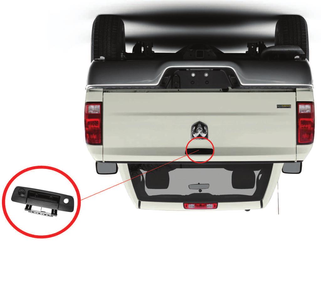
9 Installation Guide Camera & Cable When installing the camera at the rear of the vehicle, remove the existing tailgate handle and replace with the tundra tailgate handle. Be sure to position the cable properly. The aviation camera cable uses aircraft grade connectors which means the camera cable can be exposed to all weather elements. Do not run the cable over sharp edges, do not kink the cable and keep away from HOT and rotating parts. Fasten all cables and secure all excess cable. Connect camera to the camera extension cable which runs inside the vehicle. Attach camera to the center of the license plate are using the screws provided and adjust the angle. Figure 1.1 Wiring After connecting the camera to the "camera cable" the camera should be plugged into AV2 input. Connect the RED 12V power wire to a an ignition power source and the BLACK 12V ground wire to a chassis ground. The GREEN wire is the REVERSE trigger wire. Connect this wire to the vehicle s backup light circuit to activate the rear-view image whenever the vehicle shifts into reverse. To connect a second camera, connect it to AV1 and it can be turned on by pressing the power button on the monitor. Figure 1.2 Reverse With Confidence 9
10 Installation Guide Safety Before drilling, be sure no cable or wire is on the other side. Feed as much cable as possible into vehicle & clamp securely. This reduces the possibility of cable being hooked or snagged. Camera: Drill a 20mm (0.8in) diameter hole into vehicle body near the camera and bracket. Insert camera cable into vehicle (be careful not to kink cable) and fit grommet into hole. Apply sealant around grommet to increase resistance to water penetration. 10 REAR VIEW SAFETY

11 Adjustable Grid Line Reverse With Confidence 11

12 Installation and Wiring Figure 1.1 Figure REAR VIEW SAFETY
13 Splicing Red - Power (+) 2. Yellow - Video 3. Green - Mirror / Normal Imaging 4. White - Audio 5. Black - Ground (-) Reverse With Confidence 13

14 Positioning 14 REAR VIEW SAFETY
15 Troubleshooting No Image On Screen Do a hard reset, unplug all cables and power cables, leave out for 1 minute and then re-connect them. Check to ensure that the connection to the camera is tight. Verify camera cable is plugged into port labeled Backup Camera Verify that the green positive trigger on power harness is put to power 12v+. Verify camera is on correct camera input Verify cable is connected to monitor Verify camera is connected to cable Connect known working camera and cable to monitor. Verify Green trigger is receiving power Reverse With Confidence 15
 x 2.")
16 Camera Dimensions 2.75" (H) x 9.15" (L) x 2.95" (D) 16 REAR VIEW SAFETY
17 Camera Specifications Camera 1/3 SONY IC Sensor Current Consumption MAX: 150mA Sensor CMD-III, 1/4 Resolution (TV Lines) 420 Minimum illumination 0.5 Lux Angle 170 Effective Pixels 648*488 TV System NTSC Video Output Full color vdeo out: 1.0Vp-p 75(ohm) load Working Voltage DC9-16V Video Color Full color Water Proof IP67-IP68 Operating Temperature -30 C to +70 C Parking guar line On/Off Switchable Image Mirror Reverse With Confidence 17
18 Warranty One Year Warranty Rear View Safety Inc. warrants this product against material defects for a period of one year from date of purchase. We reserve the right to repair or replace any such defective unit at our sole discretion. Rear View Safety Inc. is not responsible for a defect in the system as a result of misuse, improper installation, damage or mis-handling of the electronic components. Rear View Safety Inc. is not responsible for consequential damages of any kind. This warranty is void if: defects in materials or workmanship or damages result from repairs or alterations which have been made or attempted by others or the unauthorized use of nonconforming parts; the damage is due to normalware and tear, this damage is due to abuse, improper maintenance, neglect or accident: or the damage is do to use of the Rear View Safety Inc. system after partial failure or use with improper accessories. Warranty Performance DURING THE ABOVE WARRANTY PERIOD, SHOULD YOUR Rear View Safety PRODUCT EXHIBIT A DEFECT IN MATERIAL OR WORKMANSHIP, SUCH DEFECT WILL BE REPAIRED WHEN THE COMPLETE Rear View Safety INC. PRODUCT IS RETURNED, POSTAGE PREPAID AND INSURED, TO Rear View Safety INC. OTHER THAN THE POSTAGE AND INSURANCE REQUIREMENT, NO CHARGE WILL BE MADE FOR REPAIRS COVERED BY THIS WARRANTY. Warranty Disclaimers NO WARRANTY, ORAL OR WRITTEN, EXPRESSED OR IMPLIED, OTHER THE ABOVE WARRANTY IS MADE WITH REGARD TO THIS Rear View Safety INC. Rear View Safety INC. DISCLAIMS ANY IMPLIED WARRANTY OR MERCHANT- ABILITY OR FITNESS FOR A PARTICULAR USE OR PURPOSE AND ALL OTHER WARRANTIES IN NO EVENT SHALL Rear View Safety INC. LIABLE FOR ANY IN- CIDENTAL, SPECIAL, CONSEQUENTIAL, OR PUNITIVE DAMAGES OR FOR ANY COSTS, ATTORNEY FEES, EXPENSES, LOSSES OR DELAYS ALLEGED TO BE AS A CONSEQUENCE OF ANY DAMAGE TO, FAILURE OF, OR DEFECT IN ANY PROD- UCT INCLUDING, BUT NOT LIMITED TO, ANY CLAIMS FOR LOSS OF PROFITS 18 REAR VIEW SAFETY
19 Disclaimer Rear View Safety and/or its affiliates does not guarantee or promise that the user of our systems will not be in/part of an accident or otherwise not collide with an object and/or person. Our systems are not a substitute for careful and cautious driving or for the consistent adherence to all applicable traffic laws and motor vehicle safety regulations. The Rear View Safety products are not a substitute for rearview mirrors or for any other motor vehicle equipment mandated by law. Our camera systems have a limited field of vision and do not provide a comprehensive view of the rear or side area of the vehicle. Always make sure to look around your vehicle and use your mirrors to confirm rearward clearance and that your vehicle can maneuver safely. Rear View Safety and/or its affiliates shall have no responsibility or liability for damage and/or injury resulting from accidents occurring with vehicles having some of Rear View Safety products installed and Rear View Safety and/or its affiliates, the manufacturer, distributor and seller shall not be liable for any injury, loss or damage, incidental or consequential, arising out of the use or intended use of the product. In no event shall Rear View Safety and/or its affiliates have any liability for any losses (whether direct or indirect, in contract, tort or otherwise) incurred in connection with the systems, including but not limited to damaged property, personal injury and/or loss of life. Neither shall Rear View Safety and/or its affiliates have any responsibility for any decision, action or inaction taken by any person in reliance on Rear View Safety systems, or for any delays, inaccuracies and/or errors in connection with our systems functions. Reverse With Confidence 19

20 If you have any questions about this product, contact: Rear View Safety, Inc Atlantic Avenue Brooklyn, NY BETTER CAMERAS. BETTER SERVICE. IT S OUR GUARANTEE.
Instruction Manual. Backup Camera System With Replacement Mirror Display RVS N
 Instruction Manual Backup Camera System With Replacement Mirror Display RVS-778718N Rear View Safety, Inc. 2016 1 NOTE! Please read all of the installation instructions carefully before installing the
Instruction Manual. Backup Camera System With Replacement Mirror Monitor RVS
 Instruction Manual Backup Camera System With Replacement Mirror Monitor RVS-770718 Reverse With Confidence, Inc. 2016 1 TABLE OF CONTENTS Introduction............................... 03 Safety Information..........................
Instruction Manual. OEM Frameless Rear View Replacement Mirror Monitor with 7.2" Dual Display RVS Reverse With Confidence 1
 Instruction Manual OEM Frameless Rear View Replacement Mirror Monitor with 7.2" Dual Display RVS-718-7 1 NOTE! Please read all of the installation instructions carefully before installing the product.
Introduction RVS SYSTEMS
 What s in the Box? 1 Split Screen Digital Wireless Monitor with Cigarette Lighter Adaptor 1 CCD Wireless Backup Camera with Power Cable 1 Extendable Suction Cup Mount for Monitor Table of Contents Introduction...4
What s in the Box? REAR VIEW SAFETY
 What s in the Box? 1 x 7" LED Digital Color Monitor 1 x Flush Mount Backup Camera 1 x 66' Camera Cable 1 x Universal Swivel Head Mount 1 x Remote Control 1 x RCA Adaptor 1 x Hole Saw 1 x Screw Kit For
Instruction Manual. Backup Camera System For Pickup Trucks. RVS-Pickup
 Instruction Manual Backup Camera System For Pickup Trucks RVS-Pickup Rear View Safety, Inc. 2016 1 NOTE! Please read all of the installation instructions carefully before installing the product. Improper
Instruction Manual. G-Series Rear View Replacement Mirror Monitor with 7.3 MirrorLink Display RVS-718-7ML. Rear View Safety, Inc.
 Instruction Manual G-Series Rear View Replacement Mirror Monitor with 7.3 MirrorLink Display RVS-718-7ML Rear View Safety, Inc. 2016 Reverse With Confidence 1 TABLE OF CONTENTS Introduction...............................
Instruction Manual. Backup Sensor Reversing System RVS-RS103
 Instruction Manual Backup Sensor Reversing System RVS-RS103 RVS Systems, Inc. 2017 TABLE OF CONTENTS System Description............................ 03 Safety Information........................... 04 Before
A Safe Fleet Brand. Instruction Manual. G-SERIES Backup Camera System with Navigation and Bluetooth RVS NAVBT
 A Safe Fleet Brand Instruction Manual G-SERIES Backup Camera System with Navigation and Bluetooth RVS-776718-NAVBT Reverse With Confidence, Inc. 2017 1 TABLE OF CONTENTS Introduction...............................
AOM-78 7 MONOCHROME OBSERVATION 90 DAY/12 MONTH LIMITED WARRANTY
 BACK COVER FRONT COVER UDIOVOX The Mobile Electronics Company PECIALIZED PPLICATIONS, L.L.C. 90 DAY/12 MONTH LIMITED WARRANTY AUDIOVOX SPECIALIZED APPLICATION, LLC (the company) warrants to the original
BP1204 INSTALLATION/OWNER'S MANUAL
 BP1204 INSTALLATION/OWNER'S MANUAL BP1204 PREPARATION Getting Started Thank you for purchasing the Dual Electronics BP1204 Bandpass Subwoofer System. Although Dual has attempted to ensure the information
INSTALLATION/OWNERS MANUAL
 INSTALLATION/OWNERS MANUAL XOBP12D PREPARATION Getting Started Thank you for purchasing the Dual Electronics XOBP12D Bandpass Subwoofer System. Although Dual has attempted to make sure all of the information
Vehicle Rear Observation System With Integrated Parking Sensors
 Vehicle Rear Observation System With Integrated Parking Sensors Model: CAMSBAR Installation/User Manual Features: 2.5" LCD Color Display 2 Ultra Sonic Rear Obstacle Sensors On-screen Display Function Automatically
AUTO-BLiP. User Manual Lotus INTELLIGENT DOWNSHIFTS. Version 1.0
 AUTO-BLiP INTELLIGENT DOWNSHIFTS www.auto-blip.com User Manual Lotus Version 1.0 Copyright 2012 Tractive Technology, LLC. All rights reserved. Page 1 WARNING Use of the AUTO-BLiP while driving could lead
AUTO-BLiP. User Manual Porsche INTELLIGENT DOWNSHIFTS. Version 1.2
 AUTO-BLiP INTELLIGENT DOWNSHIFTS www.auto-blip.com User Manual 2005+ Porsche Version 1.2 Copyright 2012 Tractive Technology, LLC. All rights reserved. Page 1 WARNING Use of the AUTO-BLiP while driving
INSTALLATION/OWNER'S MANUAL DP " Woofer in Enclosure
 INSTALLATION/OWNER'S MANUAL DP1000 10" Woofer in Enclosure Installation Thank you for purchasing the DP1000 10" Woofer with enclosure. Although Dual has attempted to make sure all of the information contained
AUTO-BLiP. User Manual Ford Mustang INTELLIGENT DOWNSHIFTS. Version 1.2
 AUTO-BLiP INTELLIGENT DOWNSHIFTS www.auto-blip.com User Manual 2015-2016 Ford Mustang Version 1.2 Copyright 2012 Tractive Technology, LLC. All rights reserved. Page 1 WARNING Use of the AUTO-BLiP while
37SCENE 46SCENE 79SCENE
 Installation and Operation Instructions LED SCENE LIGHT LED SCENE LIGHT 37SCENE 46SCENE 79SCENE 37SCENE 46SCENE Introduction The 37SCENE, 46SCENE, 79SCENE LED Scene Lights are designed for the emergency
ELECTRICALLY INSULATED 14mm PROBE
 99 Washington Street Melrose, MA 02176 Phone 781-665-1400 Toll Free 1-800-517-8431 Visit us at www.testequipmentdepot.com ELECTRICALLY INSULATED 14mm PROBE USER S MANUAL NOTE: ETL SAFETY RATING ONLY APPLIES
AUTO-BLiP. User Manual Chevrolet Corvette. Version 1.7
 AUTO-BLiP INTELLIGENT DOWNSHIFTS www.auto-blip.com User Manual 2008-2013 Chevrolet Corvette Version 1.7 Copyright 2012 Tractive Technology, LLC. All rights reserved. Page 1 WARNING Use of the AUTO-BLiP
AUTO-BLiP. User Manual Chevrolet Corvette. Version 1.2
 AUTO-BLiP INTELLIGENT DOWNSHIFTS www.auto-blip.com User Manual 1997-2004 Chevrolet Corvette Version 1.2 Copyright 2012 Tractive Technology, LLC. All rights reserved. Page 1 WARNING Use of the AUTO-BLiP
HBC-20 - LED HIGH BAY
 To prevent death, injury or damage to property, this product must be installed in accordance to National Electrical Code (NFPA70) in the US or Canadian Electrical Code (CSA.) in Canada. Risk of fire or
SOLAR DASH CHARGING SYSTEM USER GUIDE
 SOLAR DASH CHARGING SYSTEM Doc 1.01 INST049 INSTALLATION STEP 1 Place 20 watt solar panel in the dash of the vehicle facing up. Note: For ideal results position the vehicle in a manner in which the solar
PVI 1800/PVI Residential/Commercial Grid-Tied Photovoltaic Inverter WARRANTY MANUAL. Subject to Change REV , Solectria Renewables
 PVI 1800/PVI 2500 WARRANTY MANUAL Residential/Commercial Grid-Tied Photovoltaic Inverter 2009, Solectria Renewables Subject to Change REV 10.09 1 Product Warranty & RMA Policy 1.1 Warranty Policy The Solectria
Woolich Racing. Bike Harness Installation Instructions Suzuki Harness Type 4a GSX1300R (Hayabusa)
") Woolich Racing Bike Harness Installation Instructions Suzuki Harness Type 4a 2013+ GSX1300R (Hayabusa) 1) Introduction To connect your Woolich Racing product to the ECU ( Engine Control Unit or computer)
Woolich Racing Bike Harness Installation Instructions Suzuki Harness Type 4a 2013+ GSX1300R (Hayabusa) 1) Introduction To connect your Woolich Racing product to the ECU ( Engine Control Unit or computer)
Woolich Racing. Bike Harness Installation Instructions Hayabusa Gen 2 (08+)
") Woolich Racing Bike Harness Installation Instructions Hayabusa Gen 2 (08+) 1) Introduction To connect your Woolich Racing product to the ECU ( Engine Control Unit or computer) in your bike you need to
Woolich Racing Bike Harness Installation Instructions Hayabusa Gen 2 (08+) 1) Introduction To connect your Woolich Racing product to the ECU ( Engine Control Unit or computer) in your bike you need to
END USER TERMS OF USE
 END USER TERMS OF USE The following is the End Users Terms of Use as it currently appears in the Mobileye User Manual and Warranty information. This is here for your review and information; it is subject
DWS404 DWS524 DWS654 DWS684 DWS694. DWS SERIES INSTALLATION/OWNER'S MANUAL Car Audio Speakers
 DWS404 DWS524 DWS654 DWS684 DWS694 DWS SERIES INSTALLATION/OWNER'S MANUAL Car Audio Speakers PREPARATION Safety Guidelines Thank you for purchasing the DWS Series car speakers. Although Dual has attempted
Transmission Guardian
 Transmission Guardian Thank you for purchasing the Transmission Guardian from Bowler Performance Transmissions. We hope you are 100 percent satisfied with your purchase and if for any reason you are not,
INVERTER HARNESS INSTALLATION FOR FREIGHTLINER CASCADIA
 FOR FREIGHTLINER CASCADIA Part #: P808 1004FC 08/05/2014 Doc 1.04 INST065 Page 1 Step 1: Unpack the plate assembly and both positive and negative cables. INSTALLATION INSTRUCTIONS Step 2: Insert the negative
ROTARY HEAD DIGITAL STEM THERMOMETER
 ROTARY HEAD DIGITAL STEM THERMOMETER 99 Washington Street Melrose, MA 02176 Phone 781-665-1400 Toll Free 1-800-517-8431 Visit us at www.testequipmentdepot.com DT340RH Please read this manual carefully
Owner s Guide. Dumbwaiter. Series DUMBWAITER OWNER S GUIDE 1
 Owner s Guide Dumbwaiter Series 007 011 DUMBWAITER OWNER S GUIDE 1 DUMBWAITER OWNER S GUIDE 2 Congratulations on your choice of a Waupaca Elevator, Company, Inc., Dumbwaiter (W.E.C.). Your dumbwaiter is
Do not install and/or operate this safety product unless you have read and understand the safety information contained
 Installation and Operation Instructions ED3766 TRI Color Directional LED Available in various color combinations, the ED3766 Directional LED is a surface mount, tri-color warning light that is ideal for
SOLAR BOLT CHARGING SYSTEM INSTALLATION GUIDE
 CHARGING SYSTEM Doc 1.00 INST052 1 SOLAR BOLT CHARGING SYSTEM CONTENTS General Information... 2 Solar Panel Installation... 3 Solar Bolt Main Harness and Indicate Installation... 4 Cable Routing... 9 Solar
A/C PRESSURE MONITOR INSTALLATION INSTRUCTIONS SYSTEM OPERATION GREEN INDICATOR LIGHT
 A/C PRESSURE MONITOR INSTALLATION INSTRUCTIONS Do not attempt to clean or inspect anything while the engine is running. Cleaning and inspection must be done by a certified mechanic. All A/C service must
DUAL WIDEBAND AIR/FUEL RATIO GAUGE Product Numbers: GS-W702W_Dual, GS-C702W_Dual, GS-T702W_Dual
 Installation Instructions Tech Support: 856.768.8300 TechSupport@GlowShiftGauges.com DUAL WIDEBAND AIR/FUEL RATIO GAUGE Product Numbers: GS-W702W_Dual, GS-C702W_Dual, GS-T702W_Dual (1) Gauge (2) Controllers
Sight Addvantage by Rostra License Plate Backup Camera
 80.00 mm Customer Name Installing Dealer Date Purchased Date Installed VIN# Vehicle Mileage 2016 Rostra Precision Controls 2519 Dana Dr. Laurinburg, NC 28352 300-81LPB-M Sight Addvantage by Rostra License
WARNING. Instructions for Guidelights and Chargers. How SnapPower Products Work
 Instructions for Guidelights and Chargers WARNING Failure to turn OFF electrical power prior to installing or removing the Guidelight or Charger can result in electrical shock, fires, and/or death. www.snappower.com
User Guide IGD Series
 US User Guide IGD Series DANGER PRIOR TO USE, READ AND UNDERSTAND PRODUCT SAFETY INFORMATION. Failure to follow the instructions may result in ELECTRICAL SHOCK, EXPLOSION, or FIRE, which may result in
60 PSI Boost Gauge. For Product Numbers: MT-DV01_60, MT-WDV01_60
 60 PSI Boost Gauge For Product Numbers: MT-DV01_60, MT-WDV01_60 Red: 12v Constant (un-switched) Source (+) Orange: 12v Dimmer (switched) Source (+) (optional) White: 12v Ignition (switched) Source (+)
TALCO FIRE SYSTEMS. LSF Start-Up Instructions. 1) IMPORTANT: Inspect the unit for damage. Report any damage to the freight carrier immediately.
 IMPORTANT: Inspect the unit for damage. Report any damage to the freight carrier immediately.") LSF Start-Up Instructions 1) IMPORTANT: Inspect the unit for damage. Report any damage to the freight carrier immediately. 2) PRE-START-UP: Be sure there is water in the pump. Bleed air at all high points
LSF Start-Up Instructions 1) IMPORTANT: Inspect the unit for damage. Report any damage to the freight carrier immediately. 2) PRE-START-UP: Be sure there is water in the pump. Bleed air at all high points
COVER PAGE CUSTOM QUICK INSTALL MOUNTING KIT NOTE!
 COVER PAGE NOTE! Prior to installing product, please visit one of our websites to assure your kit contains the most recent revision to installation instruction and verify vehicle application. www.reeseproduct.com
SELECT -24 INSTALLATION GUIDE. INST036 Doc 2.02
 SELECT -24 INSTALLATION GUIDE INST036 Doc 2.02 CONTENTS General Information...2 Select-24 Diagram...3 Mounting the Select Controller...4 Dual Pole Nosebox Installation...5 Aux Harness Installation...6
20250 Module Installation Guide
 20250 Module Installation Guide 2013.5-2017 RAM 6.7L Cummins Up to 90HP Gain 1-3 MPG Fuel Savings AgDieselSolutions.com Adjustable switch connector Power +12 volts (Red wire) & Ground (Black wire) Injector
PVI 60KW, PVI 82KW, PVI 95KW
 PVI 60KW PVI 82KW PVI 95KW WARRANTY MANUAL Commercial, Grid-Tied Photovoltaic Inverters 2008, Solectria Renewables LLC Subject to Change DOC-020099 rev 024 1 1 Product Warranty & RMA Policy Warranty Policy
Users Guide for Ac-sync
 Problem solved. Users Guide for Ac-sync Thank you for choosing Anywhere Cart! The AC-SYNC is designed to sync, charge and store 1-36 ipads or tablets. Adjustable device divider bays allow fitment of any
ELECTRONIC FIREPLACE DAMPER
 ELECTRONIC FIREPLACE DAMPER Model: FSE Low Profile Series The Flue Sentinel Electronic Fireplace Damper is designed to increase the comfort and energy efficiency of residential homes with gas-fired fireplaces.
Thermaltake Warranty / Support Information
 Thermaltake Warranty / Support Information Technical Support Thermaltake is committed to providing the highest quality, most reliable products for our valued customer. There are several ways you may contact
Accessory ACCESSORY User Manual
 AURORA AURORA EXPLORERS Explorers EDITION Edition Accessory ACCESSORY User Manual SiOnyx, LLC 100 Cummings Center, Suite 135P Beverly, MA 01915 (978) 922-0684 support@sionyx.com Follow us on Facebook @SiOnyxNightVision
SUNTURA SOLAR TRACKER
 WindyNation SUNTURA SOLAR TRACKER SOT-TRKS-NF User s Manual Page 1 of 10 WindyNation 08/09/2012 Table of Contents 1 Introduction... 3 1.1 Limited Warranty... 3 1.2 Restrictions... 3 1.3 Warranty Claims
Installation and Operation Instructions Safety Director Arrow
 Installation and Operation Instructions Safety Director Arrow! WARNING! Failure to install or use this product according to manufacturers recommendations may result in property damage, serious bodily/personal
This Manual Provides Installation and Operation Instructions for the following models:
 OWNER'S MANUAL Capstan Powered Lift Assist This Manual Provides Installation and Operation Instructions for the following models: CAPSTAN 1000 CAPSTAN 300 QUICK CATCH POT PULLER pwcs101 12 Volt Powered
Owner s Installation Guide
 Owner s Installation Guide Introduction The nophoto is a highly advanced smart detterent device designed to protect your license plate from flash photography. Using patented technology, the nophoto reacts
Model AS-RC3260 TV Cart. Rolling Cart for Audio Mount System & Flat Panel TVs
 Model AS-RC3260 TV Cart Rolling Cart for Audio Mount System & Flat Panel TVs GETTING STARTED Introduction Congratulations on the purchase of your new Helios AS-RC3260 Rolling Cart. For maximum benefit,
Installation & Operators Manual
 Installation & Operators Manual Model Serial Number Purchase Date 2007-2008 SegVator, LLC Patent Pending All Rights Reserved Important Safety Information Make sure the vehicle has a properly installed
Do not install and/or operate this safety product unless you have read and understand the safety information contained in this manual.
 Installation and Operation Instructions MR Tri- Light Available in various color combinations, the MR Directional LED surface mount, tri-color warning light is ideal for a wide variety of auxiliary warning
PIAA Multi-Fit 005/1100X Light Bracket Kits
 ENGLISH PIAA Multi-Fit 005/1100X Light Bracket Kits Thank you for your purchase. Please read all the instructions before beginning.! WARNING Lighting laws vary state to state, check your local laws before
Installation Instructions
 Safe Operation Practices Set-Up Operation Maintenance Service Troubleshooting Warranty Installation Instructions RZT & Z-Force Light Kit Model 19B70032100 WARNING READ AND FOLLOW ALL SAFETY RULES AND INSTRUCTIONS
Installation Instructions Application Fits 2016 Tesla Model X The Law Removable License Plate Frame X7340
 Installation Instructions Application Fits 2016 Tesla Model X The Law Removable License Plate Frame X7340 Parts Inventory Item Image Item Description Quantity Grill Bracket 1 License Plate Bracket 1 1
Female Plug. connecting to Fuel Quantity
 **Ag Diesel Solutions recommends replacing the Transorb/Suppressor Diode before the installation of this module*** Red wire = 12V Constant power. Male Plug connecting to Fuel Quantity Valve Black wire
EZ-R7 T-Plug. Universal 7-Pin Heavy Duty Plug For Vehicles equipped with 7-Way Trailer Connectors. Installation Instructions and Product Warranty
 EZ-R7 T-Plug Universal 7-Pin Heavy Duty Plug For Vehicles equipped with 7-Way Trailer Connectors Installation Instructions and Product Warranty Professional Installation Required Thank you for purchasing
30100 Module Installation Guide L
 30100 Module Installation Guide 1997-2006 12.0L Mack Engines Up to 30% HP Gain 10-20% Fuel Savings AgDieselSolutions.com 1997-2006 Mack 12.0L Engine Module +12 volts red wire. Ground black wire Injector
DIRECT PLUS/FLEX/MAX INSTALLATION GUIDE. INST165 Doc 1.04
 DIRECT PLUS/FLEX/MAX INSTALLATION GUIDE INST165 Doc 1.04 CONTENTS General Information...2 Diagrams...3 Mounting the Direct Nosebox...5 Main Harness Installation...6 Interior Light Harness Installation...10
STC2 Car Kit. Installation Guide
 STC2 Car Kit Installation Guide Box Contents When you unpack your STC2 Car Kit, it should include everything as shown below: Suction Cup Mount & Screws Surface Preparation Cleaning Kit (To clean a surface
Mercedes MBE 906/ L & 7.2L Engine Module. Part # Installation Instructions
 1999-2006 Mercedes MBE 906/926 6.4L & 7.2L Engine Module Part # 15000 Installation Instructions 15000_revC 1999-2006 Mercedes 6.4L & 7.2L Engine Module +12 volts red wire. Ground black wire Injector Terminals
TBX10A INSTALLATION/OWNER'S MANUAL 10" Sealed Enclosure with Built-in Amplifier
 TBX10A INSTALLATION/OWNER'S MANUAL 10" Sealed Enclosure with Built-in Amplifier Getting Started Thank you for purchasing the Dual TBX10A 10" ported enclosure with built-in amplifier. Although Dual has
ActuLink ABS Module - ABS-MOD-400
 Installation Instructions ActuLink ABS Module - ABS-MOD-400 For more information on the installation and operation of Tuson s towable ABS system, consult the installation and operations manuals for the
TS69 TS65 TS55 TS45 TS5768 TS SERIES INSTALLATION/OWNER'S MANUAL
 TS69 TS65 TS55 TS45 TS5768 TS SERIES INSTALLATION/OWNER'S MANUAL Car Audio Speakers TS SERIES PREPARATION Getting Started Thank you for purchasing the TS Series car speakers. Although Dual has attempted
WARRANTY POLICY. Grid-Tied Photovoltaic Inverters. Revision D. 2014, Solectria Renewables, LLC DOCIN
 WARRANTY POLICY Revision D 2014, Solectria Renewables, LLC DOCIN-070360 1 Product Warranty & RMA Policy 1. Warranty Policy Warranty Registration: It is important to have updated information about the inverter
DM1016S INSTALLATION/OWNER'S MANUAL 10" Marine DVC Subwoofer
 DM1016S INSTALLATION/OWNER'S MANUAL 10" Marine DVC Subwoofer DM1016S INSTALLATION Preparation/Installation Please read entire manual before installation. Before You Start Disconnect negative battery terminal.
15100 Module Installation Guide Mercedes EPA07 w/dpf
 15100 Module Installation Guide 2007-2009 Mercedes EPA07 w/dpf 7.2L Engines Up to 30% HP Gain 10-20% Fuel Savings AgDieselSolutions.com 2007-2009 Mercedes 7.2L Engine Module +12 volts red wire. Ground
AXS609 AXS612 AXS514 AXS SERIES. INSTALLATION/OWNER'S MANUAL Car Audio
 AXS609 AXS612 AXS514 AXS SERIES INSTALLATION/OWNER'S MANUAL Car Audio PREPARATION Safety Guidelines Thank you for purchasing the AXS Series car speakers. Although Axxera has attempted to make sure all
Power. On Your Terms.
 Power. On Your Terms. 10 YEAR LIMITED WARRANTY PHI 1310 TM 1 SIMPLIPHI POWER, INC. REV102016 10 YEAR LIMITED WARRANTY: PHI 1310 TM LIMITED PRO-RATED WARRANTY COVERAGE The SimpliPhi Power PHI 1310 as supplied
DIGIGAUGE P R E S S U R E D I S P L A Y S Y S T E M I N S T R U C T I O N M A N U A L
 DIGIGAUGE P R E S S U R E D I S P L A Y S Y S T E M I N S T R U C T I O N M A N U A L Thank you for purchasing DigiGauge by ZAETECH Disclaimer DigiGauge is for show and off road use only. By using this
MOTORIZED FOLDING CAMPER WINCH
 OWNER'S MANUAL MOTORIZED FOLDING CAMPER WINCH With 1200lb Lift Capacity The 12 Volt Motorized Folding Camper Winch is used to raise and lower folding campers with the touch of the switch, eliminating hand
CRD610 Automatic Fitting Inserter
 CRD610 Automatic Fitting Inserter OPERATIONS MANUAL VERSION 1.2 LAST EDITED 12.12.2018 cleanroomdevices.com 1 Table of Contents Title Page. 1 Table of Contents...2 1.0 General Product & Safety Information....3
Fitting Instruction for EZI-GRIP Bike Rack
 Fitting Instruction for EZI-GRIP Bike Rack Congratulations on purchasing Ezi-Grip to carry your valued bicycles. We are sure you will get many years of enjoyable use from your Ezi-Grip Bike Rack. These
SUNTURA HD SOLAR TRACKER
 WindyNation SUNTURA HD SOLAR TRACKER SOT-TRKS-NFHD User s Manual Page 1 of 11 WindyNation 08/09/2012 Table of Contents 1! Introduction... 3! 1.1! Limited Warranty... 3! 1.2! Restrictions... 3! 1.3! Warranty
Installation Instructions
 Installation Instructions CUSTOM QUICK INSTALL MOUNTING KIT 2011 & UP Ford Super Duty F-250/F-350/F-50 2011 & UP Part Number: 50073 WARNING: Under no circumstances do we recommend exceeding the towing
WARNING. Laser light is extremely bright and can potentially cause permanent eye damage or interfere with critical operations if improperly used.
 TG7630G / TG7630R TRUGLO, Inc. 525 International Parkway RICHARDSON, TEXAS 75081 MADE IN CHINA Green Laser: POWER OUTPUT
Installation Instructions for the Lingenfelter Fan and Pump Manual Override Kit
 Installation Instructions for the Lingenfelter Fan and Pump Manual Override Kit PN: L300180000 v1.1 Lingenfelter Performance Engineering 1557 Winchester Road Decatur, IN 46733 (260) 724-2552 (260) 724-8761
HATCHGRIP Installation Instructions/Operation and Maintenance Manual
 HATCHGRIP Installation Instructions/Operation and Maintenance Manual Models: HTG-PCG Contact Information Table of Contents: Safety Precautions... 2 Product Information... 2 Operation... 3 Installation
Model T2642 Wall Mount. Television Wall Mount with Tilt Option
 Model T2642 Wall Mount Television Wall Mount with Tilt Option Getting Started Introduction Congratulations on the purchase of your new Audio Solutions T2642 Television Wall Mount. For maximum benefit,
10 Ch Peak & Hold Injector Driver PN
 Installation Instructions 10 Ch Peak & Hold Injector Driver PN 30-2710 WARNING: installation is not for the electrically challenged! Use this product with extreme caution! If you are uncomfortable with
Straight-Bore Clutch LSCC-32, 44, 54
 Straight-Bore Clutch LSCC-32, 44, 54 1 In accordance with Nexen s established policy of constant product improvement, the specifications contained in this manual are subject to change without notice. Technical
CU6703 Module Installation Guide
 Up to 30% More Horsepower 10-20% Fuel Savings Cummins 6.7L Tier III Engines CU6703 Module Installation Guide AgDieselSolutions.com MAP sensor male and female connectors. Power and Ground wires. Module
6-TON DOUBLE LOCKING JACK STANDS OWNER S MANUAL
 6-TON DOUBLE LOCKING JACK STANDS OWNER S MANUAL WARNING: Read carefully and understand all ASSEMBLY AND OPERATION INSTRUCTIONS before operating. Failure to follow the safety rules and other basic safety
GM 6.6L Duramax. Up to 90HP Gain. AgDieselSolutions.com
 21700 Module Installation Guide 2017 GM 6.6L Duramax *L5P* Up to 90HP Gain 1-3 MPG Fuel Savings AgDieselSolutions.com Adjustable Switch Female Fuel Pressure Sensor Connector Male Fuel Pressure Sensor Connector
2000-LB. ENGINE STAND
 2000-LB. ENGINE STAND WARNING: Read carefully and understand all ASSEMBLY AND OPERATION INSTRUCTIONS before operating. Failure to follow the safety rules and other basic safety precautions may result in
Harvil 4 Foot Air Hockey Table
 Harvil 4 Foot Air Hockey Table Thank you for your purchase of this Harvil product! We work around the clock and around the globe to ensure that Harvil products maintain the highest possible quality. However,
10 Year Limited Warranty
 Power. On Your Terms. 10 Year Limited Warranty PHI 2.7 TM PHI 3.5 TM 60A SIMPLIPHI POWER, INC. REV020618 10 Year Limited Warranty: PHI 2.7 TM PHI 3.5 TM 60A 24V 48V Limited Pro-Rated Warranty Coverage
INSTALLATION/OWNERS MANUAL XNBP BANDPASS SERIES. Bandpass Enclosures
 INSTALLATION/OWNERS MANUAL XNBP BANDPASS SERIES Bandpass Enclosures XNBP SERIES PREPARATION Getting Started Thanks for choosing Dual. This manual is designed to provide information for the purchaser of
BAK1500 INSTALLATION/OWNER'S MANUAL Compact Amplified Subwoofer
 BAK1500 INSTALLATION/OWNER'S MANUAL Compact Amplified Subwoofer PREPARATION Getting Started Thank you for purchasing the Dual BAK1500 compact amplified subwoofer. Although Dual has attempted to ensure
Installation Instructions
 85-4592 rev. 08 02-18 Installation Instructions Thank you for purchasing our sway bar kit. Please read through these instructions before installation. Auxiliary Rear Anti-Sway Bar Kit for Ford F53 part
Level Alert Model Multi-Switch Liquid Level Sensor. Assembly and Installation Instructions
 Level Alert Model 2000 Multi-Switch Liquid Level Sensor Assembly and Installation Instructions Kit Form Each unit is provided in kit form with step-by-step instructions, making it extremely easy to custom
MaxLite LED Linear HighBay Fixtures
 Operating Instructions MaxLite LED Linear HighBay Fixtures General Safety Information To reduce the risk of death, personal injury or property damage from fire, electric shock, falling parts, cuts/abrasions,
12 Volt Utility Controller for 4, 6 or 8 Brakes No P
 12 Volt Utility Controller for 4, 6 or 8 Brakes No. 1300-77 P-1379 819-0094 Installation Instructions Introduction The Warner Electric manually operated Utility Controller operates 4, 6, or 8 twelve-volt
ASCENT QUICK REFERENCE
 Ascent CBLIFT-009 Manually operated, push-to-lift mechanism 4.5 lbs. [6.6 kg] load capacity* Easy Installation Applications: Designed to carry TV or computer screens in commercial, residential or industrial
Heliporter. Owner s Manual. 150 Series. by Paravion Technology, Inc.
 Heliporter by Paravion Technology, Inc. Owner s Manual 150 Series Introduction Congratulations, you have purchased one of the finest helicopter ground handling vehicles on the market today. We at Paravion
Smith & Hawken Propane Tank Cover dpci # stock # ZAZ15200T
 Smith & Hawken Propane Tank Cover dpci # 009-07-0775 stock # ZAZ15200T >> assembly instructions THIS INSTRUCTION BOOKLET CONTAINS IMPORTANT SAFETY INFORMATION. PLEASE READ AND KEEP FOR FUTURE REFERENCE.