ELECTRONIC ENGINE CONTROLS
|
|
|
- Shonda Howard
- 5 years ago
- Views:
Transcription
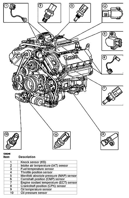
1 2005 Jaguar S-Type (X200) V8-4.2L Vehicle > Powertrain Management > Computers and Control Systems > Description and Operation > Components ELECTRONIC ENGINE CONTROLS Electronic Engine Controls Vehicles with supercharger 1/8
2 2/8
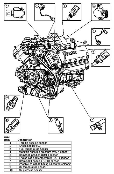
3 Vehicles without supercharger 3/8
4 4/8
5 ( ) Powertrain Control Module PCM The electronic engine control system consists of a powertrain control module (PCM), located behind the glove compartment, and a number of sensing and actuating devices. The sensors supply the PCM with input signals which relate to the engine operating conditions and driver requirements. The sensor information is evaluated by the PCM using the results to activate the appropriate response from the actuating devices. The system provides the necessary engine control accuracy and adaptability to: - Minimize exhaust emissions and fuel consumption. - Provide optimum driver control under all conditions. - Minimize evaporative emissions. 5/8
6 - Provide system diagnostics. In addition to these functions the PCM also interfaces with other vehicle systems through the controller area network (CAN). Camshaft Position ( CMP) Sensor The camshaft position (CMP) sensors monitor the position of both camshafts to allow the PCM to control the phase of the inlet camshafts relative to the position of the crankshaft. Variable Camshaft Timing Oil Control Solenoid The variable camshaft timing oil control solenoid is a hydraulic actuator, which advances and retards the inlet camshaft timing, thereby altering the camshaft to crankshaft phasing for optimum engine performance. Knock Sensors (KS) The knock sensors (KS) detect combustion knock within the engine cylinders and sends a signal to the PCM. The PCM uses this information to gradually adjust the ignition timing until the combustion knock is eliminated. Mass Air flow ( MAF) Sensor The mass air flow (MAF) sensor informs the PCM of the rate of air flow entering the engine by producing a voltage which is proportional to the rate of air flow into the engine. The voltage produced by the MAF sensor increases as the rate of air flow increases. The PCM takes into account the density of the air entering the air intake system so that it is possible to maintain the required air to fuel ratio, and to compensate for variations in atmospheric pressure. Integral to the MAF sensor is the intake air temperature sensor (IAT) which measures the temperature of the air entering the air intake system. The PCM uses this information to compensate for higher than normal air intake temperatures. Throttle Position (TP) Sensor The PCM monitors the angle of the throttle blade within the throttle housing through the throttle position (TP) sensor. The TP sends a voltage to the PCM which is proportional to the angle of the throttle plate. The voltage from the TP increases with the angle of the throttle plate. There are two sensor tracks within the TP sensor. Crankshaft Position ( CKP) Sensor The crankshaft position (CKP) sensor is an inductive pulse generator, which scans protrusions on a pulse ring fitted to the front of the crankshaft to inform the PCM of the crankshaft's position and speed. The CKP sensor produces an alternating voltage. The frequency of this voltage increases proportional to engine speed. Engine Coolant Temperature (ECT) Sensor The engine coolant temperature (ECT) sensor is a thermistor type sensor that provides an input signal to the PCM which is proportional to the engine coolant temperature. The ECT sensor is a negative temperature coefficient (NTC) sensor and its resistance decreases with a proportional increase in engine coolant 6/8
7 temperature. Oil Temperature Sensor The oil temperature sensor is a thermistor type sensor that provides an input signal to the PCM which is proportional to the engine oil temperature. Oil Pressure Switch The oil pressure switch is connected to the instrument cluster and is not directly part of the electronic engine control system. Heated Oxygen Sensor ( HO2S) The heated oxygen sensor (HO2S) is a linear characteristic type sensor, fitted forward of the exhaust system's catalytic converter. The PCM uses this as it's primary sensor to measure the oxygen content of the exhaust gasses within the exhaust system to provide closed-loop fuelling control. Catalyst Monitor Sensor The catalyst monitor sensor is a non-linear characteristic type sensor fitted to the exhaust system's catalytic converter. The PCM uses this as it's secondary sensor to measure the oxygen content of the exhaust gasses within the exhaust after they have passed through the catalytic converter. As well as providing additional closed-loop fuelling control the PCM uses this information to determine the efficiency of the catalytic converter. Intake Air Temperature (IAT) Sensor. Vehicles with supercharger. Vehicles with supercharger have an additional intake air temperature sensor located on the right-hand charge air cooler. The IAT measures the temperature of the air entering the charge air cooler. The PCM uses this information to compensate for higher than normal air intake temperatures. 7/8
8 8/8
E - THEORY/OPERATION - TURBO
 E - THEORY/OPERATION - TURBO 1995 Volvo 850 1995 ENGINE PERFORMANCE Volvo - Theory & Operation 850 - Turbo INTRODUCTION This article covers basic description and operation of engine performance-related
VOLKS CITY BEECH AVENUE CATTEDOWN PLYMOUTH PL4 0QQ
 VOLKS CITY BEECH AVENUE CATTEDOWN PLYMOUTH PL4 0QQ Telephone: 01752 667007 Fax: 01752 663399 Email: mail@volkscity.com 1 Camshaft position (CMP) sensor 1 2 Camshaft position (CMP) sensor 2 3 Camshaft position
Diagnostic Trouble Code (DTC) List - Vehicle
 List - Vehicle") Document ID# 850406 2002 Pontiac Firebird Diagnostic Trouble Code (DTC) List - Vehicle DTC DTC 021 and/or 031 DTC 022 and/or 032 DTC 023 or 033 DTC 24/34 DTC 025 and/or 035 DTC 041 DTC 042 DTC 043 DTC
Document ID# 850406 2002 Pontiac Firebird Diagnostic Trouble Code (DTC) List - Vehicle DTC DTC 021 and/or 031 DTC 022 and/or 032 DTC 023 or 033 DTC 24/34 DTC 025 and/or 035 DTC 041 DTC 042 DTC 043 DTC
 Page 1 of 6 2008 Ford Pickup 6.4L Eng F250 Super Duty ENGINE CONTROLS - DESCRIPTION AND OPERATION - F250-F550 SUPER DUTY 6.4L (DIESEL ) FUEL SYSTEM The fuel system includes the following: low pressure
Motronic September 1998
 The Motronic 1.8 engine management system was introduced with the 1992 Volvo 960. The primary difference between this Motronic system and the previous generation of Volvo LH-Jetronic engine management
Powertrain DTC Summaries EOBD
 Powertrain DTC Summaries Quick Reference Diagnostic Guide Jaguar S-TYPE V6, V8 N/A and V8 SC 2002.5 Model Year Refer to pages 2 9 for important information regarding the use of Powertrain DTC Summaries.
Powertrain DTC Summaries OBD II
 Powertrain DTC Summaries Quick Reference Diagnostic Guide Jaguar X-TYPE 2.5L and 3.0L 2002 Model Year Revised January, 2002: P0706, P0731, P0732, P0733, P0734, P0735, P0740, P1780 POSSIBLE CAUSES Revised
Powertrain DTC Summaries EOBD
 Powertrain DTC Summaries Quick Reference Diagnostic Guide Jaguar X-TYPE 2.0 L 2002.25 Model Year Refer to page 2 for important information regarding the use of Powertrain DTC Summaries. Jaguar X-TYPE 2.0
Powertrain DTC Summaries EOBD
 Powertrain DTC Summaries Quick Reference Diagnostic Guide Jaguar X-TYPE 2.5L and 3.0L 2001.5 Model Year Revised January, 2002: P0706, P0731, P0732, P0733, P0734, P0735, P0740, P1780 POSSIBLE CAUSES Revised
Telephone: Fax: VAT Registration No.:
 Telephone: Fax: VAT Registration No.: Name: Manufacturer: Ford Address: Model: Year: 1994 Registration: Tel - Private: Tel - Business: Mileage: Job number: Terminal side Wire side Component/circuit description
CONDITIONS FOR RUNNING THE DTC
 SYSTEM DESCRIPTION The powertrain control module (PCM) uses information from the crankshaft position (CKP) sensor and the camshaft position (CMP) sensor in order to determine when an engine misfire is
Transmission Electronic Control System
 SECTION 307-01: Automatic Transaxle/Transmission 5R55S 2009 Mustang Workshop Manual DESCRIPTION AND OPERATION Procedure revision date: 05/23/2008 Transmission Electronic Control System Electronic System
For Troubleshooting of DTC related components, see chart on page INTAKE AIR BYPASS (IAB) HIGH CONTROL SOLENOID
 HIGH CONTROL SOLENOID") Index For Troubleshooting of DTC related components, see chart on page 11-53. '96-99 models: EXHAUST GAS RECIRCULATION (EGR) and LIFT MANIFOLD ABSOLUTE PRESSURE (MAP) INTAKE AIR BYPASS (IAB) HIGH page
Index For Troubleshooting of DTC related components, see chart on page 11-53. '96-99 models: EXHAUST GAS RECIRCULATION (EGR) and LIFT MANIFOLD ABSOLUTE PRESSURE (MAP) INTAKE AIR BYPASS (IAB) HIGH page
Diagnostic Trouble Code (DTC) table
 table") Page 1 of 40 01-19 Diagnostic Trouble Code (DTC) table Note: When malfunctions occur in monitored sensors or components, Diagnostic Trouble Codes (DTCs) are stored in DTC memory with a description of the
Page 1 of 40 01-19 Diagnostic Trouble Code (DTC) table Note: When malfunctions occur in monitored sensors or components, Diagnostic Trouble Codes (DTCs) are stored in DTC memory with a description of the
 Verified Fix #1 Tool Data Diagnostic Trouble Code Information Report Customer #1 VIN: JT8BL69SX4G015327 Customer Name: Year: 2004 Customer Phone#: 123-123-1234 Make: Lexus Report#: 162 Model: GS 430 Date
Auto Diagnosis Test #7 Review
 Auto Diagnosis Test #7 Review Your own hand written notes may be used for the 1 st 10 minutes of the test Based on Chapters 25, 26, 32, 33, 34 and Lab Demonstrations Auto Diagnosis Test #7 Review Your
Fig.11 Powertrain Control Module (PCM)
") 2003 Dodge or Ram Truck Caravan V6-3.3L VIN R Vehicle > Powertrain Management > Relays and Modules - Powertrain Management > Relays and Modules - Computers and Control Systems > Engine Control Module >
2003 Dodge or Ram Truck Caravan V6-3.3L VIN R Vehicle > Powertrain Management > Relays and Modules - Powertrain Management > Relays and Modules - Computers and Control Systems > Engine Control Module >
Service Bulletin. DTC Detection Item Associated Monitor
 Service Bulletin 03-010 Applies To: All OBD II equipped models except SLX March 29, 2003 OBD II DTCs and Their Associated Monitors This is a list of all DTCs for all OBD II models. No one model has all
C6 Corvette DIC Codes
 C6 Corvette DIC Codes B0159 Outside Air Temp Sensor B2910 Steering Column Lock Password Incorrect B0164 Pass Compartment Temp Sensor B2981 Right Front Door Handle Switch B0174 Output Air Temp Sensor 1
Diagnostic Trouble Code (DTC) memory, checking and erasing
 memory, checking and erasing") Page 1 of 49 01-12 Diagnostic Trouble Code (DTC) memory, checking and erasing Check DTC Memory (function 02) - Connect VAS5051 tester Page 01-7 and select vehicle system "01 - Engine electronics". Engine
Page 1 of 49 01-12 Diagnostic Trouble Code (DTC) memory, checking and erasing Check DTC Memory (function 02) - Connect VAS5051 tester Page 01-7 and select vehicle system "01 - Engine electronics". Engine
Telephone: Fax: VAT Registration No.:
 Telephone: Fax: VAT Registration No.: Terminal side Wire side Component/circuit description ECM pin Signal Condition Typical value Oscilloscope setting (Suggested settings - Voltage/time per division)
Zoom and Print Options
 Vehicle» Engine, Cooling and Exhaust» Engine» Service and Repair» Removal and Replacement» Engine Replacement Engine Replacement ^ Tools Required - J 38185 Hose Clamp Pliers Removal Procedure 1. Remove
Fuel control. The fuel injection system tasks. Starting fuel pump (FP)
") 1 Fuel control The fuel injection system tasks - To provide fuel - To distribute the fuel between the cylinders - To provide the correct quantity of fuel Starting fuel pump (FP) The control module (1)
1 Fuel control The fuel injection system tasks - To provide fuel - To distribute the fuel between the cylinders - To provide the correct quantity of fuel Starting fuel pump (FP) The control module (1)
2002 ENGINE PERFORMANCE. Self-Diagnostics - RAV4. Before performing testing procedures, check for any related Technical Service Bulletins (TSBs).
.") 2002 ENGINE PERFORMANCE Self-Diagnostics - RAV4 INTRODUCTION NOTE: Before performing testing procedures, check for any related Technical Service Bulletins (TSBs). To properly diagnosis and repair this
2002 ENGINE PERFORMANCE Self-Diagnostics - RAV4 INTRODUCTION NOTE: Before performing testing procedures, check for any related Technical Service Bulletins (TSBs). To properly diagnosis and repair this
DTC P1415 Secondary Air Injection (AIR) System Bank 1
 System Bank 1") Page 1 of 5 2000 GMC Truck GMC K Sierra - 4WD Sierra, Silverado, Suburban, Tahoe, Yukon (VIN C/K) Service Manual Document ID: 546887 DTC P1415 Secondary Air Injection (AIR) System Bank 1 Circuit Description
Page 1 of 5 2000 GMC Truck GMC K Sierra - 4WD Sierra, Silverado, Suburban, Tahoe, Yukon (VIN C/K) Service Manual Document ID: 546887 DTC P1415 Secondary Air Injection (AIR) System Bank 1 Circuit Description
 http://www.prodemand.com/print/index?content=tabs&module=true&tab=true&terms=t... Page of // 0 Chevrolet Traverse.L Eng LT Service Manual: WIRING DIAGRAMS Print Date: // ENGINE PERFORMANCE >.L VIN D Fig
ATASA 5 th. Detailed Diagnosis & Sensors. Please Read The Summary
 ATASA 5 TH Study Guide Chapter 26 Pages 764 809 51 Points Please Read The Summary 1. Many different sensors are involved in the overall driveability of a vehicle. Input Processing Output Electronic Engine
Engine Cranks But Does Not Run
 Page 1 of 5 2000 GMC Truck GMC K Sierra - 4WD Sierra, Silverado, Suburban, Tahoe, Yukon (VIN C/K) Service Manual Engine Engine Controls - 4.8L, 5.3L, and 6.0L Diagnostic Information and Procedures Engine
5. Control System CONTROL SYSTEM FUEL INJECTION (FUEL SYSTEM) A: GENERAL FU(H4DOTC)-29
 A: GENERAL FU(H4DOTC)-29") W1860BE.book Page 29 Tuesday, January 28, 2003 11:01 PM 5. Control System A: GENERAL The ECM receives signals from various sensors, switches, and other control modules. Using these signals, it determines
W1860BE.book Page 29 Tuesday, January 28, 2003 11:01 PM 5. Control System A: GENERAL The ECM receives signals from various sensors, switches, and other control modules. Using these signals, it determines
5. Control System CONTROL SYSTEM FUEL INJECTION (FUEL SYSTEM) A: GENERAL. FU(STi)-27
 A: GENERAL. FU(STi)-27") W1860BE.book Page 27 Tuesday, January 28, 2003 11:01 PM 5. Control System A: GENERAL The ECM receives signals from various sensors, switches, and other control modules. Using these signals, it determines
W1860BE.book Page 27 Tuesday, January 28, 2003 11:01 PM 5. Control System A: GENERAL The ECM receives signals from various sensors, switches, and other control modules. Using these signals, it determines
Electronics III Sensors
 Electronics III Sensors Matthew Whitten Brookhaven College Sensor Defined. A device that responds to a stimulus, such as heat, light, or pressure, and generates a signal that can be measured or interpreted.
Fuel Metering System Component Description
 1999 Chevrolet/Geo Tahoe - 4WD Fuel Metering System Component Description Purpose The function of the fuel metering system is to deliver the correct amount of fuel to the engine under all operating conditions.
ProECU Subaru BRZ Toyota GT86 Scion FR-S
 ProECU Subaru BRZ Toyota GT86 Scion FR-S DTC List 2012-onward Model Year v1.0 Engine DTC List P000A Camshaft Position "A" - Timing Slow Response Bank 1 P000B Camshaft Position "B" - Timing Slow Response
9.6 ME-SFI (ME1.0) Engine 120
 Engine 120") Components on engine Model 129 Figure 1 B2/6 Left hot film MAF sensor (located on right side of engine) B2/7 Right hot film MAF sensor (located on left side of engine) B17/5 Left IAT sensor (located in
Components on engine Model 129 Figure 1 B2/6 Left hot film MAF sensor (located on right side of engine) B2/7 Right hot film MAF sensor (located on left side of engine) B17/5 Left IAT sensor (located in
01 02B ON-BOARD DIAGNOSTIC [ENGINE CONTROL SYSTEM (FS)]
![01 02B ON-BOARD DIAGNOSTIC [ENGINE CONTROL SYSTEM (FS)]](/thumbs/80/80600627.jpg "01 02B ON-BOARD DIAGNOSTIC [ENGINE CONTROL SYSTEM (FS)]") ON-BOARD DIAGNOSTIC [ENGINE CONTROL SYSTEM (FS)] CONTROL SYSTEM WIRING DIAGRAM [FS]............................ 2 CONTROL SYSTEM DEVICE AND CONTROL RELATIONSHIP CHART [FS]........ 4 Engine Control System............
ON-BOARD DIAGNOSTIC [ENGINE CONTROL SYSTEM (FS)] CONTROL SYSTEM WIRING DIAGRAM [FS]............................ 2 CONTROL SYSTEM DEVICE AND CONTROL RELATIONSHIP CHART [FS]........ 4 Engine Control System............
E - THEORY/OPERATION ENGINE PERFORMANCE General Motors Corp. - Theory & Operation - 5.7L
 E - THEORY/OPERATION 1998 ENGINE PERFORMANCE General Motors Corp. - Theory & Operation - 5.7L INTRODUCTION This article covers basic description and operation of engine performance-related systems and
DTC Summaries. NipponDenso V12 Engine Management
 DTC Summaries NipponDenso V12 Engine Management OBD II MONITORING CONDITIONS: When testing for DTC reoccurrence, it can be determined if the Service Drive Cycle was of sufficient length by performing a
Electronics III Sensors
 Electronics III Sensors Matthew Whitten Brookhaven College Sensor Defined. A device that responds to a stimulus, such as heat, light, or pressure, and generates a signal that can be measured or interpreted.
Cylinder Head Removal
 2006 Odyssey Cylinder Head Removal Report a problem with this article NOTE: Use fender covers to avoid damaging painted surfaces. To avoid damaging the wires and terminals, unplug the wiring connectors
DIAGNOSTIC TROUBLE CODE (DTC) DEFINITIONS
 DEFINITIONS") DIAGNOSTIC TROUBLE CODE (DTC) DEFINITIONS NOTE: Use the following table to identify the DTC and find the correct test step for the type of DTC retrieved. DIAGNOSTIC TROUBLE CODE (DTC) DEFINITION Diagnostic
DIAGNOSTIC TROUBLE CODE (DTC) DEFINITIONS NOTE: Use the following table to identify the DTC and find the correct test step for the type of DTC retrieved. DIAGNOSTIC TROUBLE CODE (DTC) DEFINITION Diagnostic
7. Remove the starter motor. Refer to Starter Motor Replacement (2.2L) or Starter Motor Replacement (4.3L).
 or Starter Motor Replacement (4.3L).") 1 of 9 1/5/2013 6:40 PM Removal Procedure 1. Disconnect the battery negative cable. Refer to Battery Replacement. 2. Remove the hood. Refer to Hood Replacement. 3. If the vehicle is equipped with a manual
1 of 9 1/5/2013 6:40 PM Removal Procedure 1. Disconnect the battery negative cable. Refer to Battery Replacement. 2. Remove the hood. Refer to Hood Replacement. 3. If the vehicle is equipped with a manual
Diagnostic Trouble Code (DTC) Root Cause. for Omnitek ECM 64A/66A/88A. & Remedial Action
 Root Cause. for Omnitek ECM 64A/66A/88A. & Remedial Action") Diagnostic Trouble Code (DTC) Root Cause & Remedial Action for Omnitek ECM 64A/66A/88A Omnitek Engineering Corp. 1945 S Rancho Santa Fe Rd. San Marcos, CA 92078 Tel. 760-591-0089 - Fax. 760-591-0880 -
Diagnostic Trouble Code (DTC) Root Cause & Remedial Action for Omnitek ECM 64A/66A/88A Omnitek Engineering Corp. 1945 S Rancho Santa Fe Rd. San Marcos, CA 92078 Tel. 760-591-0089 - Fax. 760-591-0880 -
2002 Buick Rendezvous - AWD
 2002 Buick Rendezvous - AWD DTC P0410 Description The control module activates the secondary air injection (AIR) system by grounding both the pump relay and the vacuum control solenoid control circuits.
Short to Ground High Resistance Open P0132, P0131, P0132, P0133, P0134, P0131, P0132, P0133, P0134, P0137, P0140, P0151, P0152,
 Page 1 of 7 2008 Pontiac G8 DTC P0140,, P2270, or P2271 Diagnostic Instructions Perform the Diagnostic System Check - Vehicle prior to using this diagnostic procedure. Review Strategy Based Diagnosis for
ENGINE 01 02A 1. Toc of SCT ON-BOARD DIAGNOSTIC [ENGINE. Toc of SCT 01 02A ON-BOARD DIAGNOSTIC [ENGINE CONTROL SYSTEM (ZM)] 01 02A
![ENGINE 01 02A 1. Toc of SCT ON-BOARD DIAGNOSTIC [ENGINE. Toc of SCT 01 02A ON-BOARD DIAGNOSTIC [ENGINE CONTROL SYSTEM (ZM)] 01 02A](/thumbs/90/103285807.jpg "ENGINE 01 02A 1. Toc of SCT ON-BOARD DIAGNOSTIC [ENGINE. Toc of SCT 01 02A ON-BOARD DIAGNOSTIC [ENGINE CONTROL SYSTEM (ZM)] 01 02A") ENGINE 01 SECTION Toc of SCT ON-BOARD DIAGNOSTIC [ENGINE CONTROL SYSTEM (ZM)]...01-02A ON-BOARD DIAGNOSTIC [ENGINE CONTROL SYSTEM (FS)]...01-02B ON-BOARD DIAGNOSTIC [CRUISE CONTROL SYSTEM].......01-02C
ENGINE 01 SECTION Toc of SCT ON-BOARD DIAGNOSTIC [ENGINE CONTROL SYSTEM (ZM)]...01-02A ON-BOARD DIAGNOSTIC [ENGINE CONTROL SYSTEM (FS)]...01-02B ON-BOARD DIAGNOSTIC [CRUISE CONTROL SYSTEM].......01-02C
DIAGNOSTIC TROUBLE CODE CHART
 DIAGNOSTIC TROUBLE CODE CHART 05 35 HINT: As for the vehicle for MEXICO, refer to Repair Manual 2003 COROLLA MATRIX (Pub. No. RM940U). Parameters listed in the chart may not be exactly the same as your
C5 Computer Diagnostic Codes
 C5 Computer Diagnostic Codes The ability to view engine operating data such as oil pressure and coolant temperature, in digital form on the instrument panel has been a feature of Corvettes since 1984.
1. Connect the Honda PGM Tester or an OBD II scan tool to the 16P Data Link Connector (DLC) located behind the right side of the center console.
 located behind the right side of the center console.") Troubleshooting Procedures I. How To Begin Troubleshooting When the Malfunction indicator Lamp (MIL) has been reported on, or there is a driveability problem, use the appropriate procedure below to diagnose
Troubleshooting Procedures I. How To Begin Troubleshooting When the Malfunction indicator Lamp (MIL) has been reported on, or there is a driveability problem, use the appropriate procedure below to diagnose
Lotus Service Notes Section EMR
 ENGINE MANAGEMENT SECTION EMR Lotus Techcentre Sub-Section Page Diagnostic Trouble Code List EMR.1 3 Component Function EMR.2 7 Component Location EMR.3 9 Diagnostic Guide EMR.4 11 CAN Bus Diagnostics;
2012 Chevy Truck Equinox FWD L4-2.4L Vehicle > Locations > Components
 2012 Chevy Truck Equinox FWD L4-2.4L Vehicle > Locations > Components 2012 Chevy Truck Equinox FWD L4-2.4L Vehicle > Powertrain Management > Fuel Delivery and Air Induction > Description and Operation
DTC P0420 or P0430. Circuit Description. DTC Descriptors. Conditions for Running the DTC
 Page 1 of 5 2005 Cadillac STS STS (VIN D) Service Manual Engine Engine Controls - 4.6L (LH2) Diagnostic Information and Procedures DTC P0420 or P0430 Circuit Description A three-way catalytic converter
1998 ENGINE PERFORMANCE. General Motors Corp. - Basic Diagnostic Procedures - 5.7L
 INTRODUCTION 1998 ENGINE PERFORMANCE General Motors Corp. - Basic Diagnostic Procedures - 5.7L The following diagnostic steps will help prevent overlooking a simple problem. This is also where to begin
Ignition control. The ignition system tasks. How is the ignition coil charge time and the ignition setting regulated?
 1 Ignition control The ignition system tasks To transform the system voltage (approximately 14 V) to a sufficiently high ignition voltage. In electronic systems this is normally above 30 kv (30 000 V).
2009 PCED Gasoline Engines SECTION 1: Description and Operation. Intake Air System
 2009 PCED Gasoline Engines SECTION 1: Description and Operation Procedure revision date: 05/27/2010 Overview Intake Air Systems The intake air system provides clean air to the engine, optimizes air flow,
Troubleshooting Self-diagnostic Procedures
 Self-diagnostic Procedures I. When the Malfunction Indicator Lamp (MIL) has been reported on, do the following: 1. Connect the Service Check Connector terminals with a jumper wire as shown. (The 2P Service
OBD-II Diagnostic Powertrain (P) Trouble Codes
 Trouble Codes") OBD-II Diagnostic Powertrain (P) Trouble Codes Please use our new & improved search engine to find information on your trouble codes. Search Now! This list contains standard diagnostic trouble codes (DTC
OBD-II Diagnostic Powertrain (P) Trouble Codes Please use our new & improved search engine to find information on your trouble codes. Search Now! This list contains standard diagnostic trouble codes (DTC
Cylinder Head Replacement
 CYLINDER HEAD REPLACEMENT (EN... CYLINDER HEAD REPLACEMENT (ENGINE MECHANICAL - 1.6L) Document ID# 1430093 Cylinder Head Replacement Tools Required J 45059 Angle Meter KM-470-B Angular Torque Gauge J 42492-A
JACKAROO TIPS Understanding the MIL fault codes on a Jackaroo Turbo Diesel
 JACKAROO TIPS Understanding the MIL fault codes on a Jackaroo Turbo Diesel The Jackaroo, as with all vehicles intended to be supplied to the USA market, (as the Isuzu Trooper) is fitted with OnBoard Diagnostics
Lotus Service Notes Section EMD
 ENGINE MANAGEMENT SECTION EMD Lotus Techcentre Sub-Section Page Diagnostic Trouble Code List EMD.1 3 Component Function EMD.2 8 Component Location EMD.3 10 Diagnostic Guide EMD.4 11 CAN Bus Diagnostics;
C5 Corvette IPC Diagnostic Display Mode
 C5 Corvette IPC Diagnostic Display Mode The IPC display, the 20-character, vacuum florescent screen above the steering column that says "Corvette by Chevrolet" every time you turn on the key is a powerful
I - SYSTEM/COMPONENT TESTS - TURBO
 I - SYSTEM/COMPONENT TESTS - TURBO 1995 Volvo 850 1995 ENGINE PERFORMANCE Volvo - System & Component Testing 850 - Turbo INTRODUCTION In this article, Engine Control Module (ECM) may also be referred to
Electronic Engine Controls
 Page 1 of 28 Published : Oct 22, 2004 Electronic Engine Controls 4.0 Liter Electronic Engine Controls Component Location Sheet 1 of 2 Item Part Number Description 1 - Mass air flow/ inlet air temperature
2001 Lincoln LS V6-3.0L DOHC VIN S Vehicle > Powertrain Management > Diagrams > Electrical - Interactive Color (Non OE) Engine Controls - Page 1 of 4
 Engine Controls - Page 1 of 4") /0/0 Engine Controls (Powertrain Management) - ALLDATA 00 Lincoln LS V-.0L DOHC VIN S Vehicle > Powertrain Management > Diagrams > Electrical - Interactive Color (Non OE) Engine Controls - Page of https://my.alldata.com/repair/#/repair/article//component//itype//nonstandard/0
/0/0 Engine Controls (Powertrain Management) - ALLDATA 00 Lincoln LS V-.0L DOHC VIN S Vehicle > Powertrain Management > Diagrams > Electrical - Interactive Color (Non OE) Engine Controls - Page of https://my.alldata.com/repair/#/repair/article//component//itype//nonstandard/0
P0030, P0036, -- P0135, P0141, P0155, P0161 P0030, P0036, P0050, P0056, P0135, P0141,
 Page 1 of 6 2008 Pontiac G8 DTC P0030, P0036, P0053, P0054, P0135, or P0141 Diagnostic Instructions Perform the Diagnostic System Check - Vehicle prior to using this diagnostic procedure. Review Strategy
PGM-FI ( Models)
") PGM-FI ( 00-0 Models) HOT AT ALL TIMES HOT IN ON OR START FUSE BACK UP, (RADIO).5A FUSE FI E/M 5A C PHOTO UNDER- HOOD FUSE/ RELAY PHOTO FUSE FUEL PUMP (SRS UNIT) 5A page 0-. UNDER- DASH FUSE/ RELAY PHOTO
PGM-FI ( 00-0 Models) HOT AT ALL TIMES HOT IN ON OR START FUSE BACK UP, (RADIO).5A FUSE FI E/M 5A C PHOTO UNDER- HOOD FUSE/ RELAY PHOTO FUSE FUEL PUMP (SRS UNIT) 5A page 0-. UNDER- DASH FUSE/ RELAY PHOTO
1996 Mustang. 1. Remove air cleaner outlet tube (9B659). Refer to Section Disconnect battery ground cable (14301). Refer to Section
. Refer to Section Disconnect battery ground cable (14301). Refer to Section") REMOVAL AND INSTALLATION Fuel Charging Wiring Removal and Installation 1. Remove air cleaner outlet tube (9B659). Refer to Section 03-12. 2. Disconnect battery ground cable (14301). Refer to Section 14-01.
REMOVAL AND INSTALLATION Fuel Charging Wiring Removal and Installation 1. Remove air cleaner outlet tube (9B659). Refer to Section 03-12. 2. Disconnect battery ground cable (14301). Refer to Section 14-01.
SYTY Trouble Code: ALDL INFORMATION
 SYTY Trouble Code: ALDL INFORMATION A -- Ground G -- Fuel Pump B -- Diagnostic Terminal H -- Brake Sense Speed Input F -- TCC M -- Serial Data (special tool needed - Do Not Use) For ECM Trouble Codes,
Engine management/transmission
 MAZDA Model: 323 (BG) 323 Estate 1,6/4x4 (BW) 323 (BA/BJ) 626/MX-6 626/Estate Xedos 6/9 MX-3/MX-5 Year: 1989-00 Engina code: BP, BP-DOHC, B3, B3E, B6, B6-SOHC, B6-DOHC, B6E,FP, FS, KF, KJ, KL K8, RF, RF-CX,
Lotus Service Notes Section EMQ
 ENGINE MANAGEMENT SECTION EMQ Lotus Techcentre Sub-Section Page Cylinder Numbering 2 Component Function EMQ.1 3 Component Location EMQ.2 5 Diagnostic Trouble Code List EMQ.3 7 Diagnostic Guide EMQ.4 11
Installation location The DME control unit is located in the electronics box on the bulkhead (illustration shows E65).
.") DME control unit: N62TU meeknet.co.uk/e64 Installation location The DME control unit is located in the electronics box on the bulkhead (illustration shows E65). Item Description Item Description 1 Electronics
DME control unit: N62TU meeknet.co.uk/e64 Installation location The DME control unit is located in the electronics box on the bulkhead (illustration shows E65). Item Description Item Description 1 Electronics
2-17 CABLE/HARNESS ROUTING SERVICE INFORMATION 1 IAC VALVE 2P CONNECTOR. 11 No.1 INJECTOR 2 TP SENSOR 3P CONNECTOR 2P CONNECTOR
 CABLE/ ROUTING SERVICE INFORMATION 11 No.1 INJECTOR 2P 15 IAB CONTROL SOLENOID VALVE 2P 1 IAC VALVE 2P 2 TP SENSOR 3P JUNCTION (24P) MAIN WIRE to SWITCH WIRE 6P 16 CMP SENSOR 1 CMP SENSOR 2 4P 14 EBT SENSOR
Component Locations. Index. D16Y5 engine: Note: For troubleshooting of DTC related components see chart on page THROTTLE POSITION (TP) SENSOR
 SENSOR") Index Note: For troubleshooting of DTC related components see chart on page 11-97. D16Y5 engine: THROTTLE POSITION (TP) MANIFOLD ABSOLUTE PRESSURE (MAP) EXHAUST GAS RECIRCULATION (EGR) VALVE and EXHAUST
Index Note: For troubleshooting of DTC related components see chart on page 11-97. D16Y5 engine: THROTTLE POSITION (TP) MANIFOLD ABSOLUTE PRESSURE (MAP) EXHAUST GAS RECIRCULATION (EGR) VALVE and EXHAUST
Diagnostic Trouble Codes (continued) GM Specific Codes
 GM Specific Codes") 85 GM Specific Codes P11XX Fuel and Air Metering P1106 MAP Sensor Circuit Intermittent High Voltage P1107 MAP Sensor Circuit Intermittent Low Voltage P1108 BARO to MAP Signal Comparison Too High P1111
85 GM Specific Codes P11XX Fuel and Air Metering P1106 MAP Sensor Circuit Intermittent High Voltage P1107 MAP Sensor Circuit Intermittent Low Voltage P1108 BARO to MAP Signal Comparison Too High P1111
cylinder cars / trucks (except Saturn S-series cars) ENGINE DIAGNOSTIC PARAMETERS
 ENGINE DIAGNOSTIC PARAMETERS") 2001 4-cylinder cars / trucks (except Saturn S-series cars) ENGINE DIAGNOSTIC S SECONDARY S AND Manifold Pressure/Throttle Position Sensor Manifold Pressure/Throttle Position Sensor Manifold Pressure Too
2001 4-cylinder cars / trucks (except Saturn S-series cars) ENGINE DIAGNOSTIC S SECONDARY S AND Manifold Pressure/Throttle Position Sensor Manifold Pressure/Throttle Position Sensor Manifold Pressure Too
Lotus Service Notes Section EMQ
 ENGINE MANAGEMENT SECTION EMQ Lotus Techcentre Sub-Section Page Component Function EMQ.1 3 Component Location EMQ.2 5 Diagnostic Trouble Code List EMQ.3 7 Diagnostic Guide EMQ.4 11 CAN Bus Diagnostics;
ARTICLE BEGINNING INTRODUCTION SELF-DIAGNOSTIC SYSTEM RETRIEVING DTCS ENGINE PERFORMANCE Volkswagen Self-Diagnostics - Gasoline
 Article Text ARTICLE BEGINNING 1996 ENGINE PERFORMANCE Volkswagen Self-Diagnostics - Gasoline Cabrio, Golf III, GTI, Jetta III, Passat INTRODUCTION If no faults were found while performing preliminary
MULTIPOINT FUEL INJECTION (MPI) <4G63-Turbo>
 <4G63-Turbo>") 13B-1 GROUP 13B MULTIPOINT FUEL INJECTI (MPI) CTENTS GENERAL INFORMATI........ 13B-2 SENSOR....................... 13B-8 THROTTLE VALVE OPENING ANGLE CTROL.............. 13B-9 FUEL INJECTI
13B-1 GROUP 13B MULTIPOINT FUEL INJECTI (MPI) CTENTS GENERAL INFORMATI........ 13B-2 SENSOR....................... 13B-8 THROTTLE VALVE OPENING ANGLE CTROL.............. 13B-9 FUEL INJECTI
MULTIPORT FUEL SYSTEM (MFI) <2.4L ENGINE>
 <2.4L ENGINE>") 13B-1 GROUP 13B MULTIPORT FUEL SYSTEM (MFI) CONTENTS GENERAL DESCRIPTION 13B-2 CONTROL UNIT 13B-5 SENSOR 13B-7 ACTUATOR 13B-24 FUEL INJECTION CONTROL 13B-31 IGNITION TIMING AND CONTROL FOR
13B-1 GROUP 13B MULTIPORT FUEL SYSTEM (MFI) CONTENTS GENERAL DESCRIPTION 13B-2 CONTROL UNIT 13B-5 SENSOR 13B-7 ACTUATOR 13B-24 FUEL INJECTION CONTROL 13B-31 IGNITION TIMING AND CONTROL FOR
SECTION 03-04A Fuel Charging and Controls- 1.6L
 3-4A- 1 Chargins and Controls- 1.6L 3-4A-1 SECTION 3-4A Charging and Controls- 1.6L SUBJECT PAGE SUBJECT PAGE ADJUSTMENTS Idle Speed... 3-4A-16 Throttle Posltlon (TP) Sensor... 3-4A-16 DESCRIPTION AND
SECONDARY PARAMETERS AND ENABLE CONDITIONS
 SECONDARY S AND Manifold Pressure Sensor Rationality Manifold Pressure Too Low Manifold Pressure Too High Intake Air Temperature Sensor Shorted Intake Air Temperature Sensor Open Coolant Temperature Sensor
 http://www.prodemand.com/print/index?content=tabs&module=true&tab=true&terms=tr... Page of //0 00 Chevrolet Silverado.L Eng 00 Service Manual: WIRING DIAGRAMS - 00 Print Date: //0 ENGINE PERFORMANCE Tip:
Diagnostic Trouble Codes (continued) SAE Defined Codes
 SAE Defined Codes") 78 SAE Defined Codes P01XX Fuel and Air Metering P0100 Mass or Volume Airflow Circuit Problem P0101 Mass or Volume Airflow Circuit Range or Performance Problem P0102 Mass or Volume Airflow Circuit Low
78 SAE Defined Codes P01XX Fuel and Air Metering P0100 Mass or Volume Airflow Circuit Problem P0101 Mass or Volume Airflow Circuit Range or Performance Problem P0102 Mass or Volume Airflow Circuit Low
MULTIPORT FUEL SYSTEM (MFI)
") 13A-1 GROUP 13A CONTENTS GENERAL INFORMATION...13A-2 CONTROL UNIT...13A-7 SENSOR...13A-9 ACTUATOR...13A-26 FUEL INJECTION CONTROL...13A-31 IGNITION TIMING AND CONTROL FOR CURRENT CARRYING TIME...13A-36
13A-1 GROUP 13A CONTENTS GENERAL INFORMATION...13A-2 CONTROL UNIT...13A-7 SENSOR...13A-9 ACTUATOR...13A-26 FUEL INJECTION CONTROL...13A-31 IGNITION TIMING AND CONTROL FOR CURRENT CARRYING TIME...13A-36
Engine Control Components
 2009 PCED Gasoline Engines SECTION 1: Description and Operation Procedure revision date: 05/27/2010 Engine Control Components Note: Transmission inputs which are not described in this section, are discussed
Kubota Engine Training: WG1605, spark ignited
 Kubota Engine Training: WG1605, spark ignited WG1605 Engine Training: System Overviews Mechanical Components Electronic Components and Sensors Operation Service Tool Fuel System Overview: Fuel System Overview:
EMISSION CONTROL (AUX. EMISSION CONTROL DEVICES) H4SO
 H4SO") EMISSION CONTROL (AUX. EMISSION CONTROL DEVICES) H4SO SYSTEM OVERVIEW 1. System Overview There are three emission control systems, which are as follows: Crankcase emission control system Exhaust emission
EMISSION CONTROL (AUX. EMISSION CONTROL DEVICES) H4SO SYSTEM OVERVIEW 1. System Overview There are three emission control systems, which are as follows: Crankcase emission control system Exhaust emission
DTC P0174 Fuel Trim System Lean Bank 2
 2000 Chevrolet/Geo S10 Pickup - 4WD DTC P0174 Fuel Trim System Lean Bank 2 Circuit Description In order to provide the best possible combination of driveability, fuel economy, and emission control, the
Lower Intake Manifold Replacement
 Lower Intake Manifold Replacement Removal Procedure 1. Turn OFF all the lamps and the accessories. 2. Ensure the ignition switch is in the OFF position. 3. Disconnect the negative battery cable from the
1.2 HFM Sequential Multiport Fuel Injection/Ignition System (HFM-SFI) Engine 111
 Engine 111") Diagnosis - Diagnostic Trouble Code () Memory Preliminary work:........................ Engine Test, djustment, Engines, Volume 1 Note regarding diagnostic trouble code () readout: The engine control module
Diagnosis - Diagnostic Trouble Code () Memory Preliminary work:........................ Engine Test, djustment, Engines, Volume 1 Note regarding diagnostic trouble code () readout: The engine control module
EMISSION CONTROL (AUX. EMISSION CONTROL DEVICES) H4DOTC
 H4DOTC") EMISSION CONTROL (AUX. EMISSION CONTROL DEVICES) H4DOTC SYSTEM OVERVIEW 1. System Overview There are three emission control systems, which are as follows: Crankcase emission control system Exhaust emission
EMISSION CONTROL (AUX. EMISSION CONTROL DEVICES) H4DOTC SYSTEM OVERVIEW 1. System Overview There are three emission control systems, which are as follows: Crankcase emission control system Exhaust emission
2. Turbocharger System
 INTAKE (INDUCTION) 2. Turbocharger System A: GENERAL The turbocharger system consists of a water-cooled turbocharger, air-cooled intercooler, wastegate control solenoid valve, etc. The turbine rotated
1995 Nissan Altima ECU
 by jserrano (www.nissanclub.com) 1995 Nissan Altima ECU Pin Color Name Symbol Description Signal Rev. 0.6 1 W Ignition Signal IGN This pulse signal drives the base of the ignition power transistor and
GM Enhanced Parameters
 GM Enhanced Parameters # of 4x Ref Pulses between CAM Counter # OF EGR ADAPTIVE LEARN MATRIX CELLS OUT OF RANGE High # OF EGR ADAPTIVE LEARN MATRIX CELLS OUT OF RANGE LOW 1-2 Adapt High Cell 1-2 Adapt
Powertrain Control Module Connector End Views
 Page 1 of 6 2005 GMC Truck Canyon Pickup - 4WD Canyon, Colorado (VIN S/T) Service Manual Engine Engine Controls - 3.5L (L52) Diagnostic Information and Procedures Powertrain Control Module Connector End
A L L Diagnostic Trouble Codes ( DTC ): P Code Charts General Information
: P Code Charts General Information") P0133 O2-Sensor Circuit Slow Response (Bank 1 / Sensor 1) - The linear O2 sensor is mounted on the front side of the Catalytic Converter (warm-up catalytic converter) or in the front exhaust pipe. It detects
P0133 O2-Sensor Circuit Slow Response (Bank 1 / Sensor 1) - The linear O2 sensor is mounted on the front side of the Catalytic Converter (warm-up catalytic converter) or in the front exhaust pipe. It detects
Diagnostic Trouble Code (DTC) Charts and Descriptions
 Charts and Descriptions") Page 1 of 126 2006 PCED On Board s SECTION 4: Powertrain DTC Charts and Descriptions Procedure revision date: 04/06/2006 Trouble Code (DTC) Charts and Descriptions Note: Refer to the applicable Workshop
Page 1 of 126 2006 PCED On Board s SECTION 4: Powertrain DTC Charts and Descriptions Procedure revision date: 04/06/2006 Trouble Code (DTC) Charts and Descriptions Note: Refer to the applicable Workshop
3/14/2018 Engine Controls (Powertrain Management) - ALLDATA
 - ALLDATA") //0 Engine Controls (Powertrain Management) - ALLDATA 00 Chrysler Truck PT Cruiser L-.L VIN X Vehicle > Powertrain Management > Diagrams > Electrical - Interactive Color (Non OE) Engine Controls - Page
//0 Engine Controls (Powertrain Management) - ALLDATA 00 Chrysler Truck PT Cruiser L-.L VIN X Vehicle > Powertrain Management > Diagrams > Electrical - Interactive Color (Non OE) Engine Controls - Page
OBD-Codes.com Your OBD-II Trouble Codes Repair Site
 Page 1 sur 11 OBD-Codes.com Your OBD-II Trouble Codes Repair Site URL of this page: Like 261 likes. Sign Up to see what your friends like. OBD-II (Check Engine Light) Trouble Codes Welcome to OBD-Codes.com,
2.8 Liter VR6 2V Fuel Injection & Ignition, Engine Code(s): AAA m.y
: AAA m.y") 2.8 Liter VR6 2V Fuel Injection & Ignition, Engine Code(s): AAA m.y. 1996-1997 01 - On Board Diagnostic (OBD) On Board Diagnostic (OBD II) Malfunction Indicator Lamp (MIL) On Board Diagnostic (OBD II),
2.8 Liter VR6 2V Fuel Injection & Ignition, Engine Code(s): AAA m.y. 1996-1997 01 - On Board Diagnostic (OBD) On Board Diagnostic (OBD II) Malfunction Indicator Lamp (MIL) On Board Diagnostic (OBD II),
EMISSION CONTROL (AUX. EMISSION CONTROL DEVICES) H6DO
 H6DO") EMISSION CONTROL (AUX. EMISSION CONTROL DEVICES) H6DO SYSTEM OVERVIEW 1. System Overview There are three emission control systems, which are as follows: Crankcase emission control system Exhaust emission
EMISSION CONTROL (AUX. EMISSION CONTROL DEVICES) H6DO SYSTEM OVERVIEW 1. System Overview There are three emission control systems, which are as follows: Crankcase emission control system Exhaust emission