For Installing Harness Number: Manual #90627
|
|
|
- Agatha Gaines
- 5 years ago
- Views:
Transcription


1 Wire Harness Installation Instructions For Installing Harness Number: 20205: 27 Circuit GM Truck Manual #90627 Painless Performance Products recommends you, the installer, read this installation manual from front to back before installing this harness.
2 Painless Performance Products, LLC 2501 Ludelle St. Fort Worth, TX PHONE: FAX: If you have any questions concerning the installation of this harness, feel free to call Painless Performance Products' Tech Line at The Tech Line can be reached from 8 A.M. to 5 P.M. central time, Monday through Thursday, and 8 A.M. to 4:30 P.M. on Fridays. We have attempted to provide you with as accurate of instructions as possible and are always concerned about corrections or improvements that can be made. If you have found any issues or omissions, or simply have comments or suggestions concerning these instructions, please write us at the above address, send us a fax at (817) , or us at painless@painlessperformance.com. We sincerely appreciate your business. Painless Performance Products, LLC shall in no event be liable in contract or tort (including negligence) for special, indirect, incidental, or consequential damages, such as but not limited to, loss of property damage, or any other damages, costs or expenses which might be claimed as the result of the use or failure of the goods sold hereby, except only the cost of repair or replacement. i
3 CAUTION: BEFORE THE REMOVAL OF YOUR ORIGINAL HARNESS AND/OR THE INSTALL OF YOUR NEW PAINLESS HARNESS, DISCONNECT THE POWER FROM YOUR VEHICLE BY REMOVING THE NEGATIVE OR POSITIVE BATTERY CABLE FROM THE BATTERY. A full-color copy of these instructions can be found online at: If your vehicle has an existing harness, you will want to retain it for the possible re-use of various pigtails and connector housings particular to your application. During the removal process, avoid making any unnecessary cuts. All portions of this harness, with the exception of the dash harness, are universal in nature. This means the ends are left open to allow you to cut each wire to length and install/make the appropriate connection. Parts packages and the bag kits with terminals and connectors included with the harness will enable you to make these connections. Painless offers other products, as outlined throughout this manual, which work well with this harness and that provide parts, wire, or sub-harness that this kit does not have. Only printed wires have a 900-series number. These 900-series numbers are used to identify various wires and circuits in the wiring diagrams that are a part of these instructions. In the event that there are unused or unconnected wires, they will need to have their ends terminated with an insulated terminal or electrical tape. Doing so will prevent the wires from shorting and causing harness failure or fire. ii
4 PAGE # iii SECTION TABLE OF CONTENTS 1 INTRODUCTION 2 CONTENTS 3 SMALL PARTS 4 TOOLS NEEDED 5 TO REMOVE A TERMINAL 6 INSTALLING FACTORY STYLE TERMINALS 7 GROUNDS 8 WHY ARE CLEAN GROUNDS IMPORTANT? 10 FUSE BLOCK 10 HORN RELAY 10 FLASHERS 11 FUSE IDENTIFICATION 12 ACCESSORY PORTS 13 RELAYS & SWITCHES 16 OLD FACTORY HARNESS REMOVAL 18 PRE-INSTALLATION GUIDELINES 18 FUSE BLOCK / INTERIOR HARNESS 20 ACCESSORY SECTION 21 ENGINE BULKHEAD 22 BULKHEAD PINOUT 24 FUSE BLOCK MOUNTING 24 ENGINE BULKHEAD MOUNTING 25 BEFORE ROUTING THE ENGINE HARNESS 26 HARNESS ROUTING 26 HEADLIGHT SECTION 27 ENGINE & TAIL SECTIONS 28 INTERIOR HARNESS 29 ENGINE HARNESS CONNECTIONS 29 WIPER MOTOR SECTION 29 WIPER MOTOR ( ) WASHER PUMP 33 FRONT LIGHTING SECTION 34 LIGHT CONFIGURATIONS 34 GROUNDS 36 LEFT / DRIVER SIDE HEADLIGHT 37 LEFT PARK / SIDE MARKER LIGHT 39 LEFT TURN / PARK LIGHT 40 DRIVER SIDE GROUND 40 BRAKE PRESSURE WARNING SWITCH 40 FAN RELAY/ACCESSORY 42 HORN(S) 43 RIGHT TURN / PARK LIGHT & HEADLIGHT 48 ENGINE SECTION CONNECTIONS 48 COOLANT TEMP SENSOR Continued
5 PAGE # SECTION TABLE OF CONTENTS 49 OIL PRESSURE SENSOR 50 ELECTRIC CHOKE 51 TURBO 400 / 700R4 TRANSMISSION 51 Turbo R4 53 COIL / IGNITION SECTION 54 TACHOMETER 57 START / CHARGE SECTION 57 ALTERNATOR 59 GM SI SERIES ALTERNATORS 60 GM CS-130 SERIES ALTERNATORS 62 GM CS-130D SERIES ALTERNATORS 64 MIDI FUSE 66 STARTER SOLENOID 66 4L60e/4L80e Switch 69 RECONNECTING FACTORY JUNCTION BLOCK 69 TAIL SECTION 69 FUEL SYSTEM 70 Non-EFI 70 EFI 71 Single Tank 71 Dual Tanks 72 Early Valve 72 Later Valve 76 Electrical Fuel Pump 78 OPTIONAL INLINE CONNECTION FOR TRUCKS (# Sold Separately) 79 TAILLIGHT WIRE 79 REVERSE LIGHT WIRE 80 LEFT SIDE ROUTING 80 LEFT SIDE MARKER LIGHT 81 LEFT TURN - BRAKE LIGHTS / TAILLIGHTS 81 REVERSE LIGHT 82 GROUND 83 LICENSE PLATE LIGHT 83 RIGHT TURN/ BRAKE/ REVERSE/ MARKER LIGHTS/ GROUNDS 87 INTERIOR HARNESS 87 DIMMER SWITCH 88 EMERGENCY BRAKE SWITCH 89 GROUNDS 90 LEFT/DRIVER DOOR JAMB SWITCH 92 A/C-HEAT 92 FACTORY HEATER OR A/C HARNESS 92 PAINLESS #30902 A/C HARNESS 93 HEATER ONLY SYSTEMS Continued iv
6 PAGE # SECTION TABLE OF CONTENTS 95 A/C-HEAT PANEL LIGHT 95 AFTERMARKET A/C 96 RADIO & ACCESSORIES 97 ACCESSORY SECTION 97 Cigarette Lighter / Power Port 97 Accessory Wires 98 Power a Component 99 Relays 101 Power Windows & Power Locks 102 RADIO 103 FUEL TANK SWITCH 105 COURTESY LIGHTS 105 PASSENGER SIDE DOOR JAMB SWITCH 107 HEADLIGHT SWITCH 109 WIPER SWITCH SWITCHES SWITCHES SWITCHES (COLUMN MOUNTED) 113 REVERSE SWITCH 114 NEUTRAL SAFETY / CLUTCH SWITCH 116 TURBO 400 THROTTLE SWITCH / 700R4 BRAKE SWITCH 116 TURBO R4 117 CRUISE CONTROL 118 IGNITION SWITCH 120 TURN SIGNAL SWITCH 122 BRAKE SWITCH PIN BRAKE SWITCH 125 INSTRUMENT PANEL 126 FACTORY PRINTED CIRCUIT GAUGES 131 4X4 INDICATOR 132 TACHOMETER 132 Aftermarket Tachometer 133 CLOCK 134 SEPARATE HARNESSES- PAINLESS #30301 & HARDWIRING 140 DOME LIGHT SECTION 140 SEAT BELT 141 DOME LIGHT 141 AFTERMARKET AMPLIFIER 142 TESTING THE SYSTEM 143 WIRE INDEX 150 WARRANTY & RETURN POLICY 152 BULKHEAD TEMPLATE v
7 SCHEMATICS PAGE # SECTION VOLT SOURCE ACTIVATION 14 GROUND ACTIVATION 14 FAN RELAY GROUND ACTIVATION 15 FORM C RELAY w/ DIODE WIPER SCHEMATIC 32 WIPER SCHEMATIC 39 FRONT SIDE MARKER LIGHT 41 ACC. RELAY ACTIVATION 41 ACC. RELAY ACTIVATION w/ SWITCH 42 DIRECT ACC. ACTIVATION 44 FRONT LIGHTING SECTION 45 FRONT LIGHTING w/ DUAL/QUAD HEADLIGHTS 46 FRONT LIGHTING GROUND 47 ENGINE SECTION 52 TH400 TRANSMISSION w/ ENGINE MOUNTED THROTTLE SWITCH 53 VACUUM SWITCH 55 COIL CONNECTIONS (NO BALLAST RESISTOR) 55 BALLAST RESISTOR CONNECTIONS 56 HEI COIL ON CAP CONNECTIONS 56 MSD IGNITION CONNECTIONS SI ALTERNATOR 61 CS-130 ALTERNATOR 63 CS-130D ALTERNATOR 67 EARLY 4L60e/4L80e NSS/REVERSE SWITCH 67 LATER 4L60e/4L80e NSS/REVERSE SWITCH 68 CHARGE / BATTERY POWER 73 LATER FUEL SELECTOR VALVE 74 EARLIER DUAL TANK 75 LATER STYLE DUAL TANK 75 LATER STYLE DUAL TANK EFI 77 TYPICAL FUEL PUMP RELAY 79 TAILLIGHT SPLICING & CHAINING 79 REVERSE LIGHT SPLICING/CHAINING 84 TAIL SECTION SCHEMATIC, SPLICING 85 TAIL SECTION SCHEMATIC, CHAINING 86 TAIL SECTION SCHEMATIC, COMBO 88 HEADLIGHT DIMMER SWITCH 89 GROUND SCHEMATIC 94 HEATER ONLY 94 HEATER ONLY, HD 96 A/C, RADIO, & ACCESSORY 98 INTERIOR ACCESSORY POWER 99 EXTERIOR ACCESSORY POWER 100 EXTERIOR ACC. RELAY ACTIVATION 100 INTERIOR ACC. RELAY ACTIVATION 101 ACC. RELAY ACTIVATION w/ SWITCH 104 FUEL TANK SWITCHES 106 DOME/COURTESY LIGHT & SEAT BELT 108 HEADLIGHT SWITCH & DIMMER SWITCH WIPER SWITCH Continued vi
8 PAGE # SECTION SCHEMATICS WIPER SWITCH WIPER SWITCH 119 IGNITION SWITCH 124 TURN SIGNAL SWITCH, BRAKE SWITCH, & THROTTLE SWITCH IND. LIGHT CLUSTER 128 CHARGE INDICATOR LIGHT GAUGE CLUSTER w/o TACH GAUGE CLUSTER w/ TACH GAUGE CLUSTER w/o TACH GAUGE CLUSTER w/ TACH GAUGE CLUSTER (ALL) 134 PAINLESS #30301 & #30302 CONNECTOR PINOUT 135 INSTRUMENT PANEL 136 POWERING AFTERMARKET GAUGES (SPLICING) 136 POWERING AFTERMARKET GAUGES (CHAINING/JUMPING) 137 GROUNDING AFTERMARKET GAUGES (SPLICING) 137 GROUNDING AFTERMARKET GAUGES (CHAINING/JUMPING) 138 AFTERMARKET GAUGE LIGHT POWER (SPLICING) 138 AFTERMARKET GAUGE LIGHT POWER (CHAINING/JUMPING) 139 AFTERMARKET GAUGE SENDER WIRES 152 BULKHEAD TEMPLATE FOR VEHICLES WITH NO BULKHEAD HOLE vii
9 ADDITIONAL PART # S 40140: Universal Body / Engine Ground Strap Kit 70920: PowerBraid Chassis Harness Kit 70970: ClassicBraid Chassis kit 30350: Socket Kit Single Round Headlights 30351: Socket Kit Single Square Headlights 30352: Socket Kit Dual Headlights 30353: Socket Kit Suburban/Jimmy 60109: TH700R4 Transmission Torque Converter Lock-Up Kit 30707: Delco CS Style Ext. Fan GM Alternator Pigtail 30705: CS 130D Style GM Alternator Pigtail 60101: GM 4.3L V6; 5.0, 5.7 & 7.4L V8 TBI Harness Std. Length 60201: GM 4.3L V6, 5.0, 5.7 & 7.4L V8 TBI Harness Extra Length 60508: GM LS1/LS6 EFI Harness 60217: GM Gen III 4.8/5.3/6.0L EFI Harness - Mechanical TB 70404: 4 Circuit Male & Female Weatherpack Kit 30902: A/C Harness 80176: Brake Light Switch, 4-Terminal 80172: Brake Light Switch/Push Button 60109: TH700R4 Transmission Torque Converter Lock-Up Kit 60110: 200-4R Transmission Torque Converter Lock-Up Kit 30301: Gauge Wiring Harness/Mechanical Speedometer 30302: Gauge Wiring Harness/Electric Speedometer viii
10 INTRODUCTION Thank you for your purchase of a Painless Performance Products Harness. This is a customizable harness; therefore, we suggest you retain your original harness for any unique plugs or connectors you may need while installing your new harness. The fuse block is pre-terminated, and the proper fuses for each circuit are preinstalled. All wires are colored based on GM color codes. Also, each wire is marked with a 900-series wire number, what section the wire is in, and the wire s function. These 900- series numbers are assigned by Painless and do not correspond to any circuit numbers found on any factory wiring schematics. A Wire Index is located on pages and provides a quick reference guide for the individual wires of this harness. The Wire Index identifies the gauge, color, what s printed on the wire, and point of origin for each wire. During the course of this manual, you will notice wires with a slash (Ex. BLUE/WHITE). This indicates a wire with a stripe. The first color listed is the main wire color, and the second color will reference the stripe color. Therefore, the BLUE/WHITE example will be a BLUE wire with a WHITE Stripe. Do not let the length of this instruction manual intimidate you. Much of the information contained in this manual is helpful information about each wire, where the wire comes from, where it goes, why a component needs it, etc. In many cases, there are multiple schematics as well as alternate connection options for the same wire/connection point due to this being a customizable harness. You will find that the actual install portions of this manual are pretty straightforward and easy to follow. Individual components and sections are tied together for easy routing of the harness. GM color coded wires with printed circuit numbers and descriptions on each, along with the schematic diagrams found throughout this manual, will help you identify the different circuits during installation and later on if additions to the overall system are necessary. 1
 423-9696.")
11 CONTENTS Refer to the Contents Picture (below) to take inventory of this kit. See that you have everything you re intended to have in this kit. If you find that anything is missing or damaged, please contact the dealer where you obtained the kit or Painless Performance at (800) The Painless Wire Harness Kits contains the following: Pre-terminated fuse block and interior harness. Bulkhead and engine harness. 2 Front Lighting Ground Sub harnesses (1) 6-gauge charge wire (2) Small Parts Kits (1) Heater Only bag Containing a sub harness, pigtails and 2 resistor connectors (4) Parts bags: Alternator bag, uninsulated terminal bag, heat shrink bag, and a larger miscellaneous parts bag that includes cable ties, connectors and other parts. 2


12 SMALL PARTS Included with the Painless harness are parts kits containing miscellaneous terminals, fuses, and screws. Many of the terminals are non-insulated and will require heat shrink to be applied after the terminal has been properly crimped. Heat shrink has been supplied. These non-insulated terminals allow you to keep a cleaner, more factory look; colored insulated terminals can look out of place. When crimping these terminals, take notice to the split in the terminal. Always make sure the split in these non-insulated terminals is facing the groove. Umbrella style cable tie clips have been provided for you to attach the Painless harness to the inner fender, core support, and/or frame. These cable tie clips fit into ¼ holes left behind by factory plastic retainer loops or those created with a drill by the installer. 3


13 TOOLS NEEDED In addition to your regular hand tools, you will need, at least, the following tools: Wire Crimping and Stripping Tools: The style of hand crimpers seen to the right are available at just about any local auto parts store, home improvement store, or can also be purchased online. You need this style of crimper to crimp many of the terminals included in the small parts kits. Another style of crimpers is Jaw Crimpers or Roll-Over Crimpers. These crimpers will crimp factory style, non-insulated terminals. These types of terminals are provided in the kit for connecting to an HEI distributor, headlights, and factory style alternator. Painless offers Roll-Over Crimpers, such as those seen to the right, under Painless part # A hammer crimper, seen to the right, will be useful for crimping ends onto large gauge wires. These crimpers will crimp large, non-insulated terminals, and can be purchased relatively cheaply from most auto parts stores and online. A good set of wire strippers is required to strip wire properly. This style of wire stripper is ideal for this harness install because of its ability to properly strip wire gauges 10 to 20. These are available from just about any local auto part store, electrical supply shop, home improvement store or can be purchased online. 4


14 Volt/Ohm Meter: A Volt/Ohm meter is always a good tool to have on hand when installing any type of electrical components in a vehicle. Most basic units provide the two functions required to diagnose electrical issues seen during a harness install. These two functions are the ability to read DC Voltage and electrical continuity or Ohms. They can be purchased from any home improvement store, local hardware store, electrical supply shop, and online. Electric Drill & Drill Bits: A drill and bits are needed in order to mount the MIDI fuse holder and the fuse block. Additionally, a ¼ drill bit is required in order to mount the umbrella style cable ties provided with the kit. Heat Gun: Very useful to shrink the heat-shrinkable terminals found in the parts kit. Small (10 amp or less) Battery Charger See TESTING THE SYSTEM located on page 142. Factory Wire Schematic This isn t absolutely necessary; however, having one handy is good practice with any electrical job. TO REMOVE A TERMINAL Notice the locking tang that holds the terminal in the connector. Locate the tang access slot on the terminal end of the connector. Push a paper clip, stiff wire, or a small flat head screwdriver into the slot to depress the locking tang on the terminal. Once depressed, pull the harness wire from the connector. Do not pull too hard or you could pull the wire out of the terminal; this leaves the terminal stuck in the connector. 5


15 INSTALLING FACTORY STYLE TERMINALS In the parts kit, you will see different uninsulated male and female terminals. These terminals are for factory style connections and require roll over crimpers. Strip about ¼ of insulation off of the wire. Insert the wire into the terminal. There are two terminal straps on the terminal. For instructional purposes, we will label them 1 and 2. Strap 1 crimps the exposed copper strands of the wire, while strap 2 crimps the wire insulation. Make your strip length long enough to ensure only copper strands are crimped by Strap 1 but short enough that only insulation is crimped by Strap 2. The photo to the left best demonstrates this. Using the appropriate jaw on the crimpers, crimp Strap 1. The appropriate jaw depends on the wire gauge as well as the terminal stiffness. If you are unsure which jaw to use, you can always start with the biggest and work your way down until you get a tight crimp. With Strap 1 crimped, move onto crimping the insulation strap: Strap 2. Place Strap 2 into the appropriate jaw of the crimpers. This jaw will be larger than the one used to crimp the first strap. Crimp down on Strap 2 making sure the strap folds down into the wire, and not overlapping itself. Refer to the drawing to the left. Overlapping could cause problems with the terminal fitting into the connector. 6


16 GROUNDS Throughout this instruction manual, and when looking at the Painless harness, you will see the word GROUND. Maybe you have seen the ground symbol on wiring diagrams before? What exactly is a ground and why do you need it? You have probably noticed the large cable coming from the negative side of your battery going down to the frame or to the engine. This cable allows voltage to get back to the battery through the metal of the frame and all the other metal pieces bolted to the frame. It is also important to have ground cables going from the frame to the engine and from the frame to the body, such as those in the Painless Universal Body / Engine Ground Strap Kit part #40140 seen to the left. A ground is simply the common path electrical current follows back to the battery. A ground, or chassis ground as it is often called, is any bare metal surface found on the vehicle which is in turn connected back to the frame/negative side of the battery through mounting points and ground straps. Grounds are needed in order for the electrical current to complete the circuit. There are two ways components are grounded in vehicles: through mounting and through a wired connection. Some grounds are supplied through mounting of the metal housings in which bulbs are installed, like turn signal or tail light housings. Components with plastic housings or non-conductive housings, like headlights which are glass, get their grounds through wires from the chassis harness. 7
17 Make sure all mounting points are clean by removing any dirt, corrosion, and/or paint. This includes light housings that ground through mounting them and the harness ground wire connection point. This is especially important for trucks that have recently been painted as paint build up will cause grounding issues. 80 grit or courser sandpaper should be all that s needed to properly clean grounding points. To help avoid grounding problems, this kit provides ground harnesses for the front and rear lighting sections. The front lighting ground harness covers the headlights, front turn signals, and park lights. The rear ground harness covers the tail lights, rear turn signals, marker lights, reverse lights, and license plate light. Three braided ground straps have also been supplied to allow grounding the body of the vehicle to the frame. Good locations for these straps are the core support to the frame, firewall/floorboard to the frame, and bed to the frame. Self-tapping screws and star washers have also been provided in the parts bag to make installation easier. WHY ARE CLEAN GROUNDS IMPORTANT? As an example, we will use a front turn signal that also functions as a park light. Follow the red line from right to left in the diagram below. This red line indicates the path the electrical current takes when everything is properly grounded. The diagram on the next page represents when the ground is bad. Notice which bulbs illuminate when good and bad grounds are present. In our park light example with a good ground source, current travels from the headlight switch to the park light bulb element. Since the bulb is properly grounded, current passes cleanly through the bulb causing it to illuminate and the current exits the bulb through the ground source back to the battery. The ground allows everything to work properly without any issues. 8
18 When a ground is not connected properly or is contaminated with dirt, corrosion, or paint, the current will then find the easiest path to ground. This is represented in the diagram below. Current travels from the headlight switch to the park light bulb element, but wait: there is no ground at the bulb. Since the ground it normally uses is not there, the current finds another path to ground and back to the battery. When this happens, things that should not have power receive power coming from the park light bulb. Since the turn signal wire also goes to the bulb, the current will travel out of the bulb through the turn signal wire. Notice this bad ground at the front park/turn signal bulb can cause issues on the interior of the vehicle at the turn signal indicator on the dash. In this case, the turn signal indicator light is illuminated when it should not be. Also, since this one power source which was only supposed to power 1 bulb is now powering 2 bulbs, both bulbs may be dimmer than they would be if everything was grounded properly. This is one of the problems with diagnosing a bad ground: they can cause issues throughout the entire vehicle. 9
, as well as the horn relay, all mounted in one location.")

19 FUSE BLOCK Your Painless harness contains a pre-terminated fuse block that uses modern ATC blade style fuses. There are 19 fuses controlling 27 circuits. This fuse block allows the convenience of having both flashers (turn signal and hazard), as well as the horn relay, all mounted in one location. HORN RELAY On the fuse block, you will find a horn relay that replaces the factory core support/firewall mounted horn relay found on many older vehicles. The fuse block mounted horn relay uses a standard 30 amp SPST relay and is ground activated from a wire in the Turn Signal Switch group of wires. Replacement relays for the horn relay can be found at any auto parts store or by ordering Painless part # FLASHERS The two flashers simply switch power on and off going to the turn signal switch and hazard switch. The flasher on the right is the hazard flasher. The flasher on the left is the turn flasher. How a flasher functions is simple. Power is switched off and on according to heat built in the resistance wire inside the flasher. As soon as the current is drawn through the flasher, as when the turn signal or hazard switch is activated, the resistance wire heats up and makes contact with the output side of the flasher. This contact passes power through the flasher, into the switch and to the turn signal lamp(s). Once this contact is made, the resistance wire is no longer resisting any current, so it begins to cool; this cooling causes the flasher to lose contact. This loss of contact means that there is no longer any current going to the switch, causing the turn signal light to turn off. Once contact is lost, the resistance wire begins heating up and the entire process starts over again until the turn signal switch or hazard switch is disengaged Most LED turn signal lights do not draw enough current to activate a typical thermal flasher. If you are using LED turn signals, and your turn signals do not work properly and you are certain everything is connected properly, a no-load flasher will be required (Painless part # 80230). 10
 and receive power depending on what position the ignition switch is in.")

20 FUSE IDENTIFICATION The following two diagrams and information will detail each fuse and which components/circuits each fuse powers. The drawing above shows all the switched ignition fuses. These fuses are powered by wires coming from the ignition switch (wires #931, #932, and #933) and receive power depending on what position the ignition switch is in. None of these fuses should have power when the ignition is in the OFF position. The Ignition Switch Section beginning on page 118 of this manual will go into further detail about power supplied to these fuses. The drawing below shows all the battery power fuses. These fuses are powered by a wire that comes from the large power splice, seen on page 68. The battery power fuses have power at all times. 11


21 ACCESSORY PORTS You will notice five terminated power ports on the front of the fuse block. These ports give you access to constant power and switched power for extra circuits you may need now or in the future. Terminals and a connector, seen to the right, are provided in the parts kit to allow you to tap into one of these extra sources. Since each of these ports is keyed differently, simply shave the key on the connector off to allow connection into any port. The power ports marked below in with a dot are un-fused power sources and must have an inline fuse, no larger than 10 amps, installed before being routed to a component needing power. The ports identified with a number are fused, the cruise control port being fused through the CHOKE fuse. The ports are where the factory accessory harnesses with factory installed keyed connectors will plug in. 12

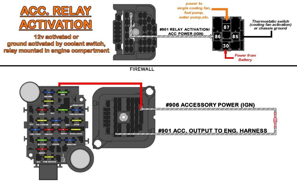
22 RELAYS & SWITCHES All ACCESSORY wires found in this harness can support up to 15 amps. Components requiring more amperage will need to be connected to a relay. An ACCESSORY wire can be used as a 12-volt activation source or 12-volt source for ground activation in these circumstances. Take a look at Painless part # s & to fill your relay needs at A 12 volt activated relay is constantly grounded. As the name implies, the relay sends power from the output side of the relay to the component being powered when 12 volts is applied. The 12-volt source can be wired directly to the relay or interrupted by a switch, as shown in the 12 VOLT SOURCE ACTIVATION drawing. Wiring directly to the relay, as indicated by the dashed line, would be used in the case of wiring a water pump relay or any other high amperage component you would want to run continuously while the key is in the on position. In these cases, make certain the 12- volt wire you are using is an Ignition Switched 12-volt wire and not a battery constant hot. The 12-volt activation wire can also be wired to a switch to offer the user OFF/ON capabilities. In these situations, a constant battery power source would be used. This would allow a component to be turned OFF or ON without the key in the ON position. However, unless a lighted switch is being used, a ground activated relay may work better to avoid running power through the switch. 13


23 A ground activated relay is just the opposite of the 12-volt activated relay; 12 volts (battery constant or switched) is supplied uninterrupted and the ground wire is switched. The Horn Relay pre-wired in the Painless harness is a Ground Activated Relay. Another example of this method is a thermostat operated fan relay. In this case, however, a thermostatic switch would replace the switch in the drawing above (see below). IN THE EVENT THAT A TOGGLE/ROCKER SWITCH IS BEING USED WITHOUT A RELAY, MAKE SURE THE AMPERAGE OF THE COMPONENT YOU ARE POWERING DOES NOT EXCEED THE CAPABILITIES OF THE SWITCH OR SWITCH FAILURE WILL OCCUR. IF YOU NEED A RELAY KIT PAINLESS OFFERS PART # S 30128, 30128, &
.")
24 This kit is supplied with a diode suppressed, weatherproof relay. This diode prevents the back-feeding of residual coil energy and voltage spikes when the coil is deactivated. Across the coil of the relay is a diode in reverse bias. When the power is applied to the coil, the 87 circuit closes (as seen in the diagram above). When the relay is deactivated, and 87 is open again, the residual energy in the coil is sent through the diode, the depletion region expands (see below), and the excess energy is dissipated. 15

25 OLD FACTORY HARNESS REMOVAL During the removal of the old, factory harness, avoid making any unnecessary cuts to any wires. The entire harness should be able to come out of the vehicle without any cutting at all unless someone has modified connections. Labeling the factory harness is highly suggested as it may be helpful to look back at the factory harness during the install of the new Painless harness. Plus, taking this step helps you identify anything that may not be included in the Painless harness and will need to be re-used. Individual wires and connectors can easily be labeled using masking tape. Take photos or make a drawing of any connections that have multiple connectors, like at the wiper motor, wiper switch, radio, etc. to help with reconnecting the new harness. In order to make the removal and installation of your new harness easier, it is necessary to remove the front grille, front side marker lights, the gauge cluster bezel, the gauge cluster, dash pad, glove box, driver side door sill plate, and driver side kick panel. Dome Lights: When disconnecting the dome light connection, there is no need to remove the wiring going behind the headliner, just simply unplug the inline connector that leads to the dome light. Cab Lights: Those trucks equipped with roofmounted marker lights, there is a black wire running to your headlight switch. The position of this wire is identified in the diagram to the right. This wire must be removed from the connector, so that the black wire stays in the truck when the rest of the interior harness is removed. This wire will later be re-connected to the headlight switch of the new Painless harness. Trucks with factory air conditioning, power locks/windows, and/or cruise control: These factory accessory harnesses DO NOT need to be removed during the removal process. They are their own separate harnesses. The power supplies for these separate harnesses simply need to be disconnected. Windows, locks, and cruise control are plugged into the front of the factory fuse block. The factory A/C harness receives power from an in-line connection at the A/C switch. Accessories wired to the firewall mounted junction block in the engine bay will need to stay put as well, only the chassis harness feed will be removed from the junction block. Trucks with a factory manual transmission: Two wires, light green and either dark green or dark blue, for the reverse switch run from the transmission into the interior of the truck through a hole in the firewall and plugs into the truck s chassis harness near the steering column. Leave this factory extension harness in place as the Painless comes set up for a factory automatic transmission with the reverse switch on the steering column. The factory extension harness will simply plug into the Painless harness reverse switch connector just as the factory harness did. 16

26 Fuel Sending Unit: At the fuel tank(s), if you do NOT have an in-tank fuel pump and you had a working fuel gauge before disassembly, you can cut the factory sending unit wire to avoid having to drop the tank or remove the bed in order to disconnect, and later, re-connect the fuel sending unit. Cut this wire far enough away from the grommet/frame to allow workroom for wire strippers and crimpers. Single pin, weatherproof connectors have been provided to make a trouble-free inline connection to this factory wire when installation takes place. Those with an in-tank fuel pump(s) there is already a factory two wire weatherproof connector you will just disconnect. Trucks with factory equipped Electronic Fuel Injection (TBI), electronic spark control, and/or computer controlled carburetors: This Painless harness does not contain any of the necessary wiring for these functions, nor will you find any instruction or tech help on how to incorporate the factory engine wiring into the new Painless harness. Painless does offer a separate TBI fuel injection harness, as well as other popular LS and Vortec EFI harnesses. We do not offer any solutions for computer controlled carburetors. 17
27 PRE-INSTALLATION GUIDELINES Before moving your new harness into your vehicle, it is a good exercise to lay the entire harness out and look over the individual sections that make up the harness. This allows you to get familiar with where specific wires are located and to move and regroup any wires necessary. All wires of this harness have ample length to account for the numerous different truck models and options the harness can fit. They are clearly marked to help ease the process of routing. This allows you to route your wires cleanly, and in the case of open-ended wires, terminate at the length you find fits your build best. The WIRE INDEX on page 143 helps to quickly identify each wire in each section. During this familiarization process is the perfect time to custom tailor your new Painless Harness to your particular vehicle. Use the following instructions to help get your harness ready for installation. DO NOT SKIP THESE PRE-INSTALLATION STEPS. Read through this entire manual before any wires are removed from the harness FUSE BLOCK / INTERIOR HARNESS Locate the Dome Light Section, these wires are open-ended. If you are not running an audio amplifier, and do not plan on ever connecting one, the BLUE #998 wire can be removed from the harness. The other end of this wire can be found in the Radio Section Locate the Seat Belt Relay connector on the top of the fuse block. Plug your factory seat belt relay into this. If you do not have a factory relay or factory seat belts with a switch, this connector and the wires going to it can be removed. YELLOW: 18 gauge wire, printed #990 SEAT BELT IND. LIGHT POWER, this wire goes to the Instrument Panel and sends a signal the seat belt light when the belt is not engaged. This is just a lay-in wire and can be removed if not used. BLACK/WHITE: 18 gauge wire, printed #980 SIGNAL FROM SEAT BELT, this wire goes to the Dome Light Section and connects to the seat belt. This is just a lay-in wire and can be removed if not used. BLACK: 18 gauge wire, not printed, this wire provides a ground to the seat belt relay. The BLACK #969 goes into a ground splice that will require cutting to be removed. PINK/BLACK: 18 gauge wire, printed #35 IGN POWER, this wire is a fused, switched ignition power source from the GAUGES fuse. This wire can be used to power another accessory if a seat belt relay is not being used. Locate the three wires that make up the Dimmer Switch. These wires are 14 gauge and colored LIGHT GREEN, TAN, and YELLOW. If you have a later model GM steering column with the dimmer switch on the bottom of the column, re-route the Dimmer Switch and group these wires with the Wiper Switch 18
28 Locate the Turn Signal Section, these eight wires will have terminals but no connector pre-installed. Two different connectors have been provided with this Painless kit to accommodate early and later model GM columns. Refer to the diagram on page 124 of this manual and install the appropriate connector your column requires at this time. If you are NOT running a Turbo 400 or a 700r4 automatic transmission, you can remove the ORANGE #911 throttle switch wire from the harness. It can be found with a PINK/BLACK #957 wire near the Brake Switch, Turn Signal Switch, and Ignition Switch wires. The PINK/BLACK #957 wire can remain as it is a fused, switched ignition power source from the CHOKE fuse and can power an additional accessory. Locate the Wiper Switch wires, these wires will have terminals but no connector preinstalled. These terminals fit switches. If you have a system, these terminals will need to be removed and factory terminals and the provided connectors, or your re-used factory connector, will need to be installed on the Painless harness. Switch pinout and photos of the connectors provided can be found on page 109, in the Wiper Switch portion of this manual. Also, those with a switch, your factory panel light socket will need to be reused, information on that can be found on page 109, in the Wiper Switch portion of this manual. On wiper switches, due to these connectors no longer being produced, the factory connector will need to be re-used. Refer to the removal process and install the re-used wiper switch connector onto the Painless harness according to the information in the Wiper Switch portion of this manual on page switches, a connector had been provided for your wiper switch in the bag kit. Pinout of this connector can be found on page 112, in the Wiper Switch portion of this manual. Locate the Instrument Panel Section, these wires will be terminated but no connector pre-installed. A connector has been provided with this kit, however it has not been installed due to the numerous different clusters that came in these trucks. Refer to the diagrams starting on page 129; then, find the cluster/pinout that matches your factory cluster and install the connector at this time. If aftermarket gauges are being used, now would be a good time to remove the wires not needed for your install or to re-route the instrument panel wires if your aftermarket gauges require a gauge control module to be wired. If you are running mechanical gauges, or if you are using an aftermarket gauge cluster or individual gauges that require their own 2 or 3-wire sensors, you can remove the sending unit wires running from the Engine Section to the Instrument Panel Section. 19
29 Locate the Fuel Tank Switch wires, these five wires are open-ended. Factory terminals have been provided to allow the factory connector to be re-used. Refer to the diagrams starting on page 104 and install your factory connector onto the Painless harness. Insulated terminals from the parts kit can also be used if you do not have a factory connector. These terminals will be installed on the harness during the installation process on page 104. Later style switches will need to re-use the factory ground wire, as shown on page 104. If you do NOT have dual fuel tanks, GREEN #999 and LT.GREEN #997 can be removed from the interior harness and the Tail Section harness. Before removal of these wires, if you plan on running an electric fuel pump to a carburetor, make sure to read the instruction on page 76 as one of these wires can be re-purposed. The PINK/BLACK #947 can be used to power another accessory or a lowpressure electric fuel pump. The PINK #939 and the TAN/WHITE #939 MUST remain and MUST be connected together as the TAN/WHITE #939 delivers the fuel sender signal from the tank, and the PINK #939 wire carries this signal to the instrument panel. ACCESSORY SECTION: GRAY/WHITE #906: This wire provides a fused switched ignition power source from the 15 amp CHOKE fuse. Re-route the GRAY/WHITE #906 in the harness to wherever the accessory is located. GRAY/WHITE #901: This wire goes from the Accessory Section on the inside of the truck, through the bulkhead and out into the Engine compartment and grouped with the Headlight Section. Connect the #906 to the #901 to provide power to an accessory in the engine compartment, not exceeding 15 amps. In most cases this is to provide power to the activation (86) of a cooling fan relay. This is further explained beginning on page 97. TAN #903: This wire provides a fused battery power source to the cigarette lighter/power port, nothing needs to be done at this time. ORANGE/BLACK #913: This wire provides a fused battery power source for power door locks. If you still have your factory lock harness in your truck, the factory harness can plug into the fuse block as shown on page 12. For a cleaner install of a factory set up, or for those wiring aftermarket door locks, nothing needs to be done at this time. PINK #912: This wire provides a fused switched ignition power source for power windows. If you still have your factory window harness in your truck, the factory harness can plug into the fuse block as shown on page 12. For a cleaner install of a factory set up, or for those wiring aftermarket power windows, nothing needs to be done at this time. 20

 pins comes directly from the ignition switch.")

30 ENGINE BULKHEAD Highlighted in the photo to the right, you will see that there are two pins with a terminal pre-installed. Both of these pins will have power when the ignition key is in the ON / RUN position. This will make wiring up most underhood accessories requiring a switched power source easier than having to source power from the inside of the vehicle. The ignition switched power source on these (2) pins comes directly from the ignition switch. These pins are both UNFUSED and must have an inline fuse (not supplied), no larger than 10 amps, installed before being routed to a component needing power. If you need to power a component needing more than 10 amps, a relay will need to be installed. See relay wiring and activation on pages for detailed schematics. If you do connect one or both of these pins to a relay, be sure they are connected to the 12v activation 86 terminal on the relay. Looking at the mating bulkhead connector on the engine harness, as seen to the right, you will notice the wires for the ignition switched pins are not populated. This is to prevent un-fused wires running out into the engine compartment. There is no harm in leaving these ports open if you do not require any additional switched power sources. In order to utilize these switched power sources, you must add wires to the engine harness bulkhead. Terminals have been provided in the parts kit for these connections (see page 22). These terminals will accept gauge wire, using a ¼ strip length, and are easiest to install with a non-insulated terminal crimp tool, shown on page 4, and demonstrated below. If any wires were added to the bulkhead connector, group each wire with the section of Engine Harness nearest to where the fuse will be installed. For instance, if you are mounting an inline fuse on the driver side inner fender to power an accessory, the wire leading to it will route with the Front Light Section. 21
, and relay activation.")

31 BULKHEAD PINOUT The engine harness is broken down into 4 major groups of wires leaving the bulkhead connector: Front Light Section: contains wiring for the brake warning switch, headlights, high beams, marker lights, park/turn signals, horn(s), and relay activation. Wiper Section: contains wiring for the wiper motor and washer pump Engine Group: contains 4 sub-groups of wiring o Alternator contains wires need for the charging system o Engine Section contains wiring for oil pressure, temp sensor, electric choke o MIDI contains a single wire for the MIDI fuse. o Starter Solenoid contains a single wire from the NSS to the starter solenoid. Tail Section: contains the fuel level signal and dual tank signal wires as well as the marker, turn/brake, tail, reverse, and license plate lights. Look over the pin out to see if there are any wires you will not be using. Things like electric choke, gauge wires (if you are using mechanical gauges or aftermarket gauges requiring their own sensor wires), and the tachometer wire are all things some people may not be using. These unused wires can be capped, using insulated butt connectors and stowed away neatly. However, you may choose to remove these unused wires in order to clean up the install and to keep unnecessary wires from being taped or wrapped up in the harness. Read through this entire manual before any wires are removed. Some wires can be repurposed and used for other things. UNDER NO CIRCUMSTANCES SHOULD YOU REMOVE ANY OTHER WIRES. Removal of these wires is simple and will require the use of a pair of pliers and/or a flat head screwdriver. Squeeze the smaller side of the terminal in towards the center of the terminal. This will allow the terminal to be pulled free of the bulkhead Be careful not to damage any of the surrounding terminals & wires. 22

32 If you have an externally regulated alternator, and the regulator is mounted on the driver side core support, re-routing of the Alternator Section and additional wiring (not included) will need to be added to the Lighting Section of the engine harness. See the Start/Charge Section beginning on page 57 for details on these wires before routing any of the Light Section. For trucks with a single fuel tank, locate the PINK #939 in the Tail Section. This wire will need to be routed with the Engine Section as the fuel sender connection will route down the passenger side frame to the fuel tank. Dual tank trucks can leave this wire in the Tail Section. If you are using a one wire alternator, the WHITE #914 and RED #995 wire can be removed since your alternator will not require these wires. If you have a vehicle, you will need to change out the WIPER/WASHER strip on the bulkhead. A separate bulkhead strip, with different wire colors and connectors pre-installed, can be found in the kit. Simply pry the end of the engine bulkhead off the main connector and install the other piece to accommodate your earlier wiper system vehicles do nothing with this extra bulkhead piece, your correct wiper motor wires are already installed on the bulkhead. Although, the factory washer pump connector from trucks will need to be re-used. These washer pumps are mounted to the wiper motor; see page 32 for the correct pinout. For trucks with a reservoir mounted washer pump group the two washer pump wires with the Head Light Section so the washer pump wires can be routed to their location along with other wires that need to attach to the inner fender. Painless does not recommend removing any power wires from the fuse block as they can possibly be used to power other things. When bundling wires into groups, use cable ties, split loom, or tape. The exposed wires in the engine compartment and wires running to the rear of the vehicle are best protected by wire loom or covering. Painless offers the Power Braid Kit part #70920 and the Classic Braid #70970 to fill this need. These kits include everything you need to properly protect your new chassis harness. 23


33 FUSE BLOCK MOUNTING The Painless fuse block and bulkhead will fit the factory firewall opening left behind by the factory bulkhead. Locate the two 3 coarse threaded machine screws from the parts kit. These screws are used to mount the fuse block to the firewall utilizing the factory mounting holes. Install the fuse block onto the firewall by inserting the screws through the fuse block mounting holes in the upper right and lower left part of the fuse block. Using a 5 16 nut driver/socket or a flat blade screwdriver, tighten the screws to secure the fuse block. ENGINE BULKHEAD MOUNTING Find the tube of dielectric grease in the parts kit and apply a small amount of grease into each terminal of the Engine Bulkhead Connector. Push the engine bulkhead onto the firewall connector as far as you can, it will not go all the way on because of the bolt. Make sure the connector is on straight. The terminals of the bulkhead will easily bend Using a 3 8 socket, tighten the mounting thru bolt on the engine bulkhead to the firewall connector. DO NOT FORCE OR OVERTIGHTEN! 24
34 BEFORE ROUTING THE ENGINE HARNESS The routing of the Engine/ Headlight Harness, covered in the next section, follows much of the factory harness routing. It will be up to you, the installer, to position all wires away from sharp edges, hood hinges, moving parts and exhaust heat. Umbrella style clips for cable ties have been provided for you to attach the Painless harness to the inner fender and the core support in the same fashion the factory did. These cable tie clips fit into the ¼ holes left behind by the factory plastic retainer loops, or those you drill yourself. Remember, as the cable ties are installed and the harness is routed, wrap the tie around the harness and LOOSELY tie the harness to the mounting surface. Make sure you leave enough room to pull and push the harness as you make your connections. Only when all connections are made, will the cable ties be tightened. 25

35 HARNESS ROUTING Loosely route all of the wire groups to their designated connection points. NO CONNECTIONS OR CUTTING WILL TAKE PLACE AT THIS TIME. Harness routing is and should be a time-consuming task. Taking your time will enhance the appearance and quality of the installation. Please be patient and TAKE YOUR TIME. REMEMBER TO ROUTE THE HARNESS AWAY FROM SHARP EDGES, EXHAUST PIPES, HOOD, AND DOOR HINGES, ETC. WHILE ROUTING WIRES: If you are to go through an inner fender well, core support, or any other metal pass-through YOU MUST INSTALL A RUBBER GROMMET. HEADLIGHT SECTION Route the Head Light Section along the inner driver side fender to the core support. Secure the harness to the fender with the factory loom clips or use the umbrella clips and cable ties. Once at the core support, isolate the wires for the left-hand side headlight and turn signal and possibly the horn wire, depending on where the horns are located. If the GRAY/WHITE #901 is being used to power a component, take its connection point into consideration before routing wires to the passenger side. 26


36 Route the wires for the right side lights across the core support to the passenger side of the vehicle. The factory ran these wires two different ways: Earlier years, these wires were routed across the top of the core support under the radiator hold down. This routing of the Head Light Section makes good use of the cable tie clips. Install these clips and loosely tie the harness in place. Later years, these wires were routed through the bottom of the core support, then along the front of the core support behind the front bumper, then back through the core support once past the radiator on the passenger side. ENGINE & TAIL SECTIONS Route the Engine Section & Tail Section down away from the bulkhead, under the steering shaft, and mount to the firewall using the factory harness strap. If desired, the Engine Section can also route up from the bulkhead, above the brake booster and across the firewall in the factory plastic channel that houses the washer nozzle hoses. At the strap, route the Engine Section up to the left of the brake booster and then across the firewall. These wires are easiest to route to their final location when their specific connections are made. Route the Tail Section down to the frame and back towards the rear. Be sure to avoid routing wires around any transmission shift linkage. 27

37 If you have dual fuel tanks, the #939, #997, & #999 wires will need to be routed across the frame to the passenger side on the cross brace just behind the driver side door and not routed to the rear of the vehicle. At the back of the vehicle, route the wires to the left and right connections as indicated by the print found on the wires. The #929 and #956 will route to the driver side lights and will require installer supplied splices to run across to the passenger side lights. This will be explained in more detail later on pages 79. Route the Engine Harness wires to the center of the firewall in the engine compartment. The factory routed these wires down away from the bulkhead, under the steering shaft, and then up to the left of the brake booster and then across the firewall. These wires are easiest to route to their final location when their specific connections are made. INTERIOR HARNESS Route the wires intended for dash mounted components/switches towards their connection points on the dash at this time. When routed correctly, the gauge cluster branch of wires should be at the upper, left-hand side of the dash opening, and the A/C - Heater, Radio, and Accessory Sections at the upper, right-hand corner of the opening. Secure the harness across the top of the underside of the dash using the factory harness straps. Wires found in the Accessory Section are easiest to route to their final location when their specific connections are made. The Head Light Switch, and Wiper Switch, will be routed when those components are connected. The steering column connections that come out of the side of the fuse block will follow the factory routing across the firewall, re-using the factory hold down clamp. These connections will hang loosely at the steering column at this time. Once all the wires are routed and running to the general location of their components, you can begin making connections. We prefer to start with the Head Light Section and work from the front of the vehicle to the back. 28
38 ENGINE HARNESS CONNECTIONS WIPER MOTOR SECTION Two different wiper motors were used during the production of these trucks. To accommodate this change, and to provide you with the necessary parts, an additional bulkhead piece has been provided. If you have a vehicle, you will need to change out the WIPER/WASHER strip on the bulkhead. A separate bulkhead strip, with different wire colors and connectors pre-installed can be found in the kit. Simply pry the end of the engine bulkhead off the main connector and install the other piece to accommodate your earlier wiper system. Those with motors (seen on the next page) will not need this other bulkhead piece; the one pre-installed in the bulkhead has the correct connectors and wire colors for your pump. WIPER MOTOR ( ) The following wires, except for the YELLOW wires leading to the wiper motor and the washer pump, provide grounds to the wiper motor and washer pump from the switch. These wires have connectors pre-installed. Due to their short length they are unable to be printed on; their functions are: YELLOW: 16 gauge wire, not printed, this wire provides power to the washer pump. This wire will only have power, from the 15 amp WIPERS fuse, when the ignition switch is in the ON/RUN position. BLUE: 16 gauge wire, not printed, this wire provides a ground activation source to the washer pump from the wiper switch. BLACK: 16 gauge wire, not printed, this wire provides a ground activation source to the wiper motor for LOW speed. YELLOW: 16 gauge wire, not printed, this wire provides power to the wiper motor. This wire will only have power, from the 15 amp WIPERS fuse, when the ignition switch is in the ON/RUN position. LIGHT BLUE: 16 gauge wire, not printed, this wire provides a ground activation source to the wiper motor for HIGH speed. Connect the wiper motor connector to the wiper motor. The connector is keyed to the terminals so it can only go on one way. Connect the washer pump connector to the pump. The connector is keyed to the terminals so it can only go on one way. 29


39 The following wires, except for the WHITE wire to the wiper motor and WHITE #981 to the washer pump, provide ground to the wiper motor and washer pump from the switch. These wires have connectors pre-installed. Due to their short length they are unable to be printed, their functions are: Connector 1: Park Switch BLACK/BLUE: 18 gauge wire, not printed, this is a signal to the park switch. GRAY/WHITE: 18 gauge wire, not printed, is a low speed-park switch signal Connector 2: Wiper Speed PURPLE: 18 gauge wire, not printed, this is a signal to the high-speed tab on the wiper motor. WHITE: 18 gauge wire, not, this wire supplies switched ignition power to the wiper motor from the 15 amp WIPER fuse on the fuse block. GRAY/WHITE: 18 gauge wire, not printed, is a low-speed signal Plug the two wiper motor connectors onto the wiper motor. 30

![WHITE: 18 gauge wire, printed [WIPER PUMP] #905 WASHER POWER (IGN), this wire supplies switched ignition power to the washer pump from the wiper motor.](/docs-images/92/109533477/images/40-1.jpg "These wires can be seen in the Wiper Schematic below. On 1977 1984 models with a wiper motor mounted washer pump, like the one seen on the previous page, you will need to reuse the original connector.")

40 WASHER PUMP The washer pump receives a ground signal from the wiper switch to activate the pump. Once activated, it pumps washer fluid from the reservoir to the washer nozzles. PINK: 18 gauge wire, printed [WIPER PUMP] #983 WASHER ACTIVATION, this wire provides the washer pump with a ground source from the wiper switch when the switch is in the WASH position. WHITE: 18 gauge wire, printed [WIPER PUMP] #905 WASHER POWER (IGN), this wire supplies switched ignition power to the washer pump from the wiper motor. These wires can be seen in the Wiper Schematic below. On models with a wiper motor mounted washer pump, like the one seen on the previous page, you will need to reuse the original connector. To remove the terminal, the connector s terminal lock will need to be pried up. The locking tang of the factory terminal will need to be depressed to remove the terminal. This locking tang will be on the opposite side of the connector terminal lock. Cut the wires to length and install the provided terminals using rollover crimpers. Install the newly terminated wires into their proper location on the factory connector as indicated below. Then, plug it into the washer pump. Pin A= White Pin B= Pink 31


41 On models, the washer pump was located on the back side of the fender mounted washer reservoir. Removal of the reservoir will be necessary to access the pump. A factory style connector and terminals have been provided. Route the PINK #983 and WHITE #905 to the pump and cut to length. Strip ¼ insulation and crimp on the new terminals. Install the wires into the connector as shown in the photo. 32


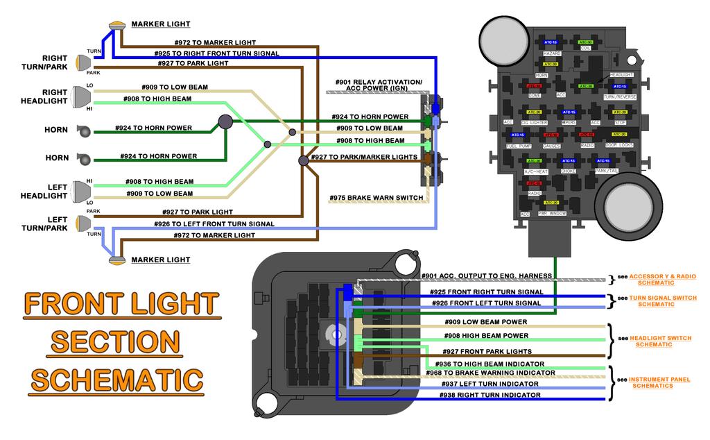
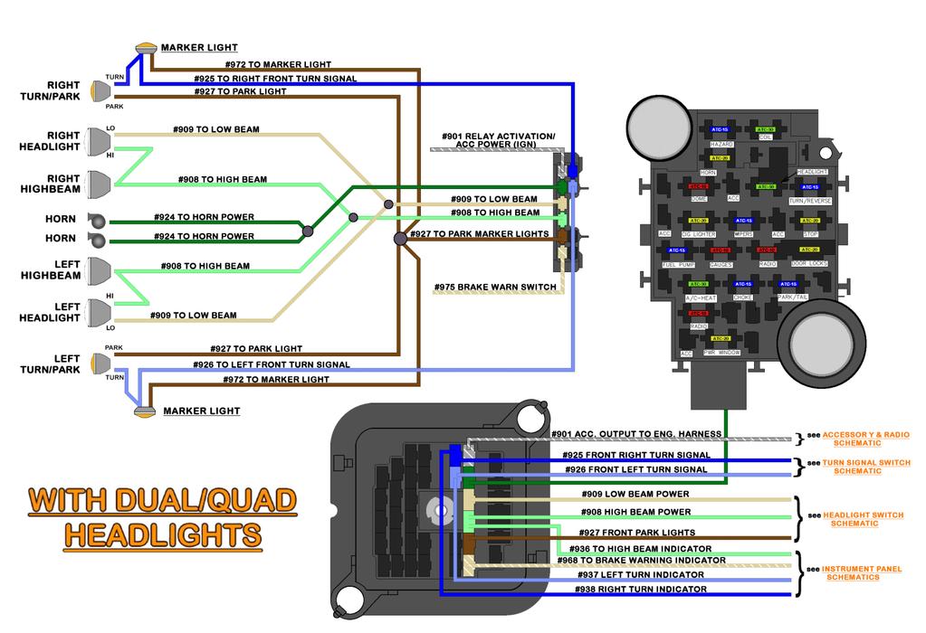
42 FRONT LIGHTING SECTION The Head Light Section of this Painless Harness includes all power wires needed to properly hook up both driver and passenger side headlights, front turn signal lights, and park/marker lights. There is also a power wire from the fuse block mounted horn relay to power the horns. All wires in the Head Light Section can be seen in the Front-Lighting Schematics on page Two separate small front ground harnesses are provided to provide ground solutions to the driver side and passenger side lights. If halogen bulbs are being used, a separate headlight relay kit MUST be used. Due to the higher amperage demands of halogen lights, these lights will often cause the circuit breaker in the headlight switch to fail. A headlight relay harness provides battery power through the relays directly to the headlight bulbs. The headlight switch will activate the relays, thus drawing less than 1 amp of current. This is beneficial for both the longevity of the headlight switch and the brightness of headlight bulbs themselves. Painless offers part #30814 for dual/quad headlights and #30815 for single headlight vehicles. 33

43 LIGHT CONFIGURATIONS Four different factory front ends can be bolted to the front of the Square Body truck. The wires required for connecting the Head Light Section will be dependent on what front end you are using, more specifically, how many headlights you have. Painless offers light socket kits to help wiring these different front ends and to keep installs from reusing old factory sockets: Socket Kit # Single Round Headlights Socket Kit # Dual Headlights Socket Kit #30351-Single Square Headlights Socket Kit # Suburban/Jimmy These socket kits will include (2) front Turn Signal socket pigtails, (4) Marker Light pigtails for front and rear, (2) Brake/Tail Light socket pigtails, and (2) Reverse Light pigtails. Splices and heat shrink are also included to complete your connections. The rear sockets included in these kits will NOT fit step side trucks as those lights are hard-wired with molded connectors that must be reused. GROUNDS There are 2 separate four-wire ground harnesses in your kit. Each harness includes: A single 12 gauge main chassis ground wire, printed #969 TO CHASSIS GROUND, intended to connect to the factory grounding bolt on the core support Two 14 gauge wires, printed #969 HEADLIGHT GROUND and #969 HIGH BEAM GROUND. These wires will route with the other wires of the Painless ground harness to the headlight and separate high beam, if equipped. A single 18 gauge wire, printed #969 TURN SIGNAL GROUND, will provide a ground source to the front turn signal. Modification to each harness may be necessary depending on your headlight configuration. If you have dual high beam headlights, no modification will be required. 34

44 If you have a single headlight on each side of the truck, the high beam ground wire from the front light harness can be removed. This wire can also have a ring terminal installed and connected to chassis ground, or just rolled up and stowed in the harness. Using the provided tape or cable ties, lay the wires of one of the ground harness into the wiring for the driver side lights. Also, use the tape or cable ties to group the headlight, turn signal, and marker light wires together at this time; thus, further incorporating the ground harness with the Painless harness. 35

45 LEFT / DRIVER SIDE HEADLIGHT Your first connection in the Head Light Section will be the Left/Driver Side Headlight. Three wires make up the connection to the Left Headlight, they are: LIGHT GREEN: 14 gauge wire, printed [HEADLIGHT SECTION] #908 TO HIGH BEAM, this wire provides power to the high beam filament of the headlamp. This wire comes from the dimmer switch and has power when the dimmer switch is in the high beam position and the headlight switch is in the headlight ON position. TAN: 14 gauge wire, printed [HEADLIGHT SECTION] #909 TO LOW BEAM, this wire provides power to the low beam filament of the headlamp. This wire runs from the dimmer switch and has power when the dimmer switch is in the low beam position and the headlight switch is in the headlight ON position. BLACK: 14 gauge wire, printed #969 HEADLIGHT GROUND. This wire is part of the separate ground harness and provides a ground to the headlight. If your vehicle is equipped with dual/quad headlights, meaning the vehicle has a high/low beam light and also a separate high beam light on each side, double up the cutoff piece of the LIGHT GREEN #908 wire to power the separate high beam. A separate #969 HIGH BEAM GROUND wire is provided. The illustration on page 45 demonstrates this. Connectors, shown on the next page, have been provided in the parts kit to allow proper connection to standard H4, 2 or 3-prong headlights. Route the 3 wires for left/driver side headlamp connection to the back of the headlamp. Cut all 3 wires to length and strip a ¼ of insulation from them. Locate the headlight terminals from the bag containing the headlight connectors. These terminals look like other terminals supplied in the parts kit. You will be using the larger, wider terminals as shown in the photo. Also, a few of these headlight terminals will have longer crimp straps or deeper wells than the others. These terminals are for those with dual headlights that need to double up two LIGHT GREEN #908 wires into one terminal. Install terminals onto each wire, making sure to double the high beam wire if you have a separate high beam (quad-headlight). Use the connector photo on the next page for proper wire pinout. The connector is shown from the wire insertion side. Please notice that 1987 models have a different pinout than a standard H4 bulb that was used in all previous years. 36


46 After pinout is complete, dab a little dielectric grease on the terminal end of the connector before plugging it onto the headlamp. It will help protect against corrosion and make the headlamp easier to unplug next time it needs servicing. Plug the connector onto the prongs of the headlamp. Make sure the connector is inserted straight onto the prongs as these prongs will easily bend making a proper connection difficult. Those with separate high beams will use the same 3 cavity connector as the high/low beam headlight even though the high beam only has 2 prongs. You will only use the side cavities labeled #969 and #908 seen above. LEFT PARK / SIDE MARKER LIGHT The driver side, fender mounted marker light is the next connection. The park light feature is activated by a power source coming from the headlight switch. This light illuminates any time the headlight switch is in the PARK or ON position. The turn signal feature is provided by a power source coming from the turn signal switch. 37

47 The left side marker requires two wires to work properly. These wires are: BROWN: 18 gauge wire, printed [HEADLIGHT SECTION] #927 TO MARKER LIGHT, this is a power wire for the park or marker light function. This #927 is tied to the other #927 wires in the Front-Lighting Section. This wire has power anytime the headlight switch is in the Park/Tail Lights ON or Headlights ON position. LT. BLUE: 16 gauge wire, [HEADLIGHT SECTION] #926 TO LEFT FRONT TURN SIGNAL, this wire is the power for the turn signal function. This wire comes from the turn signal switch and has interrupted switched power from the turn flasher anytime the left turn signal is activated. It also receives interrupted battery power from the hazard flasher anytime the hazard switch is in the ON position. Your factory socket or a pigtail from a Painless socket kit will be needed. These sockets use a wedge base #194 bulb, not included. Splices and heat shrink from the parts kit will also be needed. Looking at the back of the marker lamp housing, you will see that it has a keyed opening to correspond with the tabs on the socket (as seen in the photo). Temporarily install the socket into the marker light assembly. Removal of the lens may be necessary. Route the BROWN #927 wire to one wire on the socket, it doesn t matter which one, and cut the #927 to length. Route the LT. BLUE #926 wire to the other wire of the socket and cut the #926 to length, save the cut off piece of #926. Using splices and heat shrink from the parts kit, connect the #926 and #927 wires to the lamp socket. Double up with the cut off piece of #926 with the #926 wire going to the socket. This allows connection to the front turn/park light as shown in the diagram below. On these side marker lights you will notice that there are no means for a direct ground to be applied to the light. This is because the path to ground will travel from this park/side marker socket to the front turn signal socket, through either one of the wires, and ground through the front turn/park light. The front turn/park signal socket is a higher wattage bulb. So, when the ground passes through that bulb it will not cause the front lamp to illuminate since it has a greater power requirement than the side park/maker light. 38


48 LEFT TURN/PARK LIGHT The Left Turn/Park Light of the Painless harness consists of 3 wires. These wires are: BROWN: 18 gauge wires, printed [HEADLIGHT SECTION] #927 TO PARK LIGHT, this wire provides power to the park lights. This wire splices to a single BROWN wire leading to the headlight switch. This wire has power anytime the headlight switch is in the Park/Tail Lights ON position. LT. BLUE: 16 gauge wire, printed [HEADLIGHT SECTION] #926 TO LEFT FRONT TURN SIGNAL, this wire is the turn signal power. This wire has interrupted switched power from the turn signal flasher any time the left turn signal is activated and the ignition is in the ON position. It also receives interrupted battery power from the hazard flasher any time the hazard switch is in the ON position. BLACK: 18 gauge wire, printed #969 TURN SIGNAL GROUND, this wire provides a ground source for the turn/park lamp. It is located in the separate, front ground harness. See Front-Lighting Ground Schematic on page 46. Your factory socket or a pigtail from a Painless socket kit will be needed. These sockets use a #1157A bulb, not included. Splices and heat shrink from the parts kit will also be needed. Route the wires needed for installation to the turn signal. Cut the 3 wires to length and strip ¼ of insulation from all wires. For those with turn signals mounted in the grille, it will be necessary for the grille to be removed in order to access the back of the turn signal lens. 39


49 DRIVER SIDE GROUND Now that all driver side light connections have been made, the ground can now be connected. Using a ring terminal from the parts kit, connect the 12 gauge wire, printed #969 TO CHASSIS GROUND, to a clean, bare metal spot on the core support. The factory grounding point above the headlight is ideal. BRAKE PRESSURE WARNING SWITCH The brake pressure warning switch is located on the brake proportioning valve. The proportioning valve is located toward the front of the vehicle, near the radiator. This switch requires a single wire, it is: TAN/WHITE: 18 gauge wire, printed [HEADLIGHT SECTION] #975 BRAKE WARN SWITCH, this wire will provide a ground signal through the bulkhead to the brake indicator light on the instrument panel when there is an issue with your brakes. A connector and terminal have been provided to make this connection. You may also cut the factory molded connector from your factory harness and create your connection using a splice and heat shrink sourced from the parts kit. Route the #976 wire to the brake warning switch, cut to length, strip ¼ of insulation from the wire, and connect in your preferred manner. FAN RELAY/ACCESSORY This Painless harness does not include any wiring specifically for a fan relay. There is a GRAY/WHITE #901 wire in the Headlight Section that can be used for a 12v activation. This wire can be used for the activation of the relay coil only and MUST NOT be used to directly power a cooling fan. This wire can also be used to power a component needing a switched ignition power source. This wire is: GRAY/WHITE: 16 gauge wire, printed [HEADLIGHT SECTION] #901 RELAY ACTIVATION/ ACC POWER (IGN), when connected to GRAY/WHITE #906, this wire provides a fused switched ignition power source from the 15 amp CHOKE fuse. Refer to the relay diagram to use this wire to power the activation side of a relay coil. If you are using this wire to power another aftermarket accessory, consult the manufacturer s instructions and verify the component, and any other components in this harness on the CHOKE circuit, do not draw more than 15 amps combined. 40
50 41

![These wires are: (2) GREEN: 14 gauge wires, printed [HEADLIGHT SECTION] #924 TO HORN POWER, these are power wires that come from the fuse block mounted horn relay.](/docs-images/92/109533477/images/51-2.jpg "These are ground activated by the horn button on the steering column and only have power when the horn button is pressed.")
51 HORN(S) The Head Light Section has two wires dedicated for connections to the horns, usually mounted on the front of the core support, on either side of the radiator. Most horns ground through their mounting and only require a power connection. These wires are: (2) GREEN: 14 gauge wires, printed [HEADLIGHT SECTION] #924 TO HORN POWER, these are power wires that come from the fuse block mounted horn relay. These are ground activated by the horn button on the steering column and only have power when the horn button is pressed. Grommets have been provided for those who are passing the wire harness across the top of the core support. These grommets will fit the holes on either side of the radiator that the factory horn wires passed through. Please be aware that there are other grommets provided with this harness that are for interior connections, DO NOT use the wrong grommets. Route the #924 wires to each horn; install the provided grommets if needed. Cut the wires to length and strip ¼ of insulation. Connectors and terminals have been provided to connect to the horns. 42
52 RIGHT TURN / PARK LIGHT & HEADLIGHT The connections on the right/passenger side of the vehicle all connect in the same manner as those on the left/driver side. The only difference you will find is the turn signal wire for the right turn signal is a different color than the one used for the left turn signal. The right turn signal will be: BLUE: 16 gauge wire, printed [HEADLIGHT SECTION] #925 TO RIGHT FRONT TURN SIGNAL, this wire is the turn signal power, and goes to the turn signal switch. This wire has interrupted switched power from the turn signal flasher any time the right turn signal is activated and the ignition is in the ON position. It also receives interrupted battery power from the hazard flasher any time the hazard switch is in the ON position. NOTES 43
53 44
54 45
55 46
56 47


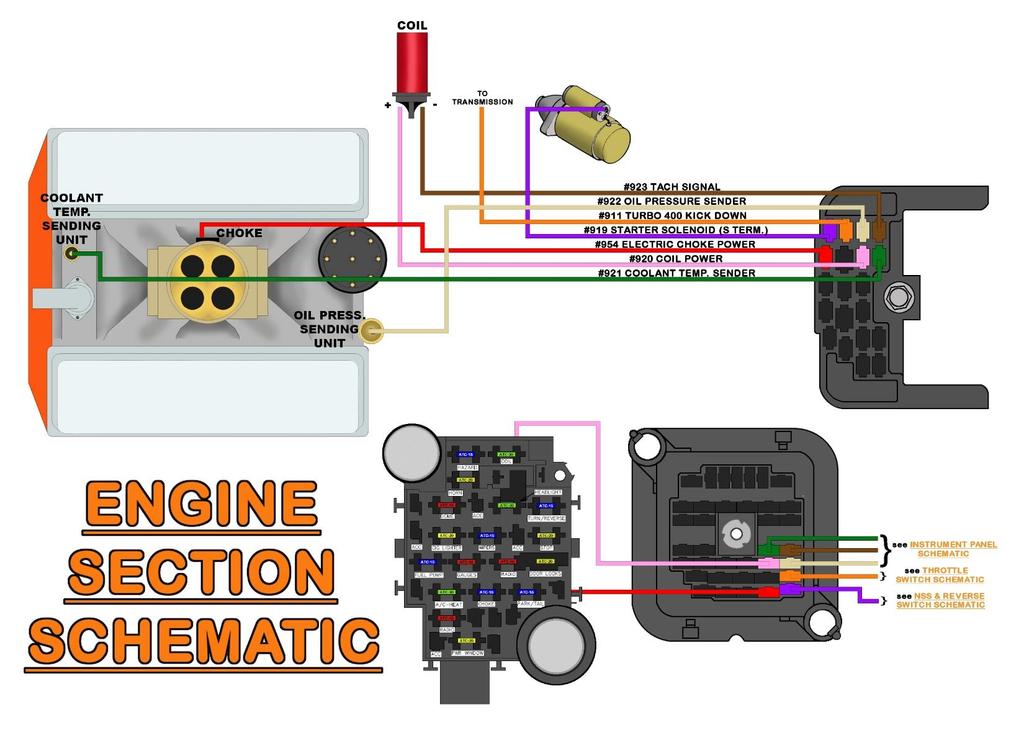
57 ENGINE SECTION CONNECTIONS The Engine Section consists of seven wires. They connect to the oil pressure and coolant temperature sending units for gauges or lights, the coil or ignition system, tachometer, starter solenoid, 700R4 or Turbo 400 kick down, and an electric choke on a carburetor. *Note the #919 PURPLE wire, though grouped with the Engine Section, will be covered in the Start/Charge Section beginning on page 57. COOLANT TEMP SENSOR GREEN: 18 gauge wire, printed [ENGINE SECTION] #921 COOLANT TEMP. SENDER, this wire sends a ground signal to the engine coolant temp gauge. If you are using an aftermarket mechanical gauge, this wire is not needed. See the Engine Section Schematic on page 47. The coolant temp sending unit/switch can be mounted in the intake manifold or in the side of either cylinder head. These will have a peg, tab, or threaded post to connect to, as seen in the photos on this page. Terminals and a factory style connector have been supplied to allow connecting to a factory style sensor, rollover crimpers will be needed to properly install this terminal. Two-wire temperature sensors on fuel injected engines are for engine computer input, not for gauge signal. Also, if connecting to an engine in a vehicle that has electric cooling fans, make certain you know the difference between the coolant temp sensor and the electric fan thermostatic switch; both of these sensors can look identical. 48


58 If you are installing a new temp sensor, or are unsure of the temp sensor currently mounted in your engine, make sure there is no sealant tape on the sensor threads. The tape can interfere with the ground source the sensor needs to read correctly. Anti- Seize can be used on the threads. Route this GREEN #921 wire to the coolant temp sensor, cut to length, crimp on the appropriate terminal for your connection, and connect. OIL PRESSURE SENSOR TAN: 18 gauge wire, printed [ENGINE SECTION] #922 OIL PRESSURE SENDER, this wire sends a ground signal to the oil pressure gauge. If you are using an aftermarket mechanical pressure gauge, this wire is not needed. See the Engine Section Schematic on page 47. The oil pressure sending unit will generally be located near the oil filter or on the back of the block behind the intake manifold. Route the TAN #922 wire to the oil pressure sending unit, crimp-on the appropriate terminal for your connection, and connect. 49

![ELECTRIC CHOKE RED: 16 gauge wire, printed [ENGINE SECTION ] #954 ELECTRIC CHOKE POWER, this wire provides a switched ignition power source to the choke from the 15 amp CHOKE fuse.](/docs-images/92/109533477/images/59-2.jpg "It has power when the ignition switch is in the ON/RUN position. See the Engine Section Schematic on page 47.")

59 If you have a 2-wire sensor on a newer, fuel injected, donor engine, it will not work for your pressure gauge. Two-wire sensors on fuel injected engines are for fuel pump control and are not designed for oil pressure gauge readings. These types of sensors are generally found on GM TBI and TPI engines. ELECTRIC CHOKE RED: 16 gauge wire, printed [ENGINE SECTION ] #954 ELECTRIC CHOKE POWER, this wire provides a switched ignition power source to the choke from the 15 amp CHOKE fuse. It has power when the ignition switch is in the ON/RUN position. See the Engine Section Schematic on page 47. When you turn your key to the ON/RUN position, the current this wire carries heats the bimetal spring attached to the shaft of the choke. This spring will unravel as it is heated causing the choke to slowly open. When the ignition is turned to the OFF position, power is no longer on this wire, causing the spring to begin to cool and contract, closing the choke. If you do not have an electric choke, you do not need this wire, and it can be capped off and stowed. Route the RED #954 wire to the + terminal of the electric choke. Install the supplied terminal and connector then connect. Ensure the choke is properly grounded (the ground wire is not supplied in the Painless harness) before continuing with the installation. 50
![TURBO 400 / 700R4 TRANSMISSION A single wire is provided for those running a Turbo 400 or 700r4 transmission. This wire is. ORANGE: 16 gauge wire, printed [TRANSMISSION] #911 TURBO 400 KICK DOWN.](/docs-images/92/109533477/images/60-0.jpg "This wire will provide a switched ignition power source from the throttle switch, (Turbo 400) or brake switch (700r4).")
60 TURBO 400 / 700R4 TRANSMISSION A single wire is provided for those running a Turbo 400 or 700r4 transmission. This wire is. ORANGE: 16 gauge wire, printed [TRANSMISSION] #911 TURBO 400 KICK DOWN. This wire will provide a switched ignition power source from the throttle switch, (Turbo 400) or brake switch (700r4). Please be aware, those with a 700r4 transmission will still need to use their factory transmission-vacuum switch harness, or Painless part #60109, as the single wire provided in the Painless harness is only part of the wiring needed. Turbo 400 The Turbo 400 transmission requires a 12v power source to downshift the transmission under wide open throttle. This is done through the use of a throttle switch. The throttle switch is either located on the accelerator pedal inside the vehicle or, if using an aftermarket switch, on the throttle linkage on top of the engine. If you have a factory, pedal mounted accelerator switch, route and connect the exterior ORANGE #911 wire to the transmission. There are 2 wires in the interior harness that supply power to and from the throttle switch. These wires are covered in more detail in the Throttle Switch Section on page 116. If you have an engine mounted throttle switch, you ll have to take a few extra steps. Route the exterior ORANGE #911 kick-down wire to the throttle switch, cut-to-length, and connect. Save the cut off portion. Attach the cut off portion ORANGE #911 to the output tab on throttle switch, then route to the transmission, and connect. Then, when the time comes to complete this circuit on the interior, splice together the PINK/BLACK #957 and the interior ORANGE #911 power wire. See the diagram on the next page. 51


61 700R4 These transmissions used a low vacuum switch, usually mounted on the firewall, and a brake switch to control power to the torque converter clutch solenoid in the transmission. Once power is interrupted, the converter will unlock if it has been engaged. Those with an aftermarket, non-lockup torque converter will need no electrical connections to the transmission. Route the #911 wire to the vacuum switch and cut to length. A terminal has been provided to fit the vacuum switch connector. If this Painless harness is being installed in a vehicle using one of our 700r4 lockup kits, part #60109, this #911 wire can connect to the PURPLE wire of that kit which normally runs inside to the brake switch. Reference the diagram on the next page. The other side of the vacuum switch should connect to Pin A of the 4-pin connector that goes to the transmission. 52
 you use.")
62 COIL / IGNITION SECTION A single wire, coming from the fuse block, supplies power to the coil/ignition system. The connection of this wire varies depending on what ignition system (factory or aftermarket) you use. The wire needed to supply a switched ignition power source is: PINK: 14 gauge wire, printed [ENGINE SECTION] #920 COIL POWER, this wire comes from the 30 amp COIL fuse. This wire has power anytime the ignition switch is in the ON and START positions. This wire provides the coil/ ignition system with switched power in 1 of 4 ways: If the Coil you are using is not internally resisted, a ballast resistor, along with the installer provided bypass wire shown on page 55, will be required. If a coil is not internally resisted and a ballast resistor is not used, the coil will overheat within a few minutes to the point that it will no longer work. A ballast resistor can be obtained at your local parts store using part number RU11. See the Ballast Resistor Connection Diagram on page 55. HEI coils, internally resisted coils, and most aftermarket ignition boxes do not require the use of a ballast resistor. The #920 wire connects directly to the + side of the coil. See the Coil Connection (NO Ballast Resistor) Diagram on page 55. If you use an aftermarket ignition box, such as an MSD, Accel, etc., this PINK #920 wire will supply the ignition box with the switched power source it requires. This wire goes to the aftermarket ignition box and not the Coil; the ignition box will provide the Coil + connection. This #920 wire may need to be pulled from the Engine Section and routed to where the box is mounted. See the ignition box manufacturer s instructions for a specific connection point of this power source. MSD Ignition Connection on page 56 has been provided. 53


63 If you have converted to fuel injection, are using a standalone harness, and coil power is supplied through the fuel injection harness (as in LT1/LS1 and newer applications), then this PINK #920 wire can provide the fuel injection harness with the switched power source the harness requires. If you use a Painless fuel injection harness, this PINK #920 wire will connect to the open-ended PINK wire of the fuel injection harness labeled IGN or Fuse Block IGN. Route this PINK #920 wire to its proper connection point and cut to length. Install the appropriate terminal for your connection and connect. TACHOMETER Terminals and a factory style connector (seen in the photo to the left) have been supplied to allow connecting to the + side of an HEI Coil. BROWN: 18 gauge wire, printed [ENGINE SECTION] #923 TACH SIGNAL, this wire sends a tachometer signal from the coil to the gauge cluster. This wire only needs to be connected if you are using a tachometer (factory or aftermarket). See the Engine Section Schematic on page 47. If you do not have a tachometer, this wire may be removed from the harness. Depending on your ignition system (factory or aftermarket), or use of fuel injection, the connection of this #923 wire can vary: Standard factory type installs with an HEI distributor, or external coil ignition systems, require the #923 wire to be connected to the negative (-) side of the coil. Refer to the diagrams on pages for proper connection. Terminals and a factory style connector are supplied to allow connecting to the (-) side of an HEI Coil (seen in the photo at right). Rollover crimpers are needed to properly install this terminal. Insulated terminals in the parts kit are supplied to make other connections. If you are running fuel injection and the tach output wire of the fuel injection harness does not reach the tachometer, this #923 wire will connect to the tach output wire from the ECM. If an aftermarket ignition box is being used, such as an MSD, Accel, etc., this #923 wire will connect to the tach output found on the ignition box. Refer to the MSD Ignition Connection on page 56 and to the ignition manufacturer s installation procedure. Route this BROWN #923 tach signal wire to its proper connection point and cut to length. Install the appropriate terminal for your connection and connect. 54
 and tachometer (#923).")

64 Use one of the following four diagrams to properly connect the coil power (#920) and tachometer (#923). Not shown in the diagrams are the wire(s) connecting the coil and the distributor, these are not included. 55
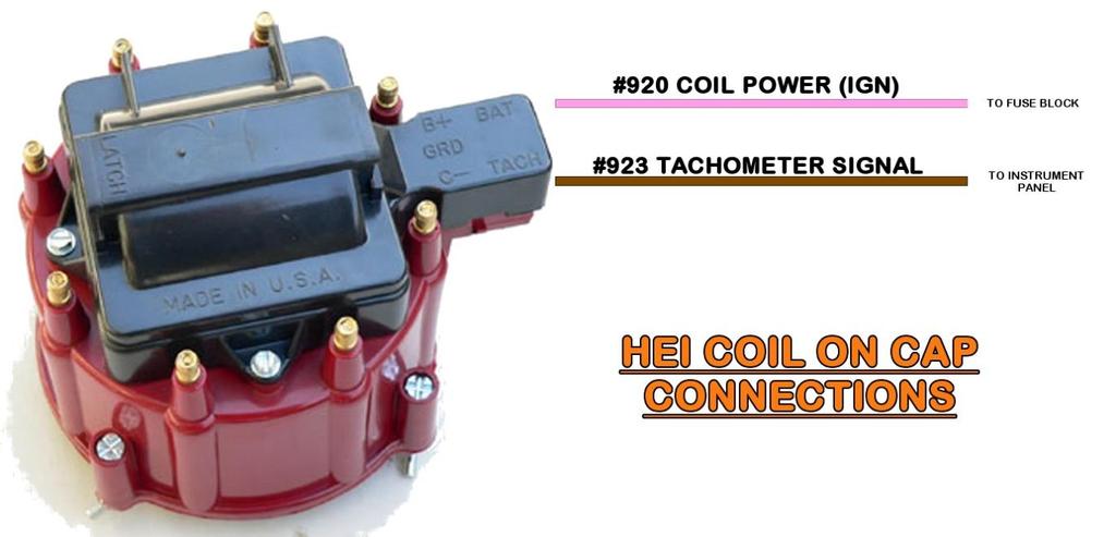
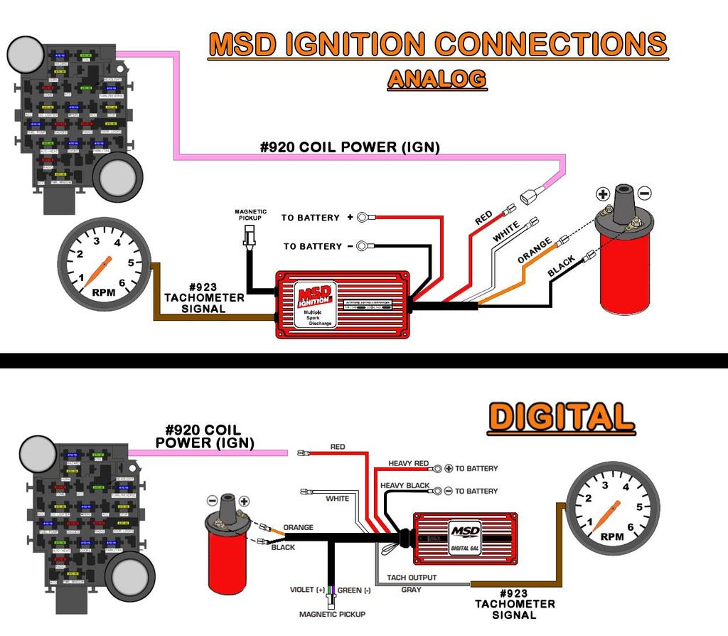
65 56
. Locate the bag kit provided with the Painless harness kit labeled ALTERNATOR.")

66 START/CHARGE SECTION The Start/Charge Section is actually 2 sections, Alternator and MIDI, combined with the #919 PURPLE wire from the Engine Section. These four wires connect to the alternator, starter solenoid, and inline MIDI fuse (included with the kit). Locate the bag kit provided with the Painless harness kit labeled ALTERNATOR. This bag kit contains hardware needed to make the appropriate connections to the alternator as well as a covered inline fuse holder. ALTERNATOR The alternator connections vary depending on the alternator your vehicle currently has installed. The alternator may also need to be removed in order to gain access to the connection points. The one connection all alternators have in common is the output post. This sends power from the alternator to the battery. This connection is made using the large gauge RED wire rolled in the kit, it is: RED: 6 gauge wire, with a tag reading #915 ALTERNATOR OUTPUT, this wire provides power from the alternator to the MIDI fuse and from the MIDI fuse to the battery. This wire is not part of the harness but is a separate, rolled piece of wire provided with the kit. When connected, this wire has power at all times from the battery. See Charge/Battery Power Schematic on page 68. Locate the rubber alternator boot and a large, un-insulated ring terminal from the ALTERNATOR bag that has the right size opening for your alternator post. A piece of the provided red heat shrink may be used along with the boot to secure the terminal (or just by itself over the terminal crimp if the alternator boot is not desired). 57


67 If the rubber boot is being used, the end will need to be cut, as shown in the photo to the right, to allow the large gauge wire to pass through. Slide the heat shrink onto the #915 wire, followed by the rubber boot. A very small amount of lubricant such as WD-40 may be applied on the inside of the rubber boot to allow the boot to slide down the wire easier. With the boot on, strip about 3 8 of insulation from the charge wire and crimp the ring terminal on. You can use a hammer crimper if your hand crimper will not accept this large gauge wire/terminal. Connect this wire to the B+/Output stud on the alternator. Once the nut on the output post stud has been tightened, slide the boot over the nut and ring terminal installed on the alternator. If your vehicle has an aftermarket, ONE WIRE ALTERNATOR, meaning it does not require a switched 12v source or regulator connections, or if the Painless or other aftermarket fuel injection harness you are using has an alternator connector, then this output wire is the only wire used in this section at the alternator. Locate the 2 wires intended for alternator regulator connections; they will be grouped together in the Alternator Section. These wires are: RED: 16 gauge wire, printed [ALTERNATOR] #995 REGULATOR POWER (BATTERY), this is the sense wire, it provides a battery power source, or voltage sense, that all voltage regulators require. This wire has power at all times and comes from the large battery supply splice in the harness. This wire will not be needed if you have a one wire alternator or a GM CS series alternator. See the various alternator illustrations on pages 60, 61, & 63 and the Charge/Battery Power Schematic on page 68. WHITE: 14 gauge wire, printed [ALTERNATOR] #914 ALTERNATOR EXCITOR POWER, this wire runs from the regulator to the bulkhead where it connects to the charge indicator light wire, or connected to the other #914 at the Instrument panel, and has switched ignition power from the fuse block. This wire will not be needed if you have a one wire alternator. 58


68 If you have a one wire alternator, and only if you have a one wire alternator, you need to insulate the ends of these wires and stow them in the harness, THEY ARE POWER WIRES. #995 may also be connected to the output post of the alternator to avoid removing it from the harness since this wire goes into the big battery power splice. The remaining alternator connections vary based on which alternator is being used. Choose the alternator that best represents the alternator found on your vehicle from those on the next few pages. Then, follow the instructions provided for your particular alternator. GENERAL MOTORS SI SERIES ALTERNATORS The 10-SI and 12-SI alternators are easy to identify. They have an external fan behind the pulley (the 12-SI has enclosed style fan blades) and a 2-pin connection. This 2-pin connection is circled on the second example in the image above. These are also commonly referred to as Delco or Delcotron alternators. The two wires, RED #995 REGULATOR POWER (BAT) and WHITE #914 ALTERNATOR EXCITOR POWER, connect to the two posts on the back edge of the alternator. Route the two wires to the numbered 1 & 2 terminals on the alternator and cut to length. Strip ¼ of insulation from both wires. A factory style connector and terminals, seen in the photo to the right, are provided in the ALTERNATOR bag. Crimp a terminal onto each of the two wires. Insert the wires into the connector as shown in the diagram below. When terminal pin-out is complete, plug the connector into the alternator. If you experience engine run-on during testing. This is caused when the alternator back feeds voltage down the #914 wire after the key has been turned off. This allows the ignition system to still function causing the engine to continue running even though the key is turned off or even removed from the ignition. The #914 is tied to the Accessory side of the fuse block, so this should not happen. However, if this should happen, unplug the alternator connector to shut the engine off. If you experience this, a remedy has been provided. 59


69 As shown in the photo on the previous page and diagram below, a diode, splices and heat shrink are provided. If engine run-on occurs, simply install the diode as shown. When the diode is installed inline of the #914 wire with the stripe towards the alternator it lets current flow towards the alternator, but not away from the alternator back-feeding the ignition system, thus fixing the run-on issue. GENERAL MOTORS CS-130 SERIES ALTERNATORS The CS-130, CS-121, and CS-144 alternators closely resemble the SI series alternators. They have an external fan behind the pulley and, generally, a plastic casing on the side and back. These alternators have a 4-pin, sealed connector, shown in the photo below and circled in the image above. The regulator will be marked P, L, S, F. This type of alternator was used on GM TPI and LT1 fuel injected engines among other late 1980s to mid-1990s GM vehicles. The two wires RED #995 REGULATOR BATTERY POWER and WHITE #914 ALTERNATOR EXCITOR POWER, connect to the regulator on the back of the alternator. Route the two wires to the connector on the alternator and cut to length. Strip ¼ of insulation from both wires. The factory 4-pin alternator connector from a factory GM harness or a CS-130 pigtail purchased from Painless (part #30707; see photo to the right), is needed. It is not included with this Painless chassis harness. 60


70 The CS-130 alternator requires a resistance on the WHITE #914 wire. Without this resistance, the regulator on the alternator will burn up. A resistor, splices, and heat shrink, seen below, are provided in the ALTERNATOR bag kit. The resistor* will simply need to be installed inline on the #914 wire as shown in the diagram on the next page. *In factory applications where this alternator was used, a charge indicator light created the necessary resistance. For those with an instrument panel with a charge indicator light, the resistor is not needed. Use 2 of the splices and heat shrink provided in the ALTERNATOR bag kit to splice the CS-130 pigtail to the #914 and #995 wires according to the diagram below. 61


71 GENERAL MOTORS CS-130D SERIES ALTERNATORS The CS-130D can be spotted by the lack of an external fan behind the pulley. These alternators have an internal fan and a plastic casing on the back. These alternators have an elongated, oval, 4-pin, sealed connector, seen circled in the image above. The regulator will be marked P, L, I, S. This type of alternator was used on many engines, including the GM LS series, Vortec, and Gen. III Vortec truck fuel injected engines. There are two wires in the Alternator Section: RED #995 REGULATOR BATTERY POWER and WHITE #914 ALTERNATOR EXCITOR POWER. For the CS-130D alternator, only the WHITE #914 is used. The #995 may be connected to the alternator output post or removed from the harness. Route the WHITE #914 to the connector on the alternator and cut to length. Strip ¼ of insulation. The factory, 4-pin alternator connector from a factory GM harness or a CS-130D pigtail purchased from Painless (part #30705; see photo), needs to be used. The CS-130D alternator requires a switched power source to pin I of the regulator and a resisted power source on the wire going to pin L of the regulator. Without this resistance, the regulator on the alternator will burn up. A resistor, splices, and heat shrink, seen on page 61, are provided in the ALTERNATOR bag kit. The resistor simply needs to be installed inline on the pin L wire, #914, as shown in the diagrams on the next page. In factory applications where this alternator was used, a charge indicator light created the necessary resistance. For those with an instrument panel with a charge indicator light, the resistor is not needed. Using a splice and heat shrink provided in the ALTERNATOR bag kit, splice the CS- 130D pigtail to the WHITE #914 wire according to one of the diagrams on the next page. 62

72 Both diagrams accomplish the same task: they use the WHITE #914 ALTERNATOR EXCITOR POWER wire to provide a switched power source and a resisted power source to the 2 wires of a CS-130D alternator pigtail/connector when a charge indicator light is NOT being used. Pick the method that is easiest for you to understand. 63
 self-tapping screws provided. A drill with a ¼ nut driver is required for the mounting screws.")
73 MIDI FUSE A large, inline MIDI fuse is included in the ALTERNATOR bag kit. This inline fuse provides a fused link between the alternator and battery. Find a suitable location to mount the supplied fuse holder using the (2) self-tapping screws provided. A drill with a ¼ nut driver is required for the mounting screws. With the fuse holder now mounted, locate the following two wires: RED: 8 gauge wire, printed [ENGINE SECTION] #916 BATTERY POWER SOURCE (MIDI FUSE), all power sources in this Painless harness originate from this wire. This wire provides battery power to the fuse block, which in turn supplies battery power to the ignition switch, which provides switched power. During normal operation, this wire has constant battery power at all times. RED: 6 gauge wire, rolled separate from the harness, with a tag reading #915 ALTERNATOR OUTPUT, this wire provides power from the alternator to the battery through the MIDI fuse. See Charge / Battery Power Schematic on page 68. The other end of this wire connects to the output post of the alternator. Route the #915 and #916 wires to one side of the fuse holder and cut the wires to length. DO NOT DISCARD THE CUT OFF PORTION OF #

74 The length of excess wire cut from the #915 wire will be used to connect the other side of the fuse to the + side of the vehicle s battery or to the battery post on the starter solenoid. DO NOT CONNECT THE #915 TO THE ACTUAL BATTERY AT THIS TIME. If routed to the starter solenoid, this wire will NOT replace the battery cable needed by the starter from the positive side of the battery to the BAT or (+) post of the starter solenoid. Make connections to both sides of the fuse holder with the large ring terminals with the small, #10 hole provided with the kit. The heat shrink supplied with this kit is intended to cover the crimped end of each of these (2) ring terminals. A schematic showing these connections can be found on page 68. Once you install the ring terminals onto both studs of the fuse holder, the fuse can be installed and everything can be tightened down with the two retaining nuts provided with the fuse holder. Once everything is tightened, the cover can be reinstalled. Depending on how your crimp flares the ring terminal, the cover may or may not need slight trimming in order to snap into place. 65

75 STARTER SOLENOID The connections to the starter solenoid vary depending on your ignition system, the location of a neutral safety/clutch switch, and your connection point on the battery power source for the MIDI fuse. One connection to the starter solenoid all vehicles share is: PURPLE: 12 gauge wire, printed [STARTER SOL.] #919 STARTER SOLENOID (S TERM.), this wire will supply the solenoid with a switched power source from the ignition switch. This power will activate the starter solenoid causing it to turn the engine over for startup. This wire will only have power when the ignition switch is in the START/CRANK position. If you use a transmission mounted Neutral Safety Switch, the PURPLE #919 wire will need to be routed, cut to length, and connected to one side of the neutral safety switch (NSS). The cut off portion of #919 connects to the other side of the NSS and is then routed to the starter. 4L60e/4l80e switch connections can be seen on the next page. Route the PURPLE #919 and the ballast bypass, if needed, to the starter solenoid and cut to length. If the remainder of RED #915 from the MIDI fuse is being connected to the BAT or (+) post of the starter solenoid, it may be routed at this point as well. Also, if you have a truck with a single fuel tank, the PINK #939 will need to route down under the truck with the PURPLE #919 wire. Be sure to keep all wires away from the exhaust manifold or header. A factory wire shield that used bell housing bolts was installed on the factory harness. If your truck still has this in place, Painless recommends cleaning and reusing it. Locate ring terminals and heat shrink from the parts kit that best fit the posts found on the starter solenoid and install onto the wires going to the starter solenoid. Be sure to apply heat to shrink the insulation to protect the crimp. The PURPLE #919 wire will connect to the START or S post on the solenoid and the bypass wire, if needed, will connect to the I or R post of the solenoid. If you are connecting the battery supply from the MIDI fuse to the battery cable/post on the Starter, connect it now. BE SURE THE BATTERY CABLE IS DISCONNECTED FROM THE BATTERY BEFORE MAKING THIS CONNECTION. 4L60e/4L80e Switch The 4L60e/4L80e transmission, from trucks or SUVs, has a factory reverse switch on the shift detent rod located on the driver s side of the transmission. This same switch also has a park/neutral switch incorporated. If you are using one of these switches instead of the factory steering column switches, use the diagrams below to connect the start and reverse wires of the Painless harness to this switch. 66


76 For those using a 4L60e/4L80e transmission switch, a starter relay must be used (not supplied). The switch is not capable of handling the amperage the solenoid requires. A splice to the PURPLE #919 will need to be made to provide power to the switch as well as to the input of the starter relay. The LIGHT GREEN #956 found in the Tail Harness can also be routed through this switch to control the Reverse/Back Up lights. The only modification needed is to connect the wires inside the vehicle together, as seen below. 67
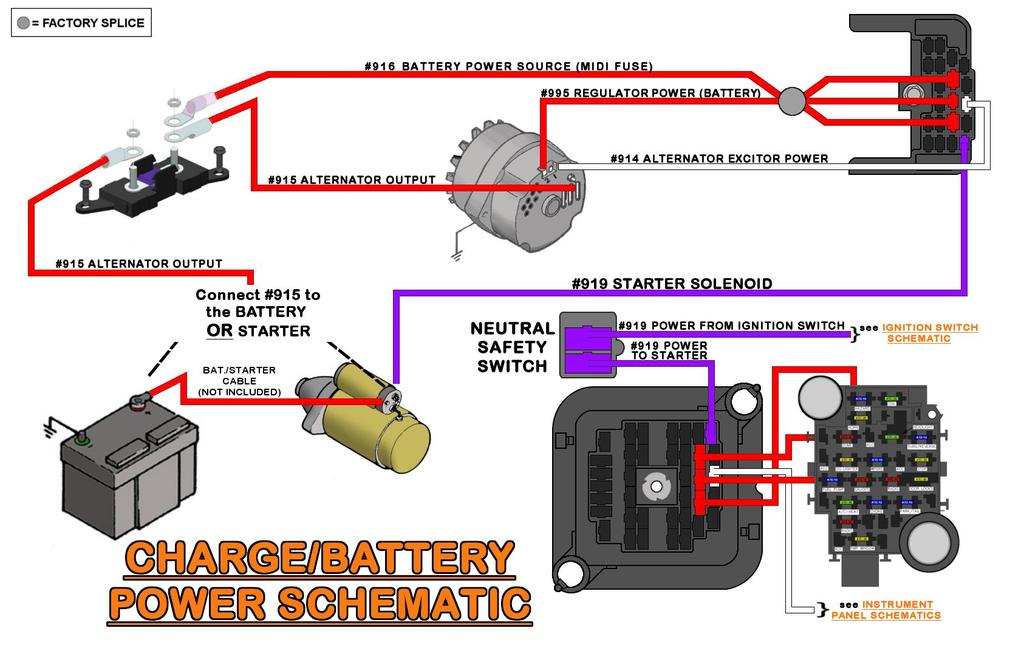
77 68
78 RECONNECTING FACTORY JUNCTION BLOCK The factory firewall mounted junction block provided power for options such as factory A/C, under hood light, camper equipment, power rear window, and other factory accessories, not covered by this Painless harness. A power wire will need to be created and installed, not supplied. Painless recommends using the cut off portion of the 8 gauge RED #916 wire if enough length is available. Otherwise, a length of 10 gauge or larger wire will need to be sourced. Connect a wire from the junction block to the battery side of the midi fuse. This will be the easiest place to source battery power. Please be advised, this will not be fused protected. Painless recommends putting a large, inline fuse, like another MIDI fuse (Painless part #80000), as close to the battery power source as possible. TAIL SECTION The Tail Section is the last group of wires to be connected in the Engine Harness. This section will connect to the driver and passenger side rear turn signals, tail lights, reverse lights, license plate light, and fuel level sending unit. All of the wires found in the Tail Section can be seen in the schematics starting on page 84. Route the wires with the print reading TAIL SECTION to the rear of the vehicle. With the Tail Section being routed under the vehicle and along the frame, it is especially important to cover the wire with some sort of loom. FUEL SYSTEM The factory fuel systems on these trucks came with many different setups. Sending unit connections, factory wire color, and where the factory wires connect will all vary depending on several factors: EFI or non-efi units, a single or dual tanks, and which selector valve you are using. Non-EFI sending units are only responsible for sending a ground signal to the fuel level gauge. The float inside the tank moves up and down with the fuel level in the tank. This raising and lowering of the fuel level moves an arm/contact across a resistor on the sending unit. This sends a resisted signal to the fuel level gauge. The amount of resistance the gauge sees is interpreted as the fuel level on the gauge. In order for the fuel gauge to work properly, the fuel level sending unit s operating range must match the gauge s operating range. These sending units will have a threaded stud on the top of the sender. EFI senders not only handle the fuel level but also have a power wire for the in-tank fuel pump. These sending units will have a small pigtail with a weatherproof, 2-pin connector installed on them. The sending unit must be grounded in order to work properly; Painless does not offer a wire specifically for this. The factory sending unit has a grounding tab with a wire running to the frame. Painless suggests removing the bolt holding this ground and thoroughly cleaning the grounding surface. 69


79 Diagrams are provided on pages 74 & 75 for the proper wiring of the different factory configurations. Read the following instructions for EFI or NON-EFI and SINGLE TANK or DUAL TANK systems to properly connect your sending unit. See page 6 for proper terminal installation instructions. Non-EFI The parts kit provides non-insulated ring terminals and heat shrink to make the connection to the threaded stud on non-efi sending units. If you cut your factory wire, page 17, the bag kit labeled Fuel Sender has inline weatherproof connectors. Pay attention as to which connector the pin and socket terminals belong to in the photo to the right. The male terminal pairs with the female connector and vice versa. Installed a seal and terminal on the wire from the Painless harness as well as the factory cut wire coming from the fuel sending unit. EFI The bag kit labeled Fuel Sender has the mating connector, terminals, and seals for the connector on your sending unit. Use the diagram below and the diagrams for the early and late valves for proper connector pinout. The fuel pump wire in the above drawing will come from the output of a fuel pump relay, typically the 87 pin. DO NOT try to power a high pressure/high volume pump without a relay. Those using a Painless TBI harness, #60101/#60201 this will be a TAN/WHITE wire supplied by that harness. Those using one of our LS harnesses such as #60508 or one of our Gen III Vortec harnesses like #60217, this will be a gray wire supplied by those harnesses. Instructions are provided on page 76 to repurpose one of the un-used dual tank wires to provide a switched ignition power source to a low-pressure fuel pump or to the coil activation side ( 86 pin) of a fuel pump relay. 70
![Single Tank Only one wire from the Painless kit will be needed, it is: PINK: 18 gauge wire, printed [FUEL TANK] #939 TO FUEL SENDING UNIT, this wire sends the ground signal from the fuel level](/docs-images/92/109533477/images/80-0.jpg "sending unit to the fuel level gauge. Route the PINK #939 wire to the fuel level sending unit or to the factory wire you cut as mentioned on page 17. Cut the #939 to length.")
80 Single Tank Only one wire from the Painless kit will be needed, it is: PINK: 18 gauge wire, printed [FUEL TANK] #939 TO FUEL SENDING UNIT, this wire sends the ground signal from the fuel level sending unit to the fuel level gauge. Route the PINK #939 wire to the fuel level sending unit or to the factory wire you cut as mentioned on page 17. Cut the #939 to length. On trucks with a single fuel tank, this wire will route across the firewall with the Engine Section, down under the truck with the starter solenoid wire(s), and down the passenger side frame to the fuel tank. Connect the PINK #939 to the sending unit using the parts the best fit your sending unit type as outlined at the beginning of this FUEL SYSTEM section. Dual Tanks Trucks with dual fuel tanks utilize a fuel selector valve. This valve switches between different feed lines from the tanks to the engine. Later model trucks also switched fuel level signal to the fuel gauge through the valve, while the earlier valve s selector switch on the dash handled gauge functions. It is easy to tell the difference between the two valves. The early version will have a single threaded stud. The later will require a 6 pin connector, supplied with this kit. Two wires can be found in the Tail Section to allow connections for dual tank setups. Also, two additional wires are provided in the Fuel Sender bag to allow connections to the later style valve. These wires are: LIGHT GREEN: 16 gauge wire, printed [FUEL TANK] #997 VALVE ACTIVATION (DUAL TANKS ONLY). This wire will provide different activation sources depending on what valve/switch you are using. On early valves, this wire will provide a switched ignition power source from the selector switch on the dash to the fuel valve. On later valves, it will provide a switched ignition power source and also a ground source depending on what position the dash-mounted selector switch is in. DO NOT GET THIS WIRE CONFUSED WITH THE LIGHT GREEN #956 WIRE OF THE Tail Section. 71
![GREEN: 16 gauge wire, printed [FUEL TANK] #999 TANK SIGNAL (DUAL TANKS ONLY). The function of this wire changes depending on the valve you are using.](/docs-images/92/109533477/images/81-0.jpg "On early valves, this wire provides a fuel level signal to the switch.")
81 GREEN: 16 gauge wire, printed [FUEL TANK] #999 TANK SIGNAL (DUAL TANKS ONLY). The function of this wire changes depending on the valve you are using. On early valves, this wire provides a fuel level signal to the switch. Later valves, it will provide a switched ignition power source and also a ground source depending on what position the dash-mounted selector switch is in. Bagged wires - Only needed with the later style valve PINK/WHITE: 16 gauge wire, printed #994 LEFT FUEL SENDING UNIT TO SELECTOR VALVE, when connected, this wire will provide a fuel level signal from the auxiliary tank on the driver side of the truck to the fuel selector valve. PINK/BLACK: 16 gauge wire, printed #996 RIGHT FUEL SENDING UNIT TO SELECTOR VALVE, when connected, this wire will provide a fuel level signal from the primary tank on the passenger side of the truck to the fuel selector valve. Early Valve If the Tail Section was routed properly, the PINK #939, LIGHT GREEN #997, and GREEN #999 wires should be routed down the driver side frame to the cross brace, about to the middle of the fuel tank. At this point, route the PINK #939 and LIGHT GREEN #997 wires along the cross brace to the passenger side of the vehicle. The GREEN #999 wire will stay on the driver side and connect to the auxiliary tank s sending unit. On the passenger side of the truck, route the LIGHT GREEN #997 to the threaded post on the fuel selector valve. Cut the #997 to length and connect using a ring terminal and heat shrink from the parts kit. Route and connect the PINK #939 to the sending unit using the parts that best fit your sending unit type as outlined at the beginning of this FUEL SYSTEM section. Later Valve If the Tail Section was routed properly, the PINK #939, LIGHT GREEN #997, and GREEN #999 wires should be routed down the driver side frame to the cross brace, about to the middle of the fuel tank. Route these three wires loosely along the cross brace over to the passenger side frame. DO NOT fasten the harness in place at this time as wire(s) will be coming from the fuel selector valve back to the auxiliary tank on the driver side. Route the PINK #939, LIGHT GREEN #997, and GREEN #999 wires to the fuel selector valve. Cut these wires to length. Retain the LIGHT GREEN #997 and GREEN #999 cut off pieces if you have EFI sending units. 72

82 At this time, locate the PINK/WHITE #994 and PINK/BLACK #996 wires from the Fuel Sender bag as well as the seals and terminals shown to the right. Install the seals and terminals onto the PINK #939, LIGHT GREEN #997, and GREEN #999 wires Insert the three wires of the Painless harness and two wires from the bag into the connector using the pinout diagram provided. Plug this connector into the fuel selector valve. With the connector now installed, route the PINK/WHITE #994 from the valve along the cross brace over to the auxiliary sending unit on the driver side frame. This wire should route on top of the wires from the chassis harness that you loosely routed along the cross brace previously. Before properly fastening the wires to the cross brace, see the below information on EFI sending units as you may have an additional wire that needs to route along the brace depending on where you create a splice. If you have EFI sending units, you will need to create some splices. The cut of portions of LIGHT GREEN #997 and GREEN #999 will need to splice into their matching color/#900 series wire. These wires provide power to the fuel valve, and when these wires are spliced to them, the cut of portions of wire will provide a power source to the in-tank fuel pump. See the diagram on the following page for a schematic and visual on this splice. 73

83 Route the PINK/BLACK #996 from the selector valve to the primary, passenger side, sending unit. Make the appropriate connections to your sending units using the parts that best fit your sending unit type as outlined at the beginning of this FUEL SYSTEM section. 74
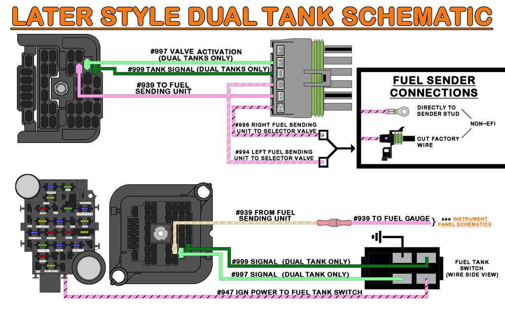
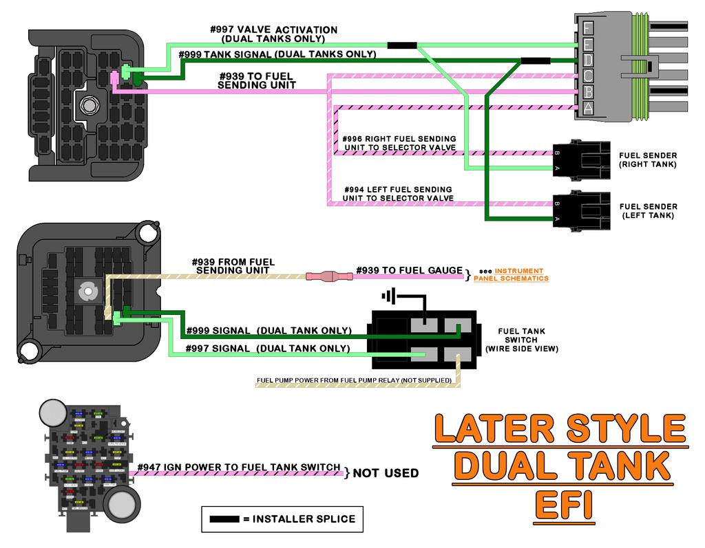
84 75
85 Electric Fuel Pump If your vehicle does not have dual tanks, and you are using an aftermarket electric fuel pump, you can re-purpose one of the provided dual tank wires to provide a power source either to your pump or to the activation coil of a fuel pump relay. Additional instruction, provided in the Tank Selector Switch portion of this manual, will need to be followed as well. Route the GREEN #999 to the fuel pump or fuel pump relay. Connect the #999 wire to the power wire or power connection point of your fuel pump. DO NOT CONNECT THIS WIRE DIRECTLY TO A HIGH PRESSURE/HIGH VOLUME EFI PUMP. EFI fuel pumps with a regulated operating pressure of 40 lbs. or more require a fuel pump relay. If using a relay, connect this wire to the 12v side of the activation coil, pin 86, of a standard automotive relay. Most factory and aftermarket engine control modules will provide a ground signal intended to connect to the ground side of the activation coil, pin 85. Additional instruction, provided in the Fuel Tank Switch portion of this manual on page 103, will need to be followed to create this power supply. At this time you will need to provide a ground wire for the fuel pump. This harness does not provide a ground wire for an electric fuel pump. However, a ground can be easily connected using a ring terminal from the parts kit and a length of scrap wire created during a previous connection. Simply connect the ground or - post/tab/wire of the fuel pump to one of the mounting bolts holding the fuel pump to the frame/body. 76
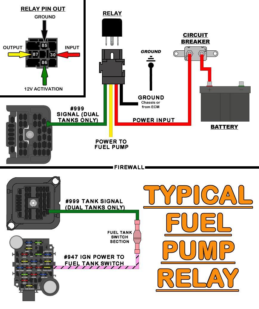
86 77
.")

87 OPTIONAL INLINE CONNECTION FOR TRUCKS (# Sold Separately) An inline connection, similar to the one the factory had, may be added to the Tail Section. This connection would make it easier to remove the bed, as some people do to service the fuel sending unit(s). Painless offers part #70404, which is a four-pin weatherproof connection that makes adding this connection easy. Route the four Tail Section wires all the way down the driver side frame, out to the rear bumper. Cut the Tail Section wires a couple inches past the end of the frame, this will give you enough length to mount the connector to the cross brace (as shown below) once the connectors have been installed. Strip ¼ of insulation from the Tail Section wires on the frame and the lengths of wire that were just cut off. Install the seals and terminals onto the four wires of the Tail Section as well as the cut off lengths. Install the wires into the connectors. The socket (female) terminals will go into the connector with the green seal. Be sure you match color to color when installing the second connector. Plug the two connectors into one another and mount the connector to the frame. The cable tie clips provided with this harness work well for this. Route the cut off lengths of wire to their connection points. 78
88 TAILLIGHT WIRE A single wire has been provided in order to supply power to the marker, tail, and license plate lights. This wire is: BROWN: 16 gauge wire, printed [TAIL SECTION] #929 TO TAIL LIGHT, this is a power wire for the park/marker, tail, and license plate lights. This wire has power anytime the headlight switch is in the Park/Tail Lights ON or Headlights ON position. This wire, along with all the other wires and splices it is associated with, can be seen in the Tail Section Schematics on pages This BROWN #929 wire will need to be modified by either creating a couple splices that run to all the lights, chaining the lights together, or a combination of both. See the image below. Splicing and Chaining are covered in depth on page 136. REVERSE LIGHT WIRE Like the Taillights, there is one wire for both reverse lights that will need to be spliced or chained. LIGHT GREEN: 16 gauge wire, printed [TAIL SECTION] #956 REVERSE LIGHTS, this wire provides power to the reverse or back up lights. This wire receives power from the reverse switch and has power anytime the shifter is in the REVERSE position with the ignition switch in the ON/RUN position. 79

89 Refer to the three diagrams beginning on page 84 and decide which method you d like to implement in order to make your necessary connections. If splicing is preferred, create those splices at this time. Factory style sockets and splices from the parts kit will be needed to make connections. These sockets can be cut from your factory harness, sourced from a local parts store, or will come included in one of the Painless Light Socket Kits (#30350, #30351, #30352, #30353; purchased separately). If cutting sockets from a factory harness, you can leave the ground circuit (the black wires) intact. This Painless harness does not contain grounding wires for these sockets since all factory and aftermarket socket pigtails have ground wires provided. LEFT SIDE ROUTING Route the LIGHT GREEN #956, YELLOW #949, and BROWN #929 wires to the left tail. These wires will route along the back of the vehicle, just above where the bumper mounts, and come up from underneath the vehicle through a hole in the bottom of the taillight recess (see image to the right). Do not make any permanent harness attachments at this time. Depending on how you chose to splice or chain circuits, additional wires, LIGHT GREEN #956 and BROWN #929 may be routed to the right side tail light. LEFT SIDE MARKER LIGHT The left side marker light is the next connection. The marker light is activated by a power source coming from the headlight switch. This light illuminates any time the headlight switch is in the PARK or ON position. The park light requires two wires to work properly: the BROWN #929 power wire and an installer supplied ground. BROWN: 16 gauge wire, printed [TAIL SECTION] #929 TO TAIL LIGHT, this is the power wire for the park or marker light function. This wire has power anytime the headlight switch is in the Park/Tail Lights ON or Headlights ON position. This wire, along with all the other wires and splices it is associated with, can be seen in the Tail Section Schematics starting on page 84. Route the BROWN #929 wire to the marker light and cut to length. Strip ¼ of wire from the BROWN #929 wire and from the wire on the socket. Splice the BROWN #929 wire to the wires on the socket. Connect the other wire to a ground. It does not matter which wire goes where. The other wire will ground to the bolt behind the tail light. The connection of this ground will be made after the tail light and reverse light sockets have been connected as each of those require the use of this same grounding point. 80


90 LEFT TURN - BRAKE LIGHTS / TAILLIGHT To begin making connections to the left turn-brake and tail light socket locate the wires in the tail section dedicated to this function. They are: YELLOW: 16 gauge wire, printed [TAIL SECTION] #949 TO LEFT REAR TURN SIGNAL, this wire provides power to the left turn signal. This wire has power anytime the turn signal is in the down/left position and the ignition switch is in the ON/RUN position. This wire is also the brake light power. The wire has power anytime the brake pedal is pressed or anytime the hazard switch is activated. This wire can be seen in Tail Section Schematics starting on page 84. BROWN: 16 gauge wire, printed [TAIL SECTION] #929 TO TAIL LIGHT, this wire provides the tail light power. This wire receives power from the headlight switch and has power anytime the headlight switch is pulled into the PARK/TAIL LIGHT ON and HEADLIGHT ON positions. This wire can be seen in the Tail Section Schematics starting on page 84. Cut the wires to length and connect them to the appropriate wire on the socket. Consult the manufacturer s instructions if you are using aftermarket assemblies. Splices are provided to make these connections. The black wire on the socket will ground to the bolt behind the tail light. The connection of this ground will be made after the reverse light socket has been connected as it also requires the use of this same grounding point. REVERSE LIGHT Loosely route the LIGHT GREEN #956 reverse light wire to the reverse light. Cut the wire to length and splice it to the appropriate wire on the socket 81

91 GROUND Near the bottom left of the taillight s mounting location is a factory grounding bolt. This point grounded all of the rear socket assemblies. This same grounding point exists on the passenger side as well, though the factory did not install a bolt or star washer. If the appropriate size bolt cannot be found to fit either of these factory grounding points, you could easily create such a point with ring terminals and one of the provided #8 x ½ selftapping screws provided in the parts kit. Connect the light grounds to the factory grounding point at this time. If you are NOT creating your own grounding point on the passenger side, connect an additional 16 gauge or larger wire to this grounding point. This wire will then route to the right side tail light. In our example below, we chose to splice our grounds together to create a clean one wire connection to the grounding point. Also, notice the use of our Classic braid loom. Loom must be used on the Tail Section wires as it does have contact with the body of the vehicle when it passes up into the tail light opening. Chaffing and shorting WILL occur if loom is not used. 82

92 LICENSE PLATE LIGHT The license plate light is the next connection that needs to be made. This light is tied to the rear marker lights and tail lights and will illuminate the license plate when the headlight switch is in the park light ON or headlight ON positions. BROWN: 16 gauge wires, printed [TAIL SECTION] #929 TO TAIL LIGHTS, this is the power wire for the license plate light function. This wire has power anytime the headlight switch is in the park light ON or headlight ON positions. This wire can be seen in the Tail Section Schematics starting on page 84. In most cases, your license plate light will have a socket/bullet terminal connection. Insulated terminals have been provided in the parts kit to connect to these types of plate lights. You can cover the insulated terminal with heat shrink once connected to clean up the look of this connection since colored insulated terminals can often look out of place. RIGHT TURN/ BRAKE/ REVERSE/ MARKER LIGHTS/GROUNDS The connections mentioned above all connect in the same manner as those on the left/driver side. The only difference you will find is the turn signal wire for the right turn signal is a different color than the one used for the left turn signal. The right turn signal will be: GREEN: 16 gauge wire, printed [TAIL SECTION] #948 TO RIGHT REAR TURN SIGNAL, this wire provides power to the right turn signal. This wire has power anytime the turn signal is in the up/right position and the ignition switch is in the ON/RUN position. This wire is also the brake light power and has power anytime the brake pedal is pressed or the hazard switch is activated. This wire can be seen in the Tail Section Schematics starting on page 84. If an aftermarket socket is being used, like those that are included with a Painless Socket kit or those sourced through a local auto parts store, you will notice the socket only being available with a yellow wire. The GREEN #948 wire will connect to the yellow wire of an aftermarket socket. 83
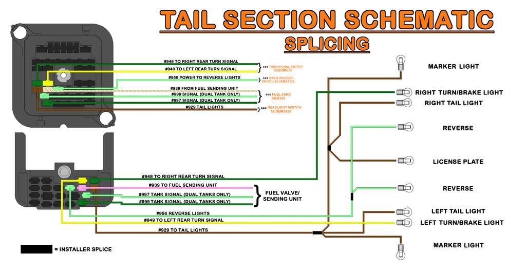
93 84
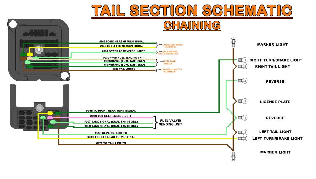
94 85
95 86

96 INTERIOR HARNESS Now that the Engine Harness is wired, move to the interior of the vehicle. This harness should have already been routed and ready to be connected. DIMMER SWITCH The first connection is the group of three wires that belong to the Dimmer Switch Section. These three wires provide power to the headlights for low beam and high beam power. These wires can be seen in the Headlight Dimmer Switch Schematic on page 88. They are: YELLOW: 14 gauge wire, printed [DIMMER SWITCH] #907 DIMMER SWITCH POWER [HEADLIGHT SWITCH], this wire provides power to the dimmer switch from the headlight switch. This wire has power whenever the headlight switch is in the HEADLIGHT ON position. TAN: 14 gauge wire, printed [DIMMER SWITCH] #909 LOW BEAM POWER, this wire provides power from the dimmer switch and into a splice with 2 other wires. The other two wires feed power to each low beam of the headlights, as seen in the Headlight Section Schematics on pages 44 & 45. Once connected, this wire has power when the headlight switch is in the HEADLIGHT ON position and the dimmer switch is in the LOW BEAM position. LIGHT GREEN: 14 gauge wire, printed [DIMMER SWITCH] #908 HIGH BEAM POWER, this wire provides power from the dimmer switch to each high beam of the headlights and to the high beam indicator as seen in the Headlight Section Schematics on pages 44 & 45. Once connected, this wire has power when the headlight switch is in the HEADLIGHT ON position and the dimmer switch is in the HIGH BEAM position. The connection point of these wires depends on the location of the dimmer switch. Most applications have a floor mounted dimmer switch; although, those using a later model GM column may find the dimmer switch on the side of the column. Those with a column mounted dimmer, your switch wires should have been routed with the wiper switch wires on page 18. If not do so now. The wires end in a connector like the one seen to the right. Route the wires to the floor mounted dimmer switch and connect. The three wires should be connected to the dimmer switch as shown in the diagram on the next page. 87

.")
97 EMERGENCY BRAKE SWITCH Locate the wire coming from the top of the fuse block. This connection is for the emergency brake switch that activates the brake indicator light on the dash. For those that are using aftermarket gauges and do not have a brake indicator light, this wire will have no function and can be removed from the harness. This connection will be one wire and will have a connector pre-installed. This wire is: TAN/WHITE: 18-gauge wire, printed #968 TO EMERGENCY BRAKE. This wire sends a ground source to the brake warning light in the dash; this causes the light to turn on when the emergency brake pedal is down (see Instrument Panel Schematic on page 135). Route the TAN/WHITE, #968 wire to the emergency brake switch found next to the driver side kick panel and connect. 88

![Two wires will need to be connected to a chassis ground source to complete the ground circuit, they are: (2) BLACK: 16 gauge, printed [GROUND] #969 TO CHASSIS GROUND.](/docs-images/92/109533477/images/98-1.jpg "When connected to a chassis, these wires will complete the grounding circuit of the interior harness. The factory grounds were found on a buss bar with 6 tabs.")
98 GROUNDS Ground wires have been provided for components such as the gauge cluster, radio, clock, and tachometer. These grounds are provided through splicing and doubling ground wires at connectors and can be seen in the Ground Schematic below. Two wires will need to be connected to a chassis ground source to complete the ground circuit, they are: (2) BLACK: 16 gauge, printed [GROUND] #969 TO CHASSIS GROUND. When connected to a chassis, these wires will complete the grounding circuit of the interior harness. The factory grounds were found on a buss bar with 6 tabs. This buss was located on the same bracket that holds the emergency brake, and can easily be seen through the gauge cluster opening. Factory style terminals and connectors have been provided to allow for proper connection. If you find that the buss bar is missing from your vehicle, the ground wires can be connected to the mounting bolt of the e-brake bracket (seen to the left of the buss bar in the photo on the next page). Ring terminals and heat shrink from the parts kit will be needed. 89


99 LEFT/DRIVER DOOR JAMB SWITCH The door jamb switches provide a ground activation for the courtesy lights and dome light. When the door is opened, the plunger on the switch extends out as it is no longer being pushed in by the door. When the plunger extends, the contact point on the back of the switch makes contact with the body of the switch, which is grounded through the mounting into the metal door jamb. This grounding gives the wire attached to the switch a ground source which will then cause the interior lights to turn on. Locate the single wire of the Jamb Switch Section intended for the driver door jamb switch. It is: WHITE: 18 gauge wire, printed [DRIVER JAMB SWITCH] #961 DOME/COURTESY LIGHT ACTIVATION, this wire is spliced to other white wires leading to the dome light, courtesy light, headlight switch, and the passenger side door jamb switch. This wire is grounded anytime either door is opened, or when the headlight switch knob is rotated to the DOME LIGHT ON position. This wire can be seen in the Dome / Courtesy Light Schematic on page 106. Locate the supplied grommets provided for jamb switch pass through. These grommets will fill the pass-through of the inner fender. Along with these grommets, you will need a piece of scrap wire, at least 24, from a previous connection. 1. You will need to create a fish wire to get the WHITE #961through the empty jamb switch hole. To do so, insert the scrap wire through the jamb switch hole and up to the larger hole behind the dash. 90


100 2. With the wire now running through the door jamb, thread one of the grommets onto the wire, and seat it into the hole. Notice there are two holes, a larger hole giving you access to a smaller hole, and this grommet will fit the smaller hole. This was not done before to make it easier to get the wire through the hole. 3. Loop the end of the fish wire nearest the grommet with the end of WHITE #961. Make sure that neither the fish wire nor WHITE #961 is wrapped around the dash or emergency brake. Also make sure you tape the ends of the wire as shown. This will prevent wires catching anything as you pull the wire through the door jamb. 4. Carefully pull the fish wire coming from the jamb switch hole, doing so will pull the White #961 through the grommet down into the door jamb. Slowly feed the fish wire and the WHITE #961 as you pull. 5. Once the WHITE #961 is through the jamb switch hole, remove the tape and save the scrap piece of wire as you will need it for the passenger side jamb switch wire as well. Locate the appropriate insulated terminal from the parts kit and install. 91


101 Some jamb switches will have a single socket on them and will require an insulated pin terminal, while other jamb switches have 2 small tabs which will require a small insulated spade terminal. Please note, on jamb switches with two tabs, only one of the tabs will be connected. The other tab was for a Key in the ignition buzzer, it is not supported with this harness and it will not matter which tab the #961 connects to. A/C-HEAT As previously mentioned, this harness does not include any wiring for the factory air conditioning. Your original harness or Painless A/C harness #30902 must be used. This chassis harness does include wiring for the blower motor and blower motor resistor for vehicles with heat only systems. The harness provides a power wire that plugs into a an original, factory harness or Painless #30902, and the heater only sub harness provided with this kit. This wire is: BROWN: 14 gauge wire, printed, [ACC. SECTION] #904 HEATER-A/C POWER, this wire comes from the 30 amp A/C-HEAT fuse and provides a switched ignition power source for a factory or aftermarket A/C system. This wire has a single-pin white connector pre-installed FACTORY HEATER OR A/C HARNESS Locate the inline connector on the factory heat or A/C harness, it will be a single-pin connector with a BROWN wire several inches away from the blower switch connection. Plug the BROWN #904 power wire into this connector on the factory harness. If you find the connector on your factory harness does not match the connector on the Painless harness, remove the connector from the factory harness and replace it with one of the single-pin black connectors and terminals from the parts kit. PAINLESS #30902 A/C HARNESS The BROWN #904 wire will plug directly into the brown wire found on the A/C harness. Follow the instructions that come with the Painless #30902 harness as different pigtails supplied with that kit will be needed for the different switches and resistors. 92
102 HEATER ONLY SYSTEMS There were 2 different blower switches and 2 different resistors used during the production of these trucks; thus, resulting in 4 different ways your heater only system can be wired. Locate the supplied heater only bag. This bag will contain a sub harness, 2 pigtails, and 4 connectors. This harness will allow a connection between the blower switch mounted on the dash and the motor and resistor located in the engine compartment on the passenger side of the firewall. This harness is intended to pass through the factory hole in the firewall. Please note: The connector needed for the 3-pin resistor has been discontinued, (3) single-pin connectors have been provided instead. Using the diagrams below, identify which blower switch/resistor combo you have. And install the appropriate resistor connector(s) onto the pre-installed terminals of the heater harness. If your system does not require the use of the LIGHT GREEN wire, it may be removed from the harness. At the glove box opening, route the white 6-pin connector of the heater harness behind the dash up and over towards the blower switch panel. Locate the correct blower switch connector pigtail from the parts kit and install it onto the heater harness. Plug the heater harness onto the blower switch. Route the resistor connector(s) and the single-pin blower motor connector through the firewall hole. From the engine compartment pull the heater harness through the hole and seat the grommet that is pre-installed on the harness. Connect the harness to the blower motor resistor. If you have a 3-terminal resistor, the diagram below shows which wire goes where. Plug the ORANGE wire with the pre-installed single-pin connector onto the tab of the blower motor. The ORANGE wire will provide power to the blower motor from the resistor when in low or medium speeds and directly from the blower switch when Hi is selected. A ground wire is not provided as it is a separate wire coming off the blower motor to the firewall. Inspect your ground wire and its mounting point for a good connection. 93
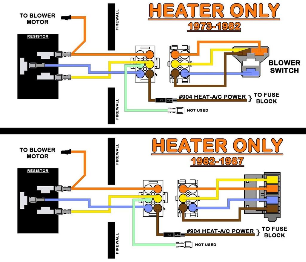
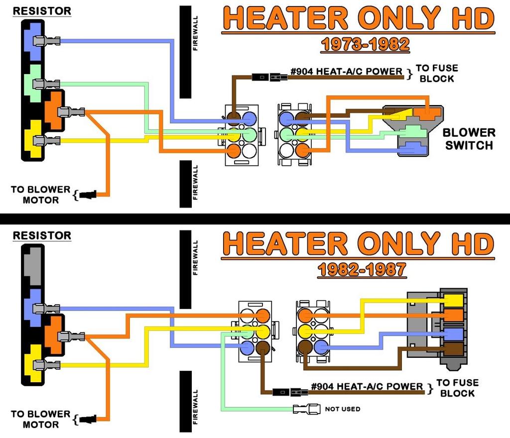
103 94

104 A/C-HEAT PANEL LIGHT A light socket has been pre-installed on this chassis harness to provide a backlight to the factory A/C-Heater panel. A bulb for this socket can be found online or at your local parts store using either part #1893 and/or #1895, both bulbs will work in this socket. Two wires from the Painless harness are connected to this socket, they are: GRAY: 18-gauge wire, printed [A/C PANEL] #930 PANEL LIGHT POWER. This wire provides power to the light socket and will have power whenever the park/tail lights and gauge backlighting are turned on. This wire comes from a splice that distributes power from the headlight switch and can be seen in the AC, Radio. And Accessories Schematic on page 96. BLACK: 18-gauge wire, printed [A/C PANEL LIGHT] #969 LIGHT GROUND. This wire provides a ground source for the light and comes from a splice that is tied to the interior ground wire. This panel light ground and the other interior ground wires and splices, can be seen in the Ground Schematic on page 89. Insert the socket, with a bulb installed, into the panel lamp hole on the back of the A/C and/or heat control panel. Fig. 188 AFTERMARKET A/C If you are using an aftermarket A/C system, which may require a power source for illumination to the panel, the GRAY #930 wire can be used for this purpose. Remove the socket from the Painless harness and connect the GRAY #930 wire to the illumination wire coming from the A/C control panel. The black ground wire is not used. 95

105 RADIO & ACCESSORIES This Painless harness includes provisions for several accessory components which may or may not be used on your particular install. Below, you will find information about each of these accessories and the wires provided in this harness to connect them. 96

106 ACCESSORY SECTION The Accessory Section of the Painless harness consists of 5 wires for various accessory applications. The locations of all of these components vary from vehicle to vehicle, so no specific routing instructions can be given. Any unused power wires MUST have the end of the wire insulated. Cigarette Lighter / Power Port The Cigarette Lighter/Power Port connection on the Painless harness is set up for a universal application since most sockets have been replaced by aftermarket sockets. Typically, the cigarette lighter is more commonly used as a power port to charge and run electronic components requiring a 12vDC power source. TAN: 14 gauge wire, printed, [ACC. SECTION] #903 CIGARETTE LIGHTER POWER (BAT), this wire comes from the 20 amp CIG LIGHTER fuse and provides a battery power source to a cigarette light/power port. Route the TAN #903 wire to the cigarette lighter/power port. Cut the wire to length and connect according to one of the following options (see the clock notation below before doing any termination): 97 o Ring terminals and insulated socket style terminals, as well as a factory style, black, single-pin connector and terminals are provided in the parts kit to connect universal aftermarket and/or factory lighters/power ports. o For those with a factory socket requiring a large round connector that snaps to the back, you will have to cut the connector from your factory harness. Leave 3 or 4 of wire to create a pigtail and splice it to the TAN #903 wire on the Painless harness. Splices have been provided in the parts kit. Accessory Wires GRAY/WHITE: 16 gauge wire, printed [ACCESSORY SECTION] #906 ACCESSORY POWER (IGN.), this wire provides a switched ignition power source from the 15 amp CHOKE fuse. GRAY/WHITE: 16 gauge wire, printed [ACCESSORY SECTION] #901 ACC. OUTPUT TO ENG. HARNESS. This wire goes through the bulkhead and connects to the #901 accessory wire in the Headlight Section under the hood. There are numerous ways these two wires can be used and connected. If an accessory is to be powered or an accessory relay, like a cooling fan or driving/fog light relay, is to be installed, choose the best connection method according to the instructions and diagrams that follow. This wire can only be used to power an accessory up to 10 amps when an electric choke is also connected.

107 If there is no need for an extra switched ignition power source at this time, simply insulate the #906 wire with an insulated terminal from the parts kit. #901 can remain openended or removed from the harness Powering a Component The component you are powering, plus the other circuits tied to the CHOKE fuse, must not exceed 20 amps. The fuse found pre-installed on the fuse block for the CHOKE circuit is 15 amps and may be swapped out in favor of a larger 20 amp fuse if the need arises. DO NOT EXCEED A 15 AMP FUSE as the wires on these circuits are only 16 and 18 gauge wires. The connection for powering an aftermarket component will depend on where the component is located. If the component is located within reach of the #906 wire on the inside of the vehicle, wire #901 will not be used. Route wire #906 to the component to be powered. Use male and female disconnect terminals to connect the #906 wire to the terminal/stud/wire on the component requiring a switched ignition power source. 98

108 If a component is located in the engine compartment, connect #906 and #901 together. This will supply power to the #901 accessory wire in the Headlight Section of the engine harness. Relays Those needing to activate relays have two options: power-activate the relay or ground activate the relay. The difference will determine how the #906 and #901 wires are wired. Refer to the RELAY& SWITCHES section at the front of this manual for a better understanding of 12v and ground activating. If you are ground activating a relay, such as in the case of a cooling fan using a thermostatic switch (coolant temp switch), or activating using a ground output from a fuel injection ECM, connect according to the instructions below. In these instances, pin 85 of the relay will connect to the ground activation source, the coolant temp switch, or ECM ground activation wire. The instructions below also work when installing a relay that will operate an electric fuel pump, water pump, or some other component that you want to activate anytime the key is in the ON/RUN position. In these instances, pin 85 of the relay will connect to chassis ground. If the relay is to be installed in the engine compartment: Connect #906 and #901 together using a red splice from the parts kit. This will supply power from the fuse block, through the #906 wire, to the #901 wire going to the bulkhead. Then, from the bulkhead in the engine compartment, to the #901 wire in the engine harness. 99

109 If the relay is to be installed on the interior, not recommended for cooling fan relays: Connect the #906 to the 86 pin of the relay. This will be the only wire supplied by the Painless harness for relay connection. See the second ACC Relay Activation diagram on the bottom of the following page for the proper connection of the remaining relay pins. See the relay section of our website to select the appropriate relay kit(s) for your application: 100

110 If you are installing a relay that will operate an electric fuel pump, water pump, fog lights, or some other component that you want to activate with a toggle/rocker switch, then: Connect #906 to the center post of the switch. This will supply power from the fuse block, through the #906 wire, to the switch. Connect #901 to the output side of the switch. This will send power from the switch to the bulkhead and from the bulkhead in the engine compartment, to the #901 wire in the ACC SECTION of the engine harness. Power Windows & Power Locks Two accessory wires have been provided in the Accessory Section for those with power windows and/or power locks. These wires are: PINK: 14 gauge wire, printed [ACCESSORY SECTION] #912 POWER WINDOW POWER (IGN), this wire provides a switched ignition power source for power windows from the 20 amp PWR WINDOW fuse. This wire provides power to the windows any time the ignition key is in the ACCESSORY or ON/RUN position. ORANGE/BLACK: 14 gauge wire, printed [ACCESSORY SECTION] #913 DOOR LOCK POWER (BAT), this wire provides a battery power source, from the 20 amp DOOR LOCKS fuse. This wire provides constant battery power for door locks. For those installing aftermarket power locks, connect the ORANGE/BLACK #913 wire to the wire or switch/relay input that requires a fused battery power source. For those installing aftermarket power windows, connect the PINK #912 wire to the wire or switch/relay input that requires a fused switched ignition power source. 101


111 For those reusing the factory power lock/power window harness, the fuse block connectors on your factory harness can plug into the front of the Painless fuse block. These accessory ports are powered by the LOCK and WINDOW fuses RADIO The radio connection on the Painless harness is set up for a universal application. This means the wire colors used by Painless reflect the colors most aftermarket companies use on radios/head units manufactured today. The Painless harness includes 5 wires dedicated for a connection to the radio. These wires are: YELLOW: 18 gauge wire, printed [RADIO SECTION] #940 RADIO POWER (BAT), this wire provides the radio a battery power source that allows the time and radio presets to remain every time the ignition is turned off. This wire comes from the fuse block and can be seen in the A/C, Radio, & Accessory Schematic on page 96. RED: 18 gauge wire, printed [RADIO SECTION] #941 RADIO POWER (IGN), this wire provides the radio with ignition-switched power for operation. This wire has power when the ignition switch is in the ACCESSORY and ON/RUN positions. This wire comes from the 10 amp RADIO fuse of the fuse block and can be seen in the A/C, Radio, & Accessory Schematic on page 96. GRAY: 18 gauge wire, printed [RADIO SECTION] #930 DIM/ BACKLIGHT POWER, this wire provides a power signal to the radio to dim the backlighting/display during low light conditions. On older radios, this power source illuminates the backlighting. This wire has power anytime the headlight switch is in the Park/Tail Lights ON or Headlights ON position. This wire/splice can be seen in the A/C, Radio, & Accessory Schematic on page 96. BLUE: 18 gauge wire, printed [DOME SECTION] #998 AMP TURN ON [RADIO SECTION], this wire provides switched power from the head unit to an amplifier. You will only need this wire if you have an audio amplifier. BLACK: 18 gauge wire, printed [RADIO] #969 GROUND. This wire is part of the separate ground harness and provides a ground to the radio. 102

112 If you use an aftermarket radio, refer to the manufacturer s installation guide for proper connection. Splices and quick disconnect terminals are provided in the parts kit. If your radio/head unit does not have a Remote Turn On output, connect the BLUE #998 wire with the RED #941 wire to provide switched ignition power to the amplifier. Be aware that this will provide power to the amplifier any time the ignition key is in the ACCESSORY or ON/RUN position. If you are using a factory radio, a factory schematic for the vehicle it came out of is needed to identify the connections to the radio. Many older, factory radios require one power source. Painless recommends connecting the RED #941 wire to the radio in these circumstances so that the radio will only operate when the ignition switch is in the ACCESSORY or ON/RUN position. This prevents the radio from draining the battery if it is accidentally left on. FUEL TANK SWITCH This group of wires is for those with a dash mounted fuel tank switch. This switch sends power to the fuel select valve which then controls which fuel tank supplies fuel to the motor. If you do not have a dual tank system, the following information will still be useful as there are other things that can be and need to be done with these wires. The fuel tank switch wires can all be seen in the Dual Tank Schematics on pages 74 75, these wires are: PINK/BLACK: 14 gauge wire, printed [FUEL TANK SWITCH] #947 IGN POWER TO FUEL TANK SWITCH, this wire supplies power from the 15 amp FUEL PUMP fuse to the fuel tank switch. This wire will have power when the ignition is in the ON/Run and CRANK positions. PINK: 18 gauge wire, printed [INSTRUMENT PANEL] #939 TO FUEL GAUGE [FUEL TANK SWITCH], this wire carries the fuel level signal from the tank switch section to the instrument panel. TAN/WHT: 18 gauge wire, printed [FUEL TANK SWITCH] #939 FROM FUEL SENDING UNIT, this wire comes from the bulkhead and delivers the fuel level signal from the fuel sending unit(s). LT.GRN: 16 gauge wire, printed [FUEL TANK SWITCH] #997 SIGNAL (DUAL TANKS ONLY), this wire carries various signals to/from the dual tank system based on the use of an early or later style switch as well as the switch position. GREEN: 16 gauge wire, printed [FUEL TANK SWITCH] #999 SIGNAL (DUAL TANKS ONLY), this wire carries various signals to/from the dual tank system based on the use of an early or later style switch as well as the switch position. 103

113 Out of the box, this Painless chassis harness comes with the PINK and TAN/WHITE #939 wires connected together. These wires must remain connected UNLESS you are using an early style switch and fuel valve. Each type of switch and valve were shown and described previously in this manual on page 70. If these wires are disconnected and not re-connected to the early style switch, your fuel gauge will NOT work. Your factory tank switch must be re-used. Factory style terminals have been provided. If you do not have a factory connector, insulated terminals from the parts kit can be used. Those with a later style switch, your factory ground wire will also need to be re-used. Using the pinouts below, connect the fuel tank switch wires to the fuel tank switch. 104

 ORANGE: 18 gauge, printed [COURTESY LIGHT] #971 COURTESY LIGHT POWER, this wire provides power from the")
114 COURTESY LIGHTS Two sockets are pre-installed on the harness. These connections allow the driver side and passenger side under the dash and floorboard of the vehicle to be illuminated any time a door is opened or when the headlight switch is activating the dome light. These sockets can use either a 63 or 67 series bulb, found at any auto parts store. These wires can be seen in the Dome/Courtesy Light Schematic on page 106, these wire are: (2) ORANGE: 18 gauge, printed [COURTESY LIGHT] #971 COURTESY LIGHT POWER, this wire provides power from the 10 amp DOME fuse on the fuse block. This fuse is battery powered and has power at all times. (2) WHITE: 18 gauge, printed [COURTESY LIGHT] #961 COURTESY LIGHT GROUND, this is the ground wire that activates the courtesy light. When this wire is grounded, it completes the voltage path and causes the light to illuminate. This ground comes from either of the door jamb switches, if the door is opened, or the headlight switch when it is turned to the DOME LIGHT ON position. There are 2 different lengths to these sockets, the one that is 12 shorter, will illuminate the driver side. The shorter socket will have 4 wires in the socket as two of these wires jumper to the longer passenger side socket Locate suitable mounting locations on the bottom of the dash. You can find preexisting factory holes these sockets can mount to. Mount the sockets at this time. The light socket has a small hole in a mounting tab to allow mounting. This kit provides self-tapping screws to hold the sockets. Washers or screws with larger heads may be needed if your pre-existing holes are too large. Factory screws may also be re-used. PASSENGER SIDE DOOR JAMB SWITCH The passenger side door jamb switch is the last connection on the passenger side of the vehicle s interior. Connect this single wire in the same manner the driver side was connected on page
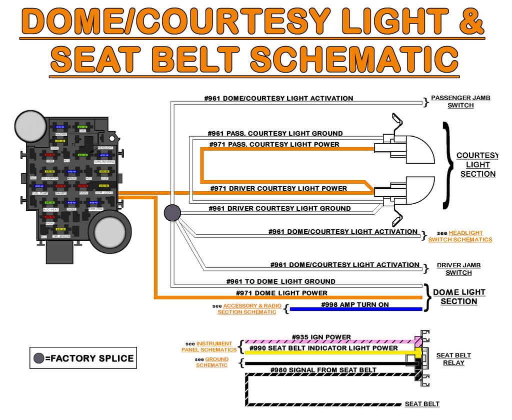
115 106
116 HEADLIGHT SWITCH The headlight switch s connections send power to the headlights, front park/marker lights, rear tail lights, and component backlighting, such as gauges and the radio. These wires can be seen in the Headlight Switch & Dimmer Switch Schematic on the next page. These wires come with a connector pre-installed; they are: ORANGE: 14 gauge wire, printed [HEADLIGHT SWITCH] #959 HEADLIGHT SWITCH POWER (BAT), this wire supplies constant battery power for the park/tail lights as well as for the gauge backlighting. This wire comes from the 15 amp PARK/TAIL fuse on the fuse block. RED: 12 gauge wire, printed [HEADLIGHT SWITCH] #928 HEADLIGHT SWITCH POWER (BAT), this wire provides constant battery power to the headlight switch for headlight operation. This wire comes from the 30 amp HEADLIGHT fuse on the fuse block. BROWN: 16 gauge wire, printed [HEADLIGHT SWITCH] #927 FRONT PARK LIGHTS, this wire supplies power to the park lights. This wire has constant battery power any time the headlight switch knob is pulled to Park Light ON and, depending on your switch, the Headlight ON position. BROWN: 16 gauge wire, printed [HEADLIGHT SWITCH] #929 TAIL LIGHTS, this wire supplies power to the tail lights. This wire has constant battery power any time the headlight switch knob is pulled to both the park light ON and headlight ON positions. YELLOW: 14 gauge wire, printed [DIMMER SWITCH] #907 DIMMER SWITCH POWER [HEADLIGHT SWITCH], this wire supplies power to the dimmer switch for headlight operation. This wire has constant battery power any time the headlight switch knob is pulled to the headlight ON position. GRAY: 18 gauge wire, printed [HEADLIGHT SWITCH] #930 GAUGE LIGHTING, this wire provides power to the gauge lights. This wire should have constant battery power any time the headlight switch knob is pulled to both the park light ON and headlight ON positions. GRAY: 18 gauge wire, NOT PRINTED. This wire provides power to the wiper switch light on dash-mounted wiper switches. WHITE: 18 gauge wire, printed [HEADLIGHT SWITCH] #961 DOME/COURTESY LIGHT ACTIVATION, this wire provides a ground source for the interior dome/courtesy lights. Those with roof mounted clearance lights, connect the black wire that was removed from your factory harness into the connector cavity next to the two gray wires. The locking tang of the terminal may need to be gently pried back out to lock into the connector. Route the wires to the headlight switch and connect. Make sure the connector goes on straight as the tabs of the headlight switch can bend. 107
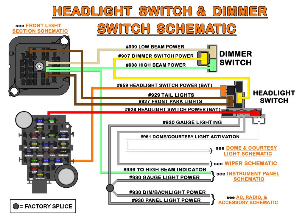
117 108
118 WIPER SWITCH The Wiper Switch Section consists of 6 wires that provide power, ground, and outputs for the wiper switch leading to both the motor and pump. GRAY: 18 gauge wire, NOT PRINTED. This wire provides power to the wiper switch light on the dash mounted wiper switches. BLACK: 16 gauge wire, printed [WIPER SWITCH] #969 GROUND. This wire will provide a ground source for the switch as well as the panel light found on most trucks The following wires all provide ground signals out to the wiper motor and washer pump: PURPLE: 18 gauge wire, printed [WIPER SWITCH] #977 HIGH SPEED. GRAY/WHITE: 18 gauge wire, printed [WIPER SWITCH] #978 LOW SPEED BLACK/BLUE: 18 gauge wire, printed [WIPER SWITCH] #980 PARK PINK: 18 gauge wire, printed [WIPER SWITCH] #983 WASHER ACTIVATION. As mentioned in the pre-installation steps on page 19, those of you with a switch will need to re-use the connector from your factory harness. The terminals preinstalled on the harness are for those with a switch. 109


119 SWITCHES Cut the pre-installed terminals from the wiper switch wires. Cut these wires as close to the terminal as possible to ensure you have adequate length to reach the wiper switch. A 2-pin connector and single-pin connectors have been supplied in the parts kit, or you can also re-use your factory connector. From the diagrams shown on the next page, identify which wires you will be using switches will not need the BLACK/BLUE #980, BLACK #969 or the GRAY, unprinted, wires switches will not need the BLACK/BLUE #980 wire. Strip ¼ of insulation from the wires and install new terminals. Install the supplied 2- pin connector onto the PURPLE #977 and GRAY/WHITE #978 wires. Use a single pin connector to make the remaining connections. Those with a switch take notice that the factory light socket will need to be reused. Splices and heat shrink have been provided. The black ground wire from the socket will need to double up with the BLACK #969 wire on the wiper switch. 110


120 SWITCHES As previously mentioned, the factory wiper switch connector will need to be re-used. Terminals for this connector have been pre-installed on the Painless harness. Those with delay/pulse wipers will need the pulse module and the wiring from the module to the switch. The Painless harness will connect to the module. To remove the terminals from the factory connector the connector s terminal lock will need to be pried up. The locking tang of the factory terminals will need to be depressed to remove the terminal. This terminal locking tang will be on the opposite side of the connector terminal lock. Be careful not to damage the connector; the terminals on the Painless harness will need to lock into place. Using the picture below, insert the wiper switch wires of the Painless harness into your connector. The terminals will only fit into the connector one way. Pay close attention to the stripes and print on the wires as not to get the Gray wires and the Black wires mixed up. 111

121 SWITCHES (COLUMN MOUNTED) A connector for your wiper switch has been provided in the parts bag. It is the 2 long, gray, 7-way connector. Using the picture below, insert the wiper switch wires of the Painless harness into the connector. The terminals will only fit into the connector one way. Column mounted switches DO NOT need the unprinted GRAY wire as it provides lighting for a dash mounted switch. Pay close attention to the stripes and print on the wires as not to get the Gray wires and the Black wires mixed up. 112

122 The reverse switch connection provides the backup lights the power they need to illuminate. This switch is a 2-pin, normally open switch that has power coming into one side and out the other to the backup lights. When the shifter is put into the reverse position, contact is made between these 2 pins, closing the switch. This allows power to flow from one pin to another, thus transferring power through the switch out to the backup lamps. The 2 wires provided for this option are: REVERSE SWITCH LIGHT GREEN: 16 gauge wire, printed [REVERSE SWITCH] #958 REVERSE SWITCH POWER (IGN), this wire comes from the 15 amp TURN/REV fuse on the fuse block. This wire is a switched ignition power wire meaning it will only have power when the ignition switch is in the ACCESSORY and ON/RUN positions. LIGHT GREEN: 16 gauge wire, printed [REVERSE SWITCH] #956 POWER TO REVERSE LIGHTS, this wire provides power from the reverse switch to the backup lights in the Tail Section of the Painless harness. On automatic trucks, the reverse switch can be found at the base of the steering column. If you have a manual transmission, the reverse switch is on the transmission. The connector on the LIGHT GREEN #956 and LIGHT GREEN #958 wires will plug into your factory transmission pigtail coming from the firewall. This pigtail should have remained in the truck during the factory harness removal according to the instructions given on page 16. If you are using a reverse switch found on a 4L60E/4L80E or one of the many variants of these transmissions, remove the connector and terminals from the two LIGHT GREEN wires. The wires will need to be spliced together to provide power to the transmission mounted switch which should have been connected on page
 or if the clutch pedal is depressed (manual transmissions).")
123 NEUTRAL SAFETY / CLUTCH SWITCH This switch is a safety device that prevents the vehicle from being started while in gear and causing an unfortunate accident. The purpose of this switch is to only allow the engine to be started when the vehicle is in park or neutral (automatic transmissions) or if the clutch pedal is depressed (manual transmissions). When the transmission is put into park/neutral or the clutch pedal is depressed, contact is made between the 2 pins of the switch, thus closing it. This allows power to flow from one pin to another, transferring power through the switch to the starter solenoid. The neutral safety/clutch switch connection is 2 wires: PURPLE: 12 gauge wire, NOT PRINTED, this wire comes from the ignition switch and only has power when the switch is in the START position. This wire provides power to the neutral safety switch (NSS) from the ignition switch. PURPLE: 12 gauge wire, printed [NSS/REVERSE SWITCH] #919 POWER TO STARTER, this wire provides power from the NSS to the starter solenoid S terminal. This wire can be seen in the Charge / Battery Power Schematic on page 68 and in the Ignition Switch Schematic found on pages 119 If you have an automatic transmission with a column shift, the NSS is located at the base of the steering column, as seen in the photo with the reverse switch on page

124 If you have a manual, the clutch switch is located at the top of the clutch pedal, much like the brake switch on the brake pedal. A connector loop, seen in the photo, has been provided in the parts bag for those using a transmission mounted neutral safety switch, like the factory truck 4L60E/4L80E switch. This loop will plug into the NSS connector found on the Painless harness If you do not have a neutral safety/clutch switch and do not plan on getting one, use the provided loop to connect these 2 PURPLE #919 wires together. Painless does not recommend operating your vehicle without a neutral safety/clutch switch. 115

125 TURBO 400 THROTTLE SWITCH / 700R4 BRAKE SWITCH Two wires are provided for those with a Turbo 400 or 700R4 automatic transmissions. The connection of these wires will depend on what transmission you are using and what type of switch you are using to control the transmission. These two wires are: PINK/BLACK: 18 gauge wire, printed [THROTTLE SWITCH] #957 THROTTLE SWITCH/CRUISE CONTROL POWER (IGN), this wire provides a switched ignition power source to the throttle switch from the 15-amp CHOKE fuse. ORANGE: 18 gauge wire, printed [THROTTLE SWITCH] #911 POWER TO TURBO 400 TRANSMISSION, this wire provides power out to the engine compartment and to the transmission. If you have cruise control, read the cruise control section on the next page before any connections are made as you may also need to provide power to the cruise control with the PINK/BLACK #957 as well. TURBO 400 These wires will connect to the kick down switch located on the accelerator pedal. Route these two wires to the kick down switch and cut to length. Be sure to route these wires away from the moving parts of the brake switch and the accelerator pedal. You will need to locate 2 single-pin connectors from the parts kit and factory style terminals. The same single-pin connector as seen in the photo on page 110. Connect a wire to each tab on the switch, it does not matter which wire goes where. If you are using an aftermarket switch on the carburetor or throttle body, like shown in the schematic on page 52, then these two wires will need to be spliced together to supply power to the ORANGE #911 wire any time the key is in the ON/RUN position. 116


126 700R4 These two wires can also be used by those with a 700r4 transmission. They will connect to the normally closed position (explained on page 113) of a 4-pin brake switch. These switches were installed on trucks factory equipped with a 700R4. Painless also offers these switches separately as part # Route these two wires to the brake switch and cut to length. Be sure to route these wires away from the moving parts of the brake switch and the accelerator pedal. You will need to locate 2 single-pin connectors from the parts kit and factory style terminals. The same single-pin connector as seen in the photo on page 110. Connect a wire to each tab on the switch; it does not matter which wire goes where. CRUISE CONTROL The PINK/BLACK #957 can be used to provide power to the cruise control switch on the brake pedal. If the PINK/BLACK #957 is also being used to power switches for a Turbo 400 or 700r4 transmission, the cutoff piece of #957 will need to be doubled up at either of those switches and then run to the cruise control switch. The factory cruise control switch connector, along with the factory cruise control wiring, must be re-used. If your factory wiring is intact, you can also simply plug your factory harness into the accessory port shown below to provide power to the cruise control. 117
127 IGNITION SWITCH The most important connection of a wiring harness, the ignition switch, controls power to the switched ignition fuses in the fuse block as well as sending power to the starter solenoid to crank the engine. The ignition switch connection consists of 2 sets of wires with section labels reading IGNITION SWITCH. All wires going to the ignition switch can be seen in the Ignition Switch Schematic on the following pages. These wires are: RED: (2) 12 gauge wires, printed [IGNITION SWITCH SECTION] #934 IGNITION SWITCH POWER (BAT), these wires come from a buss bar on the fuse block and feed battery power to the ignition switch. These wires have power at all times. ORANGE: 12 gauge wire, printed [IGNITION SWITCH SECTION] #933 IGN POWER TO FUSE BLOCK, this wire provides the switched power source to the fuse block. This wire powers the CHOKE, GAUGES, WIPERS, and TURN/REVERSE fuses on the fuse block. This wire only has power when the ignition switch is in the ON/RUN position. PINK: 14 gauge wire, printed [IGNITION SWITCH] #931 COIL FUSE POWER (IGN), this wire provides power from the ignition switch to the COIL and FUEL PUMP fuses on the fuse block. This wire has power when the ignition switch is in the ON/RUN position as well as the START position. PURPLE: 12 gauge wire, NOT PRINTED, this wire goes from the ignition switch to the NSS. This wire sends power to the starter solenoid and only has power when the ignition switch is in the START position. BROWN: 12 gauge wire, printed [IGNITION SWITCH] #932 ACC POWER TO FUSE BLOCK, this wire provides power to the A/C-HEAT, RADIO, and PWR WINDOW fuses on the fuse block. This BROWN #932 wire has power when the ignition is in the ACCESSORY position and when in the ON/RUN position. GREEN: 18 gauge, printed [IGNITION SWITCH] #921 COOLANT TEMPERATURE GROUND, this wire will send a ground signal to the coolant temp indicator light when the ignition is in the START position, causing the light to illuminate. This is to show the operator of the vehicle the light is functional and that the bulb is not burned out. Those with a temperature gauge, and not a temp light, you may notice your gauge pegging all the way HOT during engine cranking because of this ground. This will cause zero issues with how your gauge functions. This wire can be removed from the ignition switch if you so desire. Locate the ignition switch on the top of the steering column (seen in the photos on the next page) and route the IGNITION SWITCH wires to the switch. The connectors must be installed in a specific order; the clear connector needs to be attached first and then the black. Part of the black connector will overlap the clear connector. 118
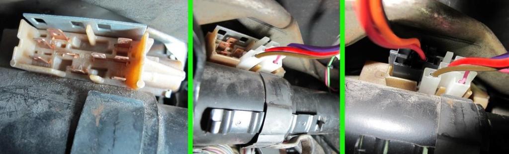
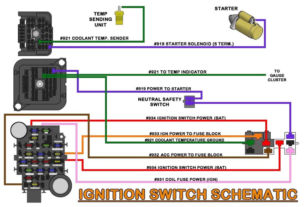
128 119
129 TURN SIGNAL SWITCH The turn signal switch provides power to each turn signal and turn signal indicator. Turn signal switch connectors are provided but not installed. As noted on page 10, if you use LED lights, two no-load flashers ARE required for the turn signals and hazard lights (Painless part #80230). The wires provided in the Painless harness for the turn signal connection can be identified by the wires reading TURN SWITCH. These wires can be seen in the Turn Signal Switch & Brake Switch Schematic on page 124, they are: BLACK: 18 gauge wire, printed [TURN SIGNAL SWITCH] #963 HORN SWITCH, this wire is a ground activation signal to the horn relay. The only time this wire is grounded is when the horn button on the steering wheel makes contact to a ground source. LT. BLUE: 16 gauge wire, printed [TURN SIGNAL SWITCH] #926 FRONT LEFT TURN SIGNAL, this wire provides power to the front left turn signal. This wire has power anytime the hazard switch is activated and also when the turn signal lever is in the down/left turn position and the ignition switch is in the ON/RUN position. BLUE: 16 gauge wire, printed [TURN SIGNAL SWITCH] #925 FRONT RIGHT TURN SIGNAL, this wire provides power to the front right turn signal. This wire has power anytime the hazard switch is activated and also when the turn signal lever is in the up/right turn position and the ignition switch is in the ON/RUN position. BROWN: 16 gauge wire, printed [TURN SIGNAL SWITCH] #951 EMERGENCY FLASHER POWER (BAT), this wire provides power to the hazard switch. It comes from the hazard flasher found on the fuse block. It is a battery power wire but it has power only when the hazard switch is activated which causes the flasher to send power through this wire. See Flashers on page 10 for how this process works. PURPLE: 16 gauge wire, printed [TURN SIGNAL SWITCH] #952 TURN SIGNAL POWER (IGN), this wire provides power to the turn signal switch. It comes from the turn signal flasher found on the fuse block. It is an ignition power wire but it has power only when the turn signal switch is activated, which causes the flasher to send power through this wire. See Flashers on page 10 for how this process works. YELLOW: 16 gauge wire, printed [TURN SIGNAL SWITCH] #949 TO LEFT REAR TURN SIGNAL, this wire provides power to the left rear turn signal. This wire has power anytime the hazard switch is activated or when the turn signal lever is in the down/left turn position and the ignition switch is in the ON/RUN position. This wire is also the brake light power wire and will have power anytime the brake pedal is pressed. GREEN: 16 gauge wire, printed [TURN SIGNAL SWITCH] #948 TO RIGHT REAR TURN SIGNAL, this wire provides power to the right rear turn signal. This wire has power anytime the hazard switch is activated or when the turn signal lever is in the up/right turn position and the ignition switch is in the ON/RUN position. This wire is also the brake light power wire and will have power anytime the brake pedal is pressed. WHITE: 16 gauge wire, printed [TURN SIGNAL SWITCH] #918 BRAKE LIGHT POWER [BRAKE LIGHT], this wire feeds the brake light power into the turn signal switch for vehicles with integrated turn/brake signals. This wire has power anytime the brake pedal is pressed. 120


130 Locate the black connectors in the kit that fit your column will use the smoother connector without the hinged lock columns will use the plug with the hinged terminal lock, seen in the photo below. Using the diagram below, pin each wire into its correct location on the connector. On columns, once all wires have been installed, fold the terminal lock down onto the connector. It will click/snap and lock the terminals in their place. Connect the now installed connector onto the connector on the steering column. 121
 or #80176 (4-pin, also included in our torque converter lockup kits #60109 & #60110), will be mounted on or near the pivot point of the brake pedal.")
![There are two wires found in the Painless chassis harness for proper brake switch connection, these wires will have a connector pre-installed, they are: ORANGE: 16 gauge wire, printed [BRAKE SWITCH]](/docs-images/92/109533477/images/131-1.jpg "#917 BRAKE SWITCH POWER (BAT), which provides power from the 20 amp STOP fuse. This wire has power at all times.")
131 BRAKE SWITCH The style of the brake switch depends on whether the truck is equipped with a 700r4 transmission or not. A switch, like Painless part #80172 (2-pin) or #80176 (4-pin, also included in our torque converter lockup kits #60109 & #60110), will be mounted on or near the pivot point of the brake pedal. There are two wires found in the Painless chassis harness for proper brake switch connection, these wires will have a connector pre-installed, they are: ORANGE: 16 gauge wire, printed [BRAKE SWITCH] #917 BRAKE SWITCH POWER (BAT), which provides power from the 20 amp STOP fuse. This wire has power at all times. WHITE: 16 gauge wire, printed [TURN SIGNAL SWITCH] #918 BRAKE LIGHT POWER [BRAKE SWITCH], this wire supplies power from the brake switch to the brake lights. The wire leads to the turn signal switch. Route the brake switch wires to the brake switch and connect them. Be sure to route the wires away from the moving parts of the brake pedal and/or clutch pedal. 122

132 4-PIN BRAKE SWITCHES Two pins will have contact with each other (or will be closed) when the brakes are not applied. This is usually the pair of terminals closest together. These pins are for torque converter lockup. When the brake is applied, these two pins will lose contact with each other, or open. These two pins are used for those with a 700r4 transmission or most other transmissions with a torque converter lockup clutch. Two pins will be separate (or open) when the brakes are not applied. This is the pair of terminals further apart, closest to the plunger of the switch. When the brake is applied, these two pins will have contact with each other, or close. You will need these two posts that are normally open for brake light function. 123
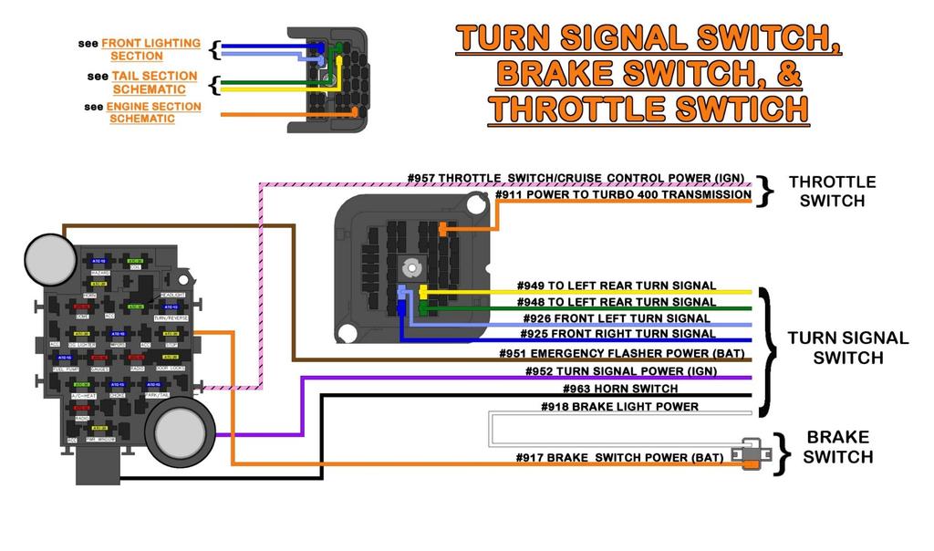
133 124
134 INSTRUMENT PANEL The instrument panel connections of the Painless harness vary according to the gauge cluster or aftermarket gauges you are using. Tach and clock wires have connectors preinstalled, but the printed circuit wires simply have terminals pre-installed, these wires are: GRAY: 18 gauge wire, printed [INSTRUMENT PANEL] #930 GAUGE LIGHT POWER, this wire provides a power source for gauge backlighting. This GRAY #930 is tied to the other 3 GRAY #930 wires coming from the headlight switch and going to the panel & radio backlight/dim. This wire has power anytime the headlight switch is in the Park/Tail Lights ON or Headlights ON position. This wire can also be seen in the Headlight Switch & Dimmer Switch Schematic on page 108. (2) PINK: 18 gauge wire, not printed due to their short length, these wire come from a splice with a wire printed [INSTRUMENT PANEL] #939 TO FUEL GAUGE [FUEL TANK SWITCH], this wire is a ground signal from the fuel level sending unit in the fuel tank. The resistance to ground will vary on this wire according to the amount of fuel in the tank. This wire can also be seen in the Tail Section Schematics starting on page 84. (3) PINK/BLACK: 18 gauge wires, not printed due to their short length, these wire come from a splice with a wire printed [INSTRUMENT PANEL] #935 GAUGE POWER (IGN), this wire provides a switched ignition power source to the cluster. This wire comes from the 10 amp GAUGES fuse on the fuse block. This wire has power anytime the key is in the ON/RUN position. GREEN: 18 gauge wire, printed [INSTRUMENT PANEL] #921 TO TEMP INDICATOR, this wire is a ground signal from the engine coolant temperature sending unit. The sending unit will create resistance to ground according to engine temperature. This resistance is transferred through this wire to the gauge. TAN: 18 gauge wire, printed [INSTRUMENT PANEL] #922 TO OIL PRESSURE INDICATOR, this wire is a ground signal from the oil pressure sending unit. The sending unit will create resistance to ground according to oil pressure. This resistance is transferred through this wire to the gauge. LIGHT GREEN: 18 gauge wire, printed [INSTRUMENT PANEL] #936 TO HIGH BEAM INDICATOR, this wire provides power to the high beam indicator when the headlight switch is in the ON position and the dimmer switch is in the HIGH position. LT. BLUE: 18 gauge wire, printed [INSTRUMENT PANEL] #937 LEFT TURN INDICATOR, this wire provides power to the left turn indicator when the turn signal switch is in the left turn position. BLUE: 18 gauge wire, printed [INSTRUMENT PANEL] #938 RIGHT TURN INDICATOR, this wire provides power to the right turn indicator when the turn signal switch is in the right turn position. (3) BLACK: 18 gauge wires, not printed due to their short length, these wires come from a splice with a wire printed [GROUND] #969 TO CHASSIS GROUND. These wires provide a ground source to the cluster. 125
135 TAN/WHITE: 18 gauge wire, printed #968 [INSTRUMENT PANEL] TO BRAKE WARNING INDICATOR, this wire is a ground activation wire for the brake light on the cluster from the brake pressure warning switch. This wire will be grounded, causing the light to illuminate when low brake fluid pressure condition occurs or when the ignition is in the ON/RUN position without the engine running. TAN/WHITE: 18 gauge wire, printed #968 [EMERGENCY BRAKE] TO EMERGENCY BRAKE, this wire is a ground activation wire for the brake light on the cluster from the emergency brake. If the emergency brake is still applied, this wire will be grounded causing the light to illuminate. YELLOW: 18 gauge wire, printed [SEAT BELT RELAY] #990 SEAT BELT IND. LIGHT POWER [INSTRUMENT PANEL], this wire provides a power activation source to the seat belt indicator light in the cluster. WHITE: 14 gauge wire, printed [INSTRUMENT PANEL] #914 ALTERNATOR REGULATOR POWER (IGN), this wire provides an ignition power source for the voltage regulator from the 10 amp RADIO fuse. This wire will have power when the ignition is in the ACC & ON/RUN positions. This wire is connected to the other #914 wire. WHITE: 14 gauge wire, printed [INSTRUMENT PANEL] #914 TO ALTERNATOR REGULATOR, this wire provides an ignition power source to the voltage regulator in the engine compartment. This wire is connected to the other #914 wire. When using the original style factory alternators, the two #914 WHITE wires MUST remain connected together; unless, you are using a charge indicator light. On these GM trucks, the base model dash clusters have an indicator light built into them. If the two #914 wires are disconnected and/or are not connected to an indicator light, the alternator will not charge. If you are using a one wire alternator, you can disconnect these wires to avoid having an unused power wire in the engine compartment as the wire printed #914 TO ALTERNATOR REGULATOR provides power out to the alternator. FACTORY PRINTED CIRCUIT GAUGES This kit provides a factory, 18-pin connector for factory gauge clusters. The wires in the harness have been pre-terminated with the proper terminals for this connector. Due to the multiple different clusters installed in these vehicles, the connector could not be pre-installed. Use the diagrams on the following pages to match the pinout with your cluster and install the connector. As noted in some diagrams, you may have leftover wires. If you have a PINK/BLACK #935 wire left over, insulate the end of this wire or it will short to the cluster of to the dash. The brown/white wire shown for the Check Engine Light on 1987 cluster is not supplied. Do not get it confused with the BROWN/WHITE #955 wire. It is shown for those running standalone/aftermarket EFI systems who may want to connect the check engine light ground signal from their ECM to the factory cluster. 126

136 To identify the terminal location there are numbers molded on the side of the connector. You can also reference the end tabs as one is smooth and larger while the other tab has a ridge and is smaller. You can also use the key, located on the side of the connector between pins 16/17 on the diagrams. DO NOT MIS-PIN THE CONNECTOR OR YOU WILL BURN OUT THE PRINTED CIRCUIT. 127


137 This following step is not necessary if you are using a one wire alternator: If you have an indicator light cluster, locate the two WHITE wire pigtails from the bag kit. These pigtails will plug into the two WHITE #914 wires in the instrument panel section that come connected together. Disconnect the two #914 on the Painless harness and connect these pigtails. Plug the pigtails into pins 6 and 7 of the printed circuit connector. It doesn t matter which wire goes into pin 6 or 7. It is also recommended, but not necessary, to wire in a 15-ohm 2-watt resistor between the power in and power out, seen in the diagram below. This will still provide enough power to the voltage regulator to allow the alternator to still charge in the event the bulb burns out. This resistor can be found through online electronic component suppliers such as Mouser or Allied Electronics under part # OY150KE. 128
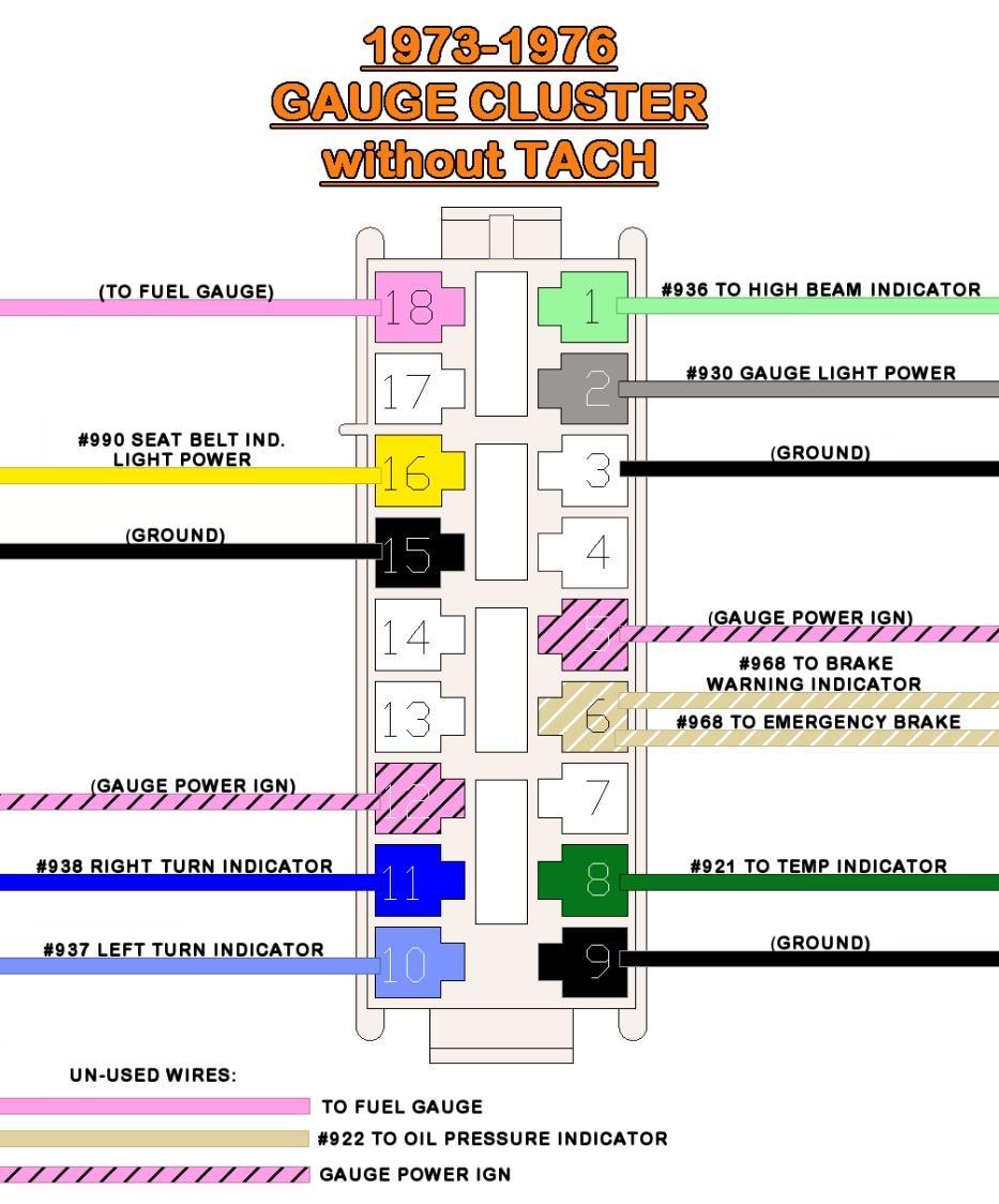
138 129
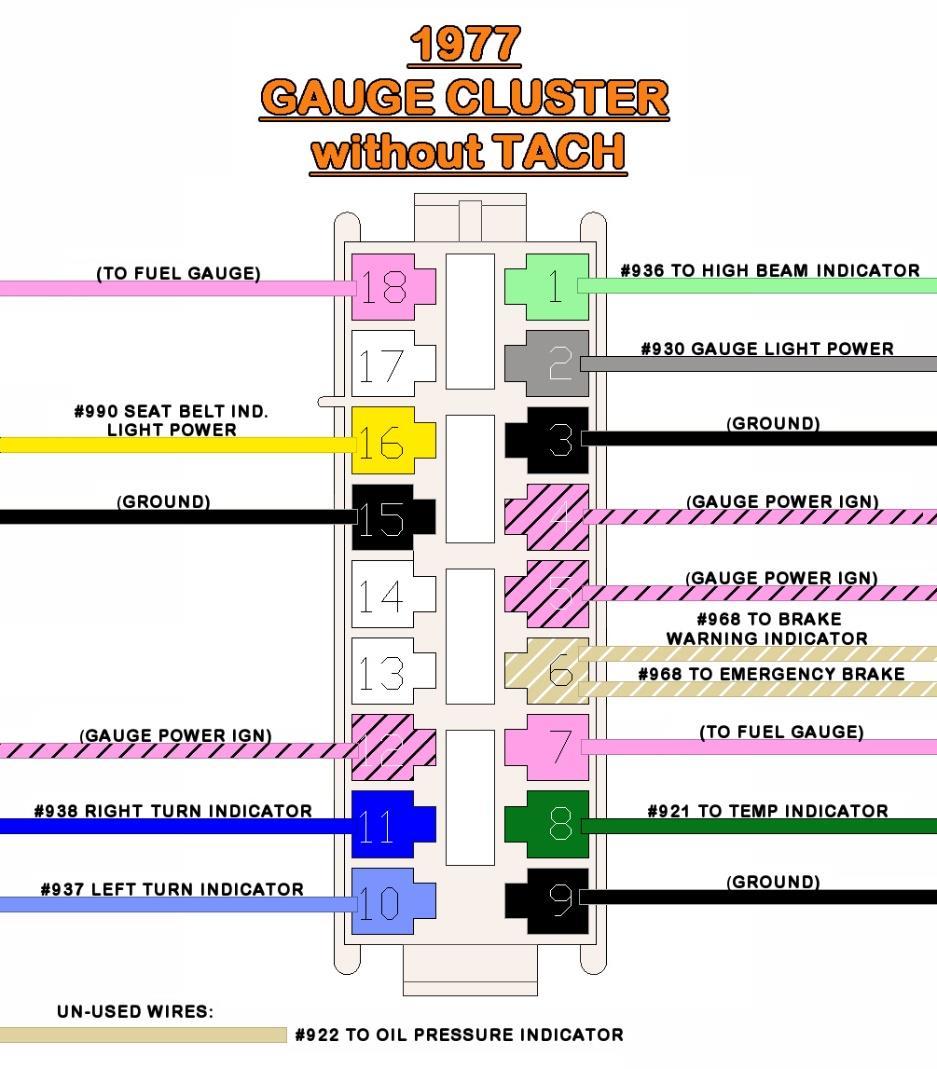
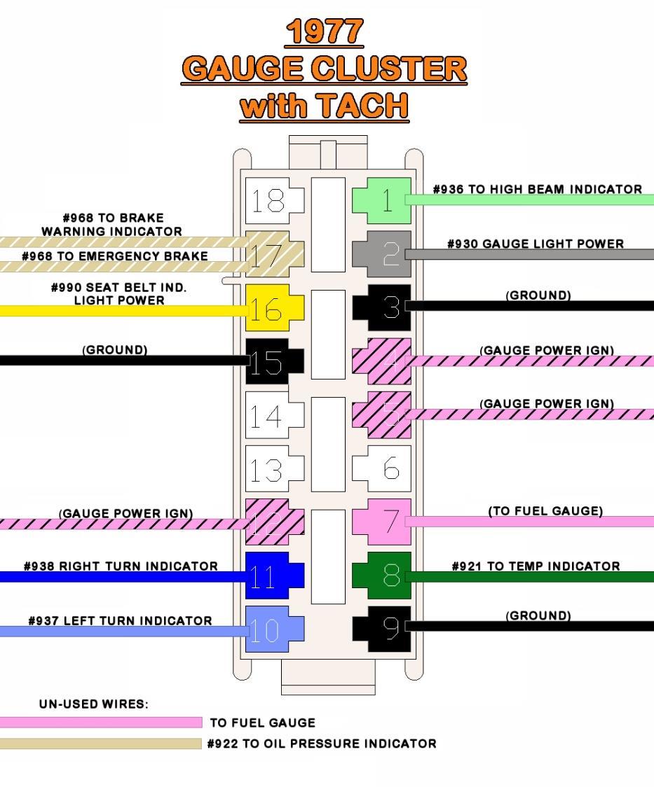
139 130

140 4X4 INDICATOR The factory 4x4 indicator socket and ground wire will need to be re-used. This ground wire is a white wire that connects to the 2-pin switch on the transfer case. The other pin on the transfer case switch will connect to a chassis ground source. This Painless harness supplies the power wire to the light. This wire is: BROWN/WHITE: 18 gauge wire, printed [INSTRUMENT PANEL] #955 4-WHEEL DRIVE INDICATOR B+. This wire provides a switched ignition power source to the 4x4 indicator. This wire comes from the 10 amp GAUGES fuse on the fuse block. This wire has power anytime the key is in the ON/RUN position. Splice this BROWN/WHITE #955 wire to the brown wire coming from your socket. Splices and heat shrink have been provided. If you do not have a four wheel drive, insulate the end of this wire, it is a power wire and WILL short to the dash if left uninsulated. This wire could also be used to power aftermarket gauges 131
.")
141 TACHOMETER This harness comes pre-wired for those with a factory tachometer cluster. Three wires with a 3-pin connector can be found with the instrument panel wires. These three wires are: PINK: 18 gauge wire, not printed due to its short length, this wire comes from a splice with a wire printed [INSTRUMENT PANEL SECTION] #935 GAUGE POWER (IGN). This wire provides a switched ignition power source to the tachometer. This wire comes from the 10 amp GAUGES fuse on the fuse block. This wire has power anytime the key is in the ON/RUN position. BLACK: 18 gauge wire, printed [INSTRUMENT PANEL] #969 TACH GROUND, this wire comes from the clock connector where it doubles with the ground wire. This wire is part of the [GROUND] #969 TO CHASSIS GROUND CIRCUIT. This wire will provide a ground source to the tachometer. BROWN: 18 gauge wire, printed [INSTRUMENT PANEL] #923 TACHOMETER SIGNAL, this wire provides a signal to the tachometer from the negative side of the coil or from your ignition box. Plug the connector on the Painless harness into the cluster. Aftermarket Tachometer If you are using an aftermarket tach, the pre-installed connector cannot be used. Remove the connector from the three wires of the Painless harness. Connect these three wires to the wires or tabs of your aftermarket tachometer. Consult the tachometer instructions for proper hookup. Additionally, most aftermarket tachometers will also require a gauge lighting source, this can be obtained by splicing into any of the gray wires found on the dash harness. 132

142 CLOCK This harness comes pre-wired for those with a factory clock cluster. Three wires with a 2-pin connector can be found with the instrument panel wires. These three wires are: ORANGE: 18 gauge wire, printed #965 CLOCK POWER, this wire will provide constant battery power. This wire comes from the 20 amp CIG LIGHTER fuse on the fuse block and can be seen in the Accessory Schematic above. (2) BLACK: 18 gauge wire, one printed [CLOCK] #969 GROUND, this wire comes from a splice with other wires of the [GROUND] #969 TO CHASSIS GROUND circuit. These wires provide a ground source to the clock. The other wire, not printed due to its short length, provides a ground source to the tachometer connector. Plug the connector on the Painless harness into the cluster. 133
. This is a universal gauge cluster harness that has all the splicing and termination pre-installed for these types of applications.")

143 SEPARATE HARNESSES PAINLESS #30301 & To facilitate wiring individual aftermarket gauges Painless offers, and recommends, the use of Painless part #30301 (#30302 if using an electric speedometer). This is a universal gauge cluster harness that has all the splicing and termination pre-installed for these types of applications. This harness also offers you the benefit of having an inline connector instead of hardwiring the chassis harness directly to the gauges. Using the terminals and connector found in the #30301 or #30302 kits, install the wires of the Painless chassis harness according to the diagram below. Use the numbers on the connectors as well as the circled reference points in the diagram for the proper cavity location. A gauge light ground will not be used. 134
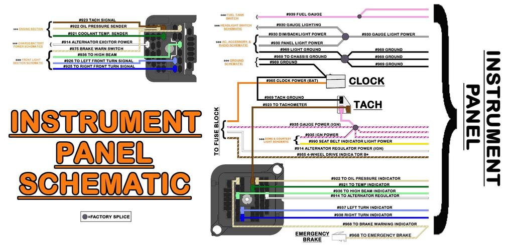
144 135


145 HARDWIRING For those who choose to wire aftermarket gauges with just the wires found in the Painless chassis harness, and not purchase an additional gauge harness, the following steps will walk you through the process of distributing power and ground as well as connecting the sender wires. The following diagrams only show temp, oil pressure, volt, and fuel level gauges. Power, ground, and sender wires connect in the same manner to speedometers and tachometers. Power to the gauges comes from the PINK/BLACK #935 wires, and it needs to be connected to the I or 12v post on each gauge. The power wire can be connected in one of two ways: #1) Splicing- This is when you connect multiple wires to a single wire to distribute power/ground to multiple components. In this case, a splice from one of the PINK/BLACK #935 wires is powering wires to several gauges. #2) Chaining or Jumpering- Run a PINK/BLACK #935 wire to a power post. Before terminating the wire with the proper terminal, insert another wire into the terminal and crimp. You now have 2 wires in 1 terminal. This additional wire then routes to the next gauge s power post. Before terminating that wire with the proper terminal, insert another wire into the terminal; and so on. 136


146 Grounds need to be supplied to the gauge lights and to any ground tab on the gauges. To make these ground connections you can splice from the provided ground wires to all the gauges or chain/jumper it all together. Both methods can be seen in the following two drawings: 137


147 Gauge light power is supported by the GRAY #930 wire. This wire connects to one of the leads for the gauge light or to the gauge light tab found on gauges with LED backlighting. To make these connections you can splice from this GRAY #930 wire to all the gauges or chain/jumper it all together. 138

148 The last connections that need to be made are the sending unit wires or signal wires. These are the wires which come from the temperature sending unit, oil pressure sending unit, and fuel level sending unit. Not shown in the diagram, but also provided in the Painless chassis harness is the BROWN #923 TACHOMETER SIGNAL wire. 139

149 DOME LIGHT SECTION The Dome Light Section has 4 wires: dome light power, dome light ground, amplifier power, and seat belt ground signal. SEAT BELT The seat belt switch can be found at the base of the driver side seat belt retractor. A single wire is all that is needed for this connection, it is: BLACK/WHITE: 18 gauge wire, printed [SEAT BELT RELAY] #980 SIGNAL FROM SEAT BELT [SEAT BELT], this wire sends a ground signal to the seat belt relay, turning off the light in the dash. This ground circuit is complete when the seat belt is fastened. Using a single-pin connector and a factory style terminal, connect this BLACK/WHITE #980 wire to the seat belt switch. The connector provided is not keyed like the factory connector, this does not affect the connection. 140

150 DOME LIGHT The dome light has constant battery power applied to it. This light, along with the under dash courtesy lights, are ground activated by the door jamb switches and also by turning the headlight switch to the DOME LIGHT ON position. These wires can be seen in the Tail Section Schematics starting on page 84, they are: ORANGE: 18 gauge wire, printed [DOME SECTION] #971 DOME LIGHT POWER this power wire comes from the 10 amp DOME fuse on the fuse block. This fuse has battery power and is hot at all times. This wire can also be seen in the Dome / Courtesy Light Schematic on page 106. WHITE: 18 gauge wire, printed [DOME SECTION] #961 TO DOME LIGHT GROUND, this wire is the ground wire that activates the dome light. When this wire is grounded it completes the voltage path causing the light to illuminate. This ground will come from either door jamb switch or the headlight switch. This wire can also be seen in the Dome / Courtesy Light Schematic on page 106. In most cases, these wires will attach to the factory dome light wires. The factory wires coming from the dome light can usually be found in the rear of the cab, on the driver s side. A connector and terminals, seen to the right, have been provided to connect the Painless harness to the factory pigtail coming from the dome light. This factory dome light wires also contain a jumper to power the cargo switch for those with that option. If you do not have a factory pigtail, there has been ample length supplied to allow routing the ORANGE #971 and the WHITE #961 to the dome light fixture. In most cases, this will require the headliner of the vehicle to be removed. If you have a cargo lamps switch, this ORANGE #971 will also provide power to the switch. AFTERMARKET AMPLIFIER For those with an audio sound system, a wire has been provided in the Painless harness to allow for amplifier activation. This wire is only needed if you have an amplifier: BLUE: 18 gauge, printed [DOME SECTION] #998 AMP TURN ON [RADIO SECTION], this is a switched power source that comes from the radio/head unit and not a power source that comes directly from the fuse block. Route and connect the #998 wire to the Remote Turn On terminal of the amplifier. If you have multiple amplifiers, double up the cut off portion of #998 with the #998 at the first amp and route it to the Remote Turn On terminal of the second amplifier. 141

151 TESTING THE SYSTEM Use a small (10 amp or less) battery charger to power up the vehicle for the first time to test the circuits. If there is a problem anywhere, the battery charger's low amperage and internal circuit breaker will provide circuit protection. Make sure the negative (-) battery cable is connected to the frame or engine block, and make sure there is a ground between the engine and frame. The negative battery cable should still be disconnected from the Battery Connect the positive (+) battery cable to the positive side of the battery and make sure the other end of this cable is connected to the B+ side of the starter solenoid. At this point connect the RED #915 from the MIDI fuse to the positive side of the battery, either through the starter lug or the battery lug. Connect the Battery Charger's NEGATIVE cable to the automobile chassis, engine block, or to the disconnected negative battery cable. Do NOT connect the Battery Charger's NEGATIVE cable to the Battery. Connect the Battery Charger's POSITIVE cable to the automobile's positive battery terminal lug. INDIVIDUALLY turn on each light, ignition, wiper circuit, etc. and check for proper operation. Turn off each component before testing another. Note: If you try to test more than one circuit at a time, the charger will not provide enough amperage for each circuit to work correctly. After all circuits have been checked, disconnect the battery charger and attach the vehicle's negative (ground) battery cable to the battery. Once testing is complete, re-install any panels, lens, or other parts that were removed during the harness installation. You are now finished installing this Painless Harness, congratulations! 142
152 WIRE INDEX The index is listed in the same order in which the manual instructed components to be connected. The BLUE descriptions indicate sections found throughout the harness. ORIGIN indicates where the opposite end of this wire is. ENGINE HARNESS WIPER ( ) SECTION Color Gauge Wire Print Origin Black 16 not printed; Low Speed Wiper Switch Light Blue 16 not printed; High Speed Wiper Switch Blue 16 not printed; washer pump ground Wiper Switch Yellow 16 not printed; washer pump power Wiper Switch Yellow 16 not printed; Wiper Motor Power Wiper Switch WIPER ( ) SECTION Color Gauge Wire Print Origin Pink 18 #983 WASHER ACTIVATION Wiper Switch Purple 18 not printed; High Speed Wiper Switch Gray/White 18 not printed; Low Speed Wiper Switch Gray/White 18 not printed; Low Speed Wiper Switch Black/Blue 18 not printed; Park Switch Wiper Switch White 18 not printed; Wiper Motor Power Wiper Switch White 18 #981 WASHER POWER (IGN) Wiper Switch 143
153 HEADLIGHT SECTION Color Gauge Wire Print Origin Tan/White 18 #975 BRAKE WARN SWITCH Intrument Panel Light Blue 16 #926 LEFT FRONT TURN SIGNAL Turn Switch Blue 16 #925 RIGHT FRONT TURN SIGNAL Turn Switch Gray/White 16 #901 RELAY ACTIVATION/ACC POWER (IGN) Fuse Block Tan 14 #909 TO LOW BEAM Dimmer Switch Tan 14 #909 TO LOW BEAM Dimmer Switch Light Green 14 #908 TO HIGH BEAM Dimmer Switch Light Green 14 #908 TO HIGH BEAM Dimmer Switch Brown 18 #927 TO PARK LIGHT Headlight Switch Brown 18 #927 TO PARK LIGHT Headlight Switch Brown 18 #927 TO MARKER LIGHT Headlight Switch Brown 18 #927 TO MARKER LIGHT Headlight Switch Green 14 #924 TO HORN POWER Horn Relay Green 14 #924 TO HORN POWER Horn Relay ENGINE SECTION Color Gauge Wire Print Origin Pink 14 #920 COIL POWER Fuse Block Green 18 #921 COOLANT TEMP SIGNAL Instrument Panel Tan 18 #922 OIL PRESSURE SENDER Instrument Panel Brown 18 #923 TACH SIGNAL Instrument Panel Red 16 #954 ELECTRIC CHOKE POWER Fuse Block Orange 16 #911 TURBO 400 KICK DOWN Throttle Switch Purple 12 #919 STARTER SOLENOID (S. TERM) NSS ALTERNATOR SECTION Color Gauge Wire Print Origin White 14 #914 ALTERNATOR EXCITOR POWER Fuse Block Red 16 #995 REGULATOR POWER (BATTERY) Fuse Block MIDI SECTION Color Gauge Wire Print Origin Red 8 #916 BATTERY POWER SOURCE (MIDI FUSE) Fuse Block 144
154 TAIL SECTION Color Gauge Wire Print Origin Yellow 16 #949 TO LEFT REAR TURN SIGNAL Turn Switch Green 16 #948 TO RIGHT REAR TURN SIGNAL Turn Switch Brown 16 #929 TO TAIL LIGHT Headlight Switch Light Green 16 #956 REVERSE LIGHTS Reverse Switch Light Green 16 #997 VALVE ACTIVATION (DUAL TANKS ONLY) Fuel Tank Switch Green 16 #999 TANK SIGNAL (DUAL TANKS ONLY) Fuel Tank Switch Pink 18 #939 TO FUEL SENDING UNIT Fuel Tank Switch INTERIOR HARNESS SEAT BELT RELAY SECTION Color Gauge Wire Print Origin Yellow 18 #990 SEAT BELT IND. LIGHT POWER Instrument Panel Black/White 18 #980 SIGNAL FROM SEAT BELT Dome Light Section Black 18 not printed; Ground Chassis Ground Pink/Black 18 #935 IGN POWER Fuse Block DIMMER SWITCH SECTION Color Gauge Wire Print Origin Light Green 14 #908 HIGH BEAM POWER Headlight Section Tan 14 #909 LOW BEAM POWER Headlight Section Yellow 14 #907 DIMMER SWITCH POWER Headlight Switch EMERGENCY BRAKE Color Gauge Wire Print Origin Tan/White 18 #968 TO EMERGENCY BRAKE Headlight Section GROUND Color Gauge Wire Print Origin Black 16 #969 TO CHASSIS GROUND Ground Splice Black 16 #969 TO CHASSIS GROUND Ground Splice DRIVER DOOR JAMB SWITCH Color Gauge Wire Print Origin White 18 #961 DOME/COURTESY LIGHT ACTIVATION Courtesy Light Section 145
155 A/C HEAT Color Gauge Wire Print Origin Brown 14 #904 HEAT-A/C POWER Fuse Block Black 18 #969 TO CHASSIS GROUND Ground Section Gray 18 #930 PANEL LIGHT POWER Headlight Switch ACCESSORIES SECTION Color Gauge Wire Print Origin Orange/Black 14 #912 DOOR LOCK POWER (BAT) Fuse Block Grey/White 16 #901 ACC. OUTPUT TO ENG. HARNESS Headlight Section Pink 14 #913 POWER WINDOW POWER (IGN) Fuse Block Grey/White 16 #906 ACCESSORY POWER (IGN) Fuse Block Tan 14 #903 CIGARETTE LIGHTER POWER (BAT) Fuse Block RADIO SECTION Color Gauge Wire Print Origin Yellow 18 #940 RADIO POWER (BAT) Fuse Block Red 18 #941 RADIO POWER (IGN) Fuse Block Blue 18 #998 AMP TURN ON Dome Light Section Black 18 #969 GROUND Ground Splice Gray 18 #930 DIM/BACKLIGHT POWER Headlight Switch FUEL TANK SWITCH Color Gauge Wire Print Origin Pink/Black 14 #947 IGN POWER TO FUEL TANK SWITCH Fuse Block Green 16 #999 SIGNAL (DUAL TANKS ONLY) Fuel Sender Light Green 16 #997 SIGNAL (DUAL TANKS ONLY) Fuel Tank Selector Pink 18 #939 TO FUEL GAUGE Instrument Panel Tan/White 18 #939 FROM FUEL SENDING UNIT Fuel Sender COURTESY LIGHT SECTION Color Gauge Wire Print Origin Orange 18 #971 DRIVER COURTESY LIGHT POWER Fuse Block White 18 #961 DRIVER COURTESY LIGHT GROUND Headlight Switch Orange 18 #971 PASS. COURTESY LIGHT POWER Fuse Block White 18 #961 PASS. COURTESY LIGHT GROUND Headlight Switch COURTESY LIGHT SECTION Color Gauge Wire Print Origin White 18 #961 DOME/COURTESY LIGHT ACTIVATION Headlight Switch 146
156 HEADLIGHT SWITCH SECTION Color Gauge Wire Print Origin Red 12 #928 HEADLIGHT SWITCH POWER (BAT) Fuse Block Orange 14 #959 HEADLIGHT SWITCH POWER (BAT) Fuse Block Yellow 14 #907 DIMMER SWITCH POWER Dimmer Switch Brown 16 #927 FRONT PARK LIGHTS Headlight Section Gray 18 #930 GAUGE LIGHTING Instrument Panel Brown 16 #929 TAIL LIGHTS Tail Section White 18 #961 DOME/COURTESY LIGHT ACTIVATION Courtesy Light Section Gray 18 not printed; PANEL LIGHT POWER Wiper Switch WIPER SWITCH SECTION Color Gauge Wire Print Origin Black 16 #969 GROUND Chassis Ground Gray 18 not printed; PANEL LIGHT POWER Headlight Switch Pink 18 #983 WASHER ACTIVATION Washer Pump Purple 18 #977 HIGH SPEED Wiper Motor Gray/ White 18 #978 LOW SPEED Wiper Motor Black/ Blue 18 #980 PARK Wiper Motor REVERSE SWITCH SECTION Color Gauge Wire Print Origin Light Green 16 #958 REVERSE SWITCH POWER (IGN) Fuse Block Light Green 16 #956 POWER TO REVERSE LIGHTS Tail Section NEUTRAL SAFETY SWITCH SECTION Color Gauge Wire Print Origin Purple 12 not printed; TO IGN SWITCH Ignition Switch Purple 12 #919 POWER TO STARTER Starter Sol. THROTTLE SWITCH SECTION Color Gauge Wire Print Origin Pink/Black 18 #957 THROTTLE SWITCH/CRUISE CONTROL POWER (IGN) Fuse Block Orange 18 #911 POWER TO TURBO 400 TRANSMISSION Transmission 147
157 IGNITION SWITCH SECTION Color Gauge Wire Print Origin Red 12 #934 IGNITION SWITCH POWER (BAT) Fuse Block Red 12 #934 IGNITION SWITCH POWER (BAT) Fuse Block Orange 12 #933 IGN POWER TO FUSE BLOCK Fuse Block Brown 12 #932 ACC POWER TO FUSEBLOCK Fuse Block Pink 14 #931 COIL FUSE POWER (IGN) Fuse Block Purple 12 not printed; TO NSS NSS Green 18 #921 COOLANT TEMPERATURE GROUND Temp Sender TURN SIGNAL SWITCH SECTION Color Gauge Wire Print Origin White 16 #918 BRAKE LIGHT POWER Brake Switch Blue 16 #925 FRONT RIGHT TURN SIGNAL Headlight Section Light Blue 16 #926 FRONT LEFT TURN SIGNAL Headlight Section Purple 16 #952 TURN SIGNAL POWER (IGN) Fuse Block Black 18 #963 HORN SWITCH Fuse Block Green 16 #948 TO RIGHT REAR TURN SIGNAL Tail Section Yellow 16 #949 TO LEFT REAR TURN SIGNAL Tail Section Brown 16 #951 EMERGENCY FLASHER POWER (BAT) Fuse Block BRAKE SWITCH SECTION Color Gauge Wire Print Origin Orange 16 #917 BRAKE SWITCH POWER (BAT) Fuse Block White 16 #918 BRAKE LIGHT POWER Turn Signal Switch 148
158 INSTRUMENT PANEL SECTION Color Gauge Wire Print Origin Yellow 18 #990 SEAT BELT IND. LIGHT POWER Seat Belt Relay White 14 #914 ALTERNATOR REGULATOR POWER (IGN) Fuse Block White 14 #914 TO ALTERNATOR REGULATOR Alt. Regulator Brown/White 18 #955 4-WHEEL DRIVE INDICATOR B+ Fuse Block Light Blue 18 #937 LEFT TURN INDICATOR Turn Switch Blue 18 #938 RIGHT TURN INDICATOR Turn Switch Pink 18 not printed; TO FUEL GAUGE Fuel Tank Switch Pink 18 not printed; TO FUEL GAUGE Fuel Tank Switch Pink/Black 18 not printed; Ign Power Fuse Block Pink/Black 18 not printed; Ign Power Fuse Block Pink/Black 18 not printed; Ign Power Fuse Block Tan/White 18 #968 TO EMERGENCY BRAKE Emergency Brake Tan/White 18 #968 TO BRAKE WARNING INDICATOR Headlight Section Tan 18 #922 TO OIL PRESSURE INDICATOR Engine Section Light Green 18 #936 HIGH BEAM INDICATOR Dimmer Switch Green 18 #921 TO TEMP INDICATOR Engine Section Grey 18 #930 INSTRUMENT PANEL LIGHTING Headlight Switch Black 16 not printed; Ground Chassis Ground Black 16 not printed; Ground Chassis Ground Black 16 not printed; Ground Chassis Ground TACH SECTION Color Gauge Wire Print Origin Brown 18 #923 TACHOMETER SIGNAL Engine Section Pink 18 not printed; Power Fuse Block Black 18 #969 TACH GROUND Clock CLOCK SECTION Color Gauge Wire Print Origin Orange 18 #965 CLOCK POWER (BAT) Fuse Block Black 18 #969 GROUND Chassis Ground Black 18 #969 TACH GROUND Tachometer DOME SECTION Color Gauge Wire Print Origin Black/White 18 #980 SIGNAL FROM SEAT BEALT Seat Belt Relay White 18 #961 TO DOME LIGHT GROUND Headlight Switch Orange 18 #971 DOME LIGHT POWER Fuse Block Blue 18 #998 AMP TURN ON Radio 149
159 Painless Performance Limited Warranty and Return Policy Chassis harnesses, fuel injection harnesses, and Trail Rocker units are covered under a lifetime warranty. All other products manufactured and/or sold by Painless Performance are warranted to the original purchaser to be free from defects in material and workmanship under normal use. Painless Performance will repair or replace defective products without charge during the first 12 months from the purchase date. No products will be considered for warranty without a copy of the purchase receipt showing the sellers name, address, and date of purchase. You must return the product to the dealer you purchased it from to initiate warranty procedures. 150
160 151

161 BULKHEAD TEMPLATE For Vehicles with No Bulkhead Hole The dimension photo on this page shows how you can cut the bulkhead hole clean and precise using a 1 ¼ hole saw to cut 4 holes, using a jigsaw or cut off wheel to connect the outsides of the 1 ¼ holes, and using a ¼ drill bit for the fuse block mounting holes. Mark the centers of all 6 holes (the 1 ¼ holes as well as the ¼ ) holes before any cutting is done. 152
Trail Rocker Installation Instructions
 Trail Rocker Installation Instructions Manual #90580 For Installing Painless Part Numbers: 57000 and 57001 Painless Performance Products recommends you, the installer, read this installation manual from
Trail Rocker Installation Instructions
 Trail Rocker Installation Instructions Manual #90581 For Installing Painless Part Numbers: 57002 Painless Performance Products recommends you, the installer, read this installation manual from front to
Track Rocker Installation Instructions
 Track Rocker Installation Instructions For Installing Painless Part Numbers: 58103: 8-Switch Customizable Track Rocker Switch Panel w/ Flanged Mount 58106: 6-Switch Customizable Track Rocker Switch Panel
Trail Rocker Installation
 Trail Rocker Installation Instructions Customizable Trail Rocker Control System For Installing Painless Part Number: 57100 Manual #90616 Painless Performance Products recommends you, the installer, read
Track Rocker Installation Instructions
 Track Rocker Installation Instructions Customizable Track Rocker Control System For Installing Painless Part Number: 58100 Track Rocker Relay Center Manual #90641 Painless Performance Products recommends
Trail Rocker Installation
 Trail Rocker Installation Instructions 4, 6, or 8 - Switch Customizable Trail Rocker Switch Panel w/ Flanged Mount For Installing Painless Part Number: 57103, 57106, & 57109 Manual #90636 Painless Performance
Wire Harness Installation Instructions Manual #90576 For Installing:
 Wire Harness Installation Instructions Manual #90576 For Installing: #20112 Direct Fit Camaro Harness 1970-73 #20113 Direct Fit Camaro Harness 1974-77 #20114 Direct Fit Camaro Harness 1978-81 All 26 Circuit
Wire Harness Installation Instructions
 Wire Harness Installation Instructions For Installing: Part #50001 Race Car Kit/8 Circuit Part #50201 8 Switch Dash Mounted Panel Part #50202 8 Switch Roll Bar Mounted Panel Manual #90502 Painless Performance
Wire Harness Installation Instructions Manual #90571 PART 1 For Installing: #10309 Basic Customizable Nostalgia All Black Chassis Harness 17 Circuit
 Wire Harness Installation Instructions Manual #90571 PART 1 For Installing: #10309 Basic Customizable Nostalgia All Black Chassis Harness 17 Circuit Painless Performance Products recommends you, the installer,
jegs.com
 Contents Wiring Harness w/ Fuse Panel Installation Instructions Turn Signal Plug w/ Terminals 2 Headlight Plugs 3/4 Grommet 10 ¼ Terminals 4 Ring Terminals 10 Wire Ties Fusible Link 2 Screws & Nuts 2 Plastic
Wire Harness Installation Instructions Manual #90563
 Wire Harness Installation Instructions Manual #90563 For Installing: #10113 Direct Fit 1966-1977 Bronco Harness 28 Circuit w/switches Perfect Performance Products, LLC Painless Performance Products Division
INSTRUCTIONS. 20 Circuit Wiring Kit Instructions October 2009, Speedway Motors, Inc.
 1 MAIN FUSE PANEL The main fuse panel harness s designed to be mounted under the dash a the firewall in an area close to the steering column. The enclosed representation of the main dash harness shows
Off-Road Switch Panel Installation Instructions
 Off-Road Switch Panel Installation Instructions 50330: Off-road 4 Toggle switches/dash Mount w/keyed Ignition Switch 50332: Off-road 6 Toggle switches/dash Mount w/keyed Ignition Switch Painless Performance
Trail Rocker Installation Instructions
 Trail Rocker Installation Instructions Trail Rocker - Genesis Bracket For Installing Painless Part Number: 57200 Manual # 90591 To be used with Painless Kit # s: 57000-57005 Painless Performance Products
CLASSIC UPDATE WIRING KIT
 by Randy Irwin 1955-57 CLASSIC UPDATE WIRING KIT Randy Irwin - Technical Writer Randy has been involved in the Chevy parts business for over 25 years. He is a wizard at creating, making and modifying custom
WIRE HARNESS INSTALLATION INSTRUCTIONS
 WIRE HARNESS INSTALLATION INSTRUCTIONS For Installing: #10206 Classic Plus Customizable GM Pickup Chassis Harness 1967-72 28 Circuit Manual #90510 PERFECT PERFORMANCE PRODUCTS, LLC Painless Performance
Rear Body 40D 156A 24 17A 151 3D. 8A,8B,8C under hood light. Horn Relay 91
 fuse box as viewed from the wire entry side Mating connector is plugged into Power Accessory connector 40D Rear Body 19 18 9B 30 LH Courtesy Light 40A,D 4D, 43 156B,C 16 16A 4C 3D 3C 16A 3G 4B 3G 116 4A&130
Installation Instructions. Manual # For Installing: Part # Painless Gauge Controller
 Installation Instructions Manual #90579 For Installing: Part #60650- Painless Gauge Controller Perfect Performance Products, LLC Painless Performance Products Division 2501 Ludelle Street Fort Worth, TX
accessory connection rear body connection 40G 17A instrument cluster and map lamp ground 150A,B 15A 14A Circuit Branch 500A fog lamp switch
 accessory rear body 19 9 11 instrument cluster and map 10A, 0 4 3 7 40G 18 30 17A 24 1A 14A 9 8A instrument cluster 4E 31 3 121 11 33 401 10A 39A 400 30 washer and wiper switch 93A, 94 93 glovebox, map
Ford Mustang V6 OEM-Style Fog Light Kit Parts List: Quantity: Tool List:
 2015-2017 Ford Mustang V6 OEM-Style Fog Light Kit Parts List: Quantity: Tool List: LED Foglights/ Bezels 2 Flat head & Phillips screwdriver (if you ordered part#3600) Ratchet & Socket set OR Wiring harness
40A A 40B. Horn Relay Connector. Brake Switch. Third Brake Light. Brake Switch. Brake Switch. Wires. page 3. Rear Body Feed Wires.
 Fuse Box Connections (viewed from underside) 4D 4C 4D 0 50 300 4C 43 7 39 3 6 4 93 A 2G 2F 2E 2D 2C 2B 2G 2F 2E 40 69A 2 1 5 27 69A 3A B 40A,B 11A,B 40A 156 Dimmer Dome Feed page 2 Horn Relay 2D 2 29 40B
PIN BULKHEAD CONNECTOR KIT
 2501 Ludelle Street Fort Worth, Texas 76105 817-244-6212 Phone 817-244-4024 Fax 888-350-6588 Sales 800-423-9696 Tech E-mail: painless@painlessperformance.com Web: www.painlessperformance.com 40130 22 PIN
Mustang Classic Update Series Kit
 accessory rear body 19 9 11 instrument cluster and map 10A, 0 4 3 7 40G 18 30 17A 24 1A 14A 9C 8A instrument cluster 4E 31 3 121 11 401 10A 3 400 30 washer and wiper switch 93A, 93 glovebox, map light,
INSTRUCTIONS Circuit Wiring Kit Instructions _2017. Fuse Box Connections. (viewed from underside) 2018, Speedway Motors, Inc.
 2018, Speedway Motors, Inc.") Fuse Box Connections (viewed from underside) 4D 4C 100 50 300 4D 4C 4B 4A 43 107 39 103 3B 2G 104 93 2F 2E 2D 2C 2B 40 69A 102 101 105 2G 2F 2E 3A A 2A B 40A,B 27 69A 106 201, Speedway Motors, Inc. 1 Fuse
Fuse Box Connections (viewed from underside) 4D 4C 100 50 300 4D 4C 4B 4A 43 107 39 103 3B 2G 104 93 2F 2E 2D 2C 2B 40 69A 102 101 105 2G 2F 2E 3A A 2A B 40A,B 27 69A 106 201, Speedway Motors, Inc. 1 Fuse
Instrument Cluster 30 33B 39B A B C D E F E F G H J. Connector. Circuit Branch #4. Circuit Branch #5. Circuit. Branch #6 150A. Ground.
 16 4D, 43 4B 4A & 130 100 50 39A,B,C 300 4C 4B 4C 107 3C 3D 3C 3G 3B 3F 3A 16A 3G 116 104 93 3B 3D 2E 16A 2C 2D 2B 2A 44 40 27A 40B 115 27 40A,C,E 8A,B,C Mating is plugged into accessory connector Power
Installation Instructions
 Installation Instructions Part #40120 Perfect Performance Products, LLC Painless Performance Products Division 2501 Ludelle Street Fort Worth, TX 76105-1036 800-423-9696 phone 817-244-4024 fax Web Site:
Classic Update Series
 Classic Update Series 67-72 Ford Truck START HERE! PLEASE READ THIS EFORE STARTING INSTALLATION! This wiring kit is designed for ease of installation. Please read the guidelines below, EFORE STARTING your
Classic Update Series
 Classic Update Series 0-4 Ford Falcon and 0- Mercury Comet end view of terminal START HERE! PLEASE READ THIS EFORE STARTING INSTALLATION! This wiring kit is designed for ease of installation. Please read
30140 F5 Dual Fan Controller
 30140 F5 Dual Fan Controller 1 2501 Ludelle Street Fort Worth, Texas 76105 817-244-6212 Phone 817-244-4024 Fax 888-350-6588 Sales 800-423-9696 Tech E-mail: painless@painlessperformance.com Web: www.painlessperformance.com
Classic Update Series
 Classic Update Series 1964-1966 Ford Mustang START HERE! PLEASE READ THIS EFORE STARTING INSTALLATION! This wiring kit is designed for ease of installation. Please read the guidelines below, EFORE STARTING
UNIVERSAL GAUGE WIRE HARNESS
 2650-1797-00 UNIVERSAL GAUGE WIRE HARNESS For Installing Auto Meter Electric Speedometer, Tachometer, And Short Sweep Electric Oil Pressure, Water Temperature, Fuel Level, and Volt Meter Gauges. This harness
Wire Harness Installation Instructions
 Wire Harness Installation Instructions For Installing: #10112 Classic Customizable Chevy P/U Harness 19 Circuit Manual #90519 Perfect Performance Products, LLC Painless Performance Products Division 2501
30107 & PACK & 6-PACK RELAY BANK
 30107 & 30108 2501 Ludelle Street Fort Worth, Texas 76105 817-244-6212 Phone 817-244-4024 Fax 888-350-6588 Sales 800-423-9696 Tech E-mail: painless@painlessperformance.com Web: www.painlessperformance.com
Wire Harness Installation Instructions
 Wire Harness Installation Instructions For Installing: Part #20120 22 Ford Mustang (1965-1966) Manual #90526 Perfect Performance Products, LLC Painless Performance Products Division 2501 Ludelle Street
Classic Update Series
 Classic Update Series 62-65 Ford Fairlane and 62-63 Mercury Meteor end view of terminal START HERE! PLEASE READ THIS EFORE STARTING INSTALLATION! This wiring kit is designed for ease of installation. Please
WIRE HARNESS INSTALLATION INSTRUCTIONS
 WIRE HARNESS INSTALLATION INSTRUCTIONS For Installing: #10205 Classic Plus Customizable GM Pickup Chassis Harness 1973-87 27 Circuit Manual #90507 Painless Performance Products, LLC 2501 Ludelle Street
Wire Harness Installation Manual # Part # 60617
 Wire Harness Installation Manual #90572 For Installing: Part # 60617 26 Circuit/7 Relay 4.8L-6.0 L w/4l60e Integrated Harnesses Perfect Performance Products, LLC Painless Performance Products Division
Wire Harness Installation Instructions For Installing:
 Wire Harness Installation Instructions For Installing: #20106 Classic Plus Customizable Tri-Five Chevy Harness 28 Circuit #20107 Classic Customizable Tri-Five Chevy Harness 21 Circuit Manual #90553 Painless
Installation Instructions. Part #65100
 Installation Instructions Part #65100 Perfect Performance Products, LLC Painless Performance Products Division 2501 Ludelle Street Fort Worth, TX 76105-1036 800-423-9696 phone 817-244-4024 fax Web Site:
WIRE HARNESS INSTALLATION INSTRUCTIONS. For Installing: Part # Circuit Universal CJ Jeep Harness ( ) Manual #90513
 Manual #90513") WIRE HARNESS INSTALLATION INSTRUCTIONS For Installing: Part #10110 12 Circuit Universal CJ Jeep Harness (1975-86) Manual #90513 Perfect Performance Products, LLC Painless Performance Division 2501 Ludelle
WIRE HARNESS INSTALLATION INSTRUCTIONS For Installing: Part #10110 12 Circuit Universal CJ Jeep Harness (1975-86) Manual #90513 Perfect Performance Products, LLC Painless Performance Division 2501 Ludelle
Wire Harness Installation Instructions
 Wire Harness Installation Instructions For Installing: #20121 Direct Fit Mustang Chassis Harness 1967-1968 22 Circuit Manual #90556 Perfect Performance Products, LLC Painless Performance Products Division
Wire Harness Installation Instructions
 Wire Harness Installation Instructions For Installing: Part #20122 14 Circuit 1969 1970 Ford Mustang Manual #90557 Perfect Performance Products, LLC Painless Performance Products Division 2501 Ludelle
Installation Instructions For 50330, 50331, 50332, and Off Road Switch Panels
 Installation Instructions For 50330, 50331, 50332, and 50333 Off Road Switch Panels 2501 Ludelle Street Fort Worth, Texas 76105 817-244-6212 Phone 817-244-4024 Fax 888-350-6588 Sales 800-423-9696 Tech
Wire Harness Installation Instructions For Installing: #20102 Classic Plus Customizable GM Muscle Car Chassis Harness 25 Circuit
 Wire Harness Installation Instructions For Installing: #20102 Classic Plus Customizable 1969-74 GM Muscle Car Chassis Harness 25 Circuit Manual #90552 Painless Performance Products Division Perfect Performance
30140 &30142 F5 Dual Fan Controller
 2501 Ludelle Street Fort Worth, Texas 76105 817-244-6212 Phone 817-244-4024 Fax 888-350-6588 Sales 800-423-9696 Tech E-mail: painless@painlessperformance.com Web: www.painlessperformance.com 30140 &30142
Wire Harness Installation Instructions
 Wire Harness Installation Instructions For Installing: #10127 Customizable Mopar Chassis Harness 21 Circuit Manual #90542 Painless Performance Products, LLC 2501 Ludelle Street Fort Worth, TX 76105-1036
Manual P/N Copyright Third Edition June 21, 2005
 P/N 60212, 60213, 60214 & 60215 1996-99 GM VORTEC WIRE HARNESS INSTALLATION INSTRUCTIONS Manual P/N 90524 Copyright 2003 Third Edition June 21, 2005 PAINLESS PERFORMANCE PRODUCTS 2501 Ludelle Street, Fort
HARNESS KIT 3 PORT ISOLATION MODULE LIGHT SYSTEM. Parts List and Installation Instructions CAUTION
 May 1, 2018 Lit. No. 92991, Rev. 00 HARNESS KIT 3 PORT ISOLATION MODULE LIGHT SYSTEM Parts List and Installation Instructions Read this document before installing the snowplow. See your sales outlet/website
8436, 8437, 8438, 8439, 8442, 27480, 27780, 28028, & ISOLATION MODULE ELECTRICAL SYSTEM
 September 11, 2003 Lit. No. 27808 8436, 8437, 8438, 8439, 8442, 27480, 27780, 28028, & 28400 ISOLATION MODULE ELECTRICAL SYSTEM Installation Instructions Read this document before installing the snowplow.
29048, 29049, 29050, 29051, 29052, 29053, 29054,
 April 15, 2014 Lit. No. 29225, Rev. 11 29048, 29049, 29050, 29051, 29052, 29053, 29054, 29400 5 HARNESS KIT 3 PORT ISOLATION MODULE LIGHT SYSTEM w/2 PLUG SYSTEM HARNESSES Installation Instructions Read
ISIS Power Manual and Installation Guide Race Car Replicas- Superlite Coupe
 ISIS Power Manual and Installation Guide Race Car Replicas- Superlite Coupe Table of Contents Overview... 2 System Details... 3 Kit Includes... 3 Technical Specifications... 3 Harness Descriptions... 4
Installation Instructions - ECS Tuning Vent Pod Vacuum/Boost Gauge Kit
 Installation Instructions - ECS Tuning Vent Pod Vacuum/Boost Gauge Kit This tutorial is provided as a courtesy by ECS Tuning. Part Number for (2005-2008) Proper service and repair procedures are vital
Wire Harness Installation Instructions For Installing:
 Wire Harness Installation Instructions For Installing: #10117 Direct Fit 1967-77 F-Series Ford Truck Harness w/o es 21 Circuit or #10118 Direct Fit 1967-77 F-Series Ford Truck Harness w/ es 21 Circuit
Installation Instructions for the Plug & Play Remote Start Package (EVOCHR4)
") T6002 v1.1 02/2013 Installation Instructions for the Plug & Play Remote Start Package (EVOCHR4) For CHRYSLER Town & Country 2008-2012 Review the remote start installation manual for safety instructions!
T6002 v1.1 02/2013 Installation Instructions for the Plug & Play Remote Start Package (EVOCHR4) For CHRYSLER Town & Country 2008-2012 Review the remote start installation manual for safety instructions!
Depress each tab as you pull the bezel off. The bezels are tight. L.H. shown.
 2013-2014 Ford Mustang V6 & Boss 302 Lower Valance Fog Light Kit Parts List: Quantity: Tool List: Fog light & bulb with bracket 2 Flat head & Phillips screwdriver Black bezels 2 Ratchet & Socket set OR
29048, 29049, 29050, 29051, 29052, 29053, 29054,
 May 1, 2018 Lit. No. 29206, Rev. 13 29048, 29049, 29050, 29051, 29052, 29053, 29054, 29400 7 HARNESS KIT 3 PORT ISOLATION MODULE LIGHT SYSTEM w/3 PLUG SYSTEM HARNESSES Installation Instructions Read this
Classic Update Series
 Classic Update Series 73-79 Ford F100-350 & 78-9 Ford ronco START HERE! PLEASE READ THIS EFORE STARTING INSTALLATION! This wiring kit is designed for ease of installation. Please read the guidelines below,
INSTRUCTIONS 12 Circuit Wiring Kit Instructions
 Fan 47 9 56 4 7 6 72 40 45 48 5 8 6 Gauge Power Temp Sender Headlight Power Power Radio Constant Power Instruments and Dash Rear of Vehicle Ignition and Lights Fuse Panel & Front of Vehicle Horn Alt Excitor
INSTALLATION INSTRUCTIONS
 Rear Vision System Tailgate Handle Camera Mirror Display 2004-2014 Ford F-150 and 2008-2015 Ford Super Duty (Kit part numbers 9002-9521) Kit Contents: Mirror Tailgate Handle with camera and harness Interior
P/N & GM LS1 w/mechanical (cable) THROTTLE BODY FUEL INJECTION WIRE HARNESS INSTALLATION INSTRUCTIONS
 THROTTLE BODY FUEL INJECTION WIRE HARNESS INSTALLATION INSTRUCTIONS") P/N 60508 & 60509 1997-0 GM LS1 w/mechanical (cable) THROTTLE BODY FUEL INJECTION WIRE HARNESS INSTALLATION INSTRUCTIONS Manual P/N 9050 Painless Performance Products, LLC 501 Ludelle Street Fort Worth,
P/N 60508 & 60509 1997-0 GM LS1 w/mechanical (cable) THROTTLE BODY FUEL INJECTION WIRE HARNESS INSTALLATION INSTRUCTIONS Manual P/N 9050 Painless Performance Products, LLC 501 Ludelle Street Fort Worth,
Installation Tips for your Remote Start system (for RS4LX>GMBP for GM vehicles)
") Installation Tips for your Remote Start system (for RS4LX>GMBP for GM vehicles) Thank you for purchasing your remote start from MyPushcart.com - an industry leader in providing remote starts to doit-yourself
Installation Tips for your Remote Start system (for RS4LX>GMBP for GM vehicles) Thank you for purchasing your remote start from MyPushcart.com - an industry leader in providing remote starts to doit-yourself
C FORD F250 / F L POWERSTROKE DIESEL WITH AUTOMATIC TRANSMISSIONS ONLY
 EXHAUST BRAKES C40019 1999-2003 FORD F250 / F350 7.3L POWERSTROKE DIESEL WITH AUTOMATIC TRANSMISSIONS ONLY Getting Started Thank you and congratulations on your purchase of a Pacbrake exhaust retarder.
Wire Harness Installation Instructions
 Wire Harness Installation Instructions For Installing: #20101 Classic Plus Customizable 67-68 Camaro/Firebird Harness - 24 Circuit Manual #90551 Painless Performance Products Division Perfect Performance
Installation Instructions
 Installation Instructions Jeep JK Unlimited (2007 Present) Mounting Bracket and Air Line System Kit for ARB On-Board Twin Air Compressor (CKMTA12) Made in the USA Kit Contents: 1 Bracket for ARB Compressor
TOYOTA YARIS KEYLESS ENTRY SYSTEM
 TOYOTA YARIS 2011 - KEYLESS ENTRY SYSTEM Part Number: 00016-32901 Accessory Code: KE1 Conflicts Not for installation in vehicles equipped with factory installed keyless entry. Kit Contents Item # Quantity
Instruction Part #90577
 Phantom Key Push Button Ignition System Instruction Part #90577 For Installing: Part # s 55000, 55001, 55002, 55003, 55004, & 55005 Perfect Performance Products, LLC Painless Performance Products Division
Detroit Speed, Inc. Electric Headlight Door Kit Corvette P/N: &
 Detroit Speed, Inc. Electric Headlight Door Kit 1968-82 Corvette P/N: 122006 & 122007 The Detroit Speed Inc. Electric Headlight Door Kit replaces the stock vacuum actuated system on all 1968-82 Corvettes.
Installation Instructions for the Plug & Play Chrysler/Dodge/Jeep Remote Start Package w/mux T5
 v1.01 12/14/2102 Installation Instructions for the Plug & Play Chrysler/Dodge/Jeep Remote Start Package w/mux T5 Review the remote start installation manual for safety instructions! Overview Your kit consists
Cutlass & F85. Oldsmobile. Wiring Harnesses. item# year description price. Cutlass/F85 PHONE YOUR ORDER FAX YOUR ORDER
 866-405-1367 207 AIR CONDITIONING HARNESSES 06045 1964-1964 AIR CONDITIONING HARNESS, V8 $118.00 09370 1965-1965 AIR CONDITIONING HARNESS, V8 $118.00 09450 1966-1966 AIR CONDITIONING HARNESS, V8 $118.00
Installation MKIV Headlight Housings with Fog Lamps (Procedures apply to both MKIV Jetta and Golf)
") Page 1 This tutorial is provided as a courtesy by ECS Tuning. Service Procedure Installation Proper service and repair procedures are vital to the safe, reliable operation of all motor vehicles as well
Page 1 This tutorial is provided as a courtesy by ECS Tuning. Service Procedure Installation Proper service and repair procedures are vital to the safe, reliable operation of all motor vehicles as well
Wire Harness Installation Instructions
 Wire Harness Installation Instructions For Installing: #10101 Classic Customizable Harness-GM Keyed Column-21 Circuit #10102 Classic Customizable Harness-Non GM Keyed Column-21 Circuit #10103 Classic Customizable
Wire Harness Installation Instructions
 Wire Harness Installation Instructions For Installing: Part #10143 Landcruiser / Scout Weatherproof Harness Manual #90548 Painless Performance Products Division Perfect Performance Products, LLC 2501 Ludelle
29048, 29049, 29050, 29051, 29052, 20953, 29054,
 July 15, 2008 Lit. No. 29225, Rev. 06 29048, 29049, 29050, 29051, 29052, 20953, 29054, 29400-2 HARNESS KIT 3-PORT ISOLATION MODULE LIGHT SYSTEM w/2-plug SYSTEM HARNESSES Installation Instructions Read
Installation Instructions - ECS Tuning Vent Pod Vacuum/Boost Gauge Kit
 Installation Instructions - ECS Tuning Vent Pod Vacuum/Boost Gauge Kit This tutorial is provided as a courtesy by ECS Tuning. Part Number (also available as steering wheel mounted kit ES2593248) for VW
DASH/MAIN HARNESS. NOTE: wires 400 & 401, must be twisted together.
 Electric Speedo Ground 151 Turn Flasher 16A 4 150 8A, Cluster Connections 31 33 30 35 151 (electric speedo) 402 401 NOTE: wires 400 & 401, must be twisted together. 156D, E Panel Dimmer 8A 9, C 2D Headlight
 510564 OPYRIGHT 2013 American Autowire / Factory-Fit Used with express permission of American Autowire / Factory- Fit Page 1 92971174 Rev 0.0 6/18/2015 UNSEALED ONNETORS The connectors, sockets, wires,
29048, 29049, 29050, 29051, 29052, 29053, 29054,
 April 15, 2014 Lit. No. 29206, Rev. 11 29048, 29049, 29050, 29051, 29052, 29053, 29054, 29400 5 HARNESS KIT 3 PORT ISOLATION MODULE LIGHT SYSTEM w/3 PLUG SYSTEM HARNESSES Installation Instructions Read
Small knife. Remove black panel shown. Save 6 retaining pins for re-install later.
 2005-2009 Ford Mustang V6 Fog Light Wiring Kit Parts List: Quantity: Tools Required: Wiring harness 1 Flat head screwdriver PB-3425 Parts Bag 1 Ratchet & Socket set OR Ford OEM Switch (if you 1 Adjustable
29048, 29049, 29050, 29051, 29052, 29053, 29054,
 April 15, 2014 Lit. No. 29206, Rev. 11 29048, 29049, 29050, 29051, 29052, 29053, 29054, 29400 5 HARNESS KIT 3 PORT ISOLATION MODULE LIGHT SYSTEM w/3 PLUG SYSTEM HARNESSES Installation Instructions Read
Turn Signal / Horn Kit PN 7101 by All years Polaris RZR 1000 and RZR 900, 900-4, 900 trail, 900S and 900XC STOP - THIS KIT IS DESIGNED
 All years Polaris RZR 1000 and 1000-4 2015 RZR 900, 900-4, 900 trail, 900S and 900XC STOP - THIS KIT IS DESIGNED SPECIFICALLY FOR ALL YEAR AND MODEL POLARIS RZR 1000 AND 1000-4. ALSO THE 2015 POLARIS RZR
72 Mustang Mach 1 tachometer cluster and gauge conversion
 72 Mustang Mach 1 tachometer cluster and gauge conversion Dated: 02-17-2009 (drafted by a Chevy person working on his first Ford -not good-) Revised: 11-05-2010 The following information pertains to how
Installation Tips for your Crimestopper/ProStart Remote Start system (add-on for GM vehicles) v1.02 updated 1/16/2013
 v1.02 updated 1/16/2013") Installation Tips for your Crimestopper/ProStart Remote Start system (add-on for GM vehicles) v1.02 updated 1/16/2013 Thank you for purchasing your remote start from MyPushcart.com - an industry leader
Installation Tips for your Crimestopper/ProStart Remote Start system (add-on for GM vehicles) v1.02 updated 1/16/2013 Thank you for purchasing your remote start from MyPushcart.com - an industry leader
Disconnect the battery power from the car.
 Adding a safety fuse to the ignition circuit of 1956 to 1962 Corvettes Part 1 is for 1958 to 1962. Part 2 is for 1956 to 1957 Rich Mozzetta and Dave Zuberer Part 1-1958 to 1962 Here is a way to add a fuse
TIP SHEET T0937. Installation Tips For RS00/PS00 + ADS-TBSL-PL + SPDT
 Installation Tips For RS00/PS00 + ADS-TBSL-PL + SPDT TIP SHEET T0937 Thank you for purchasing your remote start from MyPushcart.com - an industry leader in providing remote starts to do-it-yourself installers
Contents. TCS/ Driver Mod Installation Manual
 Contents Introduction... 1 TCS Packing List... 3 Tools Needed for Installation... 4 How to Properly Solder... 5 Soldering Standard Butt Connection... 5 Soldering T Connection... 6 How to Properly Crimp...
Opel Manta/Ascona/1900 Wiring Diagram (Based on using Universal EZ20 wiring harness)
") Opel Manta/Ascona/1900 Wiring Diagram (Based on using Universal EZ20 wiring harness) Index: 1 - Notes, egend, & Shipping Check ist i thru v - Instructions, Dos and Don'ts 2 - Fuse Box Diagram 3 - Front
Opel Manta/Ascona/1900 Wiring Diagram (Based on using Universal EZ20 wiring harness) Index: 1 - Notes, egend, & Shipping Check ist i thru v - Instructions, Dos and Don'ts 2 - Fuse Box Diagram 3 - Front
Retro it Steering Column
 Retro it Steering Column INSTALLATION INSTRUCTIONS for 1976-86 CJ5 & CJ7 FOR PART NUMBER S: 1520800010, 1520800020, 1520800051, 1526800010, 1526800020, 1526800051 S I NCE 1986 Instruction # 8000000010
Wire Harness Installation Instructions
 Wire Harness Installation Instructions For Installing: Part #20120 14 Circuit Ford Mustang (1965-1966) Manual #90526 Perfect Performance Products, LLC Painless Performance Products Division 2501 Ludelle
Wire Harness Installation Instructions
 Wire Harness Installation Instructions FOR INSTALLING: PART #10108 20 CIRCUIT BRONCO HARNESS Manual #90521 Painless Performance Products Division Perfect Performance Products, LLC 2501 Ludelle Street,
Installation Instructions - ECS Tuning Vent Pod Vacuum/Boost Gauge Kit
 Installation Instructions - ECS Tuning Vent Pod Vacuum/Boost Gauge Kit This tutorial is provided as a courtesy by ECS Tuning. Part Number (also available as steering wheel mounted kit ES2593248) for VW
Headlight Switch Connector. Brake Switch. Lead Wires. Main Power Feed from Starter. Fuse Box Connections (viewed from underside)
") www.americanautowire.com 86-933-0801 TH KT DOE NOT UPPORT TOCK (ORGNAL) GENERATOR. THE DEGN OF THE KT DEGNED TO UPPLY MORE POWER THAN THE GENERATOR ALE TO UPPLY. 16 68A 4D 4C 4D 0 0 0 4C 4 43 7 39 3 Dimmer
www.americanautowire.com 86-933-0801 TH KT DOE NOT UPPORT TOCK (ORGNAL) GENERATOR. THE DEGN OF THE KT DEGNED TO UPPLY MORE POWER THAN THE GENERATOR ALE TO UPPLY. 16 68A 4D 4C 4D 0 0 0 4C 4 43 7 39 3 Dimmer
Installation Instructions - ECS Tuning Vent Pod Vacuum/Boost Gauge Kit
 Installation Instructions - ECS Tuning Vent Pod Vacuum/Boost Gauge Kit This tutorial is provided as a courtesy by ECS Tuning. Part Number for Audi B6 A4 (2002-2004) Proper service and repair procedures
Turn Signal Kit Installation Instructions for Model A Fords & Other Antique Vehicles
 Turn Signal Kit Installation Instructions for Model A Fords & Other Antique Vehicles Lifetime Technical Support support@logolites.com 770-476-7322 www.logolites.com Manual 100-0005N Thank you for purchasing
Installation Instructions
 Installation Instructions Jeep JK 2-Door (2011 Present) Mounting Bracket and Air Line System Kit for ARB On-Board Twin Air Compressor (CKMTA12) Made in the USA Kit Contents: 1 Flat Bracket 1 Formed Bracket
HARNESS KIT 3 PORT ISOLATION MODULE LIGHT SYSTEM
 September 1, 2016 Lit. No. 73981, Rev. 00 73977 HARNESS KIT 3 PORT ISOLATION MODULE LIGHT SYSTEM Parts List and Installation Instructions Read this document before installing the snowplow. See your sales
Step 1 Wiring your remote start. Installation Tips for your Remote Start system (for GM vehicles) V3.3 revised 9/12/2013
 V3.3 revised 9/12/2013") Installation Tips for your Remote Start system (for GM vehicles) V3.3 revised 9/12/2013 Thank you for purchasing your remote start from MyPushcart.com - an industry leader in providing remote starts to
Installation Tips for your Remote Start system (for GM vehicles) V3.3 revised 9/12/2013 Thank you for purchasing your remote start from MyPushcart.com - an industry leader in providing remote starts to
Model A Turn Signal Kit Installation Guide
 Model A Turn Signal Kit Installation Guide Creative Connections, Inc. Consumer Hot Line: 888-471-LOGO 770-476-7322 In Atlanta, GA http://www.logolites.com P/N: 100-005/K 2008 Creative Connections, Inc.
TIP SHEET. Installation Tips for your RS IB-MUX / PKUMUX (D) + SPDT T1205 v1.2 4/3/14. 1 P a g e
 + SPDT T1205 v1.2 4/3/14. 1 P a g e") Installation Tips for your RS-150 + IB-MUX / PKUMUX (D) + SPDT T1205 v1.2 4/3/14 TIP SHEET Thank you for purchasing your remote start from MyPushcart.com - an industry leader in providing remote starts
Installation Tips for your RS-150 + IB-MUX / PKUMUX (D) + SPDT T1205 v1.2 4/3/14 TIP SHEET Thank you for purchasing your remote start from MyPushcart.com - an industry leader in providing remote starts
VEHICLE SPECIFIC ELECTRICAL INSTALLATION INSTRUCTIONS
 WESTERN PRODUCTS, P.O. BOX 245038, MILWAUKEE, WI 53224-9538 Lit. No. 63723 VEHICLE SPECIFIC ELECTRICAL INSTALLATION INSTRUCTIONS FORD BRONCO F-150 4x4 F-250/350 4x4 and 2WD FORD SUPER DUTY 1980-1991 Model
Connecting the rear fog light on the A4 Jetta, while keeping the 5 Light Mod
 Connecting the rear fog light on the A4 Jetta, while keeping the 5 Light Mod DISCLAIMER: I'm human and make mistakes. If you spot one in this how to, tell me and I'll fix it This was done on my 99.5 Jetta.