User manual. meywalk. Model Small, Medium and Large
|
|
|
- Lindsay Day
- 5 years ago
- Views:
Transcription


1 User manual meywalk 2000 Model Small, Medium and Large
2 2 Contens These instructions for use contain information on the assembly and adjustment of MEYWALK 2000, how to maintain it, things to watch out for and other important items. Introduction 3 Prior to first use 4 Joining the top part and bottom frame 4 Mounting af accessories 4 Adjustment af basic model 4 Trunk support and seat height 4 Trunk support locking 5 Spring Loading 5 Seat position and angle 5 Rea stop 6 Handelbar 6 Getting in and out 6 Use of brakes 6 Adustment af brakes 6 Mounting an Adjustmedt of Accessories 7 Height reduction fitting 7 Anti-tip supports 7 Swivel lock on front casters 8 Leg separation plate 8 Leg guides 9 Hip-pads 9 Mounting and use of drag brakes 10 Mounting and use of non-reserve brakes 10 Sefety precautions 11 Warning 11 Limitations on use 11 CE-marking 11 Checking for tightness 11 Maintenance 11 Technical data 12

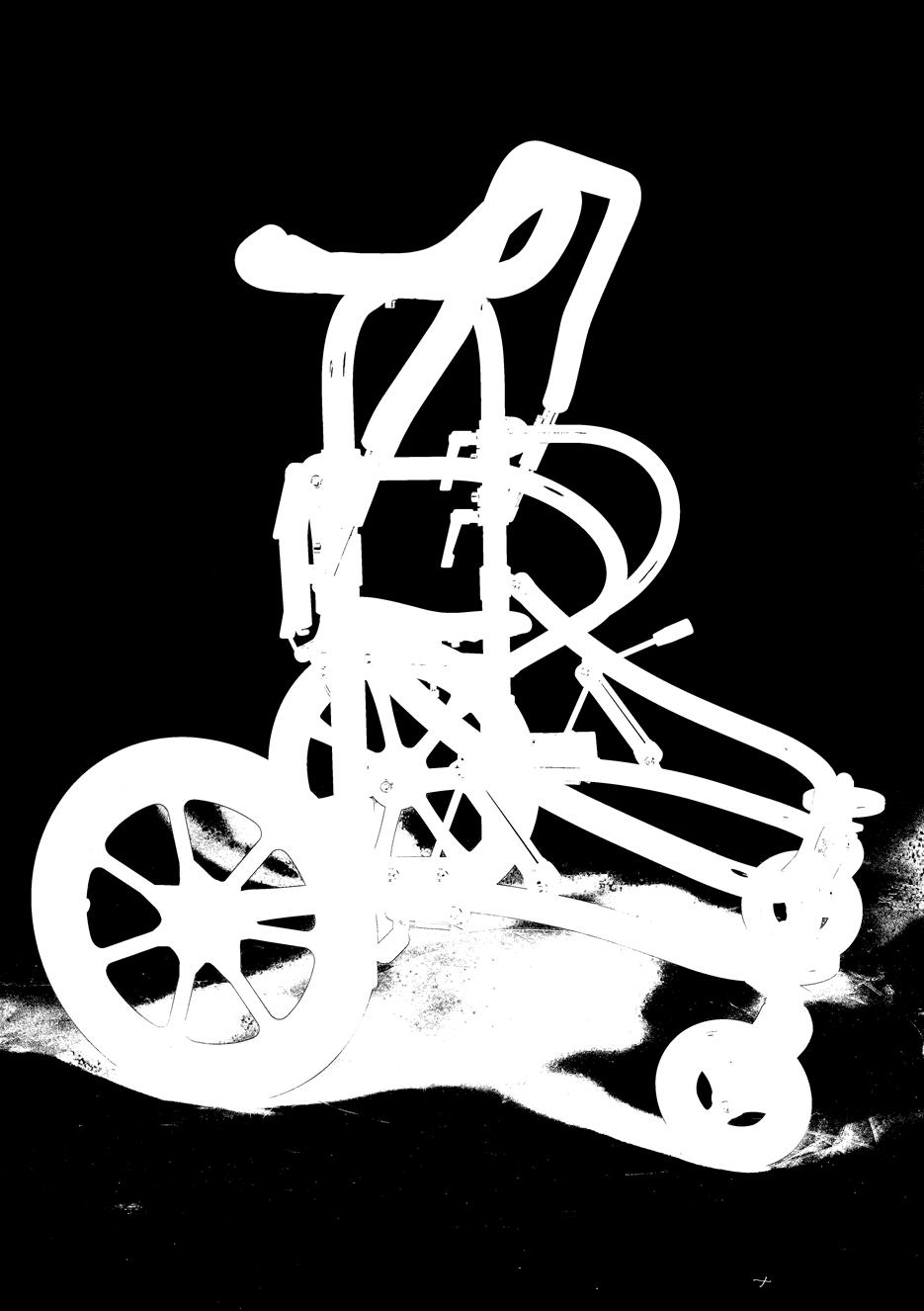
3 3 Introduction MEYWALK 2000 Small, Medium and Large are walking aids suitable for children from about 6 years old right up to adults, height from proximately 120 cm (47 ) to 200 cm (78 ). MEYWALK 2000 is intented for walking disabled who cannot stand up without support from a seat. MEYWALK 2000 can be adjusted to give a good and individually fitted support. The trunk support gives support to keep the torso upright and makes the user feel safe. The rear stop prevents the user from sliding off the seat, and the handlebar gives support to the arms. Using the integral lifting and lowering system the seat unit can be brought down to the height of a wheelchair seat, making it quick and easy to transfer the user over to the MEY- WALK 2000 and raise them up again. Both user and helper will find it much less tiring to get in and out of the MEYWALK 2000 than other walking aids. Due to the large wheels MEYWALK 2000 is suitable for both indoors and outdoors use. The Figure shows the names of some of the different parts of MEYWALK 2000 referred to in the text. Meywalk 2000 : : Handelbar : : Trunk support : : Upper tube : : Height marking : : Cone : : Seat tube : : Spanner grip : : Rear stop : : Lower tube : : Tilt bar : : Locking button : : Fender wheel : : Swivelling front wheel : : Brake : : Rear wheel


4 4 Prior to first use Prior to first use MEYWALK 2000 is supplied almost fully assembled. Check that the package contains the following parts: : : Bottom frame with wheels and brakes etc. : : Top part with seat and trunk support etc. Note that a 5 mm and a 6 mm Allen key is supplied with MEYWALK This is located under the rear stop. Joning the top part and bottom frame: Place the two springs in the top of the down tubes on the bottom frame and fit the top part into the two down tubes on the bottom frame. Remember to position the top part so the handlebar is in direction towards the swiveling front wheels. Adjustment of basic model Note that the seat height will be altered when the height of the trunk support is altered. The height of the trunk support and the seat is adjusted according the rulers on each side of MEYWALK Both adjustments are double secured. The spanner grips can easily withstand the load alone, but the adjustments can be extra secured with the Allen screws. This extra securing can be useful when MEYWALK 2000 is used by only one user or if there is a risk that a busybody loosens the spanner grips. two spanner grips. This enables the two rings to be slid up or down the upper tubes. Place the rings at the desired height using the height markings to ensure they are at the same height on both sides. At last retighten the spanner grips (and if necessary Allen screws). Set the seat height in the same way by loosening the top two Allen screws and then the top two spanner grips. This enables the seat tube to be slid up or down the upper tubes. Place the seat tube at the desired height using the height markings to ensure it is at the same height on both sides. At last retighten the spanner grips (and if necessary Allen screws). Mounting af accessories: A description of how to mount accessories, both those supplied with the walking aid and those acquired later, is given in the section: Mounting and adjustment of accessories. Trunk support and Seat height: The height of the trunk support is altered by loosening the bottom two Allen screws and then the bottom


 spanner will be needed here. After adjustment retighten the nuts.")
5 5 Trunk support locking: When closing the trunk support one can lock the two rear tubes by giving them a firm push downwards. In this way one can secure them from accidently slide open or being opened by a busybody! Spring Loading: The two springs inside the down tubes can be changed to give a harder or softer suspension. As a guideline, it should be possible to collapse the springs completely with the weight of the user. There are four different spring hardness s available, corresponding to the following minimum weights: Seat position and angle: The seat can be adjusted forwards or backwards by slackening the Allen screw below the seat fitting. When the desired position has been found, retighten the Allen screw. The angle of the seat can also be adjusted by slackening the four nuts under the seat. An 11 mm (7/16 ) spanner will be needed here. After adjustment retighten the nuts. white springs for at least 20 kg (45 b.), yellow springs for at least 45 kg (100 lb.), blue springs for at least 65 kg (145 lb.), red springs for at least 80 kg (175 lb.).


, on the MEYWALK 2000 Medium by about 15 cm (6 ), and on the MEYWALK 2000 Large by about 25 cm (10 ).")

6 6 Rear stop: The rear stop behind the seat can be adjusted in lengthways direction. First lift up the rear stop and tilt it backwards. This reveals an Allen screw inside the U-profile When the Allen screw is loosened, the rear stop can be slid forwards or backwards in the external tube. After adjustment, retighten the Allen screw. Handlebar: The handlebar is mounted on each side in a tube section located on a cone. The cones are fixed in position with Allen screws, and when these are loosened, the handle bar can be rotated around the cones. The handlebar can also be slid forwards or backwards in the two tube sections by additionally slackening the two Allen screws on the side of the handlebar. Once the right positions have been found, retighten the Allen screws. Getting in and out: MEYWALK 2000 has an integral lifting/lowering system, which facilitates getting in and out for the user. We recommend two helpers when getting the user in and out. Press in the lock fitting at the front of the MEYWALK 2000 and raise the tilt bar. On the MEYWALK 2000 Small this will lower the seat unit by about 13 cm (5 ), on the MEYWALK 2000 Medium by about 15 cm (6 ), and on the MEYWALK 2000 Large by about 25 cm (10 ). Then lift up and tilt backwards the rear stop and open the trunk support. When the user is in position on the seat, close the trunk support and rear stop and raise the seat unit by pressing the tilt bar down until it locks with an audible click. The integral gearing in the lifting/ lowering system means that downwards pressure need only be about one third of the user s weight. The brakes are parking brakes which function by directly blocking the rear wheels with a fitting which presses against the tire. To brake the walking aid, pull the brake levers all the way back until they come to a definite stop. In this position the brakes are self- locking. The brakes are released by pushing the brake levers forward again. Adjustment af brakes: First release the brakes by pushing the brake levers forwards. Now slacken the two nuts which fi x the brake mechanism to the bottom frame. This will require a 10 mm (13/32 ) spanner. The whole brake mechanism can now slide backwards or forwards. Set it with a clearance of 3-5 mm (0,1-0,2 ) between the brake fitting and the tire. Finally retighten the two nuts and test the brake action. Use of brakes:


7 7 Accessories: Height reduction fitting: The trunk support and seat height can also be reduced approximately 8 cm (3 ) with a set of height reduction fittings. These must be mounted in the hinge mechanism between the down tubes and the tilt bar. Unscrew the Allen screw heads and remove the tilt bar. Then fi t the two fittings over the hinge eyes on the down tubes and tighten. Finally slide the two bright internal hinge sleeves supplied into the hinge eyes on the fittings, fit the tilt bar over them and fasten with the Allen screw heads supplied. Anti-tip supports are mounted on each side by first removing the centercap on the outside of the rear wheel and unscrewing the nut from the bolt which pass through the wheel hub. Two 19 mm (¾ ) spanners will be needed for this. The longer bolt supplied with the anti-tip supports is fitted in the wheel hub instead of the existing bolt. Keep the old bolt safe in case the anti-tip supports later are removed. Then slide the U-fitting on the anti-tip support over the end of the frame where the wheel was mounted. Push the bolt through while placing a washer between the wheel and the U- fitting. Screw the nut back on. Remember to tighten firmly. Finally put on the centercap again. The height of the anti-tip supports from the ground is adjusted by slackening the counter nut on the adjusting screw. This will require a 13 mm (½ ) spanner. If necessary slacken the nut on the wheel bolt. The anti-tip support is tilted up so the head of the adjusting screw rests against the end of the frame and the adjusting screw is screwed forward or back to get the correct height. Then retighten the counter nut and the nut on the wheel bolt. Anti-tip:

 spanners.")


8 8 Swivel lock on front casters: The swivel locks are delivered mounted on two new front casters. For mounting first remove the two front wheels from the casters, use a 6 mm Allen key here. Remove the nutcap and unscrew the front casters from the bottom frame by unscrewing the lock nut on top of the fender wheel. This will require two 19 mm (¾ ) spanners. Then push the bolt on the new front casters into the bottom frame from below, place the tube fitting and the fender wheel on top of the bolt, and screw the lock nut back on. Make sure that the front wheels are pointing straight forward and parallel aligned, when the swivel locks are activated. At last install the front wheels in the front casters again and put on the nutcaps. Leg separation plate: The crossbar for the leg separation plate is mounted between the front wheels. The fittings at both ends of the crossbar are fastened with the supplied small top plates around the fittings holding the front wheels. At each side two Allen screws are screwed into the top plate from below through the holes in the fitting at the end of the crossbar. At the front the leg separation plate is equipped with a square tube, and this is slid into the square tube at the middle of the crossbar. The leg separation plate can be adjusted in height by loosening the hand screw on the crossbar. On the Small, there is a extra Washer. It has to stay on, when you mount the Leg separation plate.


9 9 Hip-pads: The hip-pads are mounted on the two upper tubes below the seat tube and above the two height adjustment rings. To mount the hip-pads first lift off the top part of MEYWALK 2000 from the bottom frame. At each side unscrew and remove the Allen screw and the spanner grip from the height adjustment ring and then remove the ring from the upper tube. The hip-pad is slid in over the upper tube and screwed together with the inner tube through the slit. Then mount the height adjustment rings at each side again with the included inner tubes. The hip-pads are adjusted away from or closer to the seat by loosening the hand screws on the spanner boxes which hold the square tubes. The height of the hip-pads are adjusted by loosening the Allen screws that hold the fittings on the upper tubes and slide these fittings up and down on the tube. After adjustment retighten the screws and grips. Leg guides: Leg guides for MEYWALK 2000 are delivered in a set of a left and a right rail. They are mounted on the inside at each side of the bottom frame. Before mounting unscrew the Allen screw heads at the lower end of the tubes connecting the tilt bar and the bottom frame.. The front end of the leg guides are fastened to these hinge connections with the supplied Allen screw heads and the longer threaded rods. The rear end of the leg guides are fastened to the bottom frame with the U-shaped plastic covered threaded rod.


10 10 Mounting and use of nonreverse brakes: The non-reverse brakes are mounted inside of the existing brakes. Use a 10 mm spanner to unscrew the nuts from the two bolts which fix the brake mechanism to the frame. The two bolts are removed and replaced with the supplied longer bolts. Then fit the non-reverse brake facing backwards over the two bolts. If the non-reverse brakes shall be used together with anti-tip supports the spacer fitting must be fitted. Next put back on the brake mechanism and screw the nuts back on. The non-reverse brake is adjusted so the curved fitting is pressed against the rear tire by the spring loaded button. When the correct position is found for the nonreverse brake - and also for the brake mechanism - retighten the nuts firmly. The non-reverse brakes can be deactivated by pushing the curved fitting forwards until the spring loaded button locks it in a position raised from the tire. Use a 10 mm (13/32 ) spanner to unscrew the nuts from the two bolts which fix the brake mechanism to the frame. The bolts are removed and replaced with the supplied longer bolts. If the drag brakes shall be used together with anti-tip supports the spacer-fitting must be fitted. Fit the drag brake over the two bolts with the hand screw facing forwards and screw up the nuts again. Finally remove the elastic band holding the roller in place. The drag brakes work by the roller at the back pressing into the tire. First slacken off the nut on the threaded shank behind the hand screw. Then turn the hand screw until the roller presses into the tire. Finally tighten off the nut against the drag brake housing. Use trial and error to find the best pressure against the tire. Mounting and use af drag brakes. The drag brakes are fitted on the outside of the existing brakes.

11 11 Maintenance Warning: : : MEYWALK 2000 is a therapy product - and should only be used as such! : : The spring system used in MEY- WALK 2000 can involve a certain risk of the walking aid toppling over if used by a very restless user. : : MEYWALK 2000 rolls very easy, and one should always consider potential dangers the user can roll over to. Therefore: Never leave the user in MEYWALK 2000 unattended! Warning: : : Always hold the tilt bar securely when a user is being lifted or lowered. Especially when opening the tilt bar to lower the user, be prepared for an upwards-directed force which gradually increases as the tilt bar rises. Never let go of the tilt bar in the middle of a lifting or lowering operation, even if taken by surprise by the heavy weight effect. CE-marking Meywalk 2000 is CE-marked. This warrants that Meywalk 2000 is conforming to all relevant safety requirements in Council Directive 93/42/EEC concerning medical devices. Meywalk 2000 is tested by Berlin Cert, Prüf- und Zertifi zierstelle für Medizinprodukte GmbH, an der Technischen Universität Berlin. With repeated use of detergent, the painted frame may gradually take on a matt appear ance. It can then be polished up with car polish. Follow the instructions on the polish. Checking for tightness: Regularly check that all bolts, screws and nuts are fully tightened and if necessary retighten. The product is not made with natural rubber latex. Warning: : : If fittings are removed, open tube ends may be revealed. These may have sharp inner edges and be dangerous for probing fingers. MEY- WALK 2000 is designed to avoid the necessity for open tube ends! If, however, a situation with open tube ends should arise, it is recommended that they are closed off with plastic plugs. Limitations on use: : : The maximum user weight permitted is 100 kg (220 lb.). : : The walking aid should only be used on flat, level and stable surfaces. Maintenance: The walking aid can be washed down with hot water and a normal detergent. However, the padding on the trunk support, handle bar and rear stop should be avoided.
12 Technical data Dimensions: Small Medium Large Length: 85 cm 95 cm 95 cm External width: 68 cm 70 cm 70 cm Internal width: 48 cm 48 cm 48 cm Seat height: cm cm cm Trunk support height: cm cm cm Trunk support options : 70, 90, 105 cm 70, 90, 105, 120, 130 cm 70, 90, 105, 120, 130 cm Weight: 22 kg 25 kg 26 kg Max load: 100 kg 100 kg 100 kg Materials Frame: Fittings: Padding: Seat cover: Powder-coated steel tubes Electrolytically galvanized steel Polyurethane foam Synthetic leather Diverse: Wheels: Soft solid rubber tires on synthetic rims with self-lubricating ball bearings. Colors: Green RAL 6018/ Navy Blue, RAL 5022 Heights are measured with half compression af springs Producent: Dealer Meyland-Smith A/S ٠ Mads Clausens Vej 1 ٠ 9800 Hjørring Phone: ٠ Fax.: ٠ info@meyland-smith.dk 141
User manual for. meywalk 2000 model Medium and Large
 User manual for meywalk 2000 model Medium and Large Page 2 Introduction These instructions for use contain information on the assembly and adjustment of MEYWALK 2000, how to maintain it, things to watch
MEYLAND-SMITH A/S EST User manual for MEYWALK 2000 model Medium and Large
 MEYLAND-SMITH A/S EST. 1901 User manual for MEYWALK 2000 model Medium and Large Introduction These instructions for use contain information on the assembly and adjustment of MEYWALK 2000, how to maintain
User manual. Model Mini, Small, Medium and Large
 User manual Model Mini, Small, Medium and Large 2 Contents Introduction..3 CE marking and labels...3 Safety precautions..3 Prior to first use 4 Meywalk 4 parts...4 Joining the top part and bottom frame.5
Nimbo Lightweight Posterior Posture Walker
 Nimbo Lightweight Posterior Posture Walker Assembly & Operating Instructions with optional Forearm Platforms with optional Pelvic Stabiliser Please read these instructions carefully before assembling or
Nitro Rollator
 Nitro Rollator Parts List 3 1 4 2 6 5 7 12 8 11 10 9 1. Handgrip 2. Adjustable tubing handgrip 3. Rear reflector on handgrip 4. Brake lever 5. Interlock button for handgrips 6. Back Rest 7. Seat 8. Bag
RECARO Monza Nova 2 Reha
 RECARO Monza Nova 2 Reha Group II III Instructions for assembly and use of the Reha version (supplement) RECARO Monza Nova 2 Reha / RECARO Monza Nova 2 Seatfix Reha 1a 1b 2a 2b 3a 3b 4a 4b 5a 5b 5c 5d
Rodeo Upgrades Q2 2014
 Rodeo Upgrades Q2 2014 New Rodeo Convaid is excited to announce new standard features and accessory options on the Rodeo Tiltin-Space Wheelchair. All new orders received as of June 19 2014 will have all
Nurmi Neo. Instructions for Use... 27
 Nurmi Neo Instructions for Use... 27 Instructions for Use for Nurmi Neo Table of Contents Page 1 General Information...28 1.1 Preface...28 1.2 Intended Use...28 1.3 Liability...28 1.4 CE Conformity...29
User Manual. English
 User Manual English User Manual Dear user, Thank you for choosing our product! We truly hope you will experience many pleasant moments and enjoy your Trionic Veloped both off-road and in the city. By choosing
RECARO Monza Nova 2 Reha / RECARO Monza Nova 2 Seatfix Reha
 RECARO Monza Nova 2 Reha / RECARO Monza Nova 2 Seatfix Reha Group II III Instructions for assembly and use of the Reha version (supplement) RECARO Monza Nova 2 Reha / RECARO Monza Nova 2 Seatfix Reha 1
Etac Prio. A comfort wheelchair with unique innovations.
 Etac Prio A comfort wheelchair with unique innovations. Etac Prio dynamic comfort By changing seat and back angles and adjusting the elevating leg supports, you can vary body position and pressure points,
Global West Suspension 655 South Lincoln Ave San Bernardino Ca Phone Fax Web address globalwest.
 Global West Suspension 655 South Lincoln Ave San Bernardino Ca. 92408 Phone 877-470-2975 Fax 909-890-0703 Web address globalwest.net Mustang coilover instruction sheets for 64-66 Kit includes the following
Migo. Migo Rollator Owner s Handbook. Y our Specialist Dealer. Issued: 10/2008
 Y our Specialist Dealer Migo Rollator Owner s Handbook Migo Issued: 0/2008 Drive Medical GmbH & Co. KG Leutkircher Straße 44 D-8836 Isny/Allgäu Phone +49 (0) 75 62-97 24-0 Fax +49 (0) 75 62-97 24-25 www.drivemedical.de
SIGMA. User Manual MB8100GB
 SIGMA User Manual Introduction Congratulations on your choice of your new lifting chair. Quality and functionality are keywords for all Handicare lifting chairs. For your own safety, and in order to get
EASyS Modular. Technical Manual. EASyS Modular Rehab stroller. Models. Accessories for EASyS Modular seat unit. Accessories for A and Q chassis
 EASyS Modular Technical Manual EASyS Modular Rehab stroller Models Accessories for EASyS Modular seat unit Accessories for A and Q chassis INDEX EASyS Modular,... is a rehab stroller with more head support,
2006 MINI Cooper SUSPENSION Wheels & Tires - Repair Instructions - Cooper (1.6L) R50/W10 & Cooper S
 R50/W10 & Cooper S") WHEELS 2002-05 SUSPENSION Wheels & Tires - Repair Instructions - Cooper (1.6L) R50/W10 & Cooper S 36 10 300 REMOVING OR INSTALLING FRONT OR REAR WHEEL NOTE: For Special Tool identification, see WHEEL AND
WHEELS 2002-05 SUSPENSION Wheels & Tires - Repair Instructions - Cooper (1.6L) R50/W10 & Cooper S 36 10 300 REMOVING OR INSTALLING FRONT OR REAR WHEEL NOTE: For Special Tool identification, see WHEEL AND
Aston Shower Commode Chair Owner s Handbook
 Aston Shower Commode Chair Owner s Handbook Aston Shower Commode (CWC003) Page 1 of 15 Introduction Aston Shower Commode Chair These instructions aid the user and/or carer about the safe and efficient
WHEELED WALKER OWNER S HANDBOOK
 CONTENTS 1. Contents 2. Introduction 3. Parts Description 4. Personal Safety 5. Adjustments for Comfort 6. Transportation & Assembly 7. Care and Maintenance 8. Brake Operation 9. Assembling the Walker
Phoenix Buggy User Instructions
 Phoenix Buggy User Instructions Issued 1 st March 2015 Introduction Welcome to the Phoenix Buggy User Guide. The Phoenix Buggy has been designed to provide a robust, transportable mobility solution for
ENIGMA SUPER DELUXE WHEELCHAIR
 1. CONTENTS 1. Contents 2. Introduction 3. Parts Description 4. Adjustment Features 5. Folding Back Mechanism 6. Disassembly and Folding 7. Using the Stepper Tube 8. Brake Operation 9. Lap Belt Operation
MARCY SMITH MACHINE SM Model SM Retain This Manual for Reference OWNER'S MANUAL
 NOTE: Please read all instructions carefully before using this product Table of Contents Safety Notice Hardware Pack Assembly Instruction MARCY SMITH MACHINE SM-4008 Parts List Warranty Ordering Parts
Aston Shower Commode Chair Owner s Handbook
 Aston Shower Commode Chair Owner s Handbook Aston Shower Commode (CWC003) Page 1 of 12 Introduction Aston Shower Commode Chair These instructions aid the user and/or carer about the safe and efficient
Mechanical Disc Brake
 (English) DM-BR0007-02 Dealer's Manual Mechanical Disc Brake BR-CX77 BR-CX75 BR-R517 BR-R515 BR-R317 BR-R315 BR-TX805 IMPORTANT NOTICE This dealer s manual is intended primarily for use by professional
190/195 Tilt Shower Commode User Manual
 ... 190/195 Tilt Shower Commode User Manual Healthline Products 1065 E Story Rd Winter Garden Florida 34787 Fax 407-656-5641 Toll Free: 800-987-3577 Product Information This series of rehab commodes offer
RECARO Monza Nova 2 Reha Monza Nova 2 Seatfix Reha Booster Seat. Instructions for assembly and use of the Reha version (supplement)
") RECARO Monza Nova 2 Reha Monza Nova 2 Seatfix Reha Booster Seat Instructions for assembly and use of the Reha version (supplement) 1a 1b 2a 2b 2c 3a 3b 4a 4b 2 5a 5b 5c 5d 5e 6a 6b 6c 6d 6e 6f 7a 7b 8a
RECARO Monza Nova 2 Reha Monza Nova 2 Seatfix Reha Booster Seat Instructions for assembly and use of the Reha version (supplement) 1a 1b 2a 2b 2c 3a 3b 4a 4b 2 5a 5b 5c 5d 5e 6a 6b 6c 6d 6e 6f 7a 7b 8a
Service manual. English. F5 Corpus
 Service manual English F5 Corpus Introduction The Service Manual is intended for technical personnel who maintain and repair power wheelchairs. It is important that anyone who performs maintenance and
User Manual. English
 User Manual English 1 User Manual Dear user, Thank you for choosing our product! We truly hope you ll enjoy a greater mobility with your Trionic Walker, and that you will experience many pleasant moments
Eco Buggy Instructions for Use...8
 Eco Buggy Instructions for Use...8 Q U A L I T Y F O R L I F E 1 2 3 4 5 6 7 8 9 10 11 12 13 14 15 16 17 Eco Buggy Instructions for Use Table of Contents Page Preface...9 Intended Use...9 Declaration of
COBRA Indoor base with gas pressure spring and 45 tilt function user manual
 COBRA Indoor base with gas pressure spring and 45 tilt function user manual - Partnering together to mobilise kids User manual for COBRA indoor base with gas pressure spring and 45 tilt Index 1 Common
RECARO Monza Nova 2 Reha Monza Nova 2 Seatfix Reha Booster Seat. Instructions for assembly and use of the Reha version (supplement)
") RECARO Monza Nova 2 Reha Monza Nova 2 Seatfix Reha Booster Seat Instructions for assembly and use of the Reha version (supplement) 1a 1b 2a 2b 2c 3a 3b 4a 4b 2 5a 5b 5c 5d 5e 6a 6b 6c 6d 6e 6f 7a 7b 8a
RECARO Monza Nova 2 Reha Monza Nova 2 Seatfix Reha Booster Seat Instructions for assembly and use of the Reha version (supplement) 1a 1b 2a 2b 2c 3a 3b 4a 4b 2 5a 5b 5c 5d 5e 6a 6b 6c 6d 6e 6f 7a 7b 8a
ASSEMBLY MANUAL 9GU - COMMERCIAL UPRIGHT BIKE
 ASSEMBLY MANUAL 9GU - COMMERCIAL UPRIGHT BIKE IMPORTANT SAFETY INSTRUCTIONS Read this Owner s Manual and follow it s instructions carefully before using the machine. Make sure that it is properly assembled
Rock N Roll Walker Instruction Manual
 Rock N Roll Walker Instruction Manual Read all instructions BEFORE assembly and USE of product. KEEP INSTRUCTIONS FOR FUTURE USE. Record the following information for quick reference. Note: Illustrations
Instruction Manual. Canada English Version
 Instruction Manual Canada English Version Product: Monterey child booster seat Model: 15000 Mfg. by: Diono Canada, ULC 50 Northland Road, Suite 400 Waterloo, Ontario N2V 1N3 Customer Service Tel: 519-725-1700
DELUXE SMITH MACHINE MSS Model MSS Retain This Manual for Reference
 NOTE: Please read all instructions carefully before using this product Table of Contents Safety Notice DELUXE SMITH MACHINE MSS-1280 Hardware Identifier Assembly Instruction Parts List Warranty Ordering
Turner PRO. User manual. BM61099 Rev B
 Turner PRO User manual BM6099 Rev B 06-09- Contents User manual - English - 4 Bruksanvisning - Svenska - 8 Brukermanual - Norsk - Brugsvejledning - Dansk - 6 Käyttöohje - Suomi - 0 Gebrauchsanweisung
Sovereign Wheelchair Instructions for Use. > Issue 1
 Sovereign Wheelchair Instructions for Use > Issue 1 Instructions for Use Contents 1 Important Safety Information...4 1.1 Safety in Vehicles...6 2 Indications / contraindications...7 3 Purpose...7 4 Scope
Wheelchair Safety, Maintenance and Operations Guide
 Wheelchair Safety, Maintenance and Operations Guide Back Arm Seat Tire Cross brace Axle Foot rest Hand rim Caster Index Page Introduction 3 Knowing equipment and be organised 3 Opening a wheelchair 4 Closing
Mounting Tools 2 Checking Clearances 3 Components 4-5 Mounting 6-21 Correct Method of Tensioning the Chain 22 Adjusting The Overall Dimension 23-24
 Mounting Tools 2 Checking Clearances 3 Components 4-5 Mounting 6-21 Correct Method of Tensioning the Chain 22 Adjusting The Overall Dimension 23-24 Maintenance 25 Repairing Main Body Patterns 26 Removal
Dealer Stamp. Rollator (R6 and R8) Assembly & Operating Instructions
 Assembly & Operating Instructions") The manufacturer reserves the right to alter without notice any weights, measurements or other technical data shown in this manual. All figures, measurements and capacities shown in this manual are approximate
The manufacturer reserves the right to alter without notice any weights, measurements or other technical data shown in this manual. All figures, measurements and capacities shown in this manual are approximate
Owner s Manual for the Travelite Electric Wheelchair
 Tel: 083 284 2973 Fax:086 232 5223 Email:ruan@cheapest-wheelchairs.co.za OR rosslyn@adpwheelchairs.co.za Web: www.cheapest-wheelchairs.co.za ORwww.adpwheelchairs.co.za Owner s Manual for the Travelite
Operators Manual. Customized Tilt-in-Space Wheelchair for Abby Miller. By: Katie Guineau, Julia Olczyk, Ben Marcus Team 11
 Operators Manual Customized Tilt-in-Space Wheelchair for Abby Miller By: Katie Guineau, Julia Olczyk, Ben Marcus Team 11 Abby Miller and the Miller Family Clinton, Illinois julie_miller.1367@yahoo.com
EZ LITE CRUISER. Service & Maintenance Manual
 EZ LITE CRUISER Service & Maintenance Manual Table Of Contents Introduction to the EZ Lite Cruiser 3 Identification of Components 4 Controller System Component Diagram 6 Controller System I/O Ports Detail
Etac Cross 5 and Cross 5 XL
 Etac Cross 5 and Cross 5 XL The new generation wheelchair with the optimum prerequisites for delivering comfort and excellent manoeuvrability. Etac Cross 5 when every little detail makes a big difference
SERVICE MANUAL. Seat system for electric wheelchair
 SERVICE MANUAL US VS Seat system for electric wheelchair How to contact Permobil Permobil Inc. USA 6961 Eastgate Blvd. Lebanon, TN 37090 USA Phone: 800-736-0925 Fax: 800-231-3256 Email: info@permobilusa.com
2 in 1 Rollator and Transit Chair M58203
 User Instructions 2 in 1 Rollator and Transit Chair M58203 Maximum Safe Working Load Please ensure these Instructions are fully read and understood before using this equipment. Retain these instructions
Apollo Tilt Wheelchair 18" and 20" Instruction Manual
 Apollo Tilt Wheelchair 18" and 20" Instruction Manual Table of Contents Contents Table of Contents... 2 Introduction... 3 Warning... 4 Safety Guidelines... 5 Parts of the Tilt Wheelchair... 6 Setup & Operation...
Operation Care Service
 HAWK ENTERPRISES OF ELKHART, INC Standard Floor Machine Owner s Manual Operation Care Service 13 175 RPM 1.5 HP 15 175 RPM 1.5 HP 17 175 RPM 1.5 HP 20 175 RPM 1.5 HP 13 160 RPM 1.5 HP XHD 15 160 RPM 1.5
1. Safety. Contents. Warning: The Maxi-Cosi Pearl can ONLY be used on a Maxi-Cosi FamilyFix base with IsoFix.
 Maxi-Cosi Pearl H Dear Parents, To ensure maximum protection and optimum comfort for your child, it is important that you read through the entire manual accompanying the product carefully and follow all
VECTRIX VX-2 SERVICE MANUAL. Version 1.0/May 2011 VECTRIX, LLC
 www.vectrix.com CONTENTS SECTION A: Tools 1 Tools Needed SECTION B: Mechanical Parts 1 Front Fairing 2 Front Console Cover 3 Speedometer Cover 4 Front Vertical Panel Cover-Lower 5 Front Vertical Panel
expandable booster Instruction Manual US Version
 expandable booster Instruction Manual US Version product: monterey expandable booster model series: 15000 mfg. by: Diono LLC 14810 Puyallup Avenue Sumner, WA 98390 Customer Care Tel: 1 (855) 463-4666 us.diono.com
Breezy EC Transport Wheelchair
 B r e e z y E C Tr a n s p o r t W h e e l c h a i r Breezy EC Transport Wheelchair O w n e r s M a n u a l READ BEFORE USE REVIEW THIS MANUAL Before using this chair you, and each person who may assist
bronco English user manual Bronco.indd :21:18
 bronco TM English user manual 2010 R82 /S. ll rights reserved. The R82 logo and the ronco are registered trademarks of R82 /S. 05.2011 ronco.indd 1 19-05-2011 13:21:18 Contents ronco... 3 Safety... 4 Warranty...
EASyS seating system - Ergonomic Adjustment and Safety System
 EASyS Technical Manual EASyS seating system - Ergonomic Adjustment and Safety System Models Positioning supports & harnesses Safety & protection Accessory for J chassis INDEX EASyS,... the ergonomic adjustment
Heavy Duty Miniature Quick-Change Applicator (Side-Feed Type) with Mechanical or Air Feed Systems
 with Mechanical or Air Feed Systems") Heavy Duty Miniature Quick-Change Applicator (Side-Feed Type) with Mechanical or Air Feed Systems Instruction Sheet 408-8040 30 NOV 17 Rev H Ram Assembly Ram Post Locking Screw Stock Drag Drag Release
Heavy Duty Miniature Quick-Change Applicator (Side-Feed Type) with Mechanical or Air Feed Systems Instruction Sheet 408-8040 30 NOV 17 Rev H Ram Assembly Ram Post Locking Screw Stock Drag Drag Release
TABLE OF CONTENTS CHAPTER 1: SAFETY PRECAUTIONS. 2.3 COMPONENTS in the Hardwars Kit COMPONENTS on the Product SETP SETP2...
 TABLE OF CONTENTS CHAPTER : SAFETY PRECAUTIONS. SAFETY PRECAUTIONS... CHAPTER 2: INSTRUCTIONS 2. DIMENSIONS... 2.2 LIST OF PARTS... 2.3 COMPONENTS in the Hardwars Kit.... 2.4 COMPONENTS on the Product...
BELT DRIVE PRO INDOOR CYCLING BIKE SF-B901B USER MANUAL
 BELT DRIVE PRO INDOOR CYCLING BIKE SF-B901B USER MANUAL IMPORTANT! Please retain owner s manual for maintenance and adjustment instructions. Your satisfaction is very important to us, PLEASE DO NOT RETURN
Heavy Duty Miniature Quick-Change Applicator (End-Feed Type) with Mechanical or Air-Feed Systems
 with Mechanical or Air-Feed Systems") Heavy Duty Miniature Quick-Change Applicator (End-Feed Type) with Mechanical or Air-Feed Systems Instruction Sheet 408-8039 02 JUN 16 Rev G Ram Post Wire Disc Insulation Disc Insulation Crimper Stripper
Heavy Duty Miniature Quick-Change Applicator (End-Feed Type) with Mechanical or Air-Feed Systems Instruction Sheet 408-8039 02 JUN 16 Rev G Ram Post Wire Disc Insulation Disc Insulation Crimper Stripper
K502, K503 & K504. Pacer Gait Trainer K502, K503 & K504 Product Manual
 K502, K503 & K504 Pacer Gait Trainer K502, K503 & K504 Product Manual Contents Important information 3 Safety messages 4-5 Recommended use 6 User and item dimensions 6 Check your order 7 Basic components
RH722 Instruction Manual
 5652-71352 RH722 Instruction Manual Introduction Thank you for purchasing this Car Mate INNO Winter. Before using your new Car Mate INNO Winter, please read through this instruction manual carefully, and
The Bike with Bite. Directions for use Notice D Utilisation Manual De Usario Gebruikershandleiding
 The Bike with Bite Directions for use Notice D Utilisation Manual De Usario Gebruikershandleiding Introduction (1.2) Dear Customer, We are delighted that you have chosen this top quality QUICKIE product.
PCBL 1610/ 1810 DE LUXE POWER WHEELCHAIR USER'S MANUAL Edition
 PCBL 1610/ 1810 DE LUXE POWER WHEELCHAIR USER'S MANUAL Edition 08.2010 mdh sp. z o.o. 90-349 Łódź, ul tymienieckiego 22/24 tel. (+48) 42 212 32 08 fax: (+48) 42 674 04 99 www.mdh.pl export@mdh.pl 1 TABLE
Basic Steel Rollator with 6" Wheels Knockdown Rolling Walker
 Basic Steel Rollator with 6" Wheels Knockdown Rolling Walker User Instructions & Warranty MDS86850ESKD Latex Free 2 Table of Contents Safety Instructions... 4 Rollator Parts List... 5 Assembly Instructions...
Owners Manual POWER PLUS MOBILITY OUR PRODUCTS WILL MOVE YOU
 Owners Manual POWER PLUS MOBILITY OUR PRODUCTS WILL MOVE YOU At Power Plus Mobility, we care! Thank you for choosing a wheelchair from Power Plus Mobility Inc. We are always improving in our ways to serve
BASIC STEEL ROLLATOR WITH 6" WHEELS KNOCKDOWN ROLLING WALKER
 BASIC STEEL ROLLATOR WITH 6" WHEELS KNOCKDOWN ROLLING WALKER USER INSTRUCTIONS & WARRANTY 100RA Product is not made with natural rubber latex. 2 Revised: 09/20/2016 Table of Contents Safety Instructions...4
Tri-Wheel Wheeled Walker
 Tri-Wheel Wheeled Walker Handle with lever brake Brake cable Handle height adjustment knob Removable basket and tray Large vinyl bag 8 inch (203 mm) wheels user guide Prior to use please read all instructions.
SERVICE MANUAL. Stander. Seat Assembly for Permobil Power Wheelchair
 SERVICE MANUAL US Stander Seat Assembly for Permobil Power Wheelchair How to contact Permobil Permobil Inc. USA 6961 Eastgate Blvd. Lebanon, TN 37090 USA Phone: 800-736-0925 Fax: 800-231-3256 Email: info@permobilusa.com
FORWARD-FACING USER MANUAL ECE R GROUP WEIGHT AGE kg 9m-4y
 FORWARD-FACING USER MANUAL ECE R44 04 GROUP WEIGHT AGE 1 9-18 kg 9m-4y 1 ! Thank you for choosing BeSafe izi Comfort. BeSafe has developed this seat with much care, to protect your child during the next
C15C C15C. Page 1 of 20
 2 x Lid Front Hinge 1135 8 x M8 Bolt 8 x M8 Washer (3mm Thick) 4 x M6 Large washers 4 x M6 Spring washers 4 x M6 x 40mm Bolts 6 x M6 20mm Bolts 6 x M6 Washers 20 x Screws 2 x Lid mount gas strut bracket
RECARO ProSport Reha. Instructions for assembly and use of the Reha version (supplement) Internet Download:
 Internet Download:") RECARO ProSport Reha Instructions for assembly and use of the Reha version (supplement) Internet Download: www.thomashilfen.us Dear RECARO ProSport Reha user, To make handling of your new children car
RECARO ProSport Reha Instructions for assembly and use of the Reha version (supplement) Internet Download: www.thomashilfen.us Dear RECARO ProSport Reha user, To make handling of your new children car
CHAINGUARD REGAL ST COLOR
 DESOTO/ REGAL HAULER PARTS LIST Item Part # Description QTY Item Part # Description QTY 1 11871 REFLECTOR KIT TRIKE 1 32 11764 FENDER BRACE 24" MWT 1 2 12199 SCREW #14 x 3/4 4 33 12176 NUT5/16-24 HEX 2
4ZA OWNERS MANUAL 4ZA OWNERS MANUAL FOR FAST FORK RACE
 4ZA OWNERS MANUAL 4ZA OWNERS MANUAL FOR FAST FORK RACE GENERAL Read this manual carefully before using your 4ZA FAST fork and setting up the integrated brakes. This complex and technically advanced product
Klöber Cato/Cato Plus Operating instructions. Sitting better.
 Klöber Cato/Cato Plus Operating instructions Sitting better. 1. 3. 4. 2. 5. 2 8. cat99/ cpl99 7. 6. 3 4 1. Seat height adjustment The seat height of your swivel chair can be continuously adjusted using
OPERATIONAL ADVICE WARNING: TO PREVENT SERIOUS INJURY, PLEASE READ AND UNDERSTAND ALL WARNINGS AND INSTRUCTIONS BEFORE USE.
 OPERATIONAL ADVICE WARNING: TO PREVENT SERIOUS INJURY, PLEASE READ AND UNDERSTAND ALL WARNINGS AND INSTRUCTIONS BEFORE USE. SAVE THIS MANUAL Keep this manual in a safe place for future reference. This
Operation Care Service
 HAWK ENTERPRISES OF ELKHART, INC Glide Floor Machine Owner s Manual Operation Care Service Hawk Enterprises 52744 Park Six Court Elkhart, IN 46514 Phone: 574-294-1910 Toll Free: 888-289-4295 Fax: 574-970-0289
A1062 & A1072 AUGER ASSEMBLY MANUAL. Read & understand all instructions pertaining to this auger prior to use!
 A1062 & A1072 AUGER ASSEMBLY MANUAL Read & understand all instructions pertaining to this auger prior to use! Safety Alert Watch for this ALERT Symbol. It identifies potential hazards to Personal SAFETY
Final Assembly Instructions: Runaround Cruiser
 Final Assembly Instructions: Runaround Cruiser Thank you for buying your new bicycle from L.L.Bean. Read these instructions carefully before beginning the final assembly. Prior to shipping, our expert
KidWalk KidWalk II Dynamic Mobility System
 OWNER S MANUAL KidWalk KidWalk II Dynamic Mobility System Manufactured By Prime Engineering A Division of Axiom Industries, Inc. Supplier Info 70111KWOM 2 TABLE OF CONTENTS This owner s manual is organized
MARCY SMITH MACHINE SM Model SM Retain This Manual for Reference OWNER'S MANUAL
 NOTE: Please read all instructions carefully before using this product Table of Contents Safety Notice Important Assembly Information MARCY SMITH MACHINE SM-4008 Care and Maintenance Parts List Warranty
Be Strong. NS 200X. Assembly Manual. Model: NS 200X. P/N: Rev A (10/04/2006)
") Be Strong. Assembly Manual NS 00X Model: NS 00X P/N: 00-700 Rev A (0/0/00) TABLE OF CONTENTS Before You Assemble... 3 Product Specifications... Product Features... Parts List / Box Contents... 5 Exploded
Be Strong. Assembly Manual NS 00X Model: NS 00X P/N: 00-700 Rev A (0/0/00) TABLE OF CONTENTS Before You Assemble... 3 Product Specifications... Product Features... Parts List / Box Contents... 5 Exploded
MARCY PLATINUM MP-3500 HOME GYM
 NOTE: Please read all instructions carefully before using this product Table of Contents Safety Notice Hardware Identifier MARCY PLATINUM MP-3500 HOME GYM Assembly Instruction Parts List Warranty Ordering
Mighty Mack Wheeled Walker
 Mighty Mack Wheeled Walker Handle with lever brake Backrest Handle height adjustment knob Brake cable Extra wide padded seat Shopping basket Side brace 7 inch (180 mm) wheels user guide Prior to use please
CHAINGUARD REGAL ST COLOR
 DESOTO/ REGAL HAULER PARTS LIST Item Part # Description QTY Item Part # Description QTY 1 11871 REFLECTOR KIT TRIKE 1 32 11762 FENDER BRACE 20" MWT 1 2 12199 SCREW #14 x 3/4 4 11764 FENDER BRACE 24" MWT
COIL-OVER SUSPENSION SYSTEM
 Page 1 of 11 PART NUMBER: 220.50.631X, 220.60.631X INSTRUCTION SHEET NUMBER: 920.65.9800A COIL-OVER SUSPENSION SYSTEM APPLICATION: 1997-2013 CORVETTE PACKAGE CONTENTS: Coil-Over Assembly - Front Right
INSTRUCTION MANUAL STANDING WHEELCHAIR. KARMAN HEALTHCARE INC. City of Industry, CA
 INSTRUCTION MANUAL STANDING WHEELCHAIR KARMAN HEALTHCARE INC. City of Industry, CA 91748 www.karmanhealthcare.com **Karman Healthcare Inc. Recommends Patient Seek Physicians Counsel Before Purchase TABLE
20 TONNE HYDRAULIC PRESS MODEL NO: CSA20FBT
 20 TONNE HYDRAULIC PRESS MODEL NO: CSA20FBT PART NO: 7614058 OPERATION & MAINTENANCE INSTRUCTIONS WARNING: Read these instructions before using the press GC0516 INTRODUCTION Thank you for purchasing this
Caring for Your Manual Wheelchair
 Caring for Your Manual Wheelchair Your wheelchair is a machine that will help you to be more active and mobile. Check the wheelchair often to be sure that it is working well and safely. There may be a
Place these instructions in vehicle s glove box after installation is complete. Clean Tonneau Cover with a mild detergent and water solution.
 Place these instructions in vehicle s glove box after installation is complete Installation Time: Approx. 60 Minutes Care Instructions: Clean Tonneau Cover with a mild detergent and water solution. Do
2013 RT / 2014RT / 2015 RT - Shock Spring Adjuster Installation Instructions
 2013 RT / 2014RT / 2015 RT - Shock Spring Adjuster Installation Instructions Billet Aluminum Adjusters (2) Shock Spring Compressors (Optional) Spanner Wrench (1) BajaRon Decals Not Shown (4) Adjuster Scuff
Positioner Mount Assembly
 Read all instructions carefully & check all components are present before discarding packing materials. Assembly Procedure Assembly Procedure... 1 Identify the Parts... 2 The Frame Clamp Assembly... 2
Advancement Chair. R901, R902, & R903 Product Manual
 Advancement Chair R901, R902, & R903 Product Manual Contents Warnings and Important Information 3 Recommended Use 4 User and Item Dimensions 4 Assembly and Adjustment Information 5 Maintenance 14 Cleaning
Uplift Power Seat Users Guide
 Safety Precautions 1. Use the Uplift Power Seat only in armchairs or sofas with at least one armrest for optimum stability when sitting or rising. 2. Uplift Power Seat is not intended for use in rocking
Electrically Assisted Pedal Cycles. Assembly Instructions
 Electrically Assisted Pedal Cycles Assembly Instructions Version 1 December 2005 Introduction Thank you for buying a PowaCycle Edinburgh electric bike. We hope it brings you many hours of enjoyment. For
Expedition Wheelchair.
 Expedition Wheelchair www.drivedevilbiss.co.uk Expedition Wheelchair Owner s Handbook (Page 1) Contents 1. Contents 2. Introduction 3. Parts Description 4. Leg Rest Operation 5. Folding Back Mechanism
PET UNIT DOSE TABLE INSTALLATION MANUAL FN: Rev A 1/18
 PET UNIT DOSE TABLE INSTALLATION MANUAL 042-448 FN: 09-243 Rev A 1/18 Pet Unit Dose Table This manual covers installation procedures for the following products: 042-448 Table, PET, Unit Dose 2 Biodex Medical
Invacare Action 1 NG S E R V I C E M A N U A L
 Invacare Action 1 NG S E R V I C E M A N U A L ( M A I N T E N A N C E A N D A D J U S T M E N T ) The procedures in this manual MUST be performed by a qualified technician. 1638511- A December 2016 TABLE
bronco English user manual R82 A/S. All rights reserved. The R82 logo and the Bronco are registered trademarks of R82 A/S.
 bronco TM English user manual 2004 R82 /S. ll rights reserved. The R82 logo and the ronco are registered trademarks of R82 /S. 04.2007 Contents ronco... 3 Safety... 4 uarantee... 4 Tools... 4 Washing...
Owners manual. Öhlins Superbike front fork FG 170
 Owners manual Öhlins Superbike front fork FG 0 Including: Setting up your fork Changing springs and seals Service the fork Trouble shooting Technical info Spare parts & tools Öhlins super bike front fork
Hawk Enterprises of Elkhart THE BRUTE Owner s Manual
 Hawk Enterprises of Elkhart THE BRUTE Owner s Manual Operation Care Service COMMERICAL/INDUSTRIAL DUTY STONE RESTORATION MACHINE 13, 15, 17, 20 165 RPM 1.5 HP 180 FRAME TOTALLY ENCLOSED FAN COVERED MOTOR
6 x 10 Belt Disc Sander
 6 x 10 Belt Disc Sander FOR HELP OR ADVISE ON THIS PRODUCT PLEASE CALL OUR CUSTOMER SERVICE HELP LINE : 01509 500400 THE MANUFACTURER RESERVES THE RIGHT TO ALTER THE DESIGN OR SPECIFICATION TO THIS PRODUCT
K710 Product Manual. Support Station. K710 Product Manual
 K710 Product Manual Support Station K710 Product Manual Contents Important information 2 Safety messages 3 Recommended use 4 Item dimensions 5 Check your order 6 Installation 6 Basic components 7 Accessories