INNOVATION IS OUR POWER.
|
|
|
- Jodie Houston
- 5 years ago
- Views:
Transcription


1 MANUAL 2019 EN

2

3


4 INNOVATION IS OUR POWER. Wöhner develops system solutions for the electro-technical market. For over 90 years, the Wöhner name has been synonymous with impressive technical achievements and innovations. Today, the Wöhner Group is established worldwide as a specialist for international fuse and busbar systems in the field of power distribution, control technology and renewable energies. Innovations, short response times and the best possible customer service are the factors which enable us to compete in the international market. To help us meet these challenges, we are investing worldwide and continuously searching for skilled employees.


5 Wöhner offers in excess of 2400 different products. The naming structure consists of a combination of basic system and product family names. The individual products can be used for one or more systems. BASIC SYSTEMS PRODUCT FAMILY CrossBoard Panel AMBUS Busbar mounted fuse-holder BROOME10 Power supply unit CAPUS Switch-disconnector CRITO Connection terminal plate 30Compact Get excited about new systems from Wöhner CUSTO Busbar mounted fuse-base EQUES Busbar adapter MOTUS Hybrid motor starter OMUS Hybrid switch 60Classic 185Power QUADRON NH busbar mounted fuse-switchdisconnector SECUR D0 switch-disconnector with fuses TRITON Panel mounted fuse-base
6 1 CrossBoard 125 A (power distribution system) Overview 1 CrossBoard, connection modules 1.1 NH fuse-switch-disconnector, power supplies 1.1 Hybrid motor starters, hybrid switches 1.2 Adapter technology, switch-disconnectors-fuse Adapter technology Compact 200 A / 360 A (30 mm / 60 mm busbar system) Overview 2 Busbar support, covers, power supplies, busbars 2.1 Busbar connection technology 2.2 Busbar adapter technology 2.3 Hybrid motor starters, hybrid switches 2.3 D0 busbar mounted fuse-bases 2.4 NH busbar mounted fuse-switch-disconnectors pole system: Busbar supports, connection technology 2.5 Busbar adapter technology Classic 630 A / 800 A / 2500 A (60 mm busbar system) Overview 3 Busbar supports, power supplies, covers, busbars Busbar connection technology Busbar adapter technology Hybrid motor starters, hybrid switches 3.16 D and D0 busbar mounted fuse-bases D0 busbar mounted switch-disconnectors-fuse Busbar mounted fuse-holders for cylindrical fuses 3.20 Busbar mounted fuse-holders for Class J and Class CC fuses 3.21 NH busbar mounted fuse-bases 3.22 NH busbar mounted fuse-switch-disconnectors NH busbar mounted switch-disconnectors-fuse Speed Busbar mounted switch-disconnectors Speed NH in-line fuse-disconnectors 3.29 Busbar systems - special solutions Power 2500 A (185 mm busbar system) Overview 4 Busbar supports, busbars, touch-safe protection modules, system shroudings 4.1 Busbar connection technology 4.2 Busbar adapter technology NH in-line fuse-switch-disconnectors NH-switch-disconnectors-fuse Centre feed unit (feeding system) Overview 5 Centre feed units with double-t and triple-t section busbars Centre feed units with double-t, triple-t and TCC section busbars Panel (devices for panel mounted and DIN rail) Overview 6 Hybrid motor starters 6.1 D0 fuse-bases D0 switch-disconnectors-fuses 6.4 D fuse-base 6.5 Fuse-holders for cylindrical fuses IEC, UL / CSA Fuse-holders for cylindrical fuses (photovoltaics) 6.7 Fuse-holders for cylindrical fuses Class CC 6.9 Fuse-base for fuses Class J 6.10 NH fuse-bases NH fuse-switch-disconnectors NH switch-disconnectors-fuse Speed 6.17, 21 Switch-disconnectors up to 160 A Switch-disconnectors up to 3150 A Changeover switches Accessories D0 fuses and accessories D fuses and accessories NH fuses and accessories Cylindrical fuses 10x38, 14x51 and 22x Cylindrical fuses Class CC and Class J Insulators 7.12 Laminated copper busbars Connection bars, connecting terminals Appendix Terms of delivery and payment 8.1 Wöhner worldwide 8.1 Technical information Index
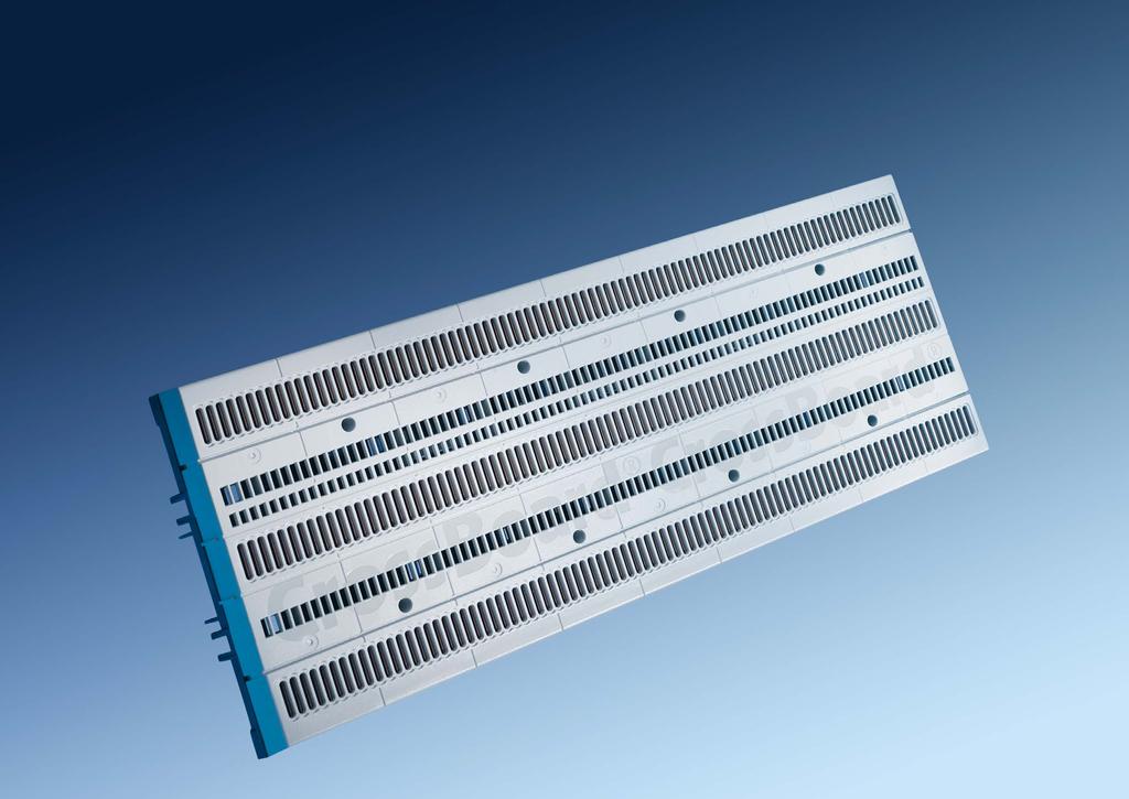
7 CrossBoard 1


8 CrossBoard 125 A power distribution system 1 POWER DISTRIBUTION SYSTEM CrossBoard the global basic system CrossBoard Tool-free mounting combined with outstanding safety thanks to integrated touch-safe protection make CrossBoard by Wöhner the ideal system solution for power distribution equipment up to 125 A. The user can quickly and easily snap components onto the global basic system. The feeding of the system can be achieved via connection modules or the NH fuse-switch-disconnector 000. CrossBoard is suitable mainly for applications in machine tool and plant engineering. The modular structure ensures that the systems are clearly structured and, when necessary, easy to change or expand. Motors of up to 4 kw can be supplied directly from the CrossBoard using the MOTUS hybrid motor starter. The OMUS hybrid switch is available for resistive loads with its low power dissipation and high life expectancy thanks to hybrid switch technology. The power supply for supplying the devices with control voltage can be integrated directly on the CrossBoard.
 600 V AC / 600 V DC (UL) UL listed Connection modules for")


9 CrossBoard 125 A power distribution system 1 CrossBoard CRITO CrossBoard EQUES CrossBoard Connection and mounting platform for all components. rated current 125 A equipment width: 225 or 405 mm height 160 mm short-circuit capacity Ipk=25 ka rated voltage: 690 V AC / 600 V DC (IEC) 600 V AC / 600 V DC (UL) UL listed Connection modules for CrossBoard. Particularly simple, safe and convenient mounting. rated current: 80 A or 125 A equipment width: 22.5 or 45 mm connection cables: mm² or 6-50 mm² equipment width 22.5 mm with SnapLock technology for tool-free mounting of cables with CRITO 22.5 mm UL listed The EQUES universal adapter can be used to mount measuring and monitoring relays. rated current 16 A equipment width 22.5 mm connection cross-section 2.5 mm² for 1- to 3- pole devices fuse compartment for 10x38 Class CC fuses up to max. 16 A UL listed EQUES CrossBoard EQUES CrossBoard EQUES CrossBoard EQUES CrossBoard Adapter of 18 mm width, suitable for mounting miniature circuit breakers from various manufacturers. rated current: 16 A or 63 A equipment width 18 mm 1 fixed mounting rail connection cables: 2.5 mm² or 10 mm² can be combined into 1- to 4-pole adapters via accessories UL listed Adapter for mounting motor protection devices with a fixed DIN rail. rated current up to 32 A equipment width 45 mm connection cables: 2.5 mm² or 6 mm² UL listed The EQUES CrossBoard adapters are available for simple mounting of motor starter combinations from various manufacturers. rated current up to 45 A equipment width 45 mm adjustable mounting rail connection cables: 2.5 mm², 4 mm², 6 mm² or 10 mm² accessories for mounting of contactors UL listed Adapter, 90 mm wide, to accept circuit breakers of different manufacturers. rated current 160 A equipment width 90 mm fixing adjustable to the circuit breaker tool-free mounting of the adapter UL listed OMUS CrossBoard MOTUS CrossBoard BROOME10 CrossBoard QUADRON CrossBoard Hybrid switch for switching resistive loads. The hybrid switch technology minimises power dissipation. continuous current up to 25 A equipment width 36 mm 4 integrated functions: energy supply, fuse protection, monitoring and switching 3-pole or 1-pole switching UL listed Hybrid motor starter with integrated functions: direct and reversing starter, overload protection and emergency stop function. Significantly reduced space requirements and wiring costs. 3 design versions: up to 0.6 A, up to 2.4 A and up to 9 A equipment width 22.5 mm hybrid switch technology up to 30 mil. switching cycles UL listed Power supply for direct connection on the CrossBoard. output voltage 24 Vdc output current 10 A equipment width 45 mm no back-up fuse required series and parallel connection to expand the current and voltage range UL listed NH fuse-switch-disconnector 000 with only 49.5 mm equipment width. For feeding the CrossBoard or a fused tap. rated current 125 A for NH fuse-links 000 equipment width 49.5 mm box terminals 6-50 mm² connection at top and bottom utilisation category AC 22B, AC 21B

10 1 1 CrossBoard 125 A power distribution system 1 2 CrossBoard - Basic systems 3-pole up to 125 A MOTUS CrossBoard - OMUS CrossBoard Hybrid switch for switching of inductive and resistive loads CrossBoard power distribution system, touch-safe protected with CrossLink interface Rated current Width Height CrossBoard A CrossBoard MOTUS CrossBoard hybrid motor starter, 3-pole, with reversing function and CrossLink interface Rated current Width Height electronic unit A direct and reversing starter 0.6 A electronic unit A direct and reversing starter 2.4 A electronic unit A direct and reversing starter 9 A Replacement fuse, for MOTUS CrossBoard fuse 16 A for version 0.6 A and 2.4 A fuse 20 A for version 9 A fuse 30 A for version 9 A for motors with heavy-duty starting CRITO CrossBoard connection module, 3-pole, with SnapLock connection technology, cover cap and CrossLink interface For use up to max. Width Height with integrated spring terminals mm², AWG A with box terminals 6-50 mm² / AWG 10 - AWG A QUADRON CrossBoard fuse-switch-disconnector, 000, with CrossLink interface Rated current Width Height box terminal 125 A OMUS CrossBoard hybrid switch, 3- or 1-pole switchable, for resistive loads, with CrossLink interface Rated current Width Height electronic unit, 25 A (IEC) 25 A electronic unit, 20 A (UL) 20 A supplied with both load and control plug Replacement component, for OMUS CrossBoard 3-pole load plug with spring terminals pole load plug with screw terminals pole control plug with spring terminals Replacement fuse, for OMUS CrossBoard cylindr. fuse link 32 A cylindr. fuse link 30 A, time delay BROOME10 CrossBoard power supply, with CrossLink interface Nominal output current Width Height 24 V DC, with push-in terminals 10 A parallel connection for increased current and series connection for increased voltage possible New product New product
11 EQUES CrossBoard - Adapters 16 A - 63 A 1-pole, 3-pole 1 3 EQUES CrossBoard - Adapters 16 A A 1-pole, 3-pole CrossBoard 125 A power distribution system 1 4 EQUES CrossBoard adapter and component support, 1-pole, for MCBs, with CrossLink interface Rated current Width Height as 1 1 x mounting rai it a s 1 2 mm 16 A as 2 1 x mounting rai it a s 1 2 mm 16 A as 1 x mounting rai it a s 1 2 mm 16 A as 1 1 x mounting rai it a s 1 mm 63 A as 2 1 x mounting rai it a s 1 mm 63 A as 1 x mounting rai it a s 1 mm 63 A it out tri a onn tion 1 x mounting rai EQUES CrossBoard adapter, basic version, with CrossLink interface Rated current Width Height 1 x mounting rai it a s 1 2 mm 16 A x mounting rai it a s 1 mm 32 A EQUES CrossBoard adapter with fuse-carrier 16 A, with leads AWG 14 (2,5 mm²), with CrossLink Interface Rated current Width Height 1 x mounting rai it fus arri r 1 x ass 16 A EQUES CrossBoard adapter and component support, comfort version, with CrossLink interface Rated current Width Height 1 adjustable mounting rail, with leads AWG 14 (2.5 mm²) 16 A adjustable mounting rail, with leads 160 mm long AWG A (2.5 mm²), for devices with spring terminal technology 1 adjustable mounting rail, with leads AWG 14 (2.5 mm²) 25 A adjustable mounting rail, with leads AWG 10 (6 mm²) 32 A adjustable mounting rail, with leads 160 mm long AWG A (6 mm²), for devices with spring terminal technology 1 adjustable mounting rail, with leads AWG 8 (10 mm²) 45 A without electrical connection, 1 adjustable mounting rail Extension component, for adapter comfort version Article Width extension module for direct starters 40 mm extension extension set for reversing starters Accessories, for adapter comfort version mounting rail 45 mm positioning piece for Siemens S00 and S positioning piece for Eaton PKZ EQUES CrossBoard Adapter, 160 A, with CrossLink Interface Article Width universal version up to 160 A, mounting distance 25 mm universal version up to 160 A, mounting distance 30 mm New product Accessories.7; 7.8; 7.9 New product Accessories.7; 7.8; 7.9
12 30Compact 2


13 30Compact 200 A / 360 A 30 mm / 60 mm busbar system 2 30 MM / 60 MM BUSBAR SYSTEM 30Compact Compact busbar system for control technology and power distribution equipment up to 360 A The 30Compact busbar system is the ideal solution for distribution boards with a rated current up to 360 A. The installation height of just 160 mm allows a particularly compact system to be realised. The 30Compact busbar system offers a clear space advantage compared to the 60Classic busbar system. Especially with smaller systems and their lower power requirements, valuable space can be saved within the cabinet. For such applications the 30Compact is the ideal system.


14 30Compact 200 A / 360 A 30 mm / 60 mm busbar system 2 30 MM / 60 MM BUSBAR SYSTEM 30Compact 30Compact 5-pole space-saving solution for distribution systems with miniature circuit breakers In addition to the 3 phases, N and PE conductors can be arranged between the phase bars maintaining an installation height of just 160 mm. For distribution systems up to 200 A, 5-pole systems can be built in a space-saving manner with convenient connection. For connection, 1-pole modules for conductors up to 120 mm² or adapters for switch-disconnectors are available. The adapters for mounting miniature circuit breakers up to 63 A can be variably adjusted to the tapping of the different phases and combined as required to form multipole adapters.

 busbars with end cover UL listed, in connection with 3-pole installation Connection module with spring terminals for 30Compact")
15 30Compact 200 A / 360 A 30 mm / 60 mm busbar system 2 Busbars 30Compact Busbar support 30Compact CRITO 30Compact CRITO 30Compact 12 x 5 mm for 3- and 5-pole applications 12 x 10 mm for 3-pole applications tin-plated versions proven load current capacity proven short-circuit capacity UL listed Busbar support for easy and safe installation. 3-pole with 60 mm distance between busbar centres, also for UL-compliant applications. 3- to 5- pole busbar support for 12 x 5 and 12 x 10 mm (3-pole only) busbars with end cover UL listed, in connection with 3-pole installation Connection module with spring terminals for 30Compact allows especially simple, safe and convenient mounting. rated current max. 80 A equipment width 20 mm connection area mm² spring-loaded technology for tool-free conductor connection UL listed Connection terminal plates. Convenient terminals for drill-less connection technology. Integrated touch-safe protection, complies with air and creepage distances as per UL. rated current up to 480 A equipment width: 54 or 90 mm connection area: 6-50 mm² or mm² lam. CU bars UL listed EQUES 30Compact EQUES 30Compact MOTUS 30Compact OMUS 30Compact Adapter of 18 mm width, suitable for mounting miniature circuit breakers from various manufacturers. rated current: 32 A or 63 A equipment width 18 mm 1 fixed mounting rail connection cables: 6 or 10 mm² can be combined into 1- to 4-pole adapters via accessories side, PE and N extension modules are available The EQUES 30Compact busbar adapters are available for easy mounting of motor starter combinations from various manufacturers. rated current: up to 32 A or up to 63 A equipment width: 45 or 54 mm adjustable mounting rail connection cables: 6 or 10 mm² side-mounted module, 9 mm wide UL listed Hybrid motor starter with integrated functions: direct and reversing starter, overload protection and emergency stop function. Significantly reduced space requirements and wiring costs. 3 design versions: up to 0.6 A, up to 2.4 A and up to 9 A equipment width 22.5 mm hybrid switch technology up to 30 mil. switching cycles UL listed Hybrid switch for switching resistive loads. The hybrid switch technology minimises power dissipation. continuous current up to 25 A equipment width 36 mm 4 integrated functions: energy supply, fuse protection, monitoring and switching 3-pole or 1-pole switching UL listed BROOME10 30Compact CUSTO 30Compact QUADRON 30Compact Power supply for direct connection, including adapter with CrossLink Technology. output voltage 24 Vdc output current 10 A equipment width 45 mm no back-up fuse required series and parallel connection to expand the current and voltage range UL listed Busbar mounted fuse-base for D02 fuses. rated current 63 A equipment width 36 mm connection area mm² Extra-slim NH fuse-switchdisconnector for NH 000 fuses with CrossLink Technology. Tool-free mounting, spring-loaded contact and offering a particularly safe connection, changing the direction of outgoing connection is easy and safe. rated current 125 A for NH fuse-links 000 equipment width 49.5 mm box terminal 6-50 mm² utilisation category AC 22B, AC 21B connection at top and bottom


16 30Compact - Busbar systems 3-pole systems, system height 160 mm 2 1 CRITO 30Compact - Connection technology 1-pole and 3-pole, system height 160 mm 30Compact 200 A / 360 A 30 mm / 60 mm busbar system 2 2 Busbar support, with end cover For busbar for busbar 3-pole 12 x 5 and 12 x UL spacer suitable for Universal connection terminal, 1.5 to 120 mm² For busbar Connection min. max. Terminal space W x H For use up to max. flat busbars mm mm², AWG x A mm², AWG x A mm², AWG 14-2/0 14 x A mm², AWG 4 - MCM x A flat busbars 1 mm mm², AWG x A mm², AWG x A flat busbars 1 mm an s tion busbars mm², AWG 14-2/0 14 x A mm², AWG 4 - MCM x A Cover cap, for universal connection terminals terminal cover, for and BROOME10 30Compact power supply, with CrossLink Technology Nominal output current Width Height 24 V DC, with push-in terminals 10 A parallel connection for increased current and series connection for increased voltage possible Copper busbar, flat busbar tin at Length Cross-section mm² 12 x x for current carrying capacity of the busbars visit partial lengths on request Cover section, for 3-pole busbar systems 0.70 m long Brace terminal, up to 150 mm², for round conductors For busbar Connection min. - max. Terminal space W x H 12, 15, 20 x 5, 10 * mm², AWG 2 - MCM 300, lam. Cu x 5-10 * when using aluminium conductors, observe the maintenance instructions (see 8.2) Connection module, 3-pole, with spring terminals, with cover cap For use up to max. For busbar Connection Width For use up to max. 12 x 5, 10 with integrated spring terminals mm², AWG 14-6 Connection terminal plate, 3-pole, with cover cap 12 x 5, mm², AWG 10-2/0, lam. Cu. 7-9 x x 5, mm², AWG 2 - MCM 300, lam. Cu x 5-10 Busbar connecting terminal, for identical busbars For busbar System spacing Width For use up to max. 20 x A A A A , 15, 20 x 5, A , 15, 20 x 5, A pieces required for a 3-pole connection, use and as cover Mount for cover section, for 3-pole busbar systems for Busbar cover, 1 m long for 12 x 5 busbar, 1 m long for x 5 busbar, 1 m long for x 10 busbar, 1 m long New product Accessories.5

 1 adjustable mounting rail 45 160 4 19.8 05 32590 Busbar adapter, 63 A, with leads AWG 8 (10 mm²) 1 adjustable mounting rail 54 160 4 21.")
17 EQUES 30Compact - MOTUS 30Compact - OMUS 30Compact busbar adapter and hybrid switch for switching of inductive and resistive loads 2 3 CUSTO 30Compact - QUADRON 30Compact 3-pole fuse-base and fuse-switch-disconnector, system height 160 mm 30Compact 200 A / 360 A 30 mm / 60 mm busbar system 2 4 Busbar adapter with fuse carrier, 16 A, with removable top section, with leads AWG 14 (2.5 mm²) Width Height 1 x mounting rai it fus arri r 1 x ass D0 busbar mounted fuse-base, with touch-safe protection Width Height E 18 / 63 A Busbar adapter, 32 A, with leads AWG 10 (6 mm²) 1 adjustable mounting rail Busbar adapter, 63 A, with leads AWG 8 (10 mm²) 1 adjustable mounting rail Busbar adapter, 160 A, connection to system at the top for Siemens 3VA10, 11 and 3VT Side-mounted module, for busbar adapters 32 A to 63 A for and Hybrid motor starter, MOTUS 30Compact, 3-pole, with reversing function and CrossLink Technology A direct and reversing starter A direct and reversing starter A direct and reversing starter Replacement component, for MOTUS 30Compact electronic unit A direct and reversing starter electronic unit A direct and reversing starter electronic unit A direct and reversing starter busbar adapter base with CrossLink interface fuse 16 A for version 0.6 A and 2.4 A fuse 20 A for version 9 A fuse 30 A for version 9 A for motors with heavy-duty starting Hybrid switch, OMUS 30Compact, 3- or 1-pole switchable, for resistive loads, with CrossLink Technology Width Height 25 A (IEC) A (UL) Replacement component, for OMUS 30Compact electronic unit, 25 A (IEC) electronic unit, 20 A (UL) busbar adapter base with CrossLink interface pole load plug with spring terminals pole load plug with screw terminals pole control plug with spring terminals NH busbar mounted fuse-switch-disconnector, 000, 3-pole, connection at top / bottom Rated current Width Height box terminal 125 A box terminal 125 A Pilot switch, for monitoring the disconnector lid position changeover 250 V AC / 5 A, 30V DC / 4 A suitable for disconnector only Accessories, busbar adapter base with CrossLink interface Width Height busbar adapter base with CrossLink interface * * spare part for Side-mounted module, for NH busbar mounted fuse-switch-disconnector, 000 Width attachable to both sides to extend the disconnector NH to 53 mm wide Replacement fuse-link, for OMUS 30Compact cylindr. fuse link 32 A cylindr. fuse link 30 A, time delay New product Accessories.7; 1.7.; 7.5
18 30Compact - Busbar systems 5-pole (N/PE) 5-pole systems, system height 160 mm 2 5 EQUES 30Compact - Busbar adapters 32 A - 63 A 1-pole, for miniature circuit breakers, system height 160 mm 30Compact 200 A / 360 A 30 mm / 60 mm busbar system 2 6 Intermediate busbar brace, 2 mm wide to increase the mechanical strength Busbar support, with end cover for busbars 5-pole 12 x 5 and 12 x 10, N + PE 12 x Copper busbar, flat busbars tin at busbar 12 x for current carrying capacity of the busbars visit partial lengths on request Cover section, for 3- to 5-pole busbar systems 700 x Mount for cover section, for 3- to 5-pole busbar systems for Base plate 700 x Connection set, 10 to 120 mm², with cover cap Width Height connection set, 3-pole L1-L2-L connection module N connection module PE connection set, 3-pole L1-L2-L connection module PE + N Busbar adapter, 32 A, 1-pole, connection to system at the top Width Height 1 x mounting rai connection adjustable to L1, L2, L3 or N Busbar adapter, 63 A, 1-pole, connection to system at the top 1 x mounting rai x mounting rai for n i r tri i i an connection adjustable to L1, L2, L3 or N Busbar component support, without electrical connection 1 x mounting rai PE/N adapter module, with terminal 16 mm² module PE module N * * without own locking on the busbar system; must be plugged onto busbar adapter Side-mounted module, for adapters for single pole busbar adapters Accessories connector to create multipole adapters (100 pieces) * * for 50 device connections Busbar adapter, 160 A, 4-pole for Schneider Electric INS 100/125/160, top connection to the system
19 60Classic 3


20 60Classic 630 A / 800 A / 2500 A 60 mm busbar system 3 60 MM BUSBAR SYSTEM 60Classic Busbar system with a large selection of components for many applications A busbar centre distance of 60 mm is the standard in most low-voltage distribution applications today. Developed by Wöhner, this standard has been implemented in the 60Classic system and has become the most common busbar system in many branches. Two main reasons for its success: 60Classic is spacesaving and provides a huge selection of components. Depending on requirements, busbars of various cross sections can be used; currents up to a maximum of 2500 A are possible.


21 60Classic 630 A / 800 A / 2500 A 60 mm busbar system 3 60 MM BUSBAR SYSTEM Busbar system for international use 60Classic Thanks to UL listed approval, numerous components meet the requirements for use in the USA and Canada. The system is complemented by a number of special components for UL-compliant fuse systems. In addition, extensive documentation as well as planning and selection tools support the user during the specification phase.


22 60Classic 630 A / 800 A / 2500 A 60 mm busbar system 3 Busbars 60Classic Double-T, triple-t, TCC section busbars 60Classic Busbar support 60Classic Busbar support 60Classic 12, 15, 20, 30 x 5, 10 mm tin-plated versions proven load current capacity proven short-circuit capacity UL listed double-t section busbars in 500 mm² and 720 mm² triple-t section busbars with 1140 mm² TCC section busbars 1600 mm² UL listed double-t and triple-t bars Busbar support for easy and safe construction of systems with 60 mm distance between busbar centres. 1-, 2-, 3- and 4-pole versions adjustable for busbars 12 x 5-30 x 10 mm versions for double-t and triple-t bars versions in connection with spacer or base plate UL listed Busbar support for section busbars in the 60Classic system. 1- and 3-pole versions versions for double-t, triple-t and TCC section busbars UL listed double-t and triple-t bars CRITO 60Classic CRITO 60Classic EQUES 60Classic EQUES 60Classic Connection module for 60Classic. Particularly simple, safe and convenient mounting. rated current 80 A equipment width 20 mm connection area mm² spring terminal technology for tool-free conductor connection UL listed Connection technology for many different conductor types up to 300 mm² cross-section and up to 32 mm wide Iam. CU bars. rated current up to 800 A equipment width: 54, 81, 135, 153, 204 mm connection area mm² with different conductor connection terminals lam. CU bars UL listed The EQUES busbar adapters are available for simple mounting of motor starter combinations from various manufacturers. rated current up to 80 A equipment width from 45 to 90 mm moveable DIN rails connection cables: mm² terminals up to 16 mm² versions with CrossLink Technology UL listed Busbar adapters for circuit breakers up to 630 A. 3- and 4-pole versions versions for all commercially available switching devices aligned to the circuit breaker easy and convenient mounting integrated connection for the respective switching device UL listed MOTUS 60Classic OMUS 60Classic BROOME10 60Classic CUSTO 60Classic Hybrid motor starter with integrated functions: direct and reversing starter, overload protection and emergency stop function. Significantly reduced space requirements and wiring costs. 3 design versions: up to 0.6 A, up to 2.4 A and up to 9 A equipment width 22.5 mm hybrid switch technology up to 30 mil. switching cycles UL listed Hybrid switch for switching resistive loads. The hybrid switch technology minimises power dissipation. continuous current up to 25 A equipment width 36 mm 4 integrated functions: energy supply, fuse protection, monitoring and switching 3-pole or 1-pole switching UL listed Power supply for direct connection, including adapter with CrossLink Technology. output voltage 24 Vdc output current 10 A equipment width 45 mm no back-up fuse required series and parallel connection to expand the current and voltage range UL listed 3-pole busbar mounted fuse-base for D and D0 fuses. covers also available for double widths versions with integrated touch-safe protection rated current up to 63 A equipment width mm connection area: mm² / 35 mm² optional D-base gauge rings and screw-in gauge rings


23 60Classic 630 A / 800 A / 2500 A 60 mm busbar system 3 SECUR 60Classic PowerLiner SECUR 60Classic EasyLiner AMBUS 60Classic CRITO D0 busbar mounted switchdisconnector with proven drawer-type method for higher loads. All phase conductors are conveniently guided downwards. captive fuse carrier for commercial gauge rings optional side-mounted module, LED display and auxiliary switch 3-pole version Busbar mounted switchdisconnector for D0 fuses with SnapLock Technology. Flat design, especially suitable for use in distribution boards. captive fuse carrier for commercial gauge rings optional side-mounted module, LED display and auxiliary switch 3-pole version lockable Busbar mounted fuse-holder for Class CC or 10x38 fuses up to 32 A. Snap-on mounting on busbars, convenient connection with spring-type terminals on outgoing side. equipment width 27 mm 2-, 3- and 4-pole versions versions with LED display 1-pole version for photovoltaic applications UL listed Brace terminals for round or flat conductor. Simple and convenient connection due to overlap of the busbar and conductor. conductor connection possible from top and bottom looping possible for round conductors mm² for flat conductors mm wide UL listed QUADRON 60Classic QUADRON 60Classic QUADRON 60Classic QUADRON 60Classic Speed NH fuse-switch-disconnector 000 with only 49.5 mm equipment width with CrossLink Technology. rated current 125 A for NH fuses 000 equipment width 49.5 mm box terminals 6-50 mm² utilisation category AC 22B, AC 21B connection at top and bottom NH busbar mounted fuse-switch-disconnectors up to 630 A with CrossLink Technology. Spring-loaded for secure connection, tool-free installation, easily change outgoing direction. for NH 000 up to 3 fuses versions with fuse monitoring various accessories for connection and shrouding Class J busbar mounted fuse-base with CrossLink Technology. Spring-loaded for secure connection, tool-free installation, easily change outgoing direction. for Class J to 30 A, 60 A and 100 A as well as 200 A and 400 A fuses integrated fuse adaptor for ease of use UL listed The switch-disconnector with NH fuses with CrossLink Technology is the highlight. Its snap-action switch mechanism enables safe, operator-independent switching. tool-free mounting double break lockable in OFF position rotary drive versions or fuse monitoring


24 60Classic - Busbar systems 1-, 2-, 3-, 4-pole systems, system height 200 mm Classic - Busbar systems with section busbars 1-, 3-, 4-pole systems 60Classic 630A / 800 A / 2500 A 60 mm busbar system 3 2 Universal busbar support, without end cover Busbar 2-pole with internal screw holes 12, 20, 30 x 5, pole with internal screw holes 12, 15, 20, 25, 30 x 5, pole with additional external screw holes pole with internal screw holes UL busbar support, without end cover 3-pole, with internal screw holes 12, 20, 30 x 5, pole, with internal screw holes UL spacer, for UL busbar supports suitable for suitable for Base plate, for UL busbar supports 01508, 01231, x x PE/N busbar support, incl. PE and N labels Busbar 2-pole, indiv. mountable * 12, 15, 20, 25, 30 x 5, pole, indiv. mountable 12, 20, 30 x 5, * stepped busbars BROOME10 60Classic power supply, with CrossLink Technology Nominal output current Width Height 24 V DC, with push-in terminals 10 A parallel connection for increased current and series connection for increased voltage possible Busbar support, for double-t section, without end cover 1-pole, to be attached to and individually mountable pole, with internal screw holes Busbar support, for triple-t section, without end cover 1-pole, to be attached to and individually mountable pole, with internal screw holes Busbar support, for TCC section, without end cover 3-pole, with internal screw holes End cover, for busbar support for section busbars for busbar supports and for busbar supports and for busbar support Connection busbar support, without end cover Busbar 3-pole, with integrated terminals mm² 12, 15, 20, 25, 30 x 5, End cover, for universal busbar supports, to cover the busbar ends for busbar support and for busbar support for busbar supports 01484, 01495, 01500, and for busbar supports and 01485, consists of 5 left and 5 right covers New product Accessories.3 Accessories.3

25 60Classic - Busbar systems standard copper busbars and section busbars Classic - Covering systems 1-, 3- and 4-pole versions 60Classic 630A / 800 A / 2500 A 60 mm busbar system 3 4 Copper busbar, flat tin at Length Cross-section mm² busbar 12 x busbar 15 x busbar 20 x busbar 25 x busbar 30 x busbar 12 x busbar 20 x busbar 20 x busbar 30 x busbar 30 x for current carrying capacity of the busbars visit partial lengths on request Busbar cover, for 1-pole busbars PG Part no. for x 5 busbar, 1 m long for x 10 busbar, 1 m long for double-t and triple-t section, 1m long for 12 x 5 busbar, 1 m long independent from system, for individual busbars Cover section, for 3-pole busbar systems 700 x Mount, for cover section for 3-pole busbar systems depth 32 mm, for depth 107 mm, for 01025, 01236, 01237, snaps directly onto busbars 12, 15, 20, 25, 30 x 5, 10, double-t and triple-t section Holder set, for cover sections for 3-pole busbar systems set consisting of left and right holder, for covers 01554, and Section copper busbar, tin-plated Length Cross-section mm² double-t section busbar 500 mm² double-t section busbar 500 mm² double-t section busbar 720 mm² double-t section busbar 720 mm² triple-t section busbar 1140 mm² triple-t section busbar 1140 mm² TCC section busbar 1600 mm² for current carrying capacity of the busbars visit partial lengths on request Section copper busbar, plain double-t section busbar 500 mm² double-t section busbar 500 mm² double-t section busbar 720 mm² double-t section busbar 720 mm² for current carrying capacity of the busbars visit partial lengths on request Cover section, for holder set for 3-pole busbar systems front mounted, 1.10 m long, for holder top / bottom, 1.10 m long, for holders or top / bottom, slotted, 1.10 m long, for holders or snaps directly onto busbars 12, 15, 20, 25, 30 x 5, 10, double-t and triple-t section Holder set, for cover sections for 4-pole busbar systems set consisting of left and right holder, for covers 01599, and Cover section, for holder set for 4-pole busbar systems front mounted, 1.10 m long, for holder top / bottom, 1.10 m long, for holders or top / bottom, slotted, 1.10 m long, for holders or Compartment section, for adjusting the installation depth for double-t and triple-t section busbar systems 48 mm deep, 2.40 m long mm deep, 2.40 m long mm deep, 2.40 m long

26 3 5 60Classic 630A / 800 A / 2500 A 60 mm busbar system 3 6 CRITO 60Classic - Connection technology 3- and 4-pole versions CRITO - Conductor connection terminals 1-pole and covers Connection busbar support, 3-pole, for 12, 15, 20, 25, 30 x 5, 10 busbars, with cover cap For use up to max. Width 3-pole, with integrated terminals mm² 80 A Connection module, 3-pole, for 12, 15, 20, 25, 30 x 5, 10 busbars and section busbars, with spring terminals, with cover cap with integrated spring terminals mm², AWG A Connection terminal plate, 3-pole, for 12 x 5-30 x 10 busbars and section busbars, with cover cap 6-50 mm², AWG 10-2/0, lam. Cu. 7-9 x A mm², AWG 2 - MCM 250, lam. Cu x 2, A Accessory, single cover for terminals for terminal plate for terminal plate Connection terminal plate, 3-pole, for 20 x 5 30 x 10 and section busbars, with cover cap For use up to max. Width mm² * 460 A mm² * 560 A lam. Cu x A * when using aluminium conductors, observe the maintenance instructions (see 8.2) Connection set, 3-pole, for 20 x 5 30 x 10 and section busbars, without cover cap mm², AWG 3/0 - MCM 600 * 560 A lam. Cu x A * when using aluminium conductors, observe the maintenance instructions (see 8.2) Connection set, 4-pole, for 20 x 5 30 x 10 and section busbars, without cover cap mm², AWG 3/0 - MCM 600 * 560 A lam. Cu x A * when using aluminium conductors, observe the maintenance instructions (see 8.2) Universal connection terminal, 1.5 mm 2 to 120 mm 2 For busbar Connection min. - max. Terminal space W x H For use up to max. flat busbars mm mm², AWG x A mm², AWG x A mm², AWG 14-2/0 14 x A mm², AWG 4 - MCM x A flat busbars 1 mm mm², AWG x A mm², AWG x A flat busbars 1 mm an s tion busbars Cover cap, for universal connection terminals mm², AWG 14-2/0 14 x A mm², AWG 4 - MCM x A terminal cover, for and Brace terminal, up to 300 mm², for round conductors For busbar Connection For use up to max. 12, 15, 20 x 5, 10 * mm², AWG 2 - MCM 480 A , lam. Cu x , 25, 30 x 5, 10 and section * Cu / Al mm² 500 A busbars 20, 25, 30 x 5, 10 and section busbars * Cu / Al mm² 600 A * when using aluminium conductors, observe the maintenance instructions (see 8.2) Brace terminal, 30 to 105 wide, For busbar Terminal space End feed Centre feed 20, 25, 30 x 5, 10 and section busbars 30 x A 750 A x A 800 A x 10 and section busbars 55 x A 2000 A x A 2000 A x A 2800 A Cover cap, 3-pole, can also be used as a reserve section cover For busbar W x H X D 12, 15, 20, 25, 30 x 5, 10 and section busbars 54 x 200 x , 15, 20, 25, 30 x 5, 10 and section busbars 84 x 200 x , 25, 30 x 5, 10 and section busbars 135 x 200 x , 15, 20, 25, 30 x 5, 10 and section busbars 180 x 200 x , 15, 20, 25, 30 x 5, 10 and section busbars 228 x 200 x , 15, 20, 25, 30 x 5, 10 and section busbars 250 x 200 x , 25, 30 x 5, 10 and section busbars 270 x 200 x Cover cap, 4-pole, can also be used as a reserve section cover 12, 15, 20, 25, 30 x 5, 10 and section busbars 228 x 260 x Accessories 13; 14 Accessories 13; 14


27 3 7 60Classic 630A / 800 A / 2500 A 60 mm busbar system 3 8 CRITO - Conductor connection terminals 1-pole CRITO - Conductor connection terminals 1 o ro t rmina s for flat on u tors Screw-type terminal, attachable, for DIN cable lugs Terminal space For use up to max. flat busbars mm M5 x A M8 x A M10 x A flat busbars 1 mm M5 x A , 15, 20, 25, 30 x 10 and section busbars M8 x A M10 x A Busbar connector, for onn tion of flat busbars an aminat o r bar Terminal space connection of busbar 25 wide with lam. Cu 20 wide connection of busbar 30 wide with lam. Cu 20 wide connection of busbar 30 wide with lam. Cu 30 wide connection of busbar 35 wide with lam. Cu 30 wide connection of busbar 40 wide with lam. Cu 20 wide connection of busbar 40 wide with lam. Cu 32 wide Busbar connection terminals, in longitudinal direction with wedge clamp terminal Busbar Round conductor min max 20 x 5, mm² 25 x mm² flat on u tor W x H 21 x x Busbar connecting terminal, in longitudinal direction with brace terminal, for laminated copper bar t t rmina is ab to onn t fl xib o r 2 x 1 in ongitu ina ir tion 32 x for double-t section busbars Connection cross-section End feed Centre feed terminal space W x H mm² 1600 A 1600 A 41 x mm² 1600 A 1600 A 51 x mm² 1600 A 1600 A 64 x mm² 1600 A 2000 A 51 x mm² 1600 A 2000 A 64 x mm² 1600 A 2500 A 81 x mm² 1600 A 2800 A 101 x for t onn tion of flat busbars an fl xib o r busbars for triple-t section busbars mm² 1600 A 1600 A 41 x mm² 2000 A 2500 A 64 x mm² 2500 A 3200 A 101 x for t onn tion of flat busbars an fl xib o r busbars Brace terminal, for busbars 30 x 10 and section busbars mm² 1600 A 2000 A 55 x mm² 1600 A 2000 A 68 x mm² 1600 A 2800 A 105 x for t onn tion of flat busbars an fl xib o r busbars Connection terminal Busbar For use up to max. Connection 30 x 10 and section busbars 630 A mm² x 10 and section busbars 1250 A 40 x Flexible copper busbar, plain, insulated, length 2 m Dimensions (number of laminates x width x thickness) current at 30K current at 50K Cross-section mm² 10 x 40 x A 1053 A x 50 x A 1244 A x 63 x A 1481 A x 80 x A 1777 A x 100 x A 2110 A ou i n mor fl xib o r busbars in t a ssori s s tion Accessories 13; 14 Accessories 13; 14


28 CRITO - Longitudinal busbar connectors for flat on u tors an s tion busbars 3 9 EQUES 60Classic CrossLink Technology - Busbar adapters 16 A - 45 A removable top section with CrossLink interface, the touch-protected base remains on the busbar system 60Classic 630A / 800 A / 2500 A 60 mm busbar system 3 10 Busbar connecting terminal, for same- busbars For busbar Length System spacing For use up to max. 12, 15, 20 x 5, mm 520 A mm 520 A , 25, 30 x 5, mm 630 A mm 630 A mm 630 A mm 630 A double-t section mm 1600 A mm 1600 A mm 1600 A triple-t section mm 2500 A mm 2500 A pieces are required for a 3-pole connection, use or as well as as covers (see 3.4) for a UL-compliant design of the longitudinal busbar connector, one of the UL separation blocks described below must be used UL separator set, 3-pole, for longitudinal busbar connector Width for longitudinal connecting terminals 01990, 01823, * for longitudinal connecting terminals 01141, 01145, * for longitudinal connecting terminals 01886, 01829, * t t gaug must b tai or to t Connection set, 3-pole, for section busbars For busbar For use up to max. double-t section * 1 mm fl xib ongitu ina onn tion 1600 A double-t section * 1 mm fl xib orn r onn tion triple-t section * 2 mm fl xib ongitu ina onn tion 2500 A * supplied as a 3-pole connection set Busbar adapter with fuse-carrier, 16 A, with removable top section, with leads AWG 14 (2.5 mm 2 ) Width Height 1 x mounting rai it fus arri r 1 x ass Busbar adapter, 16 A, with removable top section, with leads AWG 14 (2.5 mm²) for direct starter Allen-Bradley 140M-RC2E, Eaton PKZM0, Siemens S00, Schneider Electric GV2 with spring terminals Busbar adapter, 25 A, with removable top section, with leads AWG 12 (4 mm) 2 2 adjustable mounting rails adjustable mounting rails Busbar adapter, 32 A, with removable top section, with leads AWG 10 (6 mm²) 2 adjustable mounting rails adjustable mounting rails Busbar adapter, 45 A, with removable top section, with leads AWG 8 (10 mm²) 2 adjustable mounting rails adjustable mounting rails Busbar adapter, with removable top section, without electrical connection 2 adjustable mounting rails adjustable mounting rails adjustable mounting rails adjustable mounting rails Side-mounted module, for busbar adapters with removeable top section attachable to both sides Accessories, for CrossLink busbar adapters mounting rail 45 mm mounting rail 54 mm mounting rail 63 mm mounting rail 72 mm mounting rail 81 mm mounting rail end stop connecting element, universal pole connector, with support, 250 V pole connector, with support, 250 V micro switch for CrossLink adapter all devices can be mounted directly on busbars 12, 15, 20, 25, 30 x 5, 10 and section busbars Accessories.4
 Width Height 1 adjustable mounting rail 45 200 4 32.5 05 32430 2 adjustable mounting rails 4 32.6 05 32431 2 adjustable mounting rails 90 2 57.")
 1 adjustable mounting rail 45 200 4 33.")
29 EQUES 60Classic - Busbar adapters 25 A - 80 A universal version 3 11 EQUES 60Classic - Busbar adapters 32 A - 80 A universal version 60Classic 630A / 800 A / 2500 A 60 mm busbar system 3 12 Busbar adapter, 25 A, with leads AWG 12 (4 mm 2 ) Width Height 1 adjustable mounting rail adjustable mounting rails adjustable mounting rails adjustable mounting rails Busbar adapter, 25 A, without leads, with screw terminals 6 mm² from rear 2 adjustable mounting rails UL terminal cap for busbar adapters and Busbar adapter, 32 A, with leads AWG 10 (6 mm 2 ) 1 adjustable mounting rail adjustable mounting rail adjustable mounting rails adjustable mounting rail adjustable mounting rail adjustable mounting rails adjustable mounting rails Busbar adapter, 63 A, with leads AWG 8 (10 mm 2 ) 1 adjustable mounting rail adjustable mounting rails adjustable mounting rail adjustable mounting rail adjustable mounting rails adjustable mounting rails Busbar adapter, 80 A, without leads, with screw terminals 16 mm² from rear 1 adjustable mounting rail adjustable mounting rails adjustable mounting rail adjustable mounting rails UL terminal cap for busbar adapters 32466, 32467, and Busbar adapter, 32 A, without leads, with spring terminal mm² from front Width Height 1 adjustable mounting rail adjustable mounting rails Busbar adapter, 80 A, without leads, with screw terminals mm² from front 1 adjustable mounting rail adjustable mounting rails Busbar component support, without electrical connection 2 adjustable mounting rails adjustable mounting rail and 1 positioner for Siemens S adjustable mounting rails adjustable mounting rails adjustable mounting rail and 1 positioner for Siemens S00 and S adjustable mounting rails Side-mounted module, for busbar adapter attachable to both sides PE/N adapter module, with connection terminals 16 mm2 top and bottom attachable to busbar adapter to both sides Accessories, for adapter mounting rail 45 mm mounting rail 54 mm mounting rail 63 mm mounting rail 72 mm mounting rail 81 mm mounting rail end stop connecting element, universal pole connector, with support, 250 V pole connector, with support, 250 V lead AWG 14 (2.5 mm²), 105 mm long * lead AWG 10 (6 mm²), 130 mm long * lead AWG 4 (25 mm²), 210 mm long * double-lead 2x AWG 10 (2x 6 mm²), 130 / 280 mm long * * ultrasonic-welded lead ends all devices can be mounted directly on busbars 12, 15, 20, 25, 30 x 5, 10 and section busbars all devices can be mounted directly on busbars 12, 15, 20, 25, 30 x 5, 10 and section busbars Accessories.12

 for direct starter Eaton PKZ0/BG1 45 200 4 33.")
30 Classic 630A / 800 A / 2500 A 60 mm busbar system 3 14 EQUES 60Classic - Busbar adapters 16 A A aligned to switchgear EQUES 60Classic - Busbar adapters 160 A A aligned to switchgear Busbar adapter, 16 A, with leads AWG 14 (2.5 mm 2 ) Width Height for direct starter Allen-Bradley 140M-RC2E, Eaton PKZM0, Siemens S00, Schneider Electric GV2 with spring terminals for reversing starter Allen-Bradley 140M-RC2E, Eaton PKZM0, Siemens S00, Schneider Electric GV2 with spring terminals Busbar adapter, 25 A, with leads AWG 12 (4 mm 2 ) for direct starter Eaton PKZ0/BG for reversing starter Eaton PKZ0/BG for direct starter Siemens S00 with screw connection for direct starter Siemens S00 with spring terminal connection for reversing starter Siemens S00 with screw connection for direct starter Siemens S00 with spring terminal connection Busbar adapter, 32 A, with leads AWG 10 (6 mm 2 ) for direct starter ABB MS116/ for direct starter Eaton PKZ0/BG for reversing starter Eaton PKZ0/BG for direct starter Allen-Bradley 140MC/D for reversing starter Allen-Bradley 140M-C/D for direct starter Schneider Electric GV2-M/P for direct starter Schneider Electric GV2-M/P for direct starter Schneider Electric LUB12/ for reversing starter Schneider Electric LUB12/ for direct starter Siemens S0 with screw connection for direct starter Siemens S0 with spring terminal connection for direct starter Siemens S0 with spring terminal connection for direct starter Siemens 3RA Busbar adapter, 63 A, with leads AWG 8 (10 mm 2 ) for direct starter ABB MS45x, Eaton PKZM4, Siemens S for direct starter Allen-Bradley 140M-F for direct starter ABB MS45x and Eaton PKZ Busbar adapter, 80 A, with leads AWG 4 (25 mm 2 ) for Siemens Sirius circuit breaker frame S2, 200 mm long for Siemens Sirius direct starter frame S2, 260 mm long for Siemens Sirius reversing starter frame S2, 260 mm long for Siemens NGG, HGG, LGG (up to 80 A) Busbar adapter, 160 A, 3-pole, phase pitch mm Rated current Width Height for Siemens 3VA10, 11 and 3VT160, top connection to the 160 A system for Siemens 3VA51 and Siemens NGG, LGG, HGG, top 160 A connection to the system for Siemens 3VA10, 3VA11, 3VA51 and Siemens NGG, LGG, 125 A HGG, bottom connection to the system for Eaton NZM1, connection top / bottom 160 A for Allen-Bradley 140U-H, top connection to the system 160 A for ABB T-max T1, XT1, T2, XT2, GE FD160, Schneider El. 160 A NS80, NSX80, top connection to the system for ABB T-max T1, XT1, XT2, Allen-Bradley 140G-G and H, 160 A for ir uit br a rs it t rmina s for fl xib o r to connection to system for ABB T-max T1, XT1, XT2, Allen-Bradley 140G-G and H, for ir uit br a rs it onn tions for fl xib o r bottom connection to the system 160 A Busbar adapter, 250 A, 3-pole, phase pitch mm, connection to system at the top / bottom for ABB T-max T4 and Siemens 3RV1063 * 290 A for ABB T-max XT4, Allen-Bradley 140G-J 250 A for Allen-Bradley 140U-J and 140M-J 250 A for Schneider Electric NSX100-NSX250, GV7 250 A for Eaton NZM2-XKR4O and NZM2-XKR4U 250 A for Siemens 3VL1 UL 160 A for Siemens 3VL2, 3VL3 UL 250 A for Siemens 3VT250, OEZ BD250 * 250 A for Siemens 3VA12, 20, 21, 22, 52, 61, A for Terasaki S250-NJ * 250 A * connection to system only at the top Busbar adapter, 250 A, 4-pole, phase pitch mm, connection to system at the top for ABB Tmax T4, Allen-Bradley 140G-K 250 A for ABB XT3/XT4 250 A for Siemens 3VA12, 20, 21, 22, 61, A for Schneider Electric NSX100-NSX250 * 230 A for Eaton NZM2-XKR4O 250 A for Siemens 3VL2, 3VL3 250 A * top / bottom connection to the system Busbar adapter, 100 A, with leads AWG 4 (25 mm 2 ) for ABB circuit breaker MS49x and Siemens Sirius circuit breaker frame S3, 200 mm long all devices can be mounted directly on busbars 12, 15, 20, 25, 30 x 5, 10 and section busbars all devices can be mounted directly on busbars 12, 15, 20, 25, 30 x 5, 10 and section busbars New product New product

31 EQUES 60Classic - Busbar adapters 630 A tailored to the products of the switchgear manufacturers and universal busbar adapters 3 15 MOTUS 60Classic - OMUS 60Classic for switching of inductive and resistive loads 60Classic 630A / 800 A / 2500 A 60 mm busbar system 3 16 Busbar adapter, 630 A, 3-pole, phase pitch mm, connection to system at the top / bottom Rated current Width Height for ABB T-max T5, Allen-Bradley 140G-K and Siemens 580 A RV1073 for Allen-Bradley 140U-K, 140U-L, 140M-L 600 A for Schneider Electric NS400/630, NSX 400/ A for Eaton NZM3-XKR13O and NZM3-XKR13U 630 A for Siemens 3VL4 400 A for Siemens 3VA13, 14, 23, 24, 53, 54, 63, A for Siemens 3VT630, OEZ BH A Busbar adapter, 630 A, 3-pole, phase pitch 63 mm, connection to system at the top for Siemens 3VL5 580 A Busbar adapter, 650 A, 3-pole, phase pitch 70 mm, connection to system at the top for ABB T-max T6, Allen-Bradley 140G-M and Siemens 3RV A Busbar adapter, 630 A, 4-pole, phase pitch mm, connection to system at the top for ABB Tmax T5, Allen-Bradley 140G-K 500 A for Schneider Electric NSX400-NSX630 * 520 A for Eaton NZM3-XKR13O 500 A for Siemens 3VA13, 14, 23, 24, 53, 54, 63, A for Siemens 3VL A * connection to the system at the top / bottom Universal busbar adapter, 200 A A, 3-pole terminals 70 mm² at top 200 A terminals 70 mm² at bottom 200 A terminals mm² at top 250 A terminals mm² at bottom 250 A for a omm r ia a ai ab s it g ar it xing s r s s a ssor for s r s Accessories, slide nut M5, for universal busbar adapters 200 A A for 32168, 32214, 32215, Hybrid motor starter, MOTUS 60Classic, 3-pole, with reversing function and CrossLink Technology Width Height Depth A direct and reversing starter A direct and reversing starter A direct and reversing starter Replacement component, for MOTUS 60Classic electronic unit A direct and reversing starter electronic unit A direct and reversing starter electronic unit A direct and reversing starter busbar adapter base with CrossLink interface fuse 16 A for version 0.6 A and 2.4 A fuse 20 A for version 9 A fuse 30 A for version 9 A for motors with heavy-duty starting Hybrid switch, OMUS 60Classic, 3- or 1-pole switchable, for resistive loads, with CrossLink Technology Width Height Depth 25 A (IEC) A (UL) supplied with both load and control plug Replacement component, for OMUS 60Classic electronic unit, 25 A (IEC) electronic unit, 20 A (UL) busbar adapter base with CrossLink interface pole load plug with spring terminals * pole load plug with screw terminals pole control plug with spring terminals * maximum load current 20 A Replacement fuse, for OMUS 60Classic cylindr. fuse link 32 A cylindr. fuse link 30 A, time delay Universal busbar adapter, 630 A, 3-pole connection screws M12 (top / bottom) 630 A Mounting set, adjustable for various MCCBs for adapter all devices can be mounted directly on busbars 12, 15, 20, 25, 30 x 5, 10 and section busbars all devices can be mounted directly on busbars 12, 15, 20, 25, 30 x 5, 10 and section busbars


32 CUSTO 60Classic - D busbar mounted fuse-bases 3-pole DII and DIII fuse-holders 3 17 SECUR 60Classic - CUSTO 60Classic 3-pole switch-disconnector and D0 fuse-holder 60Classic 630A / 800 A / 2500 A 60 mm busbar system 3 18 D busbar mounted fuse-base with touch-safe protection incl. strip cover, for gauge rings Width Height E 27 / 3P E 33 / 3P D busbar mounted fuse-base with touch-safe protection incl. strip cover, for screw-in gauge rings E 27 / 3P E 33 / 3P D busbar mounted fuse-base without strip cover, for gauge rings E 27 / 3P E 33 / 3P D busbar mounted fuse-base without strip cover, for screw-in gauge rings E 27 / 3P E 33 / 3P D strip cover Width Height E E E E Shock protection cover, for all strip covers attachable on either side D0 busbar mounted switch-disconnector-fuse, PowerLiner, tall version, 3-pole, 3-pole / 1-pole switching Rated current Rated voltage Utilization category Depth for fuse links D01 and D02 * 63 A 400 V AC-23A (400 V) for D01 and D02 fuses, with LED 63 A 400 V AC-23A (400 V) fuse links not included * for continuous loads above 35 A, use of the 9 mm side-mounted module is recommended, IEC / EN Accessory for busbar mounted switch-disconnector, PowerLiner pilot switch side-mounted module reducer D02 for D01 fuses 2-16 A D0 busbar mounted fuse-base, touch-safe protection, incl. strip cover Width Height E 18 / 63 A * E 18 / 63 A * the 36 mm wide version allows optimal cable routing and heat removal D0 busbar mounted fuse-base, without strip cover E 18 / 3P * E 18 / 3P * the 36 mm wide version allows optimal cable routing and heat removal D0 strip cover E Shock protection cover, for all strip covers attachable on either side all devices can be mounted directly on busbars 12, 15, 20, 25, 30 x 5, 10 and section busbars all devices can be mounted directly on busbars 12, 15, 20, 25, 30 x 5, 10 and section busbars Accessories.3; 7.4 Accessories.1; 7.2

33 Classic 630A / 800 A / 2500 A 60 mm busbar system 3 20 SECUR 60Classic - QUADRON 60Classic 3-pole D0 and NH fuse-switch-disconnectors AMBUS 60Classic - Fuse-holders for cylindrical fuses D0 busbar mounted switch-disconnector-fuse, EasyLiner, flat rsion o s it ing for the 3-pole busbar system, with SnapLock connection technology Rated current Rated voltage Utilization category for D01 and D02 fuses * 63 A 400 V AC-22B (400V) for D01 and D02 fuses, with LED * 63 A 400 V AC-22B (400V) fuse links not included * for continuous loads above 35 A, use of the 9 mm side-mounted module is recommended, IEC / EN Depth D0 busbar mounted switch-disconnector-fuse, EasyLiner, o flat rsion o s it ing for the 5-pole busbar system, with SnapLock connection technology for D01 and D02 fuses * 63 A 400 V AC-22B (400V) for D01 and D02 fuses, for busbar systems 250 A, 400 A and 630 A of company Hensel * 63 A 400 V AC-22B (400V) for D01 and D02 fuses, with LED * 63 A 400 V AC-22B (400V) fuse links not included * for continuous loads above 35 A, use of the 9 mm side-mounted module is recommended, IEC / EN Accessories for D0 busbar mounted switch-disconnector EasyLiner pilot switch mm side module for and mm side module for and reducer D02 for D01 fuses 2-16 A Busbar mounted fuse-holder, 1-pole, 1-pole disconnecting For busbar Rated current Rated voltage Width for fuses 10x38 IEC x 5, A 1000 V for fuses 10x38 IEC , with LED 30 x 5, V AC / DC for fuses 10x38 IEC x 5, Busbar mounted fuse-holder, 2-pole, 2-pole disconnecting, with spring terminals for fuses 10x38 IEC , 15, 20, 25, 30 x 5, 10 and section busbars 32 A 690 V Busbar mounted fuse-holder, 3-pole, 3-pole disconnecting, with spring terminals for fuses 10x38 IEC , 15, 20, 25, 30 x 5, A 690 V for fuses 10x38 IEC , with LED V AC / DC and section busbars Busbar mounted fuse-holder, 3-pole +N, all-pole disconnecting, with spring terminals for fuses 10x38 IEC , 15, 20, 25, 30 x 5, A 690 V for fuses 10x38 IEC , with LED V AC / DC and section busbars Busbar mounted switch-disconnector-fuse, PowerLiner, tall version, 3-pole / 1-pole switching for fuses 10x38 12, 15, 20, 25, 30 x 5, 10 and section busbars 32 A 690 V Busbar support, 60 mm system, 5-pole, for the VMS (GE) and AKi (Spelsberg) range of boxes for busbars 3x (12, 20, 30 x 10) and 2x (12, 20, 25 x 5, 10) Reducer, for 5 mm busbars reducer for busbar support NH busbar mounted fuse-switch-disconnector, 00, connection at top / bottom, 3-pole with short connection module for 5-pole busbar systems, distribution boards/insulated distribution boards Size Width Height box terminal NH screw M8 NH all devices can be mounted directly on busbars 12, 15, 20, 25, 30 x 5, 10 and section busbars all devices can be mounted directly on busbars 12, 15, 20, 25, 30 x 5, 10 and section busbars Accessories.1; 7.2; 7.5 Accessories.7; 7.8

34 AMBUS 60Classic - QUADRON 60Classic - Fuse-holders for QCB NH fuse-switch-disconnector, 000 to QUADRON 60Classic - NH busbar mounted fuse-bases, 00-2 QCC for NH fuses 60Classic 630A / 800 A / 2500 A 60 mm busbar system 3 22 Busbar mounted fuse-holder, 30 A Class CC, AMBUS 60Classic, 3-pole, 3-pole disconnecting, with spring terminals Rated current Rated voltage Width for fuses Class CC UL A 600 V for fuses Class CC UL 248-4, with LED V AC / DC for busbars 12, 20, 30 x 5, 10 and section busbars Busbar mounted fuse-holder, 30 A A Class J, QUADRON 60Classic, 3-pole, 3-pole disconnecting, connection at top / bottom for fuse links Class J 1-30 A (21x57) 30 A 600 V for fuse links Class J A (27x60) 60 A for fuse links Class J A (29 x 118) * 100 A for fuse links Class J A (41x146) * 200 A for busbars 12, 20, 30 x 5, 10 and section busbars * do not use fuse links with sharp-edged blades Busbar mounted fuse-holder, 30 A / 60 A Class J, AMBUS 60Classic, complete solution on busbar adapter, 3-pole, 3-pole disconnecting for fuse links Class J 1-30 A (21x57), with LED 30 A 600 V for fuse links Class J A (27x60), with LED 60 A 600 V for busbars 12, 20, 30 x 5, 10 and section busbars Busbar mounted fuse-base, 400 A Class J, QUADRON Classic, 3-pole, connection at top or bottom for fuse links Class J A (54x181) 400 A 600 V for busbars 12, 20, 30 x 5, 10 and section busbars NH busbar mounted fuse-base, 00-1, with touch-safe protection, 3-pole connection at top / bottom Rated current Size Width Height box terminal 160 A NH screw M box terminal 250 A NH screw M NH busbar mounted fuse-base, 00, with touch-safe protection, 3-pole connection at top terminal 70 mm² 160 A NH screw M NH busbar mounted fuse-base, 2, with touch-safe protection, 3-pole connection at bottom screw M A NH Accessories, for NH fuse-bases Size grip lug cover * grip lug cover for CrossLink NH fuse base grip lug cover ** connection for auxiliary line, for box terminal prism terminal, single, for Cu and Al cables *** tunnel terminal for screw connection M cover for cable lugs, top / bottom attachable * 1 piece required per fuse ** 2 pieces required per fuse *** when using aluminium conductors, observe the maintenance instructions (see 8.2) all devices can be mounted directly on busbars 12, 15, 20, 25, 30 x 5, 10 and section busbars Accessories.9; 7.11 Accessories.24; 3.25; 7.5; 7.6
35 QUADRON 60Classic - NH fuse-switch-disconnectors, QCB for NH fuses 3 23 QUADRON 60Classic - Accessories for NH fuse-switch disconnectors QCB, Classic 630A / 800 A / 2500 A 60 mm busbar system 3 24 NH busbar mounted fuse-switch-disconnector, 000-3, connection at top / bottom, 3-pole Rated current Size Width Height box terminal 125 A NH box terminal 125 A NH box terminal 160 A NH screw M8 160 A NH box terminal 250 A NH screw M A NH screw M10 * 400 A NH screw M12 ** 630 A NH NH busbar mounted fuse-switch-disconnector 00 with short connection module for 5-pole busbar systems, distribution boards / insulated distribution boards; see page 3.19 * for 2 the conversion kit is required for mounting on 5 mm busbars ** 3 is not suitable for 5 mm busbars Side-mounted module, for NH busbar mounted fuse-switch-disconnector, 000 Width attachable to both sides to extend the NH000 device to a width of 53 mm, to enable the installation of two devices in the frame of one NH fuse-switch-disconnector NH00 (106 mm) NH busbar mounted fuse-switch-disconnector, 00-3, connection at top / bottom, 3-pole, with electronic fuse monitoring box terminal 160 A NH screw M8 160 A NH screw M A NH screw M10 * 400 A NH screw M12 ** 630 A NH circuit diagram for fuse monitoring can be found online at * for 2 the conversion kit is required for mounting on 5 mm busbars ** 3 is not suitable for 5 mm busbars NH busbar mounted fuse-switch-disconnector, 00-3, connection at top / bottom, 3-pole, with electromechanical fuse monitoring box terminal 160 A NH screw M8 160 A NH screw M A NH screw M10 * 400 A NH screw M12 ** 630 A NH circuit diagram for fuse monitoring can be found online at * for 2 the conversion kit is required for mounting on 5 mm busbars ** 3 is not suitable for 5 mm busbars Accessories, busbar adapter base with CrossLink interface Width Height busbar adapter base with CrossLink interface busbar adapter base with CrossLink interface busbar adapter base with CrossLink interface Pilot switch, for monitoring the disconnector lid position Size changeover 250 V AC / 5 A, 30V DC / 4 A changeover 250 V AC / 5 A, 30 V DC / 4 A not suitable for fuse-switch-disconnectors 1 and part no Disconnector lid interlock for sealing wire for sealing wire or 3 padlocks with shackle of 4-7 mm Barrier for handle for closing of handle area from rear Arc chamber r tro t a ag for ig r uti isation at gor Conversion kit, for mounting on busbars 12, 15, 20, 25 and 30 x 5, only for 2 for 5 mm busbars Connection accessories Connection Size connection for auxiliary line, for box terminal 6.3 x box terminal for Cu cables mm² / 24 x clamp connector for Cu cables mm² / 18 x clamp connector for Cu cables mm² / 21 x clamp connector for Cu cables mm² / 25 x prism terminal, single, for Cu and Al cables * mm² prism terminal, single, for Cu and Al cables * mm² prism terminal, single, for Cu and Al cables * mm² prism terminal, single, for Cu and Al cables * mm² prism terminal, double, for Cu cables 2x mm² prism terminal, double, for Cu cables 2x mm² prism terminal, double, for Cu cables 2x 150 mm² prism terminal, double, for Cu cables 2x 185 mm² tunnel terminal for screw connection M8 1x mm² + 2x mm² * when using aluminium conductors, observe the maintenance instructions (see 8.2) New product Accessories.24; 3.25; 7.5; 7.6


36 QUADRON 60Classic - Accessories for NH fuse-switch disconnectors QCB, QUADRON 60Classic Speed - NH switch-disconnector-fuses 125 A / 160 A QCS with snap-action switch mechanism, module width Classic 630A / 800 A / 2500 A 60 mm busbar system 3 26 Equalising trim, to balance the installation depth Dimensions W x H x D Size trim cover, 2 parts 106 x 350 x trim strip, attachable at side 20 x 350 x cover for cable lugs, top / bottom attachable 183 x 65 x trim cover, 2 parts 210 x 350 x for trim cut-out 300 to 340 high, 83 in front of the busbar front edge Cover Size cover for cable lugs, top / bottom attachable connection shroud NH busbar mounted switch-disconnector-fuse, 00, 3-pole, with multifunction handle (snap-action switch mechanism) Rated current Width Height box terminal, connection bottom 125 A box terminal, connection top box terminal, connection bottom, with electronic fuse monitoring fuse not included circuit diagram for fuse monitoring can be found online at NH bus mounting switch-disconnector-fuse, 00, 3-pole, with door coupling rotary drive (snap-action switch mechanism) box terminal, connection bottom, for door coupling 125 A rotary handle box terminal, connection top, for door coupling rotary handle fuse not included additional extension shaft and door coupling rotary handle required additional QCS for door coupling rotary handle with lateral actuation on request Busbar mounted switch-disconnector, 3-pole, with multifunction handle (snap-action switch mechanism) Rated current Width Height box terminal, connection bottom * 160 A box terminal, connection top * * as main switch or emergency off switch only with the following maximum operating current: 125 A / 690 V AC Busbar mounted switch-disconnector, 3-pole, with door coupling rotary drive (snap-action switch mechanism) box terminal, connection bottom, for door coupling * 160 A rotary handle box terminal, connection top, for door coupling rotary handle * additional extension shaft and door coupling rotary handle required * as main switch or emergency off switch only with the following maximum operating current: 125 A / 690 V AC PG PG Part No. Part No. all devices can be mounted directly on busbars 12, 15, 20, 25, 30 x 5, 10 and section busbars Accessories 3.28; 7.5
 Rated current Width Height")


37 QUADRON 60Classic Speed - NH switch-disconnector-fuses 250 A / 320 A QCS with snap-action switch mechanism, module width QUADRON 60Classic - Accessories for QCS module width 106 and Classic 630A / 800 A / 2500 A 60 mm busbar system 3 28 NH busbar mounted switch-disconnector-fuse, 1, 3-pole, with multifunction handle (snap-action switch mechanism) Rated current Width Height screw M10, connection bottom 250 A screw M10, connection top 250 A screw M10, connection bottom, with electronic fuse 250 A monitoring fuse not included circuit diagram for fuse monitoring can be found online at NH busbar mounted switch-disconnector-fuse, 1, 3-pole, with door coupling rotary drive (snap-action switch mechanism) screw M10, connection bottom, for door coupling 250 A rotary handle screw M10, connection top, for door coupling rotary handle 250 A fuse not included additional extension shaft and door coupling rotary handle required Busbar mounted switch-disconnector, 3-pole, with multifunction handle (snap-action switch mechanism) screw M10, connection bottom * 320 A screw M10, connection top * 320 A * as main switch or emergency off switch only with the following maximum operating current: 280 A / 400 V AC, 250 A / 690 V AC Busbar mounted switch-disconnector, 3-pole, with door coupling rotary drive (snap-action switch mechanism) screw M10, connection bottom, for door coupling * 320 A rotary handle screw M10, connection top, for door coupling rotary handle * 320 A additional extension shaft and door coupling rotary handle required * as main switch or emergency off switch only with the following maximum operating current: 280 A / 400 V AC, 250 A / 690 V AC PG Part No. Accessories Usable for version connecting terminal 120 mm² QCS-NH00, QCS 160 A connection for auxiliary line, for box terminal QCB-NH00, QCS-NH00, QCS 160 A pilot switch for monitoring the switch position QCS-NH00 / 1, QCS 160 A / 320 A cover for cable lugs, top / bottom attachable QCB-NH1, QCS-NH1, QCS 320 A door coupling rotary handle, black, without shaft * QCS-NH00 / 1, QCS 160 A / 320 A door coupling rotary handle, red-yellow, without * shaft extension shaft, 290 mm long extension shaft, 490 mm long * switch can also be installed 90 left / right, always with the same handle position Connection accessories Connection Usable for version box terminal for Cu cables mm² / 24 x 3-21 QCB-NH1, QCS-NH1, prism terminal, single, for Cu and Al mm² QCS 320 A cables prism terminal, double, for Cu cables 2x mm² clamp connector for Cu cables mm² / 18 x 2-14 QCB-NH1, QCS-NH1, LTS-F 250, LTS all devices can be mounted directly on busbars 12, 15, 20, 25, 30 x 5, 10 and section busbars Accessories 3.28; 7.6

38 QUADRON 60Classic - NH in-line fuse-switch-disconnectors, 00 for snapping onto the busbar system 3 29 Special solutions for busbar systems 60Classic 630A / 800 A / 2500 A 60 mm busbar system 3 30 NH in-line fuse-switch-disconnector, 00, 3-pole switchable, connection at top / bottom Rated current Size Width Height screw M8 / clamp 70 mm² 160 A NH screw M8 / clamp 70 mm², with electronic 160 A NH fuse monitoring with terminal compartment cover circuit diagram for fuse monitoring can be found online at Busbar support, 60 mm system, 3, 4, 5-pole, for VMS (GE) and AKi (Spelsberg) range of boxes for busbars 3x (12, 20, 30 x 10) and 2x (12, 20, 25 x 5, 10) Reducer, for 5 mm busbars reducer for busbar support pieces are required for a busbar support Busbar support, ts t tri b o n s st m For busbar 3-pole with internal screw holes 12, 20, 30 x 5, pole, attachable to or individual mounting, with integrated end cover Pilot switch, for monitoring of the disconnector lid position Size changeover 250 V AC / 5 A, 30V DC / 4 A Accessories Connection Size clamp connector mm² / 12 x M8 screw connector prism terminal, single, for Cu and Al cables * mm² connection cover * when using aluminium conductors, observe the maintenance instructions (see 8.2) End cover for busbar supports 01484, 01495, 01500, and NH busbar mounted fuse-switch-disconnector, outgoing terminal at top / bottom, 3-pole with short connection module for 5-pole busbar systems, distribution boards / insulated distribution boards Size Rated current box terminal NH A screw M8 NH A Cover frame for boxes VMS Reserve section cover, for use only with cover frame x 195, pitch 3 x 18 mm variable, 36 to 64 x 195, with 2 pieces Connection lug with brace terminal, for device connections For use up to max. for cables Cu and Al mm² * 600 A * when using aluminium conductors, observe the maintenance instructions (see 8.2) all devices can be mounted directly on busbars 12, 15, 20, 25, 30 x 5, 10 and section busbars all devices can be mounted directly on busbars 12, 15, 20, 25, 30 x 5, 10 and section busbars Accessories.5 Accessories.5
39 185Power 4


40 185Power 2500 A 185 mm busbar system MM BUSBAR SYSTEM Powerful system solution with 185 mm busbar spacing 185Power The 185Power busbar system by Wöhner is a modular system for low-voltage power distribution with 185 mm spacing of the busbars. All the components busbar supports, CrossLink covers, NH in-line fuse-switchdisconnectors and in-line NH switch-disconnector-fuse, connection rails and connection modules fit together perfectly. The NH switch-disconnector-fuse is a particular highlight. This version, with the Speed suffix, allows reliable and operator-independent switching. When integrating circuit breakers into the system, EQUES adapters are available for all commercially available circuit breakers for currents from 400 A up to 1600 A. The 185Power allows the user to quickly realise cost-efficient low-voltage distribution systems. The modular structure and compatibility of the components contribute to efficient use of space within the cabinet. Systems based on the 185Power can easily be expanded or modified.


41 185Power 2500 A 185 mm busbar system 4 Busbars 185Power Busbar support 185Power CrossLink 185Power covering system CRITO 185Power connection module 30, 40, 60, 80, 100, 120 x 10 mm tin-plated versions proven load current capacity proven short-circuit capacity Busbar support for easy and safe construction of systems with 185 mm distance between busbar centres. can be aligned on busbars 30, 40, 60, 80, 100, 120 x 10 end and centre cover as accessories In the 185Power system the CrossLink 185Power covering modules, base plate profile and busbar support cover provide optimal all-around touch-safe protection for the busbar system. 50 mm and 100 mm width versions reliable connection to each other and to the middle and end cover The compact connection module with complete touchsafe protection up to 500 A. The V-box terminal for connection of cross-sections of mm² enables a space-saving arrangement one above the other. Mounting is possible on the CrossLink touch-safe protection modules or directly on the busbar. CRITO 185Power connection modules CRITO 185Power connection rail QUADRON 185Power QUADRON 185Power Speed These modules are available in three versions: fitted with a box terminal, for cable lugs, or flat copper up to 80 x 10. The position of the connection modules can be aligned to the incoming conductors. Mounting is possible on the CrossLink touch-safe protection modules or directly on the busbar. The connection rails allow convenient connection of round and flat conductors as well as cable lugs up to 1400 A at just 100 mm wide. Mounting is achieved using terminal clamps on the CrossLink touch-safe protection modules, or directly to the busbar by means of bolts. Available in s 00 to 3, the NH in-line switch-disconnectors allow quick, easy and safe mounting. mounting with terminal clamps on CrossLink touch-safe protection modules or bolt mounting integrated transformer innovative ventilation duct These NH in-line switchdisconnector-fuses in s 00 to 3 allow operatorindependent switching. snap-action switch mechanism with double break safer fuse technology faster and safer mounting with terminal clamp and insulated screw extension traditional screw mounting EQUES 185Power Adapter EQUES 185Power Adapter Universal busbar adapters with a width of 150 mm for fast and compact mounting of commercially available circuit breakers. Safety has priority when used with the CrossLink touch-safe protection module. Optionally also for mounting on busbars with screw type terminals. rated current: 400 A, 630 A The busbar adapters with a width of 300 mm for fast and compact mounting of all commercially available circuit-breakers. Busbar mounting is done via screw type terminal or terminal clamp without drilling on the touch-safe protected system. rated current: 630 A, 1600 A


42 185Power - Busbar systems o s st ms 4 1 CRITO 185Power - Connection technology 1 o an o 185Power 2 1 mm busbar s st m 4 2 Busbar support and CrossLink busbar support cover Article universal busbar support for un ri flat bars 1 12 x n o r for busbar su ort 1 set for one left and one right busbar support ntr o r for busbar su ort 1 when using the busbar support as a centre support additional busbar supports for drilled busbars and section busbars can be found at Copper busbar and busbur cover Article Cross-section mm² busbar x 1 ngt 2 m tinn busbar x 1 ngt 2 m tinn busbar x 1 ngt 2 m tinn busbar x 1 ngt 2 m tinn busbar 1 x 1 ngt 2 m tinn busbar 12 x 1 ngt 2 m tinn busbar cover for 12 x 1 busbar 1 m ong busbar cover for x 1 busbars 1m ong partial lengths on request CrossLink 185Power, system cover at front CrossLink touch-safe protection cover module 50 mm wide CrossLink touch-safe protection cover module 100 mm wide front o r for CrossLink covers completion section mm ong completion section mm ong the lengths of the completion sections are matched to the lengths of the rear system shrouding; om tion s tion ngt mm suitab for 1 2 om tion s tion ngt mm suitab for 1 CrossLink 185Power, system cover at rear s st m s rou ing r ar * set for busbar support distance 550 mm (centre to centre) s st m s rou ing r ar * set for busbar support distance 700 mm (centre to centre) spacer ** s t suitab for * eight spacers are included with the system partitioning ** s t onsisting of istan i s as an a ssor n using a ntr bar it s st m artitioning Busbar connecting terminal, for same- busbars longitudinal busbar connector mm longitudinal busbar connector mm touch-safe protection shroud for longitudinal connectors o front an r ar mounting o r i t 1 mm touch-safe protection shroud for longitudinal connectors o front an r ar mounting o r i t 1 mm on ongitu ina busbar onn ting t rmina 1 is r uir for t onn tion of x 1 busbars t o ongitu ina busbar onn ting t rmina s 1 ar r uir for t onn tion of x 1 busbars on ongitu ina busbar onn ting t rmina 1 an 1 1 a is r uir for t onn tion of 1 x 1 busbars t o ongitu ina busbar onn ting t rmina s 1 1 ar r uir for t onn tion of 12 x 1 busbars Connection rail, 3-pole, screw connection Article Rated current Width s r 12 * o for ab ugs mm o s t arrang m nt for ab ugs 2 mm or am u x 1 ** o terminal clamps required for drill-free mounting with and without CrossLink touch-safe protection cover * urr nt transform r an b int grat into onn tion rai s 1 ** urr nt arr ing a a it 1 it s r onn tion 12 it t rmina am onn tion s ro u t s ri tion at o n r om Terminal clamp, for drill-free mounting on the busbar system Article Size CrossLink terminal clamp for busbar systems with CrossLink touch-safe protection terminal clamp for busbar systems without system covers Current transformer module, it t rmina om artm nt o r for onn tion rai Article Size universal current transformer module for mat ing transform r s ag 1 for mounting in the connection compartment Connection module, 1-pole, CrossLink clamp connection for drill-free mounting on the busbar system connection module with cover for ir t ab onn tion u u to mm² connection module for ir t ab onn tion it 2 box t rmina s mm connection module for am u max 2x x connection module for ab ugs Cover cap, for onn tion mo u mm i 1 o cover cap incl. rear touch protection cover s st m mounting instru tion o n r om n ro u ts 1 tm a i s an b mount ir t on busbars 1 12 x 1 New product Accessories 1


43 EQUES 185Power CrossLink Technology - Busbar adapters 630 A universal version 4 EQUES 185Power CrossLink Technology - Busbar adapters 1600 A aligned to switchgear 185Power 2 1 mm busbar s st m 4 Busbar adapter, 630 A, clamp connection for drill-free mounting on the busbar s st m it an it out CrossLink 185Power touch-safe protection module Rated current onn tion at to ross in am onn tion * onn tion at bottom ross in am onn tion * * for rated currents see product description at Busbar adapter, 630 A, clamp connection for drill-free mounting on the busbar s st m flat insta ation situation onn tion at to flat am onn tion * onn tion at bottom flat am onn tion * n insta ing t a a t r in ir uit br a r t sam insta ation t 1 mm su orting g is ossib as it in in fus s it is onn tor * for rated currents see product description at Busbar adapter, 630 A, screw connection for drilled busbars onn tion at to bottom s r onn tion * * for rated currents see product description at Accessories, current transformer, accuracy class 1 Rated apparent power urr nt transform r urr nt transform r urr nt transform r Busbar adapter 1600 A, connection to the system at the top, clamp connection for ri fr mounting on t busbar s st m it an it out CrossLink 185Power touch-safe protection module ABB Rated current for max or for max A for max for max max for rated currents see product description at Eaton for aton A for aton for i m ns 1 aton for rated currents see product description at Schneider Electric for n i r tri 1 or 1000 A for n i r tri for n i r tri for rated currents see product description at Siemens for i m ns for i m ns or for i m ns A for i m ns A for i m ns 1 aton for rated currents see product description at Socomec for o om ir o 12 or A for rated currents see product description at a i s an b mount ir t on busbars 1 12 x 1 for furt r information on urr nt arr ing a a it s ro u t s i ations at o n r om a i s an b mount ir t on busbars 1 12 x 1 for furt r information on urr nt arr ing a a it s ro u t s i ations at o n r om Accessories

44 Power 2 1 mm busbar s st m 4 EQUES 185Power CrossLink Technology - Busbar adapters 1600 A aligned to switchgear EQUES 185Power - Busbar adapters 1600 A aligned to switchgear Busbar adapter 1600 A, connection to the system at the bottom, clamp connection for ri fr mounting on t busbar s st m it an it out CrossLink 185Power touch-safe protection module Busbar adapter 1600 A, connection to the system at the top and bottom, screw connection for drilled busbars ABB Rated current for max or for max A for max for max max for rated currents see product description at Eaton for aton 1 or 1000 A for aton for i m ns 1 or aton for rated currents see product description at Schneider Electric for n i r tri 1 or for n i r tri for n i r tri for rated currents see product description at Siemens for i m ns for i m ns or for i m ns A for i m ns A for i m ns 1 or aton for rated currents see product description at Socomec for o om ir o 12 or A for rated currents see product description at ABB Rated current for max or for max A for max for max max for rated currents see product description at Eaton for aton A for aton for i m ns 1 aton for rated currents see product description at Legrand for gran 1 or 1 * for rated currents see product description at * only connection to system at the top possible Schneider Electric for n i r tri 1 or for n i r tri for n i r tri for rated currents see product description at Siemens for i m ns for i m ns or for i m ns A for i m ns A for i m ns 1 aton for rated currents see product description at a i s an b mount ir t on busbars 1 12 x 1 for furt r information on urr nt arr ing a a it s ro u t s i ations at o n r om a i s an b mount ir t on busbars 1 12 x 1 for furt r information on urr nt arr ing a a it s ro u t s i ations at o n r om Accessories Accessories

45 EQUES 185Power CrossLink Technology - Busbar adapters 1600 A aligned to switchgear 4 7 EQUES 185Power - Busbar adapters 1600 A aligned to switchgear 185Power 2 1 mm busbar s st m 4 Busbar adapter 1600 A, connection to the system at the bottom, phase rotation, clamp connection for ri fr mounting on t busbar s st m it an it out CrossLink 185Power touch-safe protection module Busbar adapter, 1600 A, connection to the system at bottom, phase rotation, screw connection for drilled busbars ABB Rated current for max for max max for rated currents see product description at Eaton for aton for aton for rated currents see product description at Schneider Electric for n i r tri for n i r tri for rated currents see product description at Siemens for i m ns A for i m ns for rated currents see product description at ABB Rated current for max for max max for rated currents see product description at adapters with phase rotation can also be used with connection to the system at the top Eaton for aton for aton for rated currents see product description at adapters with phase rotation can also be used with connection to the system at the top Schneider Electric for n i r tri for n i r tri for rated currents see product description at adapters with phase rotation can also be used with connection to the system at the top Siemens for i m ns A for i m ns for rated currents see product description at adapters with phase rotation can also be used with connection to the system at the top Accessories, cover IP20 Article 2 rot tion o r front for a a t r in to o rs 2 rot tion o r front for a a t r in to o rs tou saf rot tion s rou 2 (rear installation) Accessories, current transformer, accuracy class 1 for max for aton gran for n i r tri for i m ns for i m ns an for all adapters Rated apparent power urr nt transform r urr nt transform r current transformer 1000 A / 5 A urr nt transform r urr nt transform r n ing on t a a t r t 1 or 2 urr nt transform rs an b us r as s a a t r ro u t s ri tion at o n r om a i s an b mount ir t on busbars 1 12 x 1 for furt r information on urr nt arr ing a a it s ro u t s i ations at o n r om a i s an b mount ir t on busbars 1 12 x 1 for furt r information on urr nt arr ing a a it s ro u t s i ations at o n r om Accessories


46 QUADRON 185Power CrossLink Technology - NH in-line fuse-switch-disconnectors, 00 o s it ab 1 o s it ab or o n 4 QUADRON 185Power - NH in-line fuse-switch-disconnectors, 00 o s it ab 1 o s it ab or o n 185Power 2 1 mm busbar s st m 4 10 NH in-line fuse-switch-disconnector, 00, o s it ab for ri fr mounting onn tion at bottom to Size Rated current s r ig rsion * box t rmina mm ig rsion * s r flat rsion box t rmina mm flat rsion terminal clamps required for mounting * current transformer (can be integrated) NH in-line fuse-switch-disconnector, 00, o s it ab for ri fr mounting it fus monitoring connection at bottom / top s r ig rsion * box t rmina mm ig rsion * s r flat rsion box t rmina mm flat rsion terminal clamps required for mounting * current transformer (can be integrated) NH in-line fuse-switch-disconnector, 00, 1 o s it ab for ri fr mounting onn tion at bottom to s r ig rsion * box t rmina mm ig rsion * s r flat rsion box t rmina mm flat rsion terminal clamps required for mounting * current transformer (can be integrated) NH fuse-base, 00, o n rsion for ri fr mounting onn tion at bottom to s r flat rsion terminal clamps required for mounting NH in-line fuse-switch-disconnector, 00, o s it ab s r onn tion onn tion at bottom to Size Rated current s r ig rsion * box t rmina mm ig rsion * s r flat rsion box t rmina mm flat rsion terminal clamps enable drill-free mounting * current transformer (can be integrated) NH in-line fuse-switch-disconnector, 00, o s it ab s r onn tion it fus monitoring connection at bottom / top s r ig rsion * box t rmina mm ig rsion * s r flat rsion box t rmina mm flat rsion terminal clamps enable drill-free mounting * current transformer (can be integrated) NH in-line fuse-switch-disconnector, 00, 1 o s it ab s r onn tion onn tion at bottom to s r ig rsion * box t rmina mm ig rsion * s r flat rsion box t rmina mm flat rsion terminal clamps enable drill-free mounting * current transformer (can be integrated) NH fuse-base, 00, o n rsion s r onn tion onn tion at bottom to s r flat rsion terminal clamps enable drill-free mounting CrossLink terminal clamp, for drill-free mounting on the busbar system Article Size CrossLink terminal clamp for busbar systems with touch-safe protection ross in t rmina am 2 for busbar systems with touch-safe protection for mounting of on i on t ross in tou saf rot tion o r mo u s am s r uir Accessory terminal clamp, for drill-free mounting on the busbar system Article Size terminal clamp for busbar systems without system covers for mounting of on i am s r uir a i s an b mount ir t on busbars 1 12 x 1 a i s an b mount ir t on busbars 1 12 x 1 Accessories.10; 7.5 Accessories 1 7.5


47 QUADRON 185Power CrossLink Technology - NH in-line fuse-switch-disconnectors, 1-3 o s it ab 1 o s it ab or o n 4 11 QUADRON 185Power - NH in-line fuse-switch-disconnectors, 1-3 o s it ab 1 o s it ab or o n 185Power 2 1 mm busbar s st m 4 12 NH in-line fuse-switch-disconnector, 1-3, o s it ab for ri fr mounting onn tion at to bottom Size Rated current s r s r s r terminal clamps enable drill-free mounting NH in-line fuse switch-disconnector, 1-3, o s it ab for ri fr mounting it fus monitoring connection at top / bottom s r s r s r terminal clamps enable drill-free mounting NH in-line fuse-switch-disconnector, 1-3, 1 o s it ab for ri fr mounting onn tion at to bottom s r s r s r terminal clamps enable drill-free mounting Double NH in-line fuse-switch-disconnector, 1250 A, o s it ab for ri fr mounting onn tion at bottom s r 12 in t rmina om artm nt o r terminal clamps enable drill-free mounting NH in-line fuse-base, 1-3, o n rsion for ri fr mounting onn tion at bottom to s r s r s r terminal clamps enable drill-free mounting NH in-line fuse-switch-disconnector, 1-3, o s it ab s r onn tion connection at top / bottom Size Rated current s r s r s r terminal clamps enable drill-free mounting NH in-line fuse-switch-disconnector, 1-3, o s it ab s r onn tion it fus monitoring connection at top / bottom s r s r s r terminal clamps enable drill-free mounting NH in-line fuse-switch-disconnector, 1-3, 1 o s it ab s r onn tion connection at top / bottom s r s r s r terminal clamps enable drill-free mounting Double NH in-line fuse-switch-disconnector, 1250 A, o s it ab s r onn tion onn tion at bottom s r 12 in t rmina om artm nt o r terminal clamps enable drill-free mounting NH in-line fuse-base, 1-3, o n rsion s r onn tion onn tion at bottom to s r s r s r terminal clamps enable drill-free mounting CrossLink -Terminal clamp, for drill-free mounting on the busbar system Article Size CrossLink terminal clamp for busbar systems with CrossLink touch-safe protection for mounting of on i on t ross in tou saf rot tion o r mo u s am s r uir Accessory terminal clamp, for drill-free mounting on the busbar system Article Size terminal clamp for mounting of on i am s r uir for busbar systems without system covers a i s an b mount ir t on busbars 1 12 x 1 a i s an b mount ir t on busbars 1 12 x 1 Accessories 12 7 Accessories 1 7

48 QUADRON 185Power - Accessories, 00 o 1 o s it ab an o n rsion 4 1 QUADRON 185Power - Accessories, 1-3 o s it ab 1 o s it ab or o n 185Power 2 1 mm busbar s st m 4 1 Accessories Article Size clamp connector * for u 1 mm wedge clamp terminal * for u an 1 mm t rmina om artm nt o r ig rsion onn tion bottom t rmina om artm nt o r flat rsion onn tion bottom t rmina om artm nt o r ig rsion onn tion to t rmina om artm nt o r flat rsion onn tion to for an 1 o r 00 for 2 1 for for pilot switch ang o r lateral bearing strip for front covers lateral cover support for front covers grip lug cover ** for bas an plug support with mounting rail for CT wiring component support with mount. rails for fuse monitoring and CT wiring n using a uminium on u tors obs r t maint nan instru tions s 2 * an on b us for si it onn tion s r s ** 1 piece required per fuse Current transformer (can be integrated) accuracy class Rated apparent power Size urr nt transform r current transformer 150 A / 5 A current transformer 100 A / 5 A current transformer 150 A / 5 A urr nt transform r 1 it ar of conformity urr nt transform r 1 it ar of conformity urr nt transform rs it aration of onformit nationa a s must b obs r in a ition to t n t ri of t urr nt transform rs t fo o ing ost ar arg r transform r for t aration of onformit t osts annot b is ount urr nt transform rs u to urr nt transform rs from to 1 Double adapter, for in in fus s it is onn tor si for 2 i s si Current transformer for double adapter accuracy class Rated apparent power Size current transformer 150 A / 5 A current transformer 150 A / 5 A urr nt transform r 1 it aration of conformity urr nt transform rs it aration of onformit nationa a s must b obs r in a ition to t n t ri of t urr nt transform rs t fo o ing ost ar arg r transform r for t aration of onformit t osts annot b is ount urr nt transform rs u to urr nt transform rs from to 1 Accessories Article Size box t rmina * for u an 2 mm box t rmina * for u an 12 mm terminal compartment cover uni rsa for rai s si 1 an onn tion rai pilot switch ang o r lateral bearing strip for front covers lateral cover support for front covers grip lug cover for rear touch-safe protection cover ** rear protection for Phase L plug support with mounting rail for CT wiring component support with mounting rails for fuse monitor and CT wiring * n using a uminium on u tors obs r t maint nan instru tions s 2 ** to g t r ar ng r saf t in ombination it ross in tou saf rot tion mo u s Current transformer an b int grat a ura ass 1 Article Rated apparent power Size current transformer 150 A / 5 A urr nt transform r urr nt transform r urr nt transform r urr nt transform r an a so b us for onn tion rai 1 Current transformer an b int grat a ura ass current transformer 150 A / 5 A urr nt transform r urr nt transform r urr nt transform r an a so b us for onn tion rai 1 Current transformer an b int grat a ura ass t st in a or an it t onformit ro ur urr nt transform r 1 it aration of conformity urr nt transform r 2 it aration of conformity urr nt transform r 2 it aration of conformity urr nt transform r it aration of conformity an a so b us for onn tion rai 1 nationa a s must b obs r in a ition to t n t ri of t transform r t fo o ing ost ar arg r transform r for t aration of onformit t osts annot b is ount s u to transform rs from to 1 Current transformer module, with terminal compartment cover, for in in fus s it is onn tors si 1 universal current transformer module for mounting in the connection compartment for mat ing transform r s ag 1


49 QUADRON 185Power Speed CrossLink Technology - NH switch-disconnector-fuses, 00 with fuses and snap-action switch mechanism 4 15 QUADRON 185Power Speed - NH switch-disconnector-fuses with fuses and snap-action switch mechanism 185Power 2 1 mm busbar s st m 4 1 In-line switch-disconnector-fuse NH, 00, 3-pole switchable, clamp connection for drill-free mounting with and without CrossLink touch-safe protection modules, onn tion s r Size Rated current ig rsion onn tion bottom * ig rsion onn tion to * flat rsion onn tion bottom flat rsion onn tion to it t r t rmina am s it insu at s r xt nsion for mounting on t busbar s st m * urr nt transform r an b int grat ombinab it si s 1 In-line switch-disconnector-fuse NH 00, o s it ab it fus monitoring am onn tion for ri fr mounting it an it out ross in tou saf rot tion mo u s onn tion s r ig rsion onn tion bottom * ig rsion onn tion to * flat rsion onn tion bottom flat rsion onn tion to it t r t rmina am s it insu at s r xt nsion for mounting on t busbar s st m * urr nt transform r an b int grat ombinab it si s 1 In-line switch-disconnector-fuse NH 00, o s it ab s r onn tion onn tion s r ig rsion onn tion bottom * ig rsion onn tion to * flat rsion onn tion bottom flat rsion onn tion to with three screws for mounting on the busbar system * urr nt transform r an b int grat ombinab it si s 1 In-line switch-disconnector-fuse NH 00, o s it ab it fus monitoring s r onn tion onn tion s r ig rsion onn tion bottom * ig rsion onn tion to * flat rsion onn tion bottom flat rsion onn tion to with three screws for mounting on the busbar system * urr nt transform r an b int grat ombinab it si s 1 a i s an b mount ir t on busbars 1 12 x 1 fuse links are not included in the scope of delivery a i s an b mount ir t on busbars 1 12 x 1 fuse links are not included in the scope of delivery Accessories Accessories 1 7.5


50 QUADRON 185Power Speed CrossLink Technology - NH switch-disconnector-fuses, 1-3 with fuses and snap-action switch mechanism 4 17 QUADRON 185Power Speed - NH switch-disconnector-fuses 1-3 with fuses and snap-action switch mechanism 185Power 2 1 mm busbar s st m 4 1 In-line switch-disconnector-fuse NH 1-3, o s it ab am onn tion for ri fr mounting it an it out ross in tou saf rot tion mo u s onn tion s r 12 Size Rated current connection bottom connection top connection bottom connection top connection bottom connection top 500 A CrossLink terminal clamp required for mounting In-line switch-disconnector-fuse NH 1-3, o s it ab it fus monitoring am onn tion for ri fr mounting it an it out ross in tou saf rot tion mo u s onn tion s r 12 connection bottom connection top connection bottom connection top connection bottom connection top 500 A CrossLink terminal clamp required for mounting In-line switch-disconnector-fuse NH 1-3, o s it ab s r onn tion onn tion s r 12 Size Rated current connection bottom connection top connection bottom connection top connection bottom connection top 500 A mounting s t it sr s r uir In-line switch-disconnector-fuse NH 1-3, o s it ab s r onn tion it fus monitoring onn tion s r 12 connection bottom connection top connection bottom connection top connection bottom connection top 500 A mounting s t it sr s r uir CrossLink terminal clamp, for free mounting on the busbar system Article Size mounting s t it t rmina am s insu at s r xt nsion for t rmina clamp for drill-less mounting on the busbar s st m it an it out ross in touch-safe protection covers for safe live working with standard tools for mounting of on i on t ross in tou saf rot tion o r mo u s am s r uir Mounting set, for mounting on the busbar system Article Size mounting s t it bo ts for busbar connection on drilled busbars in u ing osition r a i s an b mount ir t on busbars 1 12 x 1 fuse links are not included in the scope of delivery a i s an b mount ir t on busbars 1 12 x 1 fuse links are not included in the scope of delivery Accessories 1 7 Accessories.15; 7

51 QUADRON 185Power Speed - Accessories QUADRON 185Power Speed - Accessories, Power 2 1 mm busbar s st m 4 2 Accessories Article Size t rmina om artm nt o r ig rsion onn tion bottom for an 1 o r Speed rear touch-safe protection * for terminal compartment clamp connector * for u 1 mm wedge clamp terminal * for u an 1 mm b aring ar a xt nsion to for front covers lateral bearing strip for front covers lateral cover support for front covers pilot switch ang o r 2 A n using a uminium on u tors obs r t maint nan instru tions s 2 * an on b us for si it onn tion s r s Current transformer (can be integrated) accuracy class Rated apparent power Size urr nt transform r current transformer 150 A / 5 A current transformer 100 A / 5 A current transformer 150 A / 5 A urr nt transform r 1 it ar of conformity urr nt transform r 1 it ar of conformity urr nt transform rs it aration of onformit nationa a s must b obs r in a ition to t n t ri of t urr nt transform rs t fo o ing ost ar arg r transform r for t aration of onformit t osts annot b is ount urr nt transform rs u to urr nt transform rs from to 1 Double adapter, for in in fus s it is onn tor si for 2 i s si Current transformer module, for 1 o r s it is onn tor fus si 1 it t rmina compartment cover Article Size universal current transformer module including front and rear cover for mounting in the connection compartment Current transformer an b int grat into transform r mo u a ura ass Rated apparent power urr nt transform r urr nt transform r urr nt transform r current transformer 750 A / 5 A Current transformer an b int grat into transform r mo u a ura ass urr nt transform r urr nt transform r urr nt transform r current transformer 750 A / 5 A Current transformer an b int grat into transform r mo u a ura ass t st in a or an it t onformit procedure urr nt transform r 2 it aration of onformit urr nt transform r it aration of onformit urr nt transform r it aration of onformit urr nt transform r it aration of onformit urr nt transform rs it aration of onformit nationa a s must b obs r in a ition to t n t ri of t urr nt transform rs t fo o ing ost ar arg r transform r for t aration of onformit t osts annot b is ount urr nt transform rs u to urr nt transform rs from to 1 Current transformer for double adapter accuracy class Rated apparent power Size current transformer 150 A / 5 A current transformer 150 A / 5 A urr nt transform r 1 it aration of conformity urr nt transform rs it aration of onformit nationa a s must b obs r in a ition to t n t ri of t urr nt transform rs t fo o ing ost ar arg r transform r for t aration of onformit t osts annot b is ount urr nt transform rs u to urr nt transform rs from to 1

52 Centre feed unit 5


53 Centre feed unit feeding system 5 FEEDING SYSTEM Centre feed unit Feeding system with high variability and connection convenience Centre feed unit up to 4000 A combines the advantages of high short-circuit capacity, drill-less mounting, brace terminal technology and a clearly structured design. The fuseless equipment practice of this feeding system puts high requirements on the short-circuit capacity. The busbar supports have been designed specifically for this purpose. This also concerns the large number of connection options for copper and aluminium conductors whether for round conductors or laminated and solid flat conductor connections. Industrial production and type tests ensure compliance with the required safety standards. The current rating and short-circuit capacity up to 120 ka determined via the type test meet the demanding requirements for this feeding system.
54 Centre feed unit feeding system 5 Double-T, triple-t and TCC section busbars CRITO connection technology Busbar supports multi-pole Busbar support 1-pole These well-established section busbars provide safe transmission of currents up to 4000 A. Double-T and triple-t section busbars can be connected on both sides. Versions: double-t section busbar triple-t section busbar TCC section busbar These solutions provide for convenient connection of round conductors, flat conductors and cable lugs. Currents up to 3200 A can be brought to the busbar by the individual components. brace terminal technology round sector and flat conductor UL listed The busbar supports are suitable for 3- or 4-pole systems. Busbars from 300 to 1140 mm² can be used. variable configurations double-t and triple-t sections busbars can be used The 1-pole lateral busbar support can also accommodate the TCC section busbars. Busbars from 500 to 1600 mm² can also be used. variable configurations double-t, triple-t and TCC section busbars can be used
55 5 1 Centre feed unit feeding system 5 2 Centre feed units with TT and TTT section busbars Centre feed units with TT and TTT section busbars Centre feed unit Cabinet width Mounting dimensions Busbar length Cross-section mm² for cabinet width 600 mm for cabinet width 800 mm for cabinet width 600 mm for cabinet width 800 mm for cabinet width 600 mm for cabinet width 800 mm Universal conductor connection terminal 16 mm² to 300 mm² For busbar Connection min. - max. Terminal space W x H flat busbars 1 mm an s tion busbars mm², AWG 4 - MCM 250 For use up to max. 17 x A x 10 and section busbars mm² 41 x A Brace terminal for round conductors up to 300 mm² For busbar Connection min. - max. For use up to max. 20, 25, 30 x 5, 10 and section busbars * Cu / Al mm² 500 A , 25, 30 x 5, 10 and section busbars * Cu / Al mm² 600 A * when using aluminium conductors, observe the maintenance instructions (see 8.2) for double-t section busbar, at front and back of busbar section Connection cross-section End feed Centre feed Terminal space W x H mm² 1600 A 1600 A 41 x mm² 51 x mm² 64 x mm² 2000 A 51 x mm² 64 x mm² 2500 A 81 x mm² 2800 A 101 x for t onn tion of flat busbars an aminat o r busbars for triple-t-section busbar mm² 1600 A 1600 A 41 x mm² 2000 A 2500 A 64 x mm² 2500 A 3200 A 101 x for t onn tion of flat busbars an aminat o r busbars 55 to 105 mm wide, For busbar Terminal space W x H End feed Centre feed 30 x 10 and section busbars 55 x A 2000 A x 10 and section busbars 68 x x 10 and section busbars 105 x A for t onn tion of flat busbars an aminat o r busbars attachable, for DIN cable lugs For busbar Terminal space For use up to max. 12, 15, 20, 25, 30 x 10 and section busbars M8 x A , 15, 20, 25, 30 x 10 and section busbars M10 x A insulated, length 2 m Dimensions (Number of laminates x width x thickness) Rated current at 30 K Rated current at 50 K Cross-section mm² 10 x 40 x A 1053 A x 50 x A 1244 A x 63 x A 1481 A x 80 x A 1777 A x 100 x A 2110 A ou i n mor aminat o r bars in t a ssori s a t r for individual mounting Article busbar support, lateral for centre feed unit with double T and triple T busbars busbar support, 4-pole, centre for centre feed unit with double T busbars busbar support, 3-pole, centre for centre feed unit with triple T busbars additional cover holder for centre feed unit Article Busbar length double-t section busbar 500 mm² length 453 mm, tinned double-t section busbar 500 mm² length 650 mm, tinned double-t section busbar 720 mm² length 453 mm, tinned double-t section busbar 720 mm² length 653 mm, tinned triple-t section busbar 1140 mm² length 453 mm, tinned triple-t section busbar 1140 mm² length 653 mm, tinned for current carrying capacity of the busbars visit Accessories.12; 7.13 Accessories.12; 7.13

56 Centre feed units with TT, TTT and TCC section busbars 5 Centre feed unit 3 feeding system pole, lateral for section busbar TT, TTT and TCC tin-plated Length TCC section busbar 1600 mm² for t onn tion of flat busbars an aminat o r busbars with nut and spring washer for TCC section busbars Connection amm r a s r for ro it nut an s ring as r M10 x bo t for ro it nut an s ring as r M12 x to 300 mm 2, for round conductors For busbar Connection mm² For use up to max. 20, 25, 30 x 5, 10 and section busbars * A , 25, 30 x 5, 10 and section busbars * A for t onn tion of flat busbars an aminat o r busbars * when using aluminium conductors, observe the maintenance instructions (see 8.2) 30 to 105 wide, For busbar Terminal space W x H End feed Centre feed 20, 25, 30 x 5, 10 and section busbars 30 x A 750 A x A x 10 and section busbars 55 x A 2000 A x x A Accessories.12; 7.13
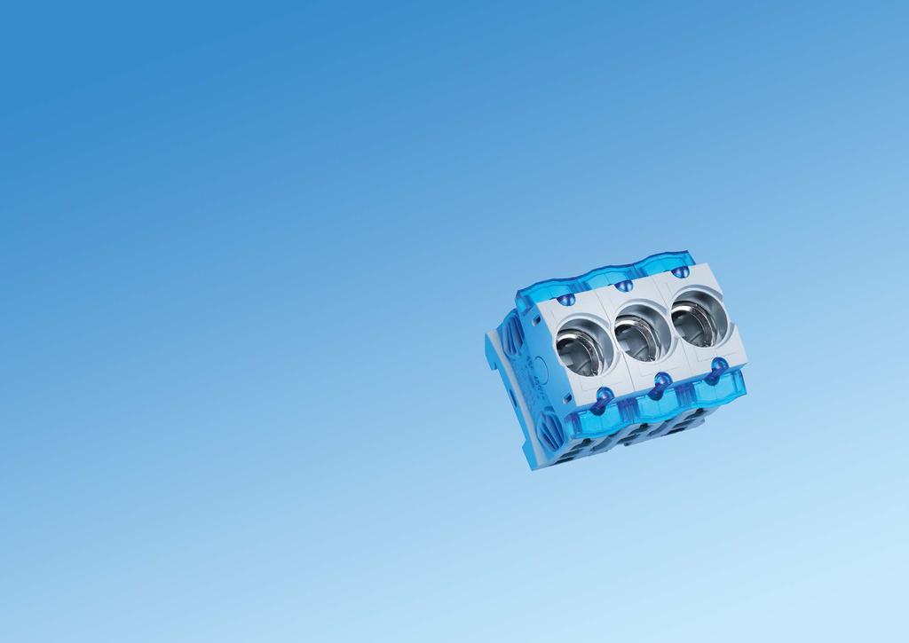
57 Panel 6


58 Panel devices for panel mounted and DIN rail 6 DEVICES FOR PANEL MOUNTED AND DIN RAIL Components for conventional mounting Panel For conventional wiring, Wöhner provides a comprehensive range of components for DIN rail or mounting plate assembly. The fuse technology and associated connection technology meet the high safety and quality requirements set by international standards. Thanks to their snap-action switch mechanisms, the switching devices offer high switching capacity and special protection via operator-independent switching. Selected products are ideal for special applications in the field of photovoltaics.


59 Panel devices for panel mounted and DIN rail 6 CUSTO Panel TRITON Panel AMBUS Panel AMBUS Panel UL version The CUSTO fuse-base D01 and D02 for installation in the 45 mm standard field cutout offer high security and favourable connection conditions. large terminal range up to 35 mm² dual-function terminal to 35 mm² + 16 mm² connection of all types of conductors integrated cover and comprehensive touch-safe protection The TRITON fuse-base D01, D02, DII and DIII in a particularly robust design with touch-safe protection in accordance with DGUV V3 for industrial applications. large terminal range up to 35 mm² dual-function incoming terminal connection of all types of conductors spring-loaded contact The holder for cylindrical fuses is available in 1-, 2- and 3-pole versions as well versions with a neutral conductor, LED, auxiliary switch and for semiconductor protection. 32 A (10x38), 50 A (14x51), 100 A (22x58) rated voltage to 690 V touch-safe protection to VDE 0106 photovoltaic versions to 1000 V DC are also UL listed Versions for Class CC to 30 A and Class J to 60 A fuses according to UL / -8. All products are provided with touch-safe protection and convenient connection technology. short-circuit capacity up to 200 ka rated voltage 600 V versions available with LED as fuse indicator SECUR Panel SECUR Panel QUADRON Panel QUADRON Panel Speed The SECUR fuse-holder especially for photovoltaic applications allows convenient fuse changes by means of a removable fuse carrier. Contacts in the carrier also feature touch-safe protection. for 10x85 (14x85) fuses up to 1500 V DC equipment width 22.5 mm UL listed The D0 fuse-switch-disconnector offers a high degree of safety and comfort for the operator. Fuse replacement is possible only when switched off. dual-function terminal to 35 mm² captive fuse carrier with commercial gauge ring optional auxiliary switch The NH fuse-switchdisconnectors for s 000 to 4a safeguard and disconnect currents up to 1600 A. NH 000 to 2 can also be mounted on DIN rails NH 00 to 3 versions with fuse monitoring various accessories for connection and shrouding One highlight is the QUADRON Panel switch-disconnector with NH fuses. Its snap-action switch mechanism ensures safe, operator-independent switching. double break lockable in OFF position FLAG indicator for switch position indication rotary drive versions or fuse monitoring CAPUS Panel CAPUS Panel MOTUS Panel Product series of small load switches. switch-disconnectors from 16 A A 3-pole and 4-pole versions optional door coupling rotary drives UL listed Product series of large load switches in three different versions. switch-disconnectors with NH fuse-link 160 A A switch-disconnectors from 125 A A changeover switch from 125 A A. also 3-pole + N versions The MOTUS hybrid motor starter can supply motors up to 4 kw. The integrated functions direct and reversing starter, overload protection and emergency switch-off lead to a significant reduction in space and wiring requirements. 3 design versions: 0.6 A, 2.4 A and 9 A equipment width 22.5 mm up to 30 mil. switching cycles UL listed

60 MOTUS Panel - Hybrid-motor starters for switching of inductive loads 6 1 CUSTO Panel - Panel mounted D0 fuse-bases version with touch-safe protection, dual-function terminal on both sides Panel devices for panel mounted and DIN rail 6 2 Hybrid motor starter, with reversing function and CrossLink Technology, 22.5 mm wide for mounting on mounting rails TH35 acc. to EN Width Height Depth A direct and reversing starter A direct and reversing starter A direct and reversing starter Accessories connecting plug with cable connection, 2 units connecting plug with cable connection, 3 units connecting plug with cable connection, 4 units Replacement component electronic unit A direct and reversing starter electronic unit A direct and reversing starter electronic unit A direct and reversing starter adapter for MOTUS Panel fuse 16 A for version 0.6 A and 2.4 A fuse 20 A for version 9 A fuse 30 A for version 9 A for motors with heavy-duty starting D0 fuse-base, version for distribution boards Rated voltage Poles Connection mm² E 14 / 16 A / 1P 400 V 1-pole E 14 / 16 A / 3P 3-pole E 18 / 63 A / 1P 1-pole E 18 / 63 A / 3P 3-pole Comb-type busbar, length 1 m Centre feed End feed Cross-section mm² comb-type busbar, 1-pole, bridge type, pitch 27 mm 130 A 80 A A 130 A comb-type busbar, 3-pole, bridge type, pitch 27 mm 130 A 80 A A 130 A Connection terminal, for comb-type busbars, bridge version Article Connection min. max. Rated current connection terminal, side connection 6-50 mm² for 31014, 125 A , 31309, connection terminal, side connection for 31012, connection terminal, front connection 31310, connection terminal, front connection for A connection terminal, front connection mm² for a connection terminal is required for each phase End cover, for comb-type busbars for 2-pole and 3-pole comb-type busbars 16 mm² for 3-pole comb-type busbars 35 mm² Accessories.1; 7.2
61 TRITON Panel - D0 panel mounted fuse-bases touch-safe protection in accordance with EN / DGUV V3 for industrial applications with dual-function terminal on incoming connection, box terminal on outgoing terminal 6 3 SECUR Panel - D0 switch-disconnector-fuses 63 A touch-safe protection in accordance with EN 50274/DGUV V5, dual-function terminal on both sides Panel devices for panel mounted and DIN rail 6 4 D0 fuse-base, industrial version, pitch 27 mm Rated voltage Poles Connection mm² E 14 / 16 A / 1P 400 V 1-pole E 14 / 16 A / 3P 400 V 3-pole E 18 / 63 A / 1P 400 V 1-pole E 18 / 63 A / 3P 400 V 3-pole Comb-type busbar, length 1 m Cross-section mm² Centre feed End feed comb type busbar, 1-pole, fork type, pitch 27 mm A 80 A comb type busbar, 3-pole, fork type, pitch 27 mm comb-type busbar, 1-pole, bridge type, pitch 27 mm comb-type busbar, 3-pole, bridge type, pitch 27 mm A 130 A End cover, for comb-type busbars for 2-pole and 3-pole comb-type busbars 16 mm² for 3-pole comb-type busbars 35 mm² Connection terminal, for comb-type busbars, bridge version Article Connection mm² connection terminal, side connection for 31014, 31024, 31309, connection terminal, side connection for 31012, 31310, connection terminal, front connection for 31012, 31310, Rated current A A A connection terminal, front connection for A a connection terminal is required for each phase Label holder for Triton, snap-on Label, for label holder clip 20 x D0 switch-disconnector-fuses Rated current Connection mm² 1-pole 63 A pole+N pole pole pole+N V AC / 130 V DC for 2-pole version D0 Switch-disconnector-fuses, with LED 1-pole 63 A pole V AC / 130 V DC for 2-pole version LED signals tripped fuse Reducer reducer D02 for D01 fuses 2-16 A Pilot switch, for monitoring the switch position, 9 mm wide 1 NO / 1 NC : 400 V AC / 2 A, 24 V DC / 6 A Comb-type busbar, length 1 m Cross-section mm² Centre feed End feed comb-type busbar, 1-pole, bridge type, pitch 27 mm A 80 A A 130 A comb-type busbar, 3-pole, bridge type, pitch 27 mm A 80 A A 130 A End cover, for comb-type busbars for 2-pole and 3-pole comb-type busbars 16 mm² for 3-pole comb-type busbars 35 mm² Connection terminal, for comb-type busbars, bridge version Article Connection mm² connection terminal, side connection for 31014, 31024, 31309, for 31012, 31310, connection terminal, front connection for 31012, 31310, a connection terminal is required for each phase Part No for for fuse links not included Accessories.1; 7.2 Accessories.1

62 TRITON Panel - D fuse-bases touch-safe protection in accordance with EN / DGUV V3 for industrial applications 6 5 AMBUS Panel - Fuse-holders for IEC cylindrical fuses type AES with box terminals, with touch-safe protection in accordance with EN Panel devices for panel mounted and DIN rail 6 6 D fuse-base, industrial version, for screw-in gauge rings Rated voltage Poles Connection mm² E 27 / 25 A / 1P, for screw-in gauge rings 500 V E 27 / 25 A / 3P, for screw-in gauge rings 500 V E 33 / 63 A / 1P, for screw-in gauge rings * 500 V E 33 / 63 A / 3P, for screw-in gauge rings * 500 V * acc. to VDE also for 690 V AC / 600 V DC Comb-type busbar, length 1 m Cross-section mm² Centre feed End feed 1-pole comb-type busbar, for E27, pitch 40 mm A 80 A pole comb-type busbar, for E27, pitch 40 mm pole comb type busbar, for E33, pitch 50 mm pole comb-type busbar, for E33, pitch 50 mm End cover, for comb-type busbars for 2-pole and 3-pole comb-type busbars 16 mm² Connection terminal, for comb-type busbars Article Connection mm² connection terminal, side connection for 31014, 31024, 31309, connection terminal, side connection for 31012, 31310, a connection terminal is required for each phase Rated current A connection terminal, front connection Label holder for Triton, snap-on Label, for label holder clip 20 x Fuse-holder for cylindrical fuses, standard version Rated current Poles Connection Width 10x38 32 A 1-pole mm² / AWG pole pole x51 50 A 1-pole mm² / AWG pole pole x A 1-pole 4-50 mm² / AWG 10-1/ pole pole Fuse-holder for cylindrical fuses, standard version with LED V AC / DC 10x38 32 A 1-pole mm² / AWG x38 2-pole x38 3-pole x51 50 A 1-pole mm² / AWG x51 3-pole x A 1-pole 4-50 mm² / AWG 10-1/ x58 3-pole LED signals tripped fuse Fuse-holder for cylindrical fuses, standard version with LED V AC / DC 10x38 32 A 1-pole mm² / AWG LED signals tripped fuse Fuse-holder for cylindrical fuses, standard version, neutral conductor on right 10x38 32 A 1-pole+N mm² / AWG x38 3-pole+N x51 50 A 1-pole+N mm² / AWG x51 3-pole+N x A 1-pole+N 4-50 mm² / AWG 10-1/ x58 3-pole+N Fuse-holder for cylindrical fuses, standard version, neutral conductor on left 14x51 50 A 3-pole+N mm² / AWG x A 3-pole+N 4-50 mm² / AWG 10-1/ Fuse-holder for cylindrical fuses, standard design, integrated neutral conductor (left) 10x38 32 A 1-pole+N mm² x38 3-pole+N mm² N-module 10x38 32 A N mm² / AWG Accessories.1 Accessories.7; 7.8

63 AMBUS Panel - Fuse-holders for IEC cylindrical fuses type AES with box terminals, with touch-safe protection in accordance with EN AMBUS Panel - Accessories for AES fuse-holder for cylindrical fuses Panel devices for panel mounted and DIN rail 6 8 Fuse-holder for cylindrical fuses, version for semiconductor protection fuses Rated current Poles Connection Width 10x38 32 A 1-pole mm² / AWG pole pole x51 50 A 1-pole mm² / AWG pole pole x A 1-pole 4-50 mm² / AWG 10-1/ pole pole Fuse-holder for cylindrical fuses, version for semiconductor protection fuses, with pilot switch 14x51 50 A 1-pole mm² / AWG x51 2-pole x51 3-pole x A 1-pole 4-50 mm² / AWG 10-1/ x58 2-pole x58 3-pole Pilot switch indicates when no fuse is inserted, holder is open, or fuse (with striker) is tripped Fuse holder for cylindrical fuses, photovoltaic version, 1000 V 10x38 / 1P 30 A 1-pole mm² / AWG x38 / 1P / LED * 1-pole x38 / 2P 2-pole * LED indicates blown fuse, operating range V Fuse-holder for cylindrical fuses, photovoltaic version, 1500 V 10x85 * 32 A 1-pole mm² / AWG * also suitable for 14 x 85 fuses Comb-type busbar, length 1 m Cross-section mm² Centre feed End feed comb-type busbar, 1-pole, bridge type, pitch 18 mm A 80 A comb-type busbar, 3-pole, bridge type, pitch 18 mm comb-type busbar, 1-pole, bridge type, pitch 27 mm comb-type busbar, 3-pole, bridge type, pitch 27 mm comb-type busbar, 1-pole, bridge type, pitch 18 mm A 100 A comb-type busbar, 2-pole, bridge type, pitch 18 mm comb-type busbar, 3-pole, bridge type, pitch 18 mm comb-type busbar, 1-pole, bridge type, pitch 27 mm A 130 A comb-type busbar, 3-pole, bridge type, pitch 27 mm End cover, for comb-type busbars for 2-pole and 3-pole comb-type busbars 16 mm² for 1-pole comb-type busbars 25 mm² for 2-pole and 3-pole comb-type busbars 25 mm² for 3-pole comb-type busbars 35 mm² Connection terminal, for comb-type busbars Article Connection mm² Rated current PG Part No. connection terminal, side connection for 31101, A connection terminal, front connection for 31101, for A for 31549, connection terminal, side connection for 31014, 31024, A , for 31012, 31310, connection terminal, front connection for 31012, 31310, for A for a connection terminal is required for each phase Connection set, for custom combinations of multipole units connection kit 10x38, 2-pole connection kit 10x38, 3-pole connection kit 14x51, 2-pole multipole devices can be produced with each set, depending on the version (2 or 3-pole) Spacer 4.5 mm, set for 50 fuse holders set for 50 fuse holders and Accessories.7; 7.8
64 6 9 Panel devices for panel mounted and DIN rail 6 10 AMBUS Panel - Fuse-holders for Class CC fuses type AES with box terminals, with touch-safe protection in accordance with EN 50274, for fuses that conform to UL AMBUS Panel - QUADRON Panel - Fuse-holders for Class J fuses with touch-safe protection, for fuses that comply with UL Class CC fuse-holder for cylindrical fuses, Class CC, standard version Poles Connection Width 30 A / 600 V 1-pole mm² / AWG A / 600 V 2-pole A / 600 V 3-pole Class CC fuse-holder for cylindrical fuses, Class CC, standard version with LED V AC / DC 30 A / 600 V 1-pole mm² / AWG A / 600 V 2-pole A / 600 V 3-pole LED signals tripped fuse Class CC fuse-holder for cylindrical fuses, Class CC, standard version with LED V AC / DC 30 A / V 1-pole mm² / AWG LED signals tripped fuse Comb-type busbar, length 1 m Class J fuse-holder, AMBUS Panel, DIN rail mounted, standard version Poles Connection Width 30 A / 600 V (21x57) 1-pole mm² / AWG pole pole A / 600 V (27x60) 1-pole mm² / AWG pole pole Class J fuse-holder, AMBUS Panel, DIN rail mounted, standard version with LED V AC / DC 30 A / 600 V (21x57) 1-pole mm² / AWG A / 600 V (21x57) 2-pole A / 600 V (21x57) 3-pole A / 600 V (27x60) 1-pole mm² / AWG A / 600 V (27x60) 2-pole A / 600 V (27x60) 3-pole LED signals tripped fuse Cross-section mm² Centre feed End feed comb-type busbar, 1-pole, bridge type, pitch 18 mm A 100 A comb-type busbar, 2-pole, bridge type, pitch 18 mm comb-type busbar, 3-pole, bridge type, pitch 18 mm Connection terminal, for comb-type busbars Connection mm² for for 31549, Class J fuse-holder, QUADRON Panel, for screwing onto mounting plate 100 A / 600 V (29 x 118) * 3-pole 4-50 mm² / AWG 14-2/ A / 600 V (41x146) * mm² / AWG MCM A / 600 V (54x181) mm² / AWG 4 - MCM * do not use fuse links with sharp-edged blades a connection terminal is required for each phase End cover, for comb-type busbars for 1-pole comb-type busbars 25 mm² for 2-pole and 3-pole comb-type busbars 25 mm² Accessories.9 Accessories.10; 7.11

65 QUADRON Panel - Fuse-bases for NH fuses for standard and long version (PV) 6 11 QUADRON Panel - Accessories for NH fuse-bases Panel devices for panel mounted and DIN rail 6 12 NH fuse-base for photovoltaic, 1-pole, with touch-safe protection, screw on both sides, 1000 V AC / 1500 V DC Rated current Rated voltage Size both sides screw M A NH 1XL both sides screw M12 * 600 A NH 2XL / 3L * for fuse-link NH 2XL or NH 3L in accordance with IEC with max. 100 W power dissipation NH fuse-base for photovoltaic, 1-pole, with touch-safe protection, 1000 V AC / 1500 V DC incoming connection screw M10, outgoing connection 250 A 1500 V NH 1XL to busbar 2x 30 x 10 incoming connection screw M10, outgoing connection 250 A 1500 V NH 1XL to busbar 2x 30 x 10, for integrated mounting of CTs type LEM HTA incoming connection screw M10, outgoing connection to busbar 2x 40 x 10 * 600 A 1500 V NH 2XL / 3L * for fuse-link NH 2XL or NH 3L in accordance with IEC with max. 100 W power dissipation; information on rated load factors with regard to current carrying capacity is available on request or at Accessories grip lug cover * * 2 pieces required per fuse NH fuse-base, 00, barrier version Rated current Size Number of poles Connection mm² both sides screw M8, without barrier 160 A NH both sides screw, with 2 barriers both sides terminal, without barrier both sides clamp, with 2 barriers Grip lug cover, ts bas s it tou saf rot tion Size for NH base and * for NH fuse-base ** * 1 piece required per fuse ** 2 pieces required per fuse Barrier and barrier support Article barrier for 03350, 03351, 03354, barrier support, for lateral barrier for 03350, 03351, 03354, Neutral conductor, screw-on mounting Rated current Connection mm² 160 A clamp, both sides A screw M8 at both sides Neutral conductor, disconnectable, screws-on or clip-on onto mounting rail TH 35 EN A Neutral conductor, disconnectable, screw-on mounting Rated current Length Connection mm² 160 A clamp on both sides A screw M8 at both sides A screw M10 at both sides A screw M12 at both sides NH fuse-base, , version with touch-safe protection both sides screw M8 160 A NH both sides clamp both sides screw M A NH both sides clamp both sides screw M A NH both sides screw M A NH Connecting terminal 160 A 60 mm long, both sides clamp 160 A 125 mm long, both sides clamp 250 A 100 mm long, both sides screw M A 200 mm long, both sides screw M A 100 mm long, both sides screw M A 200 mm long, both sides screw M12 possible combinations: 3-pole NH bases with neutral conductor (neutral conductor attachable to NH base) (clamp on both sides) (M8 screw on both sides) ot r ombinations ossib if t n utra on u tors ar tt s arat Accessories.5; 7.6


66 QUADRON Panel - NH fuse-switch-disconnectors 000-4a type LTS and QCB for panel mounted 6 13 QUADRON Panel - Accessories NH fuse-switch-disconnector, Panel devices for panel mounted and DIN rail 6 14 NH fuse-switch-disconnector, 000-3, 3-pole Rated current Size box terminal 125 A NH clamp 70 mm² 160 A NH screw M box terminal 250 A NH screw M screw M A NH screw M A NH NH fuse-switch-disconnector, 4a, 3-pole 2x screw M A NH 4a NH fuse-switch-disconnector, 00, 3-pole, with short touch-safe protection clamp 70 mm², with short protection cover 160 A NH screw M8, with short protection cover NH fuse-switch-disconnector, 00-3, 3-pole, with electronic fuse monitoring clamp 70 mm² 160 A NH screw M screw M A NH screw M A NH screw M A NH circuit diagram for fuse monitoring is available at NH fuse-switch-disconnector, 00-3, 3-pole, with electromechanical fuse monitoring clamp 70 mm² 160 A NH screw M screw M A NH screw M A NH screw M A NH circuit diagram for fuse monitoring is available at Comb-type busbar, closed version with end covers Cross-section mm² Usable with comb-type busbar, 3-pole, for 2 NH fuse switch disconnectors comb-type busbar, 3-pole, for 2 NH fuse switch disconnectors comb-type busbar, 3-pole, for 3 NH fuse switch disconnectors comb-type busbar, 3-pole, for 4 NH fuse switch disconnectors Connection terminal, for comb-type busbars Connection mm² for 3-pole comb-type busbar 35 mm², suitable for NH-fuse-switch-disconnector 000 with box terminal for 3-pole comb-type busbar 35 mm², suitable for NH-fuse-switch-disconnector 00 with screw connection Connection accessories Connection Size box terminal for Cu cables mm² / 24 x clamp connector mm² / 12 x clamp connector for Cu cables mm² / 18 x clamp connector for Cu cables mm² / 21 x clamp connector for Cu cables mm² / 25 x M8 screw connector prism terminal, single, for Cu and Al cables * mm² prism terminal, single, for Cu and Al cables * mm² prism terminal, single, for Cu and Al cables * mm² prism terminal, single, for Cu and Al cables * mm² prism terminal, double, for Cu cables 2x mm² prism terminal, double, for Cu cables 2x mm² prism terminal, double, for Cu cables 2x 150 mm² prism terminal, double, for Cu cables 2x 185 mm² tunnel terminal for screw connection M8 1x mm² + 2x mm² * when using aluminium conductors, observe the maintenance instructions (see 8.2) Accessories ; 7.5-6

67 QUADRON Panel - Accessories NH fuse-switch-disconnectors, QUADRON Panel - Accessories NH fuse-switch-disconnectors, Panel devices for panel mounted and DIN rail 6 16 Cover, for cable lugs, attachable at the top and bottom Size for 33200, 33208, 33329, 33394, 33398, for 33221, for QCB-NH1 and QCS 320 A for QCB-NH for QCB-NH Cover, for connection area, attachable at the top and bottom for NH fuse-switch-disconnector for NH fuse-switch-disconnector 3, max. 600 A Barrier for handle for closing of handle area from rear Trim frame, cover with front plate assembly W x L Size trim frame, single 130 x 210 x trim frame, double 199 x 166 x trim frame, single 130 x 210 x trim frame, double 232 x 210 x trim frame, triple 340 x 210 x trim frame, single * 143 x 210 x trim frame, double * 250 x 210 x trim frame, single 215 x 330 x trim frame, single 248 x 330 x trim frame, single 290 x 330 x * for 33221, Pilot switch, for monitoring the disconnector lid position Size changeover 250 V AC / 5 A, 30 V DC / 4 A changeover 250 V AC / 5 A, 30V DC / 4 A not usable for fuse switch disconnectors 1 Disconnector lid interlock for sealing wire for sealing wire for sealing wire or 3 padlocks with shackle of 4-7 mm Rapid mounting set, for rails in accordance with EN (TH 35 x 7.5 mm) for 1 mouinting rail for 2 mounting rails, rails centre distance 125 mm or 150 mm for 2 mounting rails, rails centre distance 125 mm or 150 mm Arc chamber r tro t a ag for ig r uti isation at gor

68 QUADRON Panel - Switch-disconnectors 160 A A and 00-1 type QCS, with snap-action switch mechanism 6 17 CAPUS Panel - Switch-disconnectors 3-pole 16 A A type SD1, SD2, SD3 Panel devices for panel mounted and DIN rail 6 18 Switch-disconnector, 3-pole switchable, with snap-action switch mechanism, with multifunction handle Rated current Width box terminal * 160 A screw M10 * 320 A * as main s it or m rg n o s it on it t fo o ing maximum o rating urr nt 160 A version: 125 A / 690 V AC; 320 A version: 280 A / 400 V AC, 250 A / 690 V AC Switch-disconnector, 3-pole switchable, with snap-action switch mechanism, with door coupling rotary drive box terminal, for door coupling twist handle * 160 A screw M10, for door coupling rotary handle * 320 A additional extension shaft and door coupling rotary handle required * as main s it or m rg n o s it on it t fo o ing maximum o rating urr nt 160 A version: 125 A / 690 V AC; 320 A version: 280 A / 400 V AC, 250 A / 690 V AC NH switch-disconnector-fuses, 3-pole switchable, with snap-action switch mechanism, with multifunction handle Rated current Size Width box terminal 125 A NH box terminal, with electronic fuse monitoring 125 A NH screw M A NH fuse monitoring on request fuses are not included in the scope of delivery NH switch-disconnector-fuses, 3-pole switchable, with snap-action switch mechanism, with door coupling rotary drive box terminal, for door coupling rotary handle 125 A NH screw M10, for door coupling rotary handle 250 A NH additional extension shaft and door coupling rotary handle required fuses are not included in the scope of delivery Accessories Usable for version Connection mm² connection for auxiliary line, for box terminal QCB-NH00, QCS-NH00, QCS 160 A 6.3 x connecting terminal 120 mm² QCS-NH00, QCS 160 A box terminal for Cu cables QCB-NH1, QCS-NH1, QCS 320 A mm² / 24 x prism terminal, single, for Cu and Al cables * mm² prism terminal, double, for Cu cables 2x mm² cover for cable lugs, top / bottom attachable pilot switch for monitoring the switch position QCS-NH00 / 1, QCS door coupling rotary handle, black, without shaft ** 160 A / 320 A door coupling rotary handle, red-yellow, without shaft ** extension shaft, 290 mm long extension shaft, 490 mm long for current capacity of the terminals visit * when using aluminium conductors, observe the maintenance instructions (see 8.2) ** switch can also be installed 90 left / right, always with the same handle position Switch-disconnectors, 3-pole, with rotary handle graphite-grey Article Rated current Dimensions box terminal mm², graphite grey handle box terminal mm², graphite grey handle box terminal mm², graphite grey handle box terminal mm², graphite grey handle box terminal mm², graphite grey handle box terminal mm², graphite grey handle box terminal mm², graphite grey handle box terminal mm², graphite grey handle box terminal mm², graphite grey handle box terminal mm², graphite grey handle SD A 36 x 81 x SD A 36 x 81 x SD A 36 x 81 x SD A 36 x 81 x SD A 36 x 81 x SD A 52 x 100 x SD A 52 x 100 x SD A 52 x 100 x SD A 65 x 113 x SD A 65 x 113 x Switch-disconnectors, 3-pole, with rotary handle red-yellow box terminal mm², yellow-red handle SD A 36 x 81 x box terminal mm², yellow-red handle SD A 36 x 81 x box terminal mm², yellow-red handle SD A 36 x 81 x box terminal mm², yellow-red handle SD A 36 x 81 x box terminal mm², yellow-red handle SD A 36 x 81 x box terminal mm², yellow-red handle SD A 52 x 100 x box terminal mm², yellow-red handle SD A 52 x 100 x box terminal mm², yellow-red handle SD A 52 x 100 x box terminal mm², yellow-red handle SD A 65 x 113 x box terminal mm², yellow-red handle SD A 65 x 113 x fuse links not included Accessories.5; 7.6 New product Accessories 6.20


69 CAPUS Panel - Switch-disconnectors 3-pole + N, 16 A A type SD1, SD2, SD CAPUS Panel - Handles and accessories Panel devices for panel mounted and DIN rail 6 20 Switch-disconnectors, 3-pole + N, with rotary handle graphite-grey Article Rated current Dimensions box terminal mm², graphite grey handle box terminal mm², graphite grey handle box terminal mm², graphite grey handle box terminal mm², graphite grey handle box terminal mm², graphite grey handle box terminal mm², graphite grey handle box terminal mm², graphite grey handle box terminal mm², graphite grey handle box terminal mm², graphite grey handle box terminal mm², graphite grey handle SD A 51 x 81 x SD A 51 x 81 x SD A 51 x 81 x SD A 51 x 81 x SD A 51 x 81 x SD A 69 x 100 x SD A 69 x 100 x SD A 69 x 100 x SD A 87 x 113 x SD A 87 x 113 x Rotary handle Article rotary handle for door coupling drive, black, without shaft rotary handle for door coupling drive, yellow-red, without shaft rotary handle for door coupling drive, black, without shaft, with defeater rotary handle for door coupling drive, yellow-red, without shaft, with defeater SD1-3, SD1-4, SD2-3, SD SD1-3, SD1-4, SD2-3, SD2-4, SD3-3, SD SD1-3, SD1-4, SD2-3, SD2-4, SD3-3, SD SD1-3, SD1-4, SD2-3, SD2-4, SD3-3, SD Extension shaft extension shaft, 100 mm long SD1-3, SD1-4, SD2-3, SD2-4, SD3-3, SD extension shaft, 200 mm long SD1-3, SD1-4, SD2-3, SD2-4, SD3-3, SD extension shaft, 300 mm long SD1-3, SD1-4, SD2-3, SD2-4, SD3-3, SD Switch-disconnectors, 3-pole + N, with rotary handle red-yellow box terminal mm², yellow-red handle SD A 51 x 81 x box terminal mm², yellow-red handle SD A 51 x 81 x box terminal mm², yellow-red handle SD A 51 x 81 x box terminal mm², yellow-red handle SD A 51 x 81 x box terminal mm², yellow-red handle SD A 51 x 81 x box terminal mm², yellow-red handle SD A 69 x 100 x box terminal mm², yellow-red handle SD A 69 x 100 x box terminal mm², yellow-red handle SD A 69 x 100 x box terminal mm², yellow-red handle SD A 87 x 113 x box terminal mm², yellow-red handle SD A 87 x 113 x Pilot switch, for monitoring the switch setting 1 n/c + 1 n/o, screw terminal SD1-3, SD1-4, SD2-3, SD2-4, SD3-3, SD Terminal space cover connection space cover SD connection space cover SD connection space cover SD connection space cover SD connection space cover SD connection space cover SD New product Accessories 6.20 New product

70 CAPUS Panel - NH switch-disconnectors-fuses 00-3 type LTS-F 6 21 CAPUS Panel - Switch-disconnectors 250 A A type LTS Panel devices for panel mounted and DIN rail 6 22 NH switch-disconnector-fuses, 3-pole, 690 V AC, with rotary handle Rated current Size screw M8, graphite grey handle 160 A NH screw M10, graphite grey handle 250 A NH screw M10, graphite grey handle 400 A NH screw M12, graphite grey handle 630 A NH screw M8, red handle 160 A NH screw M10, red handle 250 A NH screw M10, red handle 400 A NH screw M12, red handle 630 A NH fuses and terminal compartment covers are not included in the scope of delivery Terminal space cover, attachable at top and bottom Usable with for covering all connections, dark grey LTS-250, LTS-F LTS-400/630, LTS-F 250/ LTS-800, LTS-F Pilot switch, for monitoring the switch setting 1 n/c + 1 n/o, plug connectors 6.3 x 0.8 LTS, LTS-F Door coupling drive, without rotary handle door coupling rotary drive, graphit-grey blind cover LTS-250/400/630 LTS-F 160/250/ door coupling rotary drive, graphite-grey blind cover, for closing with padlocks and door inter-locking door coupling rotary drive, red-yellow blind cover, for closing with padlocks and door inter-locking LTS-250/400/630, LTS-F160/250/ LTS-800, LTS-F LTS-250/400/630, LTS-F 160/250/ LTS-800, LTS-F extension shaft, 300 mm long LTS-250/400/630, LTS-F 160/250/ LTS-800, LTS-F extension shaft, 550 mm long LTS-250/400/630, LTS-F 160/250/ LTS-800, LTS-F Connection accessories Usable with Connection clamp connector for Cu conductors LTS-F mm² / 12 x 10 clamp connector for Cu cables clamp connector for Cu cables clamp connector for Cu cables QCB-NH1, QCS-NH1, LTS-F 250, LTS 400 QCB-NH2, LTS-F 400, LTS 630 QCB-NH3, LTS-F 630, LTS mm² / 18 x mm² / 21 x mm² / 25 x wedge clamp terminal, single, for Cu and Al cond. LTS-F 250, LTS mm² wedge clamp terminal, single, for Cu and Al cond. LTS-F 400, LTS mm² when using aluminium conductors, observe the maintenance instructions (see 8.2) Switch-disconnector, 3-pole, 500 V AC, with rotary handle Rated current screw M10, graphite grey handle 250 A A A screw M12, graphite grey handle 800 A screw M10, red handle 250 A A A screw M12, red handle 800 A fuses and terminal compartment covers are not included in the scope of delivery. Terminal space cover, attachable at top / bottom Usable with for covering all connections, dark grey LTS-250, LTS-F LTS-400/630, LTS-F 250/ LTS-800, LTS-F Pilot switch, for monitoring the switch setting 1 n/c + 1 n/o, plug connectors 6.3 x 0.8 LTS, LTS-F Door coupling drive, without rotary handle door coupling rotary drive, graphit-grey blind cover LTS-250/400/630 LTS-F 160/250/ door coupling rotary drive, graphite-grey blind cover, for closing with padlocks and door inter-locking door coupling rotary drive, red-yellow blind cover, for closing with padlocks and door inter-locking LTS-250/400/630, LTS-F160/250/ LTS-800, LTS-F LTS-250/400/630, LTS-F 160/250/ LTS-800, LTS-F extension shaft, 300 mm long LTS-250/400/630, LTS-F 160/250/ LTS-800, LTS-F extension shaft, 550 mm long LTS-250/400/630, LTS-F 160/250/ LTS-800, LTS-F Connection accessories Usable with Connection mm² clamp connector for lam. Cu LTS x clamp connector for Cu cables QCB-NH1, QCS-NH1, LTS-F 18 x , LTS 400 clamp connector for Cu cables QCB-NH2, LTS-F 400, LTS 21 x clamp connector for Cu cables QCB-NH3, LTS-F 630, LTS 25 x wedge clamp terminal, single, for Cu and Al cond. * LTS wedge clamp terminal, single, for Cu and Al cond. * LTS-F 250, LTS wedge clamp terminal, single, for Cu and Al cond. * LTS-F 400, LTS * when using aluminium conductors, observe the maintenance instructions (see 8.2) fuse links not included Accessories.5; 7.6


71 CAPUS Panel - Switch-disconnectors 125 A A type LTS-T 6 23 CAPUS Panel - Handles and accessories for switch-disconnector type LTS-T Panel devices for panel mounted and DIN rail 6 24 Switch-disconnector, 3-pole, without rotary handle, without shaft Rated current box terminal 95 mm² 125 A screw M8 125 A box terminal 95 mm² 160 A screw M8 160 A screw M A screw M A screw M A screw M A screw M A screw M A screw M14 * 1250 A screw M A screw M A screw M A screw M A screw M A rated current at 400 V AC * delivery time on request Switch-disconnector, 3-pole + N, without rotary handle, without shaft Rated current box terminal 95 mm² 125 A screw M8 125 A box terminal 95 mm² 160 A screw M8 160 A screw M A screw M A screw M A screw M A screw M A screw M A screw M14 * 1250 A screw M A screw M A screw M A screw M A * delivery time on request Rotary handle Usable with rotary handle for door coupling drive, graphite grey, LTS-T 125,160,200, with shaft door coupling rotary handle, graphite grey, with shaft LTS-T 315, LTS-T 630, LTS-T LTS-T 1600,1800,2000,2500, door coupling rotary handle, yellow-red, with shaft LTS-T 125,160,200, LTS-T 315, LTS-T 630, LTS-T LTS-T 1600,1800,2000,2500, direct rotary handle, graphite grey, with shaft LTS-T 125,160,200, LTS-T 315, LTS-T 630, LTS-T LTS-T 1600,1800,2000,2500, Terminal cover for covering all terminals at one side of the switch, transparent Terminal space cover for covering all terminals at one side of the switch, transparent LTS-T LTS-T 630, LTS-T LTS-T 1600, LTS-T 125,160,200, LTS-T 315, LTS-T 630, Pilot switch, for monitoring of the switch position 1 n/c + 1 n/o, plug connectors 6.3 x 0.8 LTS-T, LTSU-T n/c + 2 n/o, plug connectors 6.3 x Rapid mounting set rapid mounting set for 1 mounting rail TH 35 LTS-T 125, Accessories 6.21; 6.23
72 CAPUS Panel - Changeover switches 125 A A type LTSU-T 6 25 Accessories for switch-disconnector LTS-T and changeover switch LTSU-T Panel devices for panel mounted and DIN rail 6 26 Changeover switch, 3-pole, without rotary handle, without shaft Rated current screw M8 * 125 A screw M8 * 160 A screw M10 * 200 A screw M A screw M A screw M A screw M A screw M A screw M A rated current at 400 V AC * bridge cable required; 6 or 8 connections available Extension shaft Usable with extension shaft, 250 mm long LTS-T , LTSU-T extension shaft, 376 mm long LTS-T 315/400, LTSU-T extension shaft, 345 mm long LTS-T 630/ extension shaft, 336 mm long LTS-T 1250, LTSU-T extension shaft, 485 mm long LTS-T 1600/ extension shaft, 387 mm long LTS-T , LTSU-T extension shaft, 536 mm long LTS-T 315/ extension shaft, 525 mm long LTS-T 630/ extension shaft, 635 mm long LTS-T 1600/ Changeover switch, 3-pole + N, without rotary handle, without shaft screw M8 * 125 A screw M8 * 160 A screw M10 * 200 A screw M A screw M A screw M A screw M A screw M A screw M A rated current at 400 V AC * bridge cable required; 6 or 8 connections available Rotary handle door coupling rotary handle, graphite grey, with shaft LTSU-T 125,160, LTSU-T 250, LTSU-T 630, LTSU-T direct rotary handle, graphite grey, with shaft LTSU-T 125,160, LTSU-T 250, LTSU-T 630, LTSU-T Terminal cover terminal cover, transparent, 3-pole, for incoming II LTSU-T terminal cover, transparent, 3-pole, for incoming I terminal cover, transparent, 3-pole, for outgoing terminal cover, transparent, 4-pole, for incoming I and II LTSU-T terminal cover, transparent, 4-pole, for outgoing Pilot switch 1 n/c + 1 n/o, plug connectors 6.3 x 0.8 LTS-T, LTSU-T n/c + 2 n/o, plug connectors 6.3 x Accessories 6.26
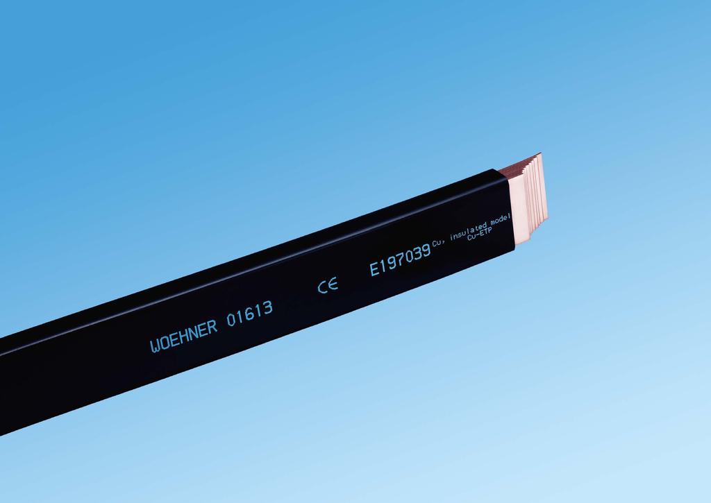
73 Accessories 7

74 D0 fuses in accordance with IEC / HD / DIN VDE D0 fuses in accordance with IEC / HD / DIN VDE Accessories 7 2 Fuse-link gg (gl) Size Rated voltage Rated breaking capacity D01 fuse link 2 A 400 V AC / 250 V DC 50 ka AC / 8 ka DC D01 fuse link 4 A D01 fuse link 6 A D01 fuse link 10 A D01 fuse link 16 A D02 fuse link 20 A D02 fuse link 32 A D02 fuse link 25 A D02 fuse link 40 A D02 fuse link 35 A D02 fuse link 50 A D02 fuse link 63 A Ferrule gauge ring for E 14 D01 gauge ring 2 A D01 gauge ring 4 A D01 gauge ring 6 A D01 gauge ring 10 A Ferrule gauge ring for E 18 special D01 gauge ring 2 A special D01 gauge ring 4 A special D01 gauge ring 6 A special D01 gauge ring 10 A special D01 gauge ring 16 A D02 gauge ring 20 A D02 gauge ring 25 A D02 gauge ring 32 A D02 gauge ring 35 A / 40 A D02 gauge ring 50 A Screw cap, 400 V AC / 250 V DC Size D01 screw cap, porcelain E D01 screw cap, plastic D02 screw cap, porcelain E D02 screw cap, plastic D02 screw cap, plastic, with reducer for D Retaining cap locking cap D01 version "industry" E locking cap D01 version "utility" locking cap D02 version "industry" E locking cap D02 version "utility" Special retaining spring Size Rated current special-retaining spring for D01 - E A Gauge ring tool D01 - D Special key for retaining cap "industry" version D and D New product


75 D fuses in accordance with IEC / HD / DIN VDE D fuses in accordance with IEC / HD / DIN VDE Accessories 7 4 Fuse-link gg (gl) Size Rated voltage Rated breaking capacity D-fuse link 2 A 500 V AC / 500 V DC 50 ka AC / 8 ka DC E D-fuse link 4 A D-fuse link 6 A D-fuse link 10 A D-fuse link 16 A D-fuse link 20 A D-fuse link 25 A D-fuse link 35 A E D-fuse link 50 A D-fuse link 63 A Screw-in gauge ring screw-in gauge ring 2 A E 27 / E screw-in gauge ring 4 A screw-in gauge ring 6 A screw-in gauge ring 10 A screw-in gauge ring 16 A screw-in gauge ring 20 A screw-in gauge ring 25 A screw-in gauge ring 35 A E screw-in gauge ring 50 A screw-in gauge ring 63 A Screw cap Size Rated voltage D-screw cap, porcelain E V D-screw cap, plastic D-screw cap, porcelain E D-screw cap, plastic Retaining cap locking cap DII version "industry" E V locking cap DII version "utility" locking cap DIII version "industry" E locking cap DIII version "utility" Gauge screw key E 27 / E Gauge screw key E 27 / E Special key for retaining cap "industry" version D and D Gauge ring gauge ring 2 A E gauge ring 4 A gauge ring 6 A gauge ring 10 A gauge ring 16 A gauge ring 20 A gauge ring 25 A gauge ring 35 A E gauge ring 50 A gauge ring 63 A

76 NH fuses in accordance with IEC / HD / DIN VDE NH fuses in accordance with IEC / HD / DIN VDE Accessories 7 6 Fuse-link gg (gl) Size Rated current Rated voltage, AC Rated voltage, DC NH A 400 V 250 V A 500 V A A A A A A A A A A A NH A 440 V A A 690 V 250 V A A A A A A A A A A A NH fuses in accordance with 000 can be used in NH fuse bases, fuse-switch disconnectors and NH fuse-switch units of 00 Knife link Size Rated current NH A NH A NH A NH A NH 4a 1600 A Fuse-link gg Size Rated voltage, AC Rated voltage, DC Rated current NH V 440 V 20 A A A A A A A A A A V 250 V 160 A A A NH V 440 V 100 A A A A A A A V 355 A A V 250 A A NH V 315 A A A A V 400 A A NH 4a 500 V 440 V 800 A A A NH universal slip-on handle Size without sleeve New product
 Size Rated current Rated voltage Rated breaking capacity Power dissipation 10x38 1 A 500 V 120 ka 0.5 W 10 0.6 22 31008 2 A 0.7 W 10 0.6 22 31182 4 A 0.8 W 10 0.6 22 31183 6 A 0.9 W 10 0.")
77 Cylindrical fuses gg in accordance with IEC / HD Cylindrical fuses gr and gpv gr in accordance with IEC / EN and gpv in accordance with IEC / EN Accessories 7 8 Fuse-link gg (gl) Size Rated current Rated voltage Rated breaking capacity Power dissipation 10x38 1 A 500 V 120 ka 0.5 W A 0.7 W A 0.8 W A 0.9 W A 0.9 W A 1.3 W A 1.3 W A 1.9 W A 2.3 W A 2.8 W A 400 V 3.0 W x51 2 A 690 V 80 ka 0.8 W A 1.0 W A 120 ka 1.8 W A 80 ka 2.5 W A 3.0 W A 3.5 W A 500 V 3.8 W A 4.4 W A 400 V 120 ka 4.7 W x58 32 A 690 V 80 ka 4.3 W A 5.1 W A 5.5 W A 6.7 W A 500 V 120 ka 8.0 W A 9.0 W A 400 V 12.5 W Fuse-link gg (gl), with striker 14x51 6 A 500 V 80 ka 1.1 W x51 10 A 1.3 W x51 16 A 2.0 W x51 20 A 2.5 W x51 25 A 3.3 W x51 32 A 120 ka 3.5 W x51 40 A 4.8 W x58 50 A 690 V 80 ka 5.2 W x58 63 A 500 V 6.9 W x58 80 A 7.8 W Fuse-link gr Size Rated current Rated voltage Rated breaking capacity Power dissipation 10x38 1 A 690 V 200 ka 0.9 W A 1.0 W A 1.1 W A 1.6 W A 2.1 W A 3.1 W A 4.4 W A 5.8 W A 6.8 W A 8.2 W x51 10 A 2.6 W A 4.7 W A 6.0 W A 9.5 W A 10.0 W A 12.0 W x W A 16.0 W A 18.0 W A 19.0 W Fuse-link gpv, for photovoltaic applications 10x38 8 A 1000 V 30 ka 1.6 W A 2.0 W A 2.4 W A 2.1 W A 2.5 W x85 16 A 1100 V 3.8 W A 4.7 W A 5.9 W
78 Cylindrical fuses Class CC in accordance with UL Cylindrical fuses Class J in accordance with UL Accessories 7 10 Fuse-link, Class CC, time delay Size Rated current Rated voltage Rated breaking capacity Class CC 0.5 A 600 V 200 ka A A A A A A A A A A A A A A A Fuse-link, Class CC, fast acting Class CC 0.5 A 600 V 200 ka A A A A A A A A A A A A A Fuse-link, Class J, time delay Size Rated current Rated voltage Rated breaking capacity Class J, 21x57 1 A 600 V 200 ka A A A A A A A A A A A Class J, 27x60 35 A A A A A Class J, 29x A A A A Class J, 41x A A A A Class J, 54x A A A A

79 Cylindrical fuses Class J in accordance with UL Insulators Accessories 7 12 Fuse-link, Class J, fast acting Size Rated current Rated voltage Rated breaking capacity Class J, 21x57 10 A 600 V 200 ka A A A A Class J, 27x60 35 A A A A Class J, 29x A A A Class J, 41x A A A A Class J, 54x A A A A Insulator, with female thread Total height Female thread, both sides i t a ross flats Rated voltage 20 M V M V M V M V M V M V M V M V M V M V M V M V M V M V Insulator, with threaded bolt and female thread 30 M V M V M V

80 Laminated copper busbars 7 13 Laminated copper busbars Accessories 7 14 Laminated copper busbar, plain, insulated (105 C), length 2 m Dimensions (number of laminates x width x thickness) Cross-section mm² Rated current 30 K Rated current 50 K 3 x 9 x A 162 A x 9 x A 240 A x 15.5 x A 279 A x 15.5 x A 350 A x 15.5 x A 470 A x 20 x A 326 A x 20 x A 477 A x 20 x A 640 A x 24 x A 438 A x 24 x A 494 A x 24 x A 547 A x 24 x A 641 A x 24 x A 727 A x 32 x A 617 A x 32 x A 894 A x 40 x A 736 A x 40 x A 809 A x 40 x A 1053 A x 50 x A 880 A x 50 x A 1114 A x 50 x A 1244 A x 63 x A 1061 A x 63 x A 1481 A x 80 x A 1777 A x 100 x A 2110 A the pure copper weight is given, this does not include the weight of the insulation. Laminated copper busbar, tin-plated, insulated (105 C), length 2 m Dimensions (number of laminates x width x thickness) Cross-section mm² Rated current 30 K Rated current 50 K 4 x 15.5 x A 279 A x 15.5 x A 350 A x 15.5 x A 470 A x 20 x A 477 A x 20 x A 640 A x 24 x A 494 A x 24 x A 727 A x 32 x A 617 A x 32 x A 894 A x 40 x A 736 A x 40 x A 1053 A x 50 x A 880 A x 50 x A 1244 A x 63 x A 1481 A the pure copper weight is given, this does not include the weight of the insulation. Holder for laminated busbars for 1x lam. Cu of 6 x 15.5 x 0.8 to 10 x 63 x for multiple fastening for lam. Cu of 5 x 40 x 1 to 10 x 100 x for mounting on standard C-rail Holder for laminated busbars for 1x lam. Cu of 6 x 15.5 x 0.8 to 10 x 63 x for multiple fastening for lam. Cu of 5 x 40 x 1 to 10 x 100 x for mounting on standard C-rail


81 Connection bars for PE or N 7 15 Connection and connecting terminals Accessories 7 16 PE and N busbar, current capacity 63 A, with self-locking screws Connection mm² Number of contact positions Dimensions L x W x D 10 8 terminal points 52 x 9 x terminal points 78 x 9 x terminal points 104 x 9 x terminal points 156 x 9 x terminal points 1000 x 9 x Connection terminal 35 suitable for PE and N busbars PE and N busbar, with terminal clamp, current capacity 63 A, with self-locking screws Connection Dimensions L x W x H without terminal clamp 6 terminal points 10mm², screw-on, 61.5 mm long 1 terminal clamp 25 mm² 12 terminal points 10mm², screw-on, mm long 2 terminal clamps 25 mm² 18 terminal points 10mm², screw-on, mm long 3 terminal clamps 25 mm² 24 terminal points 10mm², screw-on, mm long 4 terminal clamps 25 mm² 30 terminal points 10mm², screw-on, mm long 5 terminal clamps 25 mm² 36 terminal points 10mm², screw-on, mm long 15 terminal clamps 25 mm² 96 terminal points 10mm², screw-on, 1000 mm long for 10 mm² incoming connection the connection clamp must be reversed x 9 x x 9 x x 9 x x 9 x x 9 x x 9 x x 9 x Insulated PE and N terminal Rated current Connection mm² 63 A * 7x 10 mm² PE-terminal, green/yellow A * neutral terminal, blue A ** PE-terminal, green/yellow A ** neutral terminal, blue * for mounting on flat busbars 12 x 2 mm ** for clip-on mounting Connecting terminal 160 A mm long, both sides clamp mm long, both sides clamp A mm long, both sides screw M mm long, both sides screw M A mm long, both sides screw M mm long, both sides screw M Label, self-adhesive, Ø 15 mm PE green-yellow N blue PE/N green-yellow / blue Connection clamp 25 mm² for PE/N bars Clip-on mounting, for rail 35 mm to EN for mounting rail 35 x 7.5 for PE/N bars and Terminal support, for PE and N busbars screw-on snap-on to mounting rail TH screw-on


82 Appendix 8
83 8 1 Appendix General information 8 2 Terms of delivery and payment The current terms of delivery and payment apply. Further information is available at under the heading Media/ Downloads. Wöhner worldwide In products intended to hold fuse-links, please observe the requirements governing connected cross-sections from the relevant product standards. Comply with the stated temperature specifications of all plastics used. Some of the material properties described here refers to several products. In isolated cases, values may exceed the levels stated. busbar cross-section, conductor cross-section, ambient temperature, flow conditions, ventilation or cooling must be accounted for by applying additional correction factors. Mounting positions are prohibited where gravity and direction of mounting are opposed. Information to the Wöhner subsidiaries and agencies are available at under the heading Contact. General technical information Wöhner busbar systems and components are the result of expert development based on many years of experience. They have been exhaustively tested and hold many approvals. The correct selection of busbars and components is the responsibility of the system designer. For parts used in low-voltage switching device assemblies as defined by the IEC or EN standards, the planning, construction requirements and the required design verification are mandatory. In order to safely exclude risks to people and property when handling electrical power, expert handling of the equipment and compliance with the applicable regulations are fundamental requirements. In particular, installation, maintenance, modifications and additions must only be carried out by qualified personnel in accordance with the general construction and safety regulations applicable to high-current electrical systems. Technical standards must be observed and the interaction Operating conditions Unless special instructions are given, the information contained in the documentation applies for the recommended mounting position and the ambient conditions of indoor installation (contamination level 3; 2 in exceptional cases) according to IEC / EN /- 2 / -3. The user must inform the manufacturer about any special operating conditions that deviate from this standard! Plant-specific reduction factors must be considered, depending on the exact conditions of use. The rated loading factors listed below represent guide values and refer to a maximum +35 C temperature of the air directly surrounding the products. of the components must be taken into account. It is essential that all accessible parts are electrically isolated during installation and maintenance. All connections must be correctly tightened with the specified torque (Md), correct gauges must be used and components that provide protection against accidental contact with live parts must be fitted. After transportation, all connections must be checked and, if necessary, re-tightened. Products are to be used and operated correctly in the manner intended. The technical information contained in the Manual and the installation instructions should be observed and retained for future modifications, maintenance or additions to the installation. Wöhner reserves the right to make modifications to its components, as the result of developments and technical advances. Number of main circuits Rated diversity factor to IEC / EN to IEC / EN and and to 9 inclusive and more IEC / EN Part 2: Power switchgear and controlgear assemblies Part 3: Installation distributor for operation by lay people Further information for each article are available at under the heading Products. We recommend vertically mounting the device on a horizontal busbar system. The fixing handle must be placed on top for switchgears mounted vertically. For this mounting position, the rated load factors shown in Table 101 apply for the components with the worst-case permissible power dissipation and the ambient conditions as per IEC / EN / -3, section In case of deviating mounting positions and conditions, all influencing factors are on maximum temperature such as: power dissipation of the fuse-links and the devices in operation, simultaneous full and partial load cycles, arrangement in the system, mutual influence of the devices, Conductor connections Specifications regarding conductor terminals are only valid for copper conductors. The maintenance-free resistance to ageing for selected connections has been verified by testing. If the standards-compliant connection of aluminium conductors has been confirmed for connection terminals, this is stated expressly. Before connecting aluminium conductors, any oxide deposits must be removed from the conductor surfaces and further oxidation prevented. After removal of the oxide deposit, chips and abrasives cannot be permitted to damage the contacts. Multiwire conductors should be shortened and exposed to the bare metallic conductor section. The contact points are to be sealed (e.g. using acid-free contact grease) so that they are airtight to protect them against further oxidation. The terminal points need to be checked, taking operating conditions into account. For normal ambient conditions and loads, we recommend inspections at 6-month intervals. Air and creepage distances must be calculated in compliance with IEC / EN (VDE 0110 part 1). For values of 12 mm and greater, these requirements are automatically satisfied up to 690 V AC in compliance with IEC. Additional specifications, such as the minimum distance to earthed parts, must be observed. This is especially relevant for applications in compliance with UL. Detrimental effects from chemical substances during storage, processing and operation must be prevented. In order to ease the locking of the busbar components and the insertion of the NH fuse units, the spring clips will be lubricated with special grease during manufacturing. On other parts, especially on screw threads, it must be ensured that no supplementary change of the friction coefficient takes place. In case of unfavourable operating conditions or frequent temperature fluctuations at the terminal points, a shorter interval may be necessary. It is possible to place temperature measuring strips and a record of the maximum values in the immediate vicinity of the terminal points, which may be useful for an objective assessment during regular tests. All contact positions are suitable for connecting one conductor, unless expressly otherwise indicated. Double-function terminals are characterised by 2 contact positions. In principle, the tightening torques specified on the device, the installation instructions or on the Internet are to be applied. Where no limits are specified, the tolerance on the tightening torque Md of screw and clamp connections may be a maximum of +/-20 % of the nominal value. If no range is specified for terminal cross-sections, the terminal range is limited to two levels below the nominal cross-section.
84 8 3 Appendix General information 8 4 The relationships between conductor cross-sections in mm 2 and AWG / MCM s are listed below: 0.75 mm 2 18 AWG (0.82 mm 2 ) 1.5 mm 2 16 AWG (1.3 mm 2 ) 2.5 mm 2 14 AWG (2.1 mm 2 ) 4 mm 2 12 AWG (3.3 mm 2 ) 6 mm 2 10 AWG (5.3 mm 2 ) 10 mm 2 8 AWG (8.4 mm 2 ) 16 mm 2 6 AWG (13.3 mm 2 ) 25 mm 2 4 AWG (21.2 mm 2 ) 35 mm 2 2 AWG (33.6 mm 2 ) 50 mm 2 0 AWG (53.5 mm 2 ) 70 mm 2 2 / 0 AWG (67.4 mm 2 ) 95 mm 2 3 / 0 AWG (85.0 mm 2 ) 120 mm MCM (127 mm 2 ) 150 mm MCM (152 mm 2 ) 185 mm MCM (177 mm 2 ) 240 mm MCM (253 mm 2 ) 300 mm MCM (304 mm 2 ) Conductor types are designated as follows: Short name Standard designation Round single-wire re Class 1 (IEC / EN 60228) Round multi-wire rm Class 2 (IEC / EN 60228) Sector single-wire se Class 1 (IEC / EN 60228) Sector multi-wire sm Class 2 (IEC / EN 60228) Finely stranded f Class 5 (IEC / EN 60228) Stranded str Class B (UL 486E) The following abbreviations are also used: Laminated copper busbar lam. Cu Wire-end ferrule AE Wire-end ferrules are only permitted for applications in compliance with IEC / EN standards. Wöhner has tested the use of wire end ferrules. This does not result in a general approval for different ferrules and crimping methods. The maximum conductor cross-sections may need to be reduced. Conductor connections are to be set up with consideration given to the requirements as per IEC / EN / -2. Conductor connection set-up is to be such that no load tension and with respect to the application no alternating bending load developed. For the above example, this means that from 10 devices or more, the SECUR 60Classic PowerLiner (rated current 63 A) with side-mounted module and 35 A fuse-links may be operated at 21 A maximum. Here, the rated current of the fuse is reduced to 60 %. If the maximum current of the inverter does not exceed this value, and if fuse protection at 35 A is permitted by the wiring and the inverter datasheet, the dimensions are correct. If higher power ratings with correspondingly higher currents need to be pooled, there are two choices for adaptation: With the right conductor dimensions, the nominal current of the fuse-links can be increased. However, this must fit in with the requirements for inverter fuse protection. In this example the use of a 50 A fuse permits a maximum current of 30 A. Alternatively, the thermal influence of the switchgear is reduced by modifying the layout. With the SECUR 60Classic PowerLiner fuse-switch-disconnector, in a test with 6 power circuits, a distance equal to the width of two devices (54 mm) between the switchgear devices increased the rated diversity factor from 0.7 to 0.9. This is only possible because the distance considerably reduces the thermal influence of the fuse-links. Based on the example with the 35 A fuse, the new arrangement would enable an inverter current of 31 A. The rated diversity factors must always be selected in conformity with the application of the switch fuse unit, in accordance with IEC / EN / -3. See table on page 8 / 1. Non-compliance with these reduction factors leads to unacceptably high temperatures in switchgear assemblies. This may in turn result in damaged or incorrectly triggered switchgear devices. Both fuse-links and cable insulation age when exposed to high temperatures. In all cases, failures in photovoltaic systems can be expected. For the correct design and layout of conductors, accumulation as well as the ambient temperature need to be taken into consideration. Here too, mutual thermal influence leads to raised temperatures and so to lower permitted currents. It is important to consider and the corresponding factors. If the conductors to the inverters in the AC string collector are routed in a cable duct (routing method F), and ambient temperatures of 50 C are anticipated there, when 6 conductors are used the permitted current capacity reduces to less than 50 % of the nominal current. When cables and fuses have the correct dimensions, they also produce less dissipation, and therefore less waste heat. This in turn makes both cabinet selection and thermal management easier. Note on sizing AC string collectors NH (BUSBAR MOUNTED) fuse-switch-disconnectors and NH in-line fuse-switch-disconnectors When AC string collectors are used, a few strings supply one inverter. The power of several string inverters is pooled on the alternating current side, e.g. via a 60 mm busbar system. When dimensioning components for a busbar system of this kind, the direction of the energy which is inverted to that of industrial applications is unimportant. The same types of fuse (gg) are also used. It is the cables and leads going to the inverter that have to be protected from overload and short circuit. However, the rated diversity factor of the switch-gear and the simultaneity factor of this application (= 1) do not match. If, for example, a SECUR 60Classic PowerLiner is equipped with 35 A - D02 fuses in a power distribution unit, the switchgear device will be able to carry its nominal current of 35 A continuously on its own. However, this value must be reduced through thermal interaction with neighbouring devices. The standard takes account of this situation by means of a switchgear assemblies rated diversity factor (RDF). This states the factor of the rated current to which all power circuits of a power distribution unit in a switchgear assembly can be permanently and simultaneously subjected. Here, the values from the table on page 8 / 1 apply, in accordance with IEC / EN / -3. It must always be ensured that the rated load factor applies to the fuse being used and not the rated current of the switch-disconnector or fuse-holder. It is also advisable to use fuse-links with silver-plated contacts. The of the copper conductors is determined on the basis of the applicable product standard, e.g. IEC / EN for SECUR 60Classic PowerLiner. NH fuses are only intended for use by authorized electricians or trained electrical personnel, see IEC / EN When switching devices observe the following instructions: Only electricians or personnel trained in electrical engineering are permitted to operate the equipment (disconnect, switch on, switch off or change fuses) in accordance with VDE Use of busbars To ensure safe mounting and connection of the single and multi-pole busbar components, the busbars used must comply with the adjacent tolerances. The busbars supplied by Wöhner meet these requirements. Quick activation of fuse cover using the relevant operating handle. Before switching on, care must be taken that the fuse cover is located correctly in the open position. If the cover is only partially open, the fuse-links may still be energized. Only open and close the cover using the handle. Tensile strength: min. 300 N / mm 2 Permitted tolerances: Radius R Width: / Thickness: + 0.1/ Centre distance: / (60 mm system) / (100 mm system, 185 mm system) Deviation in the contact level: 0.4
85 8 5 Appendix General information 8 6 Use of comb-type busbars Directives A range of Wöhner fuse-holders and switches are suitable for use with comb-type busbars. We recommend the use of the comb-type busbars listed at the relevant places in the current Wöhner catalogue (pollution degree 2 in accordance with IEC / EN / -2).Ensure that the required air and creepage distances left in standard installation positions are Machining and use of plastic sections The sections listed in the Wöhner catalogue as covers for busbars or busbar systems and bottom troughs have been optimised with regard to their mechanical, thermal and electrical properties. Take particular care when mechanically cutting the profiles to avoid the formation of cracks (narrow saw blade, high speed of cutting, low tooth advance and strong saw guiding). observed (comb-type busbars are angled towards the operator). Power must be supplied via the connection terminals sold separately by Wöhner. The additional connection terminal is not required for Wöhner products with double-function terminals. Connect terminals using the maximum torque stated on the fuse-holder. D = 300 mm, B = 2.2 mm, Z = 120 W with 5 negative tooth change (w), cutting speed of m / s, tooth feed mm. The plastic parts must be clamped in order to exclude vibrations. RoHS Directive Currently, Wöhner products do not come under the scope of RoHS Directive 2011 / 65 / EU on the restriction of the use of certain hazardous substances in electrical and electronic equipment, or WEEE Directive 2012 / 19 / EU governing waste electrical and electronic equipment. Irrespective of these directives, measures have been initiated, which ensure that the use of pollutant-free plastics complies with the RoHS Directive. The metallic surface coatings shall correspond to the substance ban in accordance with the RoHS Directive. Fuse-links may contain function-specific components which do not comply with the RoHS Directive. REACH Regulation Our products are products within the meaning of the REACH Regulation (EC) No / The information requirements under Article 33 regarding substances in products applies only to so-called substances of very high concern which meet the criteria listed Article 57. Wöhner reviews and updates the REACH Regulation in accordance with Annex VII of the Candidate List (SVHC list). WEEE Directive / ElektroG 2015 The ElektroG regulates the implementation of the WEEE (Waste of Electrical and Electronic Equipment, DIRECTIVE 2012 / 19 / EU) into national German law. The products from Wöhner are marked accordingly with the crossed-out dustbin symbol and, if necessary, registered with the EAR. Certificates are available at under the heading Media/Downloads. The cutting of profiles with a circular saw and an AKE circular saw blade for plastics is reliable with the following specific values: When processing and using plastic profiles, contact with oil, grease and other chemicals must be avoided. Insulation coordination Dimensions All specified length dimensions are always in mm unless otherwise indicated. Mounting rails of adapters and clip-on fixings generally comply with IEC / EN CE marking In association with the 2006 / 95 / EG low voltage directive, Wöhner products are subject to the CE marking commitment. The CE mark is applied via the label on the packaging and on the products themselves in compliance with the provisions of the Low Voltage Directive. Wöhner thus confirms its compliance with the directive. The corresponding EU Declarations of Conformity for each article are available at under the heading Products. Additional requirements in accordance with UL Components that have also been tested for feeder circuits up to 600 V AC in compliance with UL 508 A are labelled in the approval overview. All specifications apply for overvoltage category III in accordance with IEC / EN The usability for other overvoltage categories can be derived based on the rated impulse withstand voltage U imp. The following clearances must be maintained: Rated impulse withstand voltage U imp 4 kv 6 kv 8 kv 12 kv All specifications apply for level of soiling 3 in accordance with IEC / EN (Wöhner uses insulating parts made from materials in material class IIIa). The following creepage distances must be maintained: Rated insulation impulse withstand voltage U i 400 V AC / DC 500 V AC / DC 690 V AC / DC 800 V AC / DC 1000 V AC / DC 1250 V DC 1500 V DC Minimum clearance 3.0 mm 5.5 mm 8.0 mm 14 mm Creepage distance 6.3 mm 8.0 mm 10.0 mm 12.5 mm 16.0 mm 20.0 mm 25.0 mm The user is responsible for maintaining the proper clearances and creepage distances, taking the installation conditions into account. The maximum permitted power dissipation of the fuse-links must be taken into account with components having fuses. Short circuit data for DC applications is available upon request. You can find an overview of the applicability of Wöhner products in terms of the operation voltage (according to IEC standards) at
86 Index 8 7 Index 8 8 Part no. Chapter.Page Part no. Chapter.Page Part no. Chapter.Page Part no. Chapter.Page Part no. Chapter.Page Part no. Chapter.Page , , , 5.2, , , 3.7, 3.8, 5.2, , 3.8, 5.2, , 3.8, 5.2, , , , , , , , 3.24, , , , , 6.4, , 3.6, , 6.3, 6.4, , , 3.4, , , 5.2, , , , , , , , , , , , 5.1, , , , 5.2, , 5.2, , , , , , 5.2, , 2.5, , , , , 5.1, , , , , , , , , , , , ,
87 Index 8 9 Index 8 10 Part no. Chapter.Page Part no. Chapter.Page Part no. Chapter.Page Part no. Chapter.Page Part no. Chapter.Page Part no. Chapter.Page , , , , , 6.3, 6.4, , 6.3, 6.4, , 6.3, 6.4, 6.5, , 6.3, 6.4, 6.5, , 6.3, 6.4, 6.5, , , , 6.3, 6.4, , 6.4, , 6.3, 6.4, , 6.3, 6.4, 6.5, , , 2.3, 3.16, , 2.3, 3.16, , , , ,
88 Index 8 11 Index 8 12 Part no. Chapter.Page Part no. Chapter.Page Part no. Chapter.Page Part no. Chapter.Page Part no. Chapter.Page Part no. Chapter.Page , , 2.3, 3.16, , 2.3, 3.16, , 2.3, 3.16, , 3.19, , , , , 3.10, , , , , , , , , , , 4.14, , 3.28, 6.15, , , , 3.28, 6.14, , , , , 3.24, 3.29, 4.13, , , , 3.28, 6.14, 6.21, , 6.14, 6.21, , 6.14, 6.21, , 3.28, 6.14, ,
89 Index 8 13 Index 8 14 Part no. Chapter.Page Part no. Chapter.Page Part no. Chapter.Page Part no. Chapter.Page Part no. Chapter.Page Part no. Chapter.Page , , 3.24, 3.29, , , , , , , , , , , , , , , , , , , , , , , , , , , , , , , , , , , , , , , , , , , , , , , , , , , , , , , , , , , 4.14, , , , , , 4.14, , 4.14, , , 4.14, , 4.2, , , , , , , , , , 3.28, 6.14, , , , , , , 3.24, 3.28, , ,
90 Index 8 Notes Part no. Chapter.Page Part no. Chapter.Page , , , 2.3, 3.16, , 2.3, 3.16, , 2.3, 3.16, , 2.3, , 2.3, , 2.3, , 2.3, , 2.3, , , 4.13, , 6.11, , , 3.25,
91


92 IMPRINT Headquarters Wöhner GmbH & Co. KG Elektrotechnische Systeme Mönchrödener Straße Rödental Germany Tel woehner.com Concept and design Whybrand GmbH Frankfurt Berlin Photos Christopher Domakis Photography, Berlin Marc Gysin Photography, Zurich Michael Aust, xpo visual communication, Bamberg Set Whybrand GmbH Frankfurt Berlin G. Peschke Druckerei GmbH, Munich Lithography Neidhart + Schön Group, Zurich Production G. Peschke Druckerei GmbH, Munich Paper heaven 42 softmatt (Scheufelen) Fonts TheSans (Lucas Fonts, Lucas DeGroot, 1990)


93 woehner.com PM EN
MANUAL 2018 AL 2018 U AN M
 MANUAL 2018 DEVELOPED IN RÖDENTAL, SUCCESSFUL WORLDWIDE Wöhner develops system solutions for the electro-technical market. For over 88 years, the Wöhner name has been synonymous with impressive technical
30Compact 200 A / 360 A
 200 A / 360 A 2 BUSBAR SYSTEM TECHNOLOGY 200 A / 360 A 2 Compact busbar system for control systems and power distribution up to 360 A The busbar system is the ideal solution for distribution boards with
CrossBoard TECHNOLOGY. CrossBoard
 CrossBoard 125 A 1 CrossBoard TECHNOLOGY CrossBoard CrossBoard 125 A 1 CrossBoard the new basic system Tool-free mounting combined with high safety due to the integrated touch-safe protection make CrossBoard
60mm-System classic 630A (800A) / 2500A
 / 2500A") 60mm-System classic 630A (800A) / 500A System Benefits The small external dimensions of the 60mm busbar system allow for a wide range of busbars, so that it can be easily adapted to a wide range of currents.
60mm-System classic 630A (800A) / 500A System Benefits The small external dimensions of the 60mm busbar system allow for a wide range of busbars, so that it can be easily adapted to a wide range of currents.
MANUAL «Электро-Профи» -
 MANUAL 2018 DEVELOPED IN RÖDENTAL, SUCCESSFUL WORLDWIDE Wöhner develops system solutions for the electro-technical market. For over 88 years, the Wöhner name has been synonymous with impressive technical
System Benefits Should you have any further questions, please contact our UL hotline at: +49 (0)9563/ Connection Technology EQUES Technology
9563/ Connection Technology EQUES Technology") System Benefits The small external dimensions of the 60mm busbar system allow for a wide range of busbars, so that it can be easily adapted to a wide range of currents. These features result in the particularly
System Benefits The small external dimensions of the 60mm busbar system allow for a wide range of busbars, so that it can be easily adapted to a wide range of currents. These features result in the particularly
CrossBoard. The new basic system
 CrossBoard The new basic system THE REVOLUTION HAS A NAME: CrossBoard The name CrossBoard stands for the future in control panel manufacture and describes the standard interface for the new modular power
PANEL PANEL MOUNTING COMPONENTS
 PANEL PANEL MOUNTING COMPONENTS For conventional wiring, Wöhner offers a comprehensive range of panel components for fastening to a DIN rail or mounting plate. The fuses and associated connection technology
CRITO Connection technology. Double and triple T and TCC section busbars
 Centre feed unit 5 Centre feed unit Centre feed unit 5 Centre feed unit up to 4000 A combines the advantages of high short-circuit capacity, drill-free mounting, brace terminal technology and clearly structured
PANEL-MOUNTING COMPONENTS FUSE HOLDERS. Quality
 PANEL-MOUNTING COMPONENTS FUSE HOLDERS Quality For conventional wiring, Wöhner offers a comprehensive range of panel components for fastening to a DIN rail or mounting plate. The fuses and associated
Panel-mounting components
 Quality Panel-mounting components For conventional cabling, Wöhner offers a comprehensive range of panel components suitable for either plate or DIN-rail mounting. Fuses and the associated connection technology
POWER WELCOME TO THE ULTIMATE SYSTEM WORLD
 85 POWER WELCOME TO THE ULTIMATE SYSTEM WORLD Type Cross-Section Pack Size Part No. PG 185Power BUSBAR SYSTEM Busbar support and busbar support cover Universal busbar support 185mm for undrilled flat busbars
PANEL-MOUNTING COMPONENTS SWITCHGEAR. Technology
 PANEL-MOUNTING COMPONENTS SWITCHGEAR Technology QUADRON CrossLinkBreaker Disconnects and provides fuse protection for currents up to 100A Sizes 000 to 2 can be mounted quickly on DIN EN 50 022 rails using
Busbar Systems CHAPTER11
 763.422.22 763.422.2600 CHAPTER 38 SUBJECT TO CHANGE WITHOUT NOTICE EQUIPMENT PROTECTION Chapter Contents 60-mm Busbar System Overview...40 60-mm System Classic MCCB Mounting Reference....41 Support Spacing
CENTRE FEED UNIT UP TO 4000A. Safety
 CENTRE FEED UNIT UP TO 000A Safety Centre feed unit New TCC section busbar: Connection options with CRITO PowerClip and CRITO ProfiClip, and terminal studs (screw in c-slot). 1-pole, side busbar support
185mm-System power 2500A. Expertise
 185mm-System power 2500A Expertise System advantages The 185mm-System power is designed for use in efficient power distribution assemblies with a high short-circuit withstand capacity. The narrow design
General notes. Operating conditions
 TECHNICAL DATA 8 8 1 General notes Wöhner busbar systems and components are the result of expert development based on many years of experience. They have been exhaustively tested and hold many approvals.
THE SLIMMEST DISCONNECTOR. IN THE WORLD THE NEW QUADRON NH fuse switch-disconnector 000
 THE SLIMMEST DISCONNECTOR IN THE WORLD THE NEW QUADRON NH fuse switch-disconnector 000 EN CrossBoard -TECHNOLOGY ONE PRODUCT THREE SYSTEMS QUADRON CrossBoard QUADRON ON THE CrossBoard The QUADRON CrossBoard
POWER WELCOME TO THE ULTIMATE SYSTEM WORLD
 85 POWER WELCOME TO THE ULTIMATE SYSTEM WORLD BUSBAR SUPPORT AND CrossLink COVERING SYSTEM + Drill-free mounting of all components through the touch-safe CrossLink covering system + + CrossLink covering
Type Pack size Weight Part no. kg/100 units for undrilled busbars 30, 40, 50, 60 x 10. Dimensions Current Pack size Weight Part no.
 1 01 628 01 617 01 79 01 25 Universal busbar support 100mm, 3-pole Type Pack size Weight Part no. for undrilled busbars 30, 0, 50, 60 x 10 7.1 01 79 06 End cover for busbar support 01 79 10 5.3 01 25 06
BETA Switching Switches and Light Indicators
 Siemens AG 2008 BETA Switching /2 Product overview /3 5TE8 control switches / 5TE4 pushbuttons /2 5TE5 light indicators /5 5TE8 ON/OFF switches /22 5TE9 busbars /24 5TE switch disconnectors Siemens ET
Switch disconnectors and fuse switch disconnectors
 Switch disconnectors and fuse switch disconnectors Technology QUADRON CrossLinkBreaker Secures and disconnects currents up to 100A Sizes 000 to 2 can be mounted quickly on DIN EN 50 022 rails using the
Power distribution components
 Industrial electronics Power distribution components Reliable, cost-effective, complete R England sv_001.fm Rittal power distribution components Bar centre distance (mm) Number of poles Busbar dimensions
Rittal RiLine60. The fascinating 60 mm system of the future assembly-friendly, time-saving, individual and modular. including.
 Rittal RiLine60 including innovations 2007 The fascinating 60 system of the future assembly-friendly, time-saving, individual and modular R Rittal RiLine60 perfection in a 60 system Time-saving assembly,
8WH2 Spring-Loaded Terminals
 8WH2 Spring-Loaded Terminals /2 Introduction /3 General data on 8WH /7 8WH through-type terminals 1) /18 8WH hybrid through-type terminals 1) /21 8WH fuse terminals /23 8WH isolating blade terminals /25
IEC Low Voltage Products Module 4
 IEC Low Voltage Products Module 4 IEC Low Voltage Products NH DIN o All variations o Features benefits o Dual indication IEC Cylindrical Fuse System o Wide range of sizes and ratings o CCP NEW Product!
The Complete Range. Drawing of the NH Fuse-Switch, 3-pole switching, horizontal design for busbar supply on a 60 mm busbar systems
 The Complete Range Easy mounting onto supporting rails Protection against accidental contact in the standart version Perforated versions for connections Drawing of the NH Fuse-Switch, 3-pole switching,
3NP1 Fuse Switch Disconnectors up to 630 A
 Switch Disconnectors 3NP1 Fuse Switch Disconnectors up to 630 A Introduction Overview All key product features at a glance available for all sizes Connection of circular conductors and laminated conductors
General notes. Operating conditions
 1 General notes Wöhner busbar systems and components are the result of expert development based on many years of experience. They have been exhaustively tested and hold many approvals. The correct selection
Mechanical engineering partner
 Mechanical engineering partner Reliable technology that improves productivity The main thing is that everything works well! In mechanical and electrical engineering everything has to work smoothly, be
Control Circuit Protection
 Contents 5SJ4 Branch Circuit Protectors 5SY4 Supplementary Protectors 5SY6 Supplementary Protectors 16/19 5SJ4 Page Selection and ordering data 1-pole up to 63A 16/4 1-pole, 2-pole, 16/5 3-pole, 240VAC
8WH2 Spring-Loaded Terminals
 8WH2 Spring-Loaded Terminals /2 Introduction /3 General data on 8WH /7 8WH through-type terminals 1) /18 8WH hybrid through-type terminals 1) /21 8WH fuse terminals /23 8WH isolating blade terminals /25
NEW. Rittal RiLine60 UL 508. The fascinating 60 mm system of the future
 NEW Rittal RiLine60 UL 508 The fascinating 60 mm system of the future R Rittal RiLine60 UL 508 Perfection in a 60 mm system Time-saving assembly, versatile applications and individual modularity are the
NH-Fuse system Low voltage
 38103-FER NH-fuses A4-engl 22.10.2003 15:50 Uhr Seite 3 NH-Fuse system Low voltage 38103-FER NH-fuses A4-engl 22.10.2003 14:01 Uhr Seite 2 Utilization NH-fuses gg am gtr NH-fuses Utilization Categories
3/2 Introduction. Unequipped Distribution Boards (Flat Pack) 3/6 8GK1 surface-mounting distribution boards
 3/6 8GK1 surface-mounting distribution boards") ALPHA 400 - DIN Wall-Mounted Distribution Boards /2 Introduction Unequipped Distribution Boards (Flat Pack) /6 8GK1 surface-mounting distribution boards Pre-Assembled Unequipped Distribution Boards /7
ALPHA 400 - DIN Wall-Mounted Distribution Boards /2 Introduction Unequipped Distribution Boards (Flat Pack) /6 8GK1 surface-mounting distribution boards Pre-Assembled Unequipped Distribution Boards /7
Siemens AG Switch Disconnectors SENTRON. Configuration. Edition 10/2015. Manual. siemens.com/lowvoltage
 SENTRON Configuration Manual Edition 10/2015 siemens.com/lowvoltage 2 Introduction LD main control and EMERGENCY-STOP switches up to 250 A 4 Introduction 7 Front mounting 10 Floor mounting 11 Distribution
Horizontal fuse disconnects
 THE NAME FOR SAFETY Horizontal fuse disconnects Horizontal fuse disconnects Horizontal fuse Disconnects are used in building installations, switchgear and controlgear as well as in power utility networks.
MULTIVERT 250A Size 1, 690VAC
 MULTIVERT 250A IEC FUSE SWITCH DISCONNECTORS NH VERTICAL FUSE SWITCH DISCONNECTOR FEATURES & BENEFITS MULTIVERT NH vertical fuse switch disconnectors meet all functions of NH fuse switch disconnectors.
MULTIBLOC 2.RST8 Size 2, 400A, 690VAC, Design for bus bar installation, Triple Pole
 MULTIBLOC 2.RST8 IEC FUSE SWITCH DISCONNECTORS NH FUSE SWITCH DISCONNECTOR The production programme of MULTIBLOC 2.RST8 comprises NH fuse switch disconnectors for 400A. Products are designed in triple
TriLine PowerModules Overview with Planing Examples
 04 2012 TriLine PowerModules Overview with Planing Examples Catalog template for LSO with German prices The rates must be adjusted to country-specific from the LSO TriLine PowerModules Contents The new
Electronic Circuit Breaker ESS20-0..
 Electronic Circuit Breaker ES-0.. Description Electronic circuit breaker type ES-0.. is designed to ensure selective disconnection of individual loads in systems which are powered by a DC 4 V switch-mode
MULTIBLOC 1.RST8 Size 1, 250A, 690VAC, Design for bus bar installation, Triple Pole
 MULTIBLOC 1.RST8 IEC FUSE SWITCH DISCONNECTORS NH FUSE SWITCH DISCONNECTOR The production programme of MULTIBLOC 1.RST8 comprises NH fuse switch disconnectors for 250A. Products are designed in triple
Short-circuit current limiter S800-SCL-SR
 Short-circuit current limiter S800-SCL-SR 2 ABB Short-circuit current limiter S800-SCL-SR Self-resetting current limiting module S800-SCL-SR is ABB s innovative self-resetting current limiting module which
RiLine mm system technology for the global market
 60 system technology for the global market 02 RiLine60 Busbar systems 3 and 4 pole Support + bars + contact hazard protection Flat copper bar system, see 276 in HB 33 PLS busbar system, see 278 in HB 33
BETA Fuses and Fuse Systems
 Introduction Overview Application LV HRC fuses are used for installation systems in non-residential, commercial and industrial buildings as well as in the switchboards of power supply companies. Fuses
Motor Starter Protectors
 Motor Starter Protectors Industrial Controls Product Catalog 207 Section contents Section Overview /2 - /3 Motor Starter Protectors 3RV20 MSP, Class 0/20 /4 - /5 Circuit Breakers 3RV27, 3RV28 Circuit Breaker
Selection Guide Motor Control Device Solutions
 Selection Guide Motor Control Device Solutions Expect more and get it from c3controls. Our portfolio of Motor Control Devices consists of worldclass products designed and manufactured to meet your requirements
Motor Starter Protectors
 Motor Starter Protectors Industrial Controls Product Catalog 09 Section contents Section Overview / - /3 Motor Starter Protectors 3RV0 MSP, Class 0/0 /4 - / Circuit Breakers 3RV7, 3RV8 Circuit Breaker
Technical System Catalogue RiLine
 Technical System Catalogue RiLine Busbar systems Rittal offers a comprehensive system package with components for individual customer solutions. Wherever in the world they are used, Rittal busbar systems
MULTIBLOC 3.ST8 Size 3, 630A, 690VAC, Design for Bottom Fitting, 3-,4-pole
 MULTIBLOC 3.ST8 IEC FUSE SWITCH DISCONNECTORS NH FUSE SWITCH DISCONNECTOR The production programme of MULTIBLOC series 3.ST8 comprises NH fuse switch disconnectors for 630A. They are designed for bottom
MULTIVERT 1000A Main Incomer, 690VAC
 IEC FUSE SWITCH DISCONNECTORS NH VERTICAL FUSE SWITCH DISCONNECTOR FEATURES & BENEFITS MULTIVERT NH vertical fuse switch disconnectors meet all functions of NH fuse switch disconnectors. They are designed
IEC Low Voltage General Purpose Protection
 , 6A, 0/400VAC (/440VAC) Complying with DIN VDE 0660 Part 07 EN / IEC 60947- DIN VDE 066 Part IEC 6069- DIN VDE 068 DIN VDE 4880 The D0-LINOCUR is a combination of switch-disconnector-fuse and NEOZED 6
Add-on blocks and accessories For BG series mini-contactors For BF series contactors For B series contactors...
 Three-pole versions up to 630A in IEC AC3 duty Four-pole versions up to 1600A in IEC AC1 duty Versions for power factor correction up to 100kvar at 400VAC Four-pole versions with NO+NC or 4NC main poles
BETA Low-Voltage Circuit Protection
 BETA Low-Voltage Circuit Protection /2 Introduction Miniature Circuit Breakers /4 5SP and 5SY miniature circuit breakers / 5SJ6...-.KS miniature circuit breakers with plug-in terminal /21 5SY6 0 miniature
SIRIUS 3RV2 Motor Starter Protectors/Circuit Breakers up to 40 A Accessories Enclosures and front plates
 Motor Starter Protectors/Circuit Breakers SIRIUS 3RV2 Motor Starter Protectors/Circuit Breakers up to 40 A Accessories Enclosures and front plates Overview Enclosures For stand-alone installation of 3RV20
MULTIBLOC 1.ST8 Size 1, 250A, 690VAC, Design for Bottom Fitting, 1-,2-,3-,4-pole
 MULTIBLOC 1.ST8 IEC FUSE SWITCH DISCONNECTORS NH FUSE SWITCH DISCONNECTOR The production programme of MULTIBLOC series 1.ST8 comprises NH fuse switch disconnectors for 250A. They are designed for bottom
IEC Power Control SIRIUS. Motor Starter Protectors. Revised 04/20/15. Section Overview... 1/2-1/3. Motor Starter Protectors
 04/20/15 IEC Power Control Motor Starter Protectors Contents Pages Section Overview......................... 1/2-1/3 Motor Starter Protectors 3RV20 MSP, Class 10/20.................... 1/4-1/5 3RV10 MSP,
Technical Section: Miniature Circuit Breakers
 MCBs and Accessories Data. Calibration With CBI Hydraulic- Magnetic Miniature Circuit Breakers, there is no effect on the fixed trip point at ambient temperature ranges from -5 C to +60 C. 2. Products
Fuse holders and fuses
 Modular size for 10x38, 14x51 and 22x58mm fuses Finger safe - IEC IP20 degree of protection against accidental contact with live parts and with sealable cover for operators safety Version with status indicator
A powerful way to manage your power distribution challenges. I Power Distribution Blocks
 I Power Distribution Blocks A powerful way to manage your power distribution challenges. Your problem: You re facing the enormously complex wiring requirements of an automated manufacturing facility. Or
MR - MEDIUM RATING A
 88 MR - MEDIUM RATING 160-1000A SECTION CONTENTS 90 General features 96 Advantages 100 Illustrated contents MR MEDIUM RATING 102 Trunking components 110 Feed units and end covers 113 Tap-off boxes 118
SIRCO UL98 Load break switches standards UL and CSA 100 to 1200 A
 The solution for Load break switches sirco-ul_022_b_1_cat > Power distribution. Strong points sirco_093_b_1_cat SIRCO 3 x 200 A > Reliability. > Safety of property and personnel. > Simplicity. > Easy assembling.
Page 2-4 Page 2-8. Page Page 2-13
 Page -4 Page -8 THREE-POLE CONTACTORS IEC Ith ratings in AC1 duty at 40 C: 16 to 1600A IEC Ie ratings in AC3 440V duty: 6 to 630A IEC Power ratings in AC3 400V duty:. to 335kW UL/CSA ratings: 3 to 500HP
Series KTU7 UL489 Molded Case Circuit Breakers
 Series KTU7 UL489 Molded Case Circuit Breakers Versatile, convenient and space saving for a variety of applications Sprecher+Schuh s KTU7 series of UL Molded Case Circuit Breakers are UL489 and CE listed
FUSOMAT Visible breaking and tripping fuse switches from 250 to 1250 A
 Fuse protection The solution for > Motor load break > Protection of industrial cabinet > Electrical distribution fusom_063_b_1_cat Strong points > Tripping upon overload > High breaking capacity > Improved
Short form catalogue. Motor protection & control
 Short form catalogue Star Series Motor protection & control Motor Protection and Control up to 25 HP / 600 VAC Overview...2 Contactors and Overload Relays...11 4-pole Contactors...41 Control Relays...59
Flexible. Intelligent. Trendsetting.
 www.eaton.com www.moeller.net Flexible. Intelligent. Trendsetting. The easy way to connect. Product Information Motor-protective circuit-breaker PKE with electronic wide-range overload protection. Obliged
Series KTU7 UL489 Molded Case Circuit Breakers
 Series UL489 Molded Case Circuit Breakers Versatile, convenient and space saving for a variety of applications Sprecher+Schuh s series of UL are UL489 and CE listed for global applications. The current
FUSERBLOC CD. The universal Fuse Combination Switch FROM 20 TO 1250 A. Industrial Switching & Protection Systems
 FUSERBLOC CD The universal Fuse Combination Switch FROM 20 TO 1250 A SOCOMEC GROUP SWITCHING PROTECTION & UPS Industrial Switching & Protection Systems SWITCHING FUSERBLOC CD THE UNIVERSAL FUSE COMBINATION
FUSERBLOC Fuse combination switches for industrial fuses up to 1250 A
 Fuse protection fuser_548_a cat The solution for > Motor load break. > Protection of industrial cabinet. FUSERBLOC 6 to 25 A Strong points fuser_52_a cat Function FUSERBLOC 2 to 4 A FUSERBLOC are manually
Molded-Plastic Distribution Systems
 Molded-Plastic Distribution Systems / Introduction ALPHA 8HP molded-plastic distribution systems /8 Empty enclosures / Modular installation devices /4 DIAZED/NEOZED fuse systems /7 NP fuse switch disconnectors
Electronic Circuit Breaker ESS20
 Electronic Circuit Breaker ESS20 Description Electronic circuit breaker type ESS20 is designed to ensure selective disconnection of individual loads in systems which are powered by a DC 24 V switch-mode
LOAD BREAK SWITCHES AND SWITCH FUSES
 easy to install LOAD BREAK SWITCHES AND SWITCH FUSES Sixty years of innovation in developing and producing high-quality switches When Mr Kauko Hyryläinen founded KATKO in 1941, one of his key targets
Mechanical engineering partner
 Mechanical engineering partner Reliable technology that improves productivity The main thing is that everything works well! In mechanical and electrical engineering everything has to work smoothly, be
Circuit Breakers. Excerpt from Master Catalogue. Circuit Breakers. Specifically For You
 Circuit Breakers Specifically For You Excerpt from Master Catalogue Circuit Breakers DIN rail mount, thermal/magnetic circuit breakers. Their compact dimensions, ease of mounting and excellent performance
Page 12-2 Page Page Page DC FUSES FOR PHOTOVOLTAIC APPLICATIONS 10x38mm, IEC class gpv Rated current: 20A Rated voltage: 1000VDC.
 Page -2 Page -2 AC FUSE HOLDERS Version without indicator: 1P, 1P+N, 2P, 3P, 3P+N Version with indicator: 1P For fuses x38, 14x51 and 22x58mm IEC class gg or am. IEC rated current: 32A, 50A, 0A IEC rated
I power distribution. Blocks. challenges. Finger-Safe / FSPDB Series...I2. MPDB Open-Style PDBs... I4. MPDB62-MPDB63 (Mini) Open-Style PDBs...
 Open-Style PDBs...") Power Distribution Blocks I A powerful way to manage your power distribution challenges. Your problem: You re facing the enormously complex wiring requirements of an automated manufacturing facility. Or
Power Distribution Blocks I A powerful way to manage your power distribution challenges. Your problem: You re facing the enormously complex wiring requirements of an automated manufacturing facility. Or
IVS Distribution System. IVS - Table of Contents
 IVS - Table of Contents Overview System characteristics IVS System description Sheet steel wall-mounted DB for residential & functional buildings - IP30 Sheet steel wall-mounted DB for industrial applications
System Manual 02/2008
 System Manual 02/2008 SIRIUS Infeed System for 3RA6 sirius COMPACT STARTER Introduction 1 Product-specific information 2 SIRIUS industrial switchgear Load feeders, motor and soft starters System Manual
UltraSafe US22 Modular fuse-holders
 UltraSafe US22 FUSE HOLDERS, FUSE BASES AND SUPPORTS UL/CSA FUSE HOLDERS FEATURES & BENEFITS The innovative and comprehensive UltraSafe range of Mersen fuse-holders. are finger-safe under IEC standards
Load break switches. Load break switches for all your applications... Why choose a load break switch designed for photovoltaic applications?...
 Load break switches Load break switches for all your applications.................................... Why choose a load break switch designed for photovoltaic applications?............. Load break switch
MULTIBLOC 2.ST8 Size 2, 400A, 690VAC, Design for Bottom Fitting, 3-,4-pole
 MULTIBLOC 2.ST8 IEC FUSE SWITCH DISCONNECTORS NH FUSE SWITCH DISCONNECTOR The production programme of MULTIBLOC series 2.ST8 comprises NH fuse switch disconnectors for 400A. They are designed for bottom
SIRCO M and MV Universal load break switches from 16 to 160 A
 SRCO M and MV from 16 to 16 A The solution for Load break switches sircm_99_a > Main incoming load break > Distribution load break > Machine control > Local safety load break sircm_13_a 4 pole SRCO MV
Non-Fused Load Break Switches FSSC, SX, SXDC, SC
 Non-Fused Load Break Switches FSSC, SX, SXDC, SC UL 98 Non-Fused Load Break Switches Mersen disconnect switches are extremely durable, manually operated, non-fused disconnect switches. These heavy-duty
SENTRON Switching and Protection Devices Switch Disconnectors
 SENTRON Switching and Protection Devices Switch Disconnectors /2 Introduction 3K, 3KE, 3LD Switch Disconnectors 3K, 3KE Switch Disconnectors up to 1000 /4 General data /8 Floor mounting 3LD Main and EMERGENCY-STOP
SIRCO UL98 Non-fusible switches standards UL and CSA 100 to 1200 A
 Non-fusible disconnect switches SIRCO UL98 Non-fusible switches standards UL and CSA sirco-ul_022_b_1_cat The solution for > Power distribution sirco_093_b_1_cat SIRCO 3 x 200 A Strong points > Reliability
Product brochure. ABB Fusegear EasyLine Fuse switch disconnector
 Product brochure ABB Fusegear EasyLine Fuse switch disconnector 2 EasyLine Fuse Switch Disconnector ABB Fusegear Content Fuse protection 4 Technical Data 5 General 6 Apparatus overview 7 Electronic Fuse
Terminal Blocks Product Catalog Terminal Block Supplement. Introduction. 8WH6 ipo Plug-In Terminals. 8WH6 ipo Installation Terminals
 Terminal Blocks 2013 Product Catalog Terminal Block Supplement Introduction 8WH6 ipo Plug-In Terminals 8WH6 ipo Installation Terminals 8WH2 Spring-Loaded Terminals 1 2 3 4 8WH 8WH5 Combination Plug-In
new NH fuse-links (HRC) rated rated breaking type current voltage capacity size description price
 rated rated breaking type current voltage capacity size description price") NH fuse-links (HRC) rated rated breaking type current voltage capacity size description price gg fuselinks 500V (IEC60269 - VDE0636 - DIN43620) with fuse blown indication NH Fuse links gg class with high
NH fuse-links (HRC) rated rated breaking type current voltage capacity size description price gg fuselinks 500V (IEC60269 - VDE0636 - DIN43620) with fuse blown indication NH Fuse links gg class with high
FUSERBLOC Fuse combination switches for industrial fuses up to 1250 A
 Fuse protection fuser_548_a_1_cat The solution for > Motor load break > Protection of industrial processes FUSERBLOC 63 to 125 A Strong points fuser_532_a_1_cat Function FUSERBLOC 32 to 4 A FUSERBLOC are
INDUSTRIAL COMPONENTS CATALOGUE. Terminals, switches and fuse bases
 INDUSTRIAL COMPONENTS CATALOGUE Terminals, switches and fuse bases 2 Ensto at your service Ensto is an international industrial group and a family business specialising in the development, manufacture
Manual Motor Starters. Meta-MEC
 Manual Motor Starters Meta-MEC Manual Motor Starters LS Meta-MEC Manual Motor Starters provide completed ranges up to 100A 45 mm 55 mm 32AF 2 2 45 mm 70 mm 63AF 100AF 3 3 Manual LS Meta-MEC Motor Starters
Technical System Catalogue Ri4Power
 Technical System Catalogue Ri4Power Order information Catalogue 33, from page 327 Ri4Power Form 1-4 Ri4Power Form 1-4 An individual system for the configuration of tested low-voltage switchgear with inner
Quik-Spec Coordination Panelboard Specifications
 Quik-Spec Coordination Panelboard Specifications 30A - 400A Fusible Panelboards SECTION 26 24 XX (This Specification references CSI MasterFormat 2004) FUSIBLE BRANCH CIRCUIT PANELBOARDS PART 1 1.01 SUMMARY
Power distribution. RiLine fuse elements. NH fuse-switch disconnectors, size 000. For mounting plate assembly
 NH fuse-switch disconnectors, size 000 Version -pole, cable outlet at the top/bottom For the use of fuse inserts to EN 60 - Technical specifications to IEC/EN 60 947-, see chapter -5, page 6 see chapter
Switches Unlimited Phone: * Fax:
 For Info: sales@switchesunlimited.com www.switchesunlimited.com Phone: 800-1-0487 Fax: 718-67-6370 Page -4 Page -8 THREE-POLE CONTACTORS IEC Ith ratings in AC1 duty at 40 C: 16 to 1600A IEC Ie ratings
Controls. CONTACTORS CWB Line (up to 40A)
") Controls CONTACTORS CWB Line (up to 40A) 0800 367 934 Contactors CWB Line (up to 40A) CONTACTORS CWB Line (up to 40A) Summary New WEG CWB Contactors 4 The Technology Within 6 Energy Savings 7 Easy Panel
Controls CONTACTORS CWB Line (up to 40A) 0800 367 934 Contactors CWB Line (up to 40A) CONTACTORS CWB Line (up to 40A) Summary New WEG CWB Contactors 4 The Technology Within 6 Energy Savings 7 Easy Panel
FUSERBLOC Fuse combination switches with rear connection for industrial fuses up to 400 A
 Fuse protection fuser_737_a_1_cat.eps fuser_738_a_1_cat.eps The solution for > Motor load break > Protection of industrial processes FUSERBLOC REAR / FRONT connections 3 x 250 A fuser_739_a_1_cat.eps Strong
Modulostar US10 Modular fuse-holders
 Modulostar US10 FUSE HOLDERS, FUSE BASES AND SUPPORTS UL/CSA FUSE HOLDERS FEATURES & BENEFITS The innovative and comprehensive Modulostar range of Mersen fuse-holders. are finger-safe under IEC standards
INNOZED D0 fuse-bases with touch protection
 INNOZED D0 fusebases with touch protection INNOZED D0 fusebases with touch protection FUSE HOLDERS, FUSE BASES AND SUPPORTS IEC D0 & D FUSE BASES FEATURES & BENEFITS INNOZED is a fuse base for D0 fuselinks,