Order Number MOP C2. Microwave Oven
|
|
|
- Ginger Collins
- 5 years ago
- Views:
Transcription


1 Order Number MOP C2 Microwave Oven

2 Matsushita Electric Industrial Co., Ltd. All rights reserved. Unauthorized copying and distribution is a violation of law.
3 1 Inverter Warning The inverter board looks like a normal printed circuit board. However, this printed circuit board supplies the magnetron tube with very high voltage and current. The inverter PCB: 1. Produces very high voltage and current. 2. Has an Aluminium heat sink which becomes very hot. 3. Has capacitors in the circuitry that hold a high voltage charge even when the oven is not operating. Do not 1. Do not touch the high voltage circuitry. When replacing the board take extreme care to avoid possible electric shock. 2. Do not touch the aluminium heat sink as it is part of the high voltage circuit and becomes very hot. 3. Do not attempt to repair the inverter PCB as this can be very dangerous. Replace the high voltage, inverter circuit as a complete unit. 4. Do not adjust or tamper with the pre-set volume on the inverter board. It is very dangerous to adjust this pre-set without proper test equipment. 5. Do not operate the microwave oven when the inverter grounding plate and fixing screw is loose. It is very dangerous to operate the inverter circuit board with out a proper ground connection. Inverter Layout Figure 2 2 FEATURE CHART FEATURES NN-T221MB Microwave 6 Weight Defrost 3 Weight Reheat 2 Weight Cook 1 Stage Cooking 3 Stage Delay Stand Yes Kg > Lbs/oz Yes Clock 12 Hours Word Prompt English Inverter Power Supply Diagram Figure 1 3

4 3 Control Panel 4
5 4 Operation and Digital Programmer Test Procedure Operation guide on the display. To assist in programming, the next operation will appear on the display. When you are used to operating the oven, you can turn the operating guide off Operating Guide 4.4. Autoweight Defrost 4.2. Set Clock 4.5. Delay Stand 4.3. Microwave Cooking 4.6. Delay Start 4.7. Autoweight Cook Program 5
6 4.8. To Set Child Safety Lock 4.9. Demonstration Mode 6
7 5 Schematic Diagram 7
8 6 Description of Operating Sequence 6.1. Variable power cooking control HIGH VOLTAGE INVERTER POWER SUPPLY (U) controls output power bya signalfrom the Digital Programmer Circuit (DPC). Power relay 1 stays on to supply power to the inverter circuit. The output power is controlled by the drive signal level from the inverter circuit. NOTE 1: The ON/OFF ratio does not correspond with the percentage of microwave power since approximately 2 seconds are required for heating of the magnetron filament. NOTE 2: If microwave cooking is over 8 minutes with HIGH power selected, the fan motor rotates for 1 minute after cooking to cool the oven and electrical components. POWER SETTING APPROX. POWER OUTPUT RY-1 INVERTER CONTROL SIGNAL HIGH 900W Stay ON Stay ON DEFROST 270W Stay ON ON/OFF MEDIUM 600W Stay ON Stay ON LOW 440W Stay ON Stay ON SIMMER 250W Stay ON ON/OFF WARM 100W Stay ON ON/OFF 6.2. Autoweight defrost, Autoweight cook. When these auto control features are selected and the Start pad is pressed: 1. The digital programmer circuit determines the power level and cooking time to complete the cooking and indicates the operating state in the display. The table shows the corresponding cooking times for respective weight by categories. 2. When the cooking time in the display window has elapsed, the oven is automatically turned off by the control signal from the digital programmer circuit. NOTE: After one touch menu and auto reheat cooking, the fan motor rotates for 1 minute after cooking to cool the oven and electrical components. AUTOWEIGHT DEFROST CATEGORY WEIGHT COOKING TIME BREAD 100g 50sec MEAT ITEMS 150g 2m 21s MEAT JOINTS 400g 7m AUTOWEIGHT COOK CATEGORY WEIGHT COOKING TIME CHILLED MEAL 200g 2m 50s FROZEN MEAL 200g 6m 50s JACKET POTATOES 150g 3m 22s 8
9 7 Cautions to be Observed When Troubleshooting Unlike many other appliances, the microwave oven is a high voltage, high current device. Though it is free from danger in ordinary use, extreme care should be taken during repair. Caution Servicemen should remove their watches whenever working close to or replacing the magnetron Check the grounding Do not operate on a two wire extension cord. The microwave oven is designed to be used when grounded. It is imperative, therefore, to ensure the appliance is properly grounded before beginning repair work Inverter Warnings DANGER, HIGH VOLTAGE AND HIGH TEMPERATURE (HOT/LINE) OF THE INVERTER POWER SUPPLY (U) This high voltage inverter power supply handles very high voltage and current for the magnetron tube. Though it is free from danger in ordinary use, extreme care should be taken during repair. As you can see, it looks like a TV flyback transformer, however, the current is extremely large and is therefore, dangerous due to this high current and high voltage. The aluminium heat sink is also energized with high voltage (HOT), so do not touch when the AC input terminal is connected. The power devices (Collector) is directly connected to the aluminium heat sink. The aluminium heat sink may be (HOT) due to heat energy, therefore, extreme care should be taken during servicing. Grounding of the inverter circuit board Figure 2 WARNING! DISCHARGE THE HIGH VOLATGE CAPACI- TORS For about 30 seconds after the oven is turned off, an electric charge remains in the high voltage capacitors in the inverter power supply circuit board. When replacing or checking parts, remove the power plug from the outlet and short the inverter output terminal of the magnetron filament terminals to the chassis ground with an insulated handle screwdriver to discharge. Please be sure to touch the chassis ground side first and then short to the output terminals. HV Inverter warning Figure 1 WARNING FOR INVERTER POWER SUPPLY (U) GROUND- ING Check the high voltage inverter power supply circuit grounding. The high voltage inverter power supply circuit board must have a proper chassis ground, the inverter grounding bracket must be connected to the chassis. If the inverter board is not grounded it will expose very high voltages and cause extreme DANGER! Be sure that the inverter circuit is properly grounded via the inverter earth bracket. Discharging the high voltage capacitors Figure 3 WARNING There is high voltage present with high current capabilities in the circuits of the primary and secondary windings, choke coil and heat sink of the inverter. It is extremely dangerous to work on or near these circuits with the oven energized. DO NOT measure the voltage in the high voltage circuit including the filament voltage of the magnetron. WARNING Never touch any circuit wiring with your hand nor with an insulated tool during operation. 9
10 7.3. Part Replacement. When any part or component is to be replaced, always ensure that the power cord is removed from the wall outlet When the 10A fuse is blown due to the operation of the short switch: WARNING When the 10A 250V fuse is blown due to the operation of the short switch, the primary latch switch and short switch must be replaced. It is also important to change the power relay 1 (RY1) when the continuity test shows shorted contacts. 1. This is mandatory. Refer to adjustments and measurements for the location of these switches. 2. When replacing the fuse, confirm that it has the appropriate rating for these models. 3. When replacing faulty switches, be sure the mounting tabs are not bent, broken or deficient in their ability to hold the switches Avoid inserting nails, wire etc. through any holes in the unit during operation. Never insert a wire, nail or any other metal object through the lamp holes on the cavity or any holes or gaps, because such objects may work as an antenna and cause microwave leakage Confirm after repair 1. After repair or replacement of parts, make sure that the screws of the oven, etc. are neither loose nor missing. Microwaves might leak if screws are not properly tightened. 2. Make sure that all electrical connections are tight before inserting the plug into the wall outlet. 3. Check for microwave energy leakage. (Refer to procedure for measuring microwave energy leakage). CAUTION MICROWAVE RADIATION DO NOT BECOME EXPOSED TO RADIATION FROM THE MICROWAVE GENERATOR OR OTHER PARTS CON- DUCTING MICROWAVE ENERGY IMPORTANT NOTICE The following components have potentials above 250V while is appliance is operated. Magnetron High voltage transformer (Located on inverter (U)) High voltage diodes (Located on inverter (U)) High voltage capacitors (Located on inverter (U)) Pay special attention in these areas. When the appliance is operated with the door hinges or magnetron fixed incorrectly, the microwave leakage can reach more than 5mW/cm 3. After repair or exchange, it is very important to check if the magnetron and the door hinges are correctly fixed Sharp Edges Caution Use extreme caution when unpacking, installing or moving the unit, as some exposed edges may be sharp to touch and cause injury if not handled with care. 10
11 8 Disassembly and Parts Replacement Procedure 8.1. Magnetron 1. Discharge the high voltage capacitors on the inverter circuit. 2. Remove the screw holding the air guide. 3. Remove the two screws holding the tie bar. 4. Remove the oven lamp and lead wire harness cables form the air guide A. 5. Remove the air guide A. 6. Disconnect the two high voltage leads from the magnetron. 7. Remove the four screws holding the magnetron. NOTE: After replacing the magnetron, tighten the mounting screws making sure that there is no gap between the waveguide and the magnetron to prevent microwave leakage. Caution When replacing the magnetron, ensure that the antenna gasket is in place. Note The magnetron used for this model is unique for the inverter power supply system. Make sure to use the one as listed in the parts list. Caution when replacing the inverter power supply (U) 1. Make sure that grounding plate is in place. 2. Securely tighten the grounding screw through the side of the chassis (Base). 3. Securely connect the 3 lead wire connectors. 4. Make sure that the heat sink has enough space (gap) from the oven. Take care not to touch any lead wire to the aluminium heat sink because it is hot. Removal of the inverter PCB. Figure 2 Removal of the magnetron Figure Inverter power supply (U) 1. Discharge the high voltage capacitors. 2. Remove two screws holding the tie bar. 3. Unplug the H.V. Lead wires from the magnetron. 4. Remove the one screw holding the earth wire to the magnetron. 5. Remove the connector CN701 and CN702 from the inverter PCB. 6. Remove the two screws holding the inverter base to the chassis (See figure 2). 7. Carefully remove the inverter PCB and support base from the oven. 8. Remove the air guide E by un-clipping the catch hooks. 9. Remove the four screws holding the PCB to the inverter support base. Disconnecting the PCB lock connector. Figure 3 11
12 8.3. Digital Programmer Circuit (DPC) and membrane key board. NOTE: Ground any static electric built up on your body before handling the DPC. 1. Disconnect all connectors from the DPC. 2. Remove 2 screws holding the escutcheon base and slide the escutcheon base upward slightly. Removal is easier with the door open. 3. Remove 1 screw holding the earth wire to the chassis. 4. Release the ribbon cable. 5. Remove 6 screws holding the DPC DU (see fig). 6. Remove the door opening lever. 7. Remove 6 screws holding DPC AU. To replace Membrane key board. 8. Remove Escutcheon bracket from escutcheon base by freeng 4 catch hooks on the escutcheon base. 9. Remove display window. 10. Remove membrane assembly by pushing away from base. NOTE: 1. The membrane keyboard is attached to the escutch eon base with double sided adhesive tape. Therefore, applying hot air such as using a hair dryer is recommended for easier removal. 2. When installing a new membrane keyboard, make sure that the surface of the escutcheon base is cleaned sufficiently so that any problems (shorted contacts or uneven surfaces) can be avoided Low voltage transformer and/ or power relays (RY1) Note Be sure to ground your body to discharge any static before handling the DPC. 1. Using a solder wick or a de-soldering tool and a 30W soldering iron, carefully remove all solder from the terminal pins of the low voltage transformer and/or power relays. 2. With all of the terminal pins cleaned and separated from the DPC contacts, remove the defective transformer/ power relays and install the new components making sure that the terminal pins are inserted completely. Carefully re solder all terminal contacts carefully. Note Do not use a soldering iron or de-soldering tool of more than 30 watts on DPC contacts Fan Motor 1. Remove 2 screws and remove the tie bar. 2. Disconnect the 2 lead wires from the fan motor terminals. 3. Disconnect all lead wires from the noise filter. 4. Remove the noise filter. 5. Remove the air guide by removing the two screws. 6. Remove the 2 screws holding the orifice assembly. 7. Remove the2 screws holding the fan motor assembly. 8. Detach the orifice assembly and the fan motor assembly from the oven assembly. 9. Remove the fan blade from the fan motor by pulling outward. Removal of DPC AU and DPC DU Figure 4 Removing the fan motor. 12
13 Figure Temp Sensor (Thermal Protector) 1. Replace the temperature sensor by replacing the leadwire harness B as a complete item. 2. Disconnect screw holding temperature sensor to the chassis 3. Disconnect connector CN4 from DPC DU. 4. Disconnect terminal from SW4 (secondary latch switch) 5. Replace as a whole item. Disassembly of the door. Figure Door disassembly 1. Remove door C from door E by carefully pulling outward starting from the upper right hand corner using a flat blade screwdriver. 2. Remove four screws holding the door E to the door A assembly. 3. Remove the door screen B by carefully un-clipping the screen from the door A catch hooks. Care must be taken not to damage these hooks during disassembly. 4. Remove the door key and spring from the door E. After replacement of the defective component parts of the door, reassemble and follow the instructions below for proper installation and adjustment so as to prevent excessive microwave leakage. 1. When mounting the door to the oven, be sure to adjust the door parallel to the bottom line of the oven face plate by moving the upper hinge in the direction necessary for proper alignment. 2. Adjust so that the door has no play between the inner door surface and the oven front surface. If the door assembly is not mounted properly, microwave power may leak from the clearance between the door and oven. 3. Perform the microwave leakage test. Adjusting the door hinge. Figure 8 13
14 8.8. Turntable Motor 1. Remove the motor cover by breaking off at the 8 spots indicated by the arrows. 2. Disconnect the two lead wires connected to the turntable motor. 3. Remove the turntable motor by removing the two screws. Note: After breaking off the motor cover, make sure that cut-off portions are properly trimmed off or bent inside so that no sharp edges are exposed. Note: To secure the motor cover use a 4 x 6 screw. Removing the turntable motor cover. Figure 9 Removing the two scews fixing the turntable motor. Figure 10 14
15 9 Component Test Procedure Caution 1. High voltage is present at the high voltage terminal of the inverter unit, including the aluminium heat sink. 2. It is not necessary or advisable to attempt to measure this high voltage. 3. Before touching any oven components, or wiring, always unplug the oven from its power source and discharge the high voltage capacitors Primary Latch Switch, Secondary Latch Switch and Power relay B interlocks. 1. Unplug the lead connectors to power relay B and verify the continuity of the power relay B 1-2 terminals. 2. Unplug the lead connectors to the primary latch switch and secondary latch switch. 3. Test the continuity of the switches with the door open and closed with an ohm meter on the lowest scale. Normal continuity readings should be as followed. Door Open Door Closed Primary Latch Switch infinite W(Open) 0W (Close) Secondary Latch switch infinite W(Open) 0W (Close) Power relay B infinite W(Open) infinite W (Close) 9.2. Short Switch and Monitor Circuit 1. Unplug the lead wires from the HV inverter primary terminals. 2. Connect the test probes of the ohm meter to the disconnected leads. 3. Test the continuity of the short switch with the door open and the door closed using the lowest ohm scale Push Button Keyboard Check the continuity between the switch terminals, by tapping an appropriate pad on the keyboard. The contacts assignment of the respective pads on the keyboard is as shown in the digital programmer circuit (schematic) Magnetron Door Open Door Closed Monitor switch 0W infinte W Continuity checks can only indicate an open filament or a shorted magnetron. To diagnose an open filament or shorted magnetron. 1. Isolate the magnetron from the circuit by disconnecting the HV leads. 2. A continuity check across the magnetron filament terminals should indicate one ohm or less. 3. A continuity check between each filament terminal and the magnetron case should read open. 15
16 9.5. Inverter Power Supply Caution DO NOT try to REPAIR this H.V. inverter power supply). Replace as a whole H.V. Inverter Unit. Figure Inverter Power Supply Unit Warning Do not attempt to make any measurements in the high voltage circuitry of the inverter or magnetron. Inverter Power Supply Diagram See troubleshooting of the inverter circuit and magnetron on P.19 and P20 to determine if the inverter power supply is still functioning Temp Sensor (Thermal Protector) A temperature sensor is mounted on top of the oven cavity at the left side. Its purpose is to automatically shut off the oven in case the cavity overheats for any reason. The thermal protector will shut the oven off when the temperature of the cavity reaches 257 F (125 C). The device is connected to the DPC ontouch control models. When the thermal protector exceeds its set temperature it will turn off the power to the oven cavity and the display will go to reset mode. The cooking program can be reset after cooldown. Thermistor Resistance Value 30K-120K at 10 C-30 C (50 F-86 F) 16
17 10 Measurements and Adjustments Warning For continued protection against radiation hazard, replace only with identical parts. When the 10 amp fuse is blown due to the operation of the short switch, you must replace the primary latch switch and short switch. Then follow the installation procedures below. Interlock switch replacement - In replacing faulty switches, be sure mounting tabs are not bent, broken or otherwise deficient in their ability to hold the switches. Refer to the schematic and wiring diagram to ensure proper connection Installation of primary latch switch, secondary latch switch and short switch. 1. When mounting the primary latch switch, secondary latch switch and short switch to the door hook assembly. Follow the instructions in figure 1. NOTE: No specific adjustment during the insulation of each switch into the door hook is necessary. 2. When mounting the door hook assembly to the oven assembly, adjust the door hook assembly by moving it in the direction of the arrow in figure 1. Ensuring the door does not have any play in it. Check for play by pulling the door assembly. Make sure that the latch keys move smoothly after adjustment is completed. Completely tighten the screws holding the door hook assembly to the oven assembly. 3. Reconnect the short switch, primary switch and secondary latch switches and check the continuity of the monitor circuit and latch switches by following the component test procedures on page Measurement of microwave output The output power of the magnetron can be determined by performing the IEC standard test. However, due to the complexity of the IEC test procedures, it is recommended to test the magnetron using the simple method outlined below. Necessary equipment: 1 litre beaker. Glass thermometer. Wrist watch or stop watch. NOTE: Check the line voltage under load. Low voltage will lower the magnetron output. Take the temperature readings and heating time as accurate as possible. 1. Fill the beaker with exactly one liter of tap water. Stir the water using the thermometer and record the waters temperature (Record as T1). 2. Place the beaker on the center of the glass cook plate. 3. Operate the Microwave for 1 Minute on FULL power. 4. Stir the water again and read the temperature of the water. (Record as T2). 5. The normal temperature rise at the high power position for each model is shown in the table. Adjustment of latch switch assembly TABLE (1L - 1min test) Figure 1 RATED OUTPUT TEMPERATURE RISE 900W 7 C 17
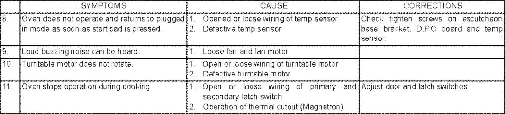
18 11 TroubleShooting Guide 18
19 19
20 20
21 21
NE-1027 NE Microwave Oven. BTQ (U.K.) ETG (Continental Europe) ORDER NO.PHAMOS C2
 ETG (Continental Europe) ORDER NO.PHAMOS C2") ORDER NO.PHAMOS0705021C2 NE-1027 NE-1037 Microwave Oven BTQ (U.K.) ETG (Continental Europe) 2007 Panasonic Home Appliances Microwave Oven (Shanghai) Co., Ltd. All rights reserved. Unauthorized copying
ORDER NO.PHAMOS0705021C2 NE-1027 NE-1037 Microwave Oven BTQ (U.K.) ETG (Continental Europe) 2007 Panasonic Home Appliances Microwave Oven (Shanghai) Co., Ltd. All rights reserved. Unauthorized copying
NN-A574SBBTQ NN-A554WBBTQ NN-A524MBBTQ
 HAD0608002C2 Microwave Oven NN-A574SBBTQ NN-A554WBBTQ NN-A524MBBTQ Power source Power requirements Output (IEC60705) Microwave frequency Timer Oven cavity size Outside dimensions Inside dimensions Weight
TECHNICAL SERVICE GUIDE
 GE Consumer Products TECHNICAL SERVICE GUIDE Microwave Oven MODEL SERIES: JES2251SJ PUB # 31-9129 IMPORTANT SAFETY NOTICE The information in this service guide is intended for use by individuals possessing
BOSCH: HMB5050 (STAINLESS) HMB5060 (BLACK) HMB5020 (WHITE) SIEMENS: HF35M630 (BLACK) Thermador: MBES (STAINLESS) MBEB (BLACK) MBEW (WHITE)
 HMB5060 (BLACK) HMB5020 (WHITE) SIEMENS: HF35M630 (BLACK) Thermador: MBES (STAINLESS) MBEB (BLACK) MBEW (WHITE)") Microwave Oven BOSCH: HMB5050 (STAINLESS) HMB5060 (BLACK) HMB5020 (WHITE) SIEMENS: HF35M630 (BLACK) Thermador: MBES (STAINLESS) MBEB (BLACK) MBEW (WHITE) GAGGENAU: BM 281-610 (STAINLESS) BM 281-630 (ALUMINUM)
Microwave Oven BOSCH: HMB5050 (STAINLESS) HMB5060 (BLACK) HMB5020 (WHITE) SIEMENS: HF35M630 (BLACK) Thermador: MBES (STAINLESS) MBEB (BLACK) MBEW (WHITE) GAGGENAU: BM 281-610 (STAINLESS) BM 281-630 (ALUMINUM)
5. Alignment and Adjustments
 5. Alignment and Adjustments PRECAUTION 1. High voltage is present at the high voltage terminals during any cook cycle. 2. It is neither necessary nor advisable to attempt measurement of the high voltage.
TopPage RCD1200M MODELS
 TopPage RCD00M SERVICE MANUAL S380RCDMP/ COMMERCIAL MICROWAVE OVEN MODELS R-CD00M In the interest of user-safety the oven should be restored to its original condition and only parts identical to those
Technical Service Manual
 Technical Service Manual Microwave Oven GRAIN DIRECTION (ALL PARTS) Model EI24MO45IBA Publication #5995557591 P/N 316439602 January 2010 Basic Information Safe Servicing Practices Avoid personal injury
Service Manual. Microwave Oven. Model: KOR-6L35. S/M No. : OR6L353S001. Caution
 S/M No. : OR6L353S001 Service Manual Microwave Oven Model: KOR-6L35 Caution : In this Manual, some parts can be changed for improving, their performance without notice in the parts list. So, if you need
SERVICE MANUAL R-230KK R-230KW MODELS MICROEAVE OVEN SHARP CORPORATION. No. S2501R230KPKW CONTENTS
 SERVICE MANUAL MODELS No. S2501R230KPKW MICROEAVE OVEN R-230KK R-230KW R-230KK R-230KW In the interest of user-safety the oven should be restored to its original condition and only parts identical to those
SERVICE MANUAL R-1480 R-1481 R-1482 SHARP CORPORATION OVER THE RANGE MICROWAVE OVEN MODELS
 CUSTOM HELP POPCORN COMPU DEFROST POWER LEVEL TURNTABLE ON/OFF WORK LIGHT BREAKFAST SNACKS & REHEAT COMPU COOK KITCHEN TIMER CLOCK STOP CLEAR NIGHT LIGHT 1 Coffee/tea 2 Roll/muffin, fresh 3 Roll/muffin,
CFMV157GS CFMV157GB CFMV157GM CFMV157GQ CFMV157GC
 OVER THE RANGE MICROWAVE OVEN SERVICE MANUAL Models FMV157GS FMV157GB FMV157GM FMV157GQ FMV157GC CFMV157GS CFMV157GB CFMV157GM CFMV157GQ CFMV157GC! ATTENTION! This service manual is intended for use by
ELECTROLUX SERVICE MANUAL
 ELECTROLUX SERVICE MANUAL FMV156DBE S95M241FM156E MODELS OVER THE RANGE MICROWAVE OVEN FMV156DBE FMV56DCF In the interest of user-safety the oven should be restored to its original condition and only parts
Servicing OVER THE RANGE MICROWAVE OVENS. All About. With Standard And Electronic Controls
 All About Servicing OVER THE RANGE MICROWAVE OVENS With Standard And Electronic Controls Electrolux Major Appliances; North America 250 Bobby Jones Expwy Augusta, GA 30907 Publication #5995542437 Part
ELECTROLUX SERVICE MANUAL
 ELECTROLUX SERVICE MANUAL CFMV156DBD S64M242FM156C OVER THE RANGE MICROWAVE OVEN MODELS CFMV156DBD CFMV56DCE In the interest of user-safety the oven should be restored to its original condition and only
ELECTROLUX SERVICE MANUAL
 ELECTROLUX SERVICE MANUAL EI30MH55GSA EI30MH55GSA OVER THE RANGE MICROWAVE OVEN MODELS S87M285MH55GS EI30MH55GSA In the interest of user-safety the oven should be restored to its original condition and
SERVICE MANUAL R-408LS MODEL MICROWAVE OVEN SY612R408LPSTF CONTENTS
 TopPage SERVICE MANUAL MODEL SY612R408LPSTF MICROWAVE OVEN R-408LS In the interest of user-safety the oven should be restored to its original condition and only parts identical to those specified should
SERVICE MANUAL R-409EW R-410EK R-410EW MICROWAVE OVEN MODELS SHARP ELECTRONCS CORPORATION
 SERVICE MANUAL R-409EW S21M160R409EE R-409EW MODELS MICROWAVE OVEN R-409EW In the interest of user-safety the oven should be restored to its original condition and only parts identical to those specified
MICROWAVE OVEN SERVICE MANUAL
 Internal Use Only Website http://us.lgservice.com MICROWAVE OVEN SERVICE MANUAL MODEL: LCS1410SW CAUTION BEFORE SERVICING THE UNIT, READ THE SAFETY PRECAUTIONS IN THIS MANUAL. P/NO : MFL06272520 November,
GLMB209DBC GLMB209DQC GLMB209DSC PLMB209DCD
 Product No. GLMB209DBC GLMB209DQC GLMB209DSC PLMB209DCD Market North America North America North America North America Color black bisque white stainless steel Volts 120 120 120 120 Watts 1200 1200 1200
SERVICE MANUAL R-203BW R-209BK R-220BW SHARP CORPORATION MICROWAVE OVEN MODELS
 SERVICE MANUAL R-203BW S1803R220BPW/ EXPRESS MINUTE DEFROST PLUS SNACKS POPCORN BEVERAGE COOKING BAKED FRESH POTATO VEGETABLES DINNER PLATE REHEATING ROLL, MUFFIN MODELS MICROWAVE OVEN R-203BW 1 2 3 4
SERVICE MANUAL R-209HK R-209HW SHARP CORPORATION MICROWAVE OVEN MODELS
 SERVICE MANUAL R-209HK S2304R209HPW/ MICROWAVE OVEN MODELS R-209HK In the interest of user-safety the oven should be restored to its original condition and only parts identical to those specified should
THERMADOR BUILT-IN OVENS
 SERVICE MANUAL for THERMADOR BUILT-IN OVENS Model CM302S MODELS: CM301B / CM301W / CM301S CM302B / CM302W / CM302S Lit. No. 94-30-006B August, 2000 CM Oven Service Manual Table of Contents Lit. No. 94-30-006B
MICROWAVE OVEN SERVICE MANUAL
 Website: http://biz.lgservice.com MICROWAVE OVEN SERVICE MANUAL MODEL: MG-556EL/MG-556EJ CAUTION BEFORE SERVICING THE UNIT, READ THE SAFETY PRECAUTIONS IN THIS MANUAL. SAFETY PRECAUTIONS This device is
ELECTROLUX SERVICE MANUAL
 ELECTROLUX SERVICE MANUAL GLMV169GSB PLMVZ169GCB S37M277MV169G OVER THE RANGE MICROWAVE OVENS MODELS GLMV169GSA GLMV169GSB GLMV169GBA GLMV169GQA BLMV169GQB PLMVZ169GCA PLMVZ169GCB PLMVZ169GCB PLMVZ169GCC
BERTAZZONI SERVICE MANUAL KO30 PRO X MODEL
 LIGHT HI/LO FAN HI/LO STOP CLEAR START ADD A MINUTE KO30 PRO X BERTAZZONI SERVICE MANUAL MODEL KO30 PRO X S41M333KO30PR TABLE OF CONTENTS Page PRECAUTIONS TO BE OBSERVED BEFORE AND DURING SERVICING TO
SERVICE MANUAL COOK MODELS
 SERVICE MANUAL S72M194DMOS2E C C COOK MODELS MICROWAVE OVEN C C In the interest of user-safety the oven should be restored to its original condition and only parts identical to those specified should be
MICROWAVE OVEN SERVICE MANUAL
 Internal Use Only Website: http://biz.lgservice.com MICROWAVE OVEN SERVICE MANUAL MODEL: MH-6387AR CAUTION BEFORE SERVICING THE UNIT, READ THE SAFETY PRECAUTIONS IN THIS MANUAL. P/NO : MFL32188507 August,
SERVICE MANUAL R-430DK R-430DW R-430DQ R-440DK R-440DW MICROWAVE OVEN MODELS SHARP ELECTRONCS CORPORATION
 R-430D SERVICE MANUAL MODELS MICROWAVE OVEN R-430DK R-430DK S70M147R430DE In the interest of user-safety the oven should be restored to its original condition and only parts identical to those specified
NN-ST340W NN-ST340M. Microwave Oven CPH (CANADA) RPH (MEXICO & LATIN AMERICA) ORDER NO.PHAMOS CE E1
 RPH (MEXICO & LATIN AMERICA) ORDER NO.PHAMOS CE E1") ORDER NO.PHAMOS1101009CE E1 NN-ST340W NN-ST340M Microwave Oven CPH (CANADA) RPH (MEXICO & LATIN AMERICA) Panasonic Home Appliances Microwave Oven (Shanghai) Co., Ltd. 2011. 2 CONTENTS Page Page 1 FEATURE
ORDER NO.PHAMOS1101009CE E1 NN-ST340W NN-ST340M Microwave Oven CPH (CANADA) RPH (MEXICO & LATIN AMERICA) Panasonic Home Appliances Microwave Oven (Shanghai) Co., Ltd. 2011. 2 CONTENTS Page Page 1 FEATURE
Service Training Manual
 R Commercial Service Training Manual RFS Models RFS - 60 Hz August 2011 16400013 Amana is a Registered Trademark of Maytag Corporation. Brand used under license. 1 2011 RFS Training Manual.indd 1 10/3/2011
SERVICE MANUAL R-320BB R-320BK R-320BW SHARP CORPORATION MICROWAVE OVEN MODELS
 SERVICE MANUAL R-320BB S2805R320BPW/ MODELS MICROWAVE OVEN R-320BB In the interest of user-safety the oven should be restored to its original condition and only parts identical to those specified should
SERVICE MANUAL R-630DK R-630DW R-630DS SHARP CORPORATION MICROWAVE OVEN MODELS
 Bar Help SERVICE MANUAL MICROWAVE OVEN R-630DK S7017R630DPW/ Breakfast Linch on One Dish Popcorn Baked Sensor Custom the Run Dinners Potatoes Reheat More from your Microwave Sensor Cooking Beverage Vegetables
MICROWAVE OVEN SERVICE MANUAL
 Website http://biz.lgservice.com MICROWAVE OVEN SERVICE MANUAL MODEL: MH-1446SQP CAUTION BEFORE SERVICING THE UNIT, READ THE SAFETY PRECAUTIONS IN THIS MANUAL. P/NO : MFL36414401 October, 2006 Printed
SERVICE MANUAL R-408JK R-408JW MICROWAVE OVENS MODELS SHARP ELECTRONCS CORPORATION. Service Headquarters: Sharp Plaza, Mahwah, New Jersey,
 SERVICE MANUAL R-408JK S24M231R408JE MODELS MICROWAVE OVENS R-408JK In the interest of user-safety the oven should be restored to its original condition and only parts identical to those specified should
MICROWAVE OVEN HOOD COMBINATION
 SERVICE MANUAL for the MICROWAVE OVEN HOOD COMBINATION ( E Model Line) March, 1997 Printed in U.S.A. LIT4317216 THIS MANUAL CONTAINS INFORMATION NECES- SARY FOR SERVICING THE KITCHENAID MICRO- WAVE OVEN
ELECTROLUX SERVICE MANUAL
 ELECTROLUX SERVICE MANUAL 318279510 S65M254318279 MODELS MICROWAVE OVENS 318279510 In the interest of user-safety the oven should be restored to its original condition and only parts identical to those
SERVICE MANUAL MODELS
 SERVICE MANUAL DMT2420B S12M201DMT24E MICROWAVE OVEN MODELS DMT2420B In the interest of user-safety the oven should be restored to its original condition and only parts identical to those specified should
THERMADOR BUILT-IN OVENS MODELS:
 SERVICE MANUAL for THERMADOR BUILT-IN OVENS MODELS: CJ302B / CJ302W / CJ302S Lit No. 94-30-007A 2001 BSH Home Appliances Corp. October 2001 CJ Oven Service Manual Table of Contents Lit. No. 94-30-007A
BERTAZZONI SERVICE MANUAL MO30 STA NE MICROWAVE OVEN
 BERTAZZONI SERVICE MANUAL MO30 STA NE S31M332MO30ST MICROWAVE OVEN MO30 STA NE In the interest of user-safety the oven should be restored to its original condition and only parts identical to those specified
FMV156DBF FMV156DCG FMV156DQF FMV156DSF
 Product No. BF CG QF SF Market North America North America North America North America Color black stainless bisque white Volts 120 120 120 120 Watts 950 950 950 950 Wiring Diagram 5995503470 5995503470
SERVICE MANUAL R-21JCA-F SHARP CORPORATION LIGHT DUTY COMMERCIAL MICROWAVE OVENS MODEL
 TIME GUIDE FOR ONE SERVING A B C T S R Q I J K L M N O P R-21JCA-F SERVICE MANUAL S0514R21JCPAF LIGHT DUTY COMMERCIAL MICROWAVE OVENS 1000W/ R-21JCA MODEL R-21JCA-F 15-30 sec. 30-60 sec. Bagel, Roll Hot
OVEN PARTS For Models: JMW9530DAW30, JMW9530DAS30 (White) (Stainless)
 (Stainless)") OVEN PARTS 30" BUILT IN ELECTRIC COMBO CONVECTION 11 09 Litho in U.S.A. (LANK) (eeb) 1 Part No. Rev. A OVEN PARTS 1 Literature Parts 8101P602 60 Installation Instructions W10169642 Owners Manual 9762761
OVEN PARTS 30" BUILT IN ELECTRIC COMBO CONVECTION 11 09 Litho in U.S.A. (LANK) (eeb) 1 Part No. Rev. A OVEN PARTS 1 Literature Parts 8101P602 60 Installation Instructions W10169642 Owners Manual 9762761
MICROWAVE OVEN SERVICE MANUAL
 Website http://us.lgservice.com MICROWAVE OVEN SERVICE MANUAL MODEL: LCRM1240SW LCRM1240SB LCRM1240ST CAUTION BEFORE SERVICING THE UNIT, READ THE SAFETY PRECAUTIONS IN THIS MANUAL. P/NO : 3828W5S3848 July,
ORDER NO.PAPMOSH CE E1. Microwave Oven NN-ST663S CPH (CANADA) Panasonic Appliances Microwave Oven (Shanghai) Co., Ltd
 Panasonic Appliances Microwave Oven (Shanghai) Co., Ltd") ORDER NO.PAPMOSH1301002CE E1 NN-ST663S Microwave Oven CPH (CANADA) Panasonic Appliances Microwave Oven (Shanghai) Co., Ltd. 2013. 2 NN-ST663S 3 CONTENTS Page Page 1 SCHEMATIC DIAGRAM 5 2 DESCRIPTION OF
ORDER NO.PAPMOSH1301002CE E1 NN-ST663S Microwave Oven CPH (CANADA) Panasonic Appliances Microwave Oven (Shanghai) Co., Ltd. 2013. 2 NN-ST663S 3 CONTENTS Page Page 1 SCHEMATIC DIAGRAM 5 2 DESCRIPTION OF
FMV156DBB FMV156DCC FMV156DQB FMV156DSB
 Product No. BB CC QB SB Market North America North America North America North America Color black stainless steel bisque white Volts 120 120 120 120 Watts 950 950 950 950 Wiring Diagram 5995451720 5995451720
Custom Help. Minute Plus Compu Defrost. Sensor. Cook MODEL. Compu. Compu. Roast. High Mix
 Sensor Reheat 1 Baked potatoes 2 Frozen vegetables 3 Fresh veg-soft 4 Fresh veg-hard 5 Frozen entrees 6 Hot dogs 7 Bacon 8 Fish, seafood Minute Plus Compu Defrost Convecvtion 1 Hamburgers 2 Chicken pieces
Service Manual NN-G61 AR. Microwave Oven. Specifications. 220 V AC, 50 Hz. Power Source: Output: Microwave: 900 W: Full Power (IEC )
") ORDER NO. DCS-JUL2002-002-MS Service Manual Microwave Oven Specifications Power Source: 220 V AC, 50 Hz Power requirement: Microwave: 1.450 W Heater: 860 W Output: Microwave: 900 W: Full Power (IEC 705-88)
ORDER NO. DCS-JUL2002-002-MS Service Manual Microwave Oven Specifications Power Source: 220 V AC, 50 Hz Power requirement: Microwave: 1.450 W Heater: 860 W Output: Microwave: 900 W: Full Power (IEC 705-88)
MICROWAVE OVEN SERVICE MANUAL
 http://www.lgeservice.com E-mail:Techsupport@LGEservice.com MICROWAVE OVEN SERVICE MANUAL MODEL : LTM9000W/LTM9000B CAUTION BEFORE SERVICING THE UNIT, READ THE SAFETY PRECAUTIONS IN THIS MANUAL. CAUTION
DCM24 Convection Microwave. Oven and Cabinet Control Panel Door
 DCM24 Convection Microwave Oven and Cabinet Control Panel Door Miscellaneous Complete Parts List DCM - OVEN AND CABINET DCM DOOR door parts 5-66509B Door full assy 5-66509B Door full assy 5-66509R Door
! WARNING To avoid risk of electrical shock, personal injury or death; disconnect power to oven before servicing, unless testing requires power.
 Technical Information Gas Slide-In Range JGS8750ADB/S/W JGS8850ADB/Q/S/W Due to possibility of personal injury or property damage, always contact an authorized technician for servicing or repair of this
S/M No. : T150S0A003. Service Manual. Microwave Oven. Model: KOT-150S0A KOT-151S0A KOT-152U0A KOT-152C0A KOT-155S0A
 S/M No. : T150S0A003 Service Manual Microwave Oven Model: KOT-150S0A KOT-151S0A KOT-152U0A KOT-152C0A KOT-155S0A DAEWOO ELECTRONICS CO., LTD. http : //svc.dwe.co.kr Feb. 2002 PRECAUTIONS TO BE OBSERVED
International Countertop Commercial Microwave Ovens MENUMASTER C O M M E R C I A L M I C R O W A V E
 MENUMASTER C O M M E R C I A L M I C R O W A V E O V E N R Service This manual is to be used by qualified appliance technicians only. Maytag does not assume any responsibility for property damage or personal
EI30MH55GBA EI30MH55GSA EI30MH55GWA EI30MH55GZA
 Product No. BA SA WA ZA Market North America North America North America North America Color black stainless steel white white/black Volts 120 120 120 120 Watts 1200 1200 1200 1200 Wiring Diagram 5995509899
Wiring Diagram Owner's Guide Installation Instructions Service Data Sheet
 Product No. 39257773D90S1 Series 27" elec Color stainless Market North America Wiring Diagram 318046267 Owner's Guide 3182059 Installation Instructions 318201533 Service Data Sheet 318047455 FPMC2785KF.jp$
SERVICE MANUAL R-1750 R-1751 R-1752 R-1754 SHARP CORPORATION OVER THE RANGE MICROWAVE OVEN MODELS
 MINUTE PLUS Meats T O U C H S C R E E N 6 Categories + 36 Foods START Vegetables Poultry Frozen Food Turntable On/Off SENSOR Reheat Popcoon Baked Potatoes MORE FROM YOUR MICROWAVE Set Up SERVICE MANUAL
MICROWAVE OVEN SERVICE MANUAL
 website http://www.lgservice.com e-mail http://www.lgeservice.com/techsup.html MICROWAVE OVEN SERVICE MANUAL MODEL: MV1526W MV1526B CAUTION BEFORE SERVICING THE UNIT, READ THE SAFETY PRECAUTIONS IN THIS
TABLE OF CONTENTS. Commercial Microwave Oven
 Order Number MOD1206355CE Commercial Microwave Oven Model No. NE-1252 Model No. NE-1752 Model No. NE-1772 Model No. NE-2152 Model No. NE-12521 Model No. NE-12523 Model No. NE-17521 Model No. NE-17523 Model
GLMV169DBF PLMV169DCG
 Product No. GLMV169DBF PLMV169DCG Market North America North America Color black stainless steel Volts 120 120 Watts 1000 1000 Wiring Diagram 5995503835 5995503835 Owner's Guide TINSEB478MRR0 TINSEB478MRR0
SERVICE MANUAL SHARP ELECTRONICS CORPORATION OVER THE RANGE MICROWAVE OVEN MODELS R-1850 R-1851
 SERVICE MANUAL R-850 S6804R850X// OVER THE RANGE MICROWAVE OVEN MODELS R-850 In the interest of user-safety the oven should be restored to its original condition and only parts identical to those specified
6900-( )-( ) HIGH SPEED SANDWICH PRESS
-( ) HIGH SPEED SANDWICH PRESS") SERVICE MANUAL 6900-( )-( ) HIGH SPEED SANDWICH PRESS CAUTION PRECAUTIONS TO BE OBSERVED BEFORE AND DURING SERVICING TO AVOID POSSIBLE EXPOSURE TO EXCESSIVE MICROWAVE ENERGY (a) Do not operate or allow
SERVICE MANUAL 6900-( )-( ) HIGH SPEED SANDWICH PRESS CAUTION PRECAUTIONS TO BE OBSERVED BEFORE AND DURING SERVICING TO AVOID POSSIBLE EXPOSURE TO EXCESSIVE MICROWAVE ENERGY (a) Do not operate or allow
VMOC205 : ELECTRICAL COMPONENTS [1/6]
![VMOC205 : ELECTRICAL COMPONENTS [1/6]](/thumbs/93/111162439.jpg "VMOC205 : ELECTRICAL COMPONENTS [1/6]") VMOC205 : 001 - ELECTRICAL COMPONENTS [1/6] Page 1 of 12 VMOC205 : 001 - ELECTRICAL COMPONENTS [1/6] Ref # Part Number Qty. Description 1 PM100029 POWER SUPPLY CORD 2 PM100030 MONITOR FUSE 20A & MONITOR
VMOC205 : 001 - ELECTRICAL COMPONENTS [1/6] Page 1 of 12 VMOC205 : 001 - ELECTRICAL COMPONENTS [1/6] Ref # Part Number Qty. Description 1 PM100029 POWER SUPPLY CORD 2 PM100030 MONITOR FUSE 20A & MONITOR
MICROWAVE OVEN SERVICE MANUAL
 website http://biz.lgservice.com e-mail http://www.lgeservice.com/techsup.html MICROWAVE OVEN SERVICE MANUAL MODEL: LMV1314B LMV1314W LMV1314SV CAUTION BEFORE SERVICING THE UNIT, READ THE SAFETY PRECAUTIONS
SERVICE MANUAL R-3S68 SHARP CORPORATION MICROWAVE OVEN MODEL
 SERVICE MANUAL S3612R3S68PX/ MICROWAVE OVEN MODEL In interests of user-safety the oven should be restored to its original condition and only parts identical to those specified should be used. TALE OF CONTENTS
TECHNICAL SERVICE GUIDE
 GE Consumer & Industrial TECHNICAL SERVICE GUIDE Over the Range Microwave Oven MODEL SERIES: JVM2070_H PUB # 31-9111 2/04 ! IMPORTANT SAFETY NOTICE The information in this service guide is intended for
SERVICE MANUAL KB-3425LS KB-3425LK KB-3425LW
 SERVICE MANUAL FREE STANDING/SLIDE-IN RANGE WITH MICROWAVE DRAWER KB-3425LS/K/W S66R264KB442L MODELS KB-4425LW pictured KB-3425LS KB-3425LK KB-3425LW KB-4425LS KB-4425LK KB-4425LW WARNING TO SERVICE PERSONNEL:
NN-GF560M. Microwave Oven. RPM(Chile, Peru, Uruguay, Paraguay etc.) ORDER NO.PHAMOS C3
 ORDER NO.PHAMOS C3") ORDER NO.PHAMOS1006050C3 NN-GF560M Microwave Oven RPM(Chile, Peru, Uruguay, Paraguay etc.) Panasonic Home Appliances Microwave Oven (Shanghai) Co., Ltd. 2010. 2 3 NN-GF560M CONTENTS Page Page 1 FEATURE
ORDER NO.PHAMOS1006050C3 NN-GF560M Microwave Oven RPM(Chile, Peru, Uruguay, Paraguay etc.) Panasonic Home Appliances Microwave Oven (Shanghai) Co., Ltd. 2010. 2 3 NN-GF560M CONTENTS Page Page 1 FEATURE
ORDER NO.PAPMOSH CE E1. Microwave Oven NN-SD773S NN-SD763S CPH (CANADA) Panasonic Home Appliances Microwave Oven (Shanghai) Co., Ltd
 Panasonic Home Appliances Microwave Oven (Shanghai) Co., Ltd") ORDER NO.PAPMOSH1301004CE E1 NN-SD773S NN-SD763S Microwave Oven CPH (CANADA) Panasonic Home Appliances Microwave Oven (Shanghai) Co., Ltd. 2013. 2 NN-SD773S / NN-SD763S 3 CONTENTS Page Page 1 SCHEMATIC
ORDER NO.PAPMOSH1301004CE E1 NN-SD773S NN-SD763S Microwave Oven CPH (CANADA) Panasonic Home Appliances Microwave Oven (Shanghai) Co., Ltd. 2013. 2 NN-SD773S / NN-SD763S 3 CONTENTS Page Page 1 SCHEMATIC
OVER-THE-COUNTER MICROWAVE OVEN
 KAC-36 TECHNICAL EDUCATION OVER-THE-COUNTER MICROWAVE OVEN Model KOMS155MBL JOB AID 4317340 FORWARD This KitchenAid Job Aid, Over-The-Counter Microwave Oven, (Part No. 4317340), provides the technician
! WARNING To avoid risk of electrical shock, personal injury or death; disconnect power to oven before servicing, unless testing requires power.
 Technical Information Electric Slide-In Range JES9750AAB/S/W JES9800AAB/Q/S/W JES9860AAB/S/W Due to possibility of personal injury or property damage, always contact an authorized technician for servicing
NN-SN973S NN-SN943B NN-SN943W NN-SN933B NN-SN933W
 ORDER NO.PAPMOSH1301006CE E1 NN-SN973S NN-SN943B NN-SN943W NN-SN933B NN-SN933W Microwave Oven APH (USA) Panasonic Appliances Microwave Oven (Shanghai) Co., Ltd. 2013. 2 3 NN-SN973S / NN-SN943B / NN-SN943W
Microwave. Technical Bulletin. SUBJECT: Service manual correction. Number: MW-174 Date: July Model(s): R-1850/51, R1855A, R1870/71/72
: R-1850/51, R1855A, R1870/71/72") Microwave Technical Bulletin Sharp Electronics Corporation Services and Support Group 1300 Naperville Drive Romeoville, IL 60446 Number: MW-174 Date: July 2003 Model(s): R-1850/51, R1855A, R1870/71/72
Microwave Technical Bulletin Sharp Electronics Corporation Services and Support Group 1300 Naperville Drive Romeoville, IL 60446 Number: MW-174 Date: July 2003 Model(s): R-1850/51, R1855A, R1870/71/72
Service Manual. Microwave Oven. Model: KOR-6C275S. S/M No. : R6C275S001. Caution
 S/M No. : R6C275S001 Service Manual Microwave Oven Model: KOR-6C275S Caution : In this Manual, some parts can be changed for improving, their performance without notice in the parts list. So, if you need
NN-S262SF NN-S262BF NN-S262WF NN-S252BF NN-S252WF
 ORDER NO.SIMMC 0203005C1 E2 NN-S262SF NN-S262BF NN-S262WF NN-S252BF NN-S252WF Microwave Oven APH(USA) CPH(CANADA) 2002 Shanghai Matsushita Microwave Oven Co., Ltd. All rights reserved. Unauthorized copying
CAUTION All safety information must be followed as provided in Service Manual
 Double Oven Gas Range Technical Information MGR6875AD* Due to possibility of personal injury or property damage, always contact an authorized technician for servicing or repair of this unit. Refer to Service
SERVICE MANUAL R-211A SHARP CORPORATION MICROWAVE OVEN MODEL
 MED DEFROS DEFROST (Kg) 1 kg HIGH 0.5 kg R-211A SERVICE MANUAL S5709R211APX/ MICROWAVE OVEN COOKING CONTROL 30 25 20 TIMER 0 5 10 15 OPEN DOOR MODEL R-211A In interests of user-safety the oven should be
OVER-RANGE MICROWAVE. Model No. FMV145K
 Product No. B2 S2 Color black white Market North America North America Owner's Guide 316137205 316137205 Installation Instructions 316137211 316137211 Mini Service Manual 5304409006 5304409006 Wiring Diagram
OVEN PARTS For Model: KEMS378BBL3, KEMS378BWH3, KEMS378BAL3 (Black) (White) (Almond)
 (White) (Almond)") 27" BUILT IN ELECTRIC DOUBLE OVEN THERMAL CONVECTION LOWER MICROWAVE CONVECTION UPPER OVEN PARTS 1 95 Litho in U.S.A.(jcn) 1 Part No. 1 Side Trim, Door 3187874 Black Model 3188827 White Model 3187880 Almond
27" BUILT IN ELECTRIC DOUBLE OVEN THERMAL CONVECTION LOWER MICROWAVE CONVECTION UPPER OVEN PARTS 1 95 Litho in U.S.A.(jcn) 1 Part No. 1 Side Trim, Door 3187874 Black Model 3188827 White Model 3187880 Almond
Section 7 - Troubleshooting Guide
 Section 7 - Troubleshooting Guide Section 7 - Troubleshooting Guide IMPORTANT While this troubleshooting guide provides information to aid in troubleshooting problems with the range, it does not contain
ELECTRIC FENCE ENERGIZER SERVICE MANUAL MODEL 950 SERVICE MANUAL FOR OLLI 950 FENCE ENERGIZERS
 ELECTRIC FENCE ENERGIZER MODEL 950 SERVICE MANUAL Service Manual for OLLI 950 Page 1/16 Date 20.10.2014 Table of Contents...1 1. IMPORTANT SAFETY INSTRUCTIONS...2 2. SPECIFICATIONS...3 3. CONSTRUCTION...4
SERVICE. Manual MICROWAVE OVEN CM1319 / CM1329 CM1619 / CM1629 CM1919 / CM1929 SESC. 1. Precaution. 2. Specifications. 3. Operating Instructions
 P 1 2 3 4 5 6 7 8 9 0 + 20sec MICROWAVE OVEN CM1319 / CM1329 CM1619 / CM1629 CM1919 / CM1929 SERVICE Manual MICROWAVE OVEN CONTENTS 1. Precaution 2. Specifications 3. Operating Instructions 4. Disassembly
Evolution. For all Evolution models manufactured from January Part No. 32Z3382e Issue No. 3 CAUTION MICROWAVE EMISSIONS
 Evolution S E R V I C E M A N U A L For all Evolution models manufactured from January 2001 Part No. 32Z3382e Issue No. 3 SERVICE MANUAL CAUTION MICROWAVE EMISSIONS DO NOT BECOME EXPOSED TO EMISSIONS FROM
Number: MW-181 Date: November 2004
 Technical Bulletin Microwave Sharp Electronics Corporation Services and Support Group 1300 Naperville Drive Romeoville, IL 044 Number: MW-181 Date: November 2004 Model(s): R1500 / R1501 / R1502 / R1505
Microcook. For all Microcook models manufactured from January Part No. 32Z3385e Issue No. 3 CAUTION MICROWAVE EMISSIONS
 Microcook S E R V I C E M A N U A L For all Microcook models manufactured from January 2001 Part No. 32Z3385e Issue No. 3 SERVICE MANUAL CAUTION MICROWAVE EMISSIONS DO NOT BECOME EXPOSED TO EMISSIONS FROM
PCOR30 Microwave Oven
 PCOR30 Microwave Oven Page # Description 2 Door Assembly 3 Control Panel Assembly 4 Hardware/Wiring Harnesses/Accessories 5-8 Oven and Cabinet Parts Revised 09-20-2011 PCOR30 Microwave Door Assembly 4-35
SERVICE MANUAL R-21LCF MODEL LIGHT DUTY COMMERCIAL MICROWAVE OVEN SHARP CORPORATION R21LCF S7607R21LCFP/ CONTENTS
 C B A I J K L M N O T P S R Q 1000W/ R-21LC C O M M E R C I A L M I C R O W A V E O V E N TIME GUIDE FOR ONE SERVING 15-30 sec. 30-60 sec. Bagel, Roll Hot Dog Muffin, Pastry Pizza Slice Pie Slice Small
MICROWAVE OVEN SERVICE MANUAL
 website http://www.lgservice.com MICROWAVE OVEN SERVICE MANUAL MODEL: LMVM1945SW LMVM1945SB LMVM1945SBQ LMVM1945T CAUTION BEFORE SERVICING THE UNIT, READ THE SAFETY PRECAUTIONS IN THIS MANUAL. CAUTION
Notice Regarding this Upgrade. WARNING! Danger Potential
 Notice Regarding this Upgrade WARNING! Danger Potential Although this kit has been designed to be easy-to-install, and has been tested in many installations; caution must be exercised when installing this
Maintenance Manual 13 AMPERE POWER SUPPLY 19A704647P1-P3. Mobile Communications LBI-31801C
 C Mobile Communications 13 AMPERE POWER SUPPLY 19A704647P1-P3 CAUTION THESE SERVICING INSTRUCTIONS ARE FOR USE BY QUALI- FIED PERSONNEL ONLY. TO AVOID ELECTRIC SHOCK DO NOT PERFORM ANY SERVICING OTHER
SERVICE MANUAL (DOMESTIC & INTERNATIONAL)
") SERVICE MANUAL (DOMESTIC & INTERNATIONAL) DUAL TECHNOLOGY FINISHER MODEL 1960 & 1980 SERIES Lincoln Foodservice Products, LLC 1111 North Hadley Road Fort Wayne, Indiana 46804 United States of America Telephone:
SERVICE MANUAL (DOMESTIC & INTERNATIONAL) DUAL TECHNOLOGY FINISHER MODEL 1960 & 1980 SERIES Lincoln Foodservice Products, LLC 1111 North Hadley Road Fort Wayne, Indiana 46804 United States of America Telephone:
Safe-T-element Installation Instructions
 Safe-T-element Installation Instructions For: PTI STEZA (2x2 Burner Configuration) & PTI STEZB (3x1 Burner Configuration) Revision K (May. 3 2012) TABLE OF CONTENTS 1. PREPARATION... 3 1.1 General Safety
ARTICLE BEGINNING SERVICE PRECAUTIONS
 Page 1 of 96 ARTICLE BEGINNING SERVICE PRECAUTIONS WARNING: WARNING: CAUTION: When performing any inspection or service procedure on this vehicle, ensure following service precautions are followed to prevent
SERVICE MANUAL R-1210 R-1211 SHARP CORPORATION OVER THE COUNTER MICROWAVE OVEN MODELS
 SERVICE MANUAL R-20 S2203R50X// SENSOR MODELS OVER THE COUNTER MICROWAVE OVEN R-20 In the interest of user-safety the oven should be restored to its original condition and only parts identical to those
! WARNING To avoid risk of electrical shock, personal injury, or death, disconnect power to range before servicing, unless testing requires power.
 Electric Freestanding Range Technical Information MER5875RA* Due to possibility of personal injury or property damage, always contact an authorized technician for servicing or repair of this unit. Refer
PRECAUTIONS TO BE OBSERVED BEFORE AND DURING SERVICING TO AVOID POSSIBLE EXPOSURE TO EXCESSIVE MICROWAVE ENERGY
 MIN SEC 150w 450w FILE No. SERVICE MANUAL STAINLESS STEEL EM-SL0NECO MICROWAVE OVEN WITH GRILL MIN SEC AUTO 150w 450w AUTO C C / Kg / Kg Product Code No. EM-SL0NECO 1-47-574-5 FOREWORD Read this manual
Service Manual. Microwave Oven. Model: KOR-63D79S KOR-63D70S KOR-63F79S KOR-63F70S DAEWOO ELECTRONICS CO., LTD.
 S/M No. : R63D79S002 Service Manual Microwave Oven Model: KOR-63D79S KOR-63D70S KOR-63F79S KOR-63F70S Caution : In this Manual, some parts can be changed for improving, their performance without notice
OVEN PARTS For Models: RMC305PVB01, RMC305PVQ01, RMC305PVT01, RMC305PVS01 (Black) (White) Biscuit) (Stainless)
 (White) Biscuit) (Stainless)") OVEN PARTS 30" BUILT IN ELECTRIC COMBO SENSOR/SC 3 12 Litho in U.S.A. (BMN)(bay) 1 Part No. Rev. C OVEN PARTS 1 Literature Parts W10192051 Installation Instructions W10192044 Use & Care Guide (Microwave)
OVEN PARTS 30" BUILT IN ELECTRIC COMBO SENSOR/SC 3 12 Litho in U.S.A. (BMN)(bay) 1 Part No. Rev. C OVEN PARTS 1 Literature Parts W10192051 Installation Instructions W10192044 Use & Care Guide (Microwave)
Installation Instructions
 Installation Instructions For PTI STEZA C (2x2 Burner Configuration) & PTI STEZB C (3x1 Burner Configuration) Revision E Safe-T-Element Installation Instructions Table of Contents 1. PREPARATION..3 1.1
! WARNING To avoid risk of electrical shock, personal injury or death; disconnect power to oven before servicing, unless testing requires power.
 Technical Information Double Oven Dual Fuel Range JDR8895AAB/S/W Due to possibility of personal injury or property damage, always contact an authorized technician for servicing or repair of this unit.
BRIVIS DUCTED INVERTER SERVICE MANUAL DRCi
 BRIVIS DUCTED INVERTER SERVICE MANUAL DRCi 1 TABLE OF CONTENTS TABLE OF CONTENTS... 2 IMPORTANT NOTE... 3 FAULT FINDING AND DIAGNOSTICS... 3 ABBREVIATIONS... 3 PCB S... 4 OUTDOOR MAIN PCB... 4 INDOOR PCB...
PROBLEM SOLVING GUIDE ELMECO SLUSH MACHINE MODEL FCM
 A01 INSTRUCTIONS ON HOW TO READ REFERENCES...2 A10 FEATURES AND TECHNICAL SPECIFICATIONS...3 A15 RECOMMENDED PREVENTIVE MAINTENANCE SPARE PARTS KIT...3 A20 IMPORTANT INFORMATION ON FUNCTIONALITY OF THE