Wire Harness Installation Instructions Manual #90571 PART 1 For Installing: #10309 Basic Customizable Nostalgia All Black Chassis Harness 17 Circuit
|
|
|
- Shanon Moore
- 5 years ago
- Views:
Transcription

1 Wire Harness Installation Instructions Manual #90571 PART 1 For Installing: #10309 Basic Customizable Nostalgia All Black Chassis Harness 17 Circuit Painless Performance Products recommends you, the installer, read this installation manual from front to back before installing this harness. Due to the variables in modifications that can be done to vehicles, reading this manual will give you considerable insight on the proper installation of this harness.
2 Perfect Performance Products, LLC Painless Performance Products Division 2501 Ludelle Street Fort Worth, TX phone fax Web Site: If you have any questions concerning the installation of this harness, feel free to call Painless Performance Products' tech line at Calls are answered from 8am to 5pm central time, Monday thru Thursday, 8am to4:30pm Fridays, except holidays. We have attempted to provide you with as accurate instructions as possible, and are always concerned about corrections or improvements that can be made. If you have found any errors or omissions, or if you simply have comments or suggestions concerning these instructions, please write us at the address above, send us a fax at (817) or e- mail us at painless@painlessperformance.com. We sincerely appreciate your business. Perfect Performance Products, LLC shall in no event be liable in contract or tort (including negligence) for special, indirect, incidental, or consequential damages, such as but not limited to, loss of property damage, or any other damages, costs or expenses which might be claimed as the result of the use or failure of the goods sold hereby, except only the cost of repair or replacement Installation Manual January 14, 2014 Copyright 2013 by Perfect Performance Products, LLC 2
3 CAUTION: BEFORE THE REMOVAL OF YOUR ORIGINAL HARNESS AND/OR THE INSTALL OF YOUR NEW PAINLESS HARNESS, DISCONNECT THE POWER FROM YOUR VEHICLE BY REMOVING THE NEGATIVE OR POSITIVE BATTERY CABLE FROM THE BATTERY.THE BATTERY IS NOT TO BE CONNECTED UNTIL THE PAINLESS HARNESS HAS BEEN INSTALLED AND TESTED. A full color copy of these instructions can be found online at If your vehicle has an existing harness, you will want to retain it for the possible re-use of various pigtails & connector housings particular to your application. During the removal process, avoid making any unnecessary cuts. This harness is universal in nature, meaning, all ends are left open to allow you to cut wire to length and install the appropriate connection. The package of terminals included with the harness will enable you to make connections. Only printed wires will have a 900-series number. These 900-series numbers are used to identify various wires and circuits in the wiring diagrams that are a part of these instructions. In the event that there are unused or unconnected wires, the ends of all wires labeled in this instruction manual as POWER or wires printed with B+ in the description, will need to have the ends terminated with an insulated terminal or taped. Doing so will prevent the wires shorting and causing harness failure or fire. 3
4 TABLE OF CONTENTS PAGE # SECTION 6 INTRODUCTION 7 CONTENTS 8 SMALL PARTS 9 TOOLS NEEDED 10 PRE-INSTALLATION GUIDELINES 11 INSTALLING FACTORY TERMINALS 12 GROUNDS 15 FUSE BLOCK Horn relay Flashers 16 Fuse Identification 17 Relays & Switches 18 Fuse Block Mounting 20 FUSE BLOCK HARNESS ROUTING 22 COMPONENT OUTPUT HARNESS ROUTING 24 HEADLIGHT SECTION CONNECTIONS Left/Driver Side Headlight 26 Headlight w/ Pigtails 28 Left Turn/Park Light 29 Horn Right Turn/Park Light, Right Headlight 31 ENGINE / IGNITION SECTION Coil/ignition 32 Ballast Bypass 33 Tachometer 35 Engine Sending Units/Switches Coolant Temperature 37 Oil Pressure, Choke 39 START/CHARGE SECTION Alternator 40 Charge Indicator Light 42 GM SI Series Alternators 43 GM CS-130 Alternators 45 GM CS-130D Alternators 47 GM Externally Regulated Alternator 48 Ford Externally Regulated Alternator 49 Ford Internally Regulated Alternator (3G) 50 MOPAR Externally Regulated Alternator 52 MIDI Fuse 54 Starter 4
5 Schematics, Diagrams, & Photos PAGE # SECTION 6 NOTES diagram 7 CONTENTS photo 9 JAW STYLE CRIMPERS picture 11 TERMINAL INSTALLATION pictures 13 GOOD & BAD GROUND SOURCE diagrams 14 GROUND SCHEMATIC 16 FUSE IDENTIFICATION diagrams 18 FUSE BLOCK MOUNTING photos 19 FUSE BLOCK HARNESS diagram 20 FUSE BLOCK HARNESS ROUTING diagram 21 COMPONENT OUTPUT HARNESS diagram 22 COMPONENT OUTPUT HARNESS ROUTING diagram 23 COMPONENT & FUSE BLOCK HARNESSES TOGETHER diagram 25 HEADLIGHT CONNECTOR PIN OUT photo 30 HEADLIGHT SECTION SCHEMATIC 34 COIL CONNECTIONS diagram BALLAST RESISTOR CONNECTIONS diagram MSD CONNECTIONS diagram 35 HEI COIL ON CAP CONNECTIONS photo 38 ENGINE SECTION SCHEMATIC 39 CHARGE INDICATOR LIGHT diagram 43 GM SI SERIES ALTERNATOR diagram 44 GM CS-130 ALTERNATOR diagram 46 GM CS-130D ALTERNATOR diagram 47 GM EXTERNALLY REGULATED ALTERNATOR diagram 49 Ford EXTERNALLY REGULATED ALTERNATOR diagram 50 Ford INTERNALLY REGULATED ALTERNATOR (3G) diagram 51 MOPAR EXTERNALLY REGULATED ALTERNATOR diagram 52 MIDI FUSE MOUNTING photo 53 BATTERY POWER/MIDI FUSE SCHEMATIC 55 GM STARTER diagram 56 FORD STARTER SOLENOID diagram 57 MOPAR STARTER RELAY diagram 58 MOPAR SR14 RELAY diagram 5
6 INTRODUCTION Thank you for your purchase of a Painless Performance product. These instructions along with the Painless harness have been designed to allow you, the installer, the cleanest and easiest install possible. During the course of reading this manual you will notice wire colors with a slash, as an example Black/White. This indicates a wire with a stripe. The first color is the main color of the wire and the color after the slash is the stripe color. In the case of the example, Black/White indicates a black wire with a white stripe. Do not let the length of this instruction manual intimidate you. Much of the information contained in this manual is helpful information about each wire, where the wire comes from, where it goes, why a component needs it, etc. In many cases, there are multiple schematics as well as alternate connection options for the same wire/connection point due this being a universal harness. You will find that the actual install portions of this manual are pretty straight forward and easy to follow. The install portions are noted with a round bullet note, as seen here. Individual components and sections are labeled with printed tags for easy identification. As this harness is all black, conventional GM color code was followed based on the stripe found on the wire. These colors, along with the schematic diagrams found throughout this manual and the printed circuit numbers and description printed on the wire, will help you identify the different circuits during installation and later on if additions to the overall system are necessary. As you read through the installation manual prior to actual installation, use the blank areas titled NOTES in each section and in the back of the manual to list components you are connecting to on your vehicle, factory or manufacturer wires that are coming from the component, then list their function/ power requirement. You can then use the text in the manual and the wire index in the back of the manual to identify the wire and circuit number in the Painless harness that will connect to that requirement. For example, a dash mounted 60 s-70 s Ford ignition switch: 6
 to take inventory. See that you have everything you re intended to have in this kit.")
7 Planning connections beforehand will give you a better understanding of what needs to be routed, if any additional wires may need to be added, and how to make the best use of any extra circuits provided in the Painless harness. CONTENTS OF THE PAINLESS WIRE HARNESS KIT Refer to the Contents Figure (below) to take inventory. See that you have everything you re intended to have in this kit. If you find that anything is missing or damaged, please contact the dealer where you obtained the kit or Painless Performance at (800) The Painless Wire Harness Kit should contain the following: Power Supply Harness Harness, with the fuse block pre-installed Output supply harness 3 rolled wires: Red, Black/Yellow, and Black/Red Parts Kits: (1) insulated loose piece terminals kit (1) un-insulated terminal kit 3 bag kits: Alternator bag, heat shrink bag, a bag w/ zip ties and other parts This manual: parts #1 and #2 CONTENT FIGURE- All of the parts in the Painless kit 7


8 You may be wondering Why two harnesses in this kit instead of just one grouped together like most harnesses? You will notice one harness has a fuse block pre-installed. This will be known in this manual as the FUSE BLOCK HARNESS. This harness contains all of the power wires to components like the headlight switch, turn signal switch, brake switch etc. and also supplies power to the fuse block from the battery. This harness has extra length built in to allow the fuse block to be mounted up to 10 away from major components like the headlight switch and the ignition switch. The secondary harness, or COMPONENT OUTPUT HARNESS, contains wires from individual switches and sending units to the components they operate. As an example: all the wires from the turn signal switch to the turn indicators, oil/temp/fuel sending units to the gauges, and headlight switch out to the exterior lights. Since the majority of this harness involves connections made to components of the dash, we are given a common reference point since most dashes are slightly forward of the center of the vehicle. This allows this secondary harness to have shorter lengths than the fuse block harness but still provide ample length for just about any install. These shorter lengths result in less waste when you route and cut these wires to length. SMALL PARTS Included with the Painless harness are parts kits containing miscellaneous terminals, fuses, screws, and nuts. Many of the terminals are non-insulated and will require heat shrink to be applied after the terminal has been properly crimped. Heat shrink has been supplied. These non-insulated terminals follow the same old-school traditional feel of this nostalgia harness; colored insulated terminals would seem out of place. When crimping these terminals, take notice to the split in the terminal. Make sure the smooth side of the jaw on the crimper goes towards this split. One small bag kit, labeled ALTERNATOR, contains all of the components for an inline fuse installation and alternator connections. This fuse is to isolate the battery from the alternator and Painless harness. These parts include the base with cover, fuse, mounting screws and ring terminals. Umbrella style zip ties have been provided for you to attach the Painless harness to the inner fender, core support, and/or frame. These zip ties fit into ¼ holes left behind by factory plastic retainer loops or those created with a drill by the installer. 8


9 Remember, as the zip ties are installed and the harness is routed, wrap the tie around the harness and LOOSELY tie the harness. Make sure you leave enough room to pull and push the harness as you make your connections. Only when all connections have been made will you tighten the zip ties. TOOLS NEEDED In addition to your regular hand tools, you will need, at least, the following tools: Wire Crimping and Stripping Tools: This style of hand crimper can be purchased from just about any local auto parts store, home improvement store or can also be purchased online. You will need this style of crimper to crimp the heat shrinkable and non-heat shrinkable insulated terminals included in the small parts kit. Another style of crimpers are Jaw Crimpers or Roll Over Crimpers. These crimpers will crimp factory style, uninsulated terminals. These types of terminals are provided in the kit for connections to an HEI distributor, headlights and factory style alternator. If none can be found locally, these crimpers can be found using Painless part # A good set of wire strippers are required to strip wire properly. This style of wire stripper is ideal for this harness install because of its ability to properly strip wire gauges 10 to 20.These are available from just about any local auto part store, electrical supply shop, home improvement store or can be purchased online. Volt/Ohm Meter: A Volt/Ohm meter is always a good tool to have on hand when installing any type of electrical components into any vehicle. Most basic units provide the two functions required to diagnose electrical issues seen during a harness install. These two functions are the ability to read DC Voltage and electrical continuity or Ohms. They can be purchased from any home improvement store, local hardware store and electrical supply shop and online. Electric Drill & Bits: A drill and bits are needed in order to use the screws provided with the kit for the MIDI fuse holder and the fuse block mounting. 9


10 Heat Gun: Very useful to shrink the heat-shrinkable terminals found in the parts kit. Small (10 amp or less) Battery Charger See TESTING THE SYSTEM located on page 145. Factory Wire Schematic This isn t absolutely necessary; however, having one handy is good practice with any electrical job. PRE-INSTALLATION GUIDELINES The installation of your wire harness mainly consists of two parts: The physical routing and securing of the wire harness, wires, and groups. The proper connection of the individual circuits. These two major tasks are not separate steps, but are combined. That is, you will route some wires and make some connections, route more wires and make more connections. Harness routing will depend greatly on mounting locations of things such as gauges, shifters, lighting lenses/headlights, etc. Harness routing also depends a great deal on fuse block mounting location and to the extent you want to secure and conceal the harness. This aspect will be more prominent in the ENGINE SECTION wiring, where much of the harness is usually visible. The best pre-installation practice is to become familiar with the harness by locating each of the harness sections. A good way to do this is by laying out the wire harness on the floor and identifying each of the section labels found on the harness as you read through the manual. The wire index in the back of the second manual will help to quickly identify each wire in these sections. During the install, wires should be bundled into groups. Use nylon ties, split loom, or tape. Exposed wires of the engine compartment and wires running to the rear of the vehicles may need some sort of wiring loom or covering. Painless offers Power Braid Kit part #70920 and ClassicBraid #70970 to fill this need. These kits include everything you will need to add extra protection to your new harness. 10


11 INSTALLING FACTORY STYLE TERMINALS In the parts kit you will see different non-insulated male and female terminals. These terminals are for factory style connections and require roll over crimpers. wire. Strip about ¼ of insulation off of the Insert the wire into the terminal. There are 2 terminal straps on the terminal. For instructional purposes, we will label them 1 and 2. Strap 1 crimps the exposed copper stands of the wire, while strap 2 crimps the wire insulation. Make sure your strip length is long enough to ensure only copper strands are crimped by Strap 1, but make sure it is short enough that only insulation is crimper by Strap 2. The photo to the left best demonstrates this. Using the appropriate jaw on the crimpers, crimp Strap 1. The appropriate jaw depends on the wire gauge as well as the terminal stiffness. If you are unsure which jaw to use, you can always start with the biggest and work your way down until you get a tight crimp. With Strap 1 crimped you can move onto crimping the insulation strap, Strap 2. Place Strap 2 into the appropriate jaw of the crimpers. This jaw will be larger than the one used to crimp the first strap. Crimp down on Strap 2 making sure the strap folds downward into the wire, and not overlapping itself, refer to the drawing below. Overlapping could cause problems with the terminal fitting into the factory connector. Grounds 11

12 Throughout this instruction manual and when looking at the Painless harness you will see the word GROUND, maybe you ve seen the ground symbol on wire diagrams? What exactly is a ground and why do you need it? You ve probably noticed the large cable coming from the negative side of your battery going down to the sub frame or to the engine. This cable allows voltage to get back to the battery through the metal of the sub frame and all the other metal pieces bolted to the frame. It is also important to have ground cables going from the sub frame to the engine and from the sub frame to the body. Painless offers part # 40140, seen in the photo, to supply proper grounds back to the battery. A ground is simply the common path voltage takes back to the battery. A ground, or chassis ground as it is often called, is any bare metal surface found on the vehicle which is in turn connected back to the frame/negative side of the battery through mounting points and ground straps. They are needed in order for the voltage current to have some place to go. There are two ways components are grounded in vehicles: through mounting and through wire connection. Some grounds are supplied though the mounting of the metal housings in which bulbs are installed, like turn signal or tail light housings. Components with plastic housings or non conductive housings, like headlights which are glass, get their grounds through wires from the chassis harness. To help avoid grounding problems, all the ground wires in the Painless harness are connected together through a series of splices. All of these splices connect to a large 10 gauge wire found in the COMPONENT OUTPUT HARNESS, see the Ground Schematic on page14. On light housings that ground through the mounting and for the harness ground wire connection point make sure that all mounting points are clean by removing all dirt, corrosion, or paint. This is especially important for cars that have recently been painted as paint build up will cause grounding issues. 80 grit or courser sandpaper should be all that s needed to properly clean grounding points. Why are clean grounds important? As an example we will use a front turn signal that also functions as a park light. Follow the red line from right to left in the diagrams on the next page. This red line indicates the path electrical current takes when everything is properly grounded and as represented in the second diagram, when the ground is bad; notice which bulbs illuminate when good and bad grounds are present. In our park light example with a good ground source, current travels from the headlight switch to the park light bulb. Since the bulb is properly grounded, current 12
13 passes cleanly through the bulb causing it to illuminate and the current exits the bulb through the ground source back to the battery. The ground allows everything to work properly without any issues. When a ground isn t connected or is contaminated with dirt, corrosion, or paint, the voltage will find the easiest path to ground, which is represented in the diagram below. Current travels from the headlight switch to the park light bulb, but wait; there is no ground at the bulb. Since the ground it would normally use is not there, the current will find another way to get to ground and back to the battery. When this happens, things that should not have power receive power coming from the park light bulb. Since the turn signal wire also goes to the bulb, the current will travel out of the bulb through the turn signal wire. Notice in the diagram that a bad ground at the front park light can cause issues on the interior of the vehicle at the turn signal indicator on the dash. In this case, the turn signal indicator light is illuminated when it shouldn t be. Also, since this one power source which was only supposed to power 1 bulb is not powering 2 bulbs, both bulbs may be dimmer than they would have been if everything was grounded properly. This is one of the problems with diagnosing a bad ground; they can cause issues throughout the entire vehicle. 13
14 14
, as well as the horn relay, to be mounted in one location.")


15 FUSE BLOCK The Painless harness contains an 8 circuit fuse block that uses modern ATC blade style fuses. This fuse block allows the convenience of having both flashers (turn signal and hazard), as well as the horn relay, to be mounted in one location. Horn Relay Flashers The two flashers simply switch power off and on going to the turn signal switch and hazard switch. The flasher found next to the horn relay is the hazard flasher. The flasher on the side of the fuse block by itself is the turn flasher. On the fuse block you will find a horn relay, which replaces the factory core support/firewall mounted horn relay found on older vehicles. The fuse block mounted horn relay uses a standard 30 amp SPST relay and is ground activated from a wire in the Turn Signal Switch group of wires of the fuse block harness. Replacement relays for the horn relay can be found at any auto parts store or by ordering Painless part number # How a flasher functions is simple. Power is switched off and on according to heat built in the resistance wire inside the flasher. As soon as power is drawn through the flasher, as when the turn signal or hazard switch is activated, the resistance wire heats up and makes contact with the output side of the flasher. This contact passes power through the flasher, into the switch and to the turn signal lamp(s). Once this contact has been made, the resistance wire is no longer resisting any voltage, so it begins to cool; this cooling causes the flasher to lose contact. This loss of contact means that there is no longer any voltage going to the switch, causing the turn signal light to turn off. Once contact is lost, the resistance wire begins heating up and the entire process starts over again until the turn signal switch or hazard switch is disengaged. Some L.E.D. turn signals do not draw enough voltage to activate a typical thermal flasher. If you are using L.E.D. turn signals, and your turn signals do not work properly and you are certain everything is connected properly, a no load flasher will be required; Painless part number #

 and will have power depending on what position the ignition switch is in.")
16 Fuse Identification The following two diagrams and information will detail each fuse and which components/circuits each fuse powers. The drawing above shows all the battery power fuses. These fuses are powered by a wire that comes from the large power splice, seen on page 53. All of these battery power fuses fuses will have power at all times. The drawing below shows all the switched ignition fuses. These fuses are powered by wires coming from the ignition switch (wires #931, #932, and #933) and will have power depending on what position the ignition switch is in. None of these fuses should have power when the ignition is in the OFF position. The RADIO / REVERSE fuse is powered by the wire intended to connect to the accessory terminal on the ignition switch as noted in the drawing. The ignition switch section, page 79 of the second manual, will go into further detail about power supplied to these fuses. Fuse labels have been provided to allow labeling the fuse block for future reference. 16

17 Relays and Switches All ACCESSORY wires found in this harness can support up to 15 amps. Components requiring more amperage will need to be connected to a relay. An ACCESSORY wire can be used as a 12 volt activation source or 12 volt source for ground activation in these circumstances. Take a look at Painless part # s & to fill your relay needs. A 12 volt activated relay is constantly grounded and will send power out of the output side of the relay to the component being powered when 12 volts is applied to the relay, as the name implies. The 12 volt source can be wired directly to the relay or interrupted by a switch, as shown in the 12 VOLT SOURCE ACTIVATION drawing. Wiring directly to the relay, as indicated by the dashed line, would be used in the case of wiring a water pump relay, or any other high amperage component you would want to run continuously while the key is in the on position. In these cases, make certain the 12 volt wire you are using is an Ignition Switched 12 volt wire and not a battery constant hot. The 12 volt activation wire can also be wired to a switch to offer the user OFF/ON capabilities. These are the situations a battery constant power source would be used. This would allow a component to be turned OFF or ON without the key in the ON position. However, unless a lighted switch is being used, a ground activated relay may work better to avoid running power through the switch. A ground activated relay is just the opposite of the 12 volt activated relay, 12 volts (battery constant or switched) is supplied uninterrupted and the ground wire is switched. The Horn Relay pre-wired in the Painless harness is a Ground Activated Relay. Another example of this method is a thermostat operated fan relay. In this case however, a thermostatic switch would replace the switch in the drawing below. Like mentioned before, ground activation method is best used when a component is operated by an unlit switch from the interior of the vehicle. 17


 Drilling holes using a ¼ drill bit and using the four bolts,")
18 In the event that a toggle/rocker switch is being used without a relay, make sure the amperage of the component you are powering does not exceed the capabilities of the switch. Switch failure will occur. Fuse Block Mounting Locate the harness with the fuse block pre-installed. To begin mounting the fuse block, you will need to find a suitable location that will allow easy access in the event you have to replace a fuse, and also allow enough length for the wires to reach things like the ignition switch, headlight switch, etc. Make sure this area in out of the elements and in an area that will not get wet. Mount the fuse block to the mounting location in one of the following 2 ways: 1) Drilling holes using a ¼ drill bit and using the four bolts, nuts and washers supplied 2) Using the four self tapping screws and a ¼ nut driver on a drill. 18
19 19

20 FUSE BLOCK HARNESS ROUTING Loosely route all of the following wire groups to their designated connection points. NO CONNECTIONS OR CUTTING WILL TAKE PLACE AT THIS TIME. A complete layout of the Fuse Block Harness can be found on the previous page. Route the 3 sections intended for engine compartment connection towards the front of the vehicle. These sections are labeled ENGINE SECTION, START/CHARGE, and HEADLIGHT SECTION. Multiple grommets have been provided to allow pass through of the firewall/floor board. Use the grommet that best fits an existing hole or one created by you, the installer. If you are using a hydraulic brake switch mounted on or near the master cylinder, the wire labeled BRAKE SWITCH will also be grouped and routed with these wires. Route the wires intended for dash mounted components/switches towards their connection points on the dash at this time. These will be groups labeled TURN SIGNAL SWITCH, HEADLIGHT SWITCH, IGNITION SWITCH, ACCESSORIES, INSTRUMENT PANEL, AND BRAKE SWITCH (if it wasn t already routed to the engine compartment) A single wire labeled TAIL SECTION is a power wire intended to connect to an electric fuel pump or wire can also be used for something else, can be routed at this time to its connection point. See page 95 of the second manual for more information on this wire. 20
21 21

22 COMPONENT OUTPUT HARNESS ROUTING Loosely route all of the following wire groups to their designated connection points. NO CONNECTIONS OR CUTTING WILL TAKE PLACE AT THIS TIME. A complete layout of the Component Output Harness can be found on the previous page. On the Component Output harness, locate the area seen circled in red in the schematic on the previous page. This area will be the portion of the Component Output Harness that passes through the firewall/floor board towards the front of the vehicle. At this time route the following groups of wires towards their locations in the front of the vehicle: ENGINE SECTION, START/CHARGE, and HEADLIGHT SECTION If you are using a hydraulic brake switch mounted on or near the master cylinder, the wire labeled BRAKE SWITCH will also be grouped and routed with these wires. Route the wires intended for dash mounted components/switches towards their connection points on the dash at this time. These will be groups labeled TURN SIGNAL SWITCH, HEADLIGHT SWITCH, IGNITION SWITCH, ACCESSORIES, INSTRUMENT PANEL, AND BRAKE SWITCH (if it wasn t already routed to the engine compartment) Route the large bundle of wires labeled TAIL SECTION to the rear of the vehicle. 22
23 With both harnesses now routed you can begin using the small 4 zip ties provided in the kit to tie the two harnesses together to create one harness. The drawing below shows that if routed correctly both harnesses should be close, if not side by side or one top of each other, making tying them together rather easy. If your harnesses are routed on different sides of the vehicle, tie the harnesses together where they meet at common connection points, such as the dash mounted switches. NOTES 23

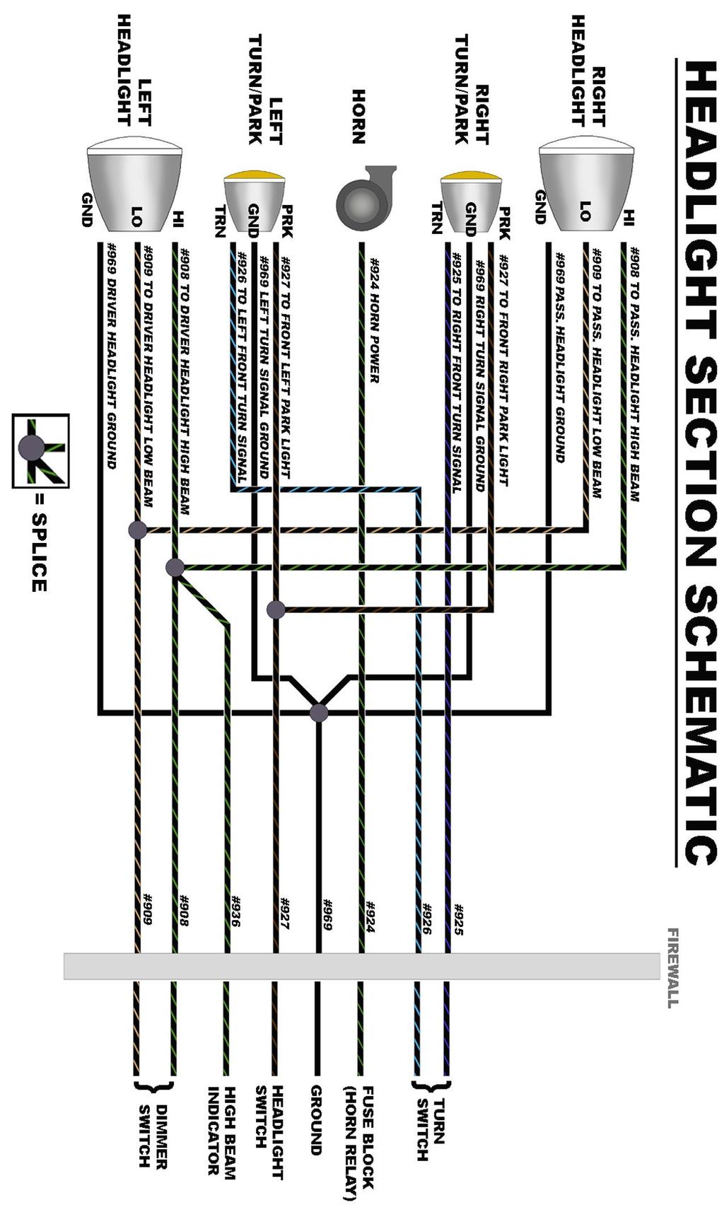
24 HEADLIGHT SECTION CONNECTIONS The HEADLIGHT SECTION of this Painless Harness includes all power and ground wires needed to properly hook up both driver and passenger side headlights, and left and right front turn & park/marker lights. There is also a power wire from the fuse block mounted horn relay to power a horn. All wires in the Headlight Section can be seen in the Headlight Section Schematic on page 30. Left/Driver Side Headlamp Your first connection in the Headlight Section will be the Left/Driver side Headlamp. Three wires make up the connection to the Left Headlamp, they are: Black/Green: 14 gauge wire, printed [HEADLIGHT SECTION] #908 TO DRIVER HEADLIGHT HIGH BEAM, this wire will provide power to the high beam filament of the head lamp. This wire goes into a splice with a wire going to the right headlamp and also to a wire going to the high beam indicator in the dash and to the dimmer switch. This wire will have power when the dimmer switch is in the high beam position and the headlight switch is in the headlight ON position. Black/Tan: 14 gauge wire, printed [HEADLIGHT SECTION] #909 TO DRIVER HEADLIGHT LOW BEAM, this wire will provide power to the low beam filament of the head lamp. This wire goes into a splice with a wire going to the right headlamp and also to a wire going to the dimmer switch. This wire will have power when the dimmer switch is in the low beam position and the headlight switch is in the headlight ON position. Black: 14 gauge wire, printed [HEADLIGHT SECTION] #969 DRIVER HEADLIGHT GROUND, this wire provides a ground source for the headlamp. This wire is tied into the integrated ground circuit and can be seen in the Ground Schematic on page


25 The connection of these three wires will depend on the style headlights you are using in your application 3 prong, Sealed Beam/ Sealed Beam Halogen/ H4 halogen Connectors and terminals have been provided in the parts kit to allow proper connection to these 3 prong headlights. Locate the terminals and connector seen in the photo below. Please be aware these terminals look just like smaller narrower terminals provided in the kit; you will need the larger terminals for this connection. These terminals will be in the same compartment as the connectors. Route the 3 wires for left/driver side headlamp connection to the back of the headlamp. Removing the headlamp may be necessary and is recommended to ensure the terminals of the headlamp are not damaged during connection; they are easily bent if the connector is not installed correctly. Cut the 3 wires to length and strip ¼ of insulation from all 3 wires. Using a set of roll over crimpers, as shown on page 11, crimp a terminal onto each wire. Insert all three wires in the connector according to photo above. 25


26 Plug the connector onto the prongs of the headlamp. Make sure the connector is inserted straight onto the prongs as these prongs will easily bend making a proper connection difficult. If halogen bulbs are being used Painless recommends using Painless part # This headlight relay kit is needed to avoid overloading the headlight switch with the higher demands of halogen bulbs. Headlights with Pigtails In order to make the appropriate connections consult the manufactures instructions of the headlights you are using to identify each wires function. If you do not have instructions, or know the manufacturer of the lights on your vehicle, you can test a light using your vehicles battery. On units that have 3 wires, in almost all cases there will be a black wire, this is typically a ground, while the other two colored wires are obviously the power for the high and low beams. Units with 5 or 6 wires also have turn/park light features. Touch one of the colored wires to the positive side of the battery. With the colored wire touching the positive side, now touch the black wire, or both black wires if your lamp also has turn/park, to the negative side. You may see a couple sparks upon connecting to the negative side but this is normal. The light should now be on, take notice to how bright the light is. Remove both wires from the battery and repeat this process with the other colored wire(s). First to the positive side, and then the ground(s) to the negative side. Whichever wire on the positive side on the battery made the light(s) brighter is the high beam power wire or turn signal if your lamps have this option. Write this down in the notes section at the back of this manual for future reference. In some cases headlamps will have a Green, Brown or Tan, and Black wire coming from them, like shown in the photo above. This is a common GM style color code meaning: Black = ground, Brown or Tan= low beam, Green= high beam. Connection of the #908, #909, & #969 wires of the Painless harness will be made using the nickel plated splices provided in the parts kit along with pieces of heat shrink. 26

27 Each wire, coming from the headlight bucket as well as the Painless Harness will be cut to length and have ¼ of insulation stripped from them. Connect the splice to each of the 3 wires on the Painless harness, taking the split on the splice into consideration as shown on page 8. With the splice crimped, slide a piece of heat shrink onto each wire. Insert the wires from the headlight bucket into the splice that corresponds with the wires function: High Beam wire to the Painless Black/Green wire printed #908 Low Beam wire to the Painless Black/Tan wire printed #909 Ground wire to the Painless Black wire printed #969 With the wires now crimped, slide the heat shrink over the splice and apply heat with a heat gun* to shrink it down and make a weather resistant connection. *Some may opt to use a small soldering torch or even a cigarette lighter to accomplish this. This is not advised as it tends to overheat the heat shrink causing it to bubble or crack. Use caution to prevent overheating if using any kind of flame. NOTES: 27
![Left Turn/Park Light The Left Turn/Park Light of the Painless harness consists of 3 wires, These wires are: Black/Brown: 18 gauge wire, printed [HEADLIGHT SECTION] #927 TO FRONT LEFT PARK LIGHT, is](/docs-images/90/103923551/images/28-0.jpg "the power source for the park light. This wire is spliced to the other #927 wire in the Head Light Section and also with a #927 wire going to the Headlight Switch.")
28 Left Turn/Park Light The Left Turn/Park Light of the Painless harness consists of 3 wires, These wires are: Black/Brown: 18 gauge wire, printed [HEADLIGHT SECTION] #927 TO FRONT LEFT PARK LIGHT, is the power source for the park light. This wire is spliced to the other #927 wire in the Head Light Section and also with a #927 wire going to the Headlight Switch. This wire will have power anytime the headlight switch is in the Park/Tail Lights ON or Headlights ON position. Black/Light Blue: 18 gauge wire, printed [HEADLIGHT SECTION] #926 TO LEFT FRONT TURN SIGNAL, this wire is the turn signal power. This wire goes into a splice with the Black/Light Blue wires going to the left turn indicator light and to the wire coming from the turn signal switch. This wire will have interrupted switched power from the turn signal flasher any time the left turn signal is activated and the ignition is in the ON position and interrupted battery power from the hazard flasher any time the hazard switch is in the ON position. Black: 18 gauge wire, printed [HEADLIGHT SECTION] #969 LEFT TURN SIGNAL GROUND, this wire provides a ground source for the turn/park lamp. This wire is tied into the integrated ground circuit and can be seen in the Ground Schematic on page 14. If your light has a dual filament bulb and only 2 wires, you will not connect the black #969 wire. Your light socket grounds though the mounting of the lens/bucket. If this is the case, #969 can be removed from the harness or connected to the frame or any other clean ground source. If your light has a single filament bulb, your lens will only act as a turn signal. #927 will not have a connection point; check your local laws to see if front park lights are required, you could be in violation of the law without them. If you can run without the front park lights, both #927 wires, along with the other wire going to the headlight switch splice to these can be removed from the Painless harness The #926, #927, & #926 will be connected to the wires coming from the Turn /Park light with splices and heat shrink. If you are unsure of which wires is the park light and turn signal, follow the instructions given on page 25 for testing the function of each wire. The brighter of the two functions (park and turn signal) will be the turn signal function. If your lens or bucket only has 2 wires and is a dual filament bulb, the testing will have to be done with the lens/ bucket mounted to the vehicle for proper grounding. NOTES 28


29 Horn The Headlight Section has a single wire dedicated for connection to a horn. *Most horns ground through their mounting and only require a power connection. This wire is: Black/Green: 16 gauge wire, printed [HEADLIGHT SECTION] #924 HORN POWER, this is a power wire that comes from the fuse block mounted horn relay which is ground activated by the horn button on the steering column. This wire will only have power when the horn button is pressed. Route the #924 wire to the horn. If you have to pass this wire through any metal surfaces, you will find small grommets in the parts kit to protect the wire. If you have a tab on the horn, locate the terminal and connector, seen to the right, provided in the parts kit. Ring terminals and heat shrink have been provided for those with screw or post & nut connections. If your horn has a wire to connect to, then a splice and heat shrink will be needed. *If your horn requires a ground wire, use a piece of scrap wire that was cut from the any of the black #969 ground wires on the driver side headlight or turn/park light connections to connect the ground on the horn. Using a ring terminal from the parts kit, attach the other end of the ground wire to a chassis ground source on the vehicle. Right Turn/Park Light & Right Headlamp The connections mentioned above all connect in the same manner as those on the left/driver side. The only difference you will find is the Turn signal wire for the right turn signal has a different color stripe that one used for the left turn signal. The right Turn signal will be: Black/ Blue: 18 gauge wire, printed [HEADLIGHT SECTION] #925 TO RIGHT FRONT TURN SIGNAL, this wire is the turn signal power. This wire goes into a splice with the Black/ Blue wires going to the right turn indicator light and to the wire coming from the turn signal switch. This wire will have interrupted switched power from the turn signal flasher any time the left turn signal is activated and the ignition is in the ON position and interrupted battery power from the hazard flasher any time the hazard switch is in the ON position. This concludes all of the connections in the Headlight Section of the engine harness. Go back and inspect the harness layout and once satisfied it is free of moving parts and sharp edges tighten any loose zip ties. 29
30 30


31 Engine/Ignition Section The Engine Section consists of five wires for connections to oil pressure and coolant temperature sending units for the gauges, connections to the coil or ignition system, and a connection for an electric choke on a carburetor. Locations of all of these components will vary from vehicle to vehicle so no specific routing instructions can be given. All wires of the Engine Section will have ample length to account for the numerous way components can be mounted inside an engine compartment. For example: an Ignition box mounted on the inner fender will require more length of wire than if power was going to a firewall mounted coil. Coil / Ignition Power to the coil / ignition system is supplied with a single wire coming from the fuse block. The connection of this wire will vary depending on what ignition system, factory or aftermarket, you use. The wire needed to supply a switched ignition power source is: Black/Pink: 16 gauge wire, printed [ENGINE SECTION] #920 TO COIL + (IGN. POWER) this wire comes from the 30 amp COIL fuse. This wire will have power anytime the ignition switch is in the on and start positions. This wire will provide the Coil / ignition system with switched power in one of four ways: If the Coil you are using is not internally resisted, a ballast resistor along with the Black/Yellow wire mentioned in the next step, must be used. A ballast resistor, provided in the kit and seen to the right, resists the current going to the coil. If a coil is not internally resisted and a ballast resistor is not used, the coil will overheat within a few minutes to the point it will no longer work. See the Ballast Resistor Connection Diagram on p

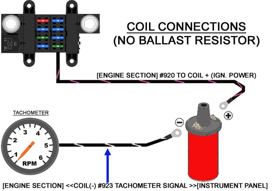
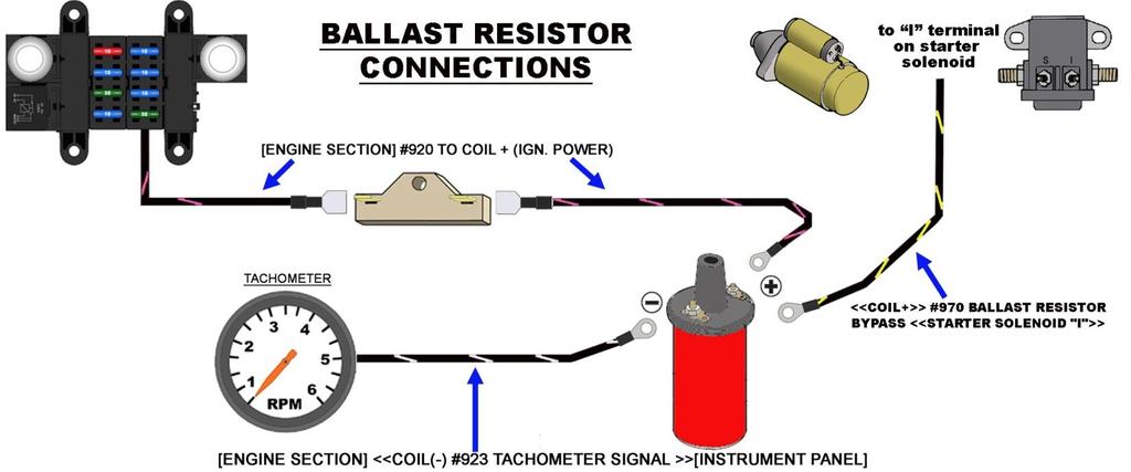
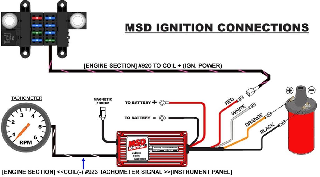
32 HEI coils, internally resisted coils, and most aftermarket ignition boxes do not require the use of a ballast resistor. The #920 wire will connect directly to the + side of the coil. See the NO Ballast Resistor Connection Diagram on page 34. If an aftermarket Ignition box is being used, such as an MSD, Accel, etc., this Black/Pink #920 wire will supply the Ignition box with the switched power source it requires. This wire will go to the aftermarket ignition box and not the Coil; the Ignition Box will provide the Coil + connection. This #920 wire may need to be pulled from the Engine Section and routed to where the box is mounted. See the Ignition box manufacturer s instructions for a specific connection point of this power source. MSD Ignition Connection on page 34 has been provided. If you have converted to fuel injection and are using a standalone harness, such as any of Painless fuel injection harness, and coil power is supplied though the fuel injection harness, in LT1/LS1 and newer applications, this Pink/Black wire will provide the fuel injection harness with the switched power source the harness requires. If using a Painless fuel injection harness, this Black/Pink #920 wire will connect to the open ended Pink wire of the fuel injection harness labeled IGN or Fuse Block IGN. Route this Pink/Black #920 wire to its proper connection point and cut to length, install the appropriate terminal for your connection, and connect. Terminals and a factory style connector, seen in the photo at right, have been supplied to allow connecting to the + side of a HEI Coil. An added bonus of the coil fuse is it also provides a built in theft deterrent. Removing the COIL fuse from the fuse block when the car is parked for periods of time will not allow the ignition system to function, making the vehicle virtually impossible to start/run. What would be thief is going to trouble shoot power to the coil? Ballast Bypass Locate the individually rolled 16 gauge Black/Yellow wire printed <<COIL+>> #970 BALLAST RESISTOR BYPASS <<STARTER SOLENOID "I">>. This wire will not be part of either of the harnesses provided, but a completely separate roll of wire. This wire will only be needed if you are using a ballast resistor. Most installs will not need this wire and can be omitted from the install. On vehicles utilizing a ballast resistor, this wire is intended to connect to the positive side of the coil from the I terminal of the starter solenoid and will provide the coil full 12v of power when the starter solenoid is engaged by bypassing the ballast resistor and going directly to the coil. This is done to facilitate starting the engine and will not harm the coil. If connected to the starter solenoid correctly, as indicated on page??, this wire will only have power when the ignition switch is in the START or crank position. 32

33 Tachometer Route the Black/ Yellow #970 wire to the + side of the Coil or to the output side of the Ballast resistor. The Ballast Resistor Connection Diagram on the next page has been created to aid in this connection. The other end of this #970 wire will route to the I terminal on the starter solenoid. Connection will be covered later in the manual on page 54. Locate the 18 gauge Black/White wire printed [ENGINE SECTION] <<COIL(-) #923 TACHOMETER SIGNAL >>[INSTRUMENT PANEL]This wire will send tachometer signal from the coil to the gauge cluster. This wire will only be connected if you are using a tachometer (factory or aftermarket). If you do not have a tachometer, this wire may be removed from the harness. Depending on your ignition system (factory or aftermarket) or use of fuel injection, the connection of this #923 wire can vary: Standard factory type of installs with a HEI distributor or external coil ignition systems, will require this #923 wire to be connected to the negative - side of the coil. Refer to the diagrams on the next page for proper connection. Terminals and a factory style connector have been supplied to allow connecting to the - side of a HEI Coil, seen in the photo at right, rollover crimpers will be needed to properly install this terminal. Insulated terminals in the parts kit have been supplied to make other connections. If you are running fuel injection and your ECM has a tach output wire, and the tach output wire of the fuel injection harness will not reach the tachometer, this #923 wire will connect to the tach output wire from the ECM. If an aftermarket ignition box is being used, such as an MSD, Accel, etc., this #923 wire will connect to the tach output found on the ignition box. Refer to the MSD Ignition Connection on the next page and to the ignition manufacturer s installation procedure. Route this Black/White #923 tach signal wire to its proper connection point and cut to length, install the appropriate terminal for your connection, and connect. Use one of the following four diagrams to properly connect the coil power (#920), tachometer (#923), and ballast bypass (#970). Not shown in the diagrams are the wire(s) connecting the coil and the distributor, these are not included. 33
34 34


35 Engine Sending Units/Switches The engine should have two gauge sending units: coolant temp and a oil pressure. If you are using aftermarket mechanical gauges, then no connections will need to be made. You can skip to the next connection, Electric Choke on page 37. Sending units operate based on resistance to ground. Meaning the cooler the engine or less oil pressure seen, the more ground (less resistance) these sending units will provide to the wire connected to them. As the ground resistance strengthens as the temps and/or pressure builds, less ground is applied to the gauge. As the ground signal weakens, the needle on the gauge moves to read higher temps and/or higher oil pressure. If you left these wires unconnected or have a bad ground between the sending unit and engine/intake manifold, the gauges would peg to their highest reading. Coolant Temp Locate the 18 gauge Black/Green wire printed [ENGINE SECTION]<<TO TEMP SENDER #921 TO TEMP GAUGE>> [INSTRUMENT PANEL]. This wire will send a ground signal to the engine coolant temp gauge. If you are using an aftermarket mechanical gauge, this wire will not be used. The coolant temp sending unit/switch can be mounted in the intake manifold or in the side of either cylinder head. These will have a peg, tab or threaded post to connect to like seen in the photo above. Two wire temperature sensors on fuel injected engines are for engine computer input, not for gauge signal. Also, if connecting to an engine in a vehicle that has electric cooling fans, make certain you know the difference between the coolant temp sensor and the electric fan thermostatic switch; both of these sensors can look identical. 35


36 If you are installing a new temp sensor, or are unsure of the temp sensor currently mounted in your engine, make sure there is no tape on the sensor threads. The tape will interfere with the ground source the sensor needs to read correctly. Liquid/tube sealant can be used. Route this Black/Green #921 wire to the coolant temp sensor, cut to length, install the appropriate terminal for your connection, and connect. Terminals and a factory style connector, seen in the photo below, have been supplied to allow connecting to a factory style sensor, rollover crimpers will be needed to properly install this terminal. NOTES 36
![Oil Pressure Locate the 18 gauge Black/Lt.Blue wire printed [ENGINE SECTION A] << TO OIL SENDER #922 TO OIL GAUGE>> [INSTRUMENT PANEL SECTION].](/docs-images/90/103923551/images/37-0.jpg "Do not get this confused with the Black/Blue wire for the choke function.")


37 Oil Pressure Locate the 18 gauge Black/Lt.Blue wire printed [ENGINE SECTION A] << TO OIL SENDER #922 TO OIL GAUGE>> [INSTRUMENT PANEL SECTION]. Do not get this confused with the Black/Blue wire for the choke function. The #922 wire will send a ground signal from the sending unit/switch through the bulkhead into the interior of the vehicle to the gauge cluster and to the aftermarket gauge connector. If you are using a mechanical pressure gauge, this wire will not be needed. The oil pressure sending unit will generally be located near the oil filter or on the back of the block behind the intake manifold. Route this Black/Blue #922 wire to the oil pressure sending unit, install the appropriate terminal for your connection, and connect. Terminals and a factory style connector, seen in the photo to the right, have been supplied to allow connecting to a stud style sensor like the one shown above. Rollover crimpers will be needed to properly install this terminal. If you have a 2 wire sensor on a newer fuel injected donor engine it will not work for your pressure gauge. 2 wire sensors on fuel injected engines are for fuel pump control and are not designed for oil pressure gauge readings. These types of sensors are generally found on GM TBI and TPI engines. Electric Choke Locate the 18 gauge Black/Blue wire printed [ENGINE SECTION] #954 TO ELECTRIC CHOKE. This wire will provide a switched ignition power source to the choke from the 10 amp CHOKE fuse. This wire will have power when the ignition switch is in the ON/RUN position. When you turn your key to the ON/RUN position, the voltage this wire carries will heat the bi-metal spring attached to the shaft of the choke. This spring will unravel as it is heated causing the choke to slowly open. When the ignition is turned to the OFF position, power is no longer on this wire, causing the spring to begin to cool and contract, closing the choke. 37


38 If you do not have an electric choke, this wire will not be needed and can be removed from the harness. Route this Blue #954 wire to the + terminal of the electric choke, install the appropriate terminal for your connection, and connect. Ensure the choke is properly grounded, ground wire not supplied in the Painless harness, before continuing with the installation. The following schematic shows the Engine Section wiring on a common chevy V8 not using a ballast resistor. 38


39 START/CHARGE Section The Start/Charge Section consists of five wires for connections to the alternator, starter solenoid, and in line MIDI fuse (included with the kit). Locations of all of these components will vary from vehicle to vehicle so no specific routing instructions can be given. Locate the bag kit provided with the Painless harness labeled ALTERNATOR. This bag kit will contain hardware needed to make the appropriate connections to the alternator as well as contain a covered inline fuse holder. Alternator The alternator connections will vary depending on the alternator your vehicle currently has installed. The alternator may also need to be removed in order to gain access to the connection points. The one connection all alternators will have in common is the output post. This will send amperage from the alternator to the battery. This connection will be made using the large gauge red wire rolled in the kit, it is: Red: 6 gauge wire, with a label printed #915 ALTERNATOR OUTPUT, this wire will provide power out of the alternator to the battery through the MAXI fuse. This wire will have power at all times and comes from the large battery supply splice in the harness. See Charge/Battery Power Schematic on page 53. Locate the rubber alternator boot and a large un-insulated ring terminal from the ALTERNATOR bag that has the right size opening for your alternator post. The piece of red heat shrink may be used along with the boot or just by itself over the terminal crimp if the alternator boot is not desired. A piece of wire loom is also provided with this kit to cover the #915 charge wire after installation to help keep with the all black theme of this harness. The charge wire is not a black wire to help keep it from being confused with a negative/ground cable. If the rubber boot is being used, the end will need to be cut as shown in the photo below to allow the large gauge wire to pass through. 39

40 If the heat shrink is being used, slide it onto the #915 wire, followed by the rubber boot. A very small amount of lubricant such as WD-40 or motor oil may be applied on the inside of the rubber boot to allow the boot to slide down the wire easier. With the boot on, strip about ¼ of insulation from the charge wire and crimp the ring terminal on. You can use a pair of pliers if your crimpers will not accept this large gauge wire/terminal. Connect this wire to the B+/Output stud on the Alternator. Once the nut is on the stud on the output post has been tightened, the boot can now be slid up the wire to cover the nut and ring terminal installed on the Alternator. The heat shrink can be slid over the end of the boot and shrunk down. Be advised this heat shrink will have to be removed before the rubber boot can slide back down the wire if the charge wire is ever to be removed. If your vehicle has an aftermarket ONE WIRE ALTERNATOR, meaning it does not require a switched 12v souce or regulator connections or if the Painless or other aftermarket fuel injection harness you are using has an alternator connector, then this output wire is the only wire used in this section at the alternator. A one wire GM 10-SI can be seen below. Locate the 2 wires intended for alternator regulator connections; they will be grouped together in the Start/Charge Section. These wires are: Black/Red: 14 gauge wire, printed [START/CHARGE] #995 REGULATOR BATTERY POWER, this wire will provide a battery power source, or amperage sample that some voltage regulators require. This wire will have power at all times and comes from the large battery supply splice in the harness. This wire will not be needed if you have a one wire alternator or a GM CS series alternator. See Charge/Battery Power Schematic on page
![Black/Brown: 16 gauge brown wire, printed [START/CHARGE] #914 TO ALTERNATOR REGULATOR EXCITER, this wire can have switched ignition power from the fuse block.](/docs-images/90/103923551/images/41-0.jpg "This wire will not be needed if you have a one wire alternator.")

41 Black/Brown: 16 gauge brown wire, printed [START/CHARGE] #914 TO ALTERNATOR REGULATOR EXCITER, this wire can have switched ignition power from the fuse block. This wire will not be needed if you have a one wire alternator. If you have a one wire alternator, and only if you have a one wire alternator, you will need to insulate the ends of these wires and stow them in the harness, THEY ARE POWER WIRES. These two remaining wires, black/red wire printed #995 and a black/brown wire labeled #914, can be removed from the harness. #995 may also be connected to the output post of the alternator to avoid removing it from the harness since this wire goes into the big battery power splice. If you do not want to remove them, install insulted terminals to the end of each wire and tape up into the harness. Charge Indicator light Those wanting to add a charge indicator light will need to re-route the Black/White #914 wire found in the START CHARGE section of wires. This wire will then be connected to the light and then out the other side of the light to the alternator voltage regulator. The way the light will function is: Switched 12v voltage will come into one side of the light, pass through the light, and out to the voltage regulator for the alternator. Voltage moving through the filament will cause the light to illuminate. This light will illuminate when the key is in the ON/RUN position and the alternator is not charging because the engine is not running or the alternator is not working properly. Once the alternator is charging the voltage regulator no longer needs the voltage supplied by the charge wire, which stops the flow. Since power is no longer flowing through the filament, the bulb does not illuminate. If you are using a one wire alternator, a charge light cannot be installed since you do not have an alternator exciter wire going to the regulator. Connect a wire for power into the light, wire #914 ALTERNATOR EXCITER, the remainder of #914 will connect to the other side of the light to provide power out to the voltage regulator. See the diagram below. It is also recommended, but not necessary, to wire in a 15 ohm 2 watt resistor between the power in and power out, seen in the diagram above. This will provide enough power to the voltage regulator to allow the alternator to still charge in the event the bulb burns out. This resistor can be found through online electronic component suppliers such as Mouser or Allied Electronics under part # OY150KE, or RadioShack # NTE 2W


42 The remaining alternator connections will vary based on which alternator is being used. Choose the alternator that best represents the alternator found on your vehicle from the on the next few pages and follow the instructions provided for your particular alternator. NOTES General Motors SI Series Alternators The 10-SI and 12-SI alternators are easy to identify. They will have an external fan behind the pulley, the 12-SI having enclosed style fan blades, and a two pin connection. This 2 pin connection can be seen on the middle image in the diagram above. These are also known as Delco or Delcotron alternators. The two remaining wires, a 14 gauge black/red wire printed #995 REGULATOR BATTERY POWER and a 16 gauge black/brown wire labeled #914 ALTERNATOR EXCITER, will connect to the two posts on the back edge of the alternator. Route the two wires to the numbered 1 & 2 terminals on the alternator and cut to length. Strip ¼ of insulation from both wires. A factory style connector and terminals, seen in the photo, have been provided in the ALTERNATOR bag. Crimp a terminal onto each of the two wires. Insert the wires into the connector as shown in the diagram on the next page. When terminal pin-out is complete, plug the connector into the alternator. 42


43 You may experience engine run on. This is caused when the alternator back feeds voltage down the #914 wire after the key has been turned off. This allows the ignition system to still function causing the engine to continue running even though the key is turned off or even removed from the ignition. If this should happen unplug the alternator connector to shut the engine off. If you experience this, a remedy has been provided. As shown in the photo on the previous page and diagram below, a diode, splices and heat shrink have been provided. If engine run on occurs, simply install the diode as shown. When the diode is installed inline of the #914 wire with the stripe towards the alternator, the diode will let voltage flow towards the alternator, but not away from the alternator towards the ignition system, thus fixing the back feed/ run on issue. General Motors CS-130 Series Alternators The CS-130, CS-121 and CS-144 alternators closely resemble the SI series alternators. They will have an external fan behind the pulley and they generally have some plastic casing on the side and back. These alternators have a four pin sealed connector, seen in the photo below and in the middle image above. The regulator will be marked P,L,S,F. This type of alternator was used on GM TPI and LT1 fuel injected engines among other late 1980 s to mid 1990 s GM vehicles. The two remaining wires, a 14 gauge black/red wire printed #995 REGULATOR BATTERY POWER and a 16 gauge black/brown wire labeled #914 ALTERNATOR EXCITER, will connect to the regulator on the back of the alternator. 43
, will need to be used.")


44 Route the two wires to the connector on the alternator and cut to length. Strip ¼ of insulation from both wires. The factory 4 pin alternator connector from a factory GM harness or a CS-130 pigtail purchased from Painless, part # (see photo), will need to be used. Due to a lack of usage by most customers it is not included with this Painless chassis harness. The CS-130 alternator requires a resistance on the #914 wire. Without this resistance the regulator on the alternator will burn up. A resistor, splices, and heat shrink, seen below, have been provided in the ALTERNATOR bag kit. The resistor* will simply need to be installed inline on the #914 wire as shown in the diagram on the next page. *In factory applications where this alternator was used this resistance was created through a charge indicator light. For those with an instrument panel with a charge indicator light, the resistor will not be needed. However the #914 wire will need to be routed to one side of the charge indicator light and the other side of the light will then route out to the alternator. A charge indicator light was further explained on page 41. Using two of the splices and heat shrink provided in the ALTERNATOR bag kit, splice the CS-130 pigtail to the #914 and #995 wires according to the diagram below. 44


45 General Motors CS-130D Series Alternators The CS-130D can be spotted by the lack of an external fan behind the pulley. These alternators have an internal fan. They also have a plastic casing on the back. These alternators have an elongated oval, four pin sealed connector, seen in the photo on the next page and in the image above. The regulator will be marked P,L,I,S. This type of alternator was used on many engines, including the GM LS series, Vortec and Gen. III Vortec truck fuel injected engines. Of the two remaining wires, a 14 gauge black/red wire printed #995 REGULATOR BATTERY POWER and a 16 gauge black/brown wire labeled #914 ALTERNATOR EXCITER, only the #914 will be used. The #995 may be connected to the alternator output post or removed from the harness. Route the black/brown #914 to the connector on the alternator and cut to length. Strip ¼ of insulation. The factory 4 pin alternator connector from a factory GM harness or a CS-130D pigtail purchased from Painless, part # (see photo), will need to be used. The CS-130D alternator requires a switched power source to pin I of the regulator, and a resisted power source on the wire going to pin L of the regulator. Without this resistance the regulator on the alternator will burn up. A resistor, splices, and heat shrink, seen on the previous page, have been provided in the ALTERNATOR bag kit. The resistor will simply need to be installed inline on the L pin wire as shown in the diagrams on the next page. Using a splice and heat shrink provided in the ALTERNATOR bag kit, splice the CS-130D pigtail to the black/brown #914 wire according to one of the diagrams on the next page. 45

46 Both diagrams accomplish the same task, using the black/brown #914 ALTERNATOR EXCITER wire to provide a switched power source and a resisted power source to the 2 wires of a CS-130D alternator pigtail/connector when a charge indicator light is NOT being used. Pick the method that easiest for you to understand. 46

47 General Motors Externally Regulated Alternators The two remaining wires, a 14 gauge black/red wire printed #995 REGULATOR BATTERY POWER and a 16 gauge black/brown wire labeled #914 ALTERNATOR EXCITER, will connect to the regulator. Route the two wires of the Painless harness to the connection point on the regulator and cut to length. Strip ¼ of insulation from both wires. The factory 2 pin alternator connector and 4 pin regulator connector from a factory GM harness can need to be used. Due to a lack of usage by most customers these connectors are not included with this Painless chassis harness. If you do not have these connectors, they can be obtained online, at a local auto parts store, or you can use the loose piece insulated terminals in the parts kit to make connections. Connect the black/brown #914 wire to the 4 terminal on the regulator. Connect the red/black/#995 to the 3 terminal on the regulator. Two 14 gauge wires which run from the regulator to the alternator and a 14 gauge wire for a ground will need to be provided by the installer to finish the connections. These wires are not in the Painless harness. Connect the 2 terminal on the regulator to the R terminal on the alternator. This was a white wire from the factory. Connect the F terminal on the regulator to the F terminal on the alternator. This was a blue wire from the factory. The last connection will be connecting a wire from the G post on the alternator to a chassis ground source. 47
48 Ford Externally Regulated Alternators The two remaining wires, a 14 gauge black/red wire printed #995 REGULATOR BATTERY POWER and a 16 gauge black/brown wire labeled #914 ALTERNATOR EXCITER, will connect to the regulator. Route the two wires of the Painless harness to the connection point on the regulator and cut to length. Strip ¼ of insulation from both wires. The factory 4 pin alternator connector from a factory harness will need to be used. Due to a lack of usage by most customers these connectors are not included with this Painless chassis harness. If you do not have these connectors they can be obtained online, at a local auto parts store, or you can use the loose piece insulated terminals in the parts kit to make connections. Connect the black/red #995 to the A terminal on the regulator. Connect the black/brown #914 wire to either the I terminal on the regulator or to the S terminal. The two diagrams provided on the next page show two different ways to power the regulator. The difference in the diagrams is where the #914 wire connects, which in turn, will decide how many wires run from the regulator to the alternator. See the diagrams on the next page. Please be advised that a charge indicator light will only work if the regulator is wired according to Method 1. Depending on how the #914 wire was connected, one or two 14 gauge wires which run from the regulator to the alternator and a 14 gauge wire for a ground will need to be provided by the installer to finish the connections. These wires are not in the Painless harness. If the #914 was connected to the I terminal on the regulator. Connect the S terminal on the regulator to the S or stator post on the alternator. If the #914 is on the S terminal of the regulator, S or stator post on the alternator will not be connected. Connect the F terminal on the regulator to the F terminal on the alternator. The last connection will be connecting a wire from the G post on the alternator to a chassis ground source. 48

, this kit contains the connectors terminals and large in line")
49 Ford Internally Regulated Alternators (3G) In order to make the correct connections to a 3G ALTERNATOR, 2 connector pigtails for the alternator will be needed. These pigtails can be bought in numerous places under the Motorcraft part numbers WPT-119 and WPT-851. The installer will also need to supply an inline fuse with a rating of 125 amps or more. Painless offers a complete 3G connection kit, part # (see photo), this kit contains the connectors terminals and large in line fuse to support all connections required by this alternator. 49

50 The two remaining wires, a 14 gauge black/red wire printed #995 REGULATOR BATTERY POWER and a 16 gauge black/brown wire labeled #914 ALTERNATOR EXCITER, will connect to the pigatils on the back of the alternator. Connect the two alternator pigtails to the alternator. Route the black/brown #914 wire and the black/red #915 wire to the 2 wires coming from the 3 wire connector pigtail, and cut to length and strip ¼ of insulation. The 3G alternator requires a switched power source to pin I of the regulator, this will be the #914 wire. Using a splice and heat shrink provided in the ALTERNATOR bag kit, splice the pigtail to the black/brown #914 wire according to the diagram below. The 3G alternator requires a constant battery power source to pin A of the regulator, this will be the #995 wire. Using a splice and heat shrink provided in the ALTERNATOR bag kit, splice the pigtail to the black/red #995 wire according to the diagram below. The 2G, and 4G alternators wire up in the same manner as the 3G in regards to the I and A terminals on the regulator. 50

51 MOPAR Externally Regulated Alternators There are two types of external regulators found on these charging systems: mechanical and electrical. The mechanical regulators, pre-1970, will have two posts marked IGN and FLD. One post will exit one side of the regulator, while the other post will exit the other side. This regulator will use an alternator that has a single field terminal, as shown in the PRE-1970 diagram below. The electrical regulators, 1970+, will also have two posts marked IGN and FLD, but both posts will be found on top of the regulator and will require a connector. This regulator will use an alternator that has two field terminals, as shown in the diagram below. Of the two remaining wires, a 14 gauge black/red wire printed #995 REGULATOR BATTERY POWER and a 16 gauge black/brown wire labeled #914 ALTERNATOR EXCITER, only the #914 will be used. The #995 may be connected to the alternator output post or removed from the harness. Route the #914 wire of the Painless harness to the connection point on the regulator and cut to length. Strip ¼ of insulation from the wire. Connect the black/brown #914 wire to the IGN terminal on the regulator. Take notice that on the electronic regulator, this #914 wire will splice into the wire between the IGN terminal on the regulator and one of the field tabs on the alternator. If using an electronic regulator, the two pin connector from a factory harness will need to be re-used. Due to a lack of usage by most customers these connectors are not included with this Painless chassis harness. If you do not have these connectors they can be obtained online or at a local auto parts store. 51

52 14 gauge wire(s) which run from the regulator to the field terminal(s) on the alternator will need to be provided by the installer to finish the connections. These wires are not in the Painless harness. MIDI Fuse Connect the FLD terminal on the regulator to the FLD terminal on the alternator. A large in line MIDI fuse has been included in the Alternator bag kit. This inline fuse will provide a fused link between the alternator and battery. Find a suitable location to mount the supplied fuse holder using the 2 screws provided. A drill with a 3/32 or.100 bit will be required in order to drill holes for the mounting screws. With the holes drilled, mount the fuse holder. With the fuse holder now mounted locate the following two wires: Black/Red: 10 gauge wire, printed [START/CHARGE] #916 TO BATTERY SOURCE All power sources in this Painless harness originate from this wire. This wire provides battery power to the fuse block, which in turn supplies battery power to the ignition switch which provides switched power. During normal operation, this wire will have constant battery power at all times. Red: 6 gauge wire, with a label printed #915 ALTERNATOR OUTPUT, this wire provides power out of the alternator to the battery through the MIDI fuse. This wire will have power at all times and comes from the large battery supply splice in the harness. See Battery Power Schematic on the next page. The other end of this wire was connected to the output post of the alternator. Route the #916 and #915 wires to one side of the fuse holder and cut the wires to length. Those using a MOPAR starter relay, please see page 56 before cutting #916. DO NOT DISCARD THE CUT OFF PORTION OF #915. The length of excess wire cut from the #915 wire will be used to connect the other side of the fuse to the + side of the vehicle s battery or to the battery post on the starter solenoid. DO NOT CONNECT THE #915 TO THE ACTUAL BATTERY AT THIS TIME. If routed to the starter solenoid, this wire will NOT replace the battery cable needed by the starter from the positive side of the battery to the BAT or + post of the starter solenoid. Connection to both sides of the fuse holder will be made using the large ring terminals with the small #10 hole provided with the kit. You can use a pair of pliers if your crimpers will not accept this large gauge wire/terminal. The heat shrink supplied with this kit is intended to cover the crimped end of each of these two ring terminals. A schematic showing these connections can be found on the next page. 52

53 Once the ring terminals are installed onto both studs of the fuse holder the fuse can be installed and everything can be tightened down with the two retaining nuts provided with the fuse holder. Once everything is tightened, the cover can be reinstalled. Depending on how your crimp flares the ring terminal, the cover may or may not need slight trimming in order to snap into place. NOTES: 53
54 Starter The connections to the starter will vary depending on your ignition system, the location of a neutral safety/clutch switch, and your connection point on the battery power source for the MIDI fuse. You will find 2 wires grouped together for starter connections. These wires are: Black/Purple: 12 gauge wire, printed #919 STARTER SOLENOID "S" (START SIGNAL), this wire will supply the solenoid with a switched power source from the ignition switch. This power will activate the starter solenoid causing it to turn the engine over for start up. This wire will only have power when the ignition switch is in the Start/Crank position. Black/Yellow: 16 gauge wire printed #970 IGNITION BYPASS (COIL "+" TO STARTER "I"). This wire will provide the coil a full 12v of power when the starter solenoid is engaged this wire will only have power when the key is in the Start/Crank position. Only installs using a ballast resistor will require the use of this wire. The installs that utilize an internally resisted coil, an HEI distributor, or an aftermarket electronic ignition will not need to connect this wire; it may be removed from the harness. Route the black/purple #919: If you are using a transmission mounted neutral safety switch (MOPAR reverse switch/nss excluded) or an engine bay column mounted NSS: #919 will route to the neutral safety switch. Cut to length and route the remainder of #919 from the neutral safety switch to the starter solenoid or to the starter relay. Connection of the NSS will be handled on page 56. If you have a column or shifter mounted neutral safety switch (like the GM switch shown on page 93 of the second manual), clutch switch, or MOPAR transmission mounted reverse/nss switch: #919 will route to the Starter solenoid or starter relay. Connection of the NSS will be handled on page 79. Route the black/yellow #970 (if used), to the starter solenoid or starter relay and cut to length. Be sure to keep all wires away from the exhaust manifold or header. If you are connecting the battery supply to the MIDI fuse to the battery cable/post on the Starter, connect it now. BE SURE THE BATTERY CABLE IS DISCONNECTED FROM THE BATTERY BEFORE MAKING THIS CONNECTION. Use one of the following sets of instructions to connect the #919 and #970 wires according to the starter solenoid or relay you are using. 54


55 Wiring to the Solenoid Use the following instructions and diagrams if you are wiring directly to the starter solenoid. This applies to GM starters with the solenoid on the starter and remote mounted solenoids like those found on ford vehicles. Locate heat shrink and ring terminals from the parts kit that best fit the posts found on the starter solenoid, crimp and connect. The black/purple #919 wire will connect to the START or S post on the solenoid The black/yellow #970 wire will connect to the I or R post of the solenoid, as seen in the schematic below. 55

56 Mopar Starter Relay Use the following instructions and diagrams if you are wiring in a Mopar starter relay. Please be aware that if a ballast resistor is being used, you will need a relay with a ballast terminal. These relays can be found using NAPA part # SR14 and can be used in installs that do or do not require a ballast resistor. Locate heat shrink and ring terminals from the parts kit that best fit the posts/terminals found on the starter relay, crimp and connect. Use this diagram if you are not using a ballast resistor. If a ballast resistor is being used on your installation, a diagram showing a SR14 relay can be found on the next page. The black/purple #919 wire will connect to the I post on the solenoid. This will activate the relay when 12v is applied when the key is in the START position. The black/yellow #970 wire, if needed, will connect to the BAL terminal found on a SR14 relay, as seen in the diagram on the next page. The BAL terminal, only found on the later style SR14 relay, will have 12v power ONLY when the relay has been activated. Connect the BAT post on the relay to a battery power source. This is easily done by connecting this post to the output/harness side of the MIDI fuse, inline on the #916 wire as shown in the diagrams above and on the following page. This post provides the power that is transferred through the relay, to the starter. The terminal on the relay marked SOL will need to have a wire that runs from this terminal to the S post on the starter. This terminal on the relay provides power to the starter solenoid. The Painless harness does not have a wire dedicated for this connection, but a 12 or 14 gauge scrap wire cut from another connection of this harness will work. 56

57 The terminal labeled G, relays found on manual transmission applications will not have this terminal as they ground through the mounting, is intended to provide ground for the relay in order for it to activate. On factory vehicles this ground was provided by the reverse/neutral safety switch, as seen in the diagram on the previous page. If you have a mopar reverse /neutral safety switch, using a cut of piece of 16ga or 18ga wire from a previous connection, connect as shown on the previous page. Those without a Mopar reverse switch/neutral safety switch, connect the G terminal to a clean chassis ground source using a cut of piece of 16 or 18 gauge wire from a previous connection, connect as shown in the diagram below. This concludes this part 1 of 2 and all connections from the firewall forward, towards the front of the vehicle. 57
58 NOTES

59 Wire Harness Installation Instructions Manual #90571 part 2 (Interior and Tail Section) For Installing: Part # Circuit Nostalgia Harness Painless Performance Products recommends you, the installer, read this installation manual from front to back before installing this harness. Due to the variables in modifications that can be done to vehicles, reading this manual will give you considerable insight on the proper installation of this harness.
60 Perfect Performance Products, LLC Painless Performance Products Division 2501 Ludelle Street Fort Worth, TX phone fax Web Site: If you have any questions concerning the installation of this harness, feel free to call Painless Performance Products' tech line at Calls are answered from 8am to 5pm central time, Monday thru Thursday, 8am to 4:30pm, Friday, except holidays. We have attempted to provide you with as accurate instructions as possible, and are always concerned about corrections or improvements that can be made. If you have found any errors or omissions, or if you simply have comments or suggestions concerning these instructions, please write us at the address above, send us a fax at (817) or e- mail us at painless@painlessperformance.com. We sincerely appreciate your business. Perfect Performance Products, LLC shall in no event be liable in contract or tort (including negligence) for special, indirect, incidental, or consequential damages, such as but not limited to, loss of property damage, or any other damages, costs or expenses which might be claimed as the result of the use or failure of the goods sold hereby, except only the cost of repair or replacement. P/N Painless Wiring Manual March, 2013 Copyright 2013 by Perfect Performance Products, LLC
61 CAUTION: BEFORE THE REMOVAL OF YOUR ORIGINAL HARNESS AND/OR THE INSTALL OF YOUR NEW PAINLESS HARNESS, DISCONNECT THE POWER FROM YOUR VEHICLE BY REMOVING THE NEGATIVE OR POSITIVE BATTERY CABLE FROM THE BATTERY.THE BATTERY IS NOT TO BE CONNECTED UNTIL THE PAINLESS HARNESS HAS BEEN INSTALLED AND TESTED. A full color copy of these instructions can be found online at If your vehicle has an existing harness, you will want to retain it for the possible re-use of various pigtails & connector housings particular to your application. During the removal process, avoid making any unnecessary cuts. This harness is universal in nature, meaning, all ends are left open to allow you to cut wire to length and install the appropriate connection. The packages of terminals included with the harness will enable you to make connections. Only printed wires will have a 900-series number. These 900-series numbers are used to identify various wires and circuits in the wiring diagrams that are a part of these instructions. In the event that there are unused or unconnected wires, the ends of all wires labeled in this instruction manual as POWER or wires printed with B+ in the description, will need to have the ends terminated with an insulated terminal or taped. Doing so will prevent the wires shorting and causing harness failure or fire.
62 TABLE OF CONTENTS PAGE # SECTION 58 DIMMER SWITCH 60 HEADLIGHT SWITCH 62 GM Headlight Switch 63 Ford Headlight Switch 64 Toggle/Rocker Headlight Switch 66 TURN SIGNAL SWITCH 68 GM / Aftermarket Column 69 Ford Column 71 MOPAR Column 71 Painless Turn Switch Kit 74 External / Clamp On Turn Signal Switch 75 SPDT Toggle Switch 76 Hazard Switch 76 Horn Button 78 BRAKE SWITCH 79 IGNITION SWITCH 80 GM Keyed Column 81 GM Dash Mounted 82 Ford Dash Mounted 83 INSTRUMENT PANEL 85 Separate Harness- Painless 30301/ Hard Wiring 91 ACCESSORIES 91 Radio 92 Reverse Switch 94 Wiper Power 94 GROUND 95 TAIL SECTION 95 Fuel Pump 96 Fuel Sending Unit 96 Turn / Brake Lights 98 Tail Lights 98 Reverse Lights 102 TESTING THE SYSTEM 104 WIRE INDEX
63 Schematics, Diagrams, & Photos PAGE # 59 HEADLIGHT DIMMER SWITCH photo 61 HEADLIGHT & DIMMER SWITCH SCHEMATIC 62 GM HEADLIGHT SWITCHES diagrams 63 FORD HEADLIGHT SWITCH diagram 63 PAINLESS #80154 HEADLIGHT SWITCH diagram 64 PAINLESS #80151 HEADLIGHT SWITCH diagram 66 INTEGRATED & SEPARATE TURN/BRAKE LIGHTS photo 69 GM TURN SIGNAL SWITCH PIN OUT diagram 70 FORD TURN SIGNAL SWITCH PIN OUTS diagram 75 TOGGLE TURN SIGNAL SWITCH diagram 76 TOGGLE HAZARD SWITCH diagram 77 TURN SIGNAL & BRAKE SWITCH SCHEMATIC 78 BRAKE SWITCHES photo 79 IGNITION SWITCH SCHEMATIC 80 GM COLUMN MOUNTED IGNITION SWITCH diagram CHEVY & GM TRUCK IGNITION SWITCHES diagram 82 FORD DASH MOUNTED IGNITION SWITCH diagram 83 PAINLESS UNIVERSAL IGNITION SWITCH #80153 diagram 85 PAINLESS &30302 CONNECTOR PIN OUT diagram 86 POWERING AFTERMARKET GAUGES diagram 87 GROUNDING AFTERMARKET GAUGES diagram 88 AFTERMARKET GAUGE LIGHT POWER diagram 89 AFTERMARKET GAUGE SENDER WIRES diagram 90 INSTRUMENT PANEL SCHEMATIC 91 ACCESSORY SECTION SCHEMATIC 93 REVERSE SWITCH photo 100 TAIL SECTION W/ INTEGRATED TURN/BRAKE LIGHTS 101 TAIL SECTION W/ SEPARATE TURN/BRAKE LIGHTS 102 TESTING THE SYSTEM

64 Before any connections take place on the inside of the vehicle, let s address the component switches; things like the headlight switch, brake switch, turn signal switch, ignition switch, headlight dimmer switch. With nostalgia vehicles, and hot rods in general, many times switches are replaced by what s available or what previous owners had lying around. In some cases these switches are not marked and there is no idea what pins on the switch controls each function. If you are unsure about positions or functionality of the switches currently in your vehicle and are not really up to the task of figuring out what each pin does, Painless offers several solutions. We have switch kits and also sell switches individually. A common switch kit that many people choose is Painless part # This will provide you with a new headlight switch, new dimmer switch, and new ignition switch, all clearly marked with each terminal s function. This kit also contains door jamb switches; however, the harness you have purchased has no provisions for door jamb switches. Part numbers for individual switches will be given in each individual section such as HEADLIGHT SWITCH and IGNITION SWITCH. DIMMER SWITCH The first connection will be a group of three wires with a section label reading DIMMER SWITCH. These three wires will provide power to the headlights for low beam and high beam power. These wires can be seen in the Headlight Switch & Dimmer Switch Schematic on p. 61, these wires are: Black/Blue: 14 gauge wire, printed [DIMMER SWITCH] DIMMER SWITCH POWER #907 HEADLIGHT POWER [HEADLIGHT SWITCH], this wire provides power to the dimmer switch from the headlight switch. This wire will have power whenever the headlight switch is in the Headlight On position. Black/Tan: 14 gauge wire, printed [DIMMER SWITCH] #909 LOW BEAM, this wire provides power from the dimmer switch and into a splice with 2 other wires. The other two wires feed power to each low beam of the headlights, as seen in the Headlight Section Schematic on page 30 of the first manual. Once connected, this wire will have power when the headlight switch is in the Headlight On position and the dimmer switch is in the Low Beam position. Black/Green: 14 gauge wire, printed [DIMMER SWITCH] #908 HIGH BEAM, this wire provides power from the dimmer switch and into a splice with 3 other wires. The other wires feed power to each high beam of the headlights and to the high beam indicator as seen in the Headlight Section Schematic on page 30 of the first manual Once connected, this wire will have power when the headlight switch is in the Headlight On position and the dimmer switch is in the High Beam position. 58


65 The connection point of these wires will depend on the location of the dimmer switch. Most will have a floor mounted dimmer switch, although, those using a later model GM column may find the dimmer switch on the side of the column. For those with T-buckets or any other vehicle that doesn t have room for a floor mounted dimmer switch, another alternative is to use a dimmer switch incorporated into a headlight switch, Painless offers this as part # Route all 3 wires to the dimmer switch and cut to length. If you are using a dimmer switch incorporated into the headlight switch (Painless part #80154) skip to the next section, HEADLIGHT SWITCH, on the next page. Connect the three wires do the dimmer switch as shown in the diagram below. Those using a GM style switch, column or a floor mounted like Painless part #80150, a connector and terminals have been provided. Use the light blue insulated terminals to make connections to with a Ford/Mopar switch. 59
66 HEADLIGHT SWITCH The connections of the headlight switch will send power to the headlights, front park/marker lights, rear tail lights, and to the backlighting of components such as gauges and radio. All connections needed are grouped together with section labels reading HEADLIGHT SWITCH. These wires can be seen in the Headlight Switch & Dimmer Switch Schematic on the next page, these six wires are: Black/Orange: 14 gauge wire, printed [HEADLIGHT SWITCH] #959 PARK/TAIL LIGHT POWER TO SWITCH (POWER B+), this wire supplies constant battery power for the park/tail lights as well as for the gauge back lighting. This wire comes from the 15 amp PARK/TAIL fuse on the fuse block. Black/Brown: 16 gauge wire, printed [HEADLIGHT SWITCH] #927 TO FRONT PARK LIGHTS, this wire supplies power to the park lights. This wire should have constant battery power any time the headlight switch knob is pulled to Park Light ON, and depending on your switch, the Headlight ON position. Black/Brown: 16 gauge wire, printed [HEADLIGHT SWITCH] #929 TO REAR TAIL LIGHTS, this wire supplies power to the tail lights. This wire should have constant battery power any time the headlight switch knob is pulled to both the park light ON and headlight ON positions. Black/Blue: 14 gauge wire, printed [DIMMER SWITCH] DIMMER SWITCH POWER #907 HEADLIGHT POWER [HEADLIGHT SWITCH], this wire supplies power to the dimmer switch for headlight operation. This wire should have constant battery power any time the headlight switch knob is pulled to in the headlight ON position. Black/White: 16 gauge wire, printed [HEADLIGHT SWITCH] #930 INSTRUMENT PANEL LIGHTING, this wire provides power to the gauge lights. This wire should have constant battery power any time the headlight switch knob is pulled to both the park light ON and headlight ON positions. Black/Red: 14 gauge wire, printed [HEADLIGHT SWITCH] #928 HEADLIGHT POWER TO SWITCH (POWER B+), this wire provides constant battery power to the headlight switch for headlight operation. This wire comes from the 30 amp HEADLIGHT fuse on the fuse block. The use of some or all of these wires will depend on the headlight switch you use. GM and Ford style switches will use all wires, whereas most universal switches may not require all of them. Diagrams have been provided of the most common switches, along with universal switches which Painless also offers. If your switch does not have a separate terminal for gauge backlighting, connect wire #930 with the tail light wire #929 at the switch. If your switch doesn t have separate tail and park terminals, #927 and #929 wires will connect together at the switch. In the case you do not have a backlighting terminal and also do not have separate tail/park terminals, all three wires #930, #927, and #929 will all share the same terminal on the switch. 60
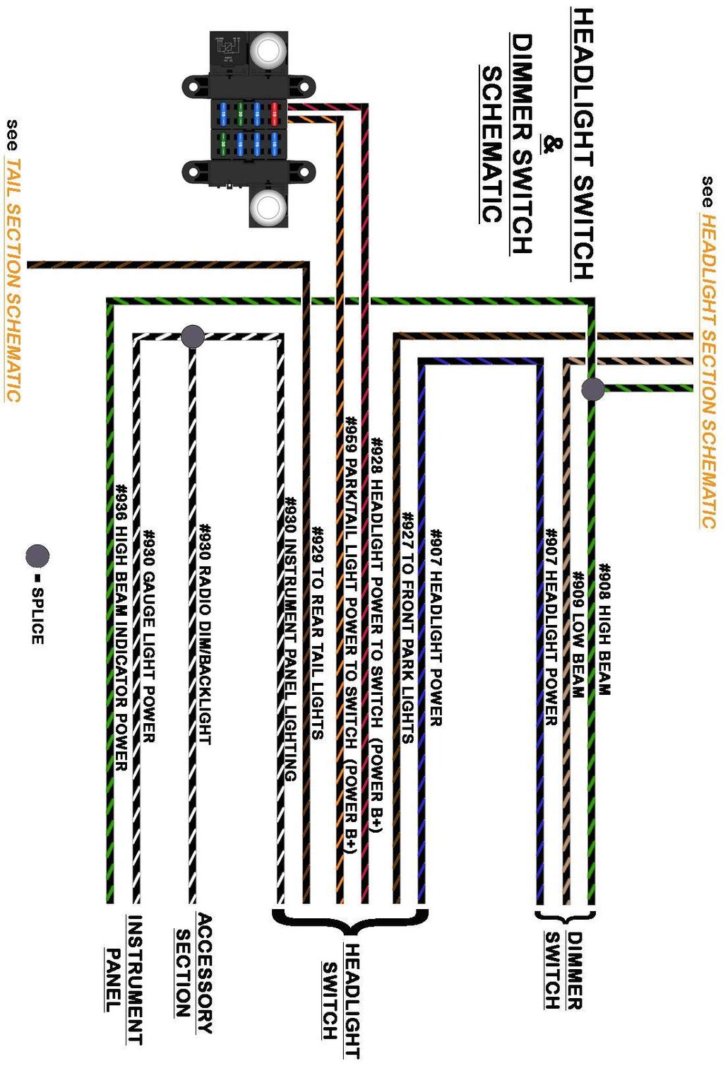
67 61


68 GM Headlight Switch Use the following diagrams to connect to a GM style headlight switch. GM used this style switch from the 1960 s up through the 1980 s. There are 2 different types of these switches, commonly referred to as early and late styles. The only difference is the tab to which the park lights connect, see the diagrams for this difference. Painless offers the early style switch, with a headlight pull, terminals and a connector as part #80152, seen in the photo to the right. If you do not have a connector, use the light blue insulated terminals found in the parts kit to make these connections. 62


69 Ford Headlight Switch Use the following diagram to connect to a Ford style headlight switch. This style switch was common on Ford vehicles used in the 1960 s and 1970 s. Use the insulated terminals found in the parts kit to make these connections. Painless Universal Headlight Switch Painless offers several universal switches, one even with hi low beam dimmer functions. Use the following diagrams to connect to either of the universal headlight switches offered by Painless. Use the blue insulated ring terminals found in the parts kit to make these connections. 63
 toggle or rocker switch. This will also require the use of 2 SPST relays.")

70 Toggle/Rocker Headlight Switch Some vehicles such as t-buckets and others which may have a smaller narrower dash board, may not have room or want the clutter of a bigger headlight switch. Reference the diagrams below to install a lighted or non-lighted SPST (Single Pole Single Throw) toggle or rocker switch. This will also require the use of 2 SPST relays. The small black and red lines and seen in the diagrams are wires that need to be provided by the installer, these can be small 18 gauge wires since they are only providing ground/ power for relay activation and power for the backlighting of a switch. The diode seen in the diagram is the same as the diode provided in the alternator bag kit, page 42 of the first manual. If you are not using the diode with your alternator it may be used for this purpose, if you need a diode, Painless offers #
 as seen below.")
71 Those using a lighted toggle/rocker switch, connections are the same as a nonlighted only you will need to provide a power source to the backlight of the switch. This will generally be a tab on the back of the switch that is opposite of the terminals for the input and output(s) as seen below. You can get a battery power 12v source from either the #928 or #959 wires of the headlight switch section. NOTES 65


72 TURN SIGNAL SWITCH The turn signal switch will provide power to each turn signal and turn signal indicator. For those using a later model or aftermarket GM style column, the turn signal switch also has a built in hazard switch. Those with a separate hazard switch, this section of the instructions will also cover that. As noted on page 15 of the first manual, if LED lights are being used a no load flasher may be needed, Painless part number # In this group of instructions you will see the term integrated turn/brake lights. Most hot rods/street rods will have integrated lights. This terminology refers to turn signals that also function as brake lights. You can easily tell if your vehicle has integrated turn/brake signals or separate by looking at the lamp socket(s) on the rear of the vehicle. Only looking at the passenger or the driver side, how many sockets going into red lenses do you see? Integrated turn brake signal vehicles will usually have 1 socket with dual filaments (brighter filament for turn/brake, dim filament for tail lights). You can also have vehicles that have integrated lights but also have multiple sockets and lenses. Separate turn brake signal vehicles will usually have 2 or 3 sockets: 1 socket with dual filaments (brighter filament for brake, dimmer for turn signal) and 1 socket with a single filament (dim filament for tail lights). Remember to count the bulb filaments or the contacts on the bottom of the bulb, not the wires going to them, as your sockets may or may not have ground wires. 66
73 The wires provided in the Painless harness for turn signal connection can be identified by the section label reading TURN SWITCH. These wires can be seen in the Turn Signal Schematic on page 77, they are: Black: 18 gauge wire, printed [TURN SIGNAL SECTION] #953 TO HORN BUTTON (HORN ACTIVATION), this wire is a ground activation signal to the horn relay. The only time this wire will be grounded is when the horn button on the steering wheel makes contact to a ground source. Black/Light Blue: 16 gauge wire, printed [TURN SWITCH] #926 TO LEFT FRONT TURN SIGNAL, this wire will provide power to the left turn signal indicator on the gauge cluster as well as power to the front left turn signal. This wire will have power anytime the hazard switch is activated and also when the turn signal lever is in the down/left turn position and the ignition switch is in the ON/RUN position. Black/Blue: 16 gauge wire, printed [TURN SWITCH] #925 TO RIGHT FRONT TURN SIGNAL, this wire will provide power to the right turn signal indicator on the gauge cluster as well as power to the front right turn signal. This wire will have power anytime the hazard switch is activated and also when the turn signal lever is in the up/right turn position and the ignition switch is in the ON/RUN position. Black/Brown: 16 gauge wire, printed [TURN SIGNAL SWITCH] #951 TO HAZARD SW. (B+ FROM FLASHER), this wire provides power to the hazard switch. It comes from the hazard flasher found on the fuse block. It is a battery power wire but it will have power only when the hazard switch is activated, which causes the flasher to send power through this wire. See Flashers on page 14 of the first manual for how this process works. Black/Purple: 16 gauge wire, printed [TURN SIGNAL SWITCH] #952 TO TURN SWITCH (IGN. POWER FROM FLASHER), this wire provides power to the turn signal switch. It comes from the turn signal flasher found on the fuse block. It is an ignition power wire but it will have power only when the turn signal switch is activated, which causes the flasher to send power through this wire. See Flashers on page 14 of the first manual for how this process works. Black/Yellow: 16 gauge wire, printed [TURN SWITCH] <<#949 TO REAR LEFT TURN>> [TAIL SECTION], this wire provides power to the left rear turn signal. This wire will have power anytime the hazard switch is activated and also when the turn signal lever is in the down/left turn position and the ignition switch is in the ON/RUN position. On vehicles with integrated turn/brake lights, this wire also carries the brake light power wire. In those cases this wire will also have power anytime the brake pedal is pressed. Black/Green: 16 gauge wire, printed [TURN SWITCH] << #948 TO REAR RIGHT TURN >> [TAIL SECTION], this wire provides power to the right rear turn signal. This wire will have power anytime the hazard switch is activated and also when the turn signal lever is in the up/right turn position and the ignition switch is in the ON/RUN position. On vehicles with integrated turn/brake lights, this wire also carries the brake light power wire. In those cases, this wire will also have power anytime the brake pedal is pressed. 67
![Black: 18 gauge wire, printed [TURN SIGNAL SECTION] #969 HORN BUTTON GROUND SOURCE, this wire is a ground source to the horn button.](/docs-images/90/103923551/images/74-0.jpg "This wire will provide a clean chassis ground source to the steering column. If you are using a GM or Mopar steering column, this wire will not be needed.")
![Black/White: 16 gauge wire, printed [TURN SIGNAL SWITCH] #918 BRAKE LIGHT SIGNAL, this wire will feed the brake light power into the turn signal switch for vehicles with integrated turn/brake signals.](/docs-images/90/103923551/images/74-1.jpg "This wire will have power anytime the brake pedal is pressed. Those with separate turn and brake lights will not need this white #918 wire. Route the Turn signal wires to the turn signal switch.")
74 Black: 18 gauge wire, printed [TURN SIGNAL SECTION] #969 HORN BUTTON GROUND SOURCE, this wire is a ground source to the horn button. This wire will provide a clean chassis ground source to the steering column. If you are using a GM or Mopar steering column, this wire will not be needed. Black/White: 16 gauge wire, printed [TURN SIGNAL SWITCH] #918 BRAKE LIGHT SIGNAL, this wire will feed the brake light power into the turn signal switch for vehicles with integrated turn/brake signals. This wire will have power anytime the brake pedal is pressed. Those with separate turn and brake lights will not need this white #918 wire. Route the Turn signal wires to the turn signal switch. If your hazard switch is not on the column, black/brown wire #951 will route to the hazard switch. Using one of the following turn switch diagrams, connect each wire of the Turn Signal Switch section to its correct connection. GM Columns / Aftermarket GM style columns Locate the black connectors found in the bag kit that fits your column. Most columns will use the 4 ¼ plug, seen below, found on most aftermarket columns as well as mid GM columns which are a popular retro fit item because of their key on the column and tilt function. Locate the terminals supplied in the parts kit, seen below, and terminate each wire of the Turn Signal Switch Section. Using the diagram on the next page, pin each wire into its correct location on the connector. Remember, black/white #918 will only be connected if you have integrated lights. Also, black #969 will not be needed; it may be connected to a clean chassis ground source or removed from the harness. If using the 4 ¼ connector, once all wires have been installed, fold the locking tab down onto the connector. It will click/snap, locking the terminal in their place. Connect the now installed connector onto the connector on the steering column. 68

75 Ford Columns For those with Ford columns, the connector that plugs into the connector on the column from a factory harness will be needed. When it is cut from the factory harness leave 4-6 of wire to make it easy to splice/connect it to the wires on the new Painless harness. Those that do not have access to the connector that plugs into the column connector, cut the connector off the column and splice/connect directly to the wires in the column. If a mate to your column connector is not available Painless recommends putting an in line connection to make removal of the harness or column easy. Connector kits such as #40010 and #40011 would provide such a connection; allowing you to install a connector onto the new Painless harness as well as a mate to this connector onto the wires on your column. Diagrams as well as a chart have been provided to help identify the factory wires found on your column. Your column may differ from the information provided as there are numerous different columns. Using the splices provided in the parts kit, splice each wire of the TURN SIGNAL SECTION to your factory connector or directly to the wires coming from your column. If you are using a Painless connector kit, use the supplied terminals provided with that kit. Ford Color Designation Painless Wire # Painless Color Grn, Red/Blk Brake Light Power 918 Blk/Wht Wht/Blu Front Right Turn Signal 925 BlkBlu Grn/Wht Front Left Turn Signal 926 Blk/Lt.Blu Orn/Blu, Grn Rear Right Turn Signal 948 Blk/Grn Grn/Orn, Ylw/Blk Rear Left Turn Signal 949 Blk/Ylw Wht/Red Hazard Power 951 Blk/Brn Blu Turn Signal power 952 Blk/Pur Blu, Blu/Ylw Horn 953 Blk Ylw Horn input 969 Blk 69


76 The diagrams above show splicing the wires from the to an installer created pigtail from factory wiring. 70

77 MOPAR Columns For those with Mopar columns, the connector that plugs into the connector on the column from a factory harness will be needed. When it is cut from the factory harness leave 4-6 of wire to make it easy to splice/connect it to the wires on the new Painless harness. Those that do not have access to the connector that plugs into the column connector, cut the connector off the column and splice/connect directly to the wires in the column. If a mate to your column connector is not available Painless recommends putting an in line connection to make removal of the harness or column easy. Connector kits such as #40010 and #40011 would provide such a connection; allowing you to install a connector onto the new Painless harness as well as a mate to this connector onto the wires on your column. Diagrams as well as a chart have been provided to help identify the factory wires found on your column. Your column may differ from the information provided as there are numerous different columns. Using the splices provided in the parts kit, splice each wire of the TURN SIGNAL SECTION to your factory connector or directly to the wires coming from your column. If you are using a Painless connector kit, use the supplied terminals provided with that kit. Mopar Designation Painless Painless Color Wire No. Color Wht Brake Light Power 918 Blk/Wht Tan, Blu Front Right Turn Signal 925 BlkBlu Grn, Lt. Grn Front Left Turn Signal 926 Blk/Lt.Blu Brn, Brn/red Rear Right Turn Signal 948 Blk/Grn Grn, Grn/Red Rear Left Turn Signal 949 Blk/Ylw Pnk, Blk Hazard Power 951 Blk/Brn Red Turn Signal power 952 Blk/Pur Blk, Blk/Red Horn 953 Blk Painless #30120 Painless Offers a Universal Turn Signal and Hazard switch kit for those with columns that do not have turn signals. This kit will provide Turn signal Switch as well as Hazard functions through 2 toggle switches and come with all relays preinstalled. This kit will work with either integrated or separate turn/brake lights. 71

78 If using the 30120, kit in can be installed two different ways: #1- This method takes no modifications to the chassis harness you are installing or to the kit. This will make the flashers found on the fuse block of the nostalgia harness useless. Connect the turn signal kit as the instructions provided with the indicate. Wires #951 & #952 of the chassis harness will not be used and can be removed from the harness; they go to the flashers found on the fuse block, which no longer have a purpose Using the fuse taps provided with the turn signal kit, switched power can be sourced from the WIPER/TURN fuse and Battery power for the flasher and hazard switch can be sourced from the TAIL LIGHTS/HAZARD fuse. These fuses can be seen on page 16 of the first manual. You cannot use #951 or #952 for these functions as they pass through flashers and will provide interrupted power. The turn signal wires of the Turn signal kit will connect to the TURN SIGNAL section wires of the chassis harness as shown below. Only connect #918 if you have integrated lights. 72

79 #2- This method slightly modifies the turn signal/hazard switch kit and allows you to use the hazard flasher and the #951 circuit of the Nostalgia harness. Start by following the instructions by mounting the relays. When you get to step #3 of the instructions, cut the purple wire on the kit about 4-6 away from the relays. This will allow you to remove the flasher connector and red wire printed B+ CONSTANT SOURCE from the kit. Wire #951, the BLACK/BROWN wire, from the nostalgia harness will now splice to the purple wire coming from the turn signal relays, this will allow you to use the fuse block mounted flasher instead of the inline flasher that comes pre-installed on the turn signal kit. The black/purple #952 will not be used. See the diagram below. Using the fuse taps provided with the turn signal kit, switched power can be sourced from the WIPER/TURN fuse and Battery power for the flasher and hazard switch can be sourced from the TAIL LIGHTS/HAZARD fuse. These fuses can be seen on page 16 of the first manual. The remainder of the turn signal kit will connect as it s instructions indicate. The turn signal wires of the Turn signal kit will connect to the TURN SIGNAL section wires of the chassis harness as shown below. Only connect #918 if you have integrated lights. 73


80 External/Clamp On Column Mounted Switch There are many versions of this typical hot rod/street rod style switch. In most cases this type of switch will have wires coming from it in which the chassis harness will connect. Do not try to match the color of the wires on your switch to the striped colors found on the Painless harness Due to so many variations and manufacturers of this type of switch, a specific pin out/ schematic cannot be given. A 3 pin flasher is generally suggested with these switches. This will allow the on board indicator lights of the switch to function properly. The Painless harness you are installing comes equipped with two 2 prong flashers which obviously will not work. However the fuse block can easily be modified to accept a 3 prong flasher to allow the turn signal and turn indicators on the switch to function properly. Locate the rolled piece of black/red wire provided with this kit. This wire will have print reading 3 PRONG FLASHER. Switches with HAZARD function: Looking at the back of the fuse block, locate the base for the hazard relay, this will be the top right base with two black/brown wires. Plug the terminal pre-installed on the black/red wire into the location circled in the diagram below. This will allow the turn signals and hazards to work at all times. Switches with TURN ONLY: Looking at the back of the fuse block, locate the base for the turn signal relay, this will be the single base to the left with two black/purple wires. Plug the terminal pre-installed on the black/red wire into the location circled in the diagram below. This will allow the turn signals to only work when the ignition is in the ON/RUN position. 74

81 SPDT Toggle switch Once installed, route this wire to the rest of the Turn Signal section Wires. Remove the 2 prong flasher from the base you modified. Replace it with a 3 prong 12v flasher, not included. Slight modification/dimpling to the 3 prong flasher housing may be necessary to clear the mounting screw of the flasher base on the fuse block. Follow the manufacturers instructions on proper connections of the wires from the switch.. #951 will connect to the wire the manufacturer states goes to connect to P on a 3 prong flasher, the black/red wire that was just added will connect to the wire labeled L on a 3 prong flasher. Refer to the Turn Signal Schematic on page 77 to help match the wires of your turn signal to the wires found on this chassis harness. If you do not have a turn switch, a simple On-Off-On SPDT switch can be used for this function. Please be aware that the diagram and instructions provided below are for separate turn/brake light vehicles only. Those with integrated lights are encouraged to purchase Painless part #30120 or a clamp on turn signal switch as seen on the previous few pages. Connect the #952 wire to the input of the switch. Connect the front and rear left turn signal wires, #926 & #949, to one position on the switch. Connect the front and rear right turn signal wires, #925 & #948, to the remaining position on the switch. Hazard Switch 75
82 For those with a hazard switch that is not part of the turn signal switch wires will need to be added by you, the installer, for proper connection. The only wire provided in this Painless harness for these functions is the power wire from the flasher, black/brown wire #951. Most hazard switches will have 4 or 5 pins: Power from the hazard flasher Power out to the front right turn signal Power out to the front left turn signal Power out to the brake lights (4 pin switches) or to rear left turn signal (5 pin switches) Power out to the rear right turn signal (5 pin switches) If you do not have a factory style hazard switch, a simple SPST switch can be used to flash only the brake lights in the event of an emergency. This diagram will not flash the front turn signals like a traditional hazard flasher which your local laws may require. The diagram below will show connection of the #951 wire. If you have separate turn brake lights, #918 can connect directly to the toggle. If you have integrated lights, then run a wire from the toggle switch and splice into the #918 wire. Horn Button If you are using an external/clamp turn signal or a toggle switch for turn signal activation, the remaining wires found in the turn signal section will be for horn function. These will be black wires #953 and #969. If you have a horn button on the column, how many wires do you have exiting the column? 1 wire: Connect the #953 wire to the horn button. #969 will not be needed as your column is grounded though the mounting. 2 wires: Connect both #953 and #969 wires. Your column is not grounded. #969 will provide a clean chassis ground source to one side of the horn button. If your column does not have a horn button, a momentary SPST switch can be used. This switch will have 2 prongs, toggle switches will look identical to the one seen above. Connect #953 to one prong and #969 will connect to the other. 76
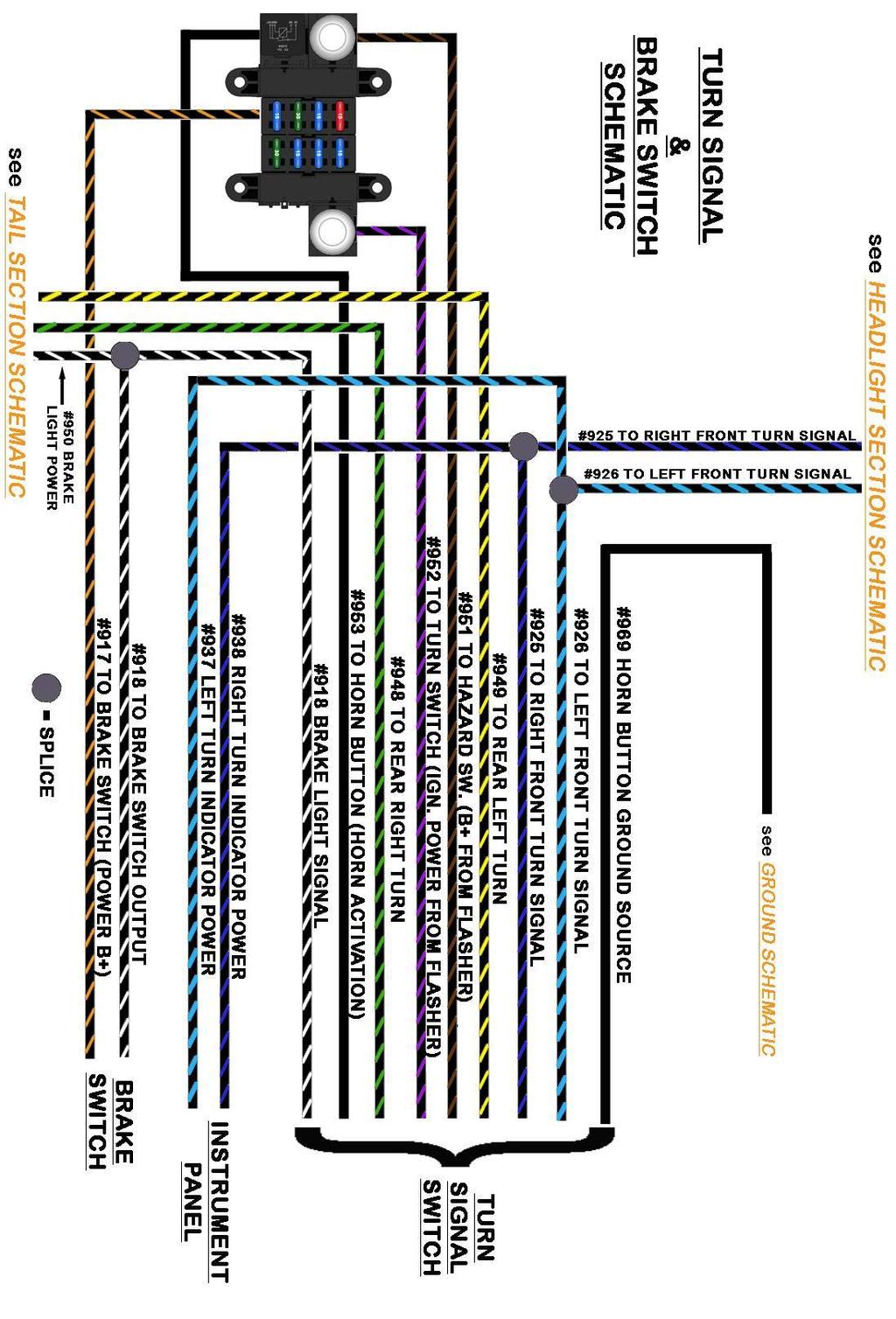
83 77

84 BRAKE SWITCH The location of the brake switch will vary from vehicle to vehicle as this connection depends on the style switch your vehicle uses. Hydraulic switches, like Painless #80171, will be mounted in the engine compartment usually near or on the master cylinder. A mechanical switch, like Painless #80172 (2 pin) or #80176 (4 pin, also included in our torque converter lock up kits #60109 & 60110), will be mounted on or near the pivot point of the brake pedal. There are two wires found in the chassis harness for proper Brake Switch connection, they will be identified will tags reading BRAKE SWITCH, they are: Black/Orange: 16 gauge wire, printed [BRAKE SWITCH] #917 TO BRAKE SWITCH (POWER B+), which provides power from the 15 amp STOP fuse. This wire will have power at all times. Black/White: 16 gauge wire, printed [BRAKE SWITCH] #918 TO BRAKE SWITCH OUTPUT. This wire supplies power from the brake switch to the brake lights. This wire goes into a splice with 2 other wires. This splice can be seen in the Turn Signal Schematic on the previous page. Route the brake switch wires to the brake switch and connect using the loose piece insulated terminals provided in the parts kit. Be sure to route the wires away from the moving parts of the brake pedal and/or clutch pedal. If your brake switch has four connection pins: Two pins will have contact or will be closed when the brakes are not applied; this will usually be the pair of terminals closest together. These pins are for cruise control and/or torque converter lock up Two pins will be separate or open when the brakes are not applied. This will usually be the pair of terminals further apart. You will need these two posts that are normally open for brake light function. 78

85 IGNITION SWITCH The most important connection of a wire harness, the ignition switch, will control power to the switched ignition fuses on the fuse block as well as sending a start signal to the starter to allow engine operation. The ignition switch connection consists of wires with section labels reading IGNITION SWITCH. All wires going to the ignition switch can be seen in the Ignition Switch Schematic below, these wires are: 2 Black/Red: 12 gauge wires, printed [IGNITION SWITCH ] #934 TO IGNITION SWITCH POWER B+, these wires come from a buss bar on the fuse block and feed battery power to the ignition switch. These wires will have power at all times. Black/Orange: 12 gauge wire, printed [IGNITION SWITCH] #933 TO IGNITION SWITCH "IGN" TERMINAL, this wire provides the switched power source to the fuse block. This wire powers all of the switched power circuits to the harness, with the exception of the RADIO/REVERSE fuse. This wire will only have power when the ignition switch is in the ON/RUN position. Pink/Black: 16 gauge wire, printed [IGNITION SWITCH ] #931 TO IGNITION SWITCH (COIL), this wire provides power from the ignition switch to the COIL/FUEL PUMP fuse on the fuse block. This wire will have power when the ignition switch is in the ON/RUN position as well as the START position. Black/Purple: 12 gauge wire, printed [START/CHARGE] STARTER "S" TERMINAL #919 IGNITION SWITCH "START" [IGNITION SWITCH], this wire will send power to the starter solenoid and will only have power when the ignition switch is in the START position. Black/Brown: 12 gauge wire, printed [IGNITION SWITCH] #932 TO IGNITION SWITCH ACCESSORY TERMINAL, this wire carries power to the RADIO/REVERSE fuse on the fuse block. This #932 wire will have power when the ignition is in the ACCESSORY position and when in the ON/RUN position. 79

86 Since there are so many different types of ignition switches, chose from one of the following that best fits your application: GM Key on the Column Many of the popular retro fitted GM columns people use in their vehicles have the ignition key on the column. The diagram and instructions below instruct you on how to properly connect to this type of ignition switch. If you have connectors from the harness previously installed or from the donor vehicle your column came from, cut them from the harness leaving about 4-6 of wire coming from the connectors. This will create pigtails which will allow you to splice the new nostalgia harness to. Painless offers part #30805 and #30806 which have these connectors. Insulated terminals can also be used in the event you do not have connectors. Locate the ignition switch on the top of the steering column, seen in the photos on the next page, route the IGNITION SWITCH wires to the switch and cut them to length. If you are using insulated terminals to make these connections, install the terminals on the IGNITION SWITCH wires at this time. Using the diagram above, properly match the wires from the harness to the proper pin location, use splices provided in the parts kit to make these connections if you are using a connector pigtail. The connectors must be installed in a specific order; the clear connector will need to be connected first, and then the black. Part of the black connector will overlap the clear connector as seen at the top of the next page. If you are using insulated terminals to make these connections, install the wires onto the pins of the ignition switch as shown in the diagram above. 80


87 GM Key on the Dash Your vehicle may have one of the many different dash mounted ignition switches GM used until the early 1980 s. Most will have functions printed next to each pin on the switch to allow for identification as to where wires will connect. Below you will find diagrams showing the proper connection of a couple of these popular switches. 81


88 Ford Key on the Dash Below you will see a diagram to a common Ford dash mounted ignition switch. This switch was used on many cars and trucks throughout the 1960 s and 1970 s. It is easily identified by a thread post that comes out of the center; position C in the drawing below. Pin D will provide a ground source to warning/ idiot lights when the ignition switch is in the ON position and the vehicle is not running. This will give the driver a visual indication that all warning lights have functioning bulbs. Connections for this pin are not supplied in this harness but can easily be added by the installer. Painless #80153 Painless offers a universal dash mount ignition switch. This switch will come with the trim ring, which screws onto the switch to hold the switch in place, as well as 2 keys. The switch can be found as part #80153 or in switch kit # Insulated ring terminals found in the parts kit will be used to make these connections. 82
89 INSTRUMENT PANEL The instrument panel connections of the Painless harness will vary according to the gauge cluster or aftermarket gauges you are using. The wires for this connection will be grouped together with a section label reading INSTRUMENT PANEL, these wires are: Black: 16 gauge wire, printed [INSTRUMENT PANEL] #969 TO GAUGE GROUND, this wire provides a ground source for the gauges. This wire is tied into the ground circuit and can be seen in the Ground Schematic on page 14. Black: 16 gauge wire, printed [INSTRUMENT PANEL] #969 GAUGE LIGHT GROUND, this wire provides a ground source to the backlighting of the gauges. This wire is tied into the ground circuit and can be seen in the Ground Schematic on page 14. Black/White: 18 gauge wire, printed [INSTRUMENT PANEL] #930 GAUGE LIGHT POWER, this wire will provide a power source for gauge back lighting. The black/white #930 is tied to the other #930 wire coming from the headlight switch that goes to the radio backlight/dim. This wire will have power anytime the headlight switch is in the Park/Tail Lights ON or Headlights ON position. This wire can also be seen in the Headlight Switch Schematic on page 61. Black/Tan: 18 gauge wire, printed [TAIL SECTION] <<FUEL SENDER #939 FUEL GAUGE>> [INSTRUMENT PANEL ], this wire is a ground signal from the fuel level sending unit in the fuel tank. The resistance to ground will vary on this wire according to the amount of fuel in the tank. This wire can also be seen in the Tail Section Schematic on pages 100 & 101. Black/Pink: 18 gauge wires, both printed [INSTRUMENT PANEL] #935 TO GAUGE/VOLTMETER POWER, this wire provides a switched ignition power source to the cluster. This wire comes from the 10 amp GAUGES fuse on the fuse block. This wire will have power anytime the key is in the ON/RUN position. Black/Green: 18 gauge wire, printed [ENGINE SECTION] TO TEMP SENDER #921 TO TEMP GAUGE [INSTRUMENT PANEL], this wire is a ground signal from the engine coolant temperature sending unit. The sending unit will create resistance to ground according to engine temperature. This resistance is transferred through this wire to the gauge. This wire can also be seen in the Ignition Switch Schematic on page 79. Black/White: 18 gauge wire, printed [ENGINE SECTION] COIL(-) #923 TACHOMETER SIGNAL [INSTRUMENT PANEL], this wire is a ground signal from the negative side of the ignition coil. This wire can also be seen in the coil connection diagrams on page 34. Black/Lt. Blue: 18 gauge wire, printed [ENGINE SECTION A] TO OIL SENDER #922 TO OIL GAUGE [INSTRUMENT PANEL SECTION], this wire is a ground signal from the oil pressure sending unit. The sending unit will create resistance to ground according to oil pressure. This resistance is transferred through this wire to the gauge. 83
90 Black/Lt. Blue: 18 gauge wire, printed [INSTRUMENT PANEL] #937 LEFT TURN INDICATOR POWER, this wire is a power activation wire for the left turn signal indicator. This wire is spliced into the wire going to the front left turn signal. It will have interrupted switched ignition power, through the turn flasher, anytime the left turn signal is activated. It will also have interrupted switched battery power, through the hazard flasher, anytime the hazard switch is activated. This wire can also be seen in the Turn Signal Switch Schematic on page 77. Black/Lt. Green: 18 gauge wire, printed [INSTRUMENT PANEL] #936 HIGH BEAM INDICATOR POWER, this wire is a power activation wire for high beam indicator. This wire is spliced into the wire coming from the high beam side of the dimmer switch, to the headlights. This wire will have power anytime the headlight switch is in the HEADLIGHT ON position and the dimmer switch in the HIGH BEAM position. This wire can also be seen in the Headlight Section Schematic on page 30. Black/Blue: 18 gauge wire, printed [INSTRUMENT PANEL] #938 RIGHT TURN INDICATOR POWER, this wire is a power activation wire for the right turn signal indicator. This blue wire is spliced into the wire going to the front right turn signal. It will have interrupted switched ignition power, through the turn flasher, anytime the right turn signal is activated. It will also have interrupted switched battery power, through the hazard flasher, anytime the hazard switch is activated. This wire can also be seen in the Turn Signal Switch Schematic on page 77. The following instructions will be universal in nature due to all the different manufacturers of aftermarket gauges. Use the following instructions along with the gauge manufacturer s instructions. Most electric aftermarket gauges require four or five wire connections: Gauge Power- a Switched 12 volt power source Gauge Ground (some gauges do not require this) Signal- from a sensor or sending unit Gauge Light Power- 12 volt power source from the Gauge Lighting circuit Gauge Light Ground Most mechanical aftermarket gauges only require two wires to be connected: Gauge Light Power- 12 volt power source from the Gauge Lighting circuit Gauge Light Ground All of these connections are present in the wiring Painless harness. However if will be up to the installer to distribute the power for the gauge and the gauge lights as well as the grounds. This additional splicing will be dependent on the method the gauge wires are connected to the gauges. There are two methods to connecting aftermarket gauges: Separate harness Hard wiring 84


91 Separate harness: To facilitate wiring aftermarket gauges, Painless offers and recommends the use of Painless part # (#30302 if using an electric speedometer). This will be a universal gauge cluster harness that has all the splicing and termination preinstalled for these types of applications. This harness will also offer you the benefit of having an inline connector instead of hardwiring the chassis harness directly to the gauges. Using the terminals and connector found in the or kit, install the wires of the nostalgia chassis harness according to the diagram below. Use the numbers on the connectors as well as the circled reference points in the diagram for proper cavity location. Black wire #969 GAUGE LIGHT GROUND will not be used. Hard Wiring: Those choosing to wire aftermarket gauges with just the wires found in the Painless chassis harness, and not purchasing an additional gauge harness, the following steps will walk you through the process of distributing power and ground, as well as connecting the sender wires. The following diagrams only show temp, oil pressure, volt and fuel level gauges. Power, ground and sender wires will connect in the same manner to speedometers and tachometers. Power to the gauges will need to come from the Black/Pink #935 wire. Power will need to be connected to the I or 12v post on each gauge. The power wire can be connected in one of two ways: 85


92 #1) Splicing- This is when you connect multiple wires to a single wire to distribute power/ground to multiple components. In this case, splice off the #935 wire and running wires to several gauges to provide power to each gage. #2) Chaining or Jumpering- Run the #935 wire to a power post, before terminating the wire with the proper terminal, you will insert another wire into the terminal and crimp. You will now have 2 wires in one terminal. This additional wire will then route to the power post on another gauge. Before terminating that wire with the proper terminal, you will insert another wire into the terminal; and so on. 86


93 Grounds will need to be supplied to the gauge lights and to any ground tab on the gauges. These grounds can come from the black wires #969 TO GAUGE GROUND and #969 GAUGE LIGHT GROUND wire and/or seeing that a good ground source is not hard to find on vehicles, the installer could run their own ground circuit for gauge connections. To make these ground connections you can splice from these #969 wires to all the gauges or chain/jumper it all together. Both methods seen in the following two drawings: 87


94 Gauge light power will be supported by the Black/White #930 wire. This wire will connect to one of the leads for the gauge light, or to the gauge light tab found on gauges with LED backlighting. To make these connections you can splice from this #930 wire to all the gauges or chain/jumper it all together. 88

95 The last connections needing to be made will be the sending unit wires or signal wires. These will be the wires which come from the temperature sending unit, oil pressure sending unit, and fuel level sending unit. Not shown in the diagram, but also provided in the Painless chassis harness is the Black/White #923 TACHOMETER SIGNAL wire. NOTES: 89
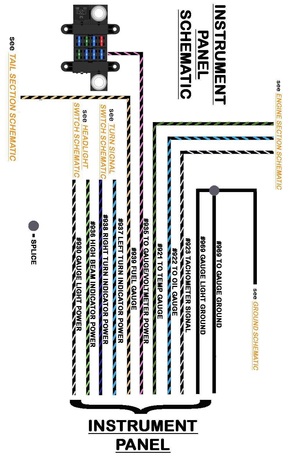
96 90

97 ACCESSORIES This Painless harness includes provisions for several accessory components which may or may not be used on your particular install. These accessories include radio, reverse switch, and wiper power. Below you will find information about each of these accessories and the wires provided in this harness to connect these accessories. Radio The radio connection on the Painless harness is set up for a universal application, meaning, the two power wire colors used by Painless reflect the colors most aftermarket companies use on radios manufactured today. The Painless harness includes four wires dedicated for a connection to the radio. These four wires are: Black/Yellow: 16 gauge wire, printed [ACCESSORY SECTION] #940 RADIO POWER (BATTERY), this wire will provide the radio a battery power source that will allow the time and radio presets to remain every time the ignition is turned off. This wire comes from the 10 amp RADIO fuse. This wire can be seen in the Accessory Schematic above. Black/Red: 16 gauge wire, printed [ACCESSORY SECTION] #941 RADIO POWER (SWITCHED), this wire will provide the radio with ignition switched power for operation. This wire will have power when the ignition switch is in the ACCESSORY and ON/RUN positions. This wire comes from the 10 amp RADIO/REVERSE fuse of the fuse block. This wire can be seen in the Accessory Schematic above. Black: 16 gauge wire, printed [ACCESSORY SECTION] #969 TO RADIO GROUND, this wire will supply a ground source to the radio. This wire is part of the ground circuit of the Painless harness. This wire can be seen in the Ground Schematic on page 14 of the first manual. 91
98 Black/White: 18 gauge wire, printed [ACCESSORY SECTION] #930 RADIO DIM/BACKLIGHT, this wire will provide a power signal to the radio to dim the back lighting/display during low light conditions. On older radios this power source will illuminate the backlighting. The black/white #930 is tied to the other #930 wire coming from the headlight switch to the gauge lights. This wire will have power anytime the headlight switch is in the Park/Tail Lights ON or Headlights ON position. This wire can be seen in the Headlight Switch Schematic on page 61. If you have a gear indicator light on a floor mount shifter, you will need to link a wire from the #930 wire at the radio to one side of the gear indicator light. Linking or Chaining was explained on page 86 in the Instrument Panel instructions. Linking from the #930 wire will provide power to the gear indicator light. The ground side of the gear indicator light can be connected directly to a clean chassis ground source, either from a wire or directly to the floor pan/transmission tunnel. Reverse Switch If you are using an aftermarket radio, refer to the manufacturer s installation guide for proper connection. Splices and quick disconnect terminals have been provided in the parts kit. If you are using a factory radio, a factory schematic for the vehicle it came out of will be needed to identify the connections to the radio. Many older radios require one power source, Painless recommends connecting the #941 to the radio in these circumstances so that the radio will only operate when the ignition switch is in the ACCESSORY or ON/RUN position. This will prevent the radio from draining the battery if it is accidentally left on. The reverse switch connection will provide the backup lights the power they need to illuminate. This switch is a 2 pin normally open switch that has power coming into one side and power going out the other side to the backup lights. When the shifter is put into the reverse position, contact is made between these two pins, closing the switch. This allows power to flow from one pin to another, transferring power through the switch out to the backup lamps. The two wires provided for this option are: Black/Pink: 16 gauge wire, printed [ACCESSORY SECTION] #958 REVERSE SWITCH INPUT/IGN POWER ACCESSORY, this wire comes from the 15 amp RADIO/REVERSE fuse on the fuse block. This wire is a switched ignition power wire meaning it will only have power when the ignition switch is in the ACCESSORY and ON/RUN positions. If you do not have back up lights, #958 can be used to power an accessory requiring a switched 12v power source. Black/Light Green: 16 gauge wire, printed [ACCESSORY SECTION] #923 POWER FROM REVERSE SWITCH [TAIL SECTION], this wire provides power from the reverse switch to the backup lights in the Tail Section of the Painless harness. 92


99 Locate the reverse switch; location will depend on your column/shifter. If you are using a factory GM column, it can be found at the base of the steering column as seen below. If you are using an aftermarket floor mounted shifter, this switch may be found on the base of the shifter. There may also be a Neutral safety switch found on the shifter as well. When testing the system, if you notice the revere lights on when the transmission is in park or neutral, you have the reverse switch wires connected to the neutral safety switch. Small insulated terminals have been provided in the parts kit to accommodate aftermarket shifter reverse switches. Painless offers part #80175 for those using GM 350, 400, or 700r4 transmissions. This part can be used as either a reverse switch or a neutral safety switch. 93
100 Wiper Power The last wire of the ACCESSORY section is wire intended for windshield wipers. If you do not have a wiper system, this wire can be used to power some other accessory so long as the max amperage does not exceed 10 amps. This wire is: Black/Yellow: 16 gauge wire, printed [ACCESSORY SECTION] #905 TO WIPER POWER/ACCESSORY (IGN. POWER), this wire will supply switched ignition power to the wiper motor/switch from the 15 amp WIPER/TURN fuse on the fuse block. Since we at Painless have no idea what system or what speed wiper your particular install is using, we only provide power to the system. It will be up to you the installer to add additional wires from the wiper switch to the wiper motor for correct operation. GROUND A single wire can be found in this harness that is intended to connect to a clean chassis ground source. This wire will have a section label reading GROUND, it is: Black: 10 gauge wire, printed #969 GROUND, this wire will supply a ground source to the ground wires as it is is part of the ground circuit of the Painless harness. This wire can be seen in the Ground Schematic on page 14. Route the Ground wire to a clean chassis ground source. Grounds were explained on page 12 of the first manual. If the fuse block was mounted to a metal surface, the bolts holding the fuse block in place would be an ideal place. Cut the wire to length, strip ¼ of insulation from the wire and using a ring terminal from the parts kit, connect this wire to a clean chassis ground source. NOTES: 94

101 TAIL SECTION The tail section wires are the last group to be connected. This group of wires will connect to things like right & left turn signals, tail lights, reverse lights, license plate light, fuel level sending unit and there is even a provision for an electric fuel pump. All wires found in the Tail Section can be seen in the two schematics found on pages 100 & 101. Fuel Pump Route the wires with the section label reading TAIL SECTION to the rear of the vehicle. Make sure to avoid pinch point around door/trunk hinges and moving parts like window regulators. Read the Fuel pump instructions below as this wire may or may not route to the tail section in your application. In the tail section of the harness you will find a wire to provide power to an electric fuel pump. This fuel pump wire can be pulled from the Tail Section of the harness and routed through the firewall depending on where you have the fuel pump mounted or if you are powering some other accessory with this wire if you are using a mechanical pump. The wire for the fuel pump will be a single open ended wire, it is: Black/Pink: 14 gauge wire, printed [TAIL SECTION] #947 FUEL PUMP/ACCESSORY (IGN. POWER), this wire will provide a power source to the fuel pump. This wire comes from the 30 amp COIL/FUEL PUMP fuse on the fuse block and will only have power when the ignition switch is in the ON/RUN position and the START position. If a mechanical pump is being used, insulate the end of this wire with an insulated terminal from the parts kit and tape the wire up into the harness and proceed to the next connection. This wire can also be used to power an accessory requiring a switched 12v power source. This accessory cannot require more than 15 amps. If an electric fuel pump is being used, route the #947 wire to the power or + post/tab/wire of the fuel pump. Several different small grommets have been provided in the parts kit to allow you to *drill a hole through the floor pan or firewall to make this connection easier. *Note: If a hole in to be drilled in the trunk pan, be sure to not puncture the fuel tank. Also before a hole is drilled make sure there is no other way to get the #947 wire to the fuel pump. Using an insulated terminal that matches the connection your pump requires, connect the #947 wire to the power or + post/tab/wire of the fuel pump. 95
102 Fuel Sending Unit At this time you will need to provide a ground wire. This harness does not provide a ground wire specifically for this component, but a ground can be easily connected using insulated terminals from the parts kit and a length of scrap wire created during a previous connection. The fuel level sending unit will send a ground signal to the fuel level gauge. The float inside the tank will move up and down with the level of fuel in the tank. This movement will move an arm/contact across a resistor of the sending unit sending a resisted signal to the fuel level signal. The amount of resistance the gauge sees will be evident based on the reading of the gauge. In order for the fuel gauge to work properly, the fuel level sending unit operating range must match the gauges operating range. One wire is included in this Painless kit for this function, it is: Black/Tan- 18 gauge wire, printed #939 Fuel Level Sending Unit, this wire will send the ground signal from the fuel level sending unit to the fuel level gauge. Route the #939 wire to the fuel level sending unit. Several different small grommets have been provided in the parts kit to allow you to *drill a hole through the floor pan or firewall to make this connection easier if your sender is located under the vehicle. *Note: If a hole in to be drilled in the trunk pan, be sure to not puncture the fuel tank. Also before a hole is drilled make sure there is no other way to get the #939 wire to the fuel pump. Turn/ Brake Lights Terminals have been provided in the parts kit to allow connection. The sending unit must be grounded in order to work properly; Painless does not offer a wire specifically for this. Some sending units will have a tab for a ground connection while others may rely on the sending unit mounting. If your sending unit has a ground tab, run a wire from a clean chassis ground source to this tab. If you do not have a ground tab, run a ground wire from a clean chassis ground source to one of the mounting bolts of the sending unit. Do not rely on a ground through the mounting of the sending unit to the tank. Connection to the turn signal/brake lights will depend on if your vehicle has integrated or separate turn/brake signals, both explained on page 66. Furthermore, if your light sockets ground themselves through the mounting a ground wire, seen in the Tail Section Schematics on pages 100 and 101, may not be needed. To begin connection to the turn/brake lights, locate the four wires in the tail section dedicated for these functions, they are: 96
103 Black/Yellow- 16 gauge wire, printed #949 REAR LEFT TURN SIGNAL POWER, this wire provides power to the left turn signal. This wire will have power anytime the turn signal is in the down/left position and the ignition switch is in the ON/RUN position. Vehicles with integrated turn/brake signals, this wire is also the brake light power and will also have power anytime the brake pedal is pressed and also anytime the hazard switch is activated. This wire can be seen in the Turn Signal Schematic on page 77 of this manual. Black/Blue- 16 gauge wire, printed #948 REAR RIGHT TURN SIGNAL POWER, this wire provides power to the left turn signal. This wire will have power anytime the turn signal is in the up/right position and the ignition switch is in the ON/RUN position. Vehicles with integrated turn/brake signals, this wire is also the brake light power and will also have power anytime the brake pedal is pressed and also anytime the hazard switch is activated. This wire can be seen in the Turn Signal Schematic on page 77 of this manual. Black/White- 16 gauge wire, printed #918 BRAKE LIGHT POWER, this wire provides power to the brake lights on vehicles with separate turn/brake lights and will have power anytime the brake pedal is pressed and also anytime the hazard switch is activated. This wire can be seen in the Turn Signal Schematic on page 77 of this manual. Notice there is only one brake light wire going to the Tail Section. Since Painless has no idea if this wire will be needed in your particular application, and since it is not used in most applications, we only provide one wire to prevent additional unused power wires to be taped up in the harness. If separate turn brake sockets are used, it will be up to you the installer to splice or link this brake light power to both brake lights. If you have integrated turn/brake lights, install an insulated terminal on this wire and tape it up into the harness, this wire will not be used. Black- 14 gauge wire, printed #969 GROUND SUPPLY TO REAR LIGHTS, this wire provides a ground source for the rear lights and comes from a splice that is tied to a series of other splices that ties all the grounds in this harness together. This wire, along with all the other ground wires and splices, can be seen in the Ground Schematic on page 14 of the first manual. Notice there is only one ground wire going to the Tail Section. Since Painless has no idea how many ground wires will be needed in your particular application, it will be up to you the installer to splice or link grounds together to each light assembly/housing to the #969 ground wire. This #969 wire can also provide a good ground source to a ground distribution block, like Painless # Grounds can also be supplied to each light assembly/housing from a clean chassis ground source such as the body or rear frame. Loosely route the turn signal wires, #948 and #949, to the correct turn signal in which they connect. On housings/assemblies with a dual filament bulb this will be the brighter filament. 97
104 If you have separate turn/ brake lights, route the brake light wire, #918 to the closest brake light as well. On housings/assemblies with a dual filament bulb this will be the brighter filament. If your housing requires a ground source, ground wires will also need to be created at this time. Tail Lights Cut the wires to length and connect to the appropriate contact/wire in the housings/assemblies. Consult the manufacturer s instructions if you are using aftermarket assemblies. Splices have been provided to make these connections. In most cases your rear exterior lights will have at least one housing/assembly with a dual filament bulb. The tail light connections will connect to the dimmest filament(s) of this type of housing/assembly. Two wires are provided in the tail section for these connections, they are: 2 Black/Brown- 16 gauge wires, one printed [TAIL SECTION] #929 TO LEFT TAIL LIGHT and the other [TAIL SECTION] #929 TO RIGHT TAIL LIGHT, these wires will provide the tail lights power. These wires receive power from the headlight switch and will have power anytime the headlight switch is pulled into the PARK/TAIL LIGHT ON and HEADLIGHT ON positions. These wires can be seen in the Tail Section Schematic on page 100 &101 of this manual. Reverse Light Loosely route a #929 wire to each side of the vehicle. Depending on the vehicle or what housing/sockets you are using you may have more than one tail light on each side. To power additional tail light sockets and/or a license plate light, you will need to splice or link from a #929 wire over to the additional lamp. As seen in the diagrams on page 100 & 101. Cut the wires to length and connect to the appropriate contact in the housings/assemblies. Consult the manufacturer s instructions if you are using after market assemblies. One wire is provided in the tail section for reverse light connections, it is: Black/Green- 16 gauge wire, printed #956 REVERSE LIGHT POWER, this wires will provide power to the reverse or back up lights. This wire receives power from the reverse switch and will have power anytime the shifter is in the REVERSE position. Because most installs may not have reverse lights, only one wire has been provided to avoid having multiple power wires in the tail section that may not be used. 98
105 If your install requires connecting reverse lights, a splice or jumpering from one reverse light to the other will have to be done by you, the installer. If your vehicle does not have reverse lights, tape it up into the harness, this wire will not be used. This wire will only have power if it is connected to a reverse switch. This wire can also be removed from the harness if it is not being used. NOTES: 99
106 100
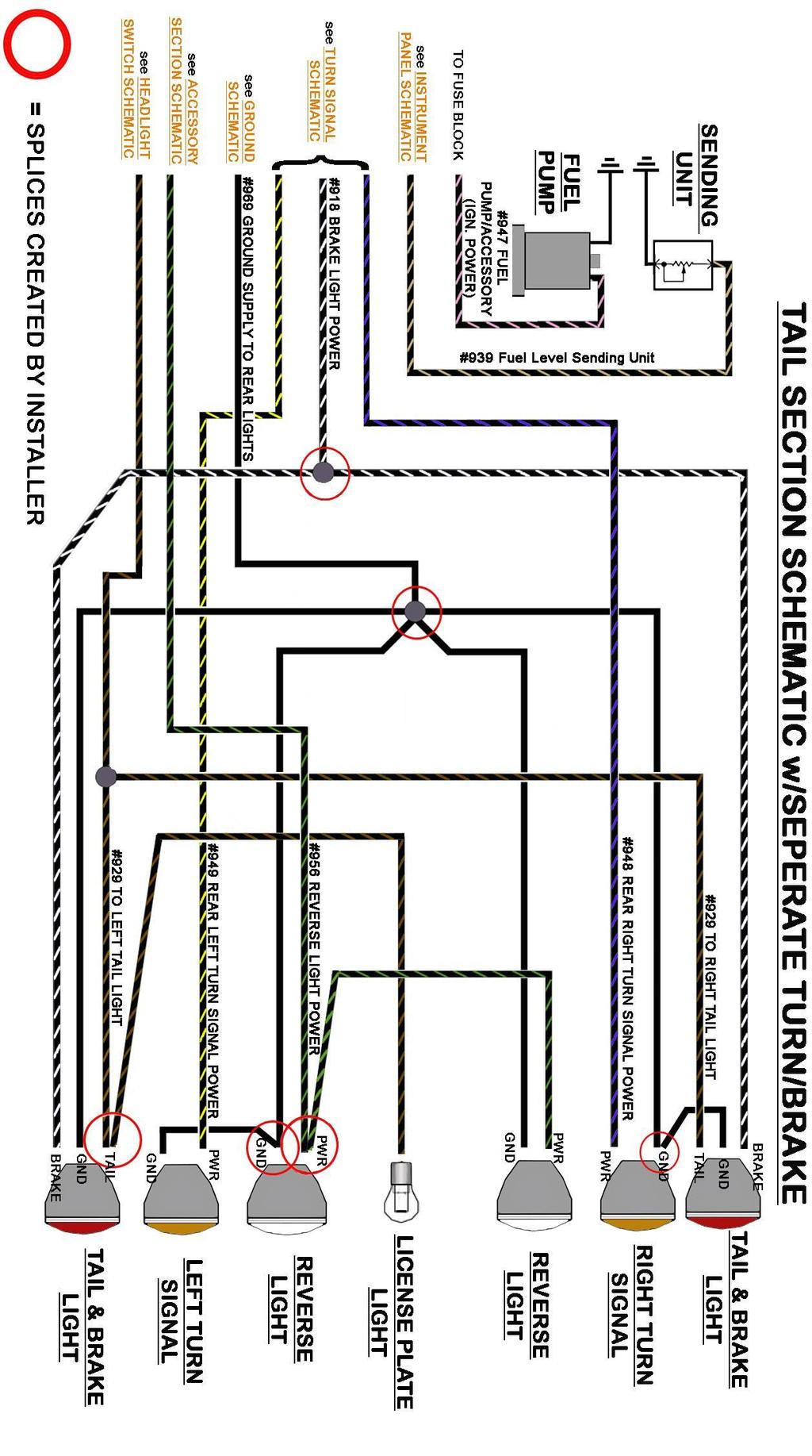
107 101

108 TESTING THE SYSTEM Use a small (10 amp or less) battery charger to power up the vehicle for the first time to test the circuits. If there is a problem anywhere, the battery charger's low amperage and internal circuit breaker will provide circuit protection. Make sure the Negative Battery cable is connected to the frame or engine block, and make sure there is a ground between the engine and frame. The negative battery cable should still be disconnected from the Battery as instructed on page 3 of the Engine Section Manual. Connect the Battery Positive cable to the Positive side of the Battery and also make sure this cable is connected to the B+ side of the Starter Solenoid. At this point this should also connect the red #915 from the MIDI fuse to the positive side of the battery, either through the starter lug or the battery lug. Connect the Battery Charger's NEGATIVE cable to the automobile chassis, engine block or to the disconnected Negative Battery cable. Do NOT connect the Battery Charger's NEGATIVE cable to the Battery. Connect the Battery Charger's POSITIVE cable to the automobile's positive battery terminal lug. INDIVIDUALLY turn on each light, ignition, wiper circuit, etc. and check for proper operation. Turn off each component before testing another. Note: If you try to test more than one circuit at a time, the charger will not provide enough amperage for each circuit to work correctly. 102
Track Rocker Installation Instructions
 Track Rocker Installation Instructions For Installing Painless Part Numbers: 58103: 8-Switch Customizable Track Rocker Switch Panel w/ Flanged Mount 58106: 6-Switch Customizable Track Rocker Switch Panel
Trail Rocker Installation Instructions
 Trail Rocker Installation Instructions Manual #90580 For Installing Painless Part Numbers: 57000 and 57001 Painless Performance Products recommends you, the installer, read this installation manual from
Trail Rocker Installation Instructions
 Trail Rocker Installation Instructions Manual #90581 For Installing Painless Part Numbers: 57002 Painless Performance Products recommends you, the installer, read this installation manual from front to
Wire Harness Installation Instructions
 Wire Harness Installation Instructions For Installing: Part #50001 Race Car Kit/8 Circuit Part #50201 8 Switch Dash Mounted Panel Part #50202 8 Switch Roll Bar Mounted Panel Manual #90502 Painless Performance
Trail Rocker Installation
 Trail Rocker Installation Instructions 4, 6, or 8 - Switch Customizable Trail Rocker Switch Panel w/ Flanged Mount For Installing Painless Part Number: 57103, 57106, & 57109 Manual #90636 Painless Performance
Trail Rocker Installation
 Trail Rocker Installation Instructions Customizable Trail Rocker Control System For Installing Painless Part Number: 57100 Manual #90616 Painless Performance Products recommends you, the installer, read
Wire Harness Installation Instructions Manual #90576 For Installing:
 Wire Harness Installation Instructions Manual #90576 For Installing: #20112 Direct Fit Camaro Harness 1970-73 #20113 Direct Fit Camaro Harness 1974-77 #20114 Direct Fit Camaro Harness 1978-81 All 26 Circuit
Track Rocker Installation Instructions
 Track Rocker Installation Instructions Customizable Track Rocker Control System For Installing Painless Part Number: 58100 Track Rocker Relay Center Manual #90641 Painless Performance Products recommends
Wire Harness Installation Instructions Manual #90563
 Wire Harness Installation Instructions Manual #90563 For Installing: #10113 Direct Fit 1966-1977 Bronco Harness 28 Circuit w/switches Perfect Performance Products, LLC Painless Performance Products Division
For Installing Harness Number: Manual #90627
 Wire Harness Installation Instructions For Installing Harness Number: 20205: 27 Circuit 1973-1987 GM Truck Manual #90627 Painless Performance Products recommends you, the installer, read this installation
Off-Road Switch Panel Installation Instructions
 Off-Road Switch Panel Installation Instructions 50330: Off-road 4 Toggle switches/dash Mount w/keyed Ignition Switch 50332: Off-road 6 Toggle switches/dash Mount w/keyed Ignition Switch Painless Performance
jegs.com
 Contents Wiring Harness w/ Fuse Panel Installation Instructions Turn Signal Plug w/ Terminals 2 Headlight Plugs 3/4 Grommet 10 ¼ Terminals 4 Ring Terminals 10 Wire Ties Fusible Link 2 Screws & Nuts 2 Plastic
Trail Rocker Installation Instructions
 Trail Rocker Installation Instructions Trail Rocker - Genesis Bracket For Installing Painless Part Number: 57200 Manual # 90591 To be used with Painless Kit # s: 57000-57005 Painless Performance Products
Installation Instructions. Part #65100
 Installation Instructions Part #65100 Perfect Performance Products, LLC Painless Performance Products Division 2501 Ludelle Street Fort Worth, TX 76105-1036 800-423-9696 phone 817-244-4024 fax Web Site:
Installation Instructions
 Installation Instructions Part #40120 Perfect Performance Products, LLC Painless Performance Products Division 2501 Ludelle Street Fort Worth, TX 76105-1036 800-423-9696 phone 817-244-4024 fax Web Site:
Installation Instructions. Manual # For Installing: Part # Painless Gauge Controller
 Installation Instructions Manual #90579 For Installing: Part #60650- Painless Gauge Controller Perfect Performance Products, LLC Painless Performance Products Division 2501 Ludelle Street Fort Worth, TX
INSTRUCTIONS. 20 Circuit Wiring Kit Instructions October 2009, Speedway Motors, Inc.
 1 MAIN FUSE PANEL The main fuse panel harness s designed to be mounted under the dash a the firewall in an area close to the steering column. The enclosed representation of the main dash harness shows
Wire Harness Installation Instructions
 Wire Harness Installation Instructions For Installing: #10127 Customizable Mopar Chassis Harness 21 Circuit Manual #90542 Painless Performance Products, LLC 2501 Ludelle Street Fort Worth, TX 76105-1036
WIRE HARNESS INSTALLATION INSTRUCTIONS
 WIRE HARNESS INSTALLATION INSTRUCTIONS For Installing: #10206 Classic Plus Customizable GM Pickup Chassis Harness 1967-72 28 Circuit Manual #90510 PERFECT PERFORMANCE PRODUCTS, LLC Painless Performance
PIN BULKHEAD CONNECTOR KIT
 2501 Ludelle Street Fort Worth, Texas 76105 817-244-6212 Phone 817-244-4024 Fax 888-350-6588 Sales 800-423-9696 Tech E-mail: painless@painlessperformance.com Web: www.painlessperformance.com 40130 22 PIN
Installation Instructions For 50330, 50331, 50332, and Off Road Switch Panels
 Installation Instructions For 50330, 50331, 50332, and 50333 Off Road Switch Panels 2501 Ludelle Street Fort Worth, Texas 76105 817-244-6212 Phone 817-244-4024 Fax 888-350-6588 Sales 800-423-9696 Tech
30140 F5 Dual Fan Controller
 30140 F5 Dual Fan Controller 1 2501 Ludelle Street Fort Worth, Texas 76105 817-244-6212 Phone 817-244-4024 Fax 888-350-6588 Sales 800-423-9696 Tech E-mail: painless@painlessperformance.com Web: www.painlessperformance.com
Instruction Part #90577
 Phantom Key Push Button Ignition System Instruction Part #90577 For Installing: Part # s 55000, 55001, 55002, 55003, 55004, & 55005 Perfect Performance Products, LLC Painless Performance Products Division
WIRE HARNESS INSTALLATION INSTRUCTIONS
 WIRE HARNESS INSTALLATION INSTRUCTIONS For Installing: #10205 Classic Plus Customizable GM Pickup Chassis Harness 1973-87 27 Circuit Manual #90507 Painless Performance Products, LLC 2501 Ludelle Street
accessory connection rear body connection 40G 17A instrument cluster and map lamp ground 150A,B 15A 14A Circuit Branch 500A fog lamp switch
 accessory rear body 19 9 11 instrument cluster and map 10A, 0 4 3 7 40G 18 30 17A 24 1A 14A 9 8A instrument cluster 4E 31 3 121 11 33 401 10A 39A 400 30 washer and wiper switch 93A, 94 93 glovebox, map
CLASSIC UPDATE WIRING KIT
 by Randy Irwin 1955-57 CLASSIC UPDATE WIRING KIT Randy Irwin - Technical Writer Randy has been involved in the Chevy parts business for over 25 years. He is a wizard at creating, making and modifying custom
Wire Harness Installation Instructions For Installing:
 Wire Harness Installation Instructions For Installing: #20106 Classic Plus Customizable Tri-Five Chevy Harness 28 Circuit #20107 Classic Customizable Tri-Five Chevy Harness 21 Circuit Manual #90553 Painless
Wire Harness Installation Instructions
 Wire Harness Installation Instructions For Installing: Part #20120 22 Ford Mustang (1965-1966) Manual #90526 Perfect Performance Products, LLC Painless Performance Products Division 2501 Ludelle Street
Wire Harness Installation Instructions For Installing: #20102 Classic Plus Customizable GM Muscle Car Chassis Harness 25 Circuit
 Wire Harness Installation Instructions For Installing: #20102 Classic Plus Customizable 1969-74 GM Muscle Car Chassis Harness 25 Circuit Manual #90552 Painless Performance Products Division Perfect Performance
40A A 40B. Horn Relay Connector. Brake Switch. Third Brake Light. Brake Switch. Brake Switch. Wires. page 3. Rear Body Feed Wires.
 Fuse Box Connections (viewed from underside) 4D 4C 4D 0 50 300 4C 43 7 39 3 6 4 93 A 2G 2F 2E 2D 2C 2B 2G 2F 2E 40 69A 2 1 5 27 69A 3A B 40A,B 11A,B 40A 156 Dimmer Dome Feed page 2 Horn Relay 2D 2 29 40B
INSTRUCTIONS 12 Circuit Wiring Kit Instructions
 Fan 47 9 56 4 7 6 72 40 45 48 5 8 6 Gauge Power Temp Sender Headlight Power Power Radio Constant Power Instruments and Dash Rear of Vehicle Ignition and Lights Fuse Panel & Front of Vehicle Horn Alt Excitor
INSTRUCTIONS Circuit Wiring Kit Instructions _2017. Fuse Box Connections. (viewed from underside) 2018, Speedway Motors, Inc.
 2018, Speedway Motors, Inc.") Fuse Box Connections (viewed from underside) 4D 4C 100 50 300 4D 4C 4B 4A 43 107 39 103 3B 2G 104 93 2F 2E 2D 2C 2B 40 69A 102 101 105 2G 2F 2E 3A A 2A B 40A,B 27 69A 106 201, Speedway Motors, Inc. 1 Fuse
Fuse Box Connections (viewed from underside) 4D 4C 100 50 300 4D 4C 4B 4A 43 107 39 103 3B 2G 104 93 2F 2E 2D 2C 2B 40 69A 102 101 105 2G 2F 2E 3A A 2A B 40A,B 27 69A 106 201, Speedway Motors, Inc. 1 Fuse
UNIVERSAL GAUGE WIRE HARNESS
 2650-1797-00 UNIVERSAL GAUGE WIRE HARNESS For Installing Auto Meter Electric Speedometer, Tachometer, And Short Sweep Electric Oil Pressure, Water Temperature, Fuel Level, and Volt Meter Gauges. This harness
Mustang Classic Update Series Kit
 accessory rear body 19 9 11 instrument cluster and map 10A, 0 4 3 7 40G 18 30 17A 24 1A 14A 9C 8A instrument cluster 4E 31 3 121 11 401 10A 3 400 30 washer and wiper switch 93A, 93 glovebox, map light,
30140 &30142 F5 Dual Fan Controller
 2501 Ludelle Street Fort Worth, Texas 76105 817-244-6212 Phone 817-244-4024 Fax 888-350-6588 Sales 800-423-9696 Tech E-mail: painless@painlessperformance.com Web: www.painlessperformance.com 30140 &30142
Installation Tips for your Remote Start system (for RS4LX>GMBP for GM vehicles)
") Installation Tips for your Remote Start system (for RS4LX>GMBP for GM vehicles) Thank you for purchasing your remote start from MyPushcart.com - an industry leader in providing remote starts to doit-yourself
Installation Tips for your Remote Start system (for RS4LX>GMBP for GM vehicles) Thank you for purchasing your remote start from MyPushcart.com - an industry leader in providing remote starts to doit-yourself
Installation Instructions for the Plug & Play Remote Start Package (EVOCHR4)
") T6002 v1.1 02/2013 Installation Instructions for the Plug & Play Remote Start Package (EVOCHR4) For CHRYSLER Town & Country 2008-2012 Review the remote start installation manual for safety instructions!
T6002 v1.1 02/2013 Installation Instructions for the Plug & Play Remote Start Package (EVOCHR4) For CHRYSLER Town & Country 2008-2012 Review the remote start installation manual for safety instructions!
Installation Instructions
 Installation Instructions Jeep JK Unlimited (2007 Present) Mounting Bracket and Air Line System Kit for ARB On-Board Twin Air Compressor (CKMTA12) Made in the USA Kit Contents: 1 Bracket for ARB Compressor
Wire Harness Installation Instructions
 Wire Harness Installation Instructions For Installing: #20121 Direct Fit Mustang Chassis Harness 1967-1968 22 Circuit Manual #90556 Perfect Performance Products, LLC Painless Performance Products Division
WIRE HARNESS INSTALLATION INSTRUCTIONS. For Installing: Part # Circuit Universal CJ Jeep Harness ( ) Manual #90513
 Manual #90513") WIRE HARNESS INSTALLATION INSTRUCTIONS For Installing: Part #10110 12 Circuit Universal CJ Jeep Harness (1975-86) Manual #90513 Perfect Performance Products, LLC Painless Performance Division 2501 Ludelle
WIRE HARNESS INSTALLATION INSTRUCTIONS For Installing: Part #10110 12 Circuit Universal CJ Jeep Harness (1975-86) Manual #90513 Perfect Performance Products, LLC Painless Performance Division 2501 Ludelle
Wire Harness Installation Instructions
 Wire Harness Installation Instructions FOR INSTALLING: PART #10108 20 CIRCUIT BRONCO HARNESS Manual #90521 Painless Performance Products Division Perfect Performance Products, LLC 2501 Ludelle Street,
Wire Harness Installation Instructions
 Wire Harness Installation Instructions For Installing: Part #20120 14 Circuit Ford Mustang (1965-1966) Manual #90526 Perfect Performance Products, LLC Painless Performance Products Division 2501 Ludelle
Wire Harness Installation Manual # Part # 60617
 Wire Harness Installation Manual #90572 For Installing: Part # 60617 26 Circuit/7 Relay 4.8L-6.0 L w/4l60e Integrated Harnesses Perfect Performance Products, LLC Painless Performance Products Division
Installation Instructions For #64066 Striker I Power Module Ford Powerstroke 6.0L Diesel Copyright
 Installation Instructions For #64066 Striker I Power Module 2003-2006 Ford Powerstroke 6.0L Diesel 2 nd Edition August 2007 Copyright 2006 by Perfect Performance Products, LLC 2501 Ludelle Street Fort
WIRE HARNESS INSTALLATION INSTRUCTIONS
 WIRE HARNESS INSTALLATION INSTRUCTIONS For Installing: 22 Circuit Chassis Harness Kits #10105 Classic Customizable Jeep CJ ( 74-back) #10106 Classic Customizable Jeep CJ (75-later) Manual #90504 Painless
20 CIRCUIT ATO FUSE CENTER INSTALLATION INSTRUCTIONS
 2501 Ludelle Street Fort Worth, Texas 76105 817-244-6212 phone 817-244-4024 fax 800-423-9696 Tech E-Mail: painless@painlessperformance.com Web: www.painlessperformance.com 30003 20 CIRCUIT ATO FUSE CENTER
Wire Harness Installation Instructions
 Wire Harness Installation Instructions For Installing: Part #10143 Landcruiser / Scout Weatherproof Harness Manual #90548 Painless Performance Products Division Perfect Performance Products, LLC 2501 Ludelle
Classic Update Series
 Classic Update Series 62-65 Ford Fairlane and 62-63 Mercury Meteor end view of terminal START HERE! PLEASE READ THIS EFORE STARTING INSTALLATION! This wiring kit is designed for ease of installation. Please
Wire Harness Installation Instructions
 Wire Harness Installation Instructions For Installing: #10112 Classic Customizable Chevy P/U Harness 19 Circuit Manual #90519 Perfect Performance Products, LLC Painless Performance Products Division 2501
ISIS Power Manual and Installation Guide Race Car Replicas- Superlite Coupe
 ISIS Power Manual and Installation Guide Race Car Replicas- Superlite Coupe Table of Contents Overview... 2 System Details... 3 Kit Includes... 3 Technical Specifications... 3 Harness Descriptions... 4
Installation Instructions for the Plug & Play Chrysler/Dodge/Jeep Remote Start Package w/mux T5
 v1.01 12/14/2102 Installation Instructions for the Plug & Play Chrysler/Dodge/Jeep Remote Start Package w/mux T5 Review the remote start installation manual for safety instructions! Overview Your kit consists
Wire Harness Installation Instructions
 Wire Harness Installation Instructions For Installing: #10101 Classic Customizable Harness-GM Keyed Column-21 Circuit #10102 Classic Customizable Harness-Non GM Keyed Column-21 Circuit #10103 Classic Customizable
Turn Signal Kit Installation Instructions for Model A Fords & Other Antique Vehicles
 Turn Signal Kit Installation Instructions for Model A Fords & Other Antique Vehicles Lifetime Technical Support support@logolites.com 770-476-7322 www.logolites.com Manual 100-0005N Thank you for purchasing
29048, 29049, 29050, 29051, 29052, 29053, 29054,
 April 15, 2014 Lit. No. 29225, Rev. 11 29048, 29049, 29050, 29051, 29052, 29053, 29054, 29400 5 HARNESS KIT 3 PORT ISOLATION MODULE LIGHT SYSTEM w/2 PLUG SYSTEM HARNESSES Installation Instructions Read
Wire Harness Installation Instructions
 Wire Harness Installation Instructions For Installing: Part #20122 14 Circuit 1969 1970 Ford Mustang Manual #90557 Perfect Performance Products, LLC Painless Performance Products Division 2501 Ludelle
PIMP Ford 5.0 Harness Installation Manual. Part Number: PM-75
 PIMP Ford 5.0 Harness Installation Manual Part Number: PM-75 Ron Francis Wiring 200 Keystone Rd Suite 1 Chester, PA 19013 800-292-1940 www.ronfrancis.com Pre-Installation Notes: This system is designed
Manual P/N Copyright Third Edition June 21, 2005
 P/N 60212, 60213, 60214 & 60215 1996-99 GM VORTEC WIRE HARNESS INSTALLATION INSTRUCTIONS Manual P/N 90524 Copyright 2003 Third Edition June 21, 2005 PAINLESS PERFORMANCE PRODUCTS 2501 Ludelle Street, Fort
Ford Mustang V6 OEM-Style Fog Light Kit Parts List: Quantity: Tool List:
 2015-2017 Ford Mustang V6 OEM-Style Fog Light Kit Parts List: Quantity: Tool List: LED Foglights/ Bezels 2 Flat head & Phillips screwdriver (if you ordered part#3600) Ratchet & Socket set OR Wiring harness
P/N & GM LS1 w/mechanical (cable) THROTTLE BODY FUEL INJECTION WIRE HARNESS INSTALLATION INSTRUCTIONS
 THROTTLE BODY FUEL INJECTION WIRE HARNESS INSTALLATION INSTRUCTIONS") P/N 60508 & 60509 1997-0 GM LS1 w/mechanical (cable) THROTTLE BODY FUEL INJECTION WIRE HARNESS INSTALLATION INSTRUCTIONS Manual P/N 9050 Painless Performance Products, LLC 501 Ludelle Street Fort Worth,
P/N 60508 & 60509 1997-0 GM LS1 w/mechanical (cable) THROTTLE BODY FUEL INJECTION WIRE HARNESS INSTALLATION INSTRUCTIONS Manual P/N 9050 Painless Performance Products, LLC 501 Ludelle Street Fort Worth,
Step 1 Wiring your remote start. Installation Tips for your Remote Start system (for GM vehicles) V3.3 revised 9/12/2013
 V3.3 revised 9/12/2013") Installation Tips for your Remote Start system (for GM vehicles) V3.3 revised 9/12/2013 Thank you for purchasing your remote start from MyPushcart.com - an industry leader in providing remote starts to
Installation Tips for your Remote Start system (for GM vehicles) V3.3 revised 9/12/2013 Thank you for purchasing your remote start from MyPushcart.com - an industry leader in providing remote starts to
Wire Harness Installation Instructions
 Wire Harness Installation Instructions For Installing: #10140 Customizable Weatherproof Chassis Harness 26 Circuit Manual #90531 Painless Performance Products, LLC 2501 Ludelle Street Fort Worth, TX 76105-1036
Wire Harness Installation Instructions
 Wire Harness Installation Instructions FOR INSTALLING: #10308 Basic Customizable Chassis Harness 18 Circuit Manual #90527 Painless Performance Products, LLC 2501 Ludelle Street Fort Worth, TX 76105-1036
INSTALLATION GUIDE OWNER S GUIDE
 INSTALLATION GUIDE OWNER S GUIDE REMOTE STARTER MODEL RS82 CONTENTS System Features... 1 System Components... 1 Required Tools... 1 Technical Assistance... 1 Before You Begin... 1-2 Precautions... 2 Making
Classic Update Series
 Classic Update Series 1964-1966 Ford Mustang START HERE! PLEASE READ THIS EFORE STARTING INSTALLATION! This wiring kit is designed for ease of installation. Please read the guidelines below, EFORE STARTING
Installation Tips for your Remote Start/Keyless Entry (for Mazda Vehicles) v3.1 Updated 9/22/2012
 v3.1 Updated 9/22/2012") Installation Tips for your Remote Start/Keyless Entry (for Mazda Vehicles) v3.1 Updated 9/22/2012 Thank you for purchasing your remote start from MyPushcart.com - an industry leader in providing remote
Installation Tips for your Remote Start/Keyless Entry (for Mazda Vehicles) v3.1 Updated 9/22/2012 Thank you for purchasing your remote start from MyPushcart.com - an industry leader in providing remote
8436, 8437, 8438, 8439, 8442, 27480, 27780, 28028, & ISOLATION MODULE ELECTRICAL SYSTEM
 September 11, 2003 Lit. No. 27808 8436, 8437, 8438, 8439, 8442, 27480, 27780, 28028, & 28400 ISOLATION MODULE ELECTRICAL SYSTEM Installation Instructions Read this document before installing the snowplow.
Installation Instructions
 Installation Instructions Jeep JK 2-Door (2011 Present) Mounting Bracket and Air Line System Kit for ARB On-Board Twin Air Compressor (CKMTA12) Made in the USA Kit Contents: 1 Flat Bracket 1 Formed Bracket
Installation Tips Crimestopper/ProStart Remote Start system + PLJX + DLRM + SPDT (for GM vehicles) T0760 v1.1 updated 2/5/14
 T0760 v1.1 updated 2/5/14") Installation Tips Crimestopper/ProStart Remote Start system + PLJX + DLRM + SPDT (for GM vehicles) T0760 v1.1 updated 2/5/14 Thank you for purchasing your remote start from MyPushcart.com - an industry
Installation Tips Crimestopper/ProStart Remote Start system + PLJX + DLRM + SPDT (for GM vehicles) T0760 v1.1 updated 2/5/14 Thank you for purchasing your remote start from MyPushcart.com - an industry
Installation Tips for your Crimestopper/ProStart Remote Start system (add-on for GM vehicles) v1.02 updated 1/16/2013
 v1.02 updated 1/16/2013") Installation Tips for your Crimestopper/ProStart Remote Start system (add-on for GM vehicles) v1.02 updated 1/16/2013 Thank you for purchasing your remote start from MyPushcart.com - an industry leader
Installation Tips for your Crimestopper/ProStart Remote Start system (add-on for GM vehicles) v1.02 updated 1/16/2013 Thank you for purchasing your remote start from MyPushcart.com - an industry leader
29048, 29049, 29050, 29051, 29052, 29053, 29054,
 May 1, 2018 Lit. No. 29206, Rev. 13 29048, 29049, 29050, 29051, 29052, 29053, 29054, 29400 7 HARNESS KIT 3 PORT ISOLATION MODULE LIGHT SYSTEM w/3 PLUG SYSTEM HARNESSES Installation Instructions Read this
Ford Racing 4.6L 3V Crate Engine Control Pack
 Ford Racing 4.6L 3V Crate Engine Control Pack Installation Time: 3-6 hours on a Foxbody Mustang Tools Required: Basic English and Metric Socket and Wrench Set Flat and Phillips Screwdrivers Torx bits Hammer
Wire Harness Installation Instructions
 Wire Harness Installation Instructions For Installing: #10123 Customizable Ford Color Coded Harness 21 Circuit Manual #90545 Painless Performance Products, LLC 2501 Ludelle Street Fort Worth, TX 76105-1036
Part # GM LS2, 3 & 7-95mm Throttle Body
 Part # 65303 2006-2011 GM LS2, 3 & 7-95mm Throttle Body Perfect Performance Products, LLC 2501 Ludelle St. Fort Worth, Texas 76105 (800) 423-9696 1 We are always concerned about any corrections or improvements
TIP SHEET T0937. Installation Tips For RS00/PS00 + ADS-TBSL-PL + SPDT
 Installation Tips For RS00/PS00 + ADS-TBSL-PL + SPDT TIP SHEET T0937 Thank you for purchasing your remote start from MyPushcart.com - an industry leader in providing remote starts to do-it-yourself installers
Disconnect the battery power from the car.
 Adding a safety fuse to the ignition circuit of 1956 to 1962 Corvettes Part 1 is for 1958 to 1962. Part 2 is for 1956 to 1957 Rich Mozzetta and Dave Zuberer Part 1-1958 to 1962 Here is a way to add a fuse
Installation Instructions For #64320 Striker Turbo Timer Module
 2501 Ludelle Street Fort Worth, Texas 76105 817-244-6212 Phone 817-244-4024 Fax 888-350-6588 Sales 800-423-9696 Tech E-mail: painless@painlessperformance.com Web: www.painlessperformance.com Installation
Wire Harness Installation Instructions
 Wire Harness Installation Instructions For Installing: #20101 Classic Plus Customizable 67-68 Camaro/Firebird Harness - 24 Circuit Manual #90551 Painless Performance Products Division Perfect Performance
72 Mustang Mach 1 tachometer cluster and gauge conversion
 72 Mustang Mach 1 tachometer cluster and gauge conversion Dated: 02-17-2009 (drafted by a Chevy person working on his first Ford -not good-) Revised: 11-05-2010 The following information pertains to how
CONTROL BOX. Wiring the control box into the vehicle. +12V
 CONTROL BOX Once the display panel is in place, mount the control box within the connecting cable's distance (approximately 3 feet) and secure to the underside of the dashboard. This case does not have
29048, 29049, 29050, 29051, 29052, 20953, 29054,
 July 15, 2008 Lit. No. 29225, Rev. 06 29048, 29049, 29050, 29051, 29052, 20953, 29054, 29400-2 HARNESS KIT 3-PORT ISOLATION MODULE LIGHT SYSTEM w/2-plug SYSTEM HARNESSES Installation Instructions Read
Wire Harness Installation Instructions For Installing:
 Wire Harness Installation Instructions For Installing: #10120 Classic Customizable Trunk Mount Harness 21 Circuit #10220 Classic Plus Customizable Trunk Mount Harness 28 Circuit Painless Performance Products,
Installation Tips for your Remote Start system (for Toyota Camry & Prius C, ) Crimestopper RS0+ EVO-ALL T3468 rev#1.
 Crimestopper RS0+ EVO-ALL T3468 rev#1.") Installation Tips for your Remote Start system (for Toyota Camry & Prius C, 2012-2014) Crimestopper RS0+ EVO-ALL T3468 rev#1.1 1/22/2015 Thank you for purchasing your remote start from MyPushcart.com -
Installation Tips for your Remote Start system (for Toyota Camry & Prius C, 2012-2014) Crimestopper RS0+ EVO-ALL T3468 rev#1.1 1/22/2015 Thank you for purchasing your remote start from MyPushcart.com -
Wire Harness Installation Instructions
 Wire Harness Installation Instructions FOR INSTALLING: PART #10130 14 CIRCUIT MICRO FUSE BLOCK REMOTE MOUNT HARNESS Manual #90525 Painless Performance Products Division Perfect Performance Products, LLC
Water Temperature. GM LS Engine Gauges Installation Guide
 2650-1563-00 GM LS Engine Gauges Installation Guide Water Temperature For water temperature, there is a port located on the right side (passenger side) of the engine, in the cylinder head, past the last
Chevy Truck
 Classic Instruments 1964 1966 Chevy Truck Installation Manual Table of Contents Welcome from the Team at Classic Instruments!... 3 Gauge Mounting... 4 Gauge Cluster Wiring... 5 4 Wire Harness... 5 16 Wire
Installation Instructions For #64060 Striker I Power Module GMC/Chevrolet Duramax LB7 Diesel
 2501 Ludelle Street Fort Worth, Texas 76105 817-244-6212 Phone 817-244-4024 Fax 888-350-6588 Sales 800-423-9696 Tech E-mail: painless@painlessperformance.com Web: www.painlessperformance.com Installation
Modular Wire Harness Installation Instructions
 Modular Wire Harness Installation Instructions 10301 MODULAR 4-CIRCUIT CHASSIS HARNESS Manual #90529 Painless Performance Products Division Perfect Performance Products, LLC 2501 Ludelle Street, Fort Worth,
Installation Instructions - ECS Tuning Vent Pod Vacuum/Boost Gauge Kit
 Installation Instructions - ECS Tuning Vent Pod Vacuum/Boost Gauge Kit This tutorial is provided as a courtesy by ECS Tuning. Part Number (also available as steering wheel mounted kit ES2593248) for VW
Installation Tips for your Remote Start/Keyless Entry (for Ford Vehicles) v3.3 Updated 1/13/2013
 v3.3 Updated 1/13/2013") Installation Tips for your Remote Start/Keyless Entry (for Ford Vehicles) v3.3 Updated 1/13/2013 Thank you for purchasing your remote start from MyPushcart.com - an industry leader in providing remote
Installation Tips for your Remote Start/Keyless Entry (for Ford Vehicles) v3.3 Updated 1/13/2013 Thank you for purchasing your remote start from MyPushcart.com - an industry leader in providing remote
Installation Instructions For 50340
 Installation Instructions For 50340 2501 Ludelle Street Fort Worth, Texas 76105 817-244-6212 Phone 817-244-4024 Fax 888-350-6588 Sales 800-423-9696 Tech E-mail: painless@painlessperformance.com Web: www.painlessperformance.com
C FORD F250 / F L POWERSTROKE DIESEL WITH AUTOMATIC TRANSMISSIONS ONLY
 EXHAUST BRAKES C40019 1999-2003 FORD F250 / F350 7.3L POWERSTROKE DIESEL WITH AUTOMATIC TRANSMISSIONS ONLY Getting Started Thank you and congratulations on your purchase of a Pacbrake exhaust retarder.
LightSaver. Installation instructions, Classic GMT-800 GM truck/suv. By: BT DieselWorks, LLC. 12/2012
 LightSaver Installation instructions, 2001-2002 Classic GMT-800 GM truck/suv By: BT DieselWorks, LLC. 12/2012 First of all, thank-you for purchasing the BT DieselWorks LightSaver smart headlight control
Turn Signal / Horn Kit PN 7101 by All years Polaris RZR 1000 and RZR 900, 900-4, 900 trail, 900S and 900XC STOP - THIS KIT IS DESIGNED
 All years Polaris RZR 1000 and 1000-4 2015 RZR 900, 900-4, 900 trail, 900S and 900XC STOP - THIS KIT IS DESIGNED SPECIFICALLY FOR ALL YEAR AND MODEL POLARIS RZR 1000 AND 1000-4. ALSO THE 2015 POLARIS RZR
Classic Instruments Chevelle. Installation Manual
 Classic Instruments 1964 1965 Chevelle Installation Manual Table of Contents Welcome from the Team at Classic Instruments!... 3 Included Mounting Hardware... 4 Mounting Gauges... 5 Wiring Diagram... 6
Installation Tips for your Crimestopper/ProStart Remote Start system (for GM vehicles) v1.01 updated 2/27/2012
 v1.01 updated 2/27/2012") Installation Tips for your Crimestopper/ProStart Remote Start system (for GM vehicles) v1.01 updated 2/27/2012 Thank you for purchasing your remote start from MyPushcart.com - an industry leader in providing
Installation Tips for your Crimestopper/ProStart Remote Start system (for GM vehicles) v1.01 updated 2/27/2012 Thank you for purchasing your remote start from MyPushcart.com - an industry leader in providing
Installation Tips for your Excalibur Remote Start (for Honda and Acura Vehicles) rev 11/28/2012
 rev 11/28/2012") Installation Tips for your Excalibur Remote Start (for Honda and Acura Vehicles) rev 11/28/2012 Thank you for purchasing your remote start from MyPushcart.com - an industry leader in providing remote starts
Installation Tips for your Excalibur Remote Start (for Honda and Acura Vehicles) rev 11/28/2012 Thank you for purchasing your remote start from MyPushcart.com - an industry leader in providing remote starts
GM TRUCK BACKUP CAMERA INSTALLATION
 GM TRUCK 07-13 BACKUP CAMERA INSTALLATION Thank you for your purchase! These instructions are intended for the do-it-yourselfer who decides to install the camera without professional assistance. Keep in
Installation Tips for your GMDLBP + Excalibur Remote Start system (for GM vehicles) v1.01 updated 10/09/13
 v1.01 updated 10/09/13") Installation Tips for your GMDLBP + Excalibur Remote Start system (for GM vehicles) v1.01 updated 10/09/13 Thank you for purchasing your remote start from MyPushcart.com - an industry leader in providing
Installation Tips for your GMDLBP + Excalibur Remote Start system (for GM vehicles) v1.01 updated 10/09/13 Thank you for purchasing your remote start from MyPushcart.com - an industry leader in providing
USB Charge Port Installation Instructions
 USB Charge Port Installation Instructions Lifetime Technical Support support@logolites.com 770-476-7322 www.logolites.com Manual 100-0014C Thank you for purchasing a Logo Lites USB Charge Port! USB Charge
29048, 29049, 29050, 29051, 29052, 29053, 29054,
 April 15, 2014 Lit. No. 29206, Rev. 11 29048, 29049, 29050, 29051, 29052, 29053, 29054, 29400 5 HARNESS KIT 3 PORT ISOLATION MODULE LIGHT SYSTEM w/3 PLUG SYSTEM HARNESSES Installation Instructions Read