|
|
|
- Claud King
- 5 years ago
- Views:
Transcription


1 REV 11C
2 Table of Contents Safety Installation Information Dual Gate Opener Parts List (902) Single Gate Opener Parts List (901) Optional Accessories Parts List Technical Specifications & Features Installation Overview Preparation for Installation Determining the Position of Mounting Hardware Installing the Mounting Hardware Installing the Opener Mounting the Control Box Connecting of the control board How to learn or erase the remote..19 Setting of the control board Indicate Illustration on Digital Display When Gate Opener Is Running...23 Adjusting the Limit Switch How to Operate Emergency Release 24 Installation for Push-to-Open Gates Maintenance...26 Trouble Shooting Quick-Setting Guide Notice
3 Safety Installation Information ` 1. READ and FOLLOW all instruction. 2. The gate opener is intended for use with Class I vehicular swing gates. Class I denotes a vehicular gate opener (or system) dwellings, or a garage or parking area associated therewith. Install the gate opener only when the opener is appropriate for the construction and the usage class of the gate. 3. Gate opening system designers, installers and users must take into account the possible hazards associated with each individual application. Improperly designed, installed or maintained systems can create risks for the user as well as the bystander. Gate system design and installation must reduce public exposure to potential hazards. All exposed pinch points must be eliminated or guarded. 4. A gate opener can create high levels of force during normal operation. Therefore, safety features must be incorporated into every installation. Specific safety features include safety sensors. 5. The gate must be properly installed and work freely in both directions prior to the installation of the gate opener. 6. The gate must be installed in a location so that enough clearance is provided between the gate and adjacent structure when opening and closing to reduce the risk of entrapment. Swinging gates shall not open into public access areas. 7. The opener is intended for use only on gates used for vehicles. Pedestrians must be supplied with a separate access opening. The pedestrian access opening shall be designed to promote pedestrian usage. The pedestrian access shall be located such that persons will not come in contact with the moving vehicular gate. 8. Pedestrians should never cross the pathway of a moving gate. The gate opener is not acceptable for use on any pedestrian gate. Pedestrians must be supplied with a separate pedestrian access. 9. For an installation utilizing non-contact sensors (safety sensors), see product manual on the placement of non-contact sensors (safety sensors) for each type of application. a. Care shall be exercised to reduce the risk of nuisance tripping, such as when a vehicle trips the safety sensor while the gate is still moving. b. One or more non-contact sensors (safety sensors) shall be located where the risk of entrapment of obstruction exists, such as the perimeter reachable by a moving gate or barrier. 10. Never mount any device that operates the gate opener where the user can reach over, under, around or through the gate to operate the controls. Controls are to be placed at least 6 (1.8m) from any part of the moving gate. 2


4 11. Controls intended to be used to reset an operator after 2 sequential activations of the entrapment protection device or devices must be located in the line of sight of the gate, or easily accessible controls shall have a security feature to prevent unauthorized use. Never allow anyone to hang on or ride the gate during the entire travel of the gate. 12. Each gate opener is provided with two safety warning placards. The placards are to be installed on the front and back of the gate where they are plainly visible. The placards may be mounted using cable ties through the four holes provided on each placard. All warning signs and placards must be installed where visible in the area of the gate. 13. To AVOID damaging gas, power, or other underground utility lines, contact underground utility locating companies BEFORE digging. SAVE INSTRUCTION. 14. Do not permit children to play on or around the gate and keep all controls out of their reach. 3


5 Dual Gate Opener Parts List(LM902) Opener and Mounting Hardware ` 4


6 Single Gate Opener Parts List(LM901) Opener and Mounting Hardware ` 5


7 Optional Accessories Parts List ` Tools Needed: Power Drill Tape Measure Open End Wrenches 14# &17# or Adjustable Wrenches Wire Strippers C-Clamps small, medium, and large Level Hacksaw or Heavy Duty Bolt Cutters Phillips Screwdriver An extra person will be helpful 6
8 Technical Specifications & Features Specifications: Input: 230V/50Hz or 120V/60Hz Motor voltage: 24VDC Power: 80W each actuator Current: 3A Actuator speed: 16mm/s Max. actuator travel: 385mm Max. Weight of the gate: 300kg Max. Width of the gate: 3m Ambient Temperature: -20 ~ +50 (-4 F to 122 F) Protection class: IP44 ` Features: Soft start and soft stop Emergency release key in case of power failure Dual/Single gate running mode Adjustable opening/closing interval between master and slave gate Stop/Reverse in case of obstruction during gate opening/closing. Built in adjustable auto-close (0-99 seconds) Built in max. Motor running time (MRT) adjustable for multiple safety protection (0-50 seconds) Digital display indicates the running situation and setting menu Reliable electromagnetism limit for easy adjustment Can be equipped with a wide range of accessories (see part list in Page 6) 7

9 8
10 9
11 Preparation for Installation The proper position of the post brackets is a decisive factor to the efficiency and leverage of the gate opener. The distance (usually it is 2.5cm /1 inch or more) between the gate opener and the gate is also determined by the proper position of the post brackets. Both round and square post can be used because of the curved design of the post brackets. When mounting the post brackets, use bolts long enough to pass through the entire post. When mounting the post brackets to wooden posts, a larger-size washer or metal plate should be used between the bolts and the wooden post to ensure the stability of the fastening hardware when thrust is used. If the gate post is smaller than 15 cm (6 ) diameter or square, it should be made of metal and set in cement to ensure the stability of the post. Determining the Position of Mounting Hardware NOTE: The following steps are intended for Pull-to-Open gate installation only. You will find a series of sizes from following chart to determine the proper mounting position 10

12 NOTE: Pay attention to the distance A when installing the opener. It MUST be longer than or at least equal to 8cm (3-1/4 ). Otherwise, the opener force cannot be effective complete. The opener force is not notably related with the power of the opener. NOTE: We recommend you keeping the actuator housing with screw holes outward as Fig. A for opener installation so as to have a bigger opening angle. 11
13 Step 1 Place the post pivot bracket between the two post brackets. Insert the M10 x 30 bolt through the center hole of the post bracket and post pivot bracket as shown. Place a 10 washer, 10 lock washer and M10 nut on the bottom of the bolt and hand tighten. Step 2 Attach the gate bracket and post bracket assembly to the opener by inserting a clevis pin. Secure the clevis pins using the hairpin clips. Step 3 With the gate in its desired open position (from 0 to 100 from the gate closed position) and with the opener in its retracted position, place the opener with the gate bracket and post bracket assembly on the gate post and the gate. Position the gate bracket and the post bracket assembly so that the gate opener is level with the horizontal cross member of the gate. While holding the opener in the desired level position, temporarily secure it with two C-clamps. NOTE: There is an emergency release design. Use the triangular key to release the opener, you can stretch the moving rod or retract it by hand to pull or push the front mount assembly. Be sure that the openers are both locked before you prepare to activate your openers. Other information please refer to content in page
14 Step 4 Determine the optimum position of the pivot bracket on the post bracket assembly by ensuring a minimum 2.5cm (1 inch) distance exists between the gate and the gate opener in both the gate-open and gate-closed positions. To ensure the minimum 2.5cm (1 inch) distance maintained in the gate-closed position, remove the clevis pin from the gate bracket while holding the gate opener, and then close the gate. Move the gate opener so as the gate bracket and the opener are aligned. NOTE: Ensure the gate opener and the pivot brackets do not bind in the gate open and gate closed positions. If you don t have enough distance, or the gate opener is binding on the post pivot bracket, you may move the post pivot bracket assembly slightly to the right or left to obtain the proper distance. After you ve identified the desired position of the pivot bracket, place the M8 x 30 bolt into the desired pivot on the post bracket. 13

15 Installing the Mounting Hardware Step 5 ` Sign the bolt-hole point on the gate bracket and gate. Do this by placing a punch or a sign in the middle of each bolt slot on the post bracket assemblies and the gate bracket. It allows slight adjustments to the post bracket. Then remove the post bracket and gate bracket by taking off the C-clamps. Step 6 Using a drill and a bit of 10.5, drill holes through the post and the gate at the sign bolt hole point. Step 7 Attach the post bracket assemblies to the gate posts by inserting four M10 x 200 bolts through each post bracket assembly and the drilled holes in the gate post. Fasten each bolt with one 10 washer, one 10 lock washer, and one 10 nut. Step 8 Attach the gate brackets to each gate by inserting two M10 x 75 bolts through the gate brackets and the drilled holes in the gates. Fasten each bolt with one 10 lock washer, and one 10 nut. Step 9 Cut all parts of bolt which are extending beyond the tightened nuts by saw. Installing of the Opener Step 10 Fasten the opener to the previously bolted post bracket assembly with the four clevis pins provided. Insert one clevis pin through the gate opener and the gate bracket. Insert the other clevis pin through the gate opener and the post bracket assembly. Secure the clevis pins with the two hairpin clips. 14
 above the ground to protect it from rain, snow, etc.")


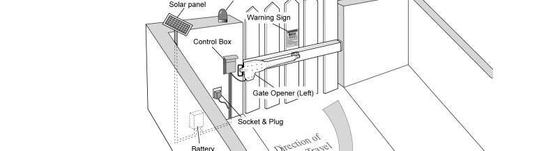
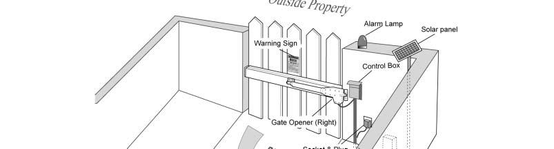
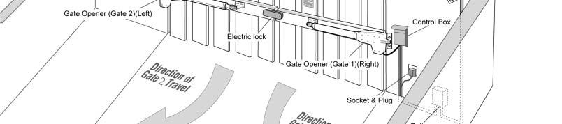
16 Mounting the Control Box Step 1 To install the control box use the deck screws (not provided). Ensure the control box is installed in a secure surface and at least 100 cm (40 inches) above the ground to protect it from rain, snow, etc. which probably cause damage to the control box. Warning: Before connecting the AC power cable to the control box, check the plug of power cable is disconnected from AC power socket. Step 2 Insert the power cable and cable of the first gate opener through the front strain relief and into the control box by loosening the strain relief screw located in the leftmost of outside bottom of the control box and feeding the cables into the control box. Check the length of cables is long enough to their respective terminal block in control box. Retighten the sealing nut so that cables are well locked. CAUTION: Install the Control Box in a well ventilated place protected against rain and sunlight. NOTE: It is strongly suggested that the control box should be mounted in the side of Master Gate (Gate 1), so that the electric lock can be installed correctly and work properly (See Page 9). 15


17 Step 3 Insert the cable of the second gate opener and alarm lamp cables into the control box through middle strain relief. Then repeat step 2. Step 4 Insert other cables into the control box through rightmost strain relief. Then repeat step 2. NOTE: Only motor cables (1.5m length) are provided. Other cables are subject to site installation requirement and not provided. CAUTION: Make sure the cable outlet hole in the Control Box is always down during installation so as to drain off the water. 16

18 Connecting of the control board ` 17
19 Actuator 1 Insert the stripped cable wires into the appropriate terminals on the opener terminals block. The red thick wire should be inserted into the MOTOR1+ terminal, the black thick wire into MOTOR1-, the thin red wire into ULT1, the thin black wire into COM, and the thin yellow wire into DLT1 terminal. Actuator 2 Similar as the connection of Actuator 1, insert the stripped cable wires into the appropriate terminals on the opener terminals block. The red thick wire should be inserted into the MOTOR2+ terminal, the black thick wire into MOTOR2-, the red wire into ULT2, the black wire into COM, and the yellow wire into DLT2 terminal. NOTE: It is recommended that Gate Opener 1 is installed in the Master Gate, and Gate Opener 2 is installed in the Slave Gate. Alarm Lamp (optional) The red wire of the alarm lamp should be inserted into either LAMP (#11) terminal, the white wire into the other one (#12). Back-up Battery (optional) The 24V+ of the battery should be wired to the BAT+ (#13) terminal, 24V- should be wired to BAT- (#14) terminal. Photocell Beam System (PBS) (optional) Use a 2-core cable to connect the - ~ terminal of the photocell s emitter to the 14 terminal, the + ~ terminal to the 9 terminal. Also the - ~ and + ~ terminals of the photocell s receiver should be connected to the 16 and 17 terminals in parallel. Use another 2-core cable to connect the COM terminal of the receiver to the 17 terminal, the NC terminal to the 18 terminal. Push Button (optional) The red wire should be inserted into either O/S/C terminal, the white wire into the other one. Loop Detector (optional) First insert the LOOP DETECTOR BOARD into the CONTROL BOARD, and then connect the twisted-pair to the LOOP terminal. Electric Lock (optional) The electric lock should be wired to the LOCK terminal. External Receiver (optional) The BROWN wire of the external receiver should be connected into the 19 terminal. The BLACK wire of the external receiver should be connected into the 20 terminal. The RED wire of the external receiver should be connected into the 9 terminal. Wired Keypad (24VDC) (optional) The RED wire of the wired keypad should be connected into the 9 terminal. 18
 Please refer to the manual instruction of solar panel and controller separted.")
20 The BLACK wire of the wired keypad should be connected into the 14 terminal. The WHITE wire of the wired keypad should be connected into the 19 terminal. The BLUE wire of the wired keypad should be connected into the 20 terminal. Solar Panel (optional) Please refer to the manual instruction of solar panel and controller separted. How to learn or erase the remote Learn the remote Press and release the learn button, the LED will display Ln, then press the key in the remote twice in 2 seconds, the LED will flash Ln for 4 seconds then back to - -. Now the remote has been learnt successfully. WARNING: Activate the opener only when gate is in full view, free of obstruction and properly adjusted. No one should enter or leave gate area while gate is in motion. Do not allow children to operate push button or remote. Do not allow children to play near the door. Your swing gate opener receiver and remote control transmitter are set to a matching code. If you purchase additional remote controls, the gate opener must be programmed to accept the new remote code. Erase all the remote codes Press and hold the learn button until the LED display back to - -. Now all remote codes have been erased. Caution: If you lose one of any remote control, please learn all other remote controls to have a new code for safety. 19

21 Setting of the Control Board ` 1. Check again for completed and correct assembly of your swing gate opener and gate. Plug the Power Grounded Cord into the nearest AC outlet. The Digital Display on the Control Board will flash with - -. The unit is in standby. 2. Single/Dual Gate Set Press and hold the FUNC button for more than 4 seconds. The Digital Display will indicate P1. Gate opener is on the SINGLE/DUAL Gate setting. Press the INC and DEC buttons respectively to following modes: 01 shown in Digital Display, it is Single Actuator 1 (Gate 1) mode. 10 shown in Digital Display, it is Single Actuator 2 (Gate 2) mode. 11 shown in Digital Display, it is Dual actuator mode. Press the FUNC button to store the data when the single or dual gate is chosen. The Digital Display will indicate P2. Now single/dual gate set is finished. (Factory set is 11 ) 3. Master/Slave Gate Set When Digital Display indicates P2, the gate opener is on the Master/Slave Gate Setting. Press the INC and DEC Buttons respectively to follow modes: 01 shown in Digital Display, which means Gate Opener 1 (right-hand side) as Master one 10 shown in Digital Display, which means Gate Opener 2 (left-hand side) as Master one Press the FUNC button to store the data when the master/slave gate is chosen. The Digital Display will indicate P3. Now Master/Slave Gate Set is finished. (Factory set is 01 ) 4. Set the Open Interval between Master and Slave Gate When the Digital Display indicates P3, the gate opener is on the Open Interval between Master/Slave Gate Setting. The open interval can be adjusted by pressing the INC and DEC Buttons respectively. The Digital Display will show 0-9, which indicates the interval time 0 means the Master and Slave gates open simultaneously. 1 means the Master Gate starts to open 1 second before Slave gate starts to open. Max. open interval is 9 seconds. Each time you press and release the INC button, the figure increases by 1, and the Master gate starts to open 1 more second earlier. Each time you press and release the DEC button, the figure decreases by 1, and the interval decreases by 1 second. (Factory set is 3 seconds) Press the FUNC button to store the data when the open interval is set. The Digital Display will indicate P4. Now Open Interval Set is finished. 5. Set the Close Interval between Master and Slave Gate When the Digital Display indicates P4, the gate opener is on the Close Interval between Master/Slave Gate Setting. The close interval can be adjusted by pressing the INC and DEC buttons respectively. The Digital Display will show 0-9, which indicates the interval time 0 means the Master and Slave gates open simultaneously. 1 means the Slave Gate starts to close 1 second before Master gate starts to close. Maximum close interval is 9 seconds. Each time you press and release the INC button, the figure increases by 1, and the Slave gate starts to close 1 more second earlier. Each time you press and release the DEC button, the figure decreases by 1, and the interval decreases by 1 second. 20
22 (Factory set is 3 seconds) Press the FUNC button to store the data when the close interval is set. The Digital Display will indicate P5. Now Close Interval Set is finished. 6. Adjust the Obstruction Sensitivity/Stall Force When the Digital Display indicates P5, the gate opener is on the Stall Force Adjustment. Without a properly installed safety reversal system, person (particularly small children) could be SERIOUSLY INJURED or KILLED by a closing gate. *Too much force on gate will interfere with proper operation of safety reversal system. *NEVER increase force beyond minimum amount required to close gate. *NEVER use force adjustments to compensate for a binding or sticking gate. * If one control (force or travel limits) is adjusted, the other control may also need adjustment. * After ANY adjustments are made, the safety reversal system MUST be tested. Gate MUST BE TESTED. Gate MUST reverse on contact with a rigid object. The opener is equipped with an obstruction sensing feature. If the gate encounters an obstruction the opener will automatically reverse direction and stop. Based on the length and weight of the gate it may be necessary to make force adjustments. The force adjustment should be high enough that small objects such as branches or wind will not cause nuisance interruptions but low enough to prevent serious injury to a person or a vehicle. 6-a Adjust Stall Force of Gate Opener 1 Now we adjust the stall force of gate 1 The stall force of gate opener1 is adjusted by pressing INC and DEC buttons respectively. The Digital Display will show 1-9 which indicates the stall force levels. 1 means the minimum force, and 9 is the maximum force. Each time you press and release the INC button, the figure increase by 1, and the force increases to a higher level. Each time you press and release the DEC button, the figure decreases by 1, and the force decreases to a lower level. Press FUNC to store the data. The Digital Display will indicate P6. Now stall force of gate opener 1 is finished. (Factory set is Level 3) 6-b Adjust Stall Force of Gate Opener 2 When the Digital Display indicates P6.you can adjust force of gate opener 2. Please perform the same procedure as gate opener 1 (6-a). Press the FUNC button to store the data when stall force of gate opener 2 is set. Then P7 will be shown on the Digital Display. NOTE: You may need to increase the stall force in cold weather due to increased resistance from gate hinges. The gate opener s opening/closing force is adjusted automatically according to stall force adjustment. 7. Adjust the Max Motor Running Time (MRT) of the MOTOR for gate opener The maximum running time of the MOTOR can be set to make the motor stop running after a specified period even if the limit switch is invalid or the clutch is detached. 7-a. Adjust the MRT of MOTOR1 When the Digital Display indicates P7, you can adjust the MRT of MOTOR1. The MRT of MOTOR1 is adjusted by pressing INC and DEC buttons respectively. The Digital Display will show which indicates the MRT of MOTOR1 from 1 to 50 seconds. You can hold pressing the INC or DEC button for more than 1 second to speed up the setting. Press the FUNC button to store the data when you finish setting. The Digital Display will indicate P8. (Factory default setting is 40 seconds) 21
23 7-b. Adjust the MRT of MOTOR2 When the Digital Display indicates P8, you can adjust the MRT of MOTOR2. Please perform the same procedure as adjusting MOTOR1 (7-a). Press the FUNC button to store the data when you finish setting. The Digital Display will indicate P9. Now MOTOR2 adjustment is finished. 8. Set the Safety Photocell Beam System (PBS) (Optional) When the Digital Display indicates P9, the gate opener enters PBS set mode. You can press and release the INC or DEC button to set or shut off the PBS function. The Digital Display indicates 11, the PBS is available. The Digital Display indicates 00, the PBS is null. Note: If the 11 is be set, the gate opener won t work until the PBS system is equipped. The PBS system works only when gate opener is closing. The gate opener will return to its open position when the obstruction blocks the beam from photo eye. Press the FUNC button to store the data when the PBS is set. The Digital Display will indicate PA. (Factory set is 00 ) 9. Set the Automatic Closing Time When the Digital Display indicates PA, the gate opener enters into the setting of automatic closing time mode. Press and release the INC or DEC button, the Digital Display will show a which indicates the current automatic closing time. The minimum time is 1 second, 99 seconds maximum. Each time you press and release the INC button, the figure increases by 1, and the timing increases by 1 second. Each time you press and release the DEC button, the figure decreases by 1, and the timing decreases by 1 second. When the timing is 00, the automatic closing function is shut off and the gate will stay open. (Factory set is 60 seconds) Press the FUNC button to store the data when the desired automatic closing time is set. The Digital Display will indicate Pb 10. Set the Period of Soft Start When the Digital Display indicates Pb, the gate opener is ready for setting period of soft start. You can press the INC or DEC button to set the period of soft start. There is 1-9 seconds available in setting. Press the FUNC button to store the data when the period is set. The Digital Display will indicate PC. (Factory set is 3 seconds) 11. Set the Fast Running Period (FRP) to Achieve Soft Stop Function (SPP) When the Digital Display indicates PC, the Fast Running Period for opening or closing gate is adjustable by pressing INC and DEC buttons respectively, and the Soft Stop Function is achieved simultaneously. The Soft Stop means the gate opener runs at slow speed during the last period before the gate completely closes. The Soft Stop Period is unavailable by direct adjust but available through adjusting the Fast Running Period. There are two running speeds designed in program, i.e. Fast Running Speed and Soft Running Speed. The Fast Running Period is adjustable from 1 to 28 sec. Factory default setting is 15 sec. Since the GATE OPENING OR CLOSING RUNING PERIOD (GRP) = SOFT START PERIOD (STP) + FAST RUNNING PERIOD (FRP) + SOFT STOP PERIOD (SPP), the SPP could be extended by shortening the FRP when the GRP and STP are fixed. In other words, SPP = GRP STP FRP. Similarly, the Soft Stop Period (SPP) can be shortened through extending the Fast Running Period (FPP). 22
24 Indicate Illustration on the Digital Display When Gate Opener is Running ` E.g. When the Soft Start Period (STP) is set at 3 sec, and the GRP is 23 sec, how can we get 4 sec of Soft Stop Period (SPP) to meet the requirement? The answer is clear, i.e. we may set the Fast Running Period (FRP) at 16 sec ( =16 sec). 12. Return to Factory Set When the Digital Display indicates Pd, press and release the INC or DEC button. All data will return to factory set, the Digital Display indicates df. 13. If all of data is set and no other change needed, press FUNC Button. - - appears on the Digital Display, and the opener enters standby mode. The left image on Digital Display symbolizes motor of gate opener 1 when the gate opener is running. The right image on Digital Display symbolizes motor of gate opener 2. When the motor is run to gate -open direction or gate -close direction, the image on Digital Display indicates n or u respectively. When the motor is not running, the Digital Display indicates - -. When Gate Opener 2 is set as Master gate (i.e. when 10 indicated at P2 set mode in the Control Board), the Digital Display flashes -n before the gate completely opens and closes. Adjusting the Limit Switch Step 13 Adjusting the Limit Switch of Actuator 1 Pull Gate 1 to its fully open position. Use a cross point screwdriver to loosen Limit Switch A and slide it to the desired position. Then fix the Limit Switch A. Pull Gate 1 to its fully closed position. Use a cross point screwdriver to loosen Limit Switch B and slide it to the desired position. Then fix the Limit Switch B. Limit setting for Gate 1 is finished. NOTE: Always place the magnetic ring between the Limit Switch A and B. Step 14 Adjusting the Limit Switch of Actuator 2 Perform similar procedures as in Step 13 to finish the Limit Setting for Gate 2. NOTE: Always place the magnetic ring between the Limit Switch C and D. Usually the Limit Switch A and C near the motors are factory adjusted. The user adjusts Limit Switch B and D as necessarily. The adjustment meets most users requirement on the stroke during gate 23

25 opening/closing. Shut OFF the power source first if the user needs to adjust the Limit Switch A and C. Turn ON the power after the adjustment. Allow the moving rod to automatically extend out, making sure the magnetic ring in the moving rod is always between both Limit Switches. NOTE: The magnetic ring in the moving rod can be manually placed between both Limit Switches in each actuator. See Page 23 Emergency Release. How to Operate The user may operate the opener once all adjustment setting is finished. With the gate in its closed position, press and release the remote control, the gate will move to the programmed opening position and stop. With the gate in its opened position, press and release the remote control, the gate will move to the programmed closing position and stop. While the gate is moving, press and release the remote control, the gate will stop moving immediately. The next command from the remote will reverse the gate direction and the gate will stop at its programmed opening/closing position. The gate will stop in case of obstruction during opening. The command from the remote control will reverse the gate direction and the gate will stop at its programmed closing position. The gate will reverse in case of obstruction or stall force during closing, and it will move to the programmed opening position. NOTE: The Obstruction Sensitivity /Stall Force is adjustable in 9 levels. Emergency Release In case of the system failure or power cut-off, the gate can be manually opened. Insert the triangular key inside the triangular plug located on the bottom of actuator body, and then turn clockwise (left actuator) or counter-clockwise (right actuator) till the stop. Motors shall be released. The inverse operation restores the gate automation. Installation for Push-to-Open Gates Ensure the gate does not open into public areas. In a Push-to-Open installation, gate opens out from the property. A Push-To-Open Bracket (PSO part) is required to be used for each gate. The gate is in the closed position during the opener is installed. Step 1 Place the PSO bracket between the two post brackets. Insert the M10x30 bolt through the center hole of the post bracket and PSO bracket as shown. Place a 10 washer, 10 lock washer and M10 nut on the bottom of the bolt and hand tighten. 24

26 Step 2 Attach the gate bracket and post bracket assembly to the opener by inserting a clevis pin. Secure the clevis pins using the hairpin clips. Step 3 With the gate in closed position and with the opener in their retracted position, place the opener with the gate bracket and post bracket assembly on to the gate post and the gate. Position the gate bracket and the post bracket assembly so that the gate opener is level with the horizontal cross member of the gate. While holding the opener in the desired level position, temporarily secure with two C-clamps. Step 4 to Step 9 Repeat the Step 4-9 in P Step 10 The motors power wires and limit wires connection by Push to Open is different from the connection by Pull to Open. So motor 1 and motor 2 wires should be connected to the control box as the instruction in the right, not according to the instructions in Page 17. Black thick wire should be inserted into the Motor+ terminal. Red thick wire should be inserted into the Motorterminal, the Yellow wire into ULT1 terminal and the Red wire into DLT1 terminal. Black wire is still into COM terminal. 25
27 Maintenance Warning: Disconnect power before servicing. 1. Using a clean, dry cloth, wipe the gate opener shaft, and then apply a silicone spray to reduce its friction. In cold climates where temperatures reach 1 C (30 F) or less, spray silicone on the actuator every 4~6 weeks to prevent freeze up. 2. Regularly check gate hinges to make sure gate is swinging smoothly and freely. Grease hinges if needed. 3. Check your installation periodically, as hardware and posts will shift. Brackets may need to be adjusted or hardware may need to be tightened. 4. Maintain the area around your gate. Keep the areas free of objects that can prevent the gate swinging freely. NOTES: 1. Inspection and service should always be performed anytime a malfunction is observed or suspected. 2. It is suggested that while at the site voltage readings be taken at the operator. Using a Digital Voltmeter, verify that the incoming voltage to the opener it is within ten percent of the opener s rating. 3. Refer to Page 20 for instructions on how to check gate force and sensitivity adjustments. Trouble Shooting 1. Opener does not run. Digital Display indicator is not on. Check if all motor are properly connected and color coded. Make sure the AC input is connected. Check if the fuse in control board is bad. 2. Opener powers up but does not run. Arm cable loose or disconnected. Verify that all of the wires going to the arm are secure and that the connector is properly mated to the header. Arm is incorrectly installed. Disconnect the motor housing from the arm and verify that the arm moves freely. Gate is excessively heavy or hinges are bad. Verify that the gate is within the ratings for this product. Disconnect the arms and verify that both gates swing easily. Lubricate or replace hinges as necessary. Bad control board. Call technical support for help with replacement parts. 3. Gate stops immediately after it starts moving. Obstruction sensed. Check safety devices and gate for obstructions. Force set too low. Adjust FORCE setting until gate completes a full open/close cycle without stop. The force setting may need to be adjusted in cold weather, as the gate will not move freely. Check if the TTC period is too short. Refer to page 19. Incorrect power. 4. Gate opens but does not close. Photocell (PBS) is set in Control Board but is not equipped (optional). Please cancel the PBS set. Refer to page 19. Obstruction blocking close photo eyes, Check eyes for alignment and verify all connections and operation for safety devices. 5. Gate ignores the limit switches Check that the limit switch is not faulty 26

28 Check that wires to the limit switch are not shorted. Ensure that the motor cable is away from sources of electrical interference, such as electric fences, power lines etc. 6. Gate opens, closes or stops on its own Ensure that the key for manual release is in the lock position. Refer to page 22. FCC Note: The manufacturer is not responsible for any radio or TV interference caused by unauthorized modifications to this equipment. Such modifications could void the user s authority to operate the equipment. This device complies with Part 15 of the FCC Rules. Operation is subject to the following two conditions: 1. This device may not cause harmful interference, and; 2. This device must accept any interference received, including interference that may cause undesired operation. 27
29 Quick-Setting Guide ` 28
30 29
31 30
32 31


33 32
34 S 220th St, Kent WA USA sales@wholesalegateopener.com LockMaster All Rights Reserved
Safety Installation Information Single Gate Opener Parts List...4. Dual Gate Opener Parts List...5. Technical Specifications & Features...
 Table of Contents ` Safety Installation Information..... 2-3 Single Gate Opener Parts List.........4 Dual Gate Opener Parts List........5 Technical Specifications & Features...........6-7 Installation
GENERAL SAFETY... 3 PARTS LIST...
 Rev 17a 1 GENERAL SAFETY... 3 PARTS LIST... 4 GTR100... 4 GTR058... 5 TECHNICAL SPECIFICATIONS... 6 FEATURES:... 6 QUICK INSTALLATION GUIDE... 7 GATE ARM INSTALLATION... 8 BEFORE YOU START... 8 INSTALLATION
SINGLE SWING GATE OPENER
 Thank you very much for choosing an Ironton product. For future reference, please complete the owner s record below: Serial Number/Lot Date Code: Purchase Date: Save the receipt, warranty and these instructions.
Table of Contents. General Safety Preparation for Installation Parts List Optional Accessories Part List... 5
 REV 12a Table of Contents General Safety....... 2 Preparation for Installation....... 3 Parts List....... 4 Optional Accessories Part List...... 5 Technical Specifications & Feature...... 5 Installation
Sliding Gate Opener User s Manual
 Gat Model: Sliding Gate Opener User s Manual GA2500 Gate1Access, LLC. www.gate1access.com Email: support@gate1access.com 1 Thank you for purchasing GA2500 gear rack drive sliding gate opener. We are sure
INSTALLATION M ANUAL
 INSTALLATION MANUAL Table of Contents UL Listings Installing the Warning Sign / Precautions Methods of Installation / Compact Installation Mounting the Secondary Entrapment / Welding Gate Arn Mounting
Eagle Access Control Systems, Inc. / (800) / (3)
 / (3)") UL Listings IMPORTANT SAFETY INSTRUCTIONS A. WARNING To reduce the risk of injury or death: 1) READ AND FOLLOW ALL INSTRUCTIONS. 2) Never let children operate or play with gate controls. Keep the remote
UL Listings IMPORTANT SAFETY INSTRUCTIONS A. WARNING To reduce the risk of injury or death: 1) READ AND FOLLOW ALL INSTRUCTIONS. 2) Never let children operate or play with gate controls. Keep the remote
AUTOMATIC GATE OPENER
 AUTOMATIC GATE OPENER Part # 7001282.001 Rev.A INSTALLATION MANUAL Model G752 For Double Gates AUTOMATIC GATE OPENER Installation Manual GATE OPENER CLASS CATEGORIES* The Zareba Automatic Gate Opener is
AUTOMATIC GATE OPENER
 AUTOMATIC GATE OPENER INSTALLATION MANUAL Model G750 For Single Gates AUTOMATIC GATE OPENER Installation Manual GATE OPENER CLASS CATEGORIES* The Zareba Automatic Gate Opener is intended for use with vehicular
Instruction Manual for the. E-SL 450 Series
 Instruction Manual for the E-SL 450 Series Estate Slide Summary of Functions The Estate Slide is only to be used for vehicular Slide gates in a Class I setting. Class I: A vehicular gate opener (or system)
Installation and Maintenance Manual
 Installation and Maintenance Manual Swing Gate Operator Model HL410-21 & HL410L-21 2 Contents Contents Parts & Components 3 Specifications & Capacities 4 Safety Information 6 Installer 6 End User 7 General
COMMERCIAL 24VDC HIGH TRAFFIC OVERHEAD DOOR AND GATE OPERATOR WITH BATTERY BACKUP INSTALLATION MANUAL
 COMMERCIAL 24VDC HIGH TRAFFIC OVERHEAD DOOR AND GATE OPERATOR WITH BATTERY BACKUP INSTALLATION MANUAL Model HCTDCU HCTDCU Motor Unit HCT08 8 Foot Rail HCT10 10 Foot Rail HCT12 12 Foot Rail THIS PRODUCT
Instruction Manual MB4 Rolling garage door opener
 Instruction Manual MB4 Rolling garage door opener INSTALLATION INSTRUCTIONS OWNERS COPY 1 WARNING: It is vital for the safety of persons to follow all instructions. Failure to comply with the installation
Owner s Manual. Model 9150 Vehicular Slide Gate Operator
 Owner s Manual Model 9150 Vehicular Slide Gate Operator DoorKing, Inc. 120 Glasgow Avenue Inglewood, California 90301 U.S.A. Phone: 310-645-0023 Fax: 310-641-1586 www.doorking.com P/N 9150-065 REV D, 5/07
Vehicular Swing Gate Operator. Nice. Titan 912L. The Titan 912L Gate Operator is intended for use with vehicular swing
 Vehicular Swing Gate Operator Nice Gate Operators Titan 912L The Titan 912L Gate Operator is intended for use with vehicular swing gates. The Titan 912L Gate Operator can be used in Class I, Class II and
LA412 & LA412-S O W N E R ' S M A N U A L 12 VOLT DC SINGLE SOLAR RESIDENTIAL GATE OPERATOR FOR RESIDENTIAL USE ONLY 2 YEAR WARRANTY
 LA & LA-S VOLT DC SINGLE SOLAR RESIDENTIAL GATE OPERATOR O W N E R ' S M A N U A L FOR RESIDENTIAL USE ONLY Please read this manual and the enclosed safety materials carefully! Periodic checks of the operator
R3 Roller Garage Door Opener
 R3 Roller Garage Door Opener INSTALLATION INSTRUCTIONS OWNERS COPY 1 WARNING: It is vital for the safety of persons to follow all instructions. Failure to comply with the installation instructions and
Actuator Arm and Control Box Mounting
 Actuator Arm and Control Box Mounting To wire this operator and complete the installation, refer to a specific control box Wiring/Owner s manual. 6002 Vehicular Swing Gate Operator 6002-065-Y-1-13 Copyright
PowerMaster MODEL MBG. Installation Manual U L R UL 325 AND UL 991 LISTED MEDIUM DUTY BARRIER GATE OPERATOR TABLE OF CONTENTS
 PowerMaster TABLE OF CONTENTS MODEL MBG MEDIUM DUTY BARRIER GATE OPERATOR Important Safety Information...... 3 System Designer Safety Instructions.......4 Installer Safety Instructions....... 5 Installation
AgriWheel Single Gate Kit Low Voltage & Solar. Installation & Operating Instructions
 AgriWheel Single Gate Kit Low Voltage & Solar Installation & Operating Instructions Thank you for purchasing you AgriWheel system. Please remove the lids from both the machine and control box and remove
Sliding Gate Operator User's Manual
 Sliding Gate Operator User's Manual PY800AC/PY00AC. Products introduction Please read the instructions carefully before proceeding. MCU is supplied to control the gate operator. Keypad / single button
SLIDING DOOR OPERATOR INSTRUCTION MANUAL
 SLIDING DOOR OPERATOR INSTRUCTION MANUAL (MODEL NO. 1071.101 & 1071.102) Please carefully keep this manual for good maintenance. Caution Be sure the door opener is far away from moisture, vibration, and
PowerMaster Model SG
 PowerMaster Model INSTALLATION MANUAL CAREFULLY READ THIS ENTIRE MANUAL FIRST BEFORE PROCEEDING! LEAVE THIS MANUAL WITH END USER FOR FUTURE REFERENCE AFTER INSTALLATION IS COMPLETE (LAST PAGE SHOULD BE
Sliding Gate Operator User's Manual
 Sliding Gate Operator User's Manual SL600AC. Products introduction Please read the instructions carefully before proceeding. MCU is supplied to control the gate operator. Keypad / single button interface.
115 VAC Control Boxes for
 CLASS 582 HP OPEN CLOSE Wiring / Owner s Manual Use this manual for circuit board 02-010 Revision A or higher. 115 VAC Control Boxes for 6002, 600, 600 and 600 gate operators 02-065-E-5-12 CFORMS TO ANSI/UL-25
Nice Apollo Swing Gate Opener
 Nice Apollo Swing Gate Opener Vehicular Swing Gate Operator Model T5ETL-1K Model T7ETL-1K Revision 1.0.0.0_2-2014 TABLE OF CONTENTS CAUTIONS AND NOTES 4 EXTREMELY IMPORTANT 4 ETL DEFINITIONS COMPLIANT
Thunder Power Tarp Kit Operation
 Thunder Power Tarp Kit Operation Dual Arm Curb Side Stowing Single Arm Curb Side Stowing 011-52476 Rev. H P a g e 2 In this booklet you will find: OPERATING INSTRUCTIONS... 3 Powering up or down the system...
GARAGE DOOR OPENER OWNER S MANUAL S3/S4
 GARAGE DOOR OPENER OWNER S MANUAL S3/S4 Features! Locking door during power failure: If power failure occurs while the door is operating, the door can be released by pulling the clutch down, allowing
Linear Actuator Swing Gate Operator Installation Manual Model # LA405-24
 Linear Actuator Swing Gate Operator Installation Manual Model # LA405-24 2 Contents Contents Product Information and Specs. 3 Mechanical 3 Electrical, Line Connections 3 Electrical, Control Connections
DOOR LIMITS A) ENGAGE CHAIN/BELT CONNECTOR TO CARRIAGE CAUTION B) CLOSE TRAVEL LIMIT
 ENGAGE CHAIN/BELT CONNECTOR TO CARRIAGE CAUTION B) CLOSE TRAVEL LIMIT") 20 6 DOOR LIMITS Severe injury or death can result if the door closing force is set too high. Never increase the door closing force above the minimum required to move the door. Never adjust force to compensate
20 6 DOOR LIMITS Severe injury or death can result if the door closing force is set too high. Never increase the door closing force above the minimum required to move the door. Never adjust force to compensate
MODEL MSW Medium Duty Swing Gate Operator
 INSTALLATION AND OWNER S MANUAL MODEL MSW Medium Duty Swing Gate Operator UL 325 and UL 991 Listed 22-1/4 16-1/2 19-1/2 16 20'' LENGTH X 14-3/4'' WIDTH 2 O.D. PIPE (BY OTHERS) Serial #: Date Installed:
Installing the gate post bracket with the cardboard arm template
 ......... Installing the gate post bracket with the cardboard arm template... Installing gate posts brackets and arms for Push-to-Open or Pull-to-Open gates... Connection of Power Source 240Vac or Solar...
115 VAC Control Boxes for
 CLASS MODEL SERIAL 58 HP CLOSE Wiring / Owner s Manual Use this manual for circuit board 0-010 Revision A or higher. EXTERNAL ENTRAPMENT PROTECTI MUST be installed or the gate operator WILL NOT function.
Installing the gate post bracket with the cardboard arm template
 ......... Installing the gate post bracket with the cardboard arm template... Installing gate posts brackets and arms for Push-to-Open or Pull-to-Open gates... Connection of Power Source 240Vac or Solar...
Nice Apollo Swing Gate Opener 1712/ VDC
 Nice Apollo Swing Gate Opener 1712/1812-12VDC Vehicular Gate Control Unit 1724/1824-24VDC Revision 1.0.0.0_02-2014 TABLE OF CONTENTS CAUTIONS AND NOTES 5 EXTREMELY IMPORTANT 5 ETL DEFINITIONS COMPLIANT
MODEL D-SBG Single Arm Barrier Gate Operator
 INSTALLATION AND OWNER S MANUAL MODEL D-SBG Single Arm Barrier Gate Operator UL 325 and UL 991 Listed WITH NITRO BOARD (SEE SUPPLEMENTAL MANUAL) Serial #: Date Installed: Your Dealer: READ THIS MANUAL
TABLE OF CONTENTS SAFETY SAFETY SYMBOL AND SIGNAL WORD REVIEW SAFETY 1 ACCESSORY WIRING 29 INTRODUCTION 5 EXPANSION BOARD 31 INSTALLATION 9
 TABLE OF CONTENTS SAFETY 1 SAFETY SYMBOL AND SIGNAL WORD REVIEW...1 USAGE CLASS...2 UL325 ENTRAPMENT PROTECTION REQUIREMENTS...2 SAFETY INSTALLATION INFORMATION...3 GATE CONSTRUCTION INFORMATION...4 INTRODUCTION
Sliding Gate Operator. User's Manual WARNING THIS PRODUCT MUST BE INSTALLED BY A QUALIFIED ELECTRICIAN
 Sliding Gate Operator User's Manual WARNING THIS PRODUCT MUST BE INSTALLED BY A QUALIFIED ELECTRICIAN BMG Imports Sliding Gate Opener MODEL No. LW550 Power rating: 220-240v AC 50Hz 550w Duty Close: 0-120
PY600AC Sliding Gate Opener User Manual
 PY600AC Sliding Gate Opener User Manual 2017 Dear users, Thank you for choosing this product. Please read the manual carefully before assembling and using it. Please do not leave out the manual if you
Nice Apollo Slide Gate Opener
 Nice Apollo Slide Gate Opener Vehicular Slide Gate Operator Model 72001K Revision 1.0.0.0_2-2014 TABLE OF CONTENTS CAUTIONS AND NOTES 4 EXTREMELY IMPORTANT 4 ETL DEFINITIONS COMPLIANT TO UL325 4 1 - OVERVIEW
Owner s Manual. Models 6050 and 6100 Vehicular Swing Gate Operators
 Owner s Manual Models 6050 and 6100 Vehicular Swing Gate Operators DoorKing, Inc. 120 Glasgow Avenue Inglewood, California 90301 U.S.A. Phone: 310-645-0023 Fax: 310-641-1586 www.doorking.com P/N 6050-065
FOR CLASS I, II, III, IV VEHICULAR GATE OPERATORS
 Ramset_Man300.qxd 4/18/05 1:06 PM Page 1 FOR CLASS I, II, III, IV VEHICULAR GATE OPERATORS Ramset_Man300.qxd 4/18/05 1:06 PM Page 2 www.ramsetinc.com Ramset_Man300.qxd 4/18/05 1:06 PM Page 3 TABLE OF CONTENTS
Nice Apollo Swing. Model 36001K. Vehicular Swing Gate Operator. Revision _2-2014
 Nice Apollo Swing Gate Opener Model 35001K Vehicular Swing Gate Operator Revision 1.0.0.0_2-2014 Model 36001K TABLE OF CONTENTS CAUTIONS AND NOTES 4 EXTREMELY IMPORTANT 4 ETL DEFINITIONS COMPLIANT TO
ONE TOUCH CONTROL BOX
 ONE TOUCH CONTROL BOX CONVERSION KIT INSTRUCTIONS REMOVAL, INSTALLATION, OPERATION, AND REMOTE CONTROL PROGRAMMING THUNDERSTONE PART #101322 REVISION A JULY 14 TH 2016 2 P a g e INSTALLING THE THUNDER
LA400 & LA400-S O W N E R ' S M A N U A L MEDIUM DUTY SWING GATE OPERATOR. Large Metal Control Box (XLM) Optional 2 YEAR WARRANTY
 Optional 2 YEAR WARRANTY") LA400 & LA400-S MEDIUM DUTY SWING GATE OPERATOR O W N E R ' S M A N U A L Large Metal Control Box (XLM) Optional Serial # Primary Arm Serial # Secondary Arm Serial # Control Box Installation Date The LA400
LA400 & LA400-S MEDIUM DUTY SWING GATE OPERATOR O W N E R ' S M A N U A L Large Metal Control Box (XLM) Optional Serial # Primary Arm Serial # Secondary Arm Serial # Control Box Installation Date The LA400
AUTOMATIC CONTROL ROLLING DOOR OPENER
 AUTOMATIC CONTROL ROLLING DOOR OPENER INSTALLATION INSTRUCTION AUTOMATIC OBSTRUCT PHOTOELECTRIC BEAM ROLLING CODE SYSTEM AUTO CLOSE DOOR ANTI-THEFT SYSTEM INSTALLATION INSTRUCTION AND RDO OWNERS MANUAL
Installation Manual for the. Automatic Gate Opener System FOR DUAL SWING GATES
 Installation Manual for the AUTOMATIC GATE OPENER Automatic Gate Opener System FOR DUAL SWING GATES WARNING! READ ALL INSTRUCTIONS CAREFULLY AND COMPLETELY before attempting to install and use this automatic
Roller Door Operator
 INSTALLATION INSTRUCTIONS AND OWNERS MANUAL Roller Door Operator IMPORTANT PLEASE READ THESE INSTRUCTIONS CAREFULLY PRIOR TO COMMENCING THE INSTALLATION OF THE OPERATOR UNIT CAUTION This Automatic Opener
SECTIONAL AND TILTING DOOR OPENER INSTALLATION INSTRUCTIONS AND USER GUIDE. Comfort 800E/1000E
 SECTIONAL AND TILTING DOOR OPENER INSTALLATION INSTRUCTIONS AND USER GUIDE Comfort 800E/1000E WARNING Please read the manual carefully before installation and use. The installation of your new door opener
AC Powered. AC Powered. Model Installation/Owner s Manual. UL 325 Compliant. AC Powered Vehicular Swing Gate Operator
 Installation/Owner s Manual Model 652-080 AC Powered Vehicular Swing Gate Operator Use this manual for circuit board 100-010 Revision AA or higher. EXTERNAL ENTRAPMENT PROTECTI MUST be installed or the
Unpack. Left Handing (L) the Operator. StrongArmPark DC Breakaway Bracket Installation Video
 the Operator. StrongArmPark DC Breakaway Bracket Installation Video") DC Left Handing (L) Standard. Factory ships left handing operator. NOTE: If your site requires right handing, place the order with your distributor as a StrongArmPark DC with right handing. Handing changes
DC Left Handing (L) Standard. Factory ships left handing operator. NOTE: If your site requires right handing, place the order with your distributor as a StrongArmPark DC with right handing. Handing changes
Solar Control Box for
 CLASS MODEL SERIAL 53382 HP CLOSE Wiring / Owner s Manual Use this manual for circuit board 4302-010 Revision N or higher. Solar Control Box for 6002, 6003, 6004 and 6400 gate operators 4302-067-N-2-13
HIGH SPEED SLIDING GATE OPENER
 HIGH SPEED SLIDING GATE OPENER Model: is1200 + Elsema s Eclipse Control Card with GDS Operator USER MANUAL CONTENTS Section No: Page No: 1 Safety Precautions 3 2 Wiring Requirements 4 3 Installation details
OWNER S MANUAL MODEL NO. MEDIUM DUTY JACK SHAFT OPERATOR MDJ, MDJH, MDJB, MDJBH READ AND FOLLOW ALL INSTALLATION INSTRUCTIONS SAVE THESE INSTRUCTIONS
 OWNER S MANUAL MEDIUM DUTY JACK SHAFT OPERATOR MODEL NO. NOT FOR RESIDENTIAL USE READ AND FOLLOW ALL INSTALLATION INSTRUCTIONS SAVE THESE INSTRUCTIONS This unit is intended for limited duty applications
Model 2300JL Installation Guide
 Model 2300JL Installation Guide POWER ACCESS CORPORATION 4 HERSHEY DRIVE, DOCK 4 ANSONIA, CT 06401 800-344-0088 WEBSITE: www.power-access.com EMAIL: salesinfo@power-access.com 1 STANDARD PARTS MODEL 2300JL
Model 2300DL Installation Guide
 Model 2300DL Installation Guide POWER ACCESS CORPORATION 4 HERSHEY DRIVE, DOCK 4 ANSONIA, CT 06401 800-344-0088 WEBSITE: www.power-access.com EMAIL: salesinfo@power-access.com 1 STANDARD PARTS MODEL 2300DL
Sectional and Tilting Door Opener
 Sectional and Tilting Door Opener Installation Instructions and User Guide 600 800 1000 S/N WARNING Please read the manual carefully before installation and use. The installation of your new door opener
Owner s Manual. Overhead Gate Operator. Copyright 2015 DoorKing, Inc. All rights reserved. REV SENSE OPEN GATE FORCED NO NC
 Owner s Manual 50 Overhead Gate Operator EXIT PART REVERSE TIME DELAY REV SENSE OPEN REV SENSE CLOSE 2 3 4 5 6 7 8 2 3 4 PUSH TO OPERATE technician use only GATE FORCED NO NC Copyright 205 DoorKing, Inc.
Owner s Manual. Model 9300 Vehicular Slide Gate Operator
 Owner s Manual Model 9300 Vehicular Slide Gate Operator DoorKing, Inc. 120 Glasgow Avenue Inglewood, California 90301 U.S.A. Phone: 310-645-0023 Fax: 310-641-1586 www.doorking.com P/N 9300-065 Rev C 6/03
Installation/Owner s Manual
 CLASS MODEL SERIAL HP 53382 DoorKing, Inc., Inglewood, CA Installation/Owner s Manual Use this manual for circuit board 4502-010 Revision K or higher. For operators manufactured July 2011and later. Series
115 VAC Control Boxes for
 CLASS MODEL SERIAL 8 HP DOORKING CLOSE Wiring / Owner s Manual Use this manual for circuit board 0-00 Revision AA or higher. EXTERNAL ENTRAPMENT PROTECTI MUST be installed or the gate operator WILL NOT
Installation/Owner s Manual Series 9500
 MOVING GATE CAN CAUSE SERIOUS INJURY OR DEATH Operate gate only when gate area is in sight and free of people and obstructions. Do not allow children to play in gate area or operate gate. Do not stand
Owner s Manual. Model 9100 Vehicular Slide Gate Operator
 Owner s Manual Model 9100 Vehicular Slide Gate Operator DoorKing, Inc. 120 Glasgow Avenue Inglewood, California 90301 U.S.A. Phone: 310-645-0023 Fax: 310-641-1586 www.doorking.com P/N 9100-065 REV C, 1/04
SKC400U SLIDING GATE OPENER OWNER S MANUAL
 SKC400U SLIDING GATE OPENER OWNER S MANUAL IMPORTANT SAFTEY INFORMATION Installing the SKC400U Gate Opener requires wiring of standard 110V electrical lines. This should only be performed by a trained
Owner s Manual. Series 6050 and Vehicular Swing Gate Operator. Copyright 2010 DoorKing, Inc. All rights reserved. WARNING
 CERTIFIED TO CAN/CSA C22.2 NO. 247 53382 VEHICULAR GATE OPERATOR CLASS HP MODEL SERIAL AMPS 60 Hz MAX GATE LOAD DoorKing, Inc., Inglewood, CA MOVING GATE CAN CAUSE SERIOUS INJURY OR DEATH Operate gate
MODEL D-WBG Wishbone Arm Barrier Gate Operator
 INSTALLATION AND OWNER S MANUAL MODEL D-WBG Wishbone Arm Barrier Gate Operator UL 325 and UL 991 Listed WITH NITRO BOARD (SEE SUPPLEMENTAL MANUAL) Serial #: Date Installed: Your Dealer: READ THIS MANUAL
PowerMaster. Installation Manual UL 325 AND UL 991 LISTED MODEL RSG TABLE OF CONTENTS
 MODEL RSG RESIDENTIAL SLIDE GATE OPERATOR TABLE OF CONTENTS PowerMaster Installation Manual RESIDENTIAL SLIDE GATE OPERATOR UL 325 AND UL 991 LISTED UL R Important Safety Information.....3 UL Installation
Thunder Power Tarp Kit Operation. Dual Arm Curb Side Stowing Single Arm Curb Side Stowing Flex Arm Curb Side Stowing.
 Thunder Power Tarp Kit Operation Dual Arm Curb Side Stowing Single Arm Curb Side Stowing Flex Arm Curb Side Stowing 011-52475 Rev - 2 P a g e USE THE PROCEDURES BELOW TO OPERATE THE TARP SYSTEM Powering
Sectional And Tilting Door Opener
 Sectional And Tilting Door Opener Installation Instructions and User Guide FS 600 FS 1000 FS 1200 600N 1000N 1200N FS 600-Speed FS 1000-Speed 600N 1000N S/N WARNING Please read the manual carefully before
GARAGE DOOR OPERATOR USER S MANUAL
 GARAGE DOOR OPERATOR USER S MANUAL - DOMESTIC USE CIL-CD800S Chain) CIL-BD800S Belt GARAGE DOOR OPENER OWNER S MANUAL - DOMESTIC USE CIL-CD800S CD800S(Chain Chain) CIL-BD800S BD800S(Belt Belt) 1 Features
Model 1550 Single Swing Gate Model 1650 Dual Swing Gate
 Gate Operators, Inc. Model 1550 Single Swing Gate Model 1650 Dual Swing Gate Swing Gate Operator CONTENTS Safety Precautions... 2 Applications... 3 Pre-Installation Checklist... 4 Parts Identification...
Installation Manual SINGLE GATE SYSTEM
 -800-543-GATE (483) www.mightymule.com Can Cause Injury or Death Installation Manual E-Z GATE OPENER 500 UL35 SERIES C L I S T E D US E-Z GATE OPENER 500! WARNING MOVING GATE SINGLE GATE SYSTEM! WARNING
ontrol Systems, Inc. Swing Gate Installation Manual Eagle-200 Series Eagle-100 Series UL325 and UL991 Compliant
 Swing Gate Installation Manual Eagle-200 Series Eagle-100 Series ontrol Systems, Inc. www.eagleoperators.com Operator installation and instructions for the Eagle-200 and Eagle-100 Series. UL325 and UL991
Solar Control Box for
 CLASS MODEL SERIAL 5338 HP D OOR KIN G OPEN CLOSE Wiring / Owner s Manual Use this manual for circuit board 430-010 Revision AA or higher. EXTERNAL ENTRAPMENT PROTECTI MUST be installed or the gate operator
Gate Operators, Inc. Model 7100UL Residential & Medium Duty Commercial Slide Gate Operator INSTALLATION MANUAL
 Gate Operators, Inc. Model 7100UL Residential & Medium Duty Commercial Slide Gate Operator INSTALLATION MANUAL 10-04-00 CONTENTS Safety Precautions... 2 Applications... 3 Pre-Installation Checklist...
DKC400Y AC Sliding Gate Installation Manual. Sliding Gate Opener. Model: DKC400Y. Installation Manual WARNING
 Sliding Gate Opener Model: DKC400Y Installation Manual WARNING Read and thoroughly understand all instructions before installing or operating this automatic gate opener. Failure to do so may cause serious
INSTALLATION MANUAL MODEL LA412 RESIDENTIAL DC SOLAR VEHICULAR SWING GATE OPERATOR. UL991 compliant. UL325 compliant. LA4121PKGDC Single Arm Package
 RESIDENTIAL DC SOLAR VEHICULAR SWING GATE OPERATOR MODEL LA412 LA4121PKGDC Single Arm Package LA412DC Primary 12 VDC Actuator Arm for single swing gate applications LA412DCS Secondary 12 VDC Actuator Arm
Installation/Owner s Manual Series 6500
 Installation/Owner s Manual Series 00 Use this manual for circuit board 0-00 Revision E or higher. EXTERNAL ENTRAPMENT PROTECTI MUST be installed or the gate operator WILL NOT function. Vehicular Swing
UGP-712 Vehicular swing gate operator
 Vehicular swing gate operator INSTALLATION INSTRUCTION MANUAL PLATINUM ACCESS SYSTEMS Installation Instructions & Safety Information Manual Vehicular Swing Gate Operator Class I, Class II, Class III, and
COOKSON OWNER S MANUAL
 COOKSON OWNER S MANUAL ELECTRIC CLUTCH RELEASE FOR TUBULAR MOTOR 3117(1) ECN 0951 BY RG 10/28/10 1 PATENT NO. 6,155,324 SPECIFICATIONS ELECTRICAL SPECIFICATIONS TUBULAR MOTOR FOR TUBULAR MOTOR ELECTRICAL
Letron Auto Gates (Australia) Pty. Ltd. User s Installation Manual
 Pty. Ltd. User s Installation Manual") Letron Auto Gates (Australia) Pty. Ltd. User s Installation Manual Sliding Gate Motor AUTOMATIC OBSTRUCT PHOTO ELECTRIC BEAM ROLLING CODE SYSTEM AUTO CLOSE DOOR SOLAR COMPATIBLE ( DC ONLY ) Model SL810
Letron Auto Gates (Australia) Pty. Ltd. User s Installation Manual Sliding Gate Motor AUTOMATIC OBSTRUCT PHOTO ELECTRIC BEAM ROLLING CODE SYSTEM AUTO CLOSE DOOR SOLAR COMPATIBLE ( DC ONLY ) Model SL810
Sectional and Tilting Door Opener Installation Instructions and User Guide
 Sectional and Tilting Door Opener Installation Instructions and User Guide ET-600E ET-800E ET-1000E S/N WARNING Please read the manual carefully before installation and use. The installation of your new
IQ Gate Systems. IQ-500 Installation And Instruction Manual UL 325 and UL 991 Compliant.
 IQ Gate Systems IQ-500 Installation And Instruction Manual www.iqgatesystems.com 1-801-455-7961 UL 325 and UL 991 Compliant Revision B IQ Gate Systems: IQ-500 Installation IQ-500 Capacities: Swing gates
Installation/Owner s Manual
 CLASS MODEL SERIAL HP 53382 Read owner s manual and safety instructions. Installation/Owner s Manual Use this manual for circuit board 4502-010 Revision AA or higher. EXTERNAL ENTRAPMENT PROTECTI MUST
SWING GATE OPENERS 24V DC GEAR MOTOR
 SWING GATE OPENERS 24V DC GEAR MOTOR FOR RESIDENTIAL USER MANUAL Flashing Light Push Button Control box Gate 2 Gate 1 Index 1. Warnings 2 4. Technical Characteristics 16 2. Product Description 2.1 Applications
RESIDENTIAL DC VEHICULAR SWING GATE OPERATOR
 RESIDENTIAL DC VEHICULAR SWING GATE OPERATOR INSTALLATION MANUAL Model RSW12U THIS PRODUCT IS TO BE INSTALLED AND SERVICED BY A TRAINED GATE SYSTEMS TECHNICIAN ONLY. This model is for use on vehicular
6002 swing gate actuator - installation guide
 600 swing gate actuator - installation guide 600 Residential Swing Gate Actuator Installation Guide DKS DoorKing, Inc. 0 Glasgow, Avenue Inglewood, Ca. 900 0.645.00 0.64.586 fax info@doorking.com www.doorking.com
RAMSET
 RAMSET TABLE OF CONTENTS Important Safety Requirements & Instructions...1 Responsibilities of Installers and Technicians...2 Important Safety Requirements by UL Standards...3 Classes of Vehicular Gate
Installation Manual. Post Bracket Assembly. Gate Bracket. 12 Volt automotive or marine type battery in weather proof housing (not included).
.") Installation Manual MM360 Receiver Gate Swings Evenly and Freely Hung Firmly and Plumb Warning Sign Post Bracket Assembly Single Gate Opener 120 Volt indoor Transformer (surge protector not supplied) Gate
Installation Manual MM360 Receiver Gate Swings Evenly and Freely Hung Firmly and Plumb Warning Sign Post Bracket Assembly Single Gate Opener 120 Volt indoor Transformer (surge protector not supplied) Gate
gate operator class categories and examples
 BLSL840 Manual_Layout 1 3/14/2014 4:06 PM Page 1 BLSL840 BLSL840 Manual_Layout 1 3/14/2014 4:06 PM Page 2 BLSL840 Manual_Layout 1 3/14/2014 4:06 PM Page 3 Installation Instructions & Safety Information
DIAMOND. Installation Manual. DUAL Gate Operator System
 Installation Manual DIAMOND DUAL Gate Operator System WARNING! This equipment is similar to other gate or door equipment and meets or exceeds Underwriters Laboratory Standard 325 (UL 325). However, gate
TABLE OF CONTENTS SAFETY SAFETY SYMBOL AND SIGNAL WORD REVIEW SAFETY 1 OPERATION 31 INTRODUCTION 5 ACCESSORY WIRING 34 INSTALLATION 9 MAINTENANCE 36
 TABLE OF CONTENTS SAFETY 1 SAFETY SYMBOL AND SIGNAL WORD REVIEW...1 USAGE CLASS...2 UL325 ENTRAPMENT PROTECTION REQUIREMENTS...2 SAFETY INSTALLATION INFORMATION...3 GATE CONSTRUCTION INFORMATION...4 INTRODUCTION
copyright 2008 chamberlain professional products -
 copyright 2008 chamberlain professional products - www.liftmaster.com TABLE OF CONTENTS Role of Specifiers and Designers Role of Dealers, Installers and Trained Gate System Technicians Role of End Users
Installation/Owner s Manual Series 6500
 Installation/Owner s Manual Series 00 Use this manual for circuit board 0-08 Revision A or higher. Vehicular Swing Gate Operator Entrapment Protection must be provided for the gate system where the risk
Installation Manual for the. Automatic Gate Opener System for Single Swing Gates Only
 Installation Manual for the 250 E-Z GATE OPENER UL325 SERIES 1-800-543-GATE (4283) www.mightymule.com Automatic Gate Opener System for Single Swing Gates Only WARNING! This equipment is similar to other
For Classes I, II, III, IV
 For Classes I, II, III, IV pg 1 Contents Pg. General Information...3 Features...5 Parts Identification...6 Installation...8 Alternate Installation...12 Electrical...13 Fine Tuning...17 Master and Slave...18
Owner s Manual. Series 6300 Vehicular Swing Gate Operators
 Owner s Manual Series 6300 Vehicular Swing Gate Operators DoorKing, Inc. 120 Glasgow Avenue Inglewood, California 90301 U.S.A. Phone: 310-645-0023 Fax: 310-641-1586 www.doorking.com P/N 6300-065 REV E,
User manual. e-gate SLD-24V
 User manual FOR e-gate SLD-24V 24V Sliding Gate Operators Contents how to use your automatic gate operator...... 1 how the controls work.................. 2 how to manually release the gate...........
Tooling Assistance Center
 Safeguards are designed into this application equipment to protect operators and maintenance personnel from most hazards during equipment operation. However, certain safety precautions must be taken by
IMPORTANT SAFETY RECOMMENDATIONS
 - 1 - - 2 - IMPORTANT SAFETY RECOMMENDATIONS FAILURE TO COMPLY WITH THE FOLLOWING SAFETY RECOMMENDATIONS MAY RESULT IN SERIOUS PERSONAL INJURY, DEATH AND/OR PROPERTY DAMAGE The installation of the Automatic