Instruction Part #90577
|
|
|
- Junior Bennett Dawson
- 5 years ago
- Views:
Transcription

1 Phantom Key Push Button Ignition System Instruction Part #90577 For Installing: Part # s 55000, 55001, 55002, 55003, 55004, & Perfect Performance Products, LLC Painless Performance Products Division 2501 Ludelle Street Fort Worth, TX phone fax Web Site: painless@painlessperformance.com
2 If you have any questions concerning the installation of this harness or having trouble after the installation, feel free to call Painless Performance Products' tech line at Calls are answered from 8 am to 5 pm central time, Monday thru Friday, except holidays. We have attempted to provide you with as accurate instructions as possible, and are always concerned about corrections or improvements that can be made. If you have found any errors or omissions, or if you simply have comments or suggestions concerning these instructions, please write us at the address above. Or, better yet, send us a fax at (817) or us at painless@painlessperformance.com. We sincerely appreciate your business. Perfect Performance Products, LLC shall in no event be liable in contract or tort (including negligence) for special, indirect, incidental, or consequential damages, such as but not limited to, loss of property damage, or any other damages, costs or expenses which might be claimed as the result of the use or failure of the goods sold hereby, except only the cost of repair or replacement. June 2011 Copyright 2011 by Perfect Performance Products, LLC 2
3 A full color copy of these instructions can be found at Painless Performance Products recommends you, the installer, read this installation manual from front to back before installing this harness. Reading thoroughly before any installation takes place will give you insight on the proper installation of this harness. Please be aware that you are dealing with high amperage connections at the ignition switch, be certain the appropriate connections to the Phantom Key module are made. There should be no guessing, incorrect connections could lead to module and ignition system failure. Factory schematics of the starting system and ignition switch will be greatly useful in connection of this Painless product. They will make understanding each wire function easier and will save you a lot of time that would otherwise be used trying to identify wires at the ignition switch with a volt meter. These schematics can be located on the internet and in vehicle specific manuals sold in most auto parts stores. If schematics cannot be located, a call to the Painless tech department could lead to you getting the information you need. While we have access to hundreds of different vehicle schematics, your particular vehicle may not be one in our library. Also, please take notice that the tech department can be very busy at times and to make it easier for you and the tech, know the color of the wires and the location of them on your ignition switch before calling. Contact one of the Painless techs at (800) The colors used on the Phantom Key are GM color-coded. Meaning if your vehicle is a GM product, if the chassis harness used in your vehicle is an aftermarket GM color-coded harness, or if you have an aftermarket GM style column with an ignition switch, the wires of the Phantom Key should match the colors of the wires you will be connecting to. 3
4 TABLE OF CONTENTS PAGE # SECTION 5 INTRODUCTION 6 CONTENTS OF THE PAINLESS KIT 8 TOOLS NEEDED 9 PRE-INSTALLATION GUIDELINES 10 INSTALLATION 11 Push button Mounting 12 Module & Relay Mounting 13 Harness Connections 24 KEY FOB MODES, INFORMATION, & OPERATION 25 TESTING THE INSTALLATION 26 PROGRAMMABLE MODES 28 Key Fob Learn 29 Emergency Bypass DIAGRAMS 15 QUICK CONNECT METHODS 16 CONNECTORS 17 WIRE FUNCTIONS 20 GM COLUMN MOUNTED IGNITION SWITCH 22 RELAYS 4
5 INTRODUCTION The contents of this product include everything needed to replace the function of a keyed ignition switch with a simple push button. From entry-level vehicles to high-end exotics, this same push button feature can be found on many of today s newer cars. By carefully working your way through this instruction manual, you will be able to retro fit your classic or modern vehicle with some of today s new vehicle technology. The Phantom Key module completely eliminates your vehicles ignition switch and allows the operator of the vehicle to operate the ON and START functions with the simple push of a button. The key fob communicates with the Phantom Key module as you approach or walk away from the vehicle. RFID technology allows the push button ignition switch to operate only for the owner/user of the vehicle. Simply carry one of the key fob IDs with you, as you come into proximity of the vehicle with the Phantom Key installed, the module verifies your ID, and becomes active allowing the push button to work. This proximity is about 10 feet. In the same sense, when the key fob ID moves out of the proximity of the vehicle the module becomes inactive, and the push button does not operate. See the PROGRAMMABLE MODES portion of this manual for details on automatic and manual modes of identification from the key fob. Each key fob ID is unique so a key fob from another Phantom key system will not work with the module found in your Phantom key kit unless it is programmed to your module. See the PROGRAMMABLE MODES portion on this manual for details. This assures you, the end user, that the security of your vehicle with the Phantom key system installed cannot be compromised. However, a single key fob can be programmed to multiple vehicles allowing someone to operate their car, truck, boat, RV, etc all with one key fob if each vehicle has a Phantom key module installed. This install manual is broken down into sections: Introduction - provide simple clarification of the Phantom Key Product Contents of the Painless Kit lists parts your Phantom Key Kit supplies Tools Needed - lists all things required to properly install the Phantom Key Pre-Installation Guidelines contains precautions to take into account before installation beings and basic install information Installation- walks you through installing the complete system step by step Key Fob Modes & Information- outlines the 2 different ways the key fobs communicate and specifics of the key fobs Testing- details the proper test sequence of a new install Programmable Modes walks you through the customizable features of the Phantom Key, programming new key fobs, and the Emergency function To avoid possible mistakes and damage to the module, follows these instructions from one page to the next and do not skip around. There are some steps that must be completed before others. 5
6 CONTENTS OF THE PAINLESS KIT Refer to the Contents Figure (below) to take inventory. See that you have everything you are intended to have in this kit. If you find that anything is missing or damaged, please contact the dealer where you obtained the kit or Painless Performance at (800) The Painless Wire Harness Kit should contain the following: (1) PHANTOM KEY MODULE with HARNESS and RELAY BANKS (1) PUSH STAINLESS PUSH BUTTON with EXTENSION HARNESS (1) SMALL MOMENTARY BUTTON (1) PHANTOM KEY ID CARD (2) KEY FOBS (4) RELAYS (5) SELF TAPPING SCREWS (4) 4 STRIPS OF VELCRO (50) ZIP TIES (1) SMALL PARTS KIT- contains relays, splices, heat shrink, and terminals CONTENT FIGURE- All of the parts in the Painless kit 6

7 SMALL PARTS Included with the Painless harness is a parts kit containing insulated ring terminals. These terminals have a semi-transparent insulation that is heat shrinkable to provide a weatherproof connection. The un-insulated splices are to be used in conjunction with the supplied heat shrink. These will be used when splicing into the power wires at the ignition switch The blue Posi-Taps contained in the parts kit make connection quick and easy without any cutting involved to the wires of your existing harness. Unlike traditional blade style taps, which usually cut through the wire you are tapping onto, the Posi- Tap, simply pierces the insulation. Proper installation of the Posi-Tap can be accomplished in 4 easy steps: 1. Slide the slotted end over the wire/power source you are tapping onto. This will be a pre-existing wire, not a wire found in the Painless kit. 2. Thread the main body of the Posi- Tap onto the slotted end, ensuring the needle pierces the wire. Smaller gauge wires tend to move aside as the needle comes down, causing improper connections. Watch closely to ensure this does not happen. 3. Strip a ¼ of insulation away from the wire you are connecting. This will be a wire coming from the Phantom Key harness. 4. Insert the stripped wire into the small threaded end, and then thread it into the Posi-Tap main body. There are 2 different types of relays found in the parts kit, although they look identical except for the print on them. The difference and which relay bases require the correct relays is detailed on p.14 of this manual. The lock and unlock relays will not function correctly unless the correct relays are installed. 7


8 TOOLS NEEDED In addition to your regular hand tools, you will need, at least, the following tools: Wire Crimping and Stripping Tools: This style of hand crimper can be purchased from just about any local auto parts store, home improvement store or can also be purchased online. You will need this style of crimper to crimp the heat shrinkable insulated ring terminals included in the small parts kit. A good set of wire strippers are required. This style of wire stripper is ideal for this harness install because of its ability to properly strip wire gauges 10 to 20. These are available from just about any local auto part store, electrical supply shop, home improvement store or can be purchased online. Volt/Ohm Meter: A Volt/Ohm meter is always a good tool to have on hand when installing any type of electrical components into any vehicle. Most basic units provide the two functions required to diagnose electrical issues seen during a harness install. These two functions are the ability to read DC Voltage and electrical continuity or Ohms. They can be purchased from any home improvement store, local hardware store, and electrical supply shop and online. Electric Drill & Bits: A drill and bits are needed in order to use the screws provided with the kit to mount the module and relay. Heat Gun: Very useful to shrink the heat-shrinkable terminals found in the parts kit as well as the heat shrink. Factory Wire Schematic This isn t necessary; however, having one handy is good practice with any electrical job. Chilton s and Haynes manuals, which can be found at most auto parts stores and online, usually contain these schematics. Soldering Iron This isn t necessary; however it will provide more positive connections to the large amperage wires of the ignition switch connections over the splices provided in the kit. 8
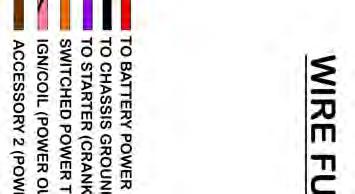
9 PRE-INSTALLATION GUIDELINES At this time identify the wires of the chassis harness you will be connecting to. A factory schematic and/or a voltmeter will help accomplish this. You may find that there are extra wires going to your ignition switch that the Phantom key does not support. In most causes these are ground wires to key buzzers and indicator lights in the dash. At the ignition switch the Phantom Key module will need to connect to 3 or more sources: Battery Power- This will be the wire that feeds power from the battery to the switch Switched Power- This will be the wire(s) from the switch that provide power to the fuse block. There could be one or more of these wires depending if you have an ACCESSORY position as well as the ON/RUN position. Some ignition switches also provide power to the ignition system or coil. Start- This wire provides power out to the clutch safety/neutral safety/starter solenoid when the ignition switch is in the START position. At the headlight switch or at an exterior parking light the Phantom Key will need to connect to one source: Park Light Power- This will be the wire that provides power from the headlight switch out to the Park/Tail lights. At the brake switch, turn signal switch, or brake light the Phantom Key will need to connect to one source: Brake Light Power- This will be the wire supplies power to the brake lights when the brake pedal is pressed. Depending on how your door locks are activated you will be making ground connections from the Phantom Key to your lock/unlock module or to the lock/unlock switches, or those that switch power will be connecting power to the lock/unlock switches or to the lock/unlock solenoids themselves. Determine how your lock switches function. Before any installation of this product takes place a few things must be taken into consideration. Is the column in your vehicle equipped with a wheel lock? Meaning, after the key is removed and the wheel is turned, does it lock into place disallowing the wheel to move in any direction until the key is inserted into the ignition switch? The way around a column lock is to ensure it will never lock or remove it. This is done by leaving a key in the ignition switch with the switch in the ON/RUN position. Removing the head of the key and inserting it into the ignition switch is the easiest way to achieve this. The lock may also be removed from the column; however this can be a pretty involved process. 9
10 Does your ignition switch key have an identification chip? Some keys are equipped with a small chip in the shaft of the key, while others are on the head. These chips worked similar to the Phantom Key in that they communicated with factory installed modules to allow ignition functions. The Phantom key will not replace these factory installed modules; they must be used in conjunction with this Painless product. If your ignition switch key has one of these ID chips it must remain in or close to the ignition for everything to work properly. For chips in the shaft of the key, removing the head of the key and inserting the headless key into the ignition switch and leaving the switch in the ON/RUN position, will still allow the vehicle to operate once the Phantom key is installed. For key with the chips in the head, you do the same procedure as described above, but the cut off head of the key will need to be taped or zip tied close to the ignition switch on the column. Bypass modules for these security systems that required chipped keys, like GM s PASSLOCK and Ford s PATS systems can also be purchased. These modules can usually be found in catalogs/websites dealing with remote starting a vehicle. Leaving the key in the ignition, is that safe? With the installation of the Phantom Key the normal functions of your ignition switch to start the vehicle will be completely disabled. The ignition key can be turned to the Start position and nothing will happen, regardless if the key fob is in range or not. However, depending on the way you connect the module, the ignition switch may be still able to be turned to the Off position and disable the ignition system regardless if the key fob is in range or not, see p.14. Also, leaving the key in the ignition will cut out on some of the connections needing to be made at the ignition switch, see QUICK CONNECT p.14 INSTALLATION The following instructions contain step by step procedures on mounting and connection of the switches, the Phantom Key module and the accompanying harness. These steps MUST be followed as they are printed. Do not move on to other parts of the installation out of sequence. CAUTION: BEFORE THE INSTALLATION OF THIS PRODUCT, DISCONNECT THE POWER FROM YOUR VEHICLE BY REMOVING THE NEGATIVE OR POSITIVE BATTERY CABLE FROM THE BATTERY. THE BATTERY SHOULD NOT TO BE RECONNECTED UNTIL INSTRUCTED 10
11 Before any installation takes place, decide on a good location for the module. This mounting point must be inside the vehicle. The Phantom Key module is not designed to hold up to the environment found inside an engine compartment or in any other place outside the vehicle. All wires have been given ample length to allow mounting the module easier; however, the start button and programming button have shorter lengths. Consider these lengths when a mounting point for the module is decided. Both the stainless push button and the small programming button must be accessible from the driver set when connected to the module. An extension pigtail has been included for the stainless Start button; however it will be up to the installer to lengthen the small programming button if the module is mounted more than 2 feet away from some place accessible from the driver s seat. If your vehicle currently has a power lock module that requires ground signal for lock and unlock activation or ground activated lock relays, then the lock and unlock signal wires coming from the module to the relays, the 20 gauge green and blue wires, can be removed from the relay banks. They can then be connected to the ground activation sources you are currently using for lock and unlock control. This will avoid routing redundant higher amperage power and grounds that come from the relays to the lock solenoids. STAINLESS PUSH BUTTON and PROGRAMMING BUTTON MOUNTING The stainless push button will be the first piece of hardware installed. This push button will need to be mounted in a place that will be accessible by the driver while depressing the brake switch. The 6 extension harness provided allows for more flexibility on mounting locations. The 4 pin connector found on the stainless push button, as well as the extension harness, plugs into the side of the module. Once an acceptable location for the push button has been decided, a 3/4-7/8 hole will need to be made for the stainless push button. This can be done by either using a drill bit, a small hole saw, or by removing the nut included on the push button and using the threaded center as a template. No cutting should take place until you have verified that there is a place to mount the module and relays within reach of the wires coming from the stainless push button, with or without the extension harness. The nut found on the stainless push button will need to be removed in order to install the push button. With the nut removed, install the push button through the hole and feed the harness through until the bezel of the push button is flat with the mounting surface. Once this is done, install the nut onto the back of the push button. Do not over tighten the nut. It should only be installed hand tight plus a ¼ turn with a 1 wrench. 11
12 The programming switch, the small red momentary switch seen in the photo, does not have to be permanently mounted. However, if it is not permanently installed, the Module will need to be mounted in such a way you will be able to plug the small 2 pin connector into the module and still be able to route the button to the driver seat area. The programming button can simply be stored in the vehicle in case it is ever needed. If the programming button will be permanently installed, it will be installed now. It can be mounted in a discreet location as it will only have use during initial installation when you set the programmable parameters of the module to your liking or if your key fob is lost/stolen or no longer communicates with the module. Like the stainless button, the programming button will need to be accessible by the driver while also depressing the brake. The programming button will be installed in the same manner as the Stainless push button; however it will require a 1/4 5/16 hole. Route the wires coming from the stainless button and the programming button towards the Module mounting location that you have pre-determined. Loosely install zip ties, included with the kit, along the routing path towards the module to secure the wires. These zip ties will be fully secured at a later point of the install. If they are kept loose it will still allow maneuverability of the wires coming from the button(s) and also allow routing other wires from the module along the same path. MODULE & RELAY MOUNTING Once a mounting location for the module has been located and lengths of the start button and programming button have been verified, mount the Phantom key module. This can be done in three different ways: 1) Using the self tapping screws provided with the kit going through the two mounting tabs on the module. 2) Using 2 pieces of the supplied velco, as seen in the photo on the next page. This is an industrial strength fastener and is more than capable of securing the weight of the Phantom key module. This method of mounting is good for mounting the module to plastic panels, A/C duct work, and other places screws would not be acceptable. 3) Using zip ties provided with the kit through the two mounting tabs found on the module. This would be a good way to secure the module to under dash bracing, an existing wire harness running through the dash, etc. 12

13 With the module mounted you can now connect the 2 push buttons. They will connect into the left side of the module; see the photos on p. 11 & 12. The third connection point on the module you see is not used by the end user, it is for programming the module before sale. It is now time to mount the relay bases. The relay bases can be mounted in the same 3 ways as the module. Each relay base has a mounting hole. The easiest way is to simply use the velco to fasten the relay bases to a surface next to the module. If you are mounting the relays using the velcro or zip ties, installing the supplied relays into the relay bases may be easier before the bases are mounted. See the next step for proper relay use. Now that the relay bases are mounted, the relays supplied with the kit can now be installed. Take notice that there are 2 different relays used: SPST and SPDT SPST stands for single pole single throw. These relays do not have a functional 87a pin, although some do have two 87 pins. The relays provided in the kit that are printed with the PAINLESS logo are SPST relays. The Accessory and the Park Light relays use this type of relay. These will be the 2 relays with the yellow wires and the Brown wires. Refer to the picture at the bottom of p.13 & 22. Using a SPDT relay in these bases will have no ill effects. SPDT stands for single pole double throw. These relays are normally closed to the 87a position. Meaning that when the relay is not activated pins 30 and 87a are connected. When the relay activates, pin 30 is then connected to pin 87, not 87a. The Lock and Un-Lock bases require this type of relay. These will be the 2 relays with the blue wires and the green wires. Refer to the picture at the bottom of p.13 & 22.The lock and un lock functions will not work properly if a SPST relay is installed because of the way these bases are wired. HARNESS CONNECTIONS Now that the hardware of the Phantom Key kit is connected, wire routing and connection will take place. Read all the way through these connections before any routing takes place, that way you can group wires together instead of routing each wire individually. At this time you will also need to determine how you are going to make connections at the ignition switch. You can completely remove the ignition switch (if you do not need to bypass any kind of column lock or factory installed security) or you can use either variation of the Quick Connect Method outlined on the next page if a key in the ignition is still required. 13
14 Quick Connect Method The Quick Connect Method can be used in connecting the wires of the Phantom Key to the wires of the ignition switch ONLY IF a key is being used in the ignition The Quick Connect Method of connecting the Phantom Key requires less wire routing and less cutting of your existing chassis harness. One variation of connecting the Quick Connect way, you will not be connecting the pink/black and brown wires of the Phantom key and you will only be cutting 3 wires at the ignition switch instead of all of them. This is because with the Quick Connect Method the wires from the ignition switch providing power to the switched ignition and accessory circuits will not be touched. You will be using the ignition switch and the factory wires as they were from the factory. Be advised that the accessory position of the stainless push button will have no function if VERSION 1 of the quick connect method is used. VERSION 1 does not require the brown wire of the Phantom Key harness to not be connected to the ignition switch wiring, see the diagram on p.15. If the factory accessory wire is not touched, the accessory position of the ignition switch will still function as it always has. The stainless push button will need to be in the Ignition position and the factory ignition switch will need to be in the ACCESSORY position for these functions to work. The Ignition switch will need to be put back to the ON/RUN position in order for the vehicle s ignition system to have power for vehicle start up. Another variation is connecting the brown wire from the Phantom Key harness to the Accessory wire of the ignition switch, VERSION 2. This will allow the Stainless push button to have full control and have every function your factory ignition switch had. See the diagram below. 14
15 15


16 Take notice that the 2 black connectors can be plugged in the wrong way. See the drawing and instructions below for proper placement of these connectors. Plug the 2 black connectors and the white connector found on the Phantom Key harness into the Phantom Key module. The black connector with the Brown, Orange, and Pink/black wires will plug into the module on the position closest to the white connector. 16


17 17
18 The wires found pinned into the 2 Black connectors of the Phantom key are: Red- This wire is an input wire to the module. This wire will provide battery power into the Phantom Key Module. It comes from a splice that also provides power to the relays which is all fed by the 10 gauge red wire found on the harness. This open ended 10 gauge red wire is printed TO BATTERY SOURCE and will splice onto the wire that originally fed battery power to the ignition switch. Route this 10 gauge red wire to the ignition switch. Ensure your routing is correct and cut the 10 gauge red wire coming from the Phantom key to length and strip ¼ of insulation from the wire. Using one of the large un-insulated butt splices and large piece of heat shrink supplied with the kit, splice the 10 gauge red wire from the Phantom Key to the battery power wire. If you are doing this install on a vehicle equipped with a Painless chassis harness this battery power wire may be printed with circuit number #934. Black- This wire is an input to the module. This wire provides a ground source to the Phantom Key Module. It comes from a splice that also provides ground to the relays which is all fed by the 10 gauge black wire found on the harness. This open ended 10 gauge black wire is printed TO GROUND and will connect to a good clean ground source. Route this 10 gauge Black wire to a clean ground source. Ensure your routing is correct and cut the 10 gauge black wire coming from the Phantom key to length and strip ¼ of insulation from the wire. Make your connection to ground using one of the ring terminals provided in the kit. Your mounting bolt, or the large ¼ self tapping screw provided in the kit, will determine which ring terminal you use. After the terminal has been crimped, apply heat to shrink it over the wire insulation to complete the terminal installation.. Purple- this wire is an output wire from the module. This wire provides a power source to the starter solenoid. This open ended 12 gauge purple wire is printed START SIGNAL OUTPUT and will splice onto the wire that originally sent power from the ignition switch to the neutral safety switch/clutch switch and then out to the starter solenoid. Route this 12 gauge purple wire to the ignition switch or to the input side of the neutral safety switch/clutch switch. If you do not have a neutral safety switch or clutch switch Painless highly recommends using one and offers part # for those with a GM 350, 400, or 700r4 transmission. Ensure your routing is correct and cut the 12 gauge purple wire coming from the Phantom key to length and strip ¼ of insulation from the wire. 18
19 Using one of the large un-insulated butt splices and large piece of heat shrink supplied with the kit, splice the 12 gauge Purple wire from the Phantom Key to the Start Signal wire. If you are doing this install on a vehicle equipped with a Painless chassis harness this wire going to the neutral safety/clutch switch may be printed with circuit number #919. Orange- This wire is an output from the module. This wire provides a switched power source to the fuse block/chassis harness. This wire is intended to provide power to the circuits that would have normally had power when the ignition switch was in the ON/RUN position. These circuits include the turn signals, gauges, wipers, electric fuel pump, and fuel injection computer if equipped. Connection of this wire depends on the connection method you are using, as in removing the Ignition switch completely or using one of the QUICK CONNECT methods on p. 15. Route this 12 gauge orange wire printed IGN POWER OUTPUT to the appropriate connection point according to the connection method you choose. This will either be to the wire that provided power out of the ignition switch to the fuse block, wire #933 on Painless chassis harnesses, or to the battery input side of the ignition switch. Refer to the Quick Connect diagrams to clarify, p15. Ensure your routing is correct and cut the 12 gauge purple wire coming from the Phantom key to length and strip ¼ of insulation from the wire. Using one of the large un-insulated butt splices and large piece of heat shrink supplied with the kit, splice the 12 gauge orange wire from the Phantom Key to the appropriate wire of the Ignition switch according to the connection type you are doing. Pink/Black- This his wire is an output wire from the module. This wire provides a switched power source to the ignition coil or ignition system. If you are using the QUICK CONNECT method, or if your ignition switch does not provide a coil/ignition system wire, this wire will not be needed. It will need to have the open end taped up to avoid it sorting to ground. Route this 14 gauge pink/black wire printed IGN/COIL POWER towards the ignition switch. Ensure your routing is correct and cut the 14 gauge pink/black wire coming from the Phantom key to length and strip ¼ of insulation from the wire. Using one of the large un-insulated butt splices and large piece of heat shrink supplied with the kit, splice the 14 gauge pink/black wire from the Phantom Key to the Coil power or ignition system power wire. This may be a large tan or pink resistance wire which will look different from all the other factory wires going to the ignition switch. If you are doing this install on a vehicle equipped with a Painless chassis harness this wire going to the Coil fuse on the fuse block will be printed with circuit number #


20 Brown- This wire is an output wire from the module. Do not get this wire confused with the brown wire from the Park Flash Relay. This wire provides a switched power source to the fuse block/chassis harness. This wire is intended to provide power to the circuits that would have normally had power when the ignition switch was in the ACCESSORY position. These circuits include the heating & A/C and the radio. If you are using the Quick Connect Method Version 1 or your ignition switch does not have an ACCESSORY position, this wire will not be needed. It will need to have the open end taped up to avoid it sorting to ground. Route this 12 gauge brown wire printed ACCESSORY POWER OUTPUT towards the ignition switch. Ensure your routing is correct and cut the 12 gauge brown wire coming from the Phantom key to length and strip ¼ of insulation from the wire. Using one of the large un-insulated butt splices and large piece of heat shrink supplied with the kit, splice the 12 gauge brown wire from the Phantom Key to the accessory power wire. If you are doing this install on a vehicle equipped with a Painless chassis harness this wire going to the accessory circuits of fuse block will be printed with circuit number #932. GM Column Mounted Ignition Switch Below you will see the connections needing to be made to a GM column mounted ignition switch, as outlined in the instructions leading to this point. It was used by GM throughout the 70 s, 80 s and into the 90 s. It is mentioned because the same type of switch is used on most aftermarket steering columns. 20
21 The wires found pinned into the white connector of the Phantom key are: White- This wire is an input wire to the module. The White wire will need to be attached to the brake switch output. This wire will provide power to the module when the brake is depressed. This will serve 2 functions: 1) This power will allow the stainless push button to activate the starter signal and turn the car off. 2) This power from the brake switch will allow the programming button to be used in the event you have a broken/unresponsive/ lost key fob. Route this 20 gauge white wire, printed TO BRAKE SWITCH OUTPUT, to the brake switch, turn signal switch (if you have integrated brake/turn lights), or towards a brake light. If you are installing this into a vehicle equipped with a Painless chassis harness the brake switch output may have circuit #918 printed on it. Ensure your routing is correct and cut the 20 gauge white wire coming from the Phantom key to length and strip ¼ of insulation from the wire. Using a blue Posi-Tap from the parts kit, and the procedure for installing the Posi-tap on p. 7, connect the white wire of the Phantom Key module to the Brake light power source. Blue- This wire is an output wire from the module. This wire will provide a ground source to the Unlock relay whenever the unlock button on the key fob is pressed. The opposite end of this wire has been terminated and installed in the Unlock relay base. If you have electric door locks on your vehicle, and your door lock switch switches ground to a control module, then this blue wire can be cut from the relay and then be tied into the Unlock side of the switch. Length will have to be added to this wire in order to make this connection. Green- This wire is an output wire from the module. This wire will provide a ground source to the Lock relay whenever the lock button on the key fob is pressed. The opposite end of this wire has been terminated and installed in the Lock relay base. If you have electric door locks on your vehicle, and your door lock switch switches ground to a control module, then this green wire can be cut from the relay and then be tied into the Lock side of the switch. Length will have to be added to this wire in order to make this connection. Yellow- This wire is an output wire from the module. This wire will provide a ground source to the accessory relay whenever the unlock button on the key fob is pressed and held down. The opposite end of this wire has been terminated and installed in the Accessory relay base. 21

22 Brown- this wire is an output wire from the module. This wire will provide a ground source to the Park Light Flash relay whenever the Phantom Key is armed and disarmed. The opposite end of this wire has been terminated and installed in the Accessory relay base. Connection of Relay Wires At this point there are 4 remaining wires to connect to the vehicle in order to complete the Phantom Key install. All 4 wires are power output wires from the relays and are activated by the key fob. Your particular install may only need one, two, three or all four wires depending on your vehicle having power door locks, and/or if you have a component needing to be power activated from the key fob, more details on that under the Yellow wire connection instructions on the next page. Brown- This wire will provide power to the park lights whenever the Phantom Key module arms and disarms, giving you a visual confirmation the system is operating. This Brown wire of the Phantom key harness will tap into a wire that has power when the headlight switch is in the Park and in the headlight ON position. Route this 16 gauge Brown wire, printed From Park Flash Relay towards the headlight switch or to a park/marker light on the vehicle. If you are installing this into a vehicle equipped with a Painless chassis harness the wire of the park light circuit may have #927 printed on it. Do not get this Brown wire confused with the Brown wire intended for the Ignition switch. Ensure your routing is correct and cut the 16 gauge brown wire coming from the Park Light relay to length and strip ¼ of insulation from the wire. Using a blue Posi-Tap from the parts kit, and the procedure for installing the Posi-tap on p. 7, connect the Brown wire to the park light power source. 22
23 Blue and Green Wires- These wires provide power and ground to the lock solenoids or door poppers. Both wires are normally closed to ground but switch power based on the key fob activating the lock or unlock relay. When the lock or unlock button is pressed, the module will send a ground signal out to the corresponding relay and momentarily engage the relay. This will then send power out that relay to the lock solenoid. If you removed the activation wires from the relay bases as explained on p.21, you will not be connecting these wires. Route these 14 gauge wires, Green wire printed From Lock Relay and Blue wire printed From Unlock Relay, towards the output side of the master Lock/Unlock switch or to the lock solenoid. If the lock and unlock feature previously installed in your vehicle is not tied together to all door locks, it will be up to you the installer to either only connect these wires to the driver side door, or splice all doors together. Ensure your routing is correct and cut the 14 gauge Green and Blue wires coming from the Lock and Unlock Relays to length and strip ¼ of insulation from the wire. Using a blue Posi-Tap from the parts kit, and the procedure for installing the Posi-tap on p. 7, connect the wires to the lock and unlock sides of the solenoid or switch. Yellow- This wire will provide power to an Accessory when the Unlock button on the key fob is pressed and held. This is ideal for those with an electric trunk latch or for SUV vehicles, an electric gate or hatch popper. The signal that comes from the Phantom Key module that activates this relay can be programmed as a momentary power, like what is need for power latches on a trunk or cargo hatch, or can also be programmed at a latched output which will continuously send power to a component. See p. 26 for programming information. Route this 14 gauge Yellow wire, printed Power From Accessory Relay towards the component you plan to power. Ensure your routing is correct and cut the 16 gauge brown wire coming from the Park Light relay to length and strip ¼ of insulation from the wire. Use a blue Posi-Tap from the parts kit, and the procedure for installing the Positap on p. 7, or a splice and heat shrink to connect the Yellow wire. CAUTION: AT THIS TIME THE BATTERY MAY BE RECONNECTED. THE BATTERY SHOULD NOT TO BE RECONNECTED UNTIL ALL CONNECTIONS HAVE BEEN DOUBLE CHECKED AND ANY UNUSED WIRES OF THE IGNITION SWITCH AND PHANTOM KEY MODULE HAVE THE ENDS TAPED TO AVOID SHORTING TO GROUND. 23
24 KEY FOB MODES, INFORMATION, & OPERATION The Key fob has 2 button that can control 3 different things: Lock, Unlock, and Trunk/Hatch release (activation of the accessory relay) There are 2 different ways the key fob identification can work with the module, MANUAL and AUTOMATIC. In MANUAL mode, a key fob button must be pressed in order for the module to identify the ID of the key fob and disarm the system. This mode would be useful if you are in close proximity to the vehicle but do not want the system to be functional. Examples of such situations would be at a car show, a restaurant/building in which you may be seated close to the vehicle parked outside, or for your own peace of mind knowing you have full control of the system. In AUTOMATIC mode the module detects the key fob ID signal on its own as soon as the key fob is within range. In AUTOMATIC mode you simply approach the vehicle and the system disarms causing the stainless button to become active. To check the mode your key fob is currently in: Push and hold both buttons on the key fob simultaneously until the LED goes out, about 6 seconds, then release Upon release of the buttons the LED will flash to indicate which mode you are in. 3 flashes=automatic 5 flashes = MANUAL To change the mode your key fob is currently in: After following the mode check procedure and after the LED has flashed indicating which mode you are in, press both buttons simultaneously. This should cause the LED to pulse really fast for a couple seconds; this will let you know the mode has been changed. If you are unsure if you successfully completed a mode change, simply do a mode check. Any spare key fobs should be kept in AUTOMATIC mode to preserve battery life. The battery that powers the key fob is a CR2030 that typically carry a 1 year+ life expectancy. Painless does not stock replacement batteries, however, most drug stores and large retailers carry them. 24
25 TESTING THE INSTALLATION Once power has been restored to the vehicle, the following steps will walk you through initial testing. Before testing begins the key fob ID will need to be in MANUAL mode, see p. 24 for Key Fob Mode information. Ensure the LED on the stainless push button is off. This will indicate that the system is armed and will not allow the stainless push button to function. Press the Loc and Unlock buttons of the key fob one at a time. This will disarm the system, causing the LED to turn on, and also will verify the lock and unlock function are working. If you find that during your testing of the system your key fob buttons are backwards, meaning your lock button unlocks the doors, simply swap the position of the blue and green wires on the lock solenoid or the blue and green wires you connected at your lock module. Sit in the driver seat with Key fob on your person. Press the stainless push button one time to activate the accessory feature of the Phantom Key module, keep your foot off the brake at this time. This should power up everything that had power when your factory ignition was turned to the accessory position. If your ignition key did not have an accessory position, pushing the stainless one time will have no effect on anything in the vehicle. Press the stainless push button one more time to activate the Ignition feature of the Phantom Key module, keep your foot off the brake at this time. This should power up everything that had power when your factory ignition switch was turned to the on/run position. Things such as your radio, wipers, turn signals, blower motor, etc. should all work at this point. Ensure the vehicle is in park or neutral, apply the brake, and push and hold the stainless push button, this should engage the starter solenoid and crank for as long as the button is held. If your engine fails to start during the first crank, you will need to press the button twice and re-try. The stainless push button will flash when the brake is applied letting you know the vehicle is ready to start, and will illuminate when the vehicle is running. After testing is over and during the day to day use of your vehicle, you can enter the vehicle, press the brake, push and hold stainless button to start without toggling through the accessory and ignition positions. Apply the brake, and push and hold the stainless push button for 2 seconds, this should kill the engine and turn everything off. 25
26 Exit the vehicle and wait 60 seconds, the park lights should flash to indicate the system is once again armed. With the system armed, try to start the vehicle. Again, this is done by applying the brake and pressing and holding the stainless push button. Nothing should happen when this is attempted with the system armed. Test the second key fob included with your kit, starting at the first step on the previous page. Once the second key fob is tested, and the system is armed. Walk out of range of the vehicle, 20 feet or so, if possible do this with the vehicle still in sight with the park lights still visible Once out of range of the Phantom Key module, program the key fob to AUTOMATIC mode, as described on p.24. With the key fob now in AUTOMATIC mode, approach the vehicle. Avoid pressing any buttons. As you get into range, the park lights should flash verifying the Phantom Key indented the key fob and disarmed. Get in the vehicle and attempt to start it, it should crank over. Kill the engine, exit the vehicle, walk out of range of the vehicle, and 20 seconds after the key fob is out of range the park lights should flash, indicating the module had been armed. PROGRAMMABLE MODES The Module has 4 programmable features. These features can be changed utilizing the small momentary push button. These features include: STARTER DELAY- This is the amount of time between when the module activates the Ignition circuit before it will engage the starter solenoid. You have the option of selecting 0, 3, or 7 seconds. This is useful for vehicles that need to prime the fuel system and build fuel pressure before startup or even for diesel applications that need glow plugs heated before start up. Starter Delay is Feature #1 the default setting is 0 seconds. DOOR LOCK OUTPUT- This feature will allow you to make to outputs for the door locks single or double pulse. Some newer vehicles require double pulses to unlock all doors or require a double pulse in order to activate the body control module before the door will unlock. Programming the module for double pulse even though your vehicle does not require it will have no ill effects on your components, it will simply activate the relay twice. Door Lock Output is feature #2, the default setting is single pulse. 26
27 TRUNK/HATCH RELEASE- This feature will allow you to choose between a momentary or latched activation of the accessory relay. A momentary activation will simply close the relay to apply power for a very short amount of time, about 1 second. This would be used to activate simple locking solenoids that simply need to be released. A latched activation will keep power coming out of the relay until the system is either deactivated or until the stainless button is pushed. Trunk/Hatch release is feature #3, the default is momentary. START BUTTON LED- This feature will allow you to change the way the stainless push button appears when the module is armed. You can change between OFF and FLASHING. Flashing will cause the LED to flash, or blink, when the system is armed. This flashing will be a visual sign that the module has not recognized your key fob, therefore, will not allow vehicle startup. This also mimics the blinking lights found on many anti-theft/alarm systems, a visual sign to a would be thief that your vehicle is protected. This Start Button LED flash is feature #4, the default setting is OFF. FEATURE POSITION 1 POSITION 2 POSITION 3 #1 STARTER DELAY 0 SECONDS 3 SECONDS 7 SECONDS #2 DOOR LOCK OUTPUTS SINGLE PULSE DOUBLE PULSE not available #3 TRUNK/HATCH RELEASE MOMENTARY LATCHED not available #4 START BUTTON LED OFF WHEN INACTIVE FLASHING WHEN INACTIVE not available Changing modes Read these steps from start to finish before attempting to change any settings in the module. To enter into the Programmable Feature Mode of the module follow these simple steps: Put the system in Accessory mode. This is done by pressing the stainless push button one time without applying the brake. Press the Programming button 5 times. After the fifth press of the button the LED on the stainless button will flash fast and then turn solid. When the LED is solid, press the programming button the number of times that corresponds to the feature number you want to change. Use the chart above to quickly find the features and feature numbers. As an example, pushing the button 2 times will let the module know you want to change the Door Lock Output feature. When a feature number has been entered, the LED will flash back a confirmation of what you entered. After that it will flash what mode it is in, this will be 1, 2, or 3 flashes. Again, see the chart above for what each mode represents. All defaults are set position one. In the case of our example, after you entered 2 pushes of the programming button, the LED would then flash 2 times to confirm you entered feature #2 and would then flash one time. This will indicate that feature #2, the Door Lock outputs, are set to single pulse. 27
28 To change the mode you simply press and hold the programming button for 1 second to advance to the next mode position. The LED will then flash the number of times corresponding to the mode position that feature is in. In our example, after pushing and holding the programming button, the mode of the Door Lock Output would advance from position 1 to position 2; this would be indicated by 2 flashes of the LED. When the LED indicates the correct position you want the selected feature in, press and release the brake. This will cause the LED to begin flashing fast, letting you know that mode has been set. Once set the LED will turn solid again, waiting for you to select another feature. When all features have been set to their desired positions, press and hold the brake until the LED starts a long fast flashing sequence. This will happen about 5 seconds after the brake is applied and held. This flashing will indicate the module has exited the programming mode. Push the stainless button 2 times to exit out of accessory mode. Key Fob Leaning The Phantom Key module is capable of learning up to 5 different key fobs. Use the following steps to add additional key fobs from other Phantom key systems or addition key fobs purchased separately, part #PP-495. (this part is sold by Painless direct and not through our dealers, contact Painless to order) The 2 key fobs provided with the Phantom Key have already been programmed to your module. Put the system in Accessory mode. This is done by pressing the stainless push button one time without applying the brake. Depress the brake pedal and hold it. Press the programming button 10 times. The LED will begin flashing fast and then turn solid. Within 5 seconds of the LED turning solid, push and hold down the Lock button of the key fob you wish to program to the module. The LED will flash 3 times indicating the new key fob has been learned. After the third flash you can add any additional key fobs or you can simply wait and the system will automatic exit the fey fob learning mode. The LED will start a long fast flashing sequence. This flashing will indicate the module has exited the programming mode. Push the stainless button 2 times to exit out of accessory mode. 28
Trail Rocker Installation Instructions
 Trail Rocker Installation Instructions Manual #90580 For Installing Painless Part Numbers: 57000 and 57001 Painless Performance Products recommends you, the installer, read this installation manual from
Track Rocker Installation Instructions
 Track Rocker Installation Instructions For Installing Painless Part Numbers: 58103: 8-Switch Customizable Track Rocker Switch Panel w/ Flanged Mount 58106: 6-Switch Customizable Track Rocker Switch Panel
Trail Rocker Installation Instructions
 Trail Rocker Installation Instructions Manual #90581 For Installing Painless Part Numbers: 57002 Painless Performance Products recommends you, the installer, read this installation manual from front to
Trail Rocker Installation
 Trail Rocker Installation Instructions 4, 6, or 8 - Switch Customizable Trail Rocker Switch Panel w/ Flanged Mount For Installing Painless Part Number: 57103, 57106, & 57109 Manual #90636 Painless Performance
Off-Road Switch Panel Installation Instructions
 Off-Road Switch Panel Installation Instructions 50330: Off-road 4 Toggle switches/dash Mount w/keyed Ignition Switch 50332: Off-road 6 Toggle switches/dash Mount w/keyed Ignition Switch Painless Performance
Trail Rocker Installation
 Trail Rocker Installation Instructions Customizable Trail Rocker Control System For Installing Painless Part Number: 57100 Manual #90616 Painless Performance Products recommends you, the installer, read
Installation Instructions
 Installation Instructions Part #40120 Perfect Performance Products, LLC Painless Performance Products Division 2501 Ludelle Street Fort Worth, TX 76105-1036 800-423-9696 phone 817-244-4024 fax Web Site:
Track Rocker Installation Instructions
 Track Rocker Installation Instructions Customizable Track Rocker Control System For Installing Painless Part Number: 58100 Track Rocker Relay Center Manual #90641 Painless Performance Products recommends
Trail Rocker Installation Instructions
 Trail Rocker Installation Instructions Trail Rocker - Genesis Bracket For Installing Painless Part Number: 57200 Manual # 90591 To be used with Painless Kit # s: 57000-57005 Painless Performance Products
Installation Instructions. Part #65100
 Installation Instructions Part #65100 Perfect Performance Products, LLC Painless Performance Products Division 2501 Ludelle Street Fort Worth, TX 76105-1036 800-423-9696 phone 817-244-4024 fax Web Site:
Wire Harness Installation Instructions
 Wire Harness Installation Instructions For Installing: Part #50001 Race Car Kit/8 Circuit Part #50201 8 Switch Dash Mounted Panel Part #50202 8 Switch Roll Bar Mounted Panel Manual #90502 Painless Performance
Installation Instructions. Manual # For Installing: Part # Painless Gauge Controller
 Installation Instructions Manual #90579 For Installing: Part #60650- Painless Gauge Controller Perfect Performance Products, LLC Painless Performance Products Division 2501 Ludelle Street Fort Worth, TX
Installation Instructions For 50330, 50331, 50332, and Off Road Switch Panels
 Installation Instructions For 50330, 50331, 50332, and 50333 Off Road Switch Panels 2501 Ludelle Street Fort Worth, Texas 76105 817-244-6212 Phone 817-244-4024 Fax 888-350-6588 Sales 800-423-9696 Tech
INSTALLATION GUIDE OWNER S GUIDE
 INSTALLATION GUIDE OWNER S GUIDE REMOTE STARTER MODELS RS202/RS202E CONTENTS System Features...1 System Components...1 Required Tools...1 Technical Assistance...1 Before You Begin...2 Precautions...2 Testing
INSTALLATION GUIDE OWNER S GUIDE
 INSTALLATION GUIDE OWNER S GUIDE REMOTE STARTER MODEL RS82 CONTENTS System Features... 1 System Components... 1 Required Tools... 1 Technical Assistance... 1 Before You Begin... 1-2 Precautions... 2 Making
Installation Instructions For #64320 Striker Turbo Timer Module
 2501 Ludelle Street Fort Worth, Texas 76105 817-244-6212 Phone 817-244-4024 Fax 888-350-6588 Sales 800-423-9696 Tech E-mail: painless@painlessperformance.com Web: www.painlessperformance.com Installation
Installation Tips Crimestopper/ProStart Remote Start system + PLJX + DLRM + SPDT (for GM vehicles) T0760 v1.1 updated 2/5/14
 T0760 v1.1 updated 2/5/14") Installation Tips Crimestopper/ProStart Remote Start system + PLJX + DLRM + SPDT (for GM vehicles) T0760 v1.1 updated 2/5/14 Thank you for purchasing your remote start from MyPushcart.com - an industry
Installation Tips Crimestopper/ProStart Remote Start system + PLJX + DLRM + SPDT (for GM vehicles) T0760 v1.1 updated 2/5/14 Thank you for purchasing your remote start from MyPushcart.com - an industry
REC-11+ REMOTE RECEIVER UNIT
 Resetting The Programmable Features The installer may quickly and easily return all 17 programmable features back to the factory settings. Changing individual features were explained in detail in the previous
Vehicle Alarm System With Channel 2 Auxiliary Output Installation Instructions
 Model PRO 9842 Installation Manual Vehicle Alarm System With Channel 2 Auxiliary Output Installation Instructions This Unit Is Intended For Installation In Vehicles With 12 Volt Negative Ground Electrical
*DISCONNECT BATTERY BEFORE INSTALLATION*
 *DISCONNECT BATTERY BEFORE INSTALLATION* It is best to avoid starting a vehicle for the first time with the Terminator. Instead get the vehicle running well with a standard ignition switch or other simple
INSTALLATION GUIDE Table of Contents
 CT-3100 Automatic transmission remote engine starter systems. What s included..2 INSTALLATION GUIDE Table of Contents Door lock toggle mode..... 4 Notice...2 Installation points to remember. 2 Features..2
TIP SHEET T0937. Installation Tips For RS00/PS00 + ADS-TBSL-PL + SPDT
 Installation Tips For RS00/PS00 + ADS-TBSL-PL + SPDT TIP SHEET T0937 Thank you for purchasing your remote start from MyPushcart.com - an industry leader in providing remote starts to do-it-yourself installers
RS4/RS7 + + SPDT T0776,T0731
 TIP SHEET Installation Tips for your RS4/RS7 + Honda-SL3 (1.a) + SPDT T0776,T0731 Honda: ( 03-07 Accord),( 01-05 Civic),( 02-06 CRV),( 03-10 Element),( 05-10 Odyssey) Acura: ( 01-03 EL),( 02-06 RSX),(
AviStart 6500 Installation Manual
 Table of Contents Important Information... 1 Recommended Installation Tools... 1 Recommended Procedures... 1 Main Wiring Diagrams.... 2 Pin Connectors... 5 Installation Procedures...7 Control Unit... 7
TIP SHEET. Installation Tips for your RS IB-MUX / PKUMUX (D) + SPDT T1205 v1.2 4/3/14. 1 P a g e
 + SPDT T1205 v1.2 4/3/14. 1 P a g e") Installation Tips for your RS-150 + IB-MUX / PKUMUX (D) + SPDT T1205 v1.2 4/3/14 TIP SHEET Thank you for purchasing your remote start from MyPushcart.com - an industry leader in providing remote starts
Installation Tips for your RS-150 + IB-MUX / PKUMUX (D) + SPDT T1205 v1.2 4/3/14 TIP SHEET Thank you for purchasing your remote start from MyPushcart.com - an industry leader in providing remote starts
Installation Tips for your Remote Start system (for RS4LX>GMBP for GM vehicles)
") Installation Tips for your Remote Start system (for RS4LX>GMBP for GM vehicles) Thank you for purchasing your remote start from MyPushcart.com - an industry leader in providing remote starts to doit-yourself
Installation Tips for your Remote Start system (for RS4LX>GMBP for GM vehicles) Thank you for purchasing your remote start from MyPushcart.com - an industry leader in providing remote starts to doit-yourself
Installation Tips for your Crimestopper/ProStart Remote Start system (for GM vehicles) v1.01 updated 2/27/2012
 v1.01 updated 2/27/2012") Installation Tips for your Crimestopper/ProStart Remote Start system (for GM vehicles) v1.01 updated 2/27/2012 Thank you for purchasing your remote start from MyPushcart.com - an industry leader in providing
Installation Tips for your Crimestopper/ProStart Remote Start system (for GM vehicles) v1.01 updated 2/27/2012 Thank you for purchasing your remote start from MyPushcart.com - an industry leader in providing
RS4 / RS7 + (4) + SPDT
 + SPDT") TIP SHEET Installation Tips for RS4 / RS7 + Honda-SL3 (4) + SPDT + Diode x2 T0776, T0731 Honda: ( 08-12 Accord), ( 12-13 Civic), 12-13 CRV), ( 11-13 Odyssey), ( 09-13 Pilot) Acura: ( 09-13 TSX) Thank you
TIP SHEET Installation Tips for RS4 / RS7 + Honda-SL3 (4) + SPDT + Diode x2 T0776, T0731 Honda: ( 08-12 Accord), ( 12-13 Civic), 12-13 CRV), ( 11-13 Odyssey), ( 09-13 Pilot) Acura: ( 09-13 TSX) Thank you
ISIS Power Manual and Installation Guide Race Car Replicas- Superlite Coupe
 ISIS Power Manual and Installation Guide Race Car Replicas- Superlite Coupe Table of Contents Overview... 2 System Details... 3 Kit Includes... 3 Technical Specifications... 3 Harness Descriptions... 4
INSTALLATION GUIDE OWNER S GUIDE
 INSTALLATION GUIDE OWNER S GUIDE REMOTE STARTER MODELS RS92 / RS92E CONTENTS System Features... 1 System Components... 1 Required Tools... 1 Technical Assistance... 1 Before You Begin... 1-2 Precautions...
Installation Instructions For #64060 Striker I Power Module GMC/Chevrolet Duramax LB7 Diesel
 2501 Ludelle Street Fort Worth, Texas 76105 817-244-6212 Phone 817-244-4024 Fax 888-350-6588 Sales 800-423-9696 Tech E-mail: painless@painlessperformance.com Web: www.painlessperformance.com Installation
Installation Instructions For #64066 Striker I Power Module Ford Powerstroke 6.0L Diesel Copyright
 Installation Instructions For #64066 Striker I Power Module 2003-2006 Ford Powerstroke 6.0L Diesel 2 nd Edition August 2007 Copyright 2006 by Perfect Performance Products, LLC 2501 Ludelle Street Fort
UNIVERSAL GAUGE WIRE HARNESS
 2650-1797-00 UNIVERSAL GAUGE WIRE HARNESS For Installing Auto Meter Electric Speedometer, Tachometer, And Short Sweep Electric Oil Pressure, Water Temperature, Fuel Level, and Volt Meter Gauges. This harness
PIN BULKHEAD CONNECTOR KIT
 2501 Ludelle Street Fort Worth, Texas 76105 817-244-6212 Phone 817-244-4024 Fax 888-350-6588 Sales 800-423-9696 Tech E-mail: painless@painlessperformance.com Web: www.painlessperformance.com 40130 22 PIN
CA 421 Installation Instructions
 CA 421 Installation Instructions PROFESSIONAL INSTALLATION STRONGLY RECOMMENDED Installation Precautions: Roll down window to avoid locking keys in vehicle during installation Avoid mounting components
Installation Tips for your Crimestopper/ProStart Remote Start system (add-on for GM vehicles) v1.02 updated 1/16/2013
 v1.02 updated 1/16/2013") Installation Tips for your Crimestopper/ProStart Remote Start system (add-on for GM vehicles) v1.02 updated 1/16/2013 Thank you for purchasing your remote start from MyPushcart.com - an industry leader
Installation Tips for your Crimestopper/ProStart Remote Start system (add-on for GM vehicles) v1.02 updated 1/16/2013 Thank you for purchasing your remote start from MyPushcart.com - an industry leader
TIP SHEET T0937. Installation Tips for RS00 + Passlock-sl2(4) + SPDT
 + SPDT") Installation Tips for RS00 + Passlock-sl2(4) + SPDT TIP SHEET T0937 Chevrolet (Astro 1998-2005) (Avalanche 2002-2006) (Blazer 1998-2005) (Express Van 1998-2007) (Impala 2000-2005) (Monte Carlo 2000-2005)
Installation Tips for RS00 + Passlock-sl2(4) + SPDT TIP SHEET T0937 Chevrolet (Astro 1998-2005) (Avalanche 2002-2006) (Blazer 1998-2005) (Express Van 1998-2007) (Impala 2000-2005) (Monte Carlo 2000-2005)
INSTALLATION GUIDE OWNER S GUIDE
 INSTALLATION GUIDE OWNER S GUIDE REMOTE STARTER MODELS DELUXE 12 and DELUXE 22 CONTENTS System Features... 1 System Components... 1 Tools Required... 1 Technical Assistance... 1 Before You Begin... 2 Precautions...
Installation Tips - (Crimestopper RS1/RS2) & (Fortin EVO-ALL 5): *regular key & automatic transmission only*
 & (Fortin EVO-ALL 5): *regular key & automatic transmission only*") Installation Tips - (Crimestopper RS1/RS2) & (Fortin EVO-ALL 5): TIP SHEET T3385f, T3413f *regular key & automatic transmission only* Thank you for purchasing your remote start from MyPushcart.com - an
Installation Tips - (Crimestopper RS1/RS2) & (Fortin EVO-ALL 5): TIP SHEET T3385f, T3413f *regular key & automatic transmission only* Thank you for purchasing your remote start from MyPushcart.com - an
Vehicle Security System
 Installation Instructions Vehicle Security System PROFESSIONAL INSTALLATION STRONGLY RECOMMENDED Installation Precautions: Roll down window to avoid locking keys in vehicle during installation Avoid mounting
30140 F5 Dual Fan Controller
 30140 F5 Dual Fan Controller 1 2501 Ludelle Street Fort Worth, Texas 76105 817-244-6212 Phone 817-244-4024 Fax 888-350-6588 Sales 800-423-9696 Tech E-mail: painless@painlessperformance.com Web: www.painlessperformance.com
AviStart 3000 Installation Manual
 Table of Contents Important Information... 2 Recommended Installation Tools... 2 Recommended Procedures... 2 Main Wiring Diagram... 3 12 Pin Connector... 4 6 Pin Connector... 4 Installation Procedures...5
RA2 Installation Manual Rev. B
 Important Information Required Installation Tools Voltmeter Wire Strippers Electric Drill & Bits Phillips Screwdriver Convoluted Tubing * Solder Gun * Wire Crimpers Shrink Tube or Electrical Tape * Optional
Manual - Inside Front Cover (Blank)
") FRONT COVER Manual - Inside Front Cover (Blank) Table of Contents Important Information... 2 Recommended Installation Tools... 2 Recommended Procecures... 2 Wiring Diagram... 3 14 Pin Connector...4 Installation
FRONT COVER Manual - Inside Front Cover (Blank) Table of Contents Important Information... 2 Recommended Installation Tools... 2 Recommended Procecures... 2 Wiring Diagram... 3 14 Pin Connector...4 Installation
Vehicle Security System
 Installation Instructions Vehicle Security System PROFESSIONAL INSTALLATION STRONGLY RECOMMENDED Installation Precautions: Roll down window to avoid locking keys in vehicle during installation Avoid mounting
Installation Tips for your RS-1 + Honda-SL3 (1.b) Remote starter Honda: ( FIT), ( Pilot), ( Ridgeline) Acura: ( MDX)
 Remote starter Honda: ( FIT), ( Pilot), ( Ridgeline) Acura: ( MDX)") Installation Tips for your RS-1 + Honda-SL3 (1.b) Remote starter Honda: ( 06-08 FIT), ( 05-08 Pilot), ( 06-13 Ridgeline) Acura: ( 03-06 MDX) TIP SHEET T0777 Thank you for purchasing your remote start from
Installation Tips for your RS-1 + Honda-SL3 (1.b) Remote starter Honda: ( 06-08 FIT), ( 05-08 Pilot), ( 06-13 Ridgeline) Acura: ( 03-06 MDX) TIP SHEET T0777 Thank you for purchasing your remote start from
Vehicle Security System
 Installation Instructions Vehicle Security System PROFESSIONAL INSTALLATION STRONGLY RECOMMENDED Installation Precautions: Roll down window to avoid locking keys in vehicle during installation Avoid mounting
Installation Instructions Jeep CJ-7
 Retrofit Steering Column Installation Instructions 1976-86 Jeep CJ-7 For Part # s 1520800010, 152800020, 1520800051 www.ididitinc.com 610 S. Maumee St., Tecumseh, MI 49286 (517) 424-0577 (517) 424-7293
AS-4000 OPERATING INSTRUCTIONS (PS-5000)
") AS-4000 OPERATING INSTRUCTIONS (PS-5000) BASIC OPERATIONS This unit is a state-of-the-art combination of a vehicle alarm and remote starter system. Start by familiarizing yourself with the alarm functions
AS-4000 OPERATING INSTRUCTIONS (PS-5000) BASIC OPERATIONS This unit is a state-of-the-art combination of a vehicle alarm and remote starter system. Start by familiarizing yourself with the alarm functions
FM SECURITY AND REMOTE START SYSTEM
 FM SECURITY AND REMOTE START SYSTEM INSTALLATION MANUAL BEFORE INSTALLING THIS PRODUCT PLEASE READ THIS INSTALLATION MANUAL THOROUGHLY!! This system is intended for installation on vehicles equipped with
Installation Tips for your GMDLBP + Excalibur Remote Start system (for GM vehicles) v1.01 updated 10/09/13
 v1.01 updated 10/09/13") Installation Tips for your GMDLBP + Excalibur Remote Start system (for GM vehicles) v1.01 updated 10/09/13 Thank you for purchasing your remote start from MyPushcart.com - an industry leader in providing
Installation Tips for your GMDLBP + Excalibur Remote Start system (for GM vehicles) v1.01 updated 10/09/13 Thank you for purchasing your remote start from MyPushcart.com - an industry leader in providing
Installation Tips for RS1 + EVO-RIDE + SPDT. *(reglar key, automatic transmission vehicles ONLY)*
*") Installation Tips for RS1 + EVO-RIDE + SPDT TIP SHEET T1235 *(reglar key, automatic transmission vehicles ONLY)* Thank you for purchasing your remote start from MyPushcart.com - an industry leader in providing
Installation Tips for RS1 + EVO-RIDE + SPDT TIP SHEET T1235 *(reglar key, automatic transmission vehicles ONLY)* Thank you for purchasing your remote start from MyPushcart.com - an industry leader in providing
COMMANDO REMOTE CONTROL ENGINE STARTER. Limited Warranty Statement MADE IN THE U.S.A. IMPORTANT KEEP YOUR INVOICE WITH THIS WARRANTY STATEMENT!
 Limited Warranty Statement GNU COMMANDO LINE WARRANTY STATEMENT GNU warrants this product to be free from defects in material and workmanship for a period of one (1) year from the date of sale to the original
Installation Tips for your Remote Start/Keyless Entry (for Ford Vehicles) v3.3 Updated 1/13/2013
 v3.3 Updated 1/13/2013") Installation Tips for your Remote Start/Keyless Entry (for Ford Vehicles) v3.3 Updated 1/13/2013 Thank you for purchasing your remote start from MyPushcart.com - an industry leader in providing remote
Installation Tips for your Remote Start/Keyless Entry (for Ford Vehicles) v3.3 Updated 1/13/2013 Thank you for purchasing your remote start from MyPushcart.com - an industry leader in providing remote
Ford Mustang V6 OEM-Style Fog Light Kit Parts List: Quantity: Tool List:
 2015-2017 Ford Mustang V6 OEM-Style Fog Light Kit Parts List: Quantity: Tool List: LED Foglights/ Bezels 2 Flat head & Phillips screwdriver (if you ordered part#3600) Ratchet & Socket set OR Wiring harness
Installation Instructions For #64160 Striker II Power Module GMC/Chevrolet Duramax LB7 Diesel Copyright
 Installation Instructions For #64160 Striker II Power Module 2001-2004 GMC/Chevrolet Duramax LB7 Diesel 2 nd Edition August 2007 Copyright 2006 by Perfect Performance Products, LLC 2501 Ludelle Street
Diablo 2 /AMX 68/AT-58 Installation Manual 3/31/99
 1 Table of Contents Required Installation Tools... 2 Important Information... 2 Wiring Diagram.... 3 14 Pin Con nec tor... 4 Starter Dis able Relay...4 Installation Procedures...5 Control Unit... 5 Antenna...
Perfect Performance Products, LLC Painless Performance Products Division 2501 Ludelle St. Fort Worth, Texas (800)
") PERFECT HI-VELOCITY 68MM THROTTLE BODY Installation Instructions Part # 65301 1991-1998 Jeep 4.0L Engines w/perfect Engine Management System P/N 65140, 65141 OR All Jeep 4.0L Engines in Cherokee, Grand
PERFECT HI-VELOCITY 68MM THROTTLE BODY Installation Instructions Part # 65301 1991-1998 Jeep 4.0L Engines w/perfect Engine Management System P/N 65140, 65141 OR All Jeep 4.0L Engines in Cherokee, Grand
30140 &30142 F5 Dual Fan Controller
 2501 Ludelle Street Fort Worth, Texas 76105 817-244-6212 Phone 817-244-4024 Fax 888-350-6588 Sales 800-423-9696 Tech E-mail: painless@painlessperformance.com Web: www.painlessperformance.com 30140 &30142
MSD 7AL-3, Ignition Control PN 7230
 MSD 7AL-3, Ignition Control PN 7230 Important: Read the instructions before attempting the installation. Parts Included: 1-7AL-3, PN 7230 1 - Parts bag (wires and connectors) 4 - RPM Modules 3000, 7000,
Step 1 Wiring your remote start. Installation Tips for your Remote Start system (for GM vehicles) V3.3 revised 9/12/2013
 V3.3 revised 9/12/2013") Installation Tips for your Remote Start system (for GM vehicles) V3.3 revised 9/12/2013 Thank you for purchasing your remote start from MyPushcart.com - an industry leader in providing remote starts to
Installation Tips for your Remote Start system (for GM vehicles) V3.3 revised 9/12/2013 Thank you for purchasing your remote start from MyPushcart.com - an industry leader in providing remote starts to
Installation Instructions For #64260 Striker FE Module GMC/Chevrolet Duramax LB7 Diesel Copyright
 Installation Instructions For #64260 Striker FE Module 2001-2004 GMC/Chevrolet Duramax LB7 Diesel 2 nd Edition August 2007 Copyright 2006 by Perfect Performance Products, LLC 2501 Ludelle Street Fort Worth,
INSTALLATION MANUAL. Model: PLUS For Technical Assistance, please call (800) , or visit
 , or visit") R Vehicle Security INSTALLATION MANUAL Model: PLUS-4700 This device complies with part 15 of the FCC rules. Operation is subject to the following two conditions: (1) This device may not cause harmful interference;
R Vehicle Security INSTALLATION MANUAL Model: PLUS-4700 This device complies with part 15 of the FCC rules. Operation is subject to the following two conditions: (1) This device may not cause harmful interference;
PERFECT HI-VELOCITY 62MM THROTTLE BODY
 PERFECT HI-VELOCITY 62MM THROTTLE BODY Installation Instructions Part # 65300 1991-1998 Jeep 4.0L Engines OR All Jeep 4.0L Engines in Cherokee, Grand Cherokee and Wrangler 1991-2005 w/4 wire IAC ONLY.
Installation Tips for your Remote Start/Keyless Entry (for Mazda Vehicles) v3.1 Updated 9/22/2012
 v3.1 Updated 9/22/2012") Installation Tips for your Remote Start/Keyless Entry (for Mazda Vehicles) v3.1 Updated 9/22/2012 Thank you for purchasing your remote start from MyPushcart.com - an industry leader in providing remote
Installation Tips for your Remote Start/Keyless Entry (for Mazda Vehicles) v3.1 Updated 9/22/2012 Thank you for purchasing your remote start from MyPushcart.com - an industry leader in providing remote
Installation Tips For Crimestopper RS7 + Passlock-sl2(4) + DLRM + SPDT
 + DLRM + SPDT") TIP SHEET T3628 Installation Tips For Crimestopper RS7 + Passlock-sl2(4) + DLRM + SPDT For Chevrolet: Astro 1998-2005, Avalanche 2002, Blazer 1998-2005, Cavalier 2000-2003, Express Van 1998-2005, S10 Pickup
TIP SHEET T3628 Installation Tips For Crimestopper RS7 + Passlock-sl2(4) + DLRM + SPDT For Chevrolet: Astro 1998-2005, Avalanche 2002, Blazer 1998-2005, Cavalier 2000-2003, Express Van 1998-2005, S10 Pickup
Installation Instructions For 50340
 Installation Instructions For 50340 2501 Ludelle Street Fort Worth, Texas 76105 817-244-6212 Phone 817-244-4024 Fax 888-350-6588 Sales 800-423-9696 Tech E-mail: painless@painlessperformance.com Web: www.painlessperformance.com
ELECTRICAL. Contents - Wiring Diagrams
 Contents - Wiring Diagrams T-Bar (Floating Deck - Hydro)............................................ 8-16 T-Bar (Fixed Deck - Gear)............................................... 8-17 T-Bar (Fixed Deck
TIP SHEET T2352, T3396. Installation Tips for RS1 + EVO-ALL 1-BUTTON REMOTE STARTER FOR: Acura RDX PUSH-TO-START / AUTOMATIC
 Installation Tips for RS1 + EVO-ALL 1-BUTTON REMOTE STARTER FOR: Acura RDX 2013-2015 PUSH-TO-START / AUTOMATIC TIP SHEET T2352, T3396 Thank you for purchasing your remote start from MyPushcart.com - an
Installation Tips for RS4/RS7 + EVO-ALL (NIS 3.b)
") Installation Tips for RS4/RS7 + EVO-ALL (NIS 3.b) TIP SHEET T3092 + T3102 FOR: NISSAN ( 08-14 Frontier), ( 08-12 Pathfinder), & ( 08-12 Xterra) Thank you for purchasing your remote start from MyPushcart.com
Installation Tips for RS4/RS7 + EVO-ALL (NIS 3.b) TIP SHEET T3092 + T3102 FOR: NISSAN ( 08-14 Frontier), ( 08-12 Pathfinder), & ( 08-12 Xterra) Thank you for purchasing your remote start from MyPushcart.com
Installation Instructions
 Installation Instructions for EVS II Security and Keyless Entry Systems Note: It is recommended that this installation take place prior to rustproofing. The individual delivering the vehicle should review
DLKEK3HN INSTALLATION INSTRUCTIONS
 DLKEK3HN INDEX: INSTALLATION INSTRUCTIONS WIRING INSTRUCTIONS... PG 2-5 LED STATUS INDICATOR... PG 6 VALET/OVERRIDE BUTTON... PG 6 SHOCK SENSOR... PG 7 PROGRAMMABLE JUMPER-PINS... PG 7 PROGRAMMING REMOTE
6R / 5-BUTTON SERIES VEHICLE SECURITY SYSTEM
 6R / 5-BUTTON SERIES VEHICLE SECURITY SYSTEM Button 1 Button 2 Button 5 Button 3 Button 4 Standard Features: Two 5-Button Remote Transmitters Status indicator (LED) Valet / override switch Multi-tone siren
*(reglar key vehicles ONLY)* Read the entire installation manual. There are several safety tips in there to know before you start
* Read the entire installation manual. There are several safety tips in there to know before you start") Installation Tips for RS4 + EVO-RIDE + SPDT TIP SHEET T2519 2009-2011 Ford Crown Victoria 2009-2012 Ford E-150 2009 Ford E-150 Econoline Club Wagon 2008-2010 Ford E-250 2010 Ford E-250 Econoline 2010 Ford
Installation Tips for RS4 + EVO-RIDE + SPDT TIP SHEET T2519 2009-2011 Ford Crown Victoria 2009-2012 Ford E-150 2009 Ford E-150 Econoline Club Wagon 2008-2010 Ford E-250 2010 Ford E-250 Econoline 2010 Ford
Installation Tips for your Excalibur Remote Start (for Honda and Acura Vehicles) rev 11/28/2012
 rev 11/28/2012") Installation Tips for your Excalibur Remote Start (for Honda and Acura Vehicles) rev 11/28/2012 Thank you for purchasing your remote start from MyPushcart.com - an industry leader in providing remote starts
Installation Tips for your Excalibur Remote Start (for Honda and Acura Vehicles) rev 11/28/2012 Thank you for purchasing your remote start from MyPushcart.com - an industry leader in providing remote starts
Installation Tips for RS4/RS7 + EVO-ALL (NIS 3.c) + 2 diodes
 + 2 diodes") Installation Tips for RS4/RS7 + EVO-ALL (NIS 3.c) + 2 diodes TIP SHEET T3093 + T3103 FOR: NISSAN ( 09-14 Cube), ( 11-14 Juke), & ( 07-11 Versa) automatic, regular key vehicles Thank you for purchasing
Installation Tips for RS4/RS7 + EVO-ALL (NIS 3.c) + 2 diodes TIP SHEET T3093 + T3103 FOR: NISSAN ( 09-14 Cube), ( 11-14 Juke), & ( 07-11 Versa) automatic, regular key vehicles Thank you for purchasing
Part # GM LS2, 3 & 7-95mm Throttle Body
 Part # 65303 2006-2011 GM LS2, 3 & 7-95mm Throttle Body Perfect Performance Products, LLC 2501 Ludelle St. Fort Worth, Texas 76105 (800) 423-9696 1 We are always concerned about any corrections or improvements
INSTALLATION GUIDE OWNER S GUIDE
 INSTALLATION GUIDE OWNER S GUIDE ALARM AND REMOTE STARTER MODEL RS602E CONTENTS System Features... 1 System Components... 1 Tools Required... 1 Technical Assistance... 2 Before You Begin... 2 Precautions...
Installation Tips for your Remote Start w/ Keyless Entry (Toyota Vehicles) v3.2 Updated 3/14/13
 v3.2 Updated 3/14/13") Installation Tips for your Remote Start w/ Keyless Entry (Toyota Vehicles) v3.2 Updated 3/14/13 Thank you for purchasing your remote start from MyPushcart.com an industry leader in providing remote starts
Installation Tips for your Remote Start w/ Keyless Entry (Toyota Vehicles) v3.2 Updated 3/14/13 Thank you for purchasing your remote start from MyPushcart.com an industry leader in providing remote starts
Wire Harness Installation Instructions Manual #90571 PART 1 For Installing: #10309 Basic Customizable Nostalgia All Black Chassis Harness 17 Circuit
 Wire Harness Installation Instructions Manual #90571 PART 1 For Installing: #10309 Basic Customizable Nostalgia All Black Chassis Harness 17 Circuit Painless Performance Products recommends you, the installer,
Aftermarket Interface Module
 An ISO 9001:2008 Registered Company Aftermarket Interface Module (2015-2018 Ford Transit) AIM514-B High Side Solenoid type Coolant Valve Control AIM515-B Motor Reversing type Coolant Valve Control Introduction
2 WAY REMOTE STARTER & ALARM SYSTEM INSTALLATION GUIDE FCC ID NOTICE
 REV. ARS. WAY REMOTE STARTER & ALARM SYSTEM INSTALLATION GUIDE FCC ID NOTICE This device complies with Part 5 of the FCC rules. Operation is subject to the following conditions:. This device may not cause
Retro it Steering Column
 Retro it Steering Column INSTALLATION INSTRUCTIONS for 1976-86 CJ5 & CJ7 FOR PART NUMBER S: 1520800010, 1520800020, 1520800051, 1526800010, 1526800020, 1526800051 S I NCE 1986 Instruction # 8000000010
Model APS-101N Installation Manual
 Programmable Features Model APS-101N Installation Manual Select By Operating Transmitter Press Lock Button Press Unlock Button Siren Indications 1 Chirp 2 Chirps Factory Default 1) Arming Method Passive
RS900 / RS901 SERIES VI
 RS900 / RS901 SERIES VI OPERATING INSTRUCTIONS **IMPORTANT NOTES:- FOR RS901 MODEL ONLY** RS901 Model is an add-on/expansion unit, without remotes or an antenna that must be controlled by an existing alarm
CA-510a Installation Instructions
 CA-510a Installation Instructions PROFESSIONAL INSTALLATION STRONGLY RECOMMENDED Kit Contents Installation Precautions: Roll down window to avoid locking keys in vehicle during installation Avoid mounting
RS-351-EDP. Installation Guide
 RS-351-EDP Keyless Entry & Remote Start Installation Guide June 25, 2013 Temporary cover. Color cover is in a separate file. Table Of Contents Installation Considerations... 3 6 Pin Main Wire Harness...
INSTALLATION GUIDE OWNER S GUIDE
 INSTALLATION GUIDE OWNER S GUIDE CONTENTS REMOTE STARTER MODELS RS1200/RS1200E System Features... 1 System Components... 1 Required Tools... 1 Technical Assistance... 1 Before You Begin... 2 Precautions...
INSTALLATION GUIDE. FCC ID NOTICE
 REV.5 RS. ADVANCED REMOTE STARTER INSTALLATION GUIDE www.security.soundstream.com FCC ID NOTICE This device complies with Part 5 of the FCC rules. Operation is subject to the following conditions:. This
TIP SHEET T0491. Installation Tips for your Excalibur RS Passlock-sl2(4) + DLRC + SPDT
 + DLRC + SPDT") TIP SHEET T0491 Installation Tips for your Excalibur RS-360 + Passlock-sl2(4) + DLRC + SPDT For Chevrolet: Astro 1998-2005, Avalanche 2002, Blazer 1998-2005, Cavalier 2000-2003, Express Van 1998-2005,
TIP SHEET T0491 Installation Tips for your Excalibur RS-360 + Passlock-sl2(4) + DLRC + SPDT For Chevrolet: Astro 1998-2005, Avalanche 2002, Blazer 1998-2005, Cavalier 2000-2003, Express Van 1998-2005,
SP EVO-CHR4 (A)
") TIP SHEET Installation Tips for SP-502 + EVO-CHR4 (A) Remote Start / Alarm T1630 Chrysler 300 (2008-2011) Dodge Magnum (2008) Chrysler Town and Country (2008-2015) Dodge RAM (2009-2012) Dodge Challenger
TIP SHEET Installation Tips for SP-502 + EVO-CHR4 (A) Remote Start / Alarm T1630 Chrysler 300 (2008-2011) Dodge Magnum (2008) Chrysler Town and Country (2008-2015) Dodge RAM (2009-2012) Dodge Challenger
Installation Instructions for the Plug & Play Remote Start Package (EVOCHR4)
") T6002 v1.1 02/2013 Installation Instructions for the Plug & Play Remote Start Package (EVOCHR4) For CHRYSLER Town & Country 2008-2012 Review the remote start installation manual for safety instructions!
T6002 v1.1 02/2013 Installation Instructions for the Plug & Play Remote Start Package (EVOCHR4) For CHRYSLER Town & Country 2008-2012 Review the remote start installation manual for safety instructions!
CLASSIC UPDATE WIRING KIT
 by Randy Irwin 1955-57 CLASSIC UPDATE WIRING KIT Randy Irwin - Technical Writer Randy has been involved in the Chevy parts business for over 25 years. He is a wizard at creating, making and modifying custom
INSTALLATION MANUAL. Remote Mobile Security System. Model: PL30
 Remote Mobile Security System INSTALLATION MANUAL Model: PL30 Copyright 1998 Magnadyne Corporation For Technical Assistance (800) 638-3600 For Fax on Demand Technical Assistance (800) 994-9977 (Must be
30107 & PACK & 6-PACK RELAY BANK
 30107 & 30108 2501 Ludelle Street Fort Worth, Texas 76105 817-244-6212 Phone 817-244-4024 Fax 888-350-6588 Sales 800-423-9696 Tech E-mail: painless@painlessperformance.com Web: www.painlessperformance.com
e-ask electronic Access Security Keyless-entry
 e-ask electronic Access Security Keyless-entry Multiplex System Multiplex System Installation & Instructions (UM15 ~ 22272-03) Table of Contents Introduction... 1 Standard e-fob Operation and Features...
TIP SHEET (EVO-FORT1) 80-bit Add-On Stand-Alone Remote Starter
 80-bit Add-On Stand-Alone Remote Starter") TIP SHEET (EVO-FORT1) 80-bit Add-On Stand-Alone Remote Starter T2380 *AUTOMATIC TRANSMISSION VEHICLES ONLY* PREPPING HARNESS VIDEO: https://www.youtube.com/watch?v=favdjn2gsxs INSTALL VIDEO: https://www.youtube.com/watch?v=9bp7ncnggya
TIP SHEET (EVO-FORT1) 80-bit Add-On Stand-Alone Remote Starter T2380 *AUTOMATIC TRANSMISSION VEHICLES ONLY* PREPPING HARNESS VIDEO: https://www.youtube.com/watch?v=favdjn2gsxs INSTALL VIDEO: https://www.youtube.com/watch?v=9bp7ncnggya
Advanced Remote Vehicle Starting System
 INSTALLATION GUIDE 1600 Advanced Remote Vehicle Starting System 1600M AUTOMATIC AND MANUAL TRANSMISSION MODELS WWW.ULTRASTARTERS.COM See website for a full size printable version of this manual. WARNING!!
Wire Harness Installation Instructions Manual #90563
 Wire Harness Installation Instructions Manual #90563 For Installing: #10113 Direct Fit 1966-1977 Bronco Harness 28 Circuit w/switches Perfect Performance Products, LLC Painless Performance Products Division
TELORVEK II RJ-32 Big Block RamJet Fuel Injection System
 Page #1 TELORVEK II RJ-32 Big Block RamJet Fuel Injection System This wiring system is compatible with the GM Performance part big block Ramjet 502 engine. The harness is designed to dress up the appearance