P/N & GM VORTEC FUEL INJECTION 4.8L, 5.3L & 6.0L WIRE HARNESS INSTALLATION INSTRUCTIONS
|
|
|
- Easter McCormick
- 5 years ago
- Views:
Transcription

1 P/N 6017 & GM VORTEC FUEL INJECTION 4.8L, 5.3L & 6.0L WIRE HARNESS INSTALLATION INSTRUCTIONS Manual P/N Second Edition November 004 Copyright November 004 PAINLESS PERFORMANCE PRODUCTS 501 Ludelle Street Fort Worth, Texas (800)
2 TABLE OF CONTENTS 1.0 INTRODUCTION... ii.0 ABOUT THESE INSTRUCTIONS... ii 3.0 TOOLS NEEDED PRE-INSTALLATION AND HARNESS ROUTING GUIDELINES TRANSMISSION FUNCTION GET TO KNOW THE ENGINE THAT YOU ARE USING GENERAL INSTALLATION INSTRUCTIONS GROUNDING THE VEHICLE ROUGH INSTALLATION HARNESS ATTACHMENT TERMINAL INSTALLATION INSTRUCTIONS GM 99-0 VORTEC SYSTEM WIRE HARNESS INSTALLATION CONTENTS OF THE 6017 & 6018 WIRE HARNESS KIT DASH SECTION INSTALLATION ENGINE SECTION INSTALLATION TAIL SECTION INSTALLATION TROUBLE-SHOOTING INSTRUCTIONS THE "CHECK ENGINE" LIGHT RETRIEVING TROUBLE CODES FROM THE COMPUTER IDLE LEARN PROCEDURE LIST OF FIGURES Figure 6.1 Diagnostic Link Connector (DLC) & Check Engine Light... 7 Figure 6. Brake Switch Connection... 7 Figure 6.3 Brake Switch Relay... 8 Figure 6.4 Air Pump Relay... 8 Figure 6.5 Canister Purge Solenoid... 8 Figure 6.6 Canister Vent Solenoid... 9 Figure 6.7 Air Pump Connections... 9 Figure 6.8 Air Bleed Solenoid... 9 Figure 6.9 Fuel Pump Relay Connector... 9 Figure 6.10 EGR Valve... 1 Figure 6.11 Knock Sensor Connector... 1 Figure 6.1 Oxygen Sensors... 1 Figure 6.13 MAP Sensor... 1 Figure 6.14 CMP Sensor... 1 Figure 6.15 CKP Sensor... 1 Figure 6.16 Injectors 1, 3, 5, Figure 6.17 Injectors, 4, 6, Figure 6.18 TPS Sensor Figure 6.19 IAC Figure 6.0 MAF Sensor Figure 6.1 Driver Side Coil Connector Figure 6. Passenger Side Coil Connector Figure 6.3 ECT Sensor Figure 6.4 VSS Output Figure 6.5 Transmission Sensor Figure 6.6 Park Neutral Position Sensor Figure 6.7 Transmission Connector 16 Figure 7.1 Fuse Identification LIST OF TABLES Table 4.1 Compatible Parts... 3 Table 6.1 Dash Section Connections... 8 Table 6. Engine Section Connections Table 6.3 Tail Section Connections i
3 1.0 INTRODUCTION You have purchased what we at Painless Performance Products believe to be the most up-to-date and easiest-to-install automotive fuel injection harness on the market. It is designed for easy installation, even if you have no electrical experience. This harness is designed to be a complete wiring system for the fuel injection system on General Motors L, 5.3L, & 6.0L Vortec injected engines and to control the 4L60E, 4L65E, 4L80E, 4L85E automatic or manual transmissions using the computer Service # This includes all wiring that is needed by the computer to run and control the injection system and transmission. NOTE: This harness is not emissions legal unless used with kit #603 or To overcome the Passlock system in the programming, the PCM will need to have this feature removed. Contact the Painless Performance Tech Dept. for a list of companies that available to program your PCM. This harness along with the removal of the Passlock software will get the Vortec engine and transmission up and operating but it is recommended that you also have the computer reprogrammed to remove anything in the original factory programming that relates to a device or devices that are not being used in your particular vehicle. NOTE: This harness has no provision for operating cooling fans. If you wish to operate the fans automatically, painless kit #30106 is available. This kit will turn the fans on at 05 degrees, and off at 195. This kit is also available in a weatherproof version, part # 3017 NOTE: If you need your GEN III Vortec to be emission legal, the computers program must match the emissions package to that specific engine. NOTE: Most likely the check engine light will come on and stay on when using a computer without removing the programming for any unused devises. NOTE: Most remanufactured computers come without any programming in them and must be programmed before they can be used. NOTE: The program in your computer must match the transmission that you plan on using, the manual, 4L60E, 4L65E, 4L80E, or 4L85E. Usually the computer, relays and fuse block can easily be mounted under the dash. Most of the wiring in the harness has been pre-terminated to the proper connector and all wire has been GM color-coded. All wiring is TXL, 600 volt, and 15 degree centigrade with cross-link insulation. This fuel injection system harness has been divided into three major groups: ENGINE GROUP DASH GROUP TAIL GROUP Includes wiring for the fuel injectors, ignition & charging systems, power/ ground and sensors. Includes wiring for the ignition feed, assembly line diagnostic link (DLC) connector, check engine light, computer connectors, brake switch, tachometer, electric speedometer, fuse block, fuel pump relay connector and emissions devises. Include wiring for the VSS, park neutral position sensor, transmission and power wire for fuel pump. 1
4 .0 ABOUT THESE INSTRUCTIONS These instructions provide information for the installation of the 6017 & 6018 Vortec Fuel Injection Harness Kit. The contents of these instructions are divided into major Sections, as follows: 1.0 INTRODUCTION.0 ABOUT THESE INSTRUCTIONS 3.0 TOOLS NEEDED 4.0 PRE-INSTALLATION AND HARNESS ROUTING GUIDELINES 5.0 GENERAL INSTALLATION INSTRUCTIONS or 6018 VORTEC FUEL INJECTION HARNESS KIT 8.0 TROUBLE-SHOOTING INSTRUCTIONS Sections are further divided into Paragraphs and Steps. Throughout, the Figure numbers refer to illustration and the Table numbers refer to information in table form. These are located in or near the sections or paragraphs to which they correspond. Always pay careful attention to any notes or any text labeled CAUTION. 3.0 TOOLS NEEDED In addition to your regular tools, you will need, at least, the following: Crimping tool Wire stripper Continuity tester NOTE: USE A QUALITY TOOL TO AVOID OVER-CRIMPING. CAUTION: DO NOT USE A TEST LIGHT TO TEST THE COMPUTER OR SENSOR WIRING OR YOU WILL DAMAGE THE COMPUTER. Tech II or equivalent scanner (for presetting and diagnostic purposes) Electric drill 1 5/8" Hole saw (for the rubber grommet in the firewall) 4.0 PRE-INSTALLATION AND HARNESS ROUTING GUIDELINES The installation of your harness kit will consist of two parts: ~ The physical routing, positioning, securing, group/ individual wires and connectors. ~ The proper electrical connection of the individual circuits. We cannot tell you how to route the harness in your automobile. That depends a great deal upon the particular make of the automobile and what extent you want to secure and conceal the harness. We do offer some general guidelines and routing practices starting in Paragraph 5.3, general installation instructions in Section 5.0, and precise instruction concerning the electrical connections you will have to make beginning in Section 6.0. To help you begin thinking through the installation of your wire harness, read the following sections: 4.1 TRANSMISSION FUNCTION If you are using a manual transmission, read Paragraph 4.1.1, then skip to the note at the end of the section. If you are using the 4L60E, 4L65E, 4L80E, or 4L85E, then skip Paragraph 4.1.1, and start at paragraph 4.1..
5 4.1.1 If you are using a manual transmission, tape off and store the purple and pink (brake switch) wires, the park neutral position plugs/ wires and the 13-position (transmission) round connector in the tail section If you ARE going to use a 4L60E, 4L65E, 4L80E, or 4L85E transmission, you must use the vehicle speed sensor (VSS), transmission connector, park neutral position connectors and correct brake switch. These are necessary to make the transmission work correctly. The brake switch should be closed (electrically connected) when the brakes ARE NOT being applied and open (not electrically connected) when the brakes ARE being applied. This is the opposite of a standard brake light switch. If you are using a pressure brake switch, a SPDT relay must be installed to unlock the converter when the brakes are applied. The vehicle speed sensor lets the computer know how fast the wheels are turning. The park neutral position sensor tells the PCM if the transmission is in park or neutral. NOTE: Emission devices. This harness has provisions for the emission devices. We have rolled up the canister purge and canister vent, air pump, and air bleed solenoid wiring in the dash section. It may be left there if these items are not to be used. If you plan on using these items route these wires out to the engine compartment. 4. YOU SHOULD GET TO KNOW THE PARTICULAR ENGINE YOU ARE USING: NOTE: The L, 5.3L & 6.0L Vortec engines had four oxygen sensors from the factory, but we have provisions for only two, one on the driver side and one on the passenger side of the engine. We removed the two rear oxygen sensors since they originally where behind the catalytic converters and most people don t want to run more than two oxygen sensors. This system has two rectangular connectors at the computer. A computer is required for proper operation PPPI recommends the use of the following parts. See Table 4.1. These will meet all requirements and are compatible with PPPI harnesses. The numbers given are GM and AC Delco part numbers. You must use the computer part # Familiarize yourself with the harness by locating each of the harness groups and by looking at the connectors on the wire ends Decide where and how the computer, fuse block, and relays will be mounted. PPPI wire harness kits are designed to mount either under the dash or in the kick panel on the right side A good exercise is to lay out the wire harness on the floor beside your vehicle and identify all the connectors and wires You will want to route the harness through and around open areas. Inside edges provide extra protection from hazards and also provide places for tie wraps, clips, and other support Route the harness away from sharp edges, exhaust pipes, and the hood, trunk, and door hinges Plan where harness supports will be located. Use a support approximately every 6 inches unless the harness routes under the floor carpet. 3
6 4.8L, 5.3L & 6.0L Vortec Fuel Injection Harness (99-0) Part # 6017 & 6018 Main Computer Service# Fuel Pump Relay..Delco# Brake Switch.PPI# MAF/ IAT Sensor.Delco# Engine Coolant Temperature Delco# Oxygen Sensor (Pass. Side)..Delco# AFS106 Oxygen Sensor (Drvr. Side)..Delco# AFS106 TPS Sensor Delco# MAP Sensor.. Delco# Idle Air Control Motor..GM# Knock Sensor...Delco# EGR Valve.GM# Coils...GM# Cam Position Sensor..GM# Crankshaft Position Sensor Delco# Table 4.1 Compatible Parts 4..8 Allow enough slack in the harness at places where movement could possibly occur (body to frame, frame to engine, etc.) The wires should be bundled into harness groups. Use tape, nylon ties, or poly split loom. 5.0 GENERAL INSTALLATION INSTRUCTIONS ~ DO NOT DISCONNECT THE BATTERY OR THE COMPUTER CONNECTORS WHILE THE IGNITION IS ON. ~ DO NOT SHORT ANY WIRES IN THIS HARNESS TO GROUND (WITH THE EXCEPTION OF LABELED GROUND WIRES) OR DAMAGE TO THE COMPUTER WILL RESULT. ~ GIVING OR RECEIVING A "JUMP START" MAY DAMAGE THE COMPUTER. ~ DO NOT USE A TEST LIGHT WHEN TESTING COMPUTER SENSORS OR COMPUTER CIRCUITS. DAMAGE TO THE COMPUTER WILL RESULT! ~ WHEN ROUTING THE WIRES FOR THE VEHICLE SPEED SENSOR (IF USED) MAKING CERTAIN THAT THEY ARE AT LEAST 1 INCHES AWAY FROM ANY IGNITION WIRING (SPARK PLUG WIRES, ETC.). NOTES: ~ There is a normal, small current drain on these fuel injected systems. ~ Each connector in this harness is different and will not fit in the wrong place. NEVER FORCE ANY CONNECTOR. ~ When connecting the plugs to the computer USE EXTREME CARE to make sure none of the pins in the computer are or become bent. ~ The fuel pump you are using MUST maintain a constant pressure of 55-6 P.S.I. (pounds per square inch). The Vortec fuel system does have a built-in regulator on the fuel rail as in many earlier GM fuel injection systems. 5.1 GROUNDING THE VEHICLE A perfectly and beautifully wired automobile will nevertheless have problems if everything is not properly grounded. Don't go to the effort to installing a quality wire harness only to neglect proper grounding. Note: The installer of this harness is responsible for all ground wires not provided with this part. 4
7 5.1.1 Connect a ground strap or cable (minimum of a 4 Ga. wire) from the negative battery terminal to the chassis (frame) Connect a ground strap (minimum of a 4 Ga. wire) from the engine to the chassis (frame). Do not rely upon the motor mounts to make this connection Connect a ground strap from the engine to the body. 5. ROUGH INSTALLATION CAUTION: DISCONNECT THE POWER FROM YOUR VEHICLE BY REMOVING THE NEGATIVE BATTERY CABLE FROM THE BATTERY. Note: Make no wire connections or permanent mounting of any kind at this time Position the computer and sensors in their intend locations. 5.. Drill a 1-5/8" hole for the firewall grommet near the computer for the engine group and tail section to pass through Route the engine group and tail section through the hole. Push the grommet (already installed on the harness) into the hole until it is seated Route the dash group over to the driver's side of the car Route the fuse block and relays to the place they will be mounted. 5.3 HARNESS ATTACHMENT Note: Harness routing and shaping will be a time-consuming task. Taking your time will enhance the beauty of your vehicle. Please take your time and be patient Permanently mount your computer. You should mount the fuse block and relays at this time Mold harness groups to the contour of the dash, engine, frame, etc. Remember to route harness away from sharp edges, exhaust pipes, hinges, and moving parts Attach harness groups to your automobile with clips or ties starting at the computer and working your way outward. Note: Do not tighten tie wraps or mounting devices at this time. Make all harness attachments LOOSELY When used every 1-1/" or so on the visible areas of the harness, colored plastic wire ties make a very attractive assembly. Otherwise, a tie installed in other areas every 6" or so will hold the wires in place securely. REMEMBER TO TAKE YOUR TIME. 5
8 5.4 TERMINAL INSTALLATION INSTRUCTION Note: In the following steps you will be making the circuit connections. Before you start, you should carefully read Sections 6.0, and continually refer to the wire charts, DOUBLE CHECKING your length calculations before cutting any wire or making any connections. These directions are for the wires, which do not have a connector already, installed on them Have all tools and connectors handy Select the correct terminal for the wire and application Determine the correct wire length and cut the wire. Remember to allow enough slack in the harness and wires at places where movement could occur. DOUBLE CHECK YOUR CALCULATIONS Strip insulation away from wire. Only strip as much insulation off as necessary for the type of terminal lug you are using. Note: In the following step, make sure that the terminal is crimped with proper die in the crimping tool. An improper crimp will not make a good connection. DO NOT OVER-CRIMP Crimp the terminal onto the wire Connecting the wires and connectors throughout the harness is a simple process. Make sure that each wire is properly routed and then attached When all the wires are attached, tighten the mounts and ties to secure the harness permanently Attach the connectors to the computer. BE VERY CAREFUL NOT TO BEND ANY PINS After all connections have been made throughout the harness, connect the battery to the vehicle. CAUTION: BE SURE THE IGNITION IS OFF WHEN YOU RECONNECT THE BATTERY OR YOU WILL DAMAGE THE COMPUTER. 6.0 GM L, 5.3L & 6.0L VORTEC SYSTEM WIRE HARNESS INSTALLATION INSTRUCTIONS 6.1 CONTENTS OF THE 6017 & 6018 WIRE HARNESS KIT Take inventory to see that you have everything you are supposed to have in this kit, if anything is missing, contact the dealer where you obtained the kit or contact Painless Performance at (800) or (817) The kit should contain the following items: ~ The main wire harness with the connectors already on the ends of most of the wires ~ Fuel Injection Installation Instructions P/N (This Booklet) ~ 4 & 7 tie wraps 6
9 6. DASH SECTION INSTALLATION Note: If you have not already done so, read sections 4.0 and 5.0 of these instructions and think through the installation of the harness before securing or cutting any wires. The wires in this group consist of the diagnostic link connector (DLC) (SEE FIGURE 6.1), the check engine light (pre-mounted into a mounting bracket), fuel pump relay, emissions devises (optional) and 6 other wires. CAUTION: DO NOT MAKE ANY CONNECTIONS WHILE THE COMPUTER IS PLUGGED INTO THE HARNESS. Note: Wire color (Example: Blk/Wht) is one wire with a stripe. The second color (the stripe) may not be bold. Observe all two-color wires closely. A. AC REQUEST This is not a power supply for the compressor This circuit is used to inform the PCM that the AC compressor has been turned on. This wire is to be spliced into the circuit from the AC switch to the AC compressor. B. The secondary Air Injection (AIR) system helps reduce hydrocarbon (HC), carbon monoxide (CO), and oxides of nitrogen (NOx) exhaust emissions. 1. AIR PUMP (not equipped on all models) - The AIR pump assembly is mounted in the right rear corner of the engine compartment and supplies the air to the AIR system. The electric air pump sends air to the check valves near the exhaust manifolds. The AIR pump is controlled by the Powertrain Control Module (PCM) through the AIR pump solenoid relay. Battery voltage to the AIR pump is controlled by the AIR pump solenoid relay. A vacuum operated shut off valve prevents air flow during OFF periods. When the PCM provides a ground circuit for the secondary AIR pump solenoid relay, battery voltage applies power to the AIR pump and the solenoid. Intake manifold vacuum is then applied through the solenoid to the vacuum operated shut off valve. The vacuum operated shut off valve then opens up and allows air to be delivered to the check valves. See Figure 6.7. AIR RELAY (not equipped on all models) - The PCM controls the operation of the AIR system through the AIR pump solenoid relay. When the PCM provides a ground circuit for the secondary AIR pump solenoid relay, battery voltage is allowed to power up the AIR pump and the solenoid. See Figure AIR SOL (not equipped on all models) - The AIR solenoid is activated by the AIR pump solenoid relay. The AIR solenoid allows intake manifold vacuum to the shut off valve. The shut off valve then opens allowing air flow. See Figure CAN VENT (not equipped on all models) - The Evaporative Emissions (EVAP) control system used on all vehicles is the charcoal canister storage method. This method transfers fuel vapor from the fuel tank to an activated carbon, charcoal, storage device, canister, to hold the vapors when the vehicle is not operating. When the engine is operating, the fuel vapor is purged from the carbon element by intake air flow and consumed in the normal combustion process. See Figure 6.6 7
10 5. CANISTER PURGE (not equipped on all models) - The Evaporative Emissions (EVAP) control system is the charcoal canister storage method. This method transfers fuel vapor from the fuel tank to an activated carbon charcoal storage canister, to hold the vapors when the vehicle is not operating. When the engine is operating, the fuel vapor is purged from the carbon element by intake air flow and consumed in the normal combustion process. See Figure 6.5 C. BRAKE SW (optional) - These circuits are used to provide power to the TCC solenoid in the automatic transmission. If you are not using the electronic automatic transmission, you may stow these wires. If you are using the electronic automatic transmission, these wires will connect to the brake switch terminals that are normally used for cruise control or TCC solenoid (normally closed). These wires do not connect to the terminals for the brake lights. See table 4.1 for the recommended brake switch. If you are using the recommended brake switch then you will wire it according to Figure 6.. The pink wire to the back of the switch in the illustration is the wire that has power on it whether or not the brake is being applied. If your vehicle has a pressure type brake switch, you may use a relay as shown in Figure 6.3. The relay must be a SPDT Relay and wired correctly or it could result in a dangerous situation with the vehicle. The torque converter may not unlock. D. DLC - The Data Link Connector (DLC) Figure 6.1 is used to communicate with the PCM. The Powertrain On Board Diagnostic (OBD) System Check is an organized approach to identifying a problem created by an electronic powertrain control system malfunction. The Powertrain OBD System Check is the starting point for any drivability concern diagnosis. The Powertrain OBD System Check directs the installer to the next logical step in diagnosing a drivability concern. Understanding and using the Powertrain OBD System Check correctly will reduce the diagnostic time and prevent the replacement of good parts. Mount the DLC connector using the bracket that the light is mounted in allowing access to the front of the connector allowing you to see the light while driving. See Figure 6.1 E. FUEL TEST (use as needed) - This circuit is used to power the electric fuel pump for test purposes only. Temporarily apply fused positive power to this wire for testing the fuel pump. F. FUSE BLOCK IGNITION (mandatory) - This circuit is used to provide power to the injection system. Connect this wire to a terminal/ wire from the ignition switch that is hot in the RUN and CRANK positions. Failure to provide power in the crank position will result in PCM shutdown while the engine is trying to start. Note: You will know this circuit is properly connected if the Check Engine Light is on when the ignition switch is on and while starting. G. TACH (optional) - This circuit is used to provide a signal from the PCM to the tachometer. Connect this wire to the signal input on the tachometer. H. VSS OUTPUT (optional) - This circuit is used to provide a signal from the PCM to the electric speedometer. Connect this wire to the signal input on the electric speedometer (not all aftermarket electric speedometers use the same signal for operation. Consult the tech dept of the speedometer manufacture for compatibility). 8

11 FIGURE 6.1 DLC Connector & Check Engine Light FIGURE 6. Brake Switch Connections FIGURE 6.3 Brake Switch Relay 9


12 WIRE COLOR # OF WIRES LABELED CONNECT TO: IN CONNECTOR Brown, Red, Orange, Pink 4 Air Relay Relay Pink, Green/White Canister Purge Canister Purge Solenoid Pink, White Canister Vent Canister Vent Solenoid Black, Red Air Sol Air Bleed Solenoid Black, Red Air Pump Air Pump Gray, Green/White, Black, Orange 4 Fuel Relay Fuel Pump Relay Green/White VSS Output Speedometer White Tach Tachometer Pink, Purple Brake Switch Brake Switch Pink Fuse Block Ignition Ignition Power Green/ White AC Request Compressor B+ Gray Fuel Test See Paragraph 6..1 TABLE 6.1 Dash Section Connections FIGURE 6.4 Air Pump Relay FIGURE 6.5 Canister Purge Solenoid Fuel Tank FIGURE 6.6 Canister Vent Solenoid FIGURE 6.7 Air Pump Connections 10


13 FIGURE 6.8 Air Solenoid FIGURE 6.9 Fuel Pump Relay Connector 6.3 ENGINE GROUP INSTALLATIONS The engine group is designed to be separated into left (driver) and right (passenger) sections. Each side is tie-wrapped separately, BUT NOT LABELED. The left side of the has the connectors for the idle air control, throttle position sensor, mass air flow sensor, and engine coolant sensor, all of which ARE labeled. When you begin routing, FIRST separate the engine group into left and right sections, and place them accordingly. NOTE: The air pump, air bleed, canister purge, and canister vent solenoid connectors are rolled up in the dash section and must be routed out to the engine compartment if these items are to be used. Note: Before you connect any wires, separate the tail section from the engine group and place it out of the way. A. ALT (optional) - This circuit is used to excite (turn on) the voltage regulator. When using the stock alternator equipped on the 4.8, 5.3 or 6.0L Vortec engines, this wire will connect to the L terminal in the voltage regulator plug. You must add either a small indicator light or suitable voltage reducer (8 Ohm/ 5 Watt resistor). Painless offers a replacement alternator pigtail that includes the proper resistor, part # For any other charging system combinations, contact the Painless tech dept. B. CKP (mandatory) - The Crankshaft Position (CKP) sensor provides the PCM with crankshaft speed and crankshaft position. The PCM utilizes this information in order to determine if an engine misfire is present. The PCM monitors the CKP sensor for momentary drop in crankshaft speed in order to determine if a misfire is occurring. See Figure 6.15 C. CMP (mandatory) - The Camshaft Position (CMP) sensor provides the PCM with camshaft speed and position. The PCM monitors the CMP sensor for any momentary drops in camshaft speed in order to determine if a misfire is occurring. See Figure
14 D. DRVR. & PASS COIL (mandatory) - The ignition system on this engine is a multiple coil configuration called coil per plug. The ignition coil mounting bracket is attached to the rocker cover. The secondary ignition wires are short compared to a distributor ignition system wire. See Figure 6.1 & 6. E. ECT (mandatory) - The (PCM) supplies a 5.0 volt signal to the Engine Coolant Temperature (ECT) sensor through a resistor in the PCM and measures the voltage. The voltage is high when the engine is cold. The voltage is low when the engine is hot. The PCM calculates the engine coolant temperature by measuring the voltage. The engine coolant temperature affects most systems the PCM controls. See Figure 6.3 F. EGR (optional) An Exhaust Gas Recirculation (EGR), system is used to lower oxides of nitrogen (NOx) emission levels. The EGR system accomplishes this by feeding small amounts of exhaust gas back into the combustion chamber. High combustion temperatures cause NOx. Combustion temperatures are reduced when the air/fuel mixture is diluted with the exhaust gases. See Figure 6.10 G. GROUND (mandatory) - These circuits are used to provide ground for the various devises. Connect these wires under a bolt in the engine block, transmission, or cylinder head. These are the grounds for the entire injection system. For best results from your EFI system, be certain your grounding surfaces are clean and your connections are secure. H. IAC (mandatory) - The purpose of the Idle Air Control Motor (IAC) is to control engine idle speed. The IAC valve, mounted in the throttle body, controls the amount of bypass air. See Figure 6.19 I. INJ #1 - #8 (mandatory) The Multec fuel injector assembly is a solenoid operated device, controlled by the PCM that meters pressurized fuel to a single engine cylinder. An injector that has been sitting for more than 6 months will need to be cleaned/ replaced as the varnish residue in the fuel will cause the injector to stick closed. This will keep the injector from delivering fuel as needed by the injection system. See Figure 6.16 & 6.17 J. KNOCK (mandatory) To control spark knock, a Knock Sensor (KS) system is used. This system is designed to retard spark timing up to 0 degrees to reduce spark knock in the engine. This allows the engine to use maximum spark advance to improve drivability and fuel economy. See Figure 6.11 K. LEFT & RIGHT O SEN. (mandatory) The PCM uses the signal voltage from heated oxygen sensors in a Closed Loop to adjust the fuel injector pulse width. In Closed Loop, the PCM adjust fuel delivery to maintain an air to fuel ratio which allows the best combination of emission control and drivability. See Figure 6.1 L. MAF-IAT (mandatory) The Mass Air Flow (MAF) sensor measures the amount of air which passes through the sensor. The PCM uses this information to determine the operating condition of the engine in order to control the fuel delivery. A large quantity of air indicates acceleration. A small quantity of air indicates deceleration or idle. See Figure 6.0 1
15 M. MAP (mandatory) The Manifold Absolute Pressure (MAP) sensor responds to changes in the intake manifold pressure as a result of engine load and speed. The map sensor converts this to a voltage output. See Figure 6.13 N. STARTER B+ (mandatory) - These circuits are used to maintain memory in the PCM and provide power to all heavy amp circuits. Connect these wires to the battery post on the starter solenoid (the same post as the positive battery cable) or to a positive battery source. O. TPS (mandatory) The TP sensor attaches to the side of the throttle body opposite the throttle lever. The TP sensor senses the throttle valve angle and relays that information to the control module. The control module requires knowledge of throttle angle in order to generate the required injector control signals, or pulses. See Figure 6.18 WIRE COLOR # OF WIRES LABELED CONNECT TO: IN CONNECTOR Black, Red, Green, Brown, Lt.Blue, Purple, Pink Black, Red/ White, Green/ White, Brown/ White, Lt.Blue/ White, Purple/ White, Pink White, Purple, Brown, Gray, Red Black, Tan, Black/ White, Pink, Yellow Lt.Green/ Black, Lt.Green/ White, Lt.Blue/ Black, Lt. Blue/ White Tan/ White, Purple/ White, Black, Pink Tan, Purple, Black, Pink Black/ White, Yellow/ Black, Lt.Green Brown/ White, Pink/ Black, Red Orange/ Black, Lt.Green, Gray Gray, Black, Blue Gray, Yellow Black, Pink Lt.Green/ Black, Pink Pink/ Black, Pink Lt.Blue/ Black, Pink Black/ White, Pink Yellow/ Black, Pink Red/ Black, Pink Blue/ White, Pink Blue, Lt. Blue Brown Red () Black (3), Black/ White (3) TABLE 6. Engine Section Connections DRVR. COIL PASS COIL EGR MAF-IAT IAC LEFT O SEN RIGHT O SEN CKP CMP MAP TPS ECT INJ #1 INJ # INJ #3 INJ #4 INJ #5 INJ #6 INJ #7 INJ #8 Knock ALT STARTER B+ GROUND Drivers Coil Passenger Coil EGR Valve Mass Air Flow Sensor Idle Air Control Motor Left Oxygen Sensor Passenger Oxygen Sensor Crankshaft Position Sensor Camshaft Position Sensor Manifold Absolute Pressure Sensor Throttle Position Sensor Engine Coolant Temperature Sensor Driver Side Front Injector Passenger Side Front Injector Driver Side nd Injector Passenger Side nd Injector Driver Side 3 rd Injector Passenger Side 3 rd Injector Driver Side Rear Injector Passenger Side Rear Injector Knock Sensor Alternator Exciter Starter Solenoid Batt Terminal Engine Ground 13


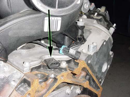
16 FIGURE 6.10 EGR Valve FIGURE 6.11 Knock Sensor Connector FIGURE 6.1 Oxygen Sensor FIGURE 6.13 MAP Sensor FIGURE 6.14 CMP Sensor FIGURE 6.15 CKP Sensor 14


17 FIGURE 6.16 Injectors 1, 3, 5, 7 FIGURE 6.17 Injectors, 4, 6, 8 FIGURE 6.18 TPS Sensor FIGURE 6.19 IAC Sensor FIGURE 6.0 MAF-IAT Sensor FIGURE 6.1 Driver Side Coil Connector 15


18 FIGURE 6. Passenger Side Coil Connector FIGURE 6.3 ECT Sensor Locate the tail section that you earlier separated from the engine group. Begin routing it towards the rear of the vehicle. Be sure to avoid all sharp edges, moving or hot parts, or anything else that may damage the harness. If you ARE using a manual transmission, tape-up the 13-position connectors labeled TRANS, PNP () and store them in the harness. A. BACK-UP (optional)-this circuit is used to power the back-up lamps. This wire will connect directly to the back-up light socket. You will need to splice a wire into this circuit in order to accommodate two back-up lights. B. FROM START SWITCH (optional)-this circuit is used to connect the start switch to the neutral safety switch (omit this circuit if using anything other than an electronic automatic transmission). Connect this wire to a circuit from the ignition switch start position. This wire should only have power in the start position. C. FUEL PUMP (mandatory) - This circuit provides power to the electric fuel pump. Connect this wire to the positive side of the electric fuel pump. This wire only has power for a few seconds when the ignition switch is turned on. It will have constant power while the engine is cranking/ running. D. INPUT SPEED SEN (optional) (not equipped on all models) This connection is only used on the 4L80E/ 4L85E transmissions. This will rarely be used and can be stowed if not needed. E. OUTPUT SPEED SEN (optional) The Vehicle Speed Sensor (VSS) is a pulse counter type input that informs the PCM how fast the vehicle is traveling. The VSS system uses an inductive sensor, mounted in the tail housing of the transmission, and a toothed reluctor wheel on the tail shaft. The teeth of the reluctor wheel alternately interfere with the magnetic field of the sensor creating an induced voltage pulse as the reluctor rotates. 16

19 F. PNP (optional) The Transmission Range Switch (PRND) switch is mounted to the side of the transaxle and is part of the Park Neutral Position (PNP) switch. The PRND switch is used by the PCM to indicate the actual gear selected. The PRND is made up of 4 individual switches. The scan tool indicates ON or OFF for each switch depending on the position of the gear selector lever. The combination of ONs and OFFs will indicate the gear selected. If the combination of ONs and OFFs is invalid, a DTC is set. G. TO STARTER RELAY (optional) - This circuit is used to connect the neutral safety switch to the starter relay terminal #85 (omit this circuit if using anything other than an electronic automatic transmission). Connect this wire to the circuit in terminal #85 of the starter relay. DO NOT CONNECT THIS CIRCUIT DIRECTLY TO THE STARTER SOLENOID. You can substitute Painless part #300 (Hot Shot Relay) if the stock starter relay is not available. H. TRANS (optional) These circuits are used by the PCM to determine vehicle speed, gear position and control shift patterns. WIRE COLOR # OF POSITIONS LABELED CONNECT TO: IN CONNECTOR Blue, Pink/White, Lt.Green, Red, 13 TRANS Transmission Yellow/Black, Black, Tan/Black, Brown, Lt.Blue/White, Red/Black, Yellow, Pink, White Pink, Black/White, Purple/ White, Yellow, 5 PNP Lt.Green Black/ White, Gray, White, Yellow 4 PNP Red/ Black, Blue/ White Lt.Green/ Black, Purple/ White Gray Purple/ White Lt.Green Yellow TABLE 6.3 Tail Section Connections INPUT SPEED SEN VSS SEN FUEL PUMP FROM START SWITCH BACK-UP TO START RELAY Park Neutral Position Sensor Park Neutral Position Sensor Input Speed Sensor Output Speed Sensor Fuel Pump B+ Start Switch Back-up Light Bulbs Starter Relay Activation FIGURE 6.4 VSS Sensor (4L60E) FIGURE 6.5 VSS & Input Speed Sensor, Transmission Connection(4L80E) 17


20 FIGURE 6.6 Transmission Connection FIGURE 6.7 Park Neutral Position Sensor 6.5 Converting the 4L60E Transmission Connector to a 4L80E Connector *Note: Harness numbers 6017and 6018 have been wired for both the 4L60E and the 4L80E. All harnesses have the transmission connector pre terminated to allow use of the 4L60E transmission. In applications where a 4L80E is to be used, follow this procedure to change your transmission connector to ensure all functions of the transmission work properly. See Figure 6.8 for repining the transmission connector 1. With the terminal end of the connector and the arrow on top pointing towards you, carefully remove the white retaining lock located in the center of the connector.. Locate the white wire located in terminal location S. Using a paper clip or small screwdriver, gently lift the locking tab inside the connector and pull the wire from it s location. 3. Now locate the brown wire located in terminal location U. Using the same method, remove the brown wire from it s location 4. Gently insert the brown wire into terminal location S. 5. The white wire has no function with the 4L80E transmission; it needs to be taped up and stowed in the harness in case a 4L60E is ever to be used. Figure 6.8 Transmission Connector Pin Out 18
21 7.0 TROUBLE- SHOOTING INSTRUCTIONS FIGURE 7.1 Fuse Identification 7.1 THE "CHECK ENGINE" LIGHT Normally, the "check engine" light should come on when the ignition is turned on, and then go out a few moments after the engine starts running. If it reappears, or stays on while the engine is running, the computer has detected a problem and a trouble code has been set. NOTE: Most likely the check engine light will come on and stay on when using a computer with the original factory programming. This is why we recommend that the computer be reprogrammed to remove any items that the factory vehicle had that aren t being used in the vehicle you are installing the engine into. 7. RETRIEVING TROUBLE CODES FROM THE COMPUTER Diagnosing problems in modern automobiles can sometimes be very frustrating and confusing, especially when it involves computer controlled systems. The fact is, for the most part automotive electronics have been proven quite reliable, and the greatest number of problems with new cars is the same kinds of problems that older cars without computer controls have. Begin all troubleshooting by checking the basics. Certain basic faults may be undetectable by the Powertrain Control Module (PCM) self-diagnostic system and can actually interfere with self-checking and fault memory operation. Low battery voltage, for example, can cause erroneous faults to set in PCM memory or can cause a system to go "Fail Safe" without setting a fault in memory. Because system faults memory is cleared whenever PCM or battery are disconnected, fault codes should be read prior to any vehicle power interruption or troubleshooting. Before suspecting a computer problem, perform a careful visual inspection. Check under the hood for the same kinds of problems you would look for on a non-computer controlled engine. These include fluid leaks, vacuum leaks, dirty filters, overheating, oil burning, poor connections or loose wires, bad spark plug wires and/or spark plugs, restricted mufflers and exhaust systems, worn mechanical parts, exhaust leaks, and other familiar kinds of problems. Be thorough! You may save a lot of time. 19
22 The PCM is designed to withstand normal current draws associated with vehicle operations. Avoid overloading any circuit. When testing for opens or shorts, do not ground any of the PCM circuits unless instructed. When testing for opens or shorts, do not apply voltage to any of the PCM circuits unless instructed. Only test these circuits with a DMM while the PCM connectors remain connected. PROCEDURE A Tech II or equivalent Scan tool must be used to check or clear Diagnostic Trouble Codes (DTCs) from the PCM memory. When clearing DTCs, follow the instructions supplied by the Scan tool manufacturer. NOTES: Do not clear the DTCs unless directed to do so by the service information provided for each diagnostic procedure. All of the diagnostic data that was saved along with the DTC (freeze frame data and/or malfunction history records) which may be helpful for some diagnostic procedures will be erased from the memory when the DTCs are cleared. Interrupting PCM battery voltage to clear DTCs is NOT recommended and will not turn off the check engine light. Once a DTC has been identified, contact the Painless tech dept. or a GM Service Manual for a procedure to identify why a particular code is being set. Do not assume a code for a component is the result of the component being faulting and its replacement will solve the reason for the code. This could result in unnecessary replacement of functioning components. 7.3 IDLE LEARN PROCEDURE Anytime the Powertrain Control Module (PCM) or the battery is disconnected, the PCM loses power, or the PCM is reprogrammed, the PCMs learned idle position is lost. The engine idle is unstable when the learned idle position is lost. Perform the following procedure in order to return the learned idle to the correct position: AUTOMATIC TRANSMISSION 1. Turn OFF the ignition.. Restore the PCM battery feed. 3. Turn OFF the A/C controls. 4. Set the parking brake and block the drive wheels. 5. Start the engine. 6. Ensure that the engine coolant temperature is more than 80 C (176 F). 7. Shift the transmission into Drive. 8. Allow the engine to idle for 5 minutes. 9. Shift the transmission into Park. 10. Allow the engine to idle for 5 minutes. 11. Turn OFF the engine for 30 seconds. 0
23 7.3. MANUAL TRANSMISSION 1. Turn OFF the ignition.. Restore the PCM battery feed. 3. Turn OFF the A/C controls. 4. Set the parking brake and block the drive wheels. 5. Place the transmission in Neutral. 6. Start the engine. 7. Ensure that the engine coolant temperature is more than 80 C (176 F). 8. Allow the engine to idle for 5 minutes. 9. Turn OFF the engine for 30 seconds. We have attempted to provide you with the most accurate instructions possible, and are always concerned about corrections or improvements that can be made. If you have found any errors or omissions, or if you simply have comments or suggestions concerning these instructions, please write us at the address on the cover and let us know about them. Or, better yet, send us a fax at (817) We sincerely appreciate your business. Painless Performance Products would like to thank the following the manufactures/ suppliers for their contributions to this project: PowerMaster Fuel Injection Specialties Phoenix Transmissions Forrest Pontiac Chandlers Auto Supply TLC 1
24 Painless Performance Limited Warranty and Return Policy Chassis harnesses, fuel injection harnesses, and Striker ColdShot units are covered under a lifetime warranty. All other products manufactured and/or sold by Painless Performance are warranted to the original purchaser to be free from defects in material and workmanship under normal use. Painless Performance will repair or replace defective products without charge during the first 1 months from the purchase date. No products will be considered for warranty without a copy of the purchase receipt showing the sellers name, address and date of purchase. You must return the product to the dealer you purchased it from to initiate warranty procedures.
Manual P/N Copyright Third Edition June 21, 2005
 P/N 60212, 60213, 60214 & 60215 1996-99 GM VORTEC WIRE HARNESS INSTALLATION INSTRUCTIONS Manual P/N 90524 Copyright 2003 Third Edition June 21, 2005 PAINLESS PERFORMANCE PRODUCTS 2501 Ludelle Street, Fort
P/N & GM LS1 FUEL INJECTION WIRE P/N & GM LS1 FUEL INJECTION WIRE HARNESS INSTALLATION INSTRUCTIONS
 P/N 60506 & 60507 1997-98 GM LS1 FUEL INJECTION WIRE HARNESS INSTALLATION INSTRUCTIONS P/N 60508 & 60509 1999-0 GM LS1 FUEL INJECTION WIRE HARNESS INSTALLATION INSTRUCTIONS Manual P/N 9050 Seventh Edition
P/N & GM LS1 w/mechanical (cable) THROTTLE BODY FUEL INJECTION WIRE HARNESS INSTALLATION INSTRUCTIONS
 THROTTLE BODY FUEL INJECTION WIRE HARNESS INSTALLATION INSTRUCTIONS") P/N 60508 & 60509 1997-0 GM LS1 w/mechanical (cable) THROTTLE BODY FUEL INJECTION WIRE HARNESS INSTALLATION INSTRUCTIONS Manual P/N 9050 Painless Performance Products, LLC 501 Ludelle Street Fort Worth,
P/N 60508 & 60509 1997-0 GM LS1 w/mechanical (cable) THROTTLE BODY FUEL INJECTION WIRE HARNESS INSTALLATION INSTRUCTIONS Manual P/N 9050 Painless Performance Products, LLC 501 Ludelle Street Fort Worth,
P/N GM VORTEC THROTTLE BY WIRE FUEL INJECTION 4.8L, 5.3L & 6.0L WIRE HARNESS INSTALLATION INSTRUCTIONS
 P/N 60221 2003-2006 GM VORTEC THROTTLE BY WIRE FUEL INJECTION 4.8L, 5.3L & 6.0L WIRE HARNESS INSTALLATION INSTRUCTIONS Manual P/N 90570 FIRST EDITION September 2009 Copyright SEPTEMBER 2009 PAINLESS PERFORMANCE
P/N & /1995 GM LT1 FUEL INJECTION WIRE HARNESS INSTALLATION INSTRUCTIONS
 P/N 60502 & 60505 1994/1995 GM LT1 FUEL INJECTION WIRE HARNESS INSTALLATION INSTRUCTIONS Manual P/N 90517 Copyright May 2002 PAINLESS PERFORMANCE PRODUCTS 2501 Ludelle Street - Fort Worth, Texas 76105-1036
P/N & GM LS1 FUEL INJECTION WIRE HARNESS INSTALLATION INSTRUCTIONS
 P/N 605 & 6053 00-04 GM LS1 FUEL INJECTION WIRE HARNESS INSTALLATION INSTRUCTIONS Manual P/N 90544 nd Edition July 014 PAINLESS PERFORMANCE PRODUCTS 501 Ludelle Street - Fort Worth, Texas 76105-1036 -
Vortec Drive by Cable Electronic Fuel Injection Wiring Harness (P/N HAR-1018) HAR-1018
 HAR-1018") 1998 2002 Vortec Drive by Cable Electronic Fuel Injection Wiring Harness (P/N HAR-1018) HAR-1018 PERFORMANCE SYSTEMS INTEGRATION 170 Oberlin Ave N Suite 13 Lakewood NJ 08701-4548 Ph: 732-444-3277 Email:
1998 2002 Vortec Drive by Cable Electronic Fuel Injection Wiring Harness (P/N HAR-1018) HAR-1018 PERFORMANCE SYSTEMS INTEGRATION 170 Oberlin Ave N Suite 13 Lakewood NJ 08701-4548 Ph: 732-444-3277 Email:
Wire Harness Installation Instructions
 Wire Harness Installation Instructions For Installing: Part #50001 Race Car Kit/8 Circuit Part #50201 8 Switch Dash Mounted Panel Part #50202 8 Switch Roll Bar Mounted Panel Manual #90502 Painless Performance
'05- 'Current LS2/LS3 Drive by Cable Electronic Fuel Injection Wiring Harness HAR-1058
 '05- 'Current LS2/LS3 Drive by Cable Electronic Fuel Injection Wiring Harness HAR-1058 PERFORMANCE SYSTEMS INTEGRATION 170 Oberlin Ave N Suite 13 Lakewood NJ 08701-4548 Ph: 732-444-3277 Email: INFO@PSIConversion.com
GM VORTEC Drive by Wire Electronic Fuel Injection Wiring Harness HAR-1014
 GM VORTEC Drive by Wire Electronic Fuel Injection Wiring Harness HAR-1014 PERFORMANCE SYSTEMS INTEGRATION 170 Oberlin Ave N Suite 13 Lakewood NJ 08701-4548 Ph: 732-444-3277 Email: INFO@PSIConversion.com
SUM EFI Wiring Harness for GM LT-1/LT-4 Engine INSTALLATION INSTRUCTIONS
 SUM-890121 EFI Wiring Harness for GM LT-1/LT-4 Engine INSTALLATION INSTRUCTIONS INTRODUCTION This harness is designed for GM 1992-97 LT1/LT4 fuel injected engines. Even with minimal electrical experience,
P/N & GM LS2 FUEL INJECTION WIRE HARNESS INSTALLATION INSTRUCTIONS. Manual P/N 90543
 P/N 6050 & 6051 005-06 GM LS FUEL INJECTION WIRE HARNESS INSTALLATION INSTRUCTIONS Manual P/N 90543 1 Painless Performance Products, LLC 501 Ludelle Street Fort Worth, TX 76105-1036 800-43-9696 phone 817-44-404
PERFORMANCE SYSTEMS INTEGRATION
 2006 Current GEN IV LSX/Vortec 4.8, 5.3, 6.0, 6.2, 7.0 Drive by Wire (58X) Electronic Fuel Injection Wiring Harness w/ Manual or Non- Electronic Automatic Transmission HAR-10 (See Below) (P/N HAR- 1035,
SUM EFI Wiring Harness for GM LS1 Engine INSTALLATION INSTRUCTIONS
 SUM-890122 EFI Wiring Harness for GM LS1 Engine INSTALLATION INSTRUCTIONS 1 INTRODUCTION This harness is designed for GM 1997-2002 LS1 fuel injected engines utilizing a mechanical throttle body and throttle
VORTEC Drive by Wire Electronic Fuel Injection Wiring Harness HAR-1085
 2001 2002 VORTEC Drive by Wire Electronic Fuel Injection Wiring Harness HAR-1085 PERFORMANCE SYSTEMS INTEGRATION 170 Oberlin Ave N Suite 13 Lakewood NJ 08701-4548 Ph: 732-444-3277 Email: INFO@PSIConversion.com
TELORVEK II RJ-32 Big Block RamJet Fuel Injection System
 Page #1 TELORVEK II RJ-32 Big Block RamJet Fuel Injection System This wiring system is compatible with the GM Performance part big block Ramjet 502 engine. The harness is designed to dress up the appearance
TELORVEK EFI 5.0 Coyote Sequential Fuel Injection System Part # CY-11
 Page #1 TELORVEK EFI 5.0 Coyote Sequential Fuel Injection System Part # CY-11 WIRING INSTRUCTIONS Thank you for purchasing the absolute finest of wiring kits for the Ford Motor Co. Coyote modular engine.
Powertrain DTC Summaries EOBD
 Powertrain DTC Summaries Quick Reference Diagnostic Guide Jaguar X-TYPE 2.0 L 2002.25 Model Year Refer to page 2 for important information regarding the use of Powertrain DTC Summaries. Jaguar X-TYPE 2.0
2002 ENGINE PERFORMANCE. Self-Diagnostics - RAV4. Before performing testing procedures, check for any related Technical Service Bulletins (TSBs).
.") 2002 ENGINE PERFORMANCE Self-Diagnostics - RAV4 INTRODUCTION NOTE: Before performing testing procedures, check for any related Technical Service Bulletins (TSBs). To properly diagnosis and repair this
2002 ENGINE PERFORMANCE Self-Diagnostics - RAV4 INTRODUCTION NOTE: Before performing testing procedures, check for any related Technical Service Bulletins (TSBs). To properly diagnosis and repair this
Fuel Metering System Component Description
 1999 Chevrolet/Geo Tahoe - 4WD Fuel Metering System Component Description Purpose The function of the fuel metering system is to deliver the correct amount of fuel to the engine under all operating conditions.
TELORVEK III WIRING INSTRUCTIONS FOR NS-93A 4.6 NORTHSTAR Fuel Injection System
 Page #1 TELORVEK III WIRING INSTRUCTIONS FOR NS-93A 4.6 NORTHSTAR Fuel Injection System Thank you for purchasing the absolute finest of wiring kits for the General Motors fuel injection. We have taken
TELORVEK TPI WIRING INSTRUCTIONS FOR TH-90 (95 CK TRUCK) 4.3,5.0,5.7,7.4 TBI Fuel Injection System W/4L60-E or 4L80-E Transmission
 4.3,5.0,5.7,7.4 TBI Fuel Injection System W/4L60-E or 4L80-E Transmission") Page #1 TELORVEK TPI WIRING INSTRUCTIONS FOR TH-90 (95 CK TRUCK) 4.3,5.0,5.7,7.4 TBI Fuel Injection System W/4L60-E or 4L80-E Transmission Thank you for purchasing the absolute finest of wiring kits for
Page #1 TELORVEK TPI WIRING INSTRUCTIONS FOR TH-90 (95 CK TRUCK) 4.3,5.0,5.7,7.4 TBI Fuel Injection System W/4L60-E or 4L80-E Transmission Thank you for purchasing the absolute finest of wiring kits for
TELORVEK III. WIRING INSTRUCTIONS FOR LT-40 LT-1 Fuel Injection System
 TELORVEK III WIRING INSTRUCTIONS FOR LT-40 LT-1 Fuel Injection System Page #1 Thank you for purchasing the absolute finest of wiring kits for the General Motors fuel injection. We have taken considerable
Powertrain DTC Summaries EOBD
 Powertrain DTC Summaries Quick Reference Diagnostic Guide Jaguar S-TYPE V6, V8 N/A and V8 SC 2002.5 Model Year Refer to pages 2 9 for important information regarding the use of Powertrain DTC Summaries.
INSTALLATION INSTRUCTIONS
 INSTALLATION INSTRUCTIONS 2009 CORVETTE LS - 9 INSTALLATION INSTRUCTIONS FOR LS 9 The following instructions are intended as an aid to assist in harness installation. More in depth information can be obtained
Powertrain DTC Summaries OBD II
 Powertrain DTC Summaries Quick Reference Diagnostic Guide Jaguar X-TYPE 2.5L and 3.0L 2002 Model Year Revised January, 2002: P0706, P0731, P0732, P0733, P0734, P0735, P0740, P1780 POSSIBLE CAUSES Revised
Wire Harness Installation Instructions
 Wire Harness Installation Instructions For Installing: Part #60101 - GM 86-93 TBI Standard Harness & Part #60201 GM 86-93 TBI Extended Length Harness Manual # 90503 Painless Performance Products, LLC 2501
LSx Harness Installation. lsxeverything.com #BecauseYouShould
 LSx Harness Installation lsxeverything.com #BecauseYouShould Table of Contents Slide 1 Introduction Page Slide 2 Table of Contents Slide 3 Starting Instructions Slide 4 Power Connections Slide 5 Ground
E - THEORY/OPERATION - TURBO
 E - THEORY/OPERATION - TURBO 1995 Volvo 850 1995 ENGINE PERFORMANCE Volvo - Theory & Operation 850 - Turbo INTRODUCTION This article covers basic description and operation of engine performance-related
Motronic September 1998
 The Motronic 1.8 engine management system was introduced with the 1992 Volvo 960. The primary difference between this Motronic system and the previous generation of Volvo LH-Jetronic engine management
1998 ENGINE PERFORMANCE. General Motors Corp. - Basic Diagnostic Procedures - 5.7L
 INTRODUCTION 1998 ENGINE PERFORMANCE General Motors Corp. - Basic Diagnostic Procedures - 5.7L The following diagnostic steps will help prevent overlooking a simple problem. This is also where to begin
G - TESTS W/CODES - 2.2L
 G - TESTS W/CODES - 2.2L 1994 Toyota Celica 1994 ENGINE PERFORMANCE Toyota 2.2L Self-Diagnostics Celica INTRODUCTION If no faults were found while performing F - BASIC TESTING, proceed with self-diagnostics.
Perfect Performance Products, LLC Painless Performance Products Division 2501 Ludelle St. Fort Worth, Texas (800)
") Wire Harness Installation Instructions For Installing: Part # 65104 Into 1985-1992 (5.0 & 5.7L) TPI Engines Manual # 90536 Perfect Performance Products, LLC Painless Performance Products Division 2501
Wire Harness Installation Instructions For Installing: Part # 65104 Into 1985-1992 (5.0 & 5.7L) TPI Engines Manual # 90536 Perfect Performance Products, LLC Painless Performance Products Division 2501
TELORVEK EFI. 4S. S e. n s tem. a l Fue l I n j e cti
 Page #1 4.63 V &5 TELORVEK EFI. 4S /C S e q uen i t a l Fue l I n j e cti o n Sy s tem MG-05 / MG-05A WIRING INSTRUCTIONS Thank you for purchasing the absolute finest of wiring kits for the Ford Motor
Diagnostic Trouble Code (DTC) memory, checking and erasing
 memory, checking and erasing") Page 1 of 49 01-12 Diagnostic Trouble Code (DTC) memory, checking and erasing Check DTC Memory (function 02) - Connect VAS5051 tester Page 01-7 and select vehicle system "01 - Engine electronics". Engine
Page 1 of 49 01-12 Diagnostic Trouble Code (DTC) memory, checking and erasing Check DTC Memory (function 02) - Connect VAS5051 tester Page 01-7 and select vehicle system "01 - Engine electronics". Engine
Wire Harness Installation Instructions
 Wire Harness Installation Instructions For Installing: Part #60102 - GM 86-89 TPI Mass Air Flow (MAF) Standard Harness Part #60103 - GM 90-92 TPI w/speed Density (MAP) Standard Harness Part #60202 - GM
TELORVEK TPI WIRING INSTRUCTIONS FOR LS Camaro/Firebird LS-1 Fuel Injection System
 Page #1 TELORVEK TPI WIRING INSTRUCTIONS FOR LS-85 98 Camaro/Firebird LS-1 Fuel Injection System Thank you for purchasing the absolute finest of wiring kits for the General Motors fuel injection. We have
Diagnostic Trouble Code (DTC) List - Vehicle
 List - Vehicle") Document ID# 850406 2002 Pontiac Firebird Diagnostic Trouble Code (DTC) List - Vehicle DTC DTC 021 and/or 031 DTC 022 and/or 032 DTC 023 or 033 DTC 24/34 DTC 025 and/or 035 DTC 041 DTC 042 DTC 043 DTC
Document ID# 850406 2002 Pontiac Firebird Diagnostic Trouble Code (DTC) List - Vehicle DTC DTC 021 and/or 031 DTC 022 and/or 032 DTC 023 or 033 DTC 24/34 DTC 025 and/or 035 DTC 041 DTC 042 DTC 043 DTC
Powertrain DTC Summaries EOBD
 Powertrain DTC Summaries Quick Reference Diagnostic Guide Jaguar X-TYPE 2.5L and 3.0L 2001.5 Model Year Revised January, 2002: P0706, P0731, P0732, P0733, P0734, P0735, P0740, P1780 POSSIBLE CAUSES Revised
TELORVEK TPI WIRING INSTRUCTIONS FOR TH-100 (96-99 Vortech) 4.3,5.0,5.7,7.4 Fuel Injection System W/4L60-E or 4L80-E Transmission
 4.3,5.0,5.7,7.4 Fuel Injection System W/4L60-E or 4L80-E Transmission") Page #1 TELORVEK TPI WIRING INSTRUCTIONS FOR TH-100 (96-99 Vortech) 4.3,5.0,5.7,7.4 Fuel Injection System W/4L60-E or 4L80-E Transmission Thank you for purchasing the absolute finest of wiring kits for
Page #1 TELORVEK TPI WIRING INSTRUCTIONS FOR TH-100 (96-99 Vortech) 4.3,5.0,5.7,7.4 Fuel Injection System W/4L60-E or 4L80-E Transmission Thank you for purchasing the absolute finest of wiring kits for
Trail Rocker Installation Instructions
 Trail Rocker Installation Instructions Manual #90580 For Installing Painless Part Numbers: 57000 and 57001 Painless Performance Products recommends you, the installer, read this installation manual from
Trail Rocker Installation Instructions
 Trail Rocker Installation Instructions Manual #90581 For Installing Painless Part Numbers: 57002 Painless Performance Products recommends you, the installer, read this installation manual from front to
TELORVEK EFI 4.6 Sequential Fuel Injection System MK-97A
 Page #1 TELORVEK EFI 4.6 Sequential Fuel Injection System MK-97A WIRING INSTRUCTIONS Thank you for purchasing the absolute finest of wiring kits for the Ford Motor Co. 4.6. This harness works with 1999
Part Number: TDZ-75SD / BRONCO-75SD
 Ford 5.0 EFI Harness Installation Manual For Classic Fords & Mustangs and Early Broncos Part Number: TDZ-75SD / BRONCO-75SD Ron Francis Wiring & The Detail Zone 200 Keystone Rd. Chester, PA 19013 800-292-1940
LB-47 TELORVEK TPI. WIRING INSTRUCTIONS FOR Olds / Aurora 4.0 V-8 ENGINE
 Page #1 LB-47 TELORVEK TPI WIRING INSTRUCTIONS FOR Olds / Aurora 4.0 V-8 ENGINE Thank you for purchasing the absolute finest of wiring kits for the General Motors fuel injection. We have taken considerable
4.0L CEC SYSTEM Jeep Cherokee DESCRIPTION OPERATION FUEL CONTROL DATA SENSORS & SWITCHES
 4.0L CEC SYSTEM 1988 Jeep Cherokee 1988 COMPUTERIZED ENGINE Controls ENGINE CONTROL SYSTEM JEEP 4.0L MPFI 6-CYLINDER Cherokee, Comanche & Wagoneer DESCRIPTION The 4.0L engine control system controls engine
Zoom and Print Options
 Vehicle» Engine, Cooling and Exhaust» Engine» Service and Repair» Removal and Replacement» Engine Replacement Engine Replacement ^ Tools Required - J 38185 Hose Clamp Pliers Removal Procedure 1. Remove
HOWELL INSTALLATION MANUAL. Throttle Body Fuel Injection Harness
 HOWELL ENGINE DEVELOPMENTS, INC. FUEL INJECTION APPLICATIONS INSTALLATION MANUAL Throttle Body Fuel Injection Harness Howell Engine Developments, Inc. 6201 Industrial Way Marine City, MI 48039 Phone: 810-765-5100
Wire Harness Installation Instructions
 Wire Harness Installation Instructions For Installing: Part #60102 - GM 86-89 TPI Mass Air Flow (MAF) Standard Harness Part #60103 - GM 90-92 TPI w/speed Density (MAP) Standard Harness Part #60202 - GM
DTC P1415 Secondary Air Injection (AIR) System Bank 1
 System Bank 1") Page 1 of 5 2000 GMC Truck GMC K Sierra - 4WD Sierra, Silverado, Suburban, Tahoe, Yukon (VIN C/K) Service Manual Document ID: 546887 DTC P1415 Secondary Air Injection (AIR) System Bank 1 Circuit Description
Page 1 of 5 2000 GMC Truck GMC K Sierra - 4WD Sierra, Silverado, Suburban, Tahoe, Yukon (VIN C/K) Service Manual Document ID: 546887 DTC P1415 Secondary Air Injection (AIR) System Bank 1 Circuit Description
Diagnostic Trouble Code (DTC) table
 table") Page 1 of 40 01-19 Diagnostic Trouble Code (DTC) table Note: When malfunctions occur in monitored sensors or components, Diagnostic Trouble Codes (DTCs) are stored in DTC memory with a description of the
Page 1 of 40 01-19 Diagnostic Trouble Code (DTC) table Note: When malfunctions occur in monitored sensors or components, Diagnostic Trouble Codes (DTCs) are stored in DTC memory with a description of the
ENGINE 01 02A 1. Toc of SCT ON-BOARD DIAGNOSTIC [ENGINE. Toc of SCT 01 02A ON-BOARD DIAGNOSTIC [ENGINE CONTROL SYSTEM (ZM)] 01 02A
![ENGINE 01 02A 1. Toc of SCT ON-BOARD DIAGNOSTIC [ENGINE. Toc of SCT 01 02A ON-BOARD DIAGNOSTIC [ENGINE CONTROL SYSTEM (ZM)] 01 02A](/thumbs/90/103285807.jpg "ENGINE 01 02A 1. Toc of SCT ON-BOARD DIAGNOSTIC [ENGINE. Toc of SCT 01 02A ON-BOARD DIAGNOSTIC [ENGINE CONTROL SYSTEM (ZM)] 01 02A") ENGINE 01 SECTION Toc of SCT ON-BOARD DIAGNOSTIC [ENGINE CONTROL SYSTEM (ZM)]...01-02A ON-BOARD DIAGNOSTIC [ENGINE CONTROL SYSTEM (FS)]...01-02B ON-BOARD DIAGNOSTIC [CRUISE CONTROL SYSTEM].......01-02C
ENGINE 01 SECTION Toc of SCT ON-BOARD DIAGNOSTIC [ENGINE CONTROL SYSTEM (ZM)]...01-02A ON-BOARD DIAGNOSTIC [ENGINE CONTROL SYSTEM (FS)]...01-02B ON-BOARD DIAGNOSTIC [CRUISE CONTROL SYSTEM].......01-02C
90558 Installation Manual For # Cummins 5.9L Common Rail Diesel
 2501 Ludelle Street Fort Worth, Texas 76105 817-244-6212 Phone 817-244-4024 Fax 888-350-6588 Sales 800-423-9696 Tech E-mail: painless@painlessperformance.com Web: www.painlessperformance.com 90558 Installation
PIMP Ford 5.0 Harness Installation Manual. Part Number: PM-75
 PIMP Ford 5.0 Harness Installation Manual Part Number: PM-75 Ron Francis Wiring 200 Keystone Rd Suite 1 Chester, PA 19013 800-292-1940 www.ronfrancis.com Pre-Installation Notes: This system is designed
For Troubleshooting of DTC related components, see chart on page INTAKE AIR BYPASS (IAB) HIGH CONTROL SOLENOID
 HIGH CONTROL SOLENOID") Index For Troubleshooting of DTC related components, see chart on page 11-53. '96-99 models: EXHAUST GAS RECIRCULATION (EGR) and LIFT MANIFOLD ABSOLUTE PRESSURE (MAP) INTAKE AIR BYPASS (IAB) HIGH page
Index For Troubleshooting of DTC related components, see chart on page 11-53. '96-99 models: EXHAUST GAS RECIRCULATION (EGR) and LIFT MANIFOLD ABSOLUTE PRESSURE (MAP) INTAKE AIR BYPASS (IAB) HIGH page
Service Bulletin. DTC Detection Item Associated Monitor
 Service Bulletin 03-010 Applies To: All OBD II equipped models except SLX March 29, 2003 OBD II DTCs and Their Associated Monitors This is a list of all DTCs for all OBD II models. No one model has all
Motronic injection system,
 Page 1 of 78 24-1 Motronic injection system, servicing Safety precautions If special testing equipment is required during road test, note the following: WARNING! Scan tools and testing devices must always
01 02B ON-BOARD DIAGNOSTIC [ENGINE CONTROL SYSTEM (FS)]
![01 02B ON-BOARD DIAGNOSTIC [ENGINE CONTROL SYSTEM (FS)]](/thumbs/80/80600627.jpg "01 02B ON-BOARD DIAGNOSTIC [ENGINE CONTROL SYSTEM (FS)]") ON-BOARD DIAGNOSTIC [ENGINE CONTROL SYSTEM (FS)] CONTROL SYSTEM WIRING DIAGRAM [FS]............................ 2 CONTROL SYSTEM DEVICE AND CONTROL RELATIONSHIP CHART [FS]........ 4 Engine Control System............
ON-BOARD DIAGNOSTIC [ENGINE CONTROL SYSTEM (FS)] CONTROL SYSTEM WIRING DIAGRAM [FS]............................ 2 CONTROL SYSTEM DEVICE AND CONTROL RELATIONSHIP CHART [FS]........ 4 Engine Control System............
BASIC DIAGNOSTIC PROCEDURES
 BASIC DIAGNOSTIC PROCEDURES 2001 Chevrolet Camaro 2001 ENGINE PERFORMANCE Basic Diagnostic Procedures - Cars Except Metro & Prizm MODEL IDENTIFICATION MODEL IDENTIFICATION Body Code (1) Model C... Park
1. Connect the Honda PGM Tester or an OBD II scan tool to the 16P Data Link Connector (DLC) located behind the right side of the center console.
 located behind the right side of the center console.") Troubleshooting Procedures I. How To Begin Troubleshooting When the Malfunction indicator Lamp (MIL) has been reported on, or there is a driveability problem, use the appropriate procedure below to diagnose
Troubleshooting Procedures I. How To Begin Troubleshooting When the Malfunction indicator Lamp (MIL) has been reported on, or there is a driveability problem, use the appropriate procedure below to diagnose
HOWELL INSTALLATION MANUAL. Tuned Port Or LT-1 Fuel Injection Harness ( )
") HOWELL ENGINE DEVELOPMENTS, INC. FUEL INJECTION APPLICATIONS INSTALLATION MANUAL Tuned Port Or LT-1 Fuel Injection Harness (1985-1992) Howell Engine Developments, Inc. 6201 Industrial Way Marine City,
HOWELL ENGINE DEVELOPMENTS, INC. FUEL INJECTION APPLICATIONS INSTALLATION MANUAL Tuned Port Or LT-1 Fuel Injection Harness (1985-1992) Howell Engine Developments, Inc. 6201 Industrial Way Marine City,
DO NOT adjust by-pass valve full-close screw. Adjustment is preset at factory.
 I - SYSTEM/COMPONENT TESTS Article Text 1993 Honda Prelude For Cadi Centre Nsk CA 95051 Copyright 1998 Mitchell Repair Information Company, LLC Sunday, July 08, 2001 11:31AM ARTICLE BEGINNING 1993 ENGINE
ARTICLE BEGINNING INTRODUCTION SELF-DIAGNOSTIC SYSTEM RETRIEVING DTCS ENGINE PERFORMANCE Volkswagen Self-Diagnostics - Gasoline
 Article Text ARTICLE BEGINNING 1996 ENGINE PERFORMANCE Volkswagen Self-Diagnostics - Gasoline Cabrio, Golf III, GTI, Jetta III, Passat INTRODUCTION If no faults were found while performing preliminary
DTC Summaries. NipponDenso V12 Engine Management
 DTC Summaries NipponDenso V12 Engine Management OBD II MONITORING CONDITIONS: When testing for DTC reoccurrence, it can be determined if the Service Drive Cycle was of sufficient length by performing a
FUEL INJECTION SYSTEM - MULTI-POINT
 FUEL INJECTION SYSTEM - MULTI-POINT 1988 Jeep Cherokee 1988 Electronic Fuel Injection JEEP MULTI-POINT 4.0L Cherokee, Comanche, Wagoneer DESCRIPTION The Multi-Point Electronic Fuel Injection (EFI) system
PERFECT HI-VELOCITY 62MM THROTTLE BODY
 PERFECT HI-VELOCITY 62MM THROTTLE BODY Installation Instructions Part # 65300 1991-1998 Jeep 4.0L Engines OR All Jeep 4.0L Engines in Cherokee, Grand Cherokee and Wrangler 1991-2005 w/4 wire IAC ONLY.
Track Rocker Installation Instructions
 Track Rocker Installation Instructions For Installing Painless Part Numbers: 58103: 8-Switch Customizable Track Rocker Switch Panel w/ Flanged Mount 58106: 6-Switch Customizable Track Rocker Switch Panel
Perfect Performance Products, LLC Painless Performance Products Division 2501 Ludelle St. Fort Worth, Texas (800)
") Camshaft Installation Instructions For Installing: Part # 65206 1997-2004 (5.7L) LS-1 Engines Perfect Performance Products, LLC Painless Performance Products Division 2501 Ludelle St. Fort Worth, Texas
Camshaft Installation Instructions For Installing: Part # 65206 1997-2004 (5.7L) LS-1 Engines Perfect Performance Products, LLC Painless Performance Products Division 2501 Ludelle St. Fort Worth, Texas
Trail Rocker Installation
 Trail Rocker Installation Instructions Customizable Trail Rocker Control System For Installing Painless Part Number: 57100 Manual #90616 Painless Performance Products recommends you, the installer, read
2.8 Liter VR6 2V Fuel Injection & Ignition, Engine Code(s): AAA m.y
: AAA m.y") 2.8 Liter VR6 2V Fuel Injection & Ignition, Engine Code(s): AAA m.y. 1996-1997 01 - On Board Diagnostic (OBD) On Board Diagnostic (OBD II) Malfunction Indicator Lamp (MIL) On Board Diagnostic (OBD II),
2.8 Liter VR6 2V Fuel Injection & Ignition, Engine Code(s): AAA m.y. 1996-1997 01 - On Board Diagnostic (OBD) On Board Diagnostic (OBD II) Malfunction Indicator Lamp (MIL) On Board Diagnostic (OBD II),
TELORVEK EFI 4.6 Sequential Fuel Injection System (MG-91A)
") Page #1 TELORVEK EFI 4.6 Sequential Fuel Injection System (MG-91A) WIRING INSTRUCTIONS Thank you for purchasing the absolute finest of wiring kits for the 1996-98 Ford Motor Co. 4.6 / COBRA fuel injection
Page #1 TELORVEK EFI 4.6 Sequential Fuel Injection System (MG-91A) WIRING INSTRUCTIONS Thank you for purchasing the absolute finest of wiring kits for the 1996-98 Ford Motor Co. 4.6 / COBRA fuel injection
7. Remove the starter motor. Refer to Starter Motor Replacement (2.2L) or Starter Motor Replacement (4.3L).
 or Starter Motor Replacement (4.3L).") 1 of 9 1/5/2013 6:40 PM Removal Procedure 1. Disconnect the battery negative cable. Refer to Battery Replacement. 2. Remove the hood. Refer to Hood Replacement. 3. If the vehicle is equipped with a manual
1 of 9 1/5/2013 6:40 PM Removal Procedure 1. Disconnect the battery negative cable. Refer to Battery Replacement. 2. Remove the hood. Refer to Hood Replacement. 3. If the vehicle is equipped with a manual
TELORVEK IV Ford Turbo 2.3 Fuel Injection System (MG-60)
") Page #1 TELORVEK IV Ford Turbo 2.3 Fuel Injection System (MG-60) WIRING INSTRUCTIONS Thank you for purchasing the absolute finest of wiring kits for the Ford Motor Co. fuel injection. We have taken considerable
Page #1 TELORVEK IV Ford Turbo 2.3 Fuel Injection System (MG-60) WIRING INSTRUCTIONS Thank you for purchasing the absolute finest of wiring kits for the Ford Motor Co. fuel injection. We have taken considerable
Wire Harness Installation Instructions
 Wire Harness Installation Instructions For Installing: #10127 Customizable Mopar Chassis Harness 21 Circuit Manual #90542 Painless Performance Products, LLC 2501 Ludelle Street Fort Worth, TX 76105-1036
EMISSION CONTROL (AUX. EMISSION CONTROL DEVICES) H6DO
 H6DO") EMISSION CONTROL (AUX. EMISSION CONTROL DEVICES) H6DO SYSTEM OVERVIEW 1. System Overview There are three emission control systems, which are as follows: Crankcase emission control system Exhaust emission
EMISSION CONTROL (AUX. EMISSION CONTROL DEVICES) H6DO SYSTEM OVERVIEW 1. System Overview There are three emission control systems, which are as follows: Crankcase emission control system Exhaust emission
Auto Diagnosis Test #7 Review
 Auto Diagnosis Test #7 Review Your own hand written notes may be used for the 1 st 10 minutes of the test Based on Chapters 25, 26, 32, 33, 34 and Lab Demonstrations Auto Diagnosis Test #7 Review Your
DTC P0171, P0172, P0174, or P0175
 Page 1 of 6 2009 Pontiac G8 G8 Service Manual Document ID: 2076050 DTC P0171, P0172, P0174, or P0175 Diagnostic Instructions Perform the Diagnostic System Check - Vehicle prior to using this diagnostic
Lower Intake Manifold Replacement
 Lower Intake Manifold Replacement Removal Procedure 1. Turn OFF all the lamps and the accessories. 2. Ensure the ignition switch is in the OFF position. 3. Disconnect the negative battery cable from the
Installation Tips for your Crimestopper/ProStart Remote Start system (for GM vehicles) v1.01 updated 2/27/2012
 v1.01 updated 2/27/2012") Installation Tips for your Crimestopper/ProStart Remote Start system (for GM vehicles) v1.01 updated 2/27/2012 Thank you for purchasing your remote start from MyPushcart.com - an industry leader in providing
Installation Tips for your Crimestopper/ProStart Remote Start system (for GM vehicles) v1.01 updated 2/27/2012 Thank you for purchasing your remote start from MyPushcart.com - an industry leader in providing
TELORVEK EFI. 4.6 Sequential Fuel Injection System (FT-95) WIRING INSTRUCTIONS
 WIRING INSTRUCTIONS") Page #1 TELORVEK EFI 4.6 Sequential Fuel Injection System (FT-95) WIRING INSTRUCTIONS Thank you for purchasing the absolute finest of wiring kits for the Ford Motor Co. 4.6 94-95 Thunderbird, Cougar fuel
Page #1 TELORVEK EFI 4.6 Sequential Fuel Injection System (FT-95) WIRING INSTRUCTIONS Thank you for purchasing the absolute finest of wiring kits for the Ford Motor Co. 4.6 94-95 Thunderbird, Cougar fuel
Perfect Performance Products, LLC Painless Performance Products Division 2501 Ludelle St. Fort Worth, Texas (800)
") PERFECT HI-VELOCITY 68MM THROTTLE BODY Installation Instructions Part # 65301 1991-1998 Jeep 4.0L Engines w/perfect Engine Management System P/N 65140, 65141 OR All Jeep 4.0L Engines in Cherokee, Grand
PERFECT HI-VELOCITY 68MM THROTTLE BODY Installation Instructions Part # 65301 1991-1998 Jeep 4.0L Engines w/perfect Engine Management System P/N 65140, 65141 OR All Jeep 4.0L Engines in Cherokee, Grand
Engine management/transmission
 MAZDA Model: 323 (BG) 323 Estate 1,6/4x4 (BW) 323 (BA/BJ) 626/MX-6 626/Estate Xedos 6/9 MX-3/MX-5 Year: 1989-00 Engina code: BP, BP-DOHC, B3, B3E, B6, B6-SOHC, B6-DOHC, B6E,FP, FS, KF, KJ, KL K8, RF, RF-CX,
WEBER CARBURETOR TROUBLESHOOTING GUIDE
 This guide is to help pinpoint problems by diagnosing engine symptoms associated with specific vehicle operating conditions. The chart will guide you step by step to help correct these problems. For successful
H - TESTS W/O CODES INTRODUCTION SYMPTOMS
 H - TESTS W/O CODES 1995 Volvo 850 1995 ENGINE PERFORMANCE Volvo - Trouble Shooting - No Codes 850 INTRODUCTION Before diagnosing symptoms or intermittent faults, perform steps in the F - BASIC TESTING
Generation III Stand Alone Engine Harness
 78 Rattler Curry Road, Columbia, KY 42728 Phone 1-888-467-4491 sales@bp-automotive.com www.bp-automotive.com Generation III Stand Alone Engine Harness Installation Guide At BP Automotive we take pride
Diagnostic Trouble Codes (continued) GM Specific Codes
 GM Specific Codes") 85 GM Specific Codes P11XX Fuel and Air Metering P1106 MAP Sensor Circuit Intermittent High Voltage P1107 MAP Sensor Circuit Intermittent Low Voltage P1108 BARO to MAP Signal Comparison Too High P1111
85 GM Specific Codes P11XX Fuel and Air Metering P1106 MAP Sensor Circuit Intermittent High Voltage P1107 MAP Sensor Circuit Intermittent Low Voltage P1108 BARO to MAP Signal Comparison Too High P1111
Installation Tips Crimestopper/ProStart Remote Start system + PLJX + DLRM + SPDT (for GM vehicles) T0760 v1.1 updated 2/5/14
 T0760 v1.1 updated 2/5/14") Installation Tips Crimestopper/ProStart Remote Start system + PLJX + DLRM + SPDT (for GM vehicles) T0760 v1.1 updated 2/5/14 Thank you for purchasing your remote start from MyPushcart.com - an industry
Installation Tips Crimestopper/ProStart Remote Start system + PLJX + DLRM + SPDT (for GM vehicles) T0760 v1.1 updated 2/5/14 Thank you for purchasing your remote start from MyPushcart.com - an industry
This is the layout of a typical harness form a TPI Camaro.
 TPI wiring harness, typical 1986-89: This is the layout of a typical harness form a 1986-88 TPI Camaro. (A) bulkhead conn. through firewall. (B) ecm conn. (C) jct. conn for fuel injectors and cooling fan.
E - THEORY/OPERATION ENGINE PERFORMANCE General Motors Corp. - Theory & Operation - 5.7L
 E - THEORY/OPERATION 1998 ENGINE PERFORMANCE General Motors Corp. - Theory & Operation - 5.7L INTRODUCTION This article covers basic description and operation of engine performance-related systems and
List of trouble codes: 12, 13, 14, 15, 16, 21, 22, 23, 24, 25, 32, 33, 34, 35, 36, 41, 42, 43, 44, 45, 46, 51, 52, 53, 54, 55, 61
 ALDL Terminals List of trouble codes: 12, 13, 14, 15, 16, 21, 22, 23, 24, 25, 32, 33, 34, 35, 36, 41, 42, 43, 44, 45, 46, 51, 52, 53, 54, 55, 61 Erasing trouble codes Hopefully your system will fire up
EMISSION CONTROL (AUX. EMISSION CONTROL DEVICES) H4DOTC
 H4DOTC") EMISSION CONTROL (AUX. EMISSION CONTROL DEVICES) H4DOTC SYSTEM OVERVIEW 1. System Overview There are three emission control systems, which are as follows: Crankcase emission control system Exhaust emission
EMISSION CONTROL (AUX. EMISSION CONTROL DEVICES) H4DOTC SYSTEM OVERVIEW 1. System Overview There are three emission control systems, which are as follows: Crankcase emission control system Exhaust emission
JACKAROO TIPS Understanding the MIL fault codes on a Jackaroo Turbo Diesel
 JACKAROO TIPS Understanding the MIL fault codes on a Jackaroo Turbo Diesel The Jackaroo, as with all vehicles intended to be supplied to the USA market, (as the Isuzu Trooper) is fitted with OnBoard Diagnostics
Installation Tips for your Remote Start system (for RS4LX>GMBP for GM vehicles)
") Installation Tips for your Remote Start system (for RS4LX>GMBP for GM vehicles) Thank you for purchasing your remote start from MyPushcart.com - an industry leader in providing remote starts to doit-yourself
Installation Tips for your Remote Start system (for RS4LX>GMBP for GM vehicles) Thank you for purchasing your remote start from MyPushcart.com - an industry leader in providing remote starts to doit-yourself
Installation Instructions For 50330, 50331, 50332, and Off Road Switch Panels
 Installation Instructions For 50330, 50331, 50332, and 50333 Off Road Switch Panels 2501 Ludelle Street Fort Worth, Texas 76105 817-244-6212 Phone 817-244-4024 Fax 888-350-6588 Sales 800-423-9696 Tech
Chapter 4 Part D: Fuel and exhaust systems - Magneti Marelli injection
 4D 1 Chapter 4 Part D: Fuel and exhaust systems - Magneti Marelli injection Contents Accelerator cable - removal and..................... 11 Air cleaner element - renewal..............................
DTC P0102 Mass Air Flow (MAF) Sensor Circuit Low Frequency
 Sensor Circuit Low Frequency") Page 1 of 5 1997 Pontiac Grand Prix Grand Prix (VIN W) Service Manual Engine Engine Controls - 3.8L Diagnostic Information and Procedures Document ID: 106986 DTC P0102 Mass Air Flow (MAF) Sensor Circuit
Page 1 of 5 1997 Pontiac Grand Prix Grand Prix (VIN W) Service Manual Engine Engine Controls - 3.8L Diagnostic Information and Procedures Document ID: 106986 DTC P0102 Mass Air Flow (MAF) Sensor Circuit
Getting to know your Powertrain Control Module (PCM)
") Thank-you for choosing Swap Specialties and Performance for your LS project needs. Expect everything to be the highest of quality, craftsmanship, and detail. Every product is 100% tested. Please follow
Thank-you for choosing Swap Specialties and Performance for your LS project needs. Expect everything to be the highest of quality, craftsmanship, and detail. Every product is 100% tested. Please follow
Installation Tips for your Crimestopper/ProStart Remote Start system (add-on for GM vehicles) v1.02 updated 1/16/2013
 v1.02 updated 1/16/2013") Installation Tips for your Crimestopper/ProStart Remote Start system (add-on for GM vehicles) v1.02 updated 1/16/2013 Thank you for purchasing your remote start from MyPushcart.com - an industry leader
Installation Tips for your Crimestopper/ProStart Remote Start system (add-on for GM vehicles) v1.02 updated 1/16/2013 Thank you for purchasing your remote start from MyPushcart.com - an industry leader
EMISSION CONTROL (AUX. EMISSION CONTROL DEVICES) H4SO
 H4SO") EMISSION CONTROL (AUX. EMISSION CONTROL DEVICES) H4SO SYSTEM OVERVIEW 1. System Overview There are three emission control systems, which are as follows: Crankcase emission control system Exhaust emission
EMISSION CONTROL (AUX. EMISSION CONTROL DEVICES) H4SO SYSTEM OVERVIEW 1. System Overview There are three emission control systems, which are as follows: Crankcase emission control system Exhaust emission
Perfect Performance Products, LLC Painless Performance Products Division 2501 Ludelle St. Fort Worth, Texas (800)
") PERFECT HI-VELOCITY 62MM THROTTLE BODY Installation Instructions Part # 65302 2005-2006 Jeep 4.0L All Jeep 4.0L Engines in Cherokee, Grand Cherokee, Wrangler and Rubicon. Perfect Performance Products,
PERFECT HI-VELOCITY 62MM THROTTLE BODY Installation Instructions Part # 65302 2005-2006 Jeep 4.0L All Jeep 4.0L Engines in Cherokee, Grand Cherokee, Wrangler and Rubicon. Perfect Performance Products,