AQUIS Foam System. Installation, Operation, and Maintenance Instructions AQUIS 1.5, AQUIS 3.0, and AQUIS 6.0
|
|
|
- Anis Gilmore
- 5 years ago
- Views:
Transcription
 450-5000 www.waterousco.")
1 Form Number: F-1031 Issue Date: Aug 1, 2017 Section: 2447 Revision Date: Sept 7, 2018 AQUIS Foam System Installation, Operation, and Maintenance Instructions AQUIS 1.5, AQUIS 3.0, and AQUIS 6.0 Waterous Company 125 Hardman Avenue South South Saint Paul, MN (651)
2
3 Table of Contents Safety 4 Safety Precautions 4 Safety Precautions Continued 5 Safety Precautions Continued 6 Introduction 7 Using this Document 7 Viewing the Document Electronically 7 Printing the Document 7 Locating the Serial Number 7 Product Overview 8 Standard Components 8 Optional Components 9 AQUIS 1.5 Components 10 AQUIS 3.0 Components 12 AQUIS 1.5 and 3.0 Under the Cover 14 AQUIS 6.0 Components 16 AQUIS 6.0 Under the Cover 18 Overview Diagram Typical 20 System Overview 21 Dual Tank System Overview Optional 22 Dual Tank System Overview Optional 23 Flush System Overview Optional 24 Flush Kit Overview Optional 25 Component Overview 26 Hose Lines and Fittings 26 Supply Hose 26 Inject Hose 26 Fittings 26 Bypass Hose 26 Pump Mounting Hardware 26 Power Cables 26 Concentrate Tank 26 OIT/HMI Cable 26 Flowmeter Cable 26 Cable Extension 26 USB Port 27 Supply Tank Level Sensor 27 Supply Tank Level Sensor Cable 27 Supply Tank Shutoff Valve 27 Wye Fitting with Strainer 27 Concentrate Inject Check Valve 28 Flowmeter 28 Inject/Bypass Valve 28 Flowmeter Tee 29 Master Waterway Check Valve 30 Concentrate Injector 30 Drain Port 30 Foam Manifold 31 Concentrate Injector 31 Drain Port 31 Pressure Regulator Valve 32 Operator Interface Terminal (OIT) 33 Digital OIT 33 Manual OIT 33 Accessory Terminal Strip 34 Installation 35 Installation Precautions 35 Disconnecting the Frame Ground 35 Modifying the Foam System 35 AQUIS 1.5 Dimensions 36 AQUIS 3.0 Dimensions 37 AQUIS 6.0 Dimensions 38 Digital OIT Dimensions 39 Digital OIT Instruction Plate Dimensions 40 Manual OIT Dimensions 41 Foam Tee Dimensions 42 Foam Manifold Dimensions 43 3 Inch Check Valve Victaulic x FNPT Dimensions 44 3 Inch Check Valve Victaulic x Victaulic Dimensions /2 Inch Check Valve Victaulic x FNPT Dimensions /2 Inch Check Valve Victaulic x Victaulic Dimensions 47 2 Inch Check Valve Victaulic x FNPT Dimensions 48 2 Inch Check Valve Victaulic x Victaulic Dimensions /2 Inch Check Valve Victaulic/FNPT x FNPT Dimensions /2 Inch Check Valve Victaulic/FNPT x Victaulic Dimensions 51 Preparing for the Install 52 Installing the Vented Oil Cap 52 Determining the Pump Assembly Location 53 Locating the Pump Assembly Mounting Holes 53
4 Locating the OIT Mounting Holes 53 Installing the Pump Assembly 53 Installing the OIT 54 Connecting M12 Cables to the Control Box 54 Installing the Master Waterway Check Valve 55 Installing the Foam Manifold 55 Installing the Flowmeter Tee 56 Installing the Supply Hose 57 Installing the Injector Hose 57 Connecting the Bypass Hose 57 Fittings 57 Removing the Cover 58 Connecting the Power Supply 58 Installing the Tank Level Sensor Cable 60 Installing the Wye Fitting with Strainer 60 Installing the Concentrate Inject Check Valve 61 Installing the Cover 61 Installing the Drain Lines 61 Calibrating Manual OIT 62 Calibrating and Setup Digital OIT 62 Entering the Calibration/Setup Mode 62 Editing the Default Mix Percentage F1 63 Editing the Units of Measure F2 63 Calibrating the Flow Rate F3 64 Enabling System Lockout F4 64 Selecting the Concentrate Source F5 65 Simulating Water Flow F6 65 Setting Default Mix Percent for B Foam F7 66 Auto Run Mode 66 Operation 67 Operating Precautions 67 Hot Liquid 67 Hot Surface 67 Operating the Manual OIT 68 Operating in Normal Mode 68 Starting and Stopping the Pump 68 Adjusting the Mix Ratio 68 Operating in Manual Mode 69 Understanding the LED Indicators 69 Operating the Digital OIT 70 Powering Up the OIT 71 Understanding the ON LED 71 Operating in Normal Mode 71 Starting and Stopping the Pump 71 Adjusting the Mix Percentage 71 Operating in Manual Mode 71 Enabling Manual Mode 71 Operating and Disabling Manual Mode 72 Auto Run Mode If Equipped 72 Changing the Display Mode 72 Displaying Default Mix Percent 72 Zeroing the Total Water Value 72 Zeroing the Total Foam Value 72 Displaying the Supply Tank 72 Operating the Inject/Bypass Valve 73 Draining the Foam System 73 Flushing the Foam System 73 Flushing the AQUIS Foam System 73 Maintenance 74 Maintenance Schedule 74 Servicing the Oil 74 Checking the Oil Level 74 Draining the Oil 74 Adding Oil 75 Completing the Oil Change 75 Replacing a Fuse 76 Tripping and Resetting the Circuit Breaker 76 Cleaning the Wye Fitting with Strainer 77 Inspecting the Hoses and Fittings 77 Inspect the Mounting Hardware 77 Troubleshooting 78 Trouble Shooting Chart 78 Service Parts 80 AQUIS 1.5 and 3.0 Components Horizontal Mount 80 AQUIS 6.0 Components 82 AQUIS 1.5, 3.0 and 6.0 Complete Unit 83 AQUIS Foam Manifold 84 AQUIS Flowmeter Tee 85 AQUIS Foam Pump Components MISC 86 Warranty 87
5 Safety Precautions Read and understand this document before you begin the installation. Read and understand all the notices and safety precautions. Be aware that these instructions are only guidelines and are not meant to operating this equipment. Do not install this equipment if you are not familiar with the tools and skills needed to safely perform required procedures proper installation is the responsibility of the purchaser. Do not operate the equipment when safety guards are removed. Do not modify the equipment. Regularly check for leaks, worn, or deteriorated parts. notice. NOTICE Before operating the AQUIS Foam Proportioning System: Check the foam pump oil level and fill if necessary. Remove the foam pump shipping plug and replace it with this vented oil cap. Refer to instruction F for detailed information. High Current NOTICE High current from welding or jump start can damage electronic components. Disconnect all ground wire connections before jumping or welding. 5 88
6 Safety Precautions Continued NOTICE Equipment Damage Using the wrong fuse may damage the equipment. Only use the specified fuse rating. Modification NOTICE Modifying the equipment can damage components and void your warranty. Do not modify the foam system. Hot Surface Hot surface can burn you. Do not touch the surface during operation allow it to cool after operating. Hot Liquid Hot liquid can scald you. Do not operate if the water temperature exceeds 160ºF (71ºC). 6 88
7 Safety Precautions Continued High Current Current can cause serious injury or death. Disconnect the power before servicing the pump. High Pressure Liquid ejected at high pressure can cause serious injury. Drain the lines before servicing. High Pressure Liquid ejected at high pressure can cause serious injury. Do not operate beyond recommended pressure. 7 88


8 Use this document to install, operate and maintain your AQUIS foam proportioning system. Please understand the following conditions before continuing with the document: The instructions may refer to options or equipment that you may not have purchased with your system. The graphics in this document are intended to illustrate concepts. Do not use them to determine physical attributes, placement, or proportion. Do not install this equipment if you do not have the necessary skills, knowledge, and experience installing similar equipment. The equipment described in this document is intended to be operated by a person, or persons, with the basic knowledge of operating similar equipment. Read and understand this document before installing or operating the equipment. Contact Waterous for more information. This document is divided into the following sections: This section describes general precautions and alert symbols that are in this document. This section is an overview of the document. This section describes the parts and associated components that make up the system. This section describes the initial setup procedures This section describes how to operate the equipment. This section describes typical maintenance procedures. This section provides information to troubleshooting system. This section provides service part information associated with the system. Using this Document Use the guidelines below when viewing this document. Viewing the Document Electronically View this document in landscape orientation. Use the table of contents to navigate directly to that section. Text with this appearance is linked to a reference. Printing the Document The document is viewed the best when printed in color. The print on both sides and features can provide the best results. Use a 3-ring binder to store the document. Locating the Serial Number Locate and record the model and serial number of the equipment in your application. Have this information available when you call Waterous. Typical Label Locations Model number- Date- Serial number- 8 88
9 Standard Components Foam Only or Traditional CAFSystems ONE STEP and Eclipse GEN 2.0 Included with AQUIS 1.5 AQUIS 3.0 AQUIS 6.0 AQUIS 1.5 AQUIS 3.0 AQUIS 6.0 Kit L1210 Concentrate Wye Strainer 3/4 inch 3/4 inch 1 inch 3/4 inch 3/4 inch 1 inch X Concentrate Injection Check Valve 3/8 inch 3/8 inch 3/8 inch 3/8 inch 3/8 inch 3/8 inch X Cables Foam Tee or Manifold OIT/HMI (8-pin) 6 Meter 6 Meter 6 Meter 6 Meter 6 Meter 6 Meter X Flowmeter (4-pin) 3 Meter 3 Meter 3 Meter 3 Meter 3 Meter 3 Meter X Tank Level Switch (2 wire) 4 Meter 4 Meter 4 Meter 4 Meter 4 Meter 4 Meter X Tee with Flowmeter Standard Standard Standard Not Available Not Available Not Available Master Waterway Check Valve (Includes a concentrate injection port) Manifold (Includes waterway concentrate injection port) Upgrade Upgrade Upgrade Not Available Not Available Not Available Upgrade Upgrade Upgrade Standard Standard Standard -- Operator Interface Terminal (OIT) Manual Standard Not Available Not Available Digital Upgrade Standard Standard Not Used (See Note 1) X Operation Instruction Panel Plate Manual OIT No (See Note 2) Not Available Not Available Digital OIT Yes Yes Yes Not Used (See Note 1) X 1. For ONE STEP and Eclipse GEN 2.0 CAFSystems, the OIT port on the controller is connected to the system PLC which connects to the Tellurus HMI panel. 1. Manual OIT plate includes operation instructions. 9 88
10 Optional Components This table shows additional components that are available to meet the requirements of your application. Component Purpose Available with: Traditional CAFS or Foam Only ONE STEP and Eclipse GEN 2.0 CAFS Supply level sensor This sensor alerts you when the concentrate in the supply tank reaches a predetermined level. Yes Yes Supply hose kit Yes Yes system. Concentrate inject/bypass hose kit Yes Yes OIT/HMI extension cable This cable extends the routing distance of the OIT/HMI cable. It is available in a 3 meter and 6 Yes Yes meter length. Flowmeter extension able length. Yes Yes Concentrate level sensor extension cable This cable extends the routing distance of the level sensor cable. It is available in a 4 meter length. Rating panel plate This panel plate displays the foam system rating and performance. Yes Yes System schematic panel plate This panel plate displays a schematic of the foam system components. Yes No Foam concentrate fill system supply tank. Note: Yes Yes Dual OIT kit This kit provides an additional OIT to add foam system control from a second location. Yes No Dual tank selector kit This kit allows drawing the concentrate from 2 on-board supply tanks, or an on-board tank and an external container. Note: Yes Yes Overboard foam pick-up kit Yes Yes container. Note: Pick- p hose kit This kit includes a pick-up hose and wand to transfer concentrate to the foam system, or to an Yes Yes on-board tank, from an external container. Dual foam injection kit with the AQUIS foam system. Yes No Panel mounted concentrate strainer This kit includes a strainer that is mounted to the panel. Yes Yes Flush kit Yes Yes Yes Yes 10 88


11 AQUIS 1.5 Components Figure
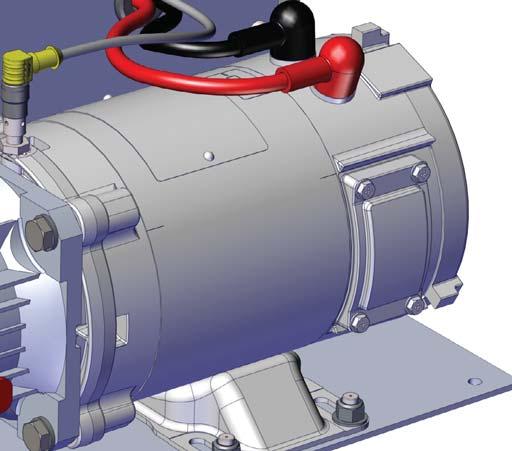
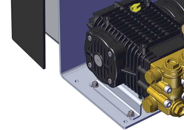
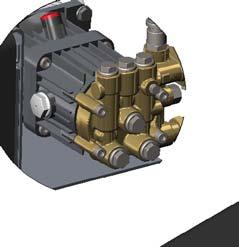
12 AQUIS 1.5 Components Feature Description 1 Oil level window This shows the oil level in the pump. 2 Cover This covers the control box and terminal strip. 3 Pump This is the pump assembly. 4 Vented oil cap This is cap replaces the shipping cap. 5 Motor This operates the pump. 6 Product sensor This senses the pump speed. 7 Pump outlet This outputs the concentrate. 8 Pump inlet This is the input for the concentrate supply. 9 Inject/Bypass valve This routes the concentrate to the injector or to an external container. 10 Mounting bracket This is the mounting bracket for foam pump assembly


13 AQUIS 3.0 Components Figure
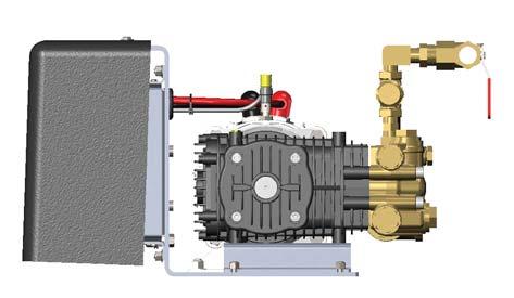
14 AQUIS 3.0 Components Feature Description 1 Oil level window This shows the oil level in the pump. 2 Cover This covers the control box and terminal strip. 3 Vented oil cap This is cap replaces the shipping cap. 4 Pump This is the pump assembly. 5 Motor This operates the pump. 6 Product sensor This senses the pump speed. 7 Pump inlet This is the input for the concentrate supply. 8 Pump outlet This outputs the concentrate. 9 Inject/Bypass valve This routes the concentrate to the injector or to an external container. 10 Mounting bracket This is the mounting bracket for foam pump assembly


15 AQUIS 1.5 and 3.0 Under the Cover Figure
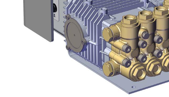
16 AQUIS 1.5 and 3.0 Under the Cover Feature Description 1 Accessory terminal strip This connects accessories to the control box. 2 Circuit breaker This prevents over-current. 3 Control box This houses the electric components. 4 Flowmeter connection 5 HMI/OIT connection This connects the controller to the HMI or OIT. 6 USB connection This connects control box to upgrade equipment. 7 Fuse housing This is the fuse location


17 AQUIS 6.0 Components Figure
18 AQUIS 6.0 Components Feature Description 1 Oil level window This shows the oil level in the pump. 2 Cover This covers the control box and terminal strip. 3 Pump This is the pump assembly. 4 Vented oil cap This is cap replaces the shipping cap. 5 Motor This operates the pump. 6 Product sensor This senses the pump speed. 7 Pump outlet This outputs the concentrate. 8 Pump inlet This is the input for the concentrate supply. 9 Inject/Bypass valve This routes the concentrate to the injector or to an external container. 10 Mounting bracket This is the mounting bracket for foam pump assembly


19 AQUIS 6.0 Under the Cover Figure
20 AQUIS 6.0 Under the Cover Feature Description 1 Accessory terminal strip This connects accessories to the control box. 2 Fuse housing This is the fuse location. 3 Circuit breaker This prevents over-current. 4 HMI/OIT connection This connects the controller to the HMI or OIT. 5 Flowmeter connection 6 Control box This houses the electric components. 7 USB connection This connects control box to upgrade equipment


21 Overview Diagram Typical 1 2 Note:
22 System Overview The following information describes the components the are used in a typical foam system setup. Your application may not include all, or contain additional components than the ones described below. Contact Waterous for more information. Component/Accessory 1 OIT or HMI The operator interface terminal (OIT) or a human machine interface (HMI) controls the foam system, an HMI when you use it with a ONE STEP or an Eclipse GEN 2.0 CAFSystem. 2 OIT/HMI cable This cable connects the OIT or HMI to the control box. 3 Tank level sensor wire This wire connects the level sensor to the control box. 4 Tank level sensor This sensor alerts the operator when the supply reaches a predetermined level in the supply tank. It is available as a horizontal or vertical mount. 5 Supply tank The supply tank contains the foam concentrate. 6 Tank shutoff valve The shutoff valve stops the concentrate from transferring into the supply hose. 7 Supply tank hose The supply hose transfers the concentrate from the supply tank to the pump. 8 9 Foam pump The foam pump transfers pressurized concentrate from the supply tank into the waterway. 10 Inject/bypass valve The inject/bypass valve directs the concentrate into the waterway, or removes it from the foam system. 11 Injector hose This hose transfers the concentrate from the pump to the injector. 12 Injector check valve This valve is installed in-line with the injector hose and prevents the concentrate from reversing direction. 13 Flowmeter sensor cable 14 Flowmeter tee 15 Master waterway check valve with injector This valve is installed in-line with the waterway and prevents the concentrate from reversing direction. The injector is installed on the valve and directs the concentrate into the waterway. 16 Foam manifold 17 Waterway supply line 18 Foam solution 19 Bypass hose The bypass hose transfers the concentrate from the pump to an external container. 20 Drain line Drain lines are provided by the apparatus manufacture and are used to drain your system


23 Dual Tank System Overview Optional Note:
24 Dual Tank System Overview Optional most applications. Contact Waterous for more information. Component/Accessory 1 Dual tank controller This controller switches the source that supplies concentrate to the pump. 2 Dual tank signal wire This cable connects the dual tank controller to the control box on the pump. 3 Tank A sensor cable This cable connects the tank A sensor to the control box. 4 Tank A level sensor This sensor alerts the operator when the concentrate reaches a predetermined level in tank A. This sensor is 5 Tank A This tank is part of the apparatus and holds the foam concentrate. 6 Tank B sensor cable This cable connects the tank B sensor to the control box. 7 Tank B level sensor This sensor alerts the operator when the concentrate reaches a predetermined level in tank B. This sensor is 8 Tank B This is added to the apparatus to provide a secondary supply of foam concentrate. 9 Tank B shutoff valve 10 Tank B supply hose This hose supplies concentrate between tank B supply and the electric valve. 11 Tank A shutoff valve 12 Tank A supply hose This hose supplies concentrate between tank A supply and the electric valve. 13 Tank A wye with strainer 14 Tank B wye with strainer 15 Tank A check valve 3/4 or 1 inch NPT This check valve is installed in-line with the tank A supply hose. 16 Tank B check valve 3/4 or 1 inch NPT This check valve is installed in-line with the tank B supply hose 17 Electric valve This valve determines which tank supplies the concentrate. 18 Flush system supply hose 19 Flush system wye with strainer 20 Flush check valve 3/4 or 1 inch NPT 21 Concentrate supply hose This hose connects the electric valve to the pump. 22 Electric valve cable This cable connects the electric valve to the dual tank controller. 23 Foam pump The foam pump transfers pressurized concentrate from the supply tank into the injector. Note: 24 88


25 Flush System Overview Optional
26 Flush Kit Overview Optional Component/Accessory 1 Foam pump The foam pump transfers pressurized concentrate from the supply tank into the injector. 2 Supply tank The supply tank contains the foam concentrate. 3 Tank shutoff valve The shutoff valve stops the concentrate from transferring into the supply hose. 4 3-Way tee valve 5 Note: 6 End cap 26 88
27 Component Overview The AQUIS foam proportioning system injects a foam concentrate into the waterway to create a solution that is delivered to the apparatus discharge lines. The AQUIS system consists of many components that control and distribute the and how they are used in the system. Hose Lines and Fittings Hose lines distribute the concentrate between the foam system components. Hoses are not supplied in this kit. Contact Waterous for more information. Supply Hose The supply hose routes the concentrate from the supply tank to pump. Contact Waterous for information about obtaining hose lines or you can source them locally. Inject Hose The inject hose routes the concentrate from the pump to the injector. Fittings Fittings connect the hoses to the various components in the system. Bypass Hose The bypass hose routes the concentrate from the inject/bypass valve to outside the apparatus. Pump Mounting Hardware The mounting hardware is required to secure the pump assembly to the apparatus. The hardware is not supplied with the kit. Source the Figure 25, Figure 26, and Figure 27. Power Cables Power cables bring power to the pump. Make sure that you use the same length and gauge for both the positive and the ground cable. The cables are not supplied in this kit. Source power cables from a local supplier. Refer to "Connecting the Power Supply" on page 59 Concentrate Tank The concentrate tank holds the concentrate until it is required. OIT/HMI Cable This cable connects the OIT or HMI to the control box (Figure 3 and Figure 5). This cable is an M12, 8-pin connector. Flowmeter Cable Figure 3 and Figure 5). This cable is an M12, 5-pin connector. Cable Extension cable. Contact Waterous for information about obtaining extension cables. Cables are available in a 3 and 6 meter lengths


28 USB Port The USB port is used to install program updates to the controller. It is a USB type B connector to connect to the control box (Figure 3 and Figure 5). Supply Tank Level Sensor This sensor alerts you when the concentrate reaches a predetermined level in the supply tank. A sensor not supplied in this kit. Contact Waterous for information about obtaining a sensor. Supply Tank Shutoff Valve Figure 8). The valve is an optional component available through Waterous. A supply tank shutoff valve is required per NFPA. Horizontal Sensor Vertical Sensor Figure 6 Figure 7 Supply Tank Level Sensor Cable This cable connects the level sensor to the control box. It is 2 bare wires, without connectors. Wye Fitting with Strainer Figure 8 foam system (Figure 9). It is available in 3/4 inch and 1 inch NPT. Figure
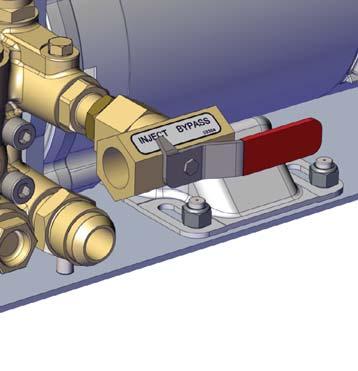
 to manually direct the concentrate as follows: Rotate the handle to the inject position to create a foam solution.")
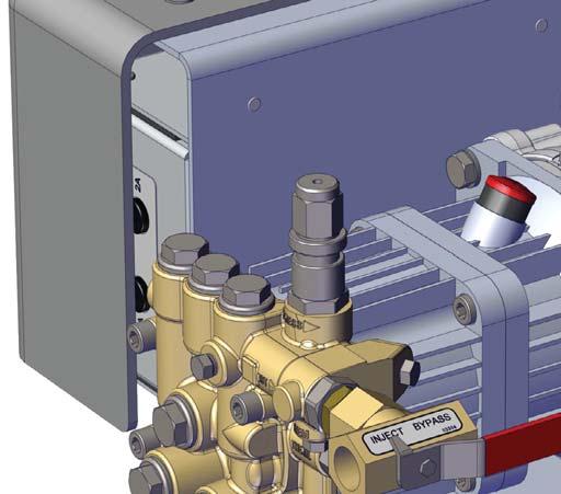
29 Concentrate Inject Check Valve from entering the concentrate hose (Figure 10). The valve is 3/8 inch NPT. Inject/Bypass Valve Use the inject/bypass valve (Figure 12) to manually direct the concentrate as follows: Rotate the handle to the inject position to create a foam solution. Rotate the handle to the bypass position to direct the concentrate out of the system. Figure 10 Flowmeter Figure 11). Figure Flowmeter 2. Cable 3. Paddlewheel Figure
 and FNPT (1-1/2 inches) 2-1/2-inch tee Inlet/Outlet: 3-inch tee Inlet/Outlet:")
30 Flowmeter Tee Figure 13) Flowmeter 2. Tee body Figure 13 2-inch tee Inlet/Outlet: Combination Victaulic (2 inches) and FNPT (1-1/2 inches) 2-1/2-inch tee Inlet/Outlet: 3-inch tee Inlet/Outlet: Combination Victaulic (2-1/2 inches) and FNPT (2 inches) Combination Victaulic (3 inches) and FNPT (2-1/2 inches) 30 88
 Outlet: Victaulic (2 inches) 2-1/2-inch valve Inlet: Victaulic (2-1/2 inches) Outlet: Victaulic (2-1/2 inches) 3-inch valve Inlet: Victaulic (3 inches) Outlet: Victaulic (3")
31 Master Waterway Check Valve (Figure /2-inch valve Inlet: Victaulic (1-1/2 inches) FNPT (1-1/2 inches) Outlet: Combination: Victaulic (2 inches) and FNPT (1-1/2 inches) 2-inch valve Inlet: Victaulic (2 inches) Outlet: Victaulic (2 inches) 2-1/2-inch valve Inlet: Victaulic (2-1/2 inches) Outlet: Victaulic (2-1/2 inches) 3-inch valve Inlet: Victaulic (3 inches) Outlet: Victaulic (3 inches) Victaulic (2 inches) FNPT (2 inches) Victaulic (2-1/2 inches) FNPT (2-1/2 inches) Victaulic (3 inches) FNPT (3 inches) Concentrate Injector solution in the apparatus (Figure 14). Note: Drain Port The drain port on the check valve allows the unused solution to empty through a dedicated line after use (Figure 15) Drain port 1 Figure Check valve 2. Injector Figure
. 1 Concentrate Injector Figure 16).")
.")
")
 Combination: Victaulic (3 inches) and FNPT (2-1/2")
32 Foam Manifold The foam manifold combines the concentrate injector, waterway check valve Figure 16). 1 Concentrate Injector Figure 16). Drain Port The drain port on the foam manifold allows the unused mixture to empty through a dedicated line after use (Figure 17) Injector 2. Flowmeter 3. Manifold Figure 16 Inlet/Outlet Combination: Victaulic (2 inches) and FNPT (1-1/2 inches) Combination: Victaulic (2-1/2 inches) and FNPT (2 inches) Combination: Victaulic (3 inches) and FNPT (2-1/2 inches) 1 1. Drain Figure
, the valve opens and the concentrate is routed from the output side of the pump to the input side of the pump.")

33 Pressure Regulator Valve This valve is set at the factory to bypass at 450 psi (31 bar). When the pressure reaches 450 psi (31 bar), the valve opens and the concentrate is routed from the output side of the pump to the input side of the pump. High Pressure Liquid ejected at high pressure can cause serious injury. Do not operate beyond recommended pressure. Figure 18 Do not tamper with the pressure regulator valve or operate the pump with a damaged pressure regulator valve. Use Figure 18 to locate the regulator valve on the AQUIS 1.5. Use Figure 19 to locate the regulator valve on the AQUIS 3.0. Use Figure 20 to locate the regulator valve on the AQUIS 6.0. Figure Figure 20

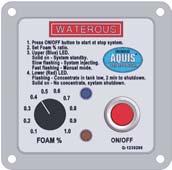
34 Operator Interface Terminal (OIT) The OIT enables or disables the foam system operation and adjusts the amount of concentrate that is injected into the waterway. It is available in digital and manual versions. Digital OIT The digital OIT (Figure 21) communicates with the pump controller to perform the following functions: Push button control of foam proportioning rate from 0.1% to 1.0% in 0.1 increments and 3% to 6% depending on the concentrate. LED displayed warning of low concentrate supply. Indicating light for A and B tank when dual supply tanks are installed. Manual operating mode for backup. Manual OIT The manual OIT (Figure 22) communicates with the pump controller to perform the following functions: Rotary dial control of foam proportioning rates from 0.1% to 1.0% in Low supply warning. 1. Press ON/OFF button to start or stop system. 2. Set Foam % ratio. 3. Upper (Blue) LED: Solid on - System standby. Slow flashing - System injecting. Fast flashing - Manual mode. 4. Lower (Red) LED: Flashing - Concentrate in tank low, 2 min to shutdown. Solid on - No concentrate, system shutdown. FOAM % ON/OFF Q Figure 22 Figure


35 Accessory Terminal Strip The terminal strip adds accessories and functionality to the pump. The terminal strip (Figure 24) is located under the cover on the controller (Figure 23). Description Figure 23 Figure 24 Comments 1 Auto run Enable Apply +Vdc to terminal 1 to enable the foam system. This allows you to operate the pump remotely or simultaneously with other equipment. 2 Tank level sensor tank B Connect one wire from the level sensor that is in tank B to terminal 2 and the other to terminal 5 or 8. This sensor alerts you when the concentrate reaches a predetermined level. 3 Tank level sensor tank A Connect one wire from the level sensor that is in tank A to terminal 3 and the other to terminal 5 or 8. This sensor alerts you when the concentrate reaches a predetermined level. 4 Tank B selected enable 5 Supply tank level sensor ground Ground terminal for the tank level sensors. 6 Not used Not used 7 Overboard foam pick-up or Prime the pump enable Connect the wire from overboard foam pickup switch. This allows you to enable a remote pick-up pump for priming the pump. 8 Supply tank level sensor ground Ground terminal for the tank level sensors
36 Installation Precautions The foam system is intended to be installed by a person or persons with the basic knowledge of installing similar equipment. Contact Waterous with questions about installing the foam system. Disconnecting the Frame Ground The foam system uses a frame ground to operate. Performing high voltage or high current operations, while the foam system is connected to the frame, can damage the electronics in the control box. High Current NOTICE High current from welding or jump start can damage electronic components. Disconnect all ground wire connections before jumping or welding. Modifying the Foam System The foam system components are designed to operate mounted to the mounting bracket. Removing the components from the mounting bracket (Figure 1, Figure 2 and Figure 3) and installing them independently, can damage the components, and will void your warranty. Modification NOTICE Modifying the equipment can damage components and void your warranty. Do not modify the foam system. Do not modify the foam system or any of its components. Doing so will void your warranty. Avoid damaging the electronics in the control box. Disconnect the frame ground before jump starting, welding, plasma cutting or conducting other high voltage or high current operations to the apparatus


37 AQUIS 1.5 Dimensions Inject/Bypass Valve 1/2 FNPT Foam Injection Out 1/2 FNPT Bypass Out Mounting Holes Oil Fill #12 MJIC Foam Supply In Sight Glass 1/2 FNPT Foam Injection Out 1/2 FNPT Bypass Out #12 MJIC Foam Supply In Figure


38 AQUIS 3.0 Dimensions #12 MJIC Foam Supply In Inject/Bypass Valve 1/2 FNPT Foam Injection Out 1/2 FNPT Bypass Out Mounting Holes Oil Fill/Dipstick Sight Glass 1/2 FNPT Bypass Out 1/2 FNPT Foam Injection Out #12 MJIC Foam Supply In Figure


39 AQUIS 6.0 Dimensions Inject/Bypass Valve 1 FNPT Foam Supply In 1/2 FNPT Foam Injection Out 1/2 FNPT Bypass Out Mounting Holes Oil Fill/Dipstick Sight Glass 1/2 FNPT Foam Injection Out 1/2 FNPT Bypass Out 1 FNPT Foam Supply In Figure
40 Digital OIT Dimensions Panel Cutout Use the self-tapping screws included to secure the OIT to the panel. Figure

41 Digital OIT Instruction Plate Dimensions Panel Hole Cutout Figure

42 Manual OIT Dimensions Panel Hole Cutout Figure

43 Foam Tee Dimensions Figure

44 Foam Manifold Dimensions Figure

45 3 Inch Check Valve Victaulic x FNPT Dimensions mm 7.95mm 15.88mm 76.20mm mm mm 76.20mm 84.94mm 88.90mm 73.85mm mm 83.49mm mm 55mm mm 98.87mm 55mm mm Figure

46 3 Inch Check Valve Victaulic x Victaulic Dimensions mm 76.20mm mm mm 76.20mm 73.85mm 88.90mm 84.94mm mm 84.94mm 88.90mm 83.49mm 7.95mm 7.95mm 15.88mm 15.88mm mm 55mm mm 98.87mm 55mm mm Figure
47 2-1/2 Inch Check Valve Victaulic x FNPT Dimensions mm mm mm mm 69.85mm 69.85mm 63.50mm mm 69.09mm 73.15mm 75.29mm 15.88mm 7.92mm 96.54mm 48.27mm 92.52mm 48.27mm 96.54mm Figure
48 2-1/2 Inch Check Valve Victaulic x Victaulic Dimensions 7.92mm mm 7.92mm 15.88mm 15.88mm mm 69.09mm 96.54mm 48.27mm 92.52mm mm 73.15mm mm 69.85mm 69.85mm 63.50mm 73.15mm 69.09mm mm 75.29mm 48.27mm 96.54mm Figure

49 2 Inch Check Valve Victaulic x FNPT Dimensions mm mm 96.58mm 63.50mm 63.50mm 57.15mm 60.33mm 51.82mm 61.11mm mm mm 80.82mm 40.41mm 86.17mm 15.88mm 40.41mm 7.95mm 80.82mm Figure


50 2 Inch Check Valve Victaulic x Victaulic Dimensions mm 63.50mm mm 96.58mm 63.50mm 57.15mm 60.33mm 60.33mm 57.15mm 15.88mm 7.95mm mm 80.82mm 40.41mm 86.17mm 54.17mm 61.11mm mm 40.41mm 15.88mm 80.82mm 7.95mm Figure


51 1-1/2 Inch Check Valve Victaulic/FNPT x FNPT Dimensions Figure

52 1-1/2 Inch Check Valve Victaulic/FNPT x Victaulic Dimensions Figure
53 Preparing for the Install Consider the information below before you begin installing the foam system. Determine the install location for the components, consider wire and hose routing, mounting locations and maintenance requirements. Locate the pump as close to the supply source as possible. Install it in a clean space where it can be easily inspected and maintained. Allow room for checking the oil level, changing the oil and general servicing. Do not remove the components from the bracket and install them directly to the apparatus. Doing so will void your warranty. Position the pump assembly in an area that is protected from road debris and excessive heat buildup. Be aware that most water tank manufacturers incorporate a foam tank into the booster tank. When specifying an integrated foam tank, ensure that you include the installation of the optional low tank level sensor as well as the foam suction connections and tank drainage according to NFPA guidelines. Determine a location for the OIT on the operator panel of the equipment. Installing the Vented Oil Cap NOTICE Before operating the AQUIS Foam Proportioning System: Check the foam pump oil level and fill if necessary. Remove the foam pump shipping plug and replace it with this vented oil cap. Refer to instruction F for detailed information. The foam system ships with a non-vented oil cap. Replace it with the vented oil cap that is provided before you operate the pump. 1. Locate and remove the oil cap that was shipped with the pump (Figure 1, Figure 2 and Figure 4). 2. Check the oil level. Refer to: "Checking the Oil Level" on page Add oil if necessary. Refer to: "Adding Oil" on page Install the vented oil cap that is supplied with the pump kit (Figure 1, Figure 2 and Figure 4)
54 Determining the Pump Assembly Location Use the following guidelines to determine a location to mount the pump assembly: The pump assembly must be mounted on a horizontal surface. The surface must withstand the pump assembly operation. Install the pump assembly where it has minimal exposure to excessive dirt, road debris and heat buildup. The pump is capable of a 1 meter draft of foam concentrate, however, a gravity feed setup is preferred. Locating the Pump Assembly Mounting Holes Locate and drill the holes for the mounting bracket. Use Figure 25 to determine the hole dimensions for AQUIS 1.5. Use Figure 26 to determine the hole dimensions for AQUIS 3.0. Use Figure 27 to determine the hole dimensions for AQUIS 6.0. Locating the OIT Mounting Holes Locate and drill the mounting and opening holes for the OIT. Use Figure 28 to determine the dimensions for the digital OIT opening. Use Figure 30 to determine the dimensions for the manual OIT opening. Installing the Pump Assembly The foam system components are designed to operate as installed on the mounting bracket (Figure 1, Figure 2 and Figure 3). Do not remove the components from the mounting bracket and install them independently. Doing so can damage the components, and will void your warranty. Modification NOTICE Modifying the equipment can damage components and void your warranty. Do not modify the foam system. Do not remove the components from the bracket and install them directly to the apparatus. Doing so will void your warranty. 1. Align the holes in the mounting bracket to the holes that you drilled in apparatus. 2. Use the appropriate hardware to secure the pump to the apparatus. Refer to Figure 25, Figure 26 and, Figure 26 to determine the hardware that you need


. Figure 41 5.")
55 Installing the OIT 1. Locate one end of the M12, 8-pin cable. 2. Align the pins and key in the plug to the connector. 3. Secure the plug into the connector. Note: 4. Ensure that there is a minimum of 5 inches (125 mm) behind the panel opening to give the cable enough room to bend (Figure 41). Connecting M12 Cables to the Control Box 1. Remove the cover. Refer to: "Removing the Cover" on page Align the pins and key in the plug to the connector. Note: 3. Secure the plug into the connector. 4. Connect the cable to the appropriate connector on the control box (Figure 42). Figure Use the included hardware (digital OIT) or locally source the appropriate hardware (manual OIT) to secure the OIT to the panel. 6. Route the cable to the control box. 7. Connect the cable to the control box. Refer to: "Connecting M12 Cables to the Control Box" on page 55. Figure

56 1. (Figure 43). Figure Figure 43). 3. Use cable ties to secure the cable to the apparatus. Note: Note: 4. Install the cover. Refer to: "Installing the Cover" on page 62. Installing the Master Waterway Check Valve Note: "Overview Diagram Typical" on page Use the victaulic or FNPT connections to install the waterway check valve in-line with the waterway. 2. Install the inlet side of the waterway check valve towards the water pump. Installing the Foam Manifold 1 Note: "Overview Diagram Typical" on page Outlet 2. Inlet Figure (Figure 46) Outlet 3. Inlet Figure

57 2. Install the inlet side of the manifold towards the water pump. Important: (Figure 46) Top Installing the Flowmeter Tee 1. (Figure 48). Figure Connect the 3 meter, M12, 4-pin extension cable to the cable attached to Note: Note: 4. Route the cable to the control box meter, M12, 4-pin extension cable Connect the cable to the control box. Refer to: "Connecting M12 Cables to the Control Box" on page /2-inch tee shown Figure Note: 3. Connect the 3 meter, M12, 4-pin extension cable to the cable attached to Note: Note: 4. Route the cable to the control box
58 5. Connect the cable to the control box. Refer to: "Connecting M12 Cables to the Control Box" on page 55. Important: (Figure 48) Top Figure 48 Installing the Supply Hose The supply hose routes the concentrate from the supply tank to pump. Refer to the "Overview Diagram Typical" on page 21 for the instructions in this Minimum 3/4 inch inside diameter for AQUIS 1.5 and 3.0 Minimum 1 inch inside diameter for AQUIS 6.0 Minimum 23 inhg (0.78 bar) of vacuum Maximum 50 psi (3.45 bar) of pressure Reinforced clear wall as required by NFPA 1. Route and connect the supply hose from the supply tank shutoff valve to the foam pump intake. Note: 2. Note: Note: Note: Installing the Injector Hose The injector hose routes the concentrate from the foam pump to the injector. Refer to the "Overview Diagram Typical" on page 21 for the instructions Minimum 3/8 inch inside diameter AQUIS 1.5 and AQUIS 3.0 Minimum 1/2 inch inside diameter AQUIS 6.0 Minimum 450 psi (31 bar) of pressure 1. Connect one end of the hose to the output on the foam pump. 2. Connect the other end of the hose to the concentrate injector check valve. 3. Use cable ties to secure the hoses to the apparatus. Note: Note: Note: Connecting the Bypass Hose Refer to "Overview Diagram Typical" on page 21 for the instructions in Minimum 3/8 inch inside diameter. Long enough to reach a container outside the apparatus and can be coiled when not in use. 1. Connect the hose to the bypass port on the inject/bypass valve. 2. Secure the bypass hose until it is used. Note: Note: Note: Fittings Fittings connect the hoses to the various components in the system. The Compatible with the foam concentrate Corrosion resistant 58 88
59 Removing the Cover 1. Remove the 3 screws and washers that are used to secure the cover to the frame and set them aside (Figure 49) Connecting the Power Supply High Current Current can cause serious injury or death. Disconnect the power before servicing the pump. 1. Screw 2. Washer 3. Cover 2. Remove the cover and set it aside. Figure 49 Read and understand the following statements before continuing: The pump motor uses 30 A to 100 A of current to operate. Electrical current is dangerous and can cause serious injury or death. Do not attempt to connect the pump motor to the power source if you have not been trained and understand the safety practices needed to install devices requiring 30 A to 100 A to operate. Model Voltage Amps AQUIS Vdc 50 A 24 Vdc 30 A AQUIS Vdc 80 A 24 Vdc 50 A AQUIS Vdc 100 A 24 Vdc 80 A 59 88

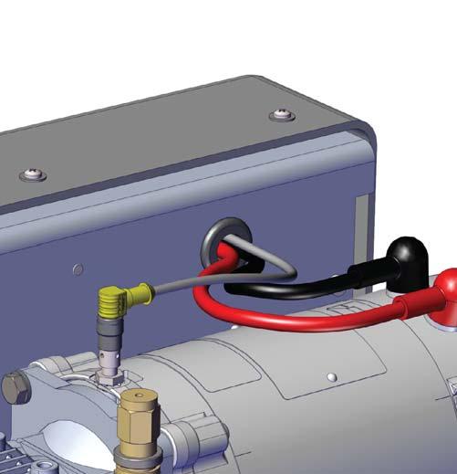
60 following tables are calculated using the SAE J1128 standard with a 2% drop. 12 V Amps Length of Wire 10 ft 15 ft 20 ft 25 ft 30 ft 50 A 6 AWG 4 AWG 2 AWG 2 AWG 2 AWG 80 A 4 AWG 2 AWG 1 AWG 0 AWG 0 AWG 100 A 2 AWG 2 AWG 0 AWG 00 AWG 00 AWG 4. Connect the other end of the positive (+) cable to the positive (+) post of the foam pump (Figure 50) V Amps Length of Wire 10 ft 15 ft 20 ft 25 ft 30 ft 30 A 12 AWG 10 AWG 8 AWG 8 AWG 6 AWG 50 A 8 AWG 8 AWG 6 AWG 4 AWG 4 AWG 80 A 6 AWG 6 AWG 4 AWG 2 AWG 2 AWG Important: Important: 1. Remove the cover. Refer to: "Removing the Cover" on page Route the positive (+) cable from the power source to the foam pump. 3. Connect one end of the positive (+) cable to the Vdc source. 1. Positive (+) post 2. Negative ( ) post Figure Connect the negative ( ) post to the frame ground. 6. Install the cover. Refer to: "Installing the Cover" on page
.")
. Figure 52 Figure 51 4. Install the cover. Refer to \"Installing the Cover\" on page 62. 5. (Figure 43). 6. Figure 43).")
61 Installing the Tank Level Sensor Cable 1. Connect the sensor wires to the wires on the foam concentrate sensor. 2. Remove the cover. Refer to "Removing the Cover" on page Secure one wire to terminal 3 and the other wire to terminal 5 on the terminal strip (Figure 51). Note: Installing the Wye Fitting with Strainer it may be remotely mounted, or mounted to the intake of the foam pump. 1. for maintenance. 2. direction of the foam concentrate (Figure 52). Figure 52 Figure Install the cover. Refer to "Installing the Cover" on page (Figure 43). 6. Figure 43). Note: 3. Make sure that the stainer feature is pointing down

. Figure 53 2. Installing the Cover 1.")
. 1 1.")
62 Installing the Concentrate Inject Check Valve 1. concentrate (Figure 53). Installing the Drain Lines Install a dedicated line to the drain port on the check valve or manifold to remove the unused solution and to relieve pressure (Figure 55 and Figure 56). Figure Installing the Cover 1. Locate the 3 screws and washers that you removed from the cover. 2. Use the 3 screws and washers to secure the cover to the bracket (Figure 54) Drain port Figure 55 Figure Screw 2. Washer 3. Cover Figure
63 Calibrating Manual OIT Flow rate US gallons 1. Rotate the (FOAM % dial) to Press and hold the (ON/OFF button) for 6 seconds Press the The calibrated. The the calibration process. The value was not changed. Default mix percentage 0.1% 0.2% 0.3% 0.4%.05% 0.6% 0.7% 0.8% 0.9% 1.0% Calibrating and Setup Digital OIT Entering the Calibration/Setup Mode 1. Press and hold the (SELECT button). 2. After 5 seconds, the (5 second value) is displayed. 3. Continue holding the (SELECT button) and then press the (up and down buttons) simultaneously. 4. The (calibration value) is displayed, then after 2 seconds the (function value) displays. 5. Press the or (up or down button) to navigate to the desired parameter. 6. Press the (FOAM button) to save the value and exit the calibration and etup mode. Note: 63 88
64 Editing the Default Mix Percentage F1 1. Enter the calibration/setup mode. Refer to: "Entering the Calibration/Setup Mode" on page 63. Editing the Units of Measure F2 1. Enter the calibration/setup mode. Refer to: "Entering the Calibration/Setup Mode" on page Navigate to (F1 parameter). 2. Navigate to (F2 parameter). 3. Press the (SELECT button) to edit the parameter. 3. Press the (SELECT button) to edit the parameter. 4. Press the or (up or down button) to display the desired foam percent. The value displayed is between (0.1 percent) to (1.0 percent). 5. Press the (SELECT button) to select the displayed value. 6. Press the (FOAM button) to save the value and exit the calibration and etup mode. 4. Press the or (up or down button) to display the desired unit of measure from the following choices: US gallon Imperial gallon Metric liter Liters per second 5. Press the (SELECT button) to select the displayed value. 6. Press the (FOAM button) to save the value and exit the calibration and etup mode
65 Calibrating the Flow Rate F3 Note: 1. Use your preferred method of measurement to determine the actual 2. Enter the calibration/setup mode. Refer to: "Entering the Calibration/Setup Mode" on page 63. Enabling System Lockout F4 Note: 1. Enter the calibration/setup mode. Refer to: "Entering the Calibration/Setup Mode" on page Navigate to (F4 parameter). 3. Navigate to (F3 parameter). 3. Press the (select button) to edit the parameter. The 4. Press the (SELECT button) to enter the parameter. 5. If the value that you measured and the displayed value match, press the (FOAM button) to save the value and exit the calibration and etup mode. If the value that you measured and the displayed value do not match, press or (up or down button) to adjust the display value to match the value that you measured. When the (enable setting) is displayed. 4. Use the (up button) to display the (lock setting). 5. Press the (SELECT button) to return to the (F4 parameter). 6. Press the (FOAM button) to save the value and exit the calibration and etup mode. Note: 6. Press the (SELECT button) to return to the (F3 parameter). 7. Press the (FOAM button) to save the value and exit the calibration and etup mode
66 Selecting the Concentrate Source F5 1. Enter the calibration/setup mode. Refer to: "Entering the Calibration/Setup Mode" on page Navigate to (F5 parameter). 3. Press the (SELECT button) to edit the parameter. 4. Use the or (up or down button) to display the desired foam tank pairing: Select (AA) when you source from a single tank that supplies A foam or when you source from 2 tanks that supply A foam. The proportioning value for this setting is between 0.1% to 1.0% for both tanks. Select (Ab) when you source from 2 tanks that supply A foam from one tank (tank A) and B foam from the other tank (tank B). The proportioning value for this setting is between 0.1% to 1.0% for the A foam tank and 1.0%, 3.0% and, 6.0% from the B foam tank. calibration and etup mode. Simulating Water Flow F6 Use this mode to test and verify the foam system operation. This function is available for the AQUIS 1.5 with digital head, AQUIS 3.0 and AQUIS Enter the calibration/setup mode. Refer to: "Entering the Calibration/Setup Mode" on page Navigate to (F6 parameter). 3. Press the (SELECT button) to edit the parameter. 4. Use the or (up or down button) to display the desired Flow Rate Settings AQUIS AQUIS AQUIS Select (bb) when you source from a single tank that supplies B foam or when you source from 2 tanks that supply B foam. The proportioning value for this setting is 1.0%, 3.0% or, 6.0% for both tanks. Select (AF) when you source from a 2 tanks that supply combination A/B foam. The proportioning value for this setting is between 0.1% to 1.0%, 3.0% or, 6.0% for both tanks. 5. Press the (SELECT button) to return to the (F5 parameter). 5. Press the (SELECT button) to save the value. 6. Position the inject/bypass valve to bypass. Refer to: "Operating the Inject/Bypass Valve" on page Press the (FOAM button) to start the pump. Note: Press the (FOAM button) to save the value and exit the Press the (FOAM button) to stop the pump. 10. Measure the volume of concentrate.
67 Flow rate US gallons 11. Default mix percentage 0.1% 0.2% 0.3% 0.4%.05% 0.6% 0.7% 0.8% 0.9% 1.0% Enter the calibration mode. Refer to: "Entering the Calibration/Setup Mode" on page Navigate to (F6 parameter). 14. Press the (SELECT button) to edit the parameter. Setting Default Mix Percent for B Foam F7 1. Enter the calibration/setup mode. Refer to: "Entering the Calibration/Setup Mode" on page Navigate to (F7 parameter). 3. Press the (SELECT button) to edit the parameter. 4. Use the or (up or down button) to display the desired foam percent. The value displayed is (1.0 percent), (3.0 percent), or (6.0 percent). 15. Use the (down button) to display the (zero 16. Press the (SELECT button) to save the value. 17. Press the (FOAM button) to save the value and exit the calibration and etup mode. 5. Press the (SELECT button) to select the displayed value. 6. Press the (FOAM button) to save the value and exit the calibration and etup mode. Auto Run Mode Apply voltage (+12 Vdc or +24 Vdc) to terminal 1 on the accessory terminal strip to enable run mode. Refer to: "Accessory Terminal Strip" on page
68 Operating Precautions The foam system is intended to be operated by a person, or persons, with the basic knowledge of operating similar equipment. Contact Waterous with questions about operating the foam system. Be aware of the following precautions when using the foam system: Hot Liquid Certain operating conditions cause the solution temperature to reach and exceed 160 F (71 C). Hot Surface Components in the foam system may become hot during operation. Hot Surface Hot surface can burn you. Hot Liquid Hot liquid can scald you. Do not operate if the water temperature exceeds 160ºF (71ºC). Do not touch the surface during operation allow it to cool after operating. Do not touch the hot components and allow components to cool before handling. Avoid conditions the result it high temperature solution. Do not operate when solution temperature exceeds 160 F (71 C)
69 Operating the Manual OIT Operating in Normal Mode FOAM % dial to produce the desired mix. Starting and Stopping the Pump 1. Press ON/OFF button to start or stop system. 2. Set Foam % ratio. 3. Upper (Blue) LED: Solid on - System standby. Slow flashing - System injecting. Fast flashing - Manual mode. 4. Lower (Red) LED: Flashing - Concentrate in tank low, 2 min to shutdown. Solid on - No concentrate, system shutdown Press the (ON/OFF button) to start the pump and begin injecting concentrate into the waterway. 2. Press the (ON/OFF button) to stop the pump and end injecting concentrate into the waterway. Adjusting the Mix Ratio 1 Rotate the (FOAM % dial) to the desired percent of concentrate in the mix at the nozzle. 3 FOAM % ON/OFFF 4 Q Figure 57 Feature Description 1 Foam percent dial This dial adjust the percentage of concentrate injected into the waterway. 2 Blue LED The blue LED indicates the modes and status of the pump operation. 3 Red LED The red LED indicates the modes and status of the pump operation. 4 ON/OFF button The ON/OFF button enables and disables the foam operation
70 Operating in Manual Mode The foam system can operate in manual mode as required by the NFPA regulation. While in manual mode, the foam system injects concentrate into decrease the motor speed and FOAM % is controlled manually. High Pressure Liquid ejected at high pressure can cause serious injury. Do not operate beyond recommended pressure. Understanding the LED Indicators Blue LED Solid on The system is in standby mode. Flashing, slowly (1 Hz) The system is injecting the concentrate. Flashing, quickly (2 Hz) The system is in manual mode. Red LED Solid on No concentrate, the system is off line. Flashing The concentrate in the tank is low. Do not operate while all discharges or drains are closed. High pressure results and damages the foam system, its components. 1. Press and hold the (ON/OFF button) for 2 seconds. The blue indicator blinks at a faster (2 Hz) rate. 2. Turn the (FOAM % dial) to increase or decrease the motor speed. 3. Press the (ON/OFF button) to exit manual mode

71 Operating the Digital OIT 1 Mounting hardware The hardware mounts OIT to the apparatus. 2 FOAM button This button starts and stops the pump operation. 3 Display The display shows 4 characters that represent the value for the current mode. 4 Supply tank LED The supply tank LED shows the concentrate tank that is in operation. 5 Increase button This button increases the value in the display. 6 SELECT button This button selects the value in the display. 7 Display mode LED The display mode LED indicates what information that is currently display. 8 ON LED The ON LED indicates when the foam system is on, off, or in standby. 9 Decrease button This button decreases the value in the display Figure
72 Powering Up the OIT The apparatus manufacturer determines how the foam system powers up in your application. However, when power is applied to the foam system, the OIT Understanding the ON LED The (ON LED) indicates 3 states: Solid on The system is in standby mode waiting for a signal from the Flashing The system is injecting foam concentrate. Off The system is not enabled. Operating in Normal Mode the foam % value to produce the desired mix. Starting and Stopping the Pump 1. Press the (FOAM button) to start the foam system and begin injecting concentrate into the waterway. 2. Press the (FOAM button) to stop the foam system and end injecting concentrate into the waterway. Adjusting the Mix Percentage 3. Press the (SELECT button) until the PERCENT LED illuminates. 4. Press the (up button) to increase the percent by 0.1%. 5. Press the (down button) to decrease the percent by 0.1%. 6. The display returns to FLOW RATE after 10 seconds without use. Operating in Manual Mode The foam system can operate in manual mode as required by the NFPA regulation. While in manual mode, the foam system injects concentrate into High Pressure Liquid ejected at high pressure can cause serious injury. Do not operate beyond recommended pressure. Do not operate while all discharges or drains are closed. High pressure results and damages the foam system, its components. Enabling Manual Mode 1. Press the (SELECT button) until the WATER FLOW LED illuminates. 2. Press the (up and down buttons) simultaneously for 2 seconds. Note: 3. The percent LED illuminates. 4. The display shows the last value used. The pump is in manual mode
73 Operating and Disabling Manual Mode In manual mode you can start or stop the pump and increase or decrease the foam percent. 1. Press the (FOAM button) to pause the foam system. 2. Press the (up and down buttons) to adjust the amount of concentrate that is injected into the waterway. Press the (up button) to increase the value by 0.5. Press the (down button) to decrease the value by Press the (FOAM button) to start the pump. 4. Press the (up and down buttons) simultaneously to stop the pump and exit manual mode. Auto Run Mode If Equipped The foam system activates automatically when auto run mode is enabled and (FOAM button) to activate the system. Changing the Display Mode 1. Press the (SELECT button) to scroll though the following modes: and then back to WATER FLOW. Displaying Default Mix Percent 1. Press the (SELECT button) until the PERCENT LED illuminates. 2. Press the (up and down buttons) simultaneously. The value displayed is the default mix percent. Zeroing the Total Water Value 1. Press the (SELECT button) until the TOTAL WATER LED illuminates. 2. Press the (up and down buttons) simultaneously. The TOTAL WATER value is set to 0. Zeroing the Total Foam Value 1. Press the (SELECT button) until the total foam LED illuminates. 2. Press the (up and down buttons) simultaneously. The TOTAL FOAM value is set to 0. Displaying the Supply Tank Supply tank A LED is illuminated by default. Supply B tank LED is reserved for applications that include a B supply tank with a dual tank selector kit installed. The (supply tank LED) indicates tank that is supplying the concentrate. 2. Press and hold the (SELECT button) for 3 seconds to lock the display to the current mode
74 Operating the Inject/Bypass Valve Note: "Overview Diagram Typical" on page 21 Use the inject/bypass (Figure 59) valve to direct the concentrate to the injector port or the bypass hose. Flushing the Foam System Maintenance NOTICE Not following maintenance procedures can damage your equipment. Perform all maintenance procedures as required. Figure 59 Rotate the handle on the inject/bypass valve to the inject position to route the concentrate into the waterway and produce a solution. Rotate the handle on the inject/bypass valve to the bypass position to route the foam concentrate into the bypass hose. Draining the Foam System Follow the instructions from the apparatus manufacturer to drain the valve. Contact Waterous for more information. Leaving corrosive solution in the foam system damages the equipment. pump. Refer to the apparatus and/or concentrate manufacturer to determine a Flushing the AQUIS Foam System 1. Refer to the documentation provided by the apparatus manufacturer for more information. 2. Enable manual mode on the OIT. Refer to: Manual OIT "Operating in Manual Mode" on page 70. Digital OIT "Operating in Manual Mode" on page concentrate is removed

75 Maintenance Schedule Perform the following procedures at the recommended intervals. Operation Check the oil level Change the oil Inspect the mounting hardware Servicing the Oil Every 8 Hours X Every 50 Hours X X Every 500 Hours then every 500 hours. hours of use and then every 500 hours there after. Checking the Oil Level 1. Locate the oil level window to determine the oil level (Figure 1, Figure 2 and Figure 4). 2. Ensure that the oil level is centered in the window. 3. Add oil if necessary. Refer to: "Adding Oil" on page 76.Changing the Oil hours thereafter. Draining the Oil 1. Trip the circuit breaker. Refer to:"tripping and Resetting the Circuit Breaker" on page Remove the hardware that secure the pump to the mounting bracket and set them aside (Figure 60). Note: X High Pressure Liquid ejected at high pressure can cause serious injury. Drain the lines before servicing Hardware Figure Place a container under the pump that is large enough to collect all the oil that drains from the oil reserve.
. Adding Oil Note: 1. Remove the vented oil cap and set it aside (Figure 1, Figure 2,")
76 Loosen and remove the drain plug on the bottom of the pump (Figure 61). 1. Drain port 2. Drain plug Figure Allow the oil to drain. 6. Install the drain plug to the pump (Figure 61). 7. Use the hardware that you set aside to secure the pump to the mounting bracket (Figure 61). Adding Oil Note: 1. Remove the vented oil cap and set it aside (Figure 1, Figure 2,and Figure 4). 2. Use the chart below to determine the oil capacity of your model. Model Oil Capacity AQUIS oz (0.18 L) AQUIS oz (0.32 L) AQUIS oz (0.56 L) Use the sight window to determine the oil level in the reserve. Note: 5. Install the oil cap to the oil reserve. Completing the Oil Change 1. Set the circuit breaker to operating position. 2. Install the cover. Refer to: "Installing the Cover" on page

. 3.")
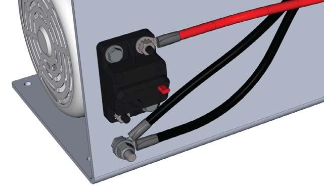
77 Replacing a Fuse Note: 1. Remove the cover. Refer to: "Removing the Cover" on page Trip the circuit breaker. Refer to:"tripping and Resetting the Circuit Breaker" on page Locate the fuse holder/cap on the control box and remove it. 4. Remove the fuse from the holder/cap. 5. NOTICE Equipment Damage Using the wrong fuse may damage the equipment. Only use the specified fuse rating. causes poor performance or damages the foam system. 6. Install the fuse holder/cap into the control box. 7. Install the cover. Refer to: "Installing the Cover" on page 62. Tripping and Resetting the Circuit Breaker 1. Remove the cover. Refer to: "Removing the Cover" on page Locate the circuit breaker (Figure 62). 3. Press the red button to trip the breaker. Note: Foam pump 2. Inject/discharge valve Figure Swing the black contact lever into operating position to reset the circuit breaker
. Inspecting the Hoses and Fittings Check the hoses for wear, deterioration, and leaks.")
78 Cleaning the Wye Fitting with Strainer 1. Close the shutoff valve at the supply tank. 2. Understand and follow the safety instructions from the foam concentrate manufacturer. 3. Place a container underneath the strainer to collect the concentrate that drains from the strainer. 4. Figure 63). Inspecting the Hoses and Fittings Check the hoses for wear, deterioration, and leaks. Inspect the Mounting Hardware Inspect the mounting hardware every 500 hours of use. Make sure the mounting hardware is free from oxidation. Make sure the mounting hardware secures the pump to the apparatus. Tighten if necessary Strainer 3. Cap Figure Flush the debris from the stainer Figure 63). 9. Open the shutoff valve at the supply
79 Trouble Shooting Chart Symptom Possible Cause Corrective Action The foam pump is operating but The pump loses prime. Excessive concentrate is being injected into the solution. injected into the solution. The pump runs at full speed whether the foam pump is on or off. The foam pump runs at full speed whenever the foam system is on. The green light on the OIT does not illuminate when the foam system is enabled. The foam system does not output the concentrate. The foam pump and OIT has power but does not inject concentrate when it is enabled. The foam pump is not primed. The concentrate tank is empty. The strainer is plugged. The check valve does not open. Air is entering the into the concentrate supply hose. The concentrate supply hose is blocked, collapsed, or too small. The speed sensor position is misaligned. The system is operating in manual mode. The foam system is out of calibration. The foam system is out of calibration. The controller is faulty. There is a bad ground between the controller and chassis. The LED has failed. The cables are not proper connected. There is a bad ground between the controller and chassis. Improper voltage. The power is not on. The pressure relief valve is set too low. Inject/bypass valve is set to the bypass position Prime the foam pump Add concentrate to the tank. Clean or replace the strainer. Clean or replace the check valve. Repair or replace deteriorated hose or improperly sealed Repair or replace the blocked, damaged, or improperly Align the speed sensor. Press the up and down buttons simultaneously. The controller requires reprogramming, contact Waterous. The controller requires reprogramming, contact Waterous. Contact Waterous to replace the controller. Repair or replace ground wire or ground connection. Contact Waterous for a replacement. Ensure that all the cables are properly connected. Repair or replace ground wire or ground connection. Check that the voltage suppled are correct. Turn on the power. Reset or replace the pressure relief valve. Set the valve to the inject position. Flow water through a foam capable discharge. Measuring for incorrect unit of measure setting in menu. Use the correct measurement method or change the unit of measure in the menu.
80 Trouble Shooting Chart Continued Symptom Possible Cause Corrective Action The OIT displays ncon. The concentrate supply tank is empty. Add concentrate to the tank. The concentrate level sensor is malfunctioning. Repair or replace the sensor or cable. The mix does not output from the nozzle as expected. The OIT does not light up. The green LED on the OIT does manifold. The OIT displays horizontal bars. The concentrate enters the water tank. The green LED does not light up but a value is displayed. The mix percentage is set too low. The foam system is not primed. Low foam volume. No power to the OIT. The master power on vehicle is not enabled. The circuit breaker switch has tripped. There is a communication error between the OIT and the controller. Concentrate was poured into the water tank. A check valve in the waterway is malfunctioning. The drain for the foam manifold is not isolated. The foam system is not on. Increase the mix percentage. Prime the foam system. Increase the mix percentage. Check the power cable to the controller and the OIT cable. Enable the master power. Reset the circuit breaker. Verify that the pins on the cable are not bent, replace the cable if they are damaged. Contact Waterous to replace the control box. Flush the water tank. Clean, clear, or replace check valve. Isolate the drain for the foam manifold. Press the foam button


81 AQUIS 1.5 and 3.0 Components Horizontal Mount No. Description 201 Adapter 3/8 MNPT x 3/8 JIC 202 Bushing reducer 1 x 1/2 inch 207 Black boot 208 Red boot 209 Gourmet 211 Z bracket 213 Pump spacer 214 Pump spacer 215 Ball valve 3 way 217 Product sensor 220 Electric motor 221 Control box 223 Foam pump 224 Circuit beaker No. Description 225 Screw 1/4-20 x 3/4 inch 226 Screw 3/8-16 x 2 inches 227 Screw 5/16-18 x 1-1/4 inches 228 Washer 1/4 inch 229 Washer 5/16 inch 230 Lock washer 3/8 inch 232 Washer # Locknut 5/ Locknut Nut 5/ Inject/bypass label 253 Cable tie AQUIS 1.5 and 3.0 Foam Pump Components Horizontal Mounting Bracket Left or Right Pump Mounting (AQUIS 3.0 Left Pump Mounting Shown) 81 88


82 AQUIS 1.5 and 3.0 Components Vertical Mount No. Description 201 Adapter 3/8 MNPT x 3/8 JIC 202 Bushing reducer 1 x 1/2 inch 207 Black boot 208 Red boot 209 Gourmet 211 Z bracket 212 Standoff 1/4-20 x 5 inches 213 Pump spacer 214 Sensor wheel 215 Ball valve 3 way 217 Product sensor 220 Electric motor 221 Control box 223 Foam Pump 224 Circuit beaker 225 Screw 1/4-20 x 5/8 inch 226 Screw 3/8-16 x 2 inches 227 Screw 5/16-18 x 1-1/4 inches 228 Washer 1/4 inch 229 Washer 5/16 inch 230 Lock washer 3/8 inch 232 Washer # Locknut 1/ Locknut 5/ Locknut Nut 5/ Inject/bypass valve AQUIS 1.5 and 3.0 Foam Pump Components Vertical Mounting Bracket 82 88


83 AQUIS 6.0 Components No. Description 207 Black boot 208 Red boot 209 Grommet 211 Z bracket 213 Pump spacer 215 Sensor wheel 217 Product sensor 220 Electric motor 221 Control box 223 Foam Pump 224 Circuit beaker 225 Screw 1/4-20 x 3/4 inch 226 Screw 3/8-16 x 2 inches 227 Screw 5/16-18 x 1-1/4 inches 228 Washer 1/4 inch 229 Washer 5/16 inch 230 Lock washer 3/8 inch 232 Washer # Locknut 5/ Locknut No. Description Nut 5/ Inject/bypass valve 239 Regulator valve 240 Support bracket Bypass hose 244 Adapter 3/8 MNPT x 3/8 JIC 245 Elbow 3/8 inch 246 Nipple pipe 1/2 x 3/8 inch 247 Nipple pipe 3/8 inch 248 Nipple pipe 1/2 NPT x 1-1/8 inch 249 Bushing reducer 1 x 1/2 inch 250 Screw x 14 mm 251 Washer 8 mm 252 Ground cable 253 Cable tie AQUIS 6.0 Foam Pump Components 83 88

 Vertical Mounting Bracket AQUIS 1.5, 3.0, and 6.")
84 AQUIS 1.5, 3.0 and 6.0 Complete Unit No. Description 100 Cover 101 Cover label 102 Screw x 1/2 inch 103 Washer # Screw 1/4-20 x 3/4 inch 105 Washer 1/4 inch 200 Foam pump assembly Horizontal Mounting Bracket (Left or Right Pump Mounting) Vertical Mounting Bracket AQUIS 1.5, 3.0, and 6.0 Foam Manifold Complete Unit (AQUIS 3.0 Left Pump Mounting Shown) 84 88


85 AQUIS Foam Manifold No. Description 300 Foam manifold assembly 301 Valve cover 303 O-ring 4-1/4 x 4-5/8 inches 304 Torsion spring 306 Valve disc 307 Shift spacer 308 Hinge pin 309 Valve seat 310 Plug 1/4 NPT 312 Screw 3/8 x 1 inch 313 Flowmeter pipe 314 O-ring 3-1/4 x 3-1/2 inches O-ring 3-1/2 x 3-3/4 inches 317 Screw 7/16-14 x 1 inch 318 Screw 7/16-20 x 1-1/2 inches 321 Nut 7/16 inch 323 Elbow 3/8 NPT 328 O-ring 1-1/2 x1-11/16 inches 329 Screw 10/32 x 3/4 inch 336 Dowel pin x 1/2 inch Complete Foam Manifold Assembly AQUIS Foam Manifold 85 88
86 AQUIS Flowmeter Tee No. Description 327 Flowmeter 328 O-ring 1-1/2 x 1-11/16 inches 329 Screw x 3/4 inch 331 Flowmeter tee 350 Foam tee assembly Complete Foam Tee Assembly AQUIS Foam Tee 86 88

87 AQUIS Foam Pump Components MISC No. Description 101 Check valve 102 Wye strainer 103 Strainer screen 104 Strainer gasket 106 OIT cable 108 Flowmeter cable 109 Tank level wire 110 OIT 150 Tank level switch 156 Panel mounted foam strainer Panel Plates OIT Instructions Rating Schematic Misc AQUIS Components 87 88
Aquis 1.5 Foam System Operation / Installation Guide
 Aquis 1.5 Foam System Operation / Installation Guide Table of Contents SECTION 1. SAFETY, Everyone s Concern... 3 SECTION 2. INSTALLATION PLANNING... 4 SECTION 3. PLUMBING COMPONENTS... 6 A. Motor / Pump
Eclipse GEN 2.0 CAFSystem, Model 150-ECL CAFS PTO Kit Installation Instructions
 Eclipse GEN 2.0 CAFSystem, Model 150-ECL CAFS PTO Kit Installation Instructions Read Read through the the safety installation information instructions overhaul carefully instructions before carefully beginning
Aquis 2.5 Foam System Operation / Installation Guide
 Aquis 2.5 Foam System Operation / Installation Guide Table of Contents Read through the installation instructions carefully. SECTION 1. SAFETY, Everyone s Concern 3 SECTION 2. INSTALLATION PLANNING 4 SECTION
Eclipse GEN 2.0 CAFSystem, Model 150-ESECL as used with TC20 Series PTO Installation Instructions
 Eclipse GEN 2.0 CAFSystem, Model 150-ESECL as used with TC20 Series PTO Installation Instructions Read Read through the the safety installation information instructions overhaul carefully instructions
Advantus 3.0 Foam System Operation / Installation Guide
 Advantus 3.0 Foam System Operation / Installation Guide Table of Contents SECTION 1. SAFETY, Everyone s Concern 3 SECTION 2. INSTALLATION PLANNING 4 SECTION 3. PLUMBING COMPONENTS 6 A. Motor / Pump Assembly
2001, 2002 and 2002HP
 Form 825 02/02 Systems 2001, 2002 and 2002HP INSTALLATION AND OPERATION MANUAL Unit Serial Number All quality FoamPro products are ruggedly designed, accurately machined, carefully assembled, thoroughly
Introduction... 2 Water/Foam Solution Distribution Components... 3, 4 Lubrication:
 Eclipse Compressed Air System with Advantus Installation Instructions Form No. F-1031 Section 3025 Issue Date Rev. Date 10/05/07 4/3/17 Table of Contents Introduction......................................
Foam Control Installation & Operation Instructions. Advantus 3 Rev 6
 Foam Control Installation & Operation Instructions Advantus 3 Rev 6 Unit Serial Number Waterous, Arizona Operations 7612 North 74th Ave. Glendale, Arizona 85303 623-979-3398 Fax: 623-979-6949 www.waterousco.com
System 2060 INSTALLATION AND OPERATION MANUAL. Unit Serial Number
 Form 904 5/15 System 2060 INSTALLATION AND OPERATION MANUAL Unit Serial Number All quality FoamPro products are ruggedly designed, accurately machined, carefully assembled, thoroughly inspected and tested.
System 1600 and 1601
 Form 850 11/17 System 1600 and 1601 INSTALLATION AND OPERATION MANUAL Unit Serial Number All quality FoamPro products are ruggedly designed, accurately machined, carefully assembled, thoroughly inspected
Manual Concentrate Management System
 Form 887 05/15 Manual Concentrate Management System with Automatic Flush INSTALLATION AND OPERATION MANUAL Unit Serial Number All quality FoamPro products are ruggedly designed, accurately machined, carefully
DIRECT INJECTION FOAM PROPORTIONING SYSTEM MODELS: TFC100, TFC200, TFC300, TFC400
 Document Number: XE-TFCPM-R0A TFC00 Rev8025 DIRECT INJECTION FOAM PROPORTIONING SYSTEM WITH ELECTRIC FOAM CONCENTRATE PUMP MODELS: TFC00, TFC200, TFC300, TFC400 TFC00 TFC200 TFC300 TFC400 FIRE RESEARCH
System Models 3020/3040/3060 INSTALLATION AND OPERATION MANUAL. Unit Serial Number
 Form 860 06/07 System 3000 Models 3020/3040/3060 INSTALLATION AND OPERATION MANUAL Unit Serial Number All quality FoamPro products are ruggedly designed, accurately machined, carefully assembled, thoroughly
FoamLogixTM. Model 2.1A Class A Electronic Foam Proportioning System Description, Installation and Operation Manual
 FoamLogixTM Model 2.1A Class A Description, Installation and Operation Manual HALE PRODUCTS, INC. A Unit of IDEX Corporation 700 Spring Mill Avenue Conshohocken, PA 19428 U.S.A. Telephone: 610-825-6300
S200-P Series Centrifugal Fire Pumps Operation and Maintenance Instructions
 S200-P Series Centrifugal Fire Pumps Operation and Maintenance Instructions Table of Contents Read through the safety information and operating instructions carefully before using your S200-P Series Fire
Installation and Operations Manual
 FoamLogix Models 3.3 / 5.0 / 6.5 Electronic Foam Proportioning System Installation and Operations Manual tm Hale Products Inc. A Unit of IDEX Corporation 700 Spring Mill Avenue Conshohocken, PA 19428 U.S.A.
AccuMax. Single-Point Injection Systems Models 3020/3040/3060/3090/3150/3300 INSTALLATION AND OPERATION MANUAL. Unit Serial Number
 Form 903 Rev. 11/17 AccuMax Single-Point Injection Systems Models 3020/3040/3060/3090/3150/3300 INSTALLATION AND OPERATION MANUAL Unit Serial Number All quality FoamPro products are ruggedly designed,
AccuMax 3060 Multi-Point Detailed Specifications
 AccuMax 3060 Multi-Point Detailed Specifications A FoamPro AccuMax, part number S111-3060A electronic/hydraulic foam proportioning system shall be provided. The system shall be demand based, fully automatic
Installation. Installation. 12. System Diagram... 10
 Pressure Control Systems Installation Instructions Form No. F-1031 Section 3010 Issue Date 08/20/96 Rev. Date 9/11/17 Table of Contents Discharge Relief Valve System System Description....................................
Operation and Maintenance. S100 Series Centrifugal Fire Pumps. Table of Contents. Visit us at F /22/02 6/21/18
 S100 Series Centrifugal Fire Pumps Operation and Maintenance Form No. F-1031 Section 2117 Issue Date 02/22/02 Rev. Date 6/21/18 Table of Contents Safety Information-----------------------------------------------
HL Series Centrifugal Fire Pumps Operation and Maintenance Instructions
 HL Series Centrifugal Fire Pumps Operation and Maintenance Instructions Table of Contents Read through the safety information and operating instructions carefully before using your Waterous HL Series Fire
Foam Generator Service Parts List One-Step CAFS
 Document Number Issue Date 4/17/15 Rev. Date 12/19/16 Foam Generator Service Parts List One-Step CAFS Index: Foam Generators Pressure Regulator PLC Cable Connections Component Double Generators See Pages
Systems 1600 and 1601
 Form 850 02/02 s 1600 and 1601 INSTALLATION AND OPERATION MANUAL Unit Serial Number All quality FoamPro products are ruggedly designed, accurately machined, carefully assembled, thoroughly inspected and
AccuMax Multi-Point Injection System
 Form 847 Rev. 11/17 AccuMax Multi-Point Injection System Models 3040, 3060, 3090, 3150, 3300 INSTALLATION AND OPERATION MANUAL Unit Serial Number All quality FoamPro products are ruggedly designed, accurately
AccuMax Multi-Point Injection System
 Form 847 Rev. 11/14 AccuMax Multi-Point Injection System Models 3040, 3060, 3090, 3150, 3300 INSTALLATION AND OPERATION MANUAL Unit Serial Number All quality FoamPro products are ruggedly designed, accurately
MANUAL FOAM SYSTEM MODELS: MFA200 CLASS A FOAM MFA201 CLASS B FOAM MFA220 CLASS A and B FOAM
 Document Number: XM-MFA2PM-R0A MFA200 Rev150814 MANUAL FOAM SYSTEM MODELS: MFA200 CLASS A FOAM MFA201 CLASS B FOAM MFA220 CLASS A and B FOAM FIRE RESEARCH CORPORATION www.fireresearch.com 26 Southern Blvd.,
TWO-STAGE HYDRAULIC PUMP. RWP55-IBT-Air
 ORIGINAL INSTRUCTIONS Form No.1000458 5 SPX Corporation 5885 11th Street Rockford, IL 61109-3699 USA Tech. Services: (800) 477-8326 Fax: (800) 765-8326 Order Entry: (800) 541-1418 Fax: (800) 288-7031 Internet
SmartFOAM. Electronic Foam Proportioning Systems. Models: Class A only 1.7AHP, 2.1A Class A/B 3.3, 5.0, 6.5 FOAM OPERATION QUICKSTART FSG-MNL-00179
 Electronic Foam Proportioning Systems Models: Class A only 1.7AHP, 2.1A Class A/B 3.3, 5.0, 6.5 FOAM OPERATION QUICKSTART FSG-MNL-00179 HALE PRODUCTS, INC / CLASS 1 607 NW 27th Avenue Ocala, FL 34475 U.S.A.
With PA Series Transmission: S101 Series Midship Pumps: With C20 Series Transmission:
 S100 Series C10 Chain Drive Transmission Overhaul Instructions Installation Instructions S100 Series Centrifugal Fire Pumps Issue Date Form No. F 1031 Section 3017 09/25/02 Rev. Date 04/26/13 IL3292 Table
AgXcel GX5 Install Guide for Integration into Trimble. where precision meets the soil... PO Box 1611 Kearney, NE
 where precision meets the soil... AgXcel GX5 Install Guide for Integration into Trimble PO Box 1611 Kearney, NE 68848 877.218.1981 www.agxcel.com where precision meets the soil... AgXcel Integration into
DIGITAL FLOWMETER AND PRESSURE INDICATOR MODEL FPA400
 Document Number: XE-FPA4PM-R0A FPA400 Rev160601 DIGITAL FLOWMETER AND PRESSURE INDICATOR MODEL FPA400 OPTIONAL BACKLIGHTING FIRE RESEARCH CORPORATION www.fireresearch.com 26 Southern Blvd., Nesconset,
Installation Instructions for Remote Mount HMI 211 Display Panel Kit A045J206
 Instruction Sheet 7-2013 Installation Instructions for Remote Mount HMI 211 Display Panel Kit A045J206 1 Introduction The information contained within is based on information available at the time of going
HL Series Centrifugal Fire Pumps Installation Instructions
 HL Series Centrifugal Fire Pumps Installation Instructions Table of Contents Read through the installation instructions carefully before installing your Waterous HL Series Fire Pump. Introduction...................................................
Operating and Installation Instructions
 Model Number 40401-c (-sp) Electronic Fuel Pump Operating and Installation Instructions This Product is Patent Pending. Application available upon request CAUTION! This product is to be installed only
2017 Price List Foam proportioning base pump, 3.3 gpm, 12V $6, G
 All prices are U.S. Dollars and FCA Ocala, FL USA. Hale Products reserves the right to make improvements in design and/or materials as well as pricing changes without notice. In order to receive discounted
Priming Systems Installation Instructions
 Priming Systems Installation Instructions System Components: Single Priming Pump: Single VAP Valve Systems: Control Panel Activated... 2 Auto Prime (Pressure Switch) Activated... 3 Multiple VAP Valve Systems...
Geo-Prime Tank. Table of Contents. Installation, Operation & Maintenance Instructions AFCG1PT Revision: 7/3/14. Replacing a Pump 12
 Geo-Prime Tank Installation, Operation & Maintenance Instructions AFCG1PT Revision: 7/3/14 Table of Contents General Description 3 Installation 4 Flushing and Purging 7 Initial Start-up 9 Replacing a Pump
STYLE 9300 FLOW/PRESSURE METER INSTALLATION & OPERATING INSTRUCTIONS
 STYLE 9300 FLOW/PRESSURE METER INSTALLATION & OPERATING INSTRUCTIONS INTRODUCTION The Style 9300 Flow/Pressure Meter from Akron is designed to offer reliable and accurate service with an easy to install,
Automotive Application ET01 Software Revision A 12/06
 Automotive Application ET01 Software Revision A 12/06 INTRODUCTION... 2 FUNCTIONAL DESCRIPTION... 3 INSTALLATION... 4 COMPONENT PLACEMENT... 4 PLUMBING AND WIRING... 5 MSBC OPERATION (ET-01)... 14 TIMED
M-3025CB-AV Fuel Pump
 SAVE THESE INSTRUCTIONS M-3025CB-AV Fuel Pump Owner s Manual TABLE OF CONTENTS General Information... 2 Safety Instructions... 2 Installation... 3 Operation... 4 Maintenance... 4 Repair... 5 Troubleshooting...
180 Lake Ave North Paynesville, MN Phone: (320) MASTER MANUFACTURING MASTER GARDNER
 MASTER MANUFACTURING MASTER GARDNER") 180 Lake Ave North Paynesville, MN 56362 Phone: (320) 340-6464 www.master-mfg.com MASTER MANUFACTURING MASTER GARDNER Part Number PCD-E3-009B-MM July 2017 Note: Do not return product to the distributor/dealer
180 Lake Ave North Paynesville, MN 56362 Phone: (320) 340-6464 www.master-mfg.com MASTER MANUFACTURING MASTER GARDNER Part Number PCD-E3-009B-MM July 2017 Note: Do not return product to the distributor/dealer
Inlet Controller TC5-ITA USER'S MANUAL. M rev. 02 K rev. 00
 Inlet Controller TC5-ITA USER'S MANUAL M 890-00047 rev. 02 K 895-00458 rev. 00 TABLE OF CONTENTS PRECAUTIONS... 3 FEATURES... 4 LOCATION OF THE CONTROLS... 5 Status Leds...5 Internal Switches...6 INSTALLATION
DIGITAL PRESSURE AND FLOW INDICATOR MODEL FPA500
 Document Number: XE-FPA5PM-R0A FPA500 Rev150728 DIGITAL PRESSURE AND FLOW INDICATOR MODEL FPA500 FIRE RESEARCH CORPORATION www.fireresearch.com 26 Southern Blvd., Nesconset, NY 11767 TEL 631.724.8888 FAX
Vission 20/20 micro-controller. Operation and service manual
 Vission 20/20 micro-controller Operation and service manual Section Title Table of Contents Section Number How To Use This Manual...TOC-8 Section 1 Operational Flow Charts Requirements to Start Compressor...1-1
Operation & Maintenance Manual HUSKY 12 GPM FOAM SYSTEM Pierce Manufacturing Inc. Part No. PM-F-OM
 HUSKY 12 GPM FOAM SYSTEM Operation & Maintenance Manual 2009 Pierce Manufacturing Inc. Part No. PM-F-OM130-1109 TABLE OF CONTENTS FOREWORD 1 PURPOSE OF MANUAL... v 2 SCOPE... v 3 CUSTOMER ASSISTANCE INFORMATION...
DuraMAC LIGHT COMMERCIAL & IRRIGATION WATER PRESSURE BOOSTER SYSTEM INSTALLATION INSTRUCTIONS
 DuraMAC LIGHT COMMERCIAL & IRRIGATION WATER PRESSURE BOOSTER SYSTEM INSTALLATION INSTRUCTIONS The DuraMAC TM Water Pressure Booster System is the first booster pump of its kind to be designed for virtually
MODEL NUMBER: MEDIUM DUTY ONBOARD AIR SYSTEM
 MODEL NUMBER: 10003 MEDIUM DUTY ONBOARD AIR SYSTEM IMPORTANT: It is essential that you and any other operator of this product read and understand the contents of this manual before installing and using
Darley UHP-HV Diesel Specification 1
 Darley UHP-HV Diesel Specification 1 This dual pump is designed for either a powerhead type unit or a full module. The module provides a self-contained diesel powered slide-in type ultra high pressure
5 Operation 5.1 DESCRIPTION
 Operation 5 Operation 5.1 DESCRIPTION Operation of Hale FoamLogix system is controlled by the Digital Display Control Unit, provided with four push buttons (pads). (See Figure 5-1: Control Unit Identification.
SHURFLO HIGH FLOW SYSTEM II 10.0 GPM MARINE FRESH WATER SYSTEM PRODUCT TECHNICAL DATA SHEET
 SHURFLO HIGH FLOW SYSTEM II 10.0 GPM MARINE FRESH WATER SYSTEM PRODUCT TECHNICAL DATA SHEET OEM: AFTERMARKET: 4558-153-E75 4558-153-E75 APPLICATION: Multi-fixture Marine fresh water system installation.
CL Series Centrifugal Fire Pumps Installation Instructions
 CL Series Centrifugal Fire Pumps Installation Instructions Table of Contents Safety Information... 1 Introduction... 2 Pump Mounting... 2 Pump Mounting-CLK Series (Optional Mounting Brackets) 3 Optional
Operating instructions Form no safety definitions
 Operating instructions Form no. 1000437 safety definitions safety symbols are used to identify any action or lack of action that can cause personal injury. Your reading and understanding of these safety
QuickServe Online ( ) ISB6.7 CM2350 B101 Service Manual
 ISB6.7 CM2350 B101 Service Manual") Page 1 of 31 (/qs3/pubsys2/xml/en/manual/2883567/2883567-titlepage.html) Select Service Tools Recommended Cummins Service Tools 0.043 inch orificed diagnostic fuel line, Part Number 3164621 Diagnostic
Page 1 of 31 (/qs3/pubsys2/xml/en/manual/2883567/2883567-titlepage.html) Select Service Tools Recommended Cummins Service Tools 0.043 inch orificed diagnostic fuel line, Part Number 3164621 Diagnostic
Flow Max. by Duraself. Flow Max by Duraself. Fluid Pump. Installation and Owner s Manual (For Aftermarket Applications)
") Flow Max Installation and Owner s Manual (For Aftermarket Applications) Table of Contents Introduction... 2 Parts List... 2 Resources Required... 3 Installation... 3 General Installation Instructions...
Flow Max Installation and Owner s Manual (For Aftermarket Applications) Table of Contents Introduction... 2 Parts List... 2 Resources Required... 3 Installation... 3 General Installation Instructions...
ESCONDIDO FIRE DEPT TRAINING MANUAL Section DRIVER OPERATOR Page 1 of 13 Pumps and Accessory Equipment Revised
 DRIVER OPERATOR Page 1 of 13 PUMPS AND ACCESSORY EQUIPMENT Pumps are designed for many different purposes. In order to understand the proper application and operation of a pump in a given situation, firefighters
Geo-Prime Tank U.S. Patent Number 8,544,282
 www.geo-flo.com Geothermal and Hydronics Specialists Installation, Operating, and Maintenance Manual Part # 3487 Rev. 03JUL2014 Geo-Prime Tank U.S. Patent Number 8,544,282 Geo-Flo Products Corporation
On all settings above 100 horsepower the following precautions should be observed:
 ELECTRONIC FUEL INJECTED 5.0 COYOTE PLATE SYSTEM INSTALLATION INSTRUCTIONS Congratulations on the purchase of your Nitrous Express Coyote Plate system. Nitrous Express utilizes only the highest quality
Seed-Squirter. Installation Guide. APPLICATION SYSTEMS FOR PROFESSIONALS. How Can We Help?
 Installation Guide APPLICATION SYSTEMS FOR PROFESSIONALS TM www.capstanag.com How Can We Help? 855-628-7722 prodsupport@capstanag.com P/N 115700-007 Rev. A Revised 02/2018 2018 Capstan Ag Systems, Inc.
Model and Series 115 VAC INDUSTRIAL DIAPHRAGM PUMPS. PumpAgents.com - buy pumps and parts online INDUSTRIAL DIAPHRAGM PUMPS
 Model 31801 and 31800 Series 115 VAC INDUSTRIAL DIAPHRAGM PUMPS INDUSTRIAL DIAPHRAGM PUMPS FEATURES Run Dry Ability Self-Priming Thermal Overload Protected Motor Easy Installation Low Amp Draw Compact
70-35-GP Portable CAFS Unit Service Parts List
 Document Number Issue Date 2/28/17 Rev. Date 8/23/18 70-35-GP Portable CAFS Unit Service Parts List Index: Component See Pages Frame and Oil Cooler 2, 3 Engine 4, 5 Water Pump 6, 7 Air Inlet 8, 9 Compressor
INSTALLATION INSTRUCTIONS. Revision 3.1.1
 INSTALLATION INSTRUCTIONS Revision 3.1.1 Table of Contents INTRODUCTION... 4 INSTALLATION OVERVIEW... 5 Included Parts... 6 DEVICE WIRING... 7 Required Parts... 7 Guidelines... 7 Wiring Diagram... 8 Compatible
M-150S Series 12-Volt Fuel Pump M-150S-B100-MU Manual Nozzle & M-150S-B100-AU Automatic Nozzle Owner s Manual
 SAVE THESE INSTRUCTIONS M-150S Series 12-Volt Fuel Pump M-150S-B100-MU Manual Nozzle & M-150S-B100-AU Automatic Nozzle Owner s Manual TABLE OF CONTENTS General Information...2 Safety Instructions...2 Installation...2
PumpAgents.com - Click here for Pricing/Ordering Fuse Size (A) Open Flow GPM (LPM)
 Open Flow GPM (LPM)") PumpAgents.com - Click here for Pricing/Ordering Models 41700 / 51700 - Series Washdown Pump WASHDOWN PUMP 0 PSI (5.5 BAR) 7.5 GPM (29 LPM) 6.0 GPM (23 LPM) FEATURES High Pressure / High capacity Pumpgard
PumpAgents.com - Click here for Pricing/Ordering Models 41700 / 51700 - Series Washdown Pump WASHDOWN PUMP 0 PSI (5.5 BAR) 7.5 GPM (29 LPM) 6.0 GPM (23 LPM) FEATURES High Pressure / High capacity Pumpgard
Items # and #
 D I S P E N S E R T E C H N I C A L M A N U A L Items #91160-00 and #91161-00 1. System Description... 1 2. Equipment Included with the Green Earth II XL System... 2 3. Components Included with Green Earth
Eclipse GEN 2.0 CAF System Operation and Maintenance Instructions
 Eclipse GEN 2.0 CAF System Operation and Maintenance Instructions System Air Compressor Only Air Compressor and Water Pump Air Compressor and PTO Applies to the following CAFS Models: Pump Model Transmission
P239-1 Supply Pumper Instructions
 P239-1 Supply Pumper Instructions STOP! READ THIS SECTION NOW. The following information is critical to the proper installation and operation of this Oil Supply System! Read it carefully before starting
HM860 FLOWMETER OPERATOR S MANUAL DO NOT USE OR OPERATE THIS EQUIPMENT UNTIL THIS MANUAL HAS BEEN READ AND THOROUGHLY UNDERSTOOD
 HM860 FLOWMETER OPERATOR S MANUAL DO NOT USE OR OPERATE THIS EQUIPMENT UNTIL THIS MANUAL HAS BEEN READ AND THOROUGHLY UNDERSTOOD PART NUMBER 393-008-020 Rev. C Table of Contents TABLE OF CONTENTS 393-008-020
SUPPLEMENTAL MANUAL FOR THE INSTALLATION, OPERATION AND MAINTENANCE OF THE XL234 FILTER VESSEL
 SUPPLEMENTAL MANUAL FOR THE INSTALLATION, OPERATION AND MAINTENANCE OF THE XL234 FILTER VESSEL I M P O R T A N T Read and Understand ENTIRE Manual Before Operating Vessel 090316-0 - CONTENTS SAFETY...
PTO-Driven Compressor Kit Installation Guide
 Applies to the Pneumax models 140-SP 200-SP FOR INSTALLATION CENTER USAGE ONLY Pneumax, Inc. 8557 North 78th Ave. Peoria, Arizona 85345 623-979-3398 Fax: 623-979-6949 www.pneumaxcafs.com Page 1 of 36 Table
Installation. Part A, Section 3. This section covers the following unit configurations. Voltage 1, 2, 3. Vista Standard (V) A3EN-04-[3V-A-AAXV]-11
![Installation. Part A, Section 3. This section covers the following unit configurations. Voltage 1, 2, 3. Vista Standard (V) A3EN-04-[3V-A-AAXV]-11](/thumbs/87/95082297.jpg "Installation. Part A, Section 3. This section covers the following unit configurations. Voltage 1, 2, 3. Vista Standard (V) A3EN-04-[3V-A-AAXV]-11") Part A, Section 3 This section covers the following unit configurations. Model All Voltage 1, 2, 3 Pump All Manifold All Control Vista Standard (V) A 3-0 A 3-1 Section A 3 WARNING: Allow only qualified
Part A, Section 3 This section covers the following unit configurations. Model All Voltage 1, 2, 3 Pump All Manifold All Control Vista Standard (V) A 3-0 A 3-1 Section A 3 WARNING: Allow only qualified
Types and 52.20, Specialized test procedure Milk receiving and milk pick-up metering systems
 Types 52.10 and 52.20, Specialized test procedure Milk receiving and milk pick-up metering systems Category: Volume Part: 4-STP Section: 28 Publication date: 2017-06-08 Revision number: 4 Application Milk
The Mark V Air/Fuel Controller - Technical Manual -
 Neutronics Enterprises Inc. The Mark V Air/Fuel Controller - Technical Manual - For Technical Information contact: Neutronics Enterprises Inc. 11421 West Bernardo Court. San Diego, CA. 92127 (858) 674-2250
Operation and Maintenance. CG Series Centrifugal Fire Pumps. Illustrations
 CG Series Centrifugal Fire Pumps Operation and Maintenance Form No. F 1031 Section 2102.2 Issue Date 04/28/95 Rev. Date 3/20/17 Illustrations IL 1932 1. CGVG Series Pump... 4 2. CGR Series Pump........................
Level-Up (Towable) System
 System") Level-Up (Towable) System OWNER'S MANUAL Rev: 12.21.2017 Page 1 Level-Up Towable Owner's Manual TABLE OF CONTENTS System and Safety Information 2 Introduction 3 Touch Pad Diagram 3 Prior to Operation 4
Level-Up (Towable) System OWNER'S MANUAL Rev: 12.21.2017 Page 1 Level-Up Towable Owner's Manual TABLE OF CONTENTS System and Safety Information 2 Introduction 3 Touch Pad Diagram 3 Prior to Operation 4
Flow Max Fluid Pump. by Duraself OEM INSTALLATION MANUAL
 Flow Max Fluid Pump by Duraself OEM INSTALLATION MANUAL TABLE OF CONTENTS System and Safety Information 2 Resources Required 3 Installation 3 General Installation Instructions 3 Mounting Instructions 3
SB 2000 PUSH TO SEARCH NEXT STAG E. Aerotech, Inc. FORM: QM 1320
 Inlet Controller SB 2000 USER'S MANUAL AUTO OPEN MANUAL PUSH TO SEARCH NEXT STAG E CLOSE Aerotech, Inc. FORM: QM 1320 4215 Legion Dr. Mason, MI 48854-1036 USA Rev. 3, Sept. 1997 Ph. (517) 676-7070 Fax
2015 PSI 8.8L LPG Engine Overview. Study Guide. Course Code: 8777
 2015 PSI 8.8L LPG Engine Overview Study Guide Course Code: 8777 1 2015 PSI 8.8L LPG Engine Overview Study Guide 2015 Navistar, Inc. 2701 Navistar Drive, Lisle, IL 60532. All rights reserved. No part of
Self Cleaning Hood System Installation, Operation, and Maintenance Manual
 Self Cleaning Hood System Installation, Operation, and Maintenance Manual RECEIVING AND INSPECTION Upon receiving unit, check for any interior and exterior damage, and if found, report it immediately to
Tracer VMA with AutoReg
 Tracer with AutoReg Flowmeter with Automatic Flow Regulation Operating Instructions RoHS Compliant General The Tracer Flowmeter with AutoReg provides: Analog Flow Output (Selectable 0 to 3.5V, 0 to 5V
SB SWITCH CONTROL BOX
 Carson Manufacturing Co., Inc. 5451 North Rural Street Indianapolis, IN 462 Phone: (888) 577-6877 Fax: (317) 254-2667 www.carsonsirens.com SB-008-25 SWITCH CONTROL BOX INSTALLATION AND OPERATING INSTRUCTIONS
Hose Reel Kit for Multi-Pro 1200 and 1250 Sprayers. Installation Instructions. Form No Model No Serial No.
 Hose Reel Kit for Multi-Pro 00 and 50 Sprayers Model No. Serial No. 000000 and Up Form No. 9-8 Installation Instructions Installation Important You will need to purchase Teflon tape before installing this
Model &
 PumpAgents.com - Click here for Pricing/Ordering Model 31765-0092 & 31765-0094 Dual Sensor Max VSD WATER PRESSURE SYSTEM AUTOMATIC TWO STAGE WATER SYSTEM WITH PUMPGARD STRAINERS IDEAL FOR PLEASURE AND
Uninterruptible Power System
 USER'S MANUAL Emergency Backup Power Supply For Use With Computer Loads Only Power Surge/Noise Protection Intelligent Auto-Shutdown Software Internet Line Protection Cost Efficiency UPS 1 st Edition Uninterruptible
Air Compressor Service Parts List One-Step CAFS Model 150-OS Eclipse GEN 2.0 CAFS Model 150-ECL Pump Models HL200K, HL300K, HL400K Index:
 Document Number Issue Date 6/2/15 Rev. Date 12/18/17 Air Compressor Service Parts List One-Step CAFS Model 150-OS Eclipse GEN 2.0 CAFS Model 150-ECL Pump Models HL200K, HL300K, HL400K Index: Component
Installation. Part A, Section 3. This section covers the following unit configurations. 3400V 3500V. Voltage 4. Pump Piston (E, F, or G)
") Part A, Section 3 Model This section covers the following unit configurations. Voltage 4 3100V 3400V 3500V Pump Piston (E, F, or G) Manifold Control 4-Port (A) 6-Port (B) Vista Temperature (TC) A 3-0 A
Part A, Section 3 Model This section covers the following unit configurations. Voltage 4 3100V 3400V 3500V Pump Piston (E, F, or G) Manifold Control 4-Port (A) 6-Port (B) Vista Temperature (TC) A 3-0 A
WARNING. Murphy W-Series Engine Panels General Installation Instructions. Installation Accessories
 Murphy W-Series Engine Panels General Installation Instructions WS-93002N Revised 04-06 Section 30 (00-02-0191) Read the following information before installing. These installation instructions are typical
WARNING. Murphy W-Series Engine Panels General Installation Instructions. Installation Accessories
 Murphy W-Series Engine Panels General Installation Instructions WS-93002N Revised 08-02 Section 30 (00-02-0191) Read the following information before installing. These installation instructions are typical
Solar Hybrid Power Generating System CPS1200EOH12SC CPS2200EOH24SC CPS3000EOH24SC. User s Manual K01-C
 Solar Hybrid Power Generating System CPS1200EOH12SC CPS2200EOH24SC CPS3000EOH24SC User s Manual K01-C000304-02 2 TABLE OF CONTENTS 1 IMPORTANT SAFETY INSTRUCTIONS..4 2 INSTALLATION....5 2-1 Unpacking...5
Eco-Propel TM Variable Speed Pump Kit Instruction and Operation Manual, p/n Revision 0
 Eco-Propel TM Variable Speed Pump Kit Instruction and Operation Manual, p/n 107065-01 Revision 0 May 20, 2016 Contents Introduction 2 Installation Pre-installation 3 Installation Procedure 4 Electrical
HOT WASHER MODEL NO: KING 125 OPERATION & MAINTENANCE INSTRUCTIONS PART NO: LS1009
 HOT WASHER MODEL NO: KING 125 PART NO: 7320170 OPERATION & MAINTENANCE INSTRUCTIONS LS1009 INTRODUCTION Thank you for purchasing this Hot Washer. This machine is a portable, high pressure power washer,
PN: A. Reactive Steering Kit Installation Manual
 PN: 602-0275-01-A Reactive Steering Kit Installation Manual LEGAL DISCLAIMER Note: Read and follow ALL instructions in this manual carefully before installing or operating the AutoSteer system. Note: Take
PRESSURE GOVERNOR, ENGINE MONITORING, AND MASTER PRESSURE DISPLAY MODEL: TCA100
 Document Number: XE-TCA1PM-R0A TCA100 Rev0511 PRESSURE GOVERNOR, ENGINE MONITORING, AND MASTER PRESSURE DISPLAY MODEL: TCA100 FIRE RESEARCH CORPORATION www.fireresearch.com 26 Southern Blvd., Nesconset,
HP COOL TECH, INC. COOLANT PUMP. PowerPump. INSTALLATION MANUAL HANWHA XD20 Series 10000/11000
 HP COOL TECH, INC. COOLANT PUMP PowerPump INSTALLATION MANUAL HANWHA XD20 Series 10000/11000 1 TABLE OF CONTENTS Page Topic 3 Introduction 3 Specifications 3 Warning 4 Safety 5, 6, 7 Installation 8 Use
CS 420RC. Solid De-icer Controller Configuration and Set-up Manual
 CS 420RC Solid De-icer Controller Configuration and Set-up Manual 2/15 Table of Contents 1 Systems Modes of Operation 3 2 System Features 4 3 System Description 5 4 System Specifications 6 4.1 CS-420RC
WORKHORSE. Assembly / Operation Instructions / Parts
 WORKHORSE S P R A Y E R S Assembly / Operation Instructions / Parts by, a Division of Green Leaf, Inc ATV 2522 MODEL # ATV 2522 DELUXE ATV 2 NOZZLE SPRAYER GENERAL INFORMATION WARRANTY / PARTS / SERVICE
Foam Output 50 gal/min (190 ltr/min) 65 gal/min (246 ltr/min) Foaming Distance 30 feet (9 meters) 35 feet (10 meters) alcohols, ketones.
 65 gal/min (246 ltr/min) Foaming Distance 30 feet (9 meters) 35 feet (10 meters) alcohols, ketones.") INSTRUCTION MANUAL INTRODUCTION Foam cleaning is recognized as an effective method for removing oil and heavy soils from all types of surfaces. It is used for cleaning throughout the food processing, dairy,
INSTRUCTION MANUAL INTRODUCTION Foam cleaning is recognized as an effective method for removing oil and heavy soils from all types of surfaces. It is used for cleaning throughout the food processing, dairy,
HEAVY DUTY ONBOARD AIR SYSTEM PART NO
 IMPORTANT: It is essential that you and any other operator of this product read and understand the contents of this manual before installing and using this product. SAVE THIS MANUAL FOR FUTURE REFERENCE
BASIC FOAM FIREFIGHTING OPERATIONS Red and Green Systems
 BASIC FOAM FIREFIGHTING OPERATIONS Red and Green Systems Page 730.60 Each of the Red and Green Foam Systems consists of one 3000 gallon foam concentrate storage tank, two foam concentrate pumps, a balanced
180 Lake Ave North Paynesville, MN Phone: MASTER MANUFACTURING MASTER GARDNER
 180 Lake Ave North Paynesville, MN 56362 Phone: 1-800-864-1649 www.master-mfg.com MASTER MANUFACTURING MASTER GARDNER Part Number PCD-E3-009B-MM Rev 2 Dec. 2012 Note: Do not return product to the distributor/dealer
Tracer VM with User Interface
 Tracer with User Interface Flowmeter with FCI (Fluid Characteristic Indication) Operating Instructions General The Tracer Flowmeter provides: 0 to 5V or 0 to 10V Selectable Analog Flow Output 0 to 5V or