Amtryke Model AM-12 & AM-16
|
|
|
- Dinah Grant
- 5 years ago
- Views:
Transcription
 Remove all packaging material and discard.")
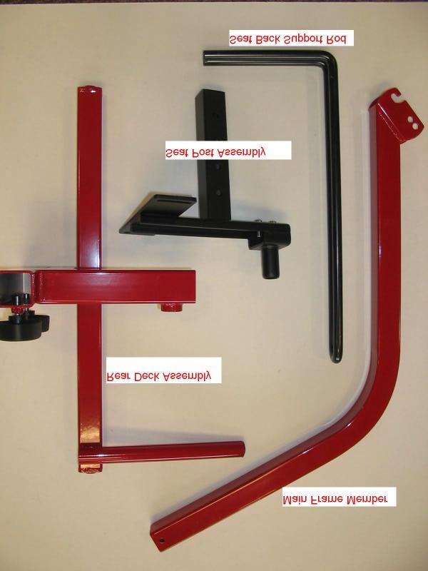
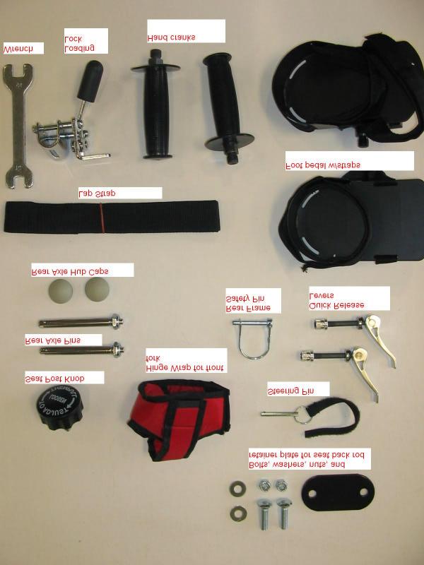
1 Amtryke Model AM-12 & AM-16 Carton Contents Carefully remove and lay out all parts from the carton so as not to scratch or lose any parts or pieces. The shipping carton should contain the pictured items on the parts page (Pages 9-11) Remove all packaging material and discard. The carton will contain: 2- part boxes 1- seat back support rod 2- rear wheels 1- contoured saddle seat 1- front wheel assembly 1- rear deck assembly 1- main frame tube 1- seat post assembly 1- plastic seat back with chest straps Assembly Instructions 1. Attach Front Wheel Assembly to Main Frame Tube. Use the two quick release levers to attach main frame tube to the front wheel assembly. Install quick release lever in top hole in front wheel assembly. Insert it from the right side as shown in Figure 1. Figure 1. Page 1

 hole positions. Note: Chain guard goes on the rider s right site.")
2 2. Attach frame onto lever by dropping the slots in main frame tube over the quick release lever. Tighten with nut. Note: Install quick release levers on right side so that the levers will be inside the chain guard when tightened. See Figure 2. Figure Install second quick release lever into lower holes. See Figure 3. Note: there are three positions for the front fork angle. You can choose the correct angle of the front fork for your rider by moving the lower quick release lever into one of the three (3) hole positions. Note: Chain guard goes on the rider s right site. Fasten snugly before proceeding. Figure 3. CAUTION: Quick release levers must be fully tightened before riding! Tighten nut until snug, then push lever down until flat against frame. Make sure it s tight and does not wobble. Page 2


3 4. Place Rear Deck Assembly onto main Frame Tube. Slide the rear deck assembly onto main frame tube past the holes at rear of mainframe tube. First loosen the black frame knobs. Note: Black plastic knobs are on bottom tube of rear deck. The knobs are on the right side of the tryke. See Figure 4. Tighten the frame knobs just enough so frame does not slip. You will adjust length of frame later to fit your rider. Figure 4. CAUTION: Frame knobs must be fully tightened before riding! 5. Install Rear Wheels. Push pin in on rear of axle pin and insert into rear wheel. Note: axle pin inserts into indented side of wheel hub air valve is on opposite side. Note: Air inflation valve faces the inside of the tryke. Install rear wheels into holes for axles on rear deck assembly. Install gray rubber hub caps over axel pins once wheels are installed on frame. See Figure 5. Figure 5. CAUTION: Make sure rear wheel axles are fully inserted and locked before riding! Page 3


4 6. Install Safety Pin. WARNING: Do NOT operate AmTryke without a safety pin. Safety pin must always be in place to prevent accidental separation of the rear deck from the main tube. See Figure 6 7. Figure 6. Figure Install Loading lock. Slide loading lock on the loading lock rod on the rear frame assembly. Top of loading lock should be flush with the top of tube. Take care that the lever is not touching the tire. The handle is in line with the tire and points towards the front of the tryke. Tighten with 10mm wrench. See Figure 8. CAUTION: Loading lock is not for braking during riding! Loading lock is only for use in transferring rider onto stationary tryke. Page 4 Figure 8.


 Slide seat back rod onto bracket. (Figure 11.")
5 8. Install Seat Post and Seat Back Support Rod.. a. Screw seat post knob into hole in rear deck assembly just until the spring-loaded indent pin is visible inside the tube. Pull on spring-loaded knob and drop in seat post assembly. Choose one of four seat height positions. The indent pin will snap into place. Tighten the knob. See Figure 9. CAUTION: Seat post knob must be properly placed into hole in seat post and tightened before riding! Figure 9. b. Install 9 1/16-inch bolt from bottom of bracket into square hole pointing up. (Figure 10.) Slide seat back rod onto bracket. (Figure 11.) Place the black retainer plate onto the bolt and add washer and nut. (Figure 12.) Tighten with 14 mm wrench provided or 9 1/16-inch wrench. (Figure 13.) Repeat with second bolt. Be sure to not over tighten. Final adjustments will be made when the rider is on the bike. See Figures Figure 10. Figure 11. Figure 12. Figure 13. Page 5


 and L (left) on the ends of the pedal axles.")
6 CAUTION: FINAL ADJUSTMENTS FOR RIDER S SIZE MUST BE COMPLETED FOR SEAT AND SEAT BACK ASSEMBLY AND FULLY TIGHTENED BEFORE RIDING OR INJURY COULD RESULT! 9. Install Contoured Saddle Seat. Install saddle seat onto seat post on seat post assembly. Be sure seat is fully seated onto post. Align with front of tryke and tilt to preferred position. Tighten seat clamp equally on both sides with 9/16 inch wrench. 10. Install Lap Strap. Thread the lap strap through slots in bracket at back of seat post assembly. 11. Install Plastic Seat Back. The plastic seat back is installed onto the seat back support rod. First, remove knobs, washers, and straps from plastic seat back. The slot in the bottom of the seat back fits over the support rod. The screw fits through the seat back and the slot between the rods. Add the larger fender washer and tighten with the t- shaped knob. Note: Black straps install through back of seat back. Choose whichever slots will best fit your rider. See Figures Figure 14. Figure Install Pedals. Pedals are labeled R (right) and L (left) on the ends of the pedal axles. The right pedal installs on the chain guard side of the tryke. Note: the right side threads clockwise to tighten. The left threads counter clockwise to tighten. DO NOT FORCE! Hand thread until you are certain threads are installed properly. See Figure 16. EASY TIP: Pedal threads tighten towards front of bike no matter which side you are on! Use 15mm wrench to tighten. Page 6 Figure 16.


7 13. Install Hand Cranks. Hand cranks are marked right and left as well and install the same way as pedals. Remember; the chain guard is on the rider s right side. See Figure 17. CAUTION: Be sure pedals and hand cranks are securely tightened before riding! Figure Install Steering Pin. If needed, install the steering pin with loop strap into hole in front of fork. The loop strap attaches to hook strap on inside of chain guard so the part will not be misplaced. The top hole locks the steering straight ahead. The lower hole allows approximately 20-degrees steering in either direction. You may find it desirable to limit steering so the rider can concentrate on learning the pedal motion at first. Jiggle Figure 18. the front wheel assembly as you push the pin into the hole and through the other side of the fork tube. Pin should insert all the way to the split ring to be correctly seated. See Figure 18. Page 7


8 15. Install Hinge Wrap. The hinge wrap is a safety pad to protect the rider s knees from hitting the hinges. It must be installed as shown before riding the AmTryke. See Figures Figure 19. Figure 20. Fitting the AmTryke tricycle to your Child Note: You may need assistance while fitting the tryke to your child. 1. Engage the loading lock. 2. For saddle seat option. Place child in saddle seat. Slide seat back assembly forward or back to suit your child s needs. Tighten bolts on underside of seat assembly. Adjust seat back up or down for the best support of your child s trunk. Tighten seat back knobs. 3. To adjust seat height, start with seat post in lowest position and adjust upward from there. 4. With feet in pedals slide rear deck assembly along horizontal frame to the length that when leg is extended the knee is slightly bent. Be careful not to extend frame so far that the knee locks when extended. 5. Tighten knobs until frame is snug (no wobbling). 6. If your child is having trouble keeping their feet on the self-righting pedals, use the two 19- inch black hook and loop straps (# ) and the enclosed directions to make a heel straps for the pedals. Register your AmTryke! It is very important that you please take a moment to fill out and submit the enclosed AmTryke registration form. This will help AmTryke, LLC keep track of what model of tryke you have should you need accessories or replacement parts in the future! Page 8

9 Parts for the AmTryke Model AM-12 & AM-16 Page 9
10 Page 10
11 Page 11
Amtryke Model Snappy #
 Amtryke Model Snappy #50-0150 Carton Contents Carefully remove and lay out all parts from the carton so as not to scratch or lose any parts or pieces. The shipping carton should contain the pictured items
Amtryke Model AM-12 #50-HFC-0210 Amtryke Model AM-16 #50-HFC-0411 Note: Shown with Saddle Seat and Curved Plastic Seat Back
 Amtryke Model AM-12 #50-HFC-0210 Amtryke Model AM-16 #50-HFC-0411 Note: Shown with Saddle Seat and Curved Plastic Seat Back Carton Contents Carefully remove and lay out all parts from the carton so as
AmTryke Adult Recumbent Model JT2000 #50-FC-2000
 AmTryke Adult Recumbent Model JT2000 #50-FC-2000 TOOLS Needed for Assembly 5 mm Allen Wrench 8 mm Socket or Wrench 10 mm Socket or Wrench 14 mm Socket or Wrench 15 mm Socket or Wrench 22 mm Socket or Adjustable
AmTryke Adult Recumbent Model HP1000 #50-HC-1000
 AmTryke Adult Recumbent Model HP1000 #50-HC-1000 TOOLS Needed for Assembly 5 mm Allen Wrench 8 mm Socket or Wrench 10 mm Socket or Wrench 14 mm Socket or Wrench 15 mm Socket or Wrench 22 mm Socket or Adjustable
Final Assembly Instructions Portside Cruiser
 Final Assembly Instructions Portside Cruiser Thank you for buying your new bicycle from L.L.Bean. Read these instructions carefully before beginning the final assembly. Prior to shipping, our expert cycling
Runabout Model 13-SC250/SC350 Trailer Owner s Manual
 Runabout Model 13-SC250/SC350 Trailer Owner s Manual Please keep this Owner s Manual for future reference. If you sell or give this product away, please include this Owner s Manual, and ask the new owner
Single Seat Trailer. Owner s manual and safety instructions
 Single Seat Trailer Owner s manual and safety instructions Owner s Manual Every effort has been made to ensure your trailer is of top quality and proven safe design, ready to provide you with many years
Final Assembly Instructions Casco Bay Cruiser
 Final Assembly Instructions Casco Bay Cruiser Thank you for buying your new bicycle from L.L.Bean. Read these instructions carefully before beginning the final assembly. Prior to shipping, our expert cycling
Large Tricycle (Wrangler) R140 Product Manual
 R140 Product Manual") Large Tricycle (Wrangler) R140 Product Manual Contents Warnings and Important Information 3 Recommended Use 4 User and Item Dimensions 4 Checking Your Order 4 The Frame 5 The Handlebar and Handbrake 6
Large Tricycle (Wrangler) R140 Product Manual Contents Warnings and Important Information 3 Recommended Use 4 User and Item Dimensions 4 Checking Your Order 4 The Frame 5 The Handlebar and Handbrake 6
Pet Bicycle Trailer/Jogger. Owner s Manual & Instructions
 Pet Bicycle Trailer/Jogger Owner s Manual & Instructions Congratulations on your purchase of the Pet Bicycle Trailer/Jogger. Please read through this manual and following the instructions before and during
Final Assembly Instructions: Bikes with Threadless Headsets
 Final Assembly Instructions: Bikes with Threadless Headsets Thank you for buying your new bicycle from L.L.Bean. Read these instructions carefully before beginning the final assembly. Prior to shipping,
rungu juggernaut owners manual
 rungu juggernaut owners manual Congratulations on purchasing the Juggernaut 1! Before you ride and make new tracks, please read the following instructions carefully. IMPORTANT- Standard Bearer Machines
Final Assembly Instructions: Runaround Cruiser
 Final Assembly Instructions: Runaround Cruiser Thank you for buying your new bicycle from L.L.Bean. Read these instructions carefully before beginning the final assembly. Prior to shipping, our expert
Owner s Manual for 16 Slider
 Owner s Manual for 16 Slider This manual contains important safety, assembly, operation and maintenance information. Please read and fully understand this manual before operation. Save this manual for
MODEL SST1 JOGGER/BIKE TRAILER. Owner s Manual should be kept for future reference
 PRODUCT REGISTRATION: MAKE SURE TO REGISTER YOUR PURCHASE AT http://allensportsusa.com/about/product-registration TO QUALIFY FOR PRODUCT WARRANTY AND TO RECEIVE IMPORTANT PRODUCT NOTIFICATIONS 1 MODEL
Assembly Instructions
 1/12 BEAST MANUAL Table of Contents Bike Specs - pg. 3 Bike Assembly: Assembling the Wheels- pg. 4 Assembling the Stem- pg. 5 Assembling the Handlebar- pg.6 Attaching the Seat- pg. 6 Attaching the Pedals-
Build an electric Scoot-car
 513 Build an electric Scoot-car Designed by ROBERT W O O L S O N Here's a sidewalk special for young hot rodders that safely takes the corner on two wheels, has two forward speed and brakes that stop on
Installation Guide Current Ford F-250 & Ford F-350 Super Duty. Product Code: 109 & 119
 Installation Guide 2008 - Current Ford F-250 & Ford F-350 Super Duty Product Code: 109 & 119 September 1, 2012 Tools Needed Components Included 3/8" Drill P2 Tip #2 Philips Screwdriver 1/2" Drill Bit Hinged
CHAINGUARD REGAL ST COLOR
 DESOTO/ REGAL HAULER PARTS LIST Item Part # Description QTY Item Part # Description QTY 1 11871 REFLECTOR KIT TRIKE 1 32 11764 FENDER BRACE 24" MWT 1 2 12199 SCREW #14 x 3/4 4 33 12176 NUT5/16-24 HEX 2
This is the Unpacking Guide for the Optibike Pioneer Allroad electric bicycle. The Guide provides information required to remove the Allroad from the
 This is the Unpacking Guide for the Optibike Pioneer Allroad electric bicycle. The Guide provides information required to remove the Allroad from the box and assemble it. If you have not assembled a bicycle
CHAINGUARD REGAL ST COLOR
 DESOTO/ REGAL HAULER PARTS LIST Item Part # Description QTY Item Part # Description QTY 1 11871 REFLECTOR KIT TRIKE 1 32 11762 FENDER BRACE 20" MWT 1 2 12199 SCREW #14 x 3/4 4 11764 FENDER BRACE 24" MWT
ELECTRIC BICYCLE OWNER S MANUAL.
 ELECTRIC BICYCLE OWNER S MANUAL www.gowattson.com Hello. 1 Assembly. 2 Overview. 2 Step One: Removing the Front Basket. 3 Step Two: Mounting the Handlebars & Display. 4 Step Three: Replacing the Front
Fasteners. Consumer Information WARNING
 73528 Please keep this instruction sheet for future reference, as it contains important information. Adult assembly is required. Age: 1½ years - 5 years. Weight Limit: 50 lbs. (23 kg). Tools needed for
Generation II Installation Guide
 Generation II Installation Guide HayDay, LLC 9323 N. Government Way Unit 402 Hayden, Idaho 1-800-732-1654 www.stablegrazer.com Congratulations on your purchase of the Stable Grazer Generation II automatic
Comfort Tri-Rider Assembly Guide
 1. Carefully remove all the components and packaged hardware from the shipping boxes. 2. Remove all protective materials from the fork, front frame and rear frame sections. 3. Read this assembly manual
CALIFORNIA TRIMMER MOWER MAINTENANCE MANUAL
 CALIFORNIA TRIMMER MOWER MAINTENANCE MANUAL 2 Table of Contents Section 1: General Information Page Handle Assembly Instructions 4 Maintenance All Models 6 Oil Change Procedures All Models 9 Height Adjustment
Wheel Horse. 36 Tiller. Model No & Up. Operator s Manual
 FORM NO. 8 9 Rev. A Wheel Horse 6 Tiller for Classic Garden Tractors Model No. 7970 690000 & Up Operator s Manual IMPORTANT: Read this manual carefully. It contains information about your safety and the
ASSEMBLY INSTRUCTIONS / OWNERS MANUAL AIR BIKE AB-1
 AIR BIKE AB- ASSEMBLY INSTRUCTIONS / OWNERS MANUAL IMPORTANT : READ ALL ASSEMBLY INSTRUCTIONS AND SAFETY PRECAUTIONS BEFORE USING THIS PRODUCT. REFERENCE ALL SAFETY GUIDELINES AND WARNING LABELS. RETAIN
User Manual of Bagibike Electric Bicycles
 User Manual of Bagibike Electric Bicycles Model: Bagibike B16. http://www.bagibike.com Page 1 FOREWORD The following operation manual is a guide to assist you. This manual is not a complete document on
Quick N EZ. Two Seat Bicycle Trailer with Stroller Attachment
 Quick N EZ Two Seat Bicycle Trailer with Stroller Attachment User s Manual This manual contains safety, assembly, use and maintenance instructions. Read these instructions carefully before use and keep
Procedure Replacing a Cover
 Procedure 7.1 - Replacing a Cover Cover Removal 1. Remove two screws, one each side, from the front of the top cover. Remove the top cover. See Diagram 7.1. Diagram 7.1 - RBK 815 Covers Top Cover Left
DC Series Installation Manual (# )
") DC Series Installation Manual (# 101630) Page 1 of 33 In this booklet you will find: TOWER INSTALLATION... 3 U-Bolt Style mount... 4 Side Frame Style mount... 4 PIVOT INSTALLATION... 5 External Pivot Installation:
DC Series Installation Manual (# 101630) Page 1 of 33 In this booklet you will find: TOWER INSTALLATION... 3 U-Bolt Style mount... 4 Side Frame Style mount... 4 PIVOT INSTALLATION... 5 External Pivot Installation:
WARNING: the engine does not come with oil in it. Please fill the oil before starting. The 200cc hardknock requires 9/10 of a quart of oil.
 WARNING: the engine does not come with oil in it. Please fill the oil before starting. The 200cc hardknock requires 9/10 of a quart of oil. Things needed for assembly. -2 tubes of blue loc-tite. I don
MODEL XLT-X2 BIKE TRAILER. Owner s Manual should be kept for future reference
 1 MODEL XLT-X2 BIKE TRAILER Owner s Manual should be kept for future reference 1. Completely read and understand Owner s Manual before assembling or operating this product. 2. This product should be assembled
M
 M5727 Please keep this instruction sheet for future reference, as it contains important information. Adult assembly is required. Tools required for assembly: Phillips Screwdriver, Hammer and Scrap Block
Logo/Company Name 4 w x.75 h. Assembly Instructions. 1) Remove base, back/back bar, pneumatic cylinder, casters/glides, and seat from box.
 Remove base, back/back bar, pneumatic cylinder, casters/glides, and seat from box.") w x. h ) Remove base, back/back bar, pneumatic cylinder, casters/glides, and seat from box. ) Put casters or glides on base. Use pressure to push in (). ) Slide optional foot ring () over pneumatic cylinder
w x. h ) Remove base, back/back bar, pneumatic cylinder, casters/glides, and seat from box. ) Put casters or glides on base. Use pressure to push in (). ) Slide optional foot ring () over pneumatic cylinder
Assembly Instructions
 www.rockymounts.com TandemMount R4 Installation Manual Guidelines/Restrictions: - This carrier is intended for Thule rectangular and Yakima round bars only. - Bicycles must be equipped with quick release
OPERATOR S MANUAL 2200 SERIES LIFT - LIL HOISTER. July 2017
 July 2017 OPERATOR S MANUAL 2200 SERIES LIFT - LIL HOISTER! Before operating this lift, read and understand this Operator s Manual. Become familiar with the potential hazards of this unit. Call SUMNER
THIS PRODUCT IS FOR PROFESSIONAL LABORATORY USE ONLY USER'S MANUAL. WELLS ENGINE UNIT 230 VOLT Product No. U905, U906, U907, U908
 DENTAL, INC. TECHNICAL BULLETIN U807-022510 5860 FLYNN CREEK ROAD READ ALL INSTRUCTIONS P.O. BOX 106 BEFORE PROCEEDING COMPTCHE, CALIFORNIA, U.S.A. 95427 SAVE THIS FOR FUTURE REFERENCE THIS PRODUCT IS
Owner s Manual Wren Inverted Suspension Forks
 Owner s Manual Wren Inverted Suspension Forks with Keyed Stanchions TwinAir System Carbon Bash Guards 2 - Travel/AC Clips 2 - Hose/Cable Guides 43mm Uppers 36mm Stanchions Check out our service videos
INSTALLATION GUIDE DODGE PRODUCT CODE:
 INSTALLATION GUIDE 2002-09 DODGE 1500-3500 PRODUCT CODE: 445 & 455 May 17, 2011 TOOLS NEEDED COMPONENTS INCLUDED 3/8" Drill P2 Tip 1/2" Drill Bit #2 Philips Screwdriver Flange(s) x 2 Hinged Lid Track(s)
Wren Inverted Suspension Forks with Keyed Stanchions and TwinAir System
 Owner s Manual Wren Inverted Suspension Forks with Keyed Stanchions and TwinAir System Congratulations You have just purchased a Wren Inverted Suspension Fork. The culmination of years of design, testing
ATTENTION: Please read this instruction before mounting and using. Disregarding the directions in this manual can cause damage or injury.
 Dual Function Trailer Manual ATTENTION: Please read this instruction before mounting and using. Disregarding the directions in this manual can cause damage or injury. 1 Model no. BT-1228SDU-S Before you
SHERPA 2.0 RACK PACKAGING IS AN ASSEMBLY FIXTURE. READ UNBOXING INSTRUCTIONS TO EASE ASSEMBLY.
 SHERPA 2.0 RACK PACKAGING IS AN ASSEMBLY FIXTURE. READ UNBOXING INSTRUCTIONS TO EASE ASSEMBLY. Parts: Rear Tray Mount Inner Tray Assembly Pivot Handle Lock Cable Outer Tray Assembly Pivot Assembly Front
INSTALLATION GUIDE STANDARD PRODUCT CODES:
 INSTALLATION GUIDE STANDARD PRODUCT CODES: 100, 105, 110, 111, 112, 113, 115, 120, 130, 140, 145, 146, 150, 200, 210, 240, 250, 255, 260, 300, 305, 405, 406, 407, 408, 425, 426, 435, 447, 500, 505, 510,
STEPMILL 7000 PT ASSEMBLY INSTRUCTIONS PART NUMBER 27698
 STEPMILL 7000 PT ASSEMBLY INSTRUCTIONS PART NUMBER 27698 1 TOOLS REQUIRED: KNIFE 2-9/16 WRENCHES 5/32 ALLEN WRENCH 1. USE KNIFE TO CUT AND REMOVE PLASTIC STRAPS. TOP COVER PLASTIC STRAPS 2. REMOVE TOP
SUNNY PRO INDOOR CYCLING BIKE
 SUNNY PRO INDOOR CYCLING BIKE SF-B901 USER MANUAL IMPORTANT! Please retain owner s manual for maintenance and adjustment instructions. Your satisfaction is very important to us, PLEASE DO NOT RETURN UNTIL
Recumbent Hitch Rack Instruction Manual
 Recumbent Hitch Rack Instruction Manual Model 45816 2 receiver Model 45815 1 ¼ receiver Not to be used on any trailer, fifth wheel or vehicle being towed by another vehicle Weight Limit 125lbs/57 kg The
PRO INDOOR CYCLING BIKE
 PRO INDOOR CYCLING BIKE SF-B901 USER MANUAL IMPORTANT! Please retain owner s manual for maintenance and adjustment instructions. Your satisfaction is very important to us, PLEASE DO NOT RETURN UNTIL YOU
2 IN 1 TRAILER/STROLLER - PTDD
 I N S T R U C T I O N S D A T E : 1 9-1 - 2 0 1 7 2 IN 1 TRAILER/STROLLER - PTDD COMPONENTI - TRAILER COMPONENTS 1. all weather cover 2. tow bar and hitch connector 3. tow bar receiver 4. removable handlebar
Air Mod-Kit Changing out the 7 poly wheels on the rear of the T78 to 8.5 rubber air tires TRIKKE
 Air Mod-Kit Changing out the 7 poly wheels on the rear of the T78 to 8.5 rubber air tires. T78-CS Air Mod-Kit Disclaimer This document was written by Trikke Tampa. It s of our own opinion and example of
Logo/Company Name 4 w x.75 h. Assembly Instructions. 1) Remove base, back/back bar, pneumatic cylinder, casters/glides, and seat from box.
 Remove base, back/back bar, pneumatic cylinder, casters/glides, and seat from box.") 8 ) Remove base, back/back bar, pneumatic cylinder, casters/glides, and seat from box. ) Put casters or glides on base. Use pressure to push in (8). ) Slide optional foot ring () over pneumatic cylinder
8 ) Remove base, back/back bar, pneumatic cylinder, casters/glides, and seat from box. ) Put casters or glides on base. Use pressure to push in (8). ) Slide optional foot ring () over pneumatic cylinder
Bike Trailer Stroller Kit Accessory
 Bike Trailer Stroller Kit Accessory Owner s Manual Please keep this Owner s Manual for future reference. PRIOR TO ASSEMBLY Please read this Owner s Manual completely before assembling or operating this
B4A Instruction Manual
 Page 1 TABLE OF CONTENTS Vehicle Preparation 2 Floor Slope Calibration 2 Headlamp Aiming 4 Assembly Instructions / Large and Small Universal Adaptors 6 Aiming Instructions 8 Quick Headlamp Aim Check 15
Agri-Fab OWNER'S MANUAL. Model No POINT HITCH TRAILER.
 Agri-Fab OWNER'S MANUAL Model No. 45-0353 3-POINT HITCH TRAILER CAUTION: Read Rules for Safe Operation and Instructions Carefully Safety Assembly Operation Maintenance Parts the fastest way to purchase
Sherco Motorcycle Assembly Instructions
 Sherco Motorcycle Assembly This manual is intended to be used as an assembly guide for the Sherco 1.25 2.9 Trials Motorcycles. The motorcycle shown in the pictures is a new 2002, 2.9, the one that you
One- Touch Installation Instructions
 One- Touch Installation Instructions 1 1 Height Adjustable Pivot w/ screws 9 Upper Work Surface 2 Rail Mount Knobs 10 Back Cover 3 Transformer 11 Center Pivot w/ screws 4 Support Legs 12 Left Monitor Arm
child trailer Burley Bee and Honey Bee Owner s Instruction and Safety Manual Designed For One Or Two Children Burley Bee model shown Honey Bee
 child trailer Burley Bee and Honey Bee Owner s Instruction and Safety Manual Designed For One Or Two Children Honey Bee Burley Bee model shown child trailer Burley Bee and Honey Bee Owner s Instruction
202 Schwinn Recumbent Exercise Bike
 202 Schwinn Recumbent Exercise Bike Parts List Full Size Hardware Chart Product Illustration Assembly Instructions 202 Recumbent Exercise Bike IMPORTANT PRECAUTIONS WARNING: To reduce the risk of serious
GIO Electric Scooter Assembly Instructions. GIO Electric Scooter Assembly Instructions. 06 Italia 500w Electric Scooter Assembly Manual.
 GIO Electric Scooter Assembly Instructions GIO Electric Scooter Assembly Instructions 06 Italia 500w Electric Scooter Assembly Manual.indd 1 2/7/2014 11:24:55 PM 06 Italia 500w Electric Scooter Assembly
*CROSSBAR SPREAD Your crossbar spread is the distance between the crossbars. This hidden switch enables safe mounting outside the towers.
 VIPER (1x) Type of Rack Load Crossbar Spread* Limits WHEELSTRAP (1x) carriage bolt (1x) snap around (1x) Round Bar & Square Bar 1 or 2 bikes 3 or more bikes 16" - 42" 41cm - 107cm 18" - 42" 46cm - 107cm
Power Break II Circuit Breaker Accessories Motor Operator Mechanism
 g GEH 6281E Power Break II Circuit Breaker Accessories Motor Operator Mechanism Introduction The Motor Operator Mechanism, shown in Figure 1, can be installed in 800 4000 A frame Power Break II circuit
ASSEMBLY INSTRUCTIONS & OWNER S MANUAL
 Caution: For Safety Read and Follow Assembly and Operating Instructions Carefully ASSEMBLY INSTRUCTIONS & OWNER S MANUAL McCONKEY INC. P.O. Box 1362 Seeley Lake, MT 59868 1 of 7 NEED HELP? Please visit
Grass Catcher. Instructional / Parts Manual Part Number: January ( & ) & Drive Kits ( , , )
 & Drive Kits ( , , )") Grass Catcher Instructional / Parts Manual Part Number: January 200 5020 ( 507 & 5026 ) & Drive Kits ( 52030, 5203, 52032) Table of Contents Z RIDER GRASS CATCHER TWO PACKAGED ITEMS LIST 507 BLOWER ASSEMBLY
Grass Catcher Instructional / Parts Manual Part Number: January 200 5020 ( 507 & 5026 ) & Drive Kits ( 52030, 5203, 52032) Table of Contents Z RIDER GRASS CATCHER TWO PACKAGED ITEMS LIST 507 BLOWER ASSEMBLY
INSTRUCTION MANUAL
 WWW.BIGCATUSA.COM 631 285 2298 INSTRUCTION MANUAL Congratulations On Your Purchase & Thank You For Choosing Big Cat Warning: This manual is only a guide to assist you. This Guide is not a complete or comprehensive
Table of Contents. Technical Information Warning Statement
 Table of Contents Technical Information-----------------------------------1 Warning Statement--------------------------------------2 Read Before Riding-------------------------------------3 List of Parts-----------------------------------------------4
Owner s Instruction and Safety Manual. child trailer. Burley Honey Bee
 Owner s Instruction and Safety Manual child trailer Burley Honey Bee Stroll Bike Contents Owner s Instruction and Safety Manual Burley Honey Bee 3 Introduction 3 Safety Guidelines 3 Parts Bag Contents
BRISTER S UTV ASSEMBLY INSTRUCTIONS
 BRISTER S UTV ASSEMBLY INSTRUCTIONS 1 Uncrating and Assembly Instructions Utility Vehicle Uncrating and Assembly Instructions Your new Brister s Utility vehicle should include the following items to be
child trailer Burley d lite, Encore, Solo and LE Tiger d lite Owner s Instruction and Safety Manual Designed For One Or Two Children (Optional)
") Burley d lite, Encore, Solo and LE Tiger d lite Owner s Instruction and Safety Manual child trailer Designed For One Or Two Children (Optional) (Optional) (Optional) child trailer Burley d lite, Encore,
Burley d lite, Encore, Solo and LE Tiger d lite Owner s Instruction and Safety Manual child trailer Designed For One Or Two Children (Optional) (Optional) (Optional) child trailer Burley d lite, Encore,
*NOTE* The following suspension system will not work with heavy duty axle housings as pictured below.
 1964 ½ - 1970 Ford Mustang Triangulated 4-Link Suspension Installation Instructions Tech Line: 1-855-693-1259 www.totalcostinvolved.com Read and understand these instructions before starting any work!
Installation Guide Currie Electro-Drive Conversion Kits 2, 3, & 4
 Installation Guide Currie Electro-Drive Conversion Kits 2, 3, & 4 1 Before you start... Use this information to determine whether one of our kits will fit your bike Drawing Ref. Fork Area Leg clearance
<THESE INSTRUCTIONS MUST BE GIVEN TO THE END USER> B&W
 B&W Trailer Hitches 6 Hawaii Rd / PO Box 86 Humboldt, KS 66748 P:60.473664 F:60.869.903 Turnoverball Gooseneck Hitch Installation Instructions MODEL 08
BELT DRIVE PRO INDOOR CYCLING BIKE SF-B901B USER MANUAL
 BELT DRIVE PRO INDOOR CYCLING BIKE SF-B901B USER MANUAL IMPORTANT! Please retain owner s manual for maintenance and adjustment instructions. Your satisfaction is very important to us, PLEASE DO NOT RETURN
Installation Instructions. QuickSilver Shifter. Fits: GM, Ford, Chrysler Transmissions See Application Guide for Specific Applications Part # 80683
 Installation Instructions QuickSilver Shifter Fits: GM, Ford, Chrysler Transmissions See Application Guide for Specific Applications Part # 80683 WORK SAFELY! For maximum safety, perform this installation
Owner s Manual. This manual contains important safety, assembly, operation and maintenance information.
 Owner s Manual This manual contains important safety, assembly, operation and maintenance information. Please read and fully understand this manual before operation. Save this manual for future reference.
Owner s Manual Read and keep this manual. Patents World Wide
 Owner s Manual Read and keep this manual. Patents World Wide S & S Industries, Inc., Sarasota, FL, USA www.trail-gator.com Copyright 2006 All Rights Reserved The following manual is provided to assist
How to install shifter style lever (Gen 1 & Gen
 How to install shifter style lever (Gen 1 & Gen 2) Written By: The Hive 2017 service.bythehive.com Page 1 of 10 TOOLS: T25 Torx wrench (1) Cable cutter (1) M3 Hex wrench (1) 2017 service.bythehive.com
Schwinn IC Bikes. Assembly Manual. Evolution, Evolution SR. Nautilus Bowflex Schwinn Fitness Pearl Izumi StairMaster Universal Nautilus Institute
 Schwinn IC Bikes Evolution, Evolution SR Nautilus Bowflex Schwinn Fitness Pearl Izumi StairMaster Universal Nautilus Institute PN001-7189 (12/11/2007) Table of Contents Product Specifications 2 Safety
ENCORE 52" X-TREME. 2-BAG GRASS CATCHER for units w/ S/N and above ASSEMBLY AND PARTS DIAGRAMS
 ENCORE 52" X-TREME 2-BAG GRASS CATCHER for units w/ S/N 53138 and above ASSEMBLY AND PARTS DIAGRAMS Notes: ASSEMBLY INSTRUCTION Figure 1 Using 1/2" wrench, remove the discharge cover and the RH deck belt
Hollywood Racks Assembly & installation instructions for models:
 Hollywood Racks Assembly & installation instructions for models: HR1400Y (4 bike), HR1450Y (2 bike), HR1475Y, 1450Y-E & 1455Y-E (E bikes) For use on 2 hitches only. Do not use a 1 ¼ -2 hitch adapter. Maximum
Start-up and Operation
 Start-up and Operation NEVER FORGET THAT ANY MACHINE CAN BE VERY DANGEROUS WHEN NOT OPERATED CORRECTLY AND SAFELY. ALWAYS VISUALLY CHECK TO MAKE SURE THAT ALL PERSONS ARE CLEAR BEFORE TURNING ON ANY CONTROLS.
1. Single-speed bicycle (SSB) lower fork legs... Page 3 2. Multi-speed bicycle (MSB) lower fork legs... Page 4
 lower fork legs... Page 3 2. Multi-speed bicycle (MSB) lower fork legs... Page 4") TM owner s instruction manual the ULTIMATE SURFBOARD RACK I. Messages & Warnings...Page 2 II. FORK BASE UNIT COMPONENTS...Page 2 III. SELECTING PROPER LEG TYPE...Page 2 IV. LEG LENGTH ADJUSTMENT & FORK
TM owner s instruction manual the ULTIMATE SURFBOARD RACK I. Messages & Warnings...Page 2 II. FORK BASE UNIT COMPONENTS...Page 2 III. SELECTING PROPER LEG TYPE...Page 2 IV. LEG LENGTH ADJUSTMENT & FORK
Advancement Chair. R901, R902, & R903 Product Manual
 Advancement Chair R901, R902, & R903 Product Manual Contents Warnings and Important Information 3 Recommended Use 4 User and Item Dimensions 4 Assembly and Adjustment Information 5 Maintenance 14 Cleaning
RECARO ProSport Reha. Instructions for assembly and use of the Reha version (supplement) Internet Download:
 Internet Download:") RECARO ProSport Reha Instructions for assembly and use of the Reha version (supplement) Internet Download: www.thomashilfen.us Dear RECARO ProSport Reha user, To make handling of your new children car
RECARO ProSport Reha Instructions for assembly and use of the Reha version (supplement) Internet Download: www.thomashilfen.us Dear RECARO ProSport Reha user, To make handling of your new children car
Agri-Fab OWNERS MANUAL. Model No LB. PUSH BROADCAST SPREADER. Assembly Operation Maintenance Repair Parts
 Agri-Fab OWNERS MANUAL Model No. 45-02103-101 SHIELD UP - 8 TO 18 FT. SPREAD WIDTH SHIELD DOWN - 3 TO 4 FT. SPREAD WIDTH 125 LB. PUSH BROADCAST SPREADER CAUTION: Read Rules for Safe Operation and Instructions
Retrofit Steering Column Installation Instructions
 Retrofit Steering Column Installation Instructions for 1967 Mustangs www.ididitinc.com 610 S. Maumee St., Tecumseh, MI 49286 PH: (517) 424-0577 FAX: (517) 424-7293 Revised 9/29/2009 Instruction #: 8000000014
SECTION V ASSEMBLY CAUTION THE FOLLOWING SAFETY PRECAUTIONS SHOULD BE THOROUGHLY UNDERSTOOD BEFORE ATTEMPTING MACHINE ASSEMBLY.
 SECTION V ASSEMBLY CAUTION THE FOLLOWING SAFETY PRECAUTIONS SHOULD BE THOROUGHLY UNDERSTOOD BEFORE ATTEMPTING MACHINE ASSEMBLY. 1. Wear personal protective equipment such as, but not limited to protection
INSTALLATION INSTRUCTIONS FOR: DECK LIFT KIT 629GN-001A
 INSTALLATION INSTRUCTIONS FOR: DECK LIFT KIT 629GN-001A 1. SHUT OFF THE ENGINE AND SET THE PARK BRAKE. 2. ROTATE THE FRONT CASTER WHEELS AWAY FROM THE DECK. (SEE ILLUSTRATION 3) 3. REMOVE THE DECK HEIGHT
Single Seat Bicycle Trailer
 Single Seat Bicycle Trailer User s Manual This manual contains safety, assembly, use and maintenance instructions. Read these instructions carefully before use and keep them for future reference. Your
XChange Seat Service and Maintenance Guide
 XChange Seat Service and Maintenance Guide Table Of Contents Page General Information... 1 Registration Information... 1 Seat Cushion Latch... 2 Lap Shoulder Belt Replacement... 2 Sliding Buckles Replacement...
Peg-Harness installation instructions
 Peg-Harness installation instructions I know it s not the easiest thing to do, but PLEASE READ THESE INSTRUCTIONS COMPLETELY so you will understand what you are trying to accomplish before you start drilling
Child Restraint Owner s Manual READ THIS MANUAL. D265353C CAR SEAT
 CAR SEAT Child Restraint Owner s Manual READ THIS MANUAL. Do not install or use this child restraint until you read and understand the instructions in this manual. FAILURE TO PROPERLY USE THIS CHILD RESTRAINT
Performance Tech Support 1(800)
") 05_MillenniumFluidForce/INS.qk 7/19/05 1:5 PM Page 1 Performance Tech Support 1(800)553-834 Performance, Inc. One Performance Way Chapel Hill, N.C. 7514 1-800-77-453 Made in China www.performancebike.com
05_MillenniumFluidForce/INS.qk 7/19/05 1:5 PM Page 1 Performance Tech Support 1(800)553-834 Performance, Inc. One Performance Way Chapel Hill, N.C. 7514 1-800-77-453 Made in China www.performancebike.com
Installation Instructions Supertop NX Twill
 Installation Instructions Supertop NX Twill Vehicle Application: Jeep Wrangler Unlimited 2007-current Part Number 54823 Installation Tips Before you begin installing your new Supertop NX Twill, please
ProLine. 44 Mower. for 120 Traction Unit. Model No & Up. Operator s Manual
 FORM NO. 9 ProLine Mower for 0 Traction Unit Model No. 05 99000 & Up Operator s Manual IMPORTANT: Read this manual carefully. It contains information about your safety and the safety of others. Also become
Competitor. Ultra Light Plus, Semi Electric Bed. Item # 15560, HR Owner s Assembly And Operating Manual
 Competitor Ultra Light Plus, Semi Electric Bed Item # 15560, 15560-HR Owner s Assembly And Operating Manual Note: The competitor bed is available with half-rails (not shown). See page 16 for installation
MODEL AST202 BIKE TRAILER. Owner s Manual should be kept for future reference
 INSTRUCTIONAL PRODUCT REGISTRATION: MAKE SURE TO REGISTER YOUR PURCHASE AT http://allensportsusa.com/about/product-registration TO QUALIFY FOR PRODUCT WARRANTY AND TO RECEIVE IMPORTANT PRODUCT NOTIFICATIONS
OWNERS MANUAL. Model No LB. PUSH BROADCAST SPREADER. Assembly Operation Maintenance Repair Parts
 OWNERS MANUAL Model No. 45-02102-101 SHIELD UP - 8 TO 18 FT. SPREAD WIDTH SHIELD DOWN - 3 TO 4 FT. SPREAD WIDTH 125 LB. PUSH BROADCAST SPREADER CAUTION: Read Rules for Safe Operation and Instructions Carefully
Spirit Trailer with stroller attachment
 Spirit Trailer with stroller attachment User s Manual This manual contains safety, assembly, use and maintenance instructions. Read these instructions carefully before use and keep them for future reference.
Lumina TWO SEAT BICYCLE TRAILER WITH STROLLER ATTACHMENT
 Lumina TWO SEAT BICYCLE TRAILER WITH STROLLER ATTACHMENT Owner s Manual This manual contains safety, assembly, use and maintenance instructions. Read these instructions carefully before use and keep them