?--~~--~~~~~~~~~~~~~~~~~
|
|
|
- Nathan Reed
- 5 years ago
- Views:
Transcription
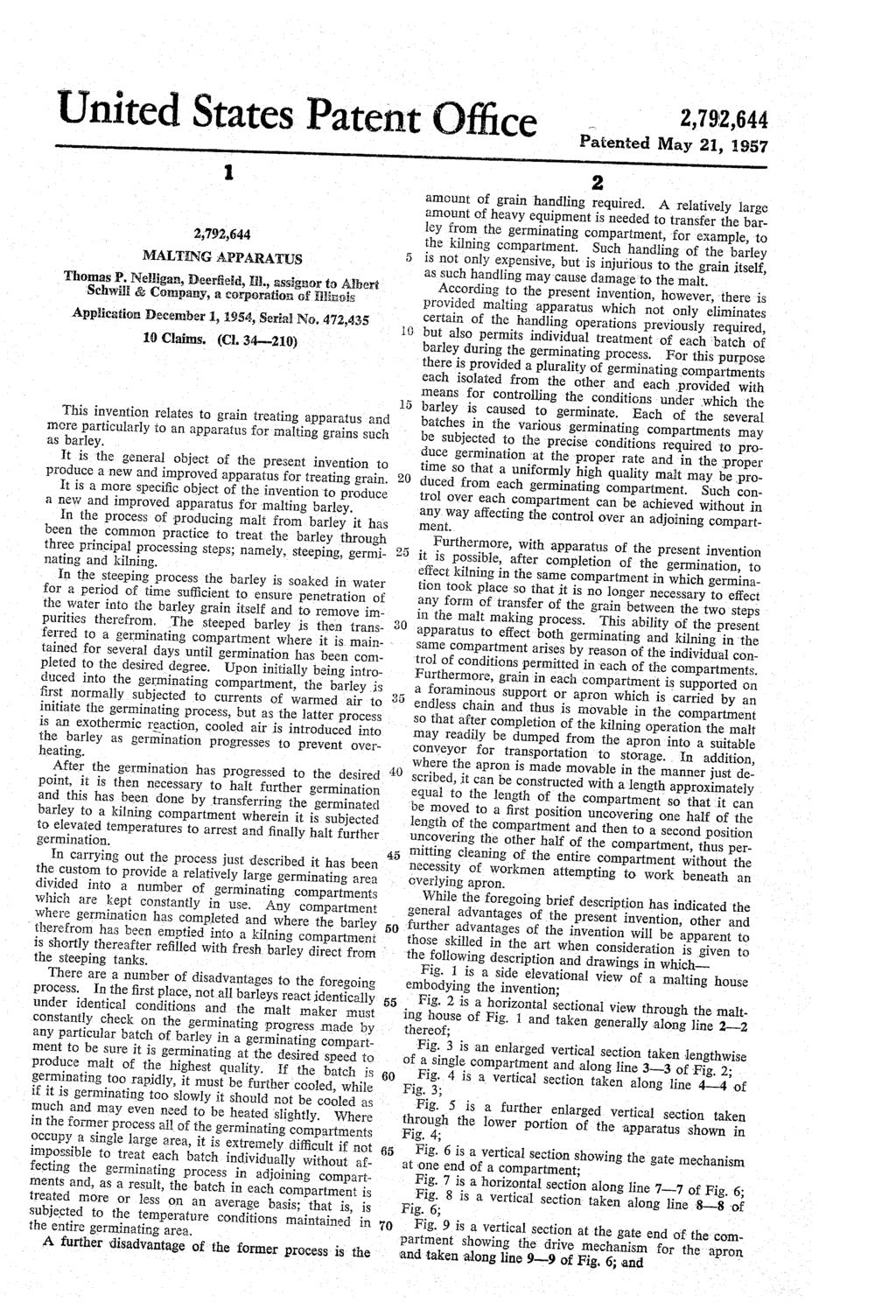
1 May 21, 1957 Filed Dec. 1, 1954 T. FP. ELLIGA MALTIG APPARATUS 2,792,644 6 Sheets-Sheet li S LLLLLLLLSL LLLLL LL LSLS LSLSLSLSLSqLqLqqLSLSLSLSLSLSLSLSLSqLqLqSqLSLLq Sqqqqq R AARMAKSMASKAKARAKKAR R VA? R S Sð WAYAAVAAMWAYAMAYA?--~~--~~~~~~~~~~~~~~~~~ Ya AAYAYA-YAVYA'YA YAYKAYA YAYA ~- = = r----~- : VAVAVAV A. AVYAVAVAVAV YA *?***********************?* ************************** LLS L LLLL LSL SLL LSS SSLLLLLSSLLLLS SLSLLLS S SLLLL LLLLLLLLSqSLLLSLL qq LLLLLLLS AYAAYAVAYMAYVYYAMA S. VAVRAAVAKAVKASVAVARAVAY 7702 IVE TOR. A/e/222av.???????????
2 May 21, 1957 T. P. ELLGA 2,792,644 MALTIG APPARATUS Filed Dec. 1, Sheets-Sheet
3
4
5 May 21, 1957 T. P. ELLIGA 2,792,644 MALTIG APPARATUS Filed Dec. 1, Sheets-Sheet 5 IVETOR a5 A/We/ZZ an
6 May 21, 1957 T. P. I ELLIGA 2,792,644 MALTIG APPARATUS Filed Dec, l, Sheets-Sheet ŽØ 77uQzmas APWeZZ?aze, IVETOR.
7

8 3 Fig. 10 is a schematic view of the carrier chain and movable apron showing the apron in several positions. While this invention is susceptible of embodiments in many different forms, there is shown in the drawings and will herein be described in detail one specific embodiment, with the understanding that the present disclosure is to be considered as an exemplification of the principles of the invention and is not intended to limit the invention to the embodiment illustrated. The scope of the inven tion will be pointed out in the appended claims. Referring now to Figs. 1 and 2, there is shown a malt ing house, generally designated 29, divided by suitable partitions into four compartments designated 2, 22, 23, and 24. A duct for introducing air into the compart ments is provided for each compartment and designated on Fig. 2 as 25, 26, 27, and 28, respectively. Each duct is provided with a plurality of openings indicated at 29 so that air under pressure introduced into a duct may flow into its respective compartment. Each of the open ings 29 is provided with means to control the flow of air therethrough, such means preferably taking the form of a sliding door. For introducing conditioned air into the ducts, there is provided at one end of the malting house 26 suitable air conditioning apparatus generally indicated as 39, such apparatus comprising a suitable heater 3 for heating air, a cooler 32 for cooling air, together with a pair of headers 33 and 34 connected to the heater and cooler respectively. For each duct there is provided a blower designated 35, 36, 37, and 38, respectively, each provided with suitable controllable connections to the headers 33 and 34, so that air at the right temperature and under the right con ditions may be introduced under pressure into each duct for flow into the proper compartment. Referring now to Figs. 3 and 4, it will be seen that each compartment is provided with a top wall 41), a bot tom wall 41 and side walls 42 and 43, the reference nu merals being applied to the compartment 23 and similar partitions are provided for each of the other compart ments. The bottom wall 41 is inclined inwardly towards its center where there is located a drain 44 for draining water from the compartment. It will be noted that the ducts previously mentioned are defined by concrete walls with each duct having a top, the upper side of which provides a catwalk 45 extending along the length of the compartment and guarded by a suitable guard rail 46. As previously noted, the openings 29 from the duct into the compartment are controllable through the medium of sliding doors 47. In each compartment there is provided a flexible fo raminous apron 50 extending horizontally from end to end of the compartment with the apron being reinforced by suitable underlying beams 51 extending crosswise thereof so as to enable the apron to carry a batch of barley thereon during the germinating and kilning proc esses. Each apron 50 has a length approximately equal to the length of the compartment and, when in the posi tion shown in the upper figure of Fig. 10, is in position to receive barley from the steep tanks. Preferably the barley is introduced into the compartment through a header 52 extending along the top wall of the compart ment for substantially its entire length and provided at intervals with controllable valves 53 which may be opened to permit the barley-water mixture from the steep tanks to flow therethrough onto the surface of the apron 50. ormally the grain is flowed onto the apron to a depth of about three or four feet, with Such depth being sub stantially uniform from end to end of the compartment. As will be noted from an examination of Fig. 5, the side wall 43 separates the compartment 23 from the duct 26, which duct is for the purpose of supplying condi tioned air to the adjoining compartment 22. To prevent transfer of heat from the compartment 23 to the adjoin ing duct 26, the side wall 43 is provided on either side with insulation ,792,644 4 The apron 5 is provided at intervals along its length with supporting rollers 56 interconnected by links 56a to form a pair of endless carrier chains, one extending along each side of the apron. The rollers 56 ride upon tracks 57 extending longitudinally along the entire length of the compartments and immediately above a second pair of tracks 58 having a similar extent. As will be noted from an inspection of Fig. 8, the apron 59 is made up of a 30 plurality of foraminous sections 62. The carrier chain is constructed to engage suitably conformed sprocket wheels 63 provided in pairs at each end of the compart ment and means later to be described are provided for rotating the sprocket wheels thereby to move the apron lengthwise of itself and to cause it to assume the various positions within the chamber illustrated in Fig. 10. Referring again to Fig. 5, it will be noted that the apron, when in the position of the uppernest illustration of Fig. 10, serves to divide the chamber into two sec tions, an upper section above the apron and a lower sec tion below the apron, and it will be further noted that the openings 29 associated with the compartment 23 are located so as to introduce air into the lower section of the compartment. It is desired that the air flow up wardly in the compartment passing through the foramin ous apron and filtering upwardly through the barley to maintain the conditions therein substantially uniform during the malting process. To prevent such air from passing around the side edges of the apron (and hence not through the grain carried thereby) sealing means are provided extending along the length of the com partment and serving to prevent such undesired air flow. For this purpose vertically positioned plates 62 and 63 are SS provided in each compartment and are mounted so as to have their lower edges closely adjacent the upper sur face of the apron. At their upper portions the sealing plates are sealed to abutments on the opposite side walls so as to provide a dead air space therebehind and thus effectively preventing flow upwardly in the compartment except through the apron. The plates 62 and 63, be ing preferably of stainless steel, are corrosion resistant and thus less liable to deterioration after periods of use, but also are capable of giving up any heat quite readily. In the kilning step of the process, the temperature in the compartment is raised to a relatively high level and held at such level until germination has been halted. Concrete walls have a tendency to retain such heat for a longer period and thus would delay the introduction of a new batch into the compartment until the was had cooled. The stainless steel plates 62 and 63, how ever, cool off quite rapidly and thus do not cause such delay. As the grain flows quite readily, means are provided for preventing leakage of the grain beneath thc lower edge of the sealing plates 62 and 63 and therefore each of the apron sections 60 is provided with a side wing 64 along each side thereof and so shaped to partially overlap the side wing on the preceding and following apron sections and shown in Fig. 7. The side wings are mounted so as to be closely adjacent the exterior Sur face of the sealing plates and by such proximity to pre vent grain from flowing off the apron under the edge of the side plate. To provide an effective means for emptying each com partment upon the completion of the kilning operation, the apron may be moved lengthwise of itself with such movement serving to dump the grain carried thereby as the apron moves from a position wherein it is riding on the upper tracks 57 to one where it is riding on the lower tracks 58. As the apron is moved in the manner described, the grain failing off the forward end thereof is guided by a suitable guide means at one end of the compartment into a conveyor 70, with the guide means providing an inclined plate 71 extending completely across said end of the compartment and Serving in the is manner of a chute to direct the barley falling from

9 5 the apron into the conveyor 70. As will be noted in Fig. 2, the conveyor 70 preferably is a single unit ex tended all the way across the end of the malting house and thus services all of the compartments therein. As the conveyor is positioned to communicate with each compartment, means must be provided for isolating each compartment from the conveyor except during the peri od when the grain in the compartment is being dumped into the conveyor. For this purpose there is provided a gate mechanism designated 72 which is slideably mount ed at the end of the compartment adjacent the conveyor and is provided with a first portion 73 in the form of a vertical plate carrying at its lower end a flexible seal 74 positioned sealingly to engage the chute 71 when the gate is in closed position and to be moved upwardly away from the chute when the gate is in opened position. The gate is provided with a second part in the form of a vertical plate 75 positioned to have its lower edge close ly adjacent the upper surface of the apron 50 when the gate is in closed position and thus serves as a wall ; at said end of the compartment against which the barley the may apron. be piled as it is loaded onto the upper surface of As can be seen from an inspection of Figs. 6 and 7, the side edge portions of the plates 73 are carried in 25 suitable guide flanges 77 positioned one on either side of the compartment, and vertical movement of the gate is achieved throgh a pair of hydraulic motors, one on each side of the gate. The motors preferably take the form of a hydraulic piston and cylinder device 78 having 30 a connecting rod 79 fixed to a bracket 60 mounted on the side wall. The cylinder 78 is itself connected to the gate portion 73 so that introduction of hydraulic fluid into the upper end of the cylinder causes the gate to move from the closed position shown in solid lines shown 35 in Fig. 6 to the position shown in the dotted lines there. The sprocket wheels 6 at the conveyor end of the compartment are fixed to a rotatably mounted shaft 85 which carries a large pinion gear 86 mounted ex 40 teriorly of the compartment. Suitable sealing means are provided around the shaft 85 so as to maintain the isolation of the compartment while rotating the pinion gear 86. There is also provided a rack 87 slideably mounted in an arm 88 pivotally mounted at 89 to a suitable bracket 99 fixed to the floor of the maiting house. A piston and cylinder device 91 is connected to the rack 87 for reciprocating the same and a second piston and cylinder device 92 is connected to the arm 88 for rocking the same about its pivot so as to move the rack in and out of engagement with the pinion. Suitable sources of hydraulic fluid under pressure and timing mechanisms are provided so as to move the rack into engagement with the pinion 86 and then move the rack longitudinally of itself to cause a corresponding rotation of the pinion. At the end of such longitudinal movement of the rack, the piston and cylinder device 92 is actuated to rock the arm 88 and hence withdraw the rack from engagement with the pinion, whereupon the device 9 is operated to return the rack to the intial position. By reason of the foregoing drive an inter mittent step by step motion for the apron is provided. In carrying out malting operations in the apparatus thus described, the drive mechanism is operated to move the apron 50 to the position shown in the upper figure of Fig. 10. With the apron halted in this position, the barley-water mixture from the steep tanks may be intro duced into the compartment from the header 52 and distributed along the length of the apron by means of the valves 53. Excess water may drain through the barley and apron and be removed from the barley compartment along the drain channel 44. During the introduction of the barley, the gate 72 is, of course, closed. To initiate the germinating process, warmed air from the heater 31 is forced by the appropriate blower into the 2,792,844 6 proper duct and introduced through the openings 29 into the section of the compartment below the apron. The introduction of heated air is continued until the germina tion has reached the desired point whereupon it may be discontinued and subsequently followed by the introduc tion of cooled air from the air cooler 32 to maintain the proper germinating conditions within the compartment The amount and temperature of the air introduced may easily be varied from time to time during the germinating O process so as to cause the germination to proceed at the desired rate. During the germination, suitable conven tional agitators may be used for continuously agitating the and apron. mixing the barley as it rests upon the upper surface of When germination is completed, quite hot air may be introduced into the lower section of the compartment to kiln the grain and hence halt germination. Upon completion of the kilning step, the gate 72 may be opened and the drive means started to move the apron lengthwise of itself in the compartment toward the chute 71 to cause the grain to fall from the apron and be di rected by the chute into the conveyor 70. When the apron has reached the position shown in the intermediate figure of Fig. 10, it will be noted that the entire right hand end of the compartment has been uncovered and suitable cleaning operations may take place in that end while the grain is still being dumped. Movement of the apron may be continued to dump all of the grain and then continued further until the apron occupies the position shown in the lower figure of Fig. 10, wherein it will be noted that the left hand end of the compartment has now been un covered and may then be cleaned. Continued operation of the drive means will eventually return the apron to its upper position ready to receive a new batch of barley from the steep tanks for germinating and kilning, - From the foregoing description it will be noted that individual control for the batch of barley in each com partment may be provided with the treatment of the grain in one compartment having no effect on the treat ment of the grain in the adjoining compartment. Fur thermore, the barley in any compartment may be kilned when germination has proceeded to the desired degree without reference to the progress of germination taking place in any other compartment and, furthermore, with out waiting its turn to be moved into a separately pro vided kilning compartment. - Clearly any number of compartments may be arranged in the manner shown. I claim: 1. Malting apparatus comprising a plurality of parallel elongated compartments each having a bottom wall and a top wall, a common side wall isolating each compart ment from the adjacent compartment, an endless carrier in each compartment movably mounted along each side wall with each carrier having upper and lower flights, foraminous apron carried by the carrier and having a length substantially equal to the length of the compart ment, said apron when extending from end to end of the compartment serving to divide the compartment into an upper section above the apron and a lower section below the apron, motor means for driving the carrier to move the apron lengthwise of the compartment, means defining a duct extending through said common side wall and hav ing a plurality of openings opening into one of the com partments below the upper flights of the carriers therein, means for introducing air into the duct under pressure for flow through said openings into said lower section and thence through the apron into the upper section of each compartment, a conveyor at one end of each compart nent, a gate at said end of each compartment and sep arating each compartment from the conveyor, and means for opening each gate to permit grain carried by the aprons to be dumped into the conveyor with movement of their respective carriers. 2. Malting apparatus comprising an elongated, isolated compartment having a bottom wall, side walls and a top wall, a pair of drive sprockets adjacent each end of the

10 2,792, relation thereto, said plate having its lower edge posi compartment and mounted for rotation about parallel tioned immediately adjacent the upper surface of the axes, a pair of endless carrier chains, each carried by apron, means providing a seal between the upper edge of one drive sprocket in each pair and having upper and lower flights extending substantially from end to end of the plate and the adjacent side wall whereby the air en tering the compartment through said duct is caused to the compartment, a foraminous apron carried by the flow upwardly through said apron and through grain carrier chains and having a length substantially equal to carried on said apron, a gate at said end of the com the length of the compartment, motor means for driving partment and separating the compartment from the con the sprockets to move the apron lengthwise of the com veyor, and means for opening the gate to permit grain partment, means defining a duct extending along a side wall of the compartment and having a plurality of open 0. carried by the apron to be dumped into the conveyor ings opening into the compartment below the upper flight with lengthwise movement of the apron. 6. Malting apparatus comprising an elongated com of the carrier chain, means for introducing conditioned partment having a bottom wall, side walls and a top air into the duct under pressure for flow through said wall, a foraminous apron mounted for movement length openings and into the compartment beneath the apron when the apron is carried by said upper flight to direct 5 wise of the compartment and having a length at least equal to the length of the compartment, said apron ex said air upwardly through grain on the apron, a con tending from end to end of the compartment and serving veyor at one end of the compartment, a guide at said to divide the compartment into an upper section above end of the compartment providing a chute extending across the compartment and inclining downwardly to the apron and a lower section below the apron, a duct ward the conveyor, and a gate at said end of the com 20 for introducing air under pressure into said lower sec tion, a conveyor at one end of the compartment, guide partment and movable from an open position permitting at said end of the compartment and providing a chute grain on the apron to fall to the chute and be guided extending across the compartment and inclining down thereby into the conveyor when said apron is moved to wardly toward the conveyor, a two part vertically mov ward the gate, to a closed position in contact with said guide to close off said end of the compartment. 25 able gate at said end of the compartment having a first part adapted to make sealing engagement with said chute 3. Malting apparatus comprising an elongated com and a second part adapted to upstand vertically from the partment having a bottom wall, side walls and a top portion of the apron at said end of the compartment, and wall, a foraminous apron mounted for movement length means for moving said gate upwardly from a closed wise of the compartment and having a length at least position in which said first part is in sealing engagement equal to the length of the compartment, said apron when 30 with said chute to isolate said compartment and said extending from end to end of the compartment serving Second part extends substantially vertically upwardly from to divide the compartment into an upper section above the apron portion to an open position permitting grain the apron and a lower section below the apron, a duct on said apron to fall onto said chute and be guided for introducing air under pressure into said lower section, 'a vertically arranged plate extending along each side wall thereby into the conveyor. 7. Maiting apparatus comprising an elongated compart in spaced relation thereto, said plate having its lower edge positioned immediately adjacent the upper surface ment having a bottom wall, side walls and a top wall, a foraminous apron horizontally mounted in the com of the apron, means providing a seal between the plate partment for movement lengthwise of the compartment and the adjacent side wall whereby the air entering the and having a length at least equal to the length of compartment through said duct is caused to flow up 49 the coinapartinent, said apron serving to divide the com wardly through said apron and through grain carried partment into an upper section above the apron and a on 4. said Malting apron. apparatus comprising an elongated com lower section below the apron, means providing a source partment having a bottom wall, side walls and a top wall, of cooled air and a source of heated air, a duct ex tending along the length of said compartment and pro a foraminous apron mounted for movement lengthwise 4 5 of the compartment and having a length at least equal vided with a plurality of controllable openings each to the length of the compartment, said apron when ex opening into said lower section, selectively operable means tending from end to end of the compartment serving to for introducing into said duct cooled air and heated air from said sources whereby cooled air may be di divide the compartment into an upper section above the rected into said duct for flow upwardly through said apron and lower section below the apron, a duct extend 50 ing along a side wall of the compartment and having a apron and through grain germinating om said apron the germination thereof and thereafter heated air intro plurality of controllable openings for introducing air under pressure into said lower section, a vertically ar duced into said duct and lower section for passage ranged plate extending along each side wall in spaced through said grain to kiln the same upon the completion of the germination process, a gate at one end of said relation thereto, said plate having its lower edge posi 55 tioned immediately adjacent the upper surface of the compartment mounted for movement from a closed posi apron, means providing a seal between the upper edge tion isolating said compartment to an open position, of the plate and the adjacent side wall whereby the air and means for moving said apron to cause the grain entering the compartment through said duct is caused thereoii to be dumped through the opening provided by to flow upwardly through said apron and through grain the opened gate. 60 carried on said apron, a conveyor at one end of the com 8. The apparatus of claim 7 in which said means for partment, and means for moving the apron lengthwise of moving the apron comprising a rotatably mounted drive said compartment to transfer grain thereon to said con shaft having a portion within the compartment and a portion exterior thereof, a sprocket on the portion of veyor. 5. Malting apparatus comprising an elongated com the shaft within the compartment, an endless carrier 35 partment having a bottom wall, side walls and a top chain engaging said sprocket and carrying said apron, wall, a foraminous apron mounted for movement length a pinion on the portion of the shaft exterior of the com wise of the compartment and having a length at least partment, a reciprocably mounted rack to engage the equal to the length of the compartment, said apron when pinion, motor means for reciprocating the rack, a means extending from end to end of the compartment serving for moving said rack in and out of engagement with 70 to divide the compartment into an upper section above the biniog intermittently to rotate the shaft with recipro the apron and a lower section below the apron, a duct cation of the rack. extending along a side wall of the compartment and hav 9. In a malting apparatus having an isolated germi ing a plurality of controllable openings for introducing nating compartment, an apron in the compartment and air under pressure into said lower section, a vertically mounted for movement lengthwise thereof, drive means arranged plate extending along each side wall in spaced 75 for moving the apron comprising a rotatably mounted
11 3,792,644 drive shaft having a portion within the compartment and O a portion exterior thereof, a sprocket on the portion pressure into said lower section, a vertically arranged of the shaft within the compartment, an endless carrier plate extending along each side wall in spaced relation chain engaging said sprocket and carrying said apron, a thereto, said plate having its lower edge positioned im pinion on the portion of the shaft exterior of the com mediately adjacent the upper surface of the apron, and partment, an arm pivotally mounted adjacent the last with its upper edge forming an airtight seal with the ad mentioned portion of the shaft, a rack reciprocably jacent side wall, and a side wing plate on each side mounted on the arm and positioned to engage the edge of each of said apron sections and extending up pinion, a hydraulic piston and cylinder device connected wardly immediately adjacent said sealing plate to co to the rack for reciprocating the same and a second hy operate therewith to prevent flow of grain over the O dralic piston and cylinder device connected to said arm side edges of the apron. to pivot the same to move the rack into and out of engagement with the pinion. 10. Malting apparatus comprising an elongated com partment having a bottom wall, side walls and a top 5 wall, a foraminous apron in the compartment having a length at least equal to the length of the compartment and comprising a plurality of sections hingedly secured to gether and mounted for movement lengthwise of the compartment, said apron when extending from end to end of the compartment serving to divide the compartment into an upper section above the apron and a lower section below the apron, a duct for introducing air under 20 References Cited in the file of this patent UITED STATES PATETS Krause Sept. 6, ,245 Prinz May 2, ,408 Wolf Oct. 23, ,314 Starkey Dec. 9, ,886 Rice July 24, ,939 Cooke Jan. 22, ,613,042 Lykken Jan. 4, ,304,692 Hurxthal et al Dec. 8, ,336,698 Morrill Dec. 14, ,459,463 Simpson Jan. 18, 1949
"(2.4% May 4, 1954 C. A. GUSTAFSON 2,677,202. Filed April 3, l95l AND EJECTOR OF EARTH-MOWING SCRAPERS 3. Sheets-Sheet CAR. A.
 May 4, 1954 C. A. GUSTAFSON 2,677,202 HYDRAULIC ACTUATOR FOR OPERATING THE APRON Filed April 3, l95l AND EJECTOR OF EARTH-MOWING SCRAPERS 3. Sheets-Sheet INVENTOR, CAR. A. G2/S7AASOM/ "(2.4%. 2.-- ATTORME,
22-y 2 24, 7. -l- az. Z é - Jan. 26, 1971 D. F. webster 3,557,549 TURBOCHARGER SYSTEM FOR INTERNAL COMBUSTION ENGINE. is is a ST.
 Jan. 26, 1971 D. F. webster 3,557,549 23 9 -a- 3. Sheets-Sheet El -l- Area Arena S is is a ST BY DONALD F. WEBSTER Y az. Z 224 724.0 2é - 22-y 2 24, 7 Jan. 26, 1971 D. F. WEBSTER 3,557,549 3 Sheets-Sheet
Feb. 14, 1967 R. B. WENGER 3,304,094 CLIMBING WHEEL CHAIR A/C. Z. 5 is INVENTOR. a/caezo as a 7/gate, 57 d. 2. XO aoz. 1277aatavays.
 Feb. 14, 1967 R. B. WENGER CLIMBING WHEEL CHAIR Filed Dec. 22, 1964 3. Sheets-Sheet A/C. Z. is INVENTOR. a/caezo as a 7/gate, BY 7 d. 2. XO-4-2. 32427 aoz 1277aatavays. Feb. 14, 1967 R. B. WENGER CLIMBING
(12) (10) Patent No.: US 7,080,888 B2. Hach (45) Date of Patent: Jul. 25, 2006
 (10) Patent No.: US 7,080,888 B2. Hach (45) Date of Patent: Jul. 25, 2006") United States Patent US007080888B2 (12) (10) Patent No.: US 7,080,888 B2 Hach (45) Date of Patent: Jul. 25, 2006 (54) DUAL NOZZLE HYDRO-DEMOLITION 6,049,580 A * 4/2000 Bodin et al.... 376/.316 SYSTEM 6,224,162
United States Patent US007080888B2 (12) (10) Patent No.: US 7,080,888 B2 Hach (45) Date of Patent: Jul. 25, 2006 (54) DUAL NOZZLE HYDRO-DEMOLITION 6,049,580 A * 4/2000 Bodin et al.... 376/.316 SYSTEM 6,224,162
(12) Patent Application Publication (10) Pub. No.: US 2015/ A1
 Patent Application Publication (10) Pub. No.: US 2015/ A1") (19) United States US 2015 0084494A1 (12) Patent Application Publication (10) Pub. No.: US 2015/0084494 A1 Tonthat et al. (43) Pub. Date: Mar. 26, 2015 (54) SLIDING RACK-MOUNTABLE RAILS FOR H05K 5/02 (2006.01)
(19) United States US 2015 0084494A1 (12) Patent Application Publication (10) Pub. No.: US 2015/0084494 A1 Tonthat et al. (43) Pub. Date: Mar. 26, 2015 (54) SLIDING RACK-MOUNTABLE RAILS FOR H05K 5/02 (2006.01)
March 16, ,173,402 W. D. CASSEL AUTOMATIC CATTLE SPRAYER. Filed Aug. 26, Sheets-Sheet l /WA70? WALTER D, CASSEL.
 March 16, 1965 Filed Aug. 26, 1963 W. D. CASSEL 3. Sheets-Sheet l /WA70? WALTER D, CASSEL a 4-4 12, A7/0PAY March 16, 1965 W. D. CASSEL Filed Aug. 26, 1963 3. Sheets-Sheet 2 CN March 16, 1965 W. D. CASSEL
Feb. 9, ,168,853 R. PRINCE HYDRAULIC CYLINEDER DEVICE. Filed Oct. 8, Sheets-Sheet l ~~~~ INVENTOR. 162/12e2 aga/2.
 Feb. 9, 1965 Filed Oct. 8, 1962 R. PRINCE HYDRAULIC CYLINEDER DEVICE 3,168,853 2 Sheets-Sheet l ~~~~ INVENTOR. 162/12e2 aga/2. BY Feb. 9, 1965 R. PRINCE 3,168,853 HYDRAULIC CYLINDER DEVICE Filed Oct. 8,
Jan. 14, ,421,236. Filed June 22, E, U, MOYER ATTORNEYS LINKAGE FOR AN EJECTOR TYPE BUCKET, LOADER
 Jan. 14, 1969 Filed June 22, E, U, MOYER LINKAGE FOR AN EJECTOR TYPE BUCKET, LOADER ATTORNEYS Jan. 14, 1969 E. U. MOYER LINKAGE FOR AN EJECTOR TYPE BUCKET, LOADER Filed June 22, 1967 Sheet a of 2. INVENTOR
United States Patent (19) Miller, Sr.
 Miller, Sr.") United States Patent (19) Miller, Sr. 11 Patent Number: 5,056,448 (45) Date of Patent: Oct. 15, 1991 (54) (76. (21) (22) 51 (52) (58) PVC BOAT Inventor: Terry L. Miller, Sr., P.O. Box 162, Afton, Okla.
United States Patent (19) Miller, Sr. 11 Patent Number: 5,056,448 (45) Date of Patent: Oct. 15, 1991 (54) (76. (21) (22) 51 (52) (58) PVC BOAT Inventor: Terry L. Miller, Sr., P.O. Box 162, Afton, Okla.
Nov. 19, 1963 W. J. LEE 3,111,246 SHIRT FOLDING MACHINE Filed May ll, Sheets-Sheet 1 INVENTOR. by A-4,5- anzawy &Arafat
 Nov. 19, 1963 W. J. LEE SHIRT FOLDING MACHINE Filed May ll, 1960 4 Sheets-Sheet 1 Wing A. Lee INVENTOR. by A-4,5- anzawy &Arafat Nov. 19, 1963 W. J. EE SHIRT FOLDING MACHINE Filed May 11, 1960 4. Sheets-Sheet
Sept. 3, 1968 P. C. DAHAN 3,399,645 TANKER CONSTRUCTION. Ya N QV INVENTOR, Aal// C /OO/O/7. "7474ai?) Afforney
 Afforney") Sept. 3, 1968 P. C. DAHAN Filed April l7, 1967 3. Sheets-Sheet S. S N Q N Ya N QV Q R S N INVENTOR, Aal// C /OO/O/7 "7474ai?) Afforney Sept. 3, 1968 P. C. DAHAN Filed April 17, 1967 3. Sheets-Sheet 2 s
Sept. 3, 1968 P. C. DAHAN Filed April l7, 1967 3. Sheets-Sheet S. S N Q N Ya N QV Q R S N INVENTOR, Aal// C /OO/O/7 "7474ai?) Afforney Sept. 3, 1968 P. C. DAHAN Filed April 17, 1967 3. Sheets-Sheet 2 s
809,643. June 9, le A. E. SMALL RAILWAY CAR DROP DOOR
 June 9, 1931. A. E. SMALL RAILWAY CAR DROP DOOR 809,643 Filed April 25, 1929 3 Sheets-Sheet 1 /1 le------------ e. w June 9, 1931. A. E. SMALL Railway, CAR DROP DOOR Filed April 25, 1929 3 Sheets-Sheet
(12) Patent Application Publication (10) Pub. No.: US 2008/ A1
 Patent Application Publication (10) Pub. No.: US 2008/ A1") (19) United States US 20080000052A1 (12) Patent Application Publication (10) Pub. No.: US 2008/0000052 A1 Hong et al. (43) Pub. Date: Jan. 3, 2008 (54) REFRIGERATOR (75) Inventors: Dae Jin Hong, Jangseong-gun
(19) United States US 20080000052A1 (12) Patent Application Publication (10) Pub. No.: US 2008/0000052 A1 Hong et al. (43) Pub. Date: Jan. 3, 2008 (54) REFRIGERATOR (75) Inventors: Dae Jin Hong, Jangseong-gun
Sept. 20, 1971 L, A, CHESHER 3,606,112 RETRACTABLE BEVERAGE HOLDER FOR MOTOR WEHICLES. "Ne ) h \ 23. es/fs-s. Fig. 2 E3 2 (2S, Si. N.
 h \ 23. es/fs-s. Fig. 2 E3 2 (2S, Si. N.") Sept. 20, 1971 L, A, CHESHER Filed Jan. 28, 1970 3 Sheets-Sheet Hi (1. s A. 2 Wrze "Ne ) h \ 23 3f he W \, SC-3/ es/fs-s 32 33 Fig. 7 3? Y62 - - a 2 E3 2 (2S, Si Y N. aa 24 - - - - - -9 1-- //W/EW7OA Leonord
Sept. 20, 1971 L, A, CHESHER Filed Jan. 28, 1970 3 Sheets-Sheet Hi (1. s A. 2 Wrze "Ne ) h \ 23 3f he W \, SC-3/ es/fs-s 32 33 Fig. 7 3? Y62 - - a 2 E3 2 (2S, Si Y N. aa 24 - - - - - -9 1-- //W/EW7OA Leonord
Your interest is appreciated and hope the next 37 pages offers great profit potential for your new business. Copyright 2017 Frank Seghezzi
 Description and comparison of the ultimate new power source, from small engines to power stations, which should be of interest to Governments the general public and private Investors Your interest is appreciated
- F WEN N 42. Czz724,2 Zz-ssa 7ce. E. BY. Oct. 21, 1958 C. F. DASSANCE 2,856,797 3A 42. Filed June 1, 1953 INVENTOR.
 Oct. 21, 1958 C. F. DASSANCE WARIABLE SPEED GEAREO PULEY 2 Sheets-Sheet Filed June 1, 1953 2. WEN N 42 3A 42 INVENTOR. Czz724,2 Zz-ssa 7ce. E. BY - F - 4.2.2 Oct. 21, 1958 C. F. DASSANCE WARIABLE SPEED
HHRH. United States Patent (19) Lissaman et al. (11) Patent Number: 5,082,079 (45) Date of Patent: Jan. 21, 1992 (51) (54) (75) (73)
 Lissaman et al. (11) Patent Number: 5,082,079 (45) Date of Patent: Jan. 21, 1992 (51) (54) (75) (73)") United States Patent (19) Lissaman et al. HHRH US00082079A (11) Patent Number:,082,079 (4) Date of Patent: Jan. 21, 1992 (4) (7) (73) 21) 22 (1) (2) (8) PASSIVELY STABLE HOVERNG SYSTEM Inventors: Assignee:
United States Patent (19) Lissaman et al. HHRH US00082079A (11) Patent Number:,082,079 (4) Date of Patent: Jan. 21, 1992 (4) (7) (73) 21) 22 (1) (2) (8) PASSIVELY STABLE HOVERNG SYSTEM Inventors: Assignee:
3.s. isit. United States Patent (19) Momotet al. 2 Šg. 11 Patent Number: 4,709,634 (45) Date of Patent: Dec. 1, Zxx (54) (75) (73)
 Momotet al. 2 Šg. 11 Patent Number: 4,709,634 (45) Date of Patent: Dec. 1, Zxx (54) (75) (73)") United States Patent (19) Momotet al. (54) (75) (73) (1) () 51 5 (58) 56) PLATE CYLNDER REGISTER CONTROL Inventors: Stanley Momot, La Grange; William G. Hannon, Westchester, both of Ill. Assignee: Rockwell
United States Patent (19) Momotet al. (54) (75) (73) (1) () 51 5 (58) 56) PLATE CYLNDER REGISTER CONTROL Inventors: Stanley Momot, La Grange; William G. Hannon, Westchester, both of Ill. Assignee: Rockwell
2,376,968. May 29, F. M. JONES TWO-CYCLE GAS ENGINE. 2 Sheets-Sheet li. Filed Dec. 26, 1942 FIG, vucinto FREDERICK M. JONES.
 May 29, 1945. F. M. JONES Filed Dec. 26, 1942 2 Sheets-Sheet li 7. FIG, 8??? ///?/ ( vucinto FREDERICK M. JONES ( Cltt May 29, 1945. F. M. JONES Filed Dec. 26, 1942 2. Sheets-Sheet 2 48 aa FG. 2 35 21
s l N 2. S Aoaaaz A. u?acasow M-74a/oway, Alaata(7 & March 30, 1965 R. E. JACKSON 3,175,811 INVENTOR. A/Oaavaaaata
 Filed April 23, 1963 4. Sheets-Sheet l. N N 2. s l s los & N " S S Aoaaaz A. u?acasow s M-74a/oway, Alaata(7 & A/Oaavaaaata 477aaAVay13. Filed April 23, 1963 4. Sheets-Sheet 2 Aroaaaz at 14 ca?sow M14A/o/ay,
June 6, ,987,128 W. KREG SOIL, DAMMING IMPLEMENT. Filed June ll, Sheets-Sheet. Werner Arieg INVENTOR. &&. ~~~~
 June 6, 1961 Filed June ll, 197 W. KREG SOIL, DAMMING IMPLEMENT 2 Sheets-Sheet ~~~~ Werner Arieg INVENTOR. &&. June 6, 1961 Filed June ill, 197 W. KREG SOIL, DAMMING IMPLEMENT 2 Sheets-Sheet 2 Werner Arieg
/6/6 64. Oct. 14, , Vi: 2,613,753. Wa?ter C. Stueóira
 Oct. 14, 1952 W. C. STUEBING, JR MOTORIZED DRIVE WHEEL ASSEMBLY FOR LIFT TKUCKS. OR THE LIKE Filed Sept. 26, 1946 3. Sheets-Sheet 1 NVENTOR Wa?ter C. Stueóira BY 64. /6/6 NE, Vi: Oct. 14, 1952 W. C. STUEBING,
(12) Patent Application Publication (10) Pub. No.: US 2003/ A1
 Patent Application Publication (10) Pub. No.: US 2003/ A1") US 2003O190837A1 (19) United States (12) Patent Application Publication (10) Pub. No.: US 2003/0190837 A1 W (43) Pub. Date: Oct. 9, 2003 (54) BATTERY HOLDER HAVING MEANS FOR (52) U.S. Cl.... 439/500 SECURELY
US 2003O190837A1 (19) United States (12) Patent Application Publication (10) Pub. No.: US 2003/0190837 A1 W (43) Pub. Date: Oct. 9, 2003 (54) BATTERY HOLDER HAVING MEANS FOR (52) U.S. Cl.... 439/500 SECURELY
(12) Patent Application Publication (10) Pub. No.: US 2006/ A1
 Patent Application Publication (10) Pub. No.: US 2006/ A1") US 20060066075A1 (19) United States (12) Patent Application Publication (10) Pub. No.: US 2006/0066075A1 Zlotkowski (43) Pub. Date: Mar. 30, 2006 (54) TOWING TRAILER FOR TWO OR THREE Publication Classification
US 20060066075A1 (19) United States (12) Patent Application Publication (10) Pub. No.: US 2006/0066075A1 Zlotkowski (43) Pub. Date: Mar. 30, 2006 (54) TOWING TRAILER FOR TWO OR THREE Publication Classification
United States Patent (19) Maloof
 Maloof") United States Patent (19) Maloof 11 Patent Number: 45) Date of Patent: Jul. 17, 1984 54 CART WITH SEAT AND STORAGE COMPARTMENT 76 Inventor: John J. Maloof, 20 Greenwood St., East Hartford, Conn. 06118
United States Patent (19) Maloof 11 Patent Number: 45) Date of Patent: Jul. 17, 1984 54 CART WITH SEAT AND STORAGE COMPARTMENT 76 Inventor: John J. Maloof, 20 Greenwood St., East Hartford, Conn. 06118
III III III. United States Patent 19 Justice. 11 Patent Number: position. The panels are under tension in their up position
 United States Patent 19 Justice (54) (76) (21) 22) (51) (52) 58 56) TRUCK BED LOAD ORGANIZER APPARATUS Inventor: 4,733,898 Kendall Justice, P.O. Box 20489, Wickenburg, Ariz. 85358 Appl. No.: 358,765 Filed:
(12) Patent Application Publication (10) Pub. No.: US 2007/ A1
 Patent Application Publication (10) Pub. No.: US 2007/ A1") (19) United States US 2007029.7284A1 (12) Patent Application Publication (10) Pub. No.: US 2007/0297284 A1 NEER et al. (43) Pub. Date: Dec. 27, 2007 (54) ANIMAL FEED AND INDUSTRIAL MIXER HAVING STAGGERED
(19) United States US 2007029.7284A1 (12) Patent Application Publication (10) Pub. No.: US 2007/0297284 A1 NEER et al. (43) Pub. Date: Dec. 27, 2007 (54) ANIMAL FEED AND INDUSTRIAL MIXER HAVING STAGGERED
34. 2,960,722 AHIL FOR PLASTIC BLISTER FORMING MACHINE ATTONEY. 2. Sheets-Sheet. Filed Jan. 5, m; IITILITILITIVATIII Nuys, lii; CCCCC
 Nov. 22, 19 AUTMATIC WEB INDEXING P. FREEMAN AND CUT-FF APPARATUS 2,9,722 Filed Jan. 5, 19 FR PLASTIC BLISTER FRMING MACHINE 2. Sheets-Sheet t All m; IITILITILITIVATIII Nuys, lii; CCCCC 2 AHIL 34. INVENTR,
& 9. Š. Aerary 4. Morazzzzzok. May 19, : 1,538,208. INVENTORS INTERNAL COMBUSTION MOTOR. atz Aazzzz c1. A1arclaezzf H. A. NORDWICK E. A.
 May 19, 1925. :. H. A. NORDWICK E. A. INTERNAL COMBUSTION MOTOR Filed Oct, l9, 1923 2. Sheets-Sheet. & 9. Š W S A. SSS S S R Sr. SS SS INVENTORS Aerary 4. Morazzzzzok atz Aazzzz c1. A1arclaezzf. ar a ATTORNEY
Az Z 1.357,665. Azzee/2Z27. Patented Nov. 2, y 24-cee?, A-6. vy
 1.7,665. P. H. WATKNS, (UM SHEETING AND SCORING MACHINE, APPLICATION FILED MAY 28, 1920. Patented Nov. 2, 1920. 2 SHEETS-SHEET 1. Az Z B Azzee/2Z27 A 27/62//l/2éAz72s. y 24-cee?, A-6. vy-4----. P, H, WAT
United States Patent Moulton
 United States Patent Moulton 54 THREE-WHEELEED ELECTRICALLY PROPELLIED CART 72) Inventor: H. Douglass Moulton, 234 Foxhurst Drive, Pittsburgh, Pa. 15238 22 Filed: June 8, 1970 21 Appl. No.: 44,185 52 U.S.C...
uranayasa NNN (226er? Z /zcz-az77a 7-z Dec. 1, 1959 A. F., HICKMAN 2,915,306 RUBBER TORSION SPRING ZZZZZZZZA SSXSSSSSSSSSSS 50 \... "...
 Dec. 1, 1959 A. F., HICKMAN 2,915,306 RUBBER TORSION SPRING Filed June 24, 1955 2 Sheets-Sheet l NYaNNNNNNNaa %2 uranayasa NNN IX ZZZZZZZZA \........ "......: S SSXSSSSSSSSSSS 50 12 42 INVENTOR. (226er?
Dec. 3, G. H. LELAND 1,737,595 ELECTRIC MOTOR W/a Av/2Ap. 2-2, 3 3 6AOAGAA. l. E/A/VD. 4772A/VAy
 Dec. 3, 1929. G. H. LELAND 1,737,595 ELECTRIC MOTOR. Filed Sept. 20, 1926 2 Sheets-Sheet - - - - - - 9. -- W/a Av/2Ap. 3 3 6AOAGAA. l. E/A/VD. 2-2, 4772A/VAy Dec. 3, 1929. G. H. LELAND 1,737,595 ELECTRIC
United States Patent (19)
") United States Patent (19) Scegiel et al. 54 (75) (73) (21) 22 (51) (52) 58 (56) BEEHVE LIFTING DEVICE Inventors: Mark J. Scegiel, Crown Point; John R. Hicks, Larwill, both of Ind. Assignee: Stow-A-Crane
United States Patent (19) Scegiel et al. 54 (75) (73) (21) 22 (51) (52) 58 (56) BEEHVE LIFTING DEVICE Inventors: Mark J. Scegiel, Crown Point; John R. Hicks, Larwill, both of Ind. Assignee: Stow-A-Crane
,62?925% HLIAI ELE ) w W/////7M //, aeoww. June 17, VI/27/702A 21, 1967 N SON S. Sheet 2 of 2 W. H. BROWN WARIABLE FLOW TURBOFAN ENGINE
 w W/////7M //, aeoww. June 17, VI/27/702A 21, 1967 N SON S. Sheet 2 of 2 W. H. BROWN WARIABLE FLOW TURBOFAN ENGINE") June 17, 1969 Filed Dec. 21, 1967 W. H. BROWN WARIABLE FLOW TURBOFAN ENGINE 3 449 914 Sheet 2 of 2 N SON S RT,62?925% HLIAI ELE ) 77VI/27/702A w W/////7M //, aeoww C2 United States Patent Office Patented
June 17, 1969 Filed Dec. 21, 1967 W. H. BROWN WARIABLE FLOW TURBOFAN ENGINE 3 449 914 Sheet 2 of 2 N SON S RT,62?925% HLIAI ELE ) 77VI/27/702A w W/////7M //, aeoww C2 United States Patent Office Patented
April 22, 1969 R. R. MYERS 3,439,368 SWIMMING POOL CLEANER. Filled Jan. 3, //V/AA/7OA. aaaaya /7 a.a5. As / Al-Aza 47.4% r-77%---a A77 oawals
 April 22, 1969 R. R. MYERS 3,439,368 Filled Jan. 3, SWIMMING POOL CLEANER //V/AA/7OA aaaaya /7 a.a5 As / Al-Aza 47.4% r-77%---a A77 oawals April 22, 1969 R. R. MYERS 3,439,368 SWIMMING FOOL CLEANER '-
"--/ July 14, ,140,708. Filed May 31, l962 J. J. PETAK ETA ROBERT RECHHELM SNOW AND ICE MELTER JOSEPH. J.
 July 14, 1964 Filed May 31, l962 J. J. PETAK ETA 3. Sheets-Sheet INVENTORS JOSEPH. J. PETAK & ROBERT RECHHELM "--/.444.7 ATTORNEY July 14, 1964 J. J. PETLAK ETAL Filed May 31, 1962 5 Sheets-Sheet 2 INVENTORS
(11) 4,398,742. United States Patent (19) Sanders. (45) Aug. 16, Assistant Examiner-Mitchell J. Hill
 4,398,742. United States Patent (19) Sanders. (45) Aug. 16, Assistant Examiner-Mitchell J. Hill") United States Patent (19) Sanders (54) HINGED DRAWBAR FOR BOAT TRAILER 76 Inventor: Robert W. Sanders, 72 Lynwood Dr., Brockport, N.Y. 144 (21) Appl. No.: 368,883 22 Filed: Apr., 1982 51) Int. Cl.... B60D
United States Patent (19) Sanders (54) HINGED DRAWBAR FOR BOAT TRAILER 76 Inventor: Robert W. Sanders, 72 Lynwood Dr., Brockport, N.Y. 144 (21) Appl. No.: 368,883 22 Filed: Apr., 1982 51) Int. Cl.... B60D
(12) Patent Application Publication (10) Pub. No.: US 2009/ A1
 Patent Application Publication (10) Pub. No.: US 2009/ A1") (19) United States US 20090045655A1 (12) Patent Application Publication (10) Pub. No.: US 2009/0045655A1 Willard et al. (43) Pub. Date: Feb. 19, 2009 (54) MULTI-PANEL PANORAMIC ROOF MODULE (75) Inventors:
(19) United States US 20090045655A1 (12) Patent Application Publication (10) Pub. No.: US 2009/0045655A1 Willard et al. (43) Pub. Date: Feb. 19, 2009 (54) MULTI-PANEL PANORAMIC ROOF MODULE (75) Inventors:
(12) United States Patent (10) Patent No.: US 6,469,466 B1
 United States Patent (10) Patent No.: US 6,469,466 B1") USOO6469466B1 (12) United States Patent (10) Patent No.: US 6,469,466 B1 Suzuki (45) Date of Patent: Oct. 22, 2002 (54) AUTOMATIC GUIDED VEHICLE JP 7-2S1768 10/1995 JP 8-1553 1/1996 (75) Inventor: Takayuki
USOO6469466B1 (12) United States Patent (10) Patent No.: US 6,469,466 B1 Suzuki (45) Date of Patent: Oct. 22, 2002 (54) AUTOMATIC GUIDED VEHICLE JP 7-2S1768 10/1995 JP 8-1553 1/1996 (75) Inventor: Takayuki
Oct. 8, 1968 F. MELLON 3,404,927 BATTERY DISPENSER. Filed April 17, Sheets-Sheet. 2 CE. 2t c. el-n. e are. Iraverator, 7 e44 %-4-4, t/s.
 Oct. 8, 1968 F. MELLON 3,4,927 BATTERY DISPENSER Filed April 17, 1967 2 Sheets-Sheet. i 3. el-n s e are 2 CE. 2t c 32 N Iran le Iraverator, Mezziorz, 7 e44 %-4-4, t/s. Oct. 8, 1968 Filed April 17, 1967
United States Patent (19) - 11 Patent Number: 5,050,700 Kim 45) Date of Patent: Sep. 24, 1991
 - 11 Patent Number: 5,050,700 Kim 45) Date of Patent: Sep. 24, 1991") United States Patent (19) - 11 Patent Number: 5,050,700 Kim 45) Date of Patent: Sep. 24, 1991 54 SAFETY APPARATUS FOR ASKID-STEER 56) References Cited LOADER U.S. PATENT DOCUMENTS 2,595, i93 4/1952 Haug...
United States Patent (19) - 11 Patent Number: 5,050,700 Kim 45) Date of Patent: Sep. 24, 1991 54 SAFETY APPARATUS FOR ASKID-STEER 56) References Cited LOADER U.S. PATENT DOCUMENTS 2,595, i93 4/1952 Haug...
(12) Patent Application Publication (10) Pub. No.: US 2004/ A1
 Patent Application Publication (10) Pub. No.: US 2004/ A1") US 2004.00431 O2A1 (19) United States (12) Patent Application Publication (10) Pub. No.: US 2004/0043102 A1 H0 et al. (43) Pub. Date: Mar. 4, 2004 (54) ALIGNMENT COLLAR FOR A NOZZLE (52) U.S. Cl.... 425/567
US 2004.00431 O2A1 (19) United States (12) Patent Application Publication (10) Pub. No.: US 2004/0043102 A1 H0 et al. (43) Pub. Date: Mar. 4, 2004 (54) ALIGNMENT COLLAR FOR A NOZZLE (52) U.S. Cl.... 425/567
W. Hope. 15 Claims, 5 Drawing Figs. (52) U.S. Cl , 5ll int. Cl... F16k 43100, F16k 5/14
 U.S. Cl , 5ll int. Cl... F16k 43100, F16k 5/14") United States Patent (72 inventor Clyde H. Chronister 4 Kings Row, Rte. 14, Houston, Tex. 77040 (2) Appl. No. 823,103 (22 Filed May 8, 1969 45 Patented Jan. 26, 197i. 54) GATE WALVE 15 Claims, 5 Drawing
United States Patent (72 inventor Clyde H. Chronister 4 Kings Row, Rte. 14, Houston, Tex. 77040 (2) Appl. No. 823,103 (22 Filed May 8, 1969 45 Patented Jan. 26, 197i. 54) GATE WALVE 15 Claims, 5 Drawing
USOO582O2OOA United States Patent (19) 11 Patent Number: 5,820,200 Zubillaga et al. (45) Date of Patent: Oct. 13, 1998
 11 Patent Number: 5,820,200 Zubillaga et al. (45) Date of Patent: Oct. 13, 1998") USOO582O2OOA United States Patent (19) 11 Patent Number: Zubillaga et al. (45) Date of Patent: Oct. 13, 1998 54 RETRACTABLE MOTORCYCLE COVERING 4,171,145 10/1979 Pearson, Sr.... 296/78.1 SYSTEM 5,052,738
USOO582O2OOA United States Patent (19) 11 Patent Number: Zubillaga et al. (45) Date of Patent: Oct. 13, 1998 54 RETRACTABLE MOTORCYCLE COVERING 4,171,145 10/1979 Pearson, Sr.... 296/78.1 SYSTEM 5,052,738
(12) Patent Application Publication (10) Pub. No.: US 2012/ A1
 Patent Application Publication (10) Pub. No.: US 2012/ A1") (19) United States US 201201.07098A1 (12) Patent Application Publication (10) Pub. No.: US 2012/0107098 A1 Tirone, III et al. (43) Pub. Date: May 3, 2012 (54) GASTURBINE ENGINE ROTOR TIE SHAFT (52) U.S.
(19) United States US 201201.07098A1 (12) Patent Application Publication (10) Pub. No.: US 2012/0107098 A1 Tirone, III et al. (43) Pub. Date: May 3, 2012 (54) GASTURBINE ENGINE ROTOR TIE SHAFT (52) U.S.
?zzzzzzzzzzzzzzzzzzzzzzzzzzzzzzzzzzzzzzz -! zzzzzzzzz,zzzzzzzzz. sssss?sssssss,! PATENTED JULY 21, PNEU MATIC SUSPENSION MEANS, J. H.
 J. H. CLARK, PNEU MATIC SUSPENSION MEANS, APPLICATION FILED JUNE 24 1907. PATENTED JULY 21, 1908. sssss?sssssss,! S?zzzzzzzzzzzzzZZZZZZZZZZZZZZZZZZZZZZZZZZ -! SN 22 222 zzzzzzzzz,zzzzzzzzz INVENTOR ZVetezrzes...
United States Patent (19) Dasa
 Dasa") United States Patent (19) Dasa 54 MULTIPLE CONFIGURATION MODEL AIRCRAFT 76) Inventor: Madhava Dasa, P.O. Box 461, Kula, Hi. 96790-0461 (21) Appl. No.: 103,954 22 Filed: Oct. 2, 1987 51) Int. Cl.... A63H
United States Patent (19) Dasa 54 MULTIPLE CONFIGURATION MODEL AIRCRAFT 76) Inventor: Madhava Dasa, P.O. Box 461, Kula, Hi. 96790-0461 (21) Appl. No.: 103,954 22 Filed: Oct. 2, 1987 51) Int. Cl.... A63H
(12) Patent Application Publication (10) Pub. No.: US 2002/ A1
 Patent Application Publication (10) Pub. No.: US 2002/ A1") (19) United States US 2002O00861 OA1 (12) Patent Application Publication (10) Pub. No.: US 2002/0008610 A1 PetersOn (43) Pub. Date: Jan. 24, 2002 (54) KEY FOB WITH SLIDABLE COVER (75) Inventor: John Peterson,
(19) United States US 2002O00861 OA1 (12) Patent Application Publication (10) Pub. No.: US 2002/0008610 A1 PetersOn (43) Pub. Date: Jan. 24, 2002 (54) KEY FOB WITH SLIDABLE COVER (75) Inventor: John Peterson,
May 19, 1964 AT TORNEY 3,133,451. R. J. THOMAs MULTIPLE REDUCTION GEAR UNIT. Filed Dec. 28, 196l. 3. Sheets-Sheet 1 R CHARD J.
 May 19, 1964 Filed Dec. 28, 196l. R. J. THOMAs MULTIPLE REDUCTION GEAR UNIT 3. Sheets-Sheet 1 NVENTOR R CHARD J. TOMAS AT TORNEY May 19, 1964 Filed Dec. 28, 196 R. J. THOMAS MULTIPLE REDUCTION GEAR UNIT
United States Patent (19) Cronk et al.
 Cronk et al.") United States Patent (19) Cronk et al. (S4) LANDING GEAR FOR ULTRALIGHT AIRCRAFT 76) Inventors: David Cronk, 1069 Eucalyptus Ave., Vista, Calif. 92025; Lyle M. Byrum, 1471 Calle Redonda, Escondido, Calif.
United States Patent (19) Cronk et al. (S4) LANDING GEAR FOR ULTRALIGHT AIRCRAFT 76) Inventors: David Cronk, 1069 Eucalyptus Ave., Vista, Calif. 92025; Lyle M. Byrum, 1471 Calle Redonda, Escondido, Calif.
III. United States Patent (19) Barefoot 5,507,368. Apr. 16, Patent Number: (45) Date of Patent:
 Barefoot 5,507,368. Apr. 16, Patent Number: (45) Date of Patent:") United States Patent (19) Barefoot 54 RAILWAY CAR TRUCK MOUNTED BRAKE ASSEMBLY WITH MULTIPLE PSTON AIR CYLNDER 75 Inventor: Richard Barefoot, Greenville, S.C. 73) Assignee: Ellcon National, Inc., Greenville,
United States Patent (19) Barefoot 54 RAILWAY CAR TRUCK MOUNTED BRAKE ASSEMBLY WITH MULTIPLE PSTON AIR CYLNDER 75 Inventor: Richard Barefoot, Greenville, S.C. 73) Assignee: Ellcon National, Inc., Greenville,
United States Patent (19) Parquet et al.
 Parquet et al.") United States Patent (19) Parquet et al. 54 HYDRAULIC SKID STEERING CONTROL SYSTEM 75) Inventors: Donald J. Parquet; Carl O. Pedersen, both of Burlington, Iowa (73) Assignee: J. I. Case Company, Racine,
United States Patent (19) Parquet et al. 54 HYDRAULIC SKID STEERING CONTROL SYSTEM 75) Inventors: Donald J. Parquet; Carl O. Pedersen, both of Burlington, Iowa (73) Assignee: J. I. Case Company, Racine,
(12) Patent Application Publication (10) Pub. No.: US 2012/ A1
 Patent Application Publication (10) Pub. No.: US 2012/ A1") (19) United States US 2012O240592A1 (12) Patent Application Publication (10) Pub. No.: US 2012/0240592 A1 Keny et al. (43) Pub. Date: Sep. 27, 2012 (54) COMBUSTOR WITH FUEL NOZZLE LINER HAVING CHEVRON
(19) United States US 2012O240592A1 (12) Patent Application Publication (10) Pub. No.: US 2012/0240592 A1 Keny et al. (43) Pub. Date: Sep. 27, 2012 (54) COMBUSTOR WITH FUEL NOZZLE LINER HAVING CHEVRON
(12) Patent Application Publication (10) Pub. No.: US 2007/ A1
 Patent Application Publication (10) Pub. No.: US 2007/ A1") (19) United States US 20070011840A1 (12) Patent Application Publication (10) Pub. No.: US 2007/0011840 A1 Gilli (43) Pub. Date: Jan. 18, 2007 (54) WINDSCREEN WIPER ARM (75) Inventor: Marco Gilli, Chieri
(19) United States US 20070011840A1 (12) Patent Application Publication (10) Pub. No.: US 2007/0011840 A1 Gilli (43) Pub. Date: Jan. 18, 2007 (54) WINDSCREEN WIPER ARM (75) Inventor: Marco Gilli, Chieri
USOO612472OA United States Patent (19) 11 Patent Number: 6,124,720 Pfaff et al. (45) Date of Patent: Sep. 26, 2000
 11 Patent Number: 6,124,720 Pfaff et al. (45) Date of Patent: Sep. 26, 2000") USOO612472OA United States Patent (19) 11 Patent Number: Pfaff et al. (45) Date of Patent: Sep. 26, 2000 54) TEST SOCKET FOR SURFACE MOUNT 5,108,302 4/1992 Pfaff... 439/266 DEVICE PACKAGES 5,308,6 5/1994
USOO612472OA United States Patent (19) 11 Patent Number: Pfaff et al. (45) Date of Patent: Sep. 26, 2000 54) TEST SOCKET FOR SURFACE MOUNT 5,108,302 4/1992 Pfaff... 439/266 DEVICE PACKAGES 5,308,6 5/1994
(12) United States Patent
 United States Patent") USOO8384329B2 (12) United States Patent Natsume (54) (75) (73) (*) (21) (22) (65) (30) (51) (52) (58) WIPER SYSTEMAND WIPER CONTROL METHOD Inventor: Takashi Natsume, Toyohashi (JP) Assignee: ASMO Co.,
USOO8384329B2 (12) United States Patent Natsume (54) (75) (73) (*) (21) (22) (65) (30) (51) (52) (58) WIPER SYSTEMAND WIPER CONTROL METHOD Inventor: Takashi Natsume, Toyohashi (JP) Assignee: ASMO Co.,
58) Field of Search...74/512,513,519, References Cited. UNITED STATES PATENTS 3,151,499 10/1964 Roe X
 Field of Search...74/512,513,519, References Cited. UNITED STATES PATENTS 3,151,499 10/1964 Roe X") United States Patent Gibas ". 54 ADJUSTABLE CONTROL PEDALS FOR WEHICLES 72 inventor: Jack E. Gibas, Essexville, Mich. (73) Assignee: General Motors Corporation, Detroit, Mich. 22 Filed: May 26, 1970 (21)
United States Patent Gibas ". 54 ADJUSTABLE CONTROL PEDALS FOR WEHICLES 72 inventor: Jack E. Gibas, Essexville, Mich. (73) Assignee: General Motors Corporation, Detroit, Mich. 22 Filed: May 26, 1970 (21)
Oct. 26, 1971 J. A. RUST 3,615,003 FOOD CONVEYOR SYSTEM FOR A WEHICLE. in 6, 4, AA. A/6rney
 Oct. 26, 1971 J. A. RUST 3,615,003 FOOD CONVEYOR SYSTEM FOR A WEHICLE Filed May 1, 1969 2 Sheuts-Sheet in 6, 4, AA A/6rney Oct. 26, 1971 J. A. RUST 3,615,003 FOOD CONVEYOR SYSTEM FOR A WEHICLE Filed May
USOOS239155A. United States Patent (19) 11 Patent Number: 5,239,155 Olsson (45) Date of Patent: Aug. 24, 1993
 11 Patent Number: 5,239,155 Olsson (45) Date of Patent: Aug. 24, 1993") O USOOS2391A United States Patent (19) 11 Patent Number: 5,239,1 Olsson (45) Date of Patent: Aug. 24, 1993 (54) MULTIPURPOSE SPOTWELDING GUN replaceable electrode holders with different configura WITH
O USOOS2391A United States Patent (19) 11 Patent Number: 5,239,1 Olsson (45) Date of Patent: Aug. 24, 1993 (54) MULTIPURPOSE SPOTWELDING GUN replaceable electrode holders with different configura WITH
od f 11 (12) United States Patent US 7,080,599 B2 Taylor Jul. 25, 2006 (45) Date of Patent: (10) Patent No.:
 United States Patent US 7,080,599 B2 Taylor Jul. 25, 2006 (45) Date of Patent: (10) Patent No.:") US007080599B2 (12) United States Patent Taylor (10) Patent No.: (45) Date of Patent: Jul. 25, 2006 (54) RAILROAD HOPPER CAR TRANSVERSE DOOR ACTUATING MECHANISM (76) Inventor: Fred J. Taylor, 6485 Rogers
US007080599B2 (12) United States Patent Taylor (10) Patent No.: (45) Date of Patent: Jul. 25, 2006 (54) RAILROAD HOPPER CAR TRANSVERSE DOOR ACTUATING MECHANISM (76) Inventor: Fred J. Taylor, 6485 Rogers
June 19, 1962 v. P. DoNNER 3,039,212 HYDRAULIC APRON AND EJECTOR GATE MECHANISM FOR SCRAPERS
 June 19, 1962 v. P. DoNNER HYDRAULIC APRON AND EJECTOR GATE MECHANISM FOR SCRAPERS Filed July ll, 1960. Sheets-Sheet l June 19, 1962 3,039,212 V. P. DONNER HYDRAULIC APRON AND EJECTOR GATE MECHANISM FOR
5:52, yz/ 2S o. (12) Patent Application Publication (10) Pub. No.: US 2004/ A1. (19) United States
 Patent Application Publication (10) Pub. No.: US 2004/ A1. (19) United States") (19) United States US 20040204282A1 (12) Patent Application Publication (10) Pub. No.: US 2004/0204282 A1 Green et al. (43) Pub. Date: Oct. 14, 2004 (54) INTER-AXLE DIFFERENTIAL LOCK SHIFT MECHANISM (76)
(19) United States US 20040204282A1 (12) Patent Application Publication (10) Pub. No.: US 2004/0204282 A1 Green et al. (43) Pub. Date: Oct. 14, 2004 (54) INTER-AXLE DIFFERENTIAL LOCK SHIFT MECHANISM (76)
(12) United States Patent (10) Patent No.: US 6,450,875 B1. Haugen (45) Date of Patent: Sep. 17, 2002
 United States Patent (10) Patent No.: US 6,450,875 B1. Haugen (45) Date of Patent: Sep. 17, 2002") USOO6450875B1 (1) United States Patent (10) Patent No.: US 6,450,875 B1 Haugen (45) Date of Patent: Sep. 17, 00 (54) MONITORING AIR ENTRY VELOCITY INTO 5,563,338 A * 10/1996 Leturmy et al.... 73/64.49
USOO6450875B1 (1) United States Patent (10) Patent No.: US 6,450,875 B1 Haugen (45) Date of Patent: Sep. 17, 00 (54) MONITORING AIR ENTRY VELOCITY INTO 5,563,338 A * 10/1996 Leturmy et al.... 73/64.49
April 3, 1956 J. MONTANA 2,740,484 MOTOR DRIVEN STAIR CLIMBING HAND TRUCK
 April 3, 1956 J. MONTANA 2,740,484 MOTOR DRIVEN STAIR CLIMBING HAND TRUCK Filed Aug. 26, 1950 3. Sheets-Sheet l //WVEW7OA JAMES MOW/AWA April 3, 1956 J. MONTANA 2,740,484 MOTOR DRIVEN STAIR CLIMBING HAND
1,063,364 A. O. L0MBARD. TRACTION ENGINE, APPLICATI0N FILED JUNIE 25, 1910, Patented June 3, SHEETS-SHEET,
 1,063,364 A. O. L0MBARD. TRACTION ENGINE, APPLICATI0N FILED JUNIE 25, 1910, Patented June 3, 1913. 3 SHEETS-SHEET, 1?063,364? A. O. LONIBARD. TRACTION ENGINE, APPLICATION FILED JUNIE 25, 1910. Patented
Jan. 15, 1957 W. C. MESSICK 2,777,416 FIRE ALARM DEWECE AN35 QSS A. INVENTOR WARD C MESSECK. 6.1%a-4 2. sy/2c. a 77 o Aem at Ys
 Jan. 1, 197 W. C. MESSICK FIRE ALARM DEWECE Filed Nov., 13, l93 2. Sheets-Sheet l 27 AN3 N QSS NS S. S A. INVENTOR WARD C MESSECK BY sy/2c 6.1%a-4 2 a 77 o Aem at Ys Jan. 1, 197 W. C. MESSECK FIRE ALARM
Crew LLP. 2,613,831 10/1952 Rees /731. 2,887,092 5/1959 Brady... 44/607
 United States Patent (19) Ramsey (54) (75) (73) 21 22 51) (52) 58 56) BALE HANDLING APPARATUS Inventor: John Ramsey, Bakersfield, Calif. Assignee: Calcot, Ltd., Bakersfield, Calif. Appl. No.: 378,706 Filed:
March 17, 1970 H. SIGLE 3,500,75
 March 17, 1970 H. SIGLE 3,500,75 WARIABLE CAPACITY FUEL NJECTION PUMP FOR FUEL COMBUSTION OPERATED PILE DRIVER Filed June 3, 1968 2. Sheets-Sheet combustion Chamber March 17, 1970 H. SIGLE 3,500,752 -
(12) Patent Application Publication (10) Pub. No.: US 2011/ A1
 Patent Application Publication (10) Pub. No.: US 2011/ A1") (19) United States (12) Patent Application Publication (10) Pub. No.: US 2011/0226455A1 Al-Anizi et al. US 2011 0226455A1 (43) Pub. Date: Sep. 22, 2011 (54) (75) (73) (21) (22) SLOTTED IMPINGEMENT PLATES
(19) United States (12) Patent Application Publication (10) Pub. No.: US 2011/0226455A1 Al-Anizi et al. US 2011 0226455A1 (43) Pub. Date: Sep. 22, 2011 (54) (75) (73) (21) (22) SLOTTED IMPINGEMENT PLATES
April 2, 1968 O. BE TRAM 3,375,595 SINGLE BUCKET EXCAVATOR 12 INVENTOR. OS M A NO BE L T R A N. "I'llur awl ov. 4-wa
 April 2, 1968 O. BE TRAM SINGLE BUCKET EXCAVATOR Filed April 27, 1965 2. Sheets-Sheet 12 INVENTOR. OS M A NO BE L T R A N "I'llur awl ov 4-wa April 2, 1968 O. BELTRAM SINGLE EUCKET EXCAVATOR Filed April
United States Patent (19) Muranishi
 Muranishi") United States Patent (19) Muranishi (54) DEVICE OF PREVENTING REVERSE TRANSMISSION OF MOTION IN A GEAR TRAIN 75) Inventor: Kenichi Muranishi, Ena, Japan 73) Assignee: Ricoh Watch Co., Ltd., Nagoya, Japan
United States Patent (19) Muranishi (54) DEVICE OF PREVENTING REVERSE TRANSMISSION OF MOTION IN A GEAR TRAIN 75) Inventor: Kenichi Muranishi, Ena, Japan 73) Assignee: Ricoh Watch Co., Ltd., Nagoya, Japan
10-sea /2 72/7e/ * 22%,962a. PATENTED OCT, l0, l905, No. 801,754.
 No. 801,754. PATENTED OCT, l0, l905, J. A., WOGEL. FLUSHING APPARATUS FOR WATER CLOSETS APPLICATION FILED APR, l, 1905, 2. SHEETS-SHEET. 10-sea /2 72/7e/ * 22%,962a elitotivat No. 801,754, PATENTED OCT,
United States Patent (19) Bartos
 Bartos") United States Patent (19) Bartos (54) SLOT CAR CHASSIS 75 Inventor: Stephen P. Bartos, Amherst, Ohio 73) Assignee: Parma International Inc., North Royalton, Ohio (21) Appl. No.: 752,292 22 Filed: Jul.
United States Patent (19) Bartos (54) SLOT CAR CHASSIS 75 Inventor: Stephen P. Bartos, Amherst, Ohio 73) Assignee: Parma International Inc., North Royalton, Ohio (21) Appl. No.: 752,292 22 Filed: Jul.
(12) United States Patent
 United States Patent") US00704.4047B1 (12) United States Patent Bennett et al. (10) Patent No.: (45) Date of Patent: (54) (75) (73) (*) (21) (22) (51) (52) (58) CYLNDER MOUNTED STROKE CONTROL Inventors: Robert Edwin Bennett,
US00704.4047B1 (12) United States Patent Bennett et al. (10) Patent No.: (45) Date of Patent: (54) (75) (73) (*) (21) (22) (51) (52) (58) CYLNDER MOUNTED STROKE CONTROL Inventors: Robert Edwin Bennett,
(56) 10 Claims, 9 Drawing Figs. U.S.C /387, 264/90,425/388,425/450. int. Cl... B29c 17104, B29c Field of Search... 18/19 R, 19.
 10 Claims, 9 Drawing Figs. U.S.C /387, 264/90,425/388,425/450. int. Cl... B29c 17104, B29c Field of Search... 18/19 R, 19.") United States Patent [11] 3,632,272 (72) 21 22 45) 73 54 52 51 50 Inventor Albert Herbener Akron, Ohio Appl. No. 820,098 Filed Apr. 29, 1969 Patented san. 4, 1972 Assignee NRM Corporation Akron, Ohio THERMOFORMENGAPPARATUS
United States Patent [11] 3,632,272 (72) 21 22 45) 73 54 52 51 50 Inventor Albert Herbener Akron, Ohio Appl. No. 820,098 Filed Apr. 29, 1969 Patented san. 4, 1972 Assignee NRM Corporation Akron, Ohio THERMOFORMENGAPPARATUS
%24- # (64%ue A7 roaways. Aé26aer 7ay Aeawaz. Jan. 16, 1962 R. J. BRANDT 3,016,928 DEVICE FOR EXTRACTING FUMES FROM LIQUID
 Jan. 16, 1962 R. J. BRANDT 3,016,928 DEVICE FOR EXTRACTING FUMES FROM LIQUID FUEL STORAGE CONTAINERS Filed Jan, 19, 1959 2. Sheets-Sheet 1 t l INVENTOR. Aé26aer 7ay Aeawaz %24- # (64%ue A7 roaways. Jan.
June 25, 1968 ROTH 3,389,738 WINDOW SHADE APPARATUS FG. 2ASE. 4b. NVENTOR LEO ROTH. was 11- a-40, 2.11u1 2y 7. A2-2.1a-42a (arte?. ATTORNEYS.
 June 25, 1968 RTH 3,389,738 Filed Feb. 23, l967 FG. WINDW SHADE APPARATUS 2 Sheets-Sheet 2ASE 35 WF 9 4b. BY year NVENTR LE RTH 2.11u1 2y 7 was 11- a-40, A2-2.1a-42a (arte?. ATTRNEYS. June 25, 1968 RTH
United States Patent (19) Woodburn
 Woodburn") United States Patent (19) Woodburn 54 (76) 21) 22 (51) 52 58 56 MOTOR VEHICLE AND BOAT TRALER Inventor: Clarence A. Woodburn, 43884 Pioneer Ave., Hemet, Calif. 92344 Appl. No.: 329,163 Filed: Mar. 17,
United States Patent (19) Woodburn 54 (76) 21) 22 (51) 52 58 56 MOTOR VEHICLE AND BOAT TRALER Inventor: Clarence A. Woodburn, 43884 Pioneer Ave., Hemet, Calif. 92344 Appl. No.: 329,163 Filed: Mar. 17,
United States Patent (11) 3,552,663
 3,552,663") United States Patent (11) 3,552,663 72 Inventor John Royals 21 E. Seminary Ave., Lutherville, Md. 21093 2 Appl. No. 781,550 (22 Filed Dec. 5, 1968 45) Patented Jan. 5, 1971 54 ICE SHAVING MACHINE 9 Claims,
United States Patent (11) 3,552,663 72 Inventor John Royals 21 E. Seminary Ave., Lutherville, Md. 21093 2 Appl. No. 781,550 (22 Filed Dec. 5, 1968 45) Patented Jan. 5, 1971 54 ICE SHAVING MACHINE 9 Claims,
2O1. United States Patent Patent Number: 5,489,114 Ward et al. (45) Date of Patent: Feb. 6, D. Backer, Rouzerville; Jeffrey L.
 Date of Patent: Feb. 6, D. Backer, Rouzerville; Jeffrey L.") US005489114A United States Patent 19 11 Patent umber: 5,489,114 Ward et al. (45) Date of Patent: Feb. 6, 1996 54). TIE ROD EXTEDABLE AD 2,099,194 11/1937 Brown... 180/340 RETRACTABLE TELESCOPIC AXLE ASSEMBLY
US005489114A United States Patent 19 11 Patent umber: 5,489,114 Ward et al. (45) Date of Patent: Feb. 6, 1996 54). TIE ROD EXTEDABLE AD 2,099,194 11/1937 Brown... 180/340 RETRACTABLE TELESCOPIC AXLE ASSEMBLY
2,042,301. VALVE SEAT FOR AIR BLAST WALVES Filled May 3, Sheets-Sheet. By??????r /7
 May 26, 1936. G. FOX VALVE SEAT FOR AIR BLAST WALVES Filled May 3, 1934 2 Sheets-Sheet 11 -W + By??????r /7 May 26, 1936. G. FOX WALWE SEAT FOR AIR BLAST WALWES Filed May 3, 1934 %22&zzzzzzzzº2zzzzzzzzzzzzzzzzzzzzzzzzzzzzzzzzzzzzzzzzzzzzzzzzzzzzzzzzz
United States Patent 19 [11] Patent Number: 4,877,983 Johnson (45) Date of Patent: Oct 31, 1989
![United States Patent 19 [11] Patent Number: 4,877,983 Johnson (45) Date of Patent: Oct 31, 1989](/thumbs/80/81257393.jpg "United States Patent 19 [11] Patent Number: 4,877,983 Johnson (45) Date of Patent: Oct 31, 1989") United States Patent 19 [11] Patent Number: 4,877,983 Johnson (45) Date of Patent: Oct 31, 1989 54 MAGNETICFORCE GENERATING 56 References Cited METHOD AND APPARATUS U.S. PATENT DOCUMENTS 4,074,153 2/1978
United States Patent 19 [11] Patent Number: 4,877,983 Johnson (45) Date of Patent: Oct 31, 1989 54 MAGNETICFORCE GENERATING 56 References Cited METHOD AND APPARATUS U.S. PATENT DOCUMENTS 4,074,153 2/1978
United States Patent (19) Kim et al.
 Kim et al.") United States Patent (19) Kim et al. 54 METHOD OF AND APPARATUS FOR COATING AWAFER WITH A MINIMAL LAYER OF PHOTORESIST 75 Inventors: Moon-woo Kim, Kyungki-do; Byung-joo Youn, Seoul, both of Rep. of Korea
United States Patent (19) Kim et al. 54 METHOD OF AND APPARATUS FOR COATING AWAFER WITH A MINIMAL LAYER OF PHOTORESIST 75 Inventors: Moon-woo Kim, Kyungki-do; Byung-joo Youn, Seoul, both of Rep. of Korea
(12) United States Patent (10) Patent No.: US 6,988,440 B2
 United States Patent (10) Patent No.: US 6,988,440 B2") USOO698.844OB2 (12) United States Patent (10) Patent No.: US 6,988,440 B2 Morr et al. (45) Date of Patent: Jan. 24, 2006 (54) ROTARY ACTUATOR ASSEMBLY 1,660,487 A 2/1928 Gauthier 2,639,692 A * 5/1953 Akers...
USOO698.844OB2 (12) United States Patent (10) Patent No.: US 6,988,440 B2 Morr et al. (45) Date of Patent: Jan. 24, 2006 (54) ROTARY ACTUATOR ASSEMBLY 1,660,487 A 2/1928 Gauthier 2,639,692 A * 5/1953 Akers...
(12) Patent Application Publication (10) Pub. No.: US 2012/ A1
 Patent Application Publication (10) Pub. No.: US 2012/ A1") (19) United States (12) Patent Application Publication (10) Pub. No.: US 2012/0018979 A1 McCoy et al. US 201200 18979A1 (43) Pub. Date: Jan. 26, 2012 (54) (76) (21) (22) (60) FIFTH WHEEL HITCH ISOLATION
(19) United States (12) Patent Application Publication (10) Pub. No.: US 2012/0018979 A1 McCoy et al. US 201200 18979A1 (43) Pub. Date: Jan. 26, 2012 (54) (76) (21) (22) (60) FIFTH WHEEL HITCH ISOLATION
TEPZZ 6Z7 _6A_T EP A1 (19) (11) EP A1 (12) EUROPEAN PATENT APPLICATION. (43) Date of publication: Bulletin 2013/26
 (11) EP A1 (12) EUROPEAN PATENT APPLICATION. (43) Date of publication: Bulletin 2013/26") (19) TEPZZ 6Z7 _6A_T (11) EP 2 607 216 A1 (12) EUROPEAN PATENT APPLICATION (43) Date of publication: 26.06.2013 Bulletin 2013/26 (51) Int Cl.: B62D 55/21 (2006.01) (21) Application number: 13160462.1 (22)
(19) TEPZZ 6Z7 _6A_T (11) EP 2 607 216 A1 (12) EUROPEAN PATENT APPLICATION (43) Date of publication: 26.06.2013 Bulletin 2013/26 (51) Int Cl.: B62D 55/21 (2006.01) (21) Application number: 13160462.1 (22)
(12) United States Patent (10) Patent No.: US 6,643,958 B1
 United States Patent (10) Patent No.: US 6,643,958 B1") USOO6643958B1 (12) United States Patent (10) Patent No.: Krejci (45) Date of Patent: Nov. 11, 2003 (54) SNOW THROWING SHOVEL DEVICE 3,435,545. A 4/1969 Anderson... 37/223 3,512,279 A 5/1970 Benson... 37/244
USOO6643958B1 (12) United States Patent (10) Patent No.: Krejci (45) Date of Patent: Nov. 11, 2003 (54) SNOW THROWING SHOVEL DEVICE 3,435,545. A 4/1969 Anderson... 37/223 3,512,279 A 5/1970 Benson... 37/244
(51) Int. Cl... B62D 25/00 flush with the end of the bed and the other edge overlapping
 Int. Cl... B62D 25/00 flush with the end of the bed and the other edge overlapping") USOO5904391A United States Patent (19) 11 Patent Number: 5,904.391 9 9 Lilienauest et al. (45) Date of Patent: May 18, 9 1999 54). TAILGATE GAP COVER 5,664,822 9/1997 Rosenfeld... 296/39.2 76 Inventors:
USOO5904391A United States Patent (19) 11 Patent Number: 5,904.391 9 9 Lilienauest et al. (45) Date of Patent: May 18, 9 1999 54). TAILGATE GAP COVER 5,664,822 9/1997 Rosenfeld... 296/39.2 76 Inventors:
III If 2-1. Feb. 3, 1959 % ,871, as 55 E. 2. Filed Jan. 28, 1957 JOHN E HEWS0N J. E. HEWSON INVENTOR, ATTORNEY WALWE MANIFOLD
 Feb. 3, 199 Filed Jan. 8, 197 J. E. HEWSON WALWE MANIFOLD,871,881 Sheets-Sheet l E=== D E. FEF, III If -1. FE %3- - as N & INVENTOR, JOHN E HEWS0N ATTORNEY Feb. 3, 199 J. E. HEWSON,871,881 go 4 3 a is
IIIHIIII 5,509,863. United States Patent (19) Månsson et al. Apr. 23, Patent Number: 45) Date of Patent:
 Månsson et al. Apr. 23, Patent Number: 45) Date of Patent:") United States Patent (19) Månsson et al. 54) TRANSMISSION DEVICE, ESPECIALLY FOR BOAT MOTORS 75 Inventors: Staffan Månsson, Hjalteby; Benny Hedlund, Hönö, both of Sweden 73 Assignee: AB Volvo Penta, Gothenburg,
United States Patent (19) Månsson et al. 54) TRANSMISSION DEVICE, ESPECIALLY FOR BOAT MOTORS 75 Inventors: Staffan Månsson, Hjalteby; Benny Hedlund, Hönö, both of Sweden 73 Assignee: AB Volvo Penta, Gothenburg,
United States Patent (19) shioka et al.
 shioka et al.") United States Patent (19) shioka et al. 54 WASHING DEVICE FOR ROTARY FILLING MACHINE 75 Inventors: Yoshiji Ishioka, Kanazawa; Jyuro w Kawamura, Uchinada, both of Japan 73 Assignee: Shibuya Kogyo Company,
United States Patent (19) shioka et al. 54 WASHING DEVICE FOR ROTARY FILLING MACHINE 75 Inventors: Yoshiji Ishioka, Kanazawa; Jyuro w Kawamura, Uchinada, both of Japan 73 Assignee: Shibuya Kogyo Company,
(12) United States Patent (10) Patent No.: US 6,378,665 B1
 United States Patent (10) Patent No.: US 6,378,665 B1") USOO637.8665B1 (12) United States Patent (10) Patent No.: US 6,378,665 B1 McCormick et al. (45) Date of Patent: Apr. 30, 2002 (54) PAD RETRACTION SPRING FOR DISC 4,867.280 A 9/1989 Von Gruenberg et al.
USOO637.8665B1 (12) United States Patent (10) Patent No.: US 6,378,665 B1 McCormick et al. (45) Date of Patent: Apr. 30, 2002 (54) PAD RETRACTION SPRING FOR DISC 4,867.280 A 9/1989 Von Gruenberg et al.
USOO A United States Patent (19) 11 Patent Number: 5,900,734 Munson (45) Date of Patent: May 4, 1999
 11 Patent Number: 5,900,734 Munson (45) Date of Patent: May 4, 1999") USOO5900734A United States Patent (19) 11 Patent Number: 5,900,734 Munson (45) Date of Patent: May 4, 1999 54) LOW BATTERY VOLTAGE DETECTION 5,444,378 8/1995 Rogers... 324/428 AND WARNING SYSTEM 5,610,525
USOO5900734A United States Patent (19) 11 Patent Number: 5,900,734 Munson (45) Date of Patent: May 4, 1999 54) LOW BATTERY VOLTAGE DETECTION 5,444,378 8/1995 Rogers... 324/428 AND WARNING SYSTEM 5,610,525
United States Patent (19) (11) 3,893,723 Boule (45) July 8, 1975
 (11) 3,893,723 Boule (45) July 8, 1975") United States Patent (19) (11) 3,893,723 Boule (45) July 8, 1975 54 ELECTROMAGNETIC DOOR LOCK 76) Inventor: Esdras Boule, 1 160 Armand St., Drummondville, w Quebec, Canada 22 Filed: Jan. 31, 1974 (21)
United States Patent (19) (11) 3,893,723 Boule (45) July 8, 1975 54 ELECTROMAGNETIC DOOR LOCK 76) Inventor: Esdras Boule, 1 160 Armand St., Drummondville, w Quebec, Canada 22 Filed: Jan. 31, 1974 (21)
(12) Patent Application Publication (10) Pub. No.: US 2006/ A1
 Patent Application Publication (10) Pub. No.: US 2006/ A1") US 2006O10887OA1 (19) United States (12) Patent Application Publication (10) Pub. No.: US 2006/0108870 A1 Livesay et al. (43) Pub. Date: May 25, 2006 (54) IDLER RECOIL AND ADJUSTMENT Publication Classification
US 2006O10887OA1 (19) United States (12) Patent Application Publication (10) Pub. No.: US 2006/0108870 A1 Livesay et al. (43) Pub. Date: May 25, 2006 (54) IDLER RECOIL AND ADJUSTMENT Publication Classification
4,337,961 7/1982 Covert et al side relative to the deck.
 USOO5947495A United States Patent (19) 11 Patent Number: Null et al. (45) Date of Patent: Sep. 7, 1999 54 ALL-TERRAIN SKATEBOARD 5,114,166 5/1992 McCosker... 280/87.042 5,127,672 7/1992 Horibata... 280/842
ižhs 66/(24-ce24 427orzee/. BY %ze Y77 as, Dec. 15, 1959 G. ARRAS 2,917,620 2SSS S2R, S, SS SSSSRESSSSS & FIXTURE CONNECTION KYTX Sas al va s 1 Ea
 Dec. 15, 1959 G. ARRAS 2,917,620 FIXTURE CONNECTION Filed Dec. 14, 1955 2 Sheets-Sheet l ba 2 N ižhs KYTX Sas al va SS SSSSRESSSSS & Rs 2SSS S2R, S, SSXSS s 1 Ea A. E. BY %ze Y77 as, 66/(24-ce24 427orzee/.
?????????? 24,??: Aug. 12, ulazca S. CoMA/asa BY) J. S. CONNER 2,425,306. Filed April 26, 1945 INVENTOR. 2 Sheets-Sheet l
 J. S. CONNER 2,425,306. Filed April 26, 1945 INVENTOR. 2 Sheets-Sheet l") Aug. 12, 1947. J. S. CONNER RETRACTILE WING AND ANDING GEAR Filed April 26, 1945 2 Sheets-Sheet l INVENTOR. ulazca S. CoMA/asa BY)?????????? 24,??: Aug. 12, 1947, J. S. CONNER RETRACTILE WING AND LANDING
Aug. 12, 1947. J. S. CONNER RETRACTILE WING AND ANDING GEAR Filed April 26, 1945 2 Sheets-Sheet l INVENTOR. ulazca S. CoMA/asa BY)?????????? 24,??: Aug. 12, 1947, J. S. CONNER RETRACTILE WING AND LANDING
July 3, ,965,450 C. BROWN VEHICLE. Filed July 20, Sheets-Sheet 1 INVENTOR CARI-ETC" BROWN BY MWWM ATDRNEYS
 July 3,1934. C. BROWN VEHICLE Filed July 20, 1929 3 Sheets-Sheet 1 INVENTOR CARI-ETC" BROWN BY MWWM ATDRNEYS July 3, 1934. C. BROWN VEHICLE Filed July 20, 1929 3 Sheets-Sheet 2 mu x o H...H..n...m.,.,...+.,...