Welcome to the ROADMASTER family!
|
|
|
- Mitchell Lawson
- 5 years ago
- Views:
Transcription
1

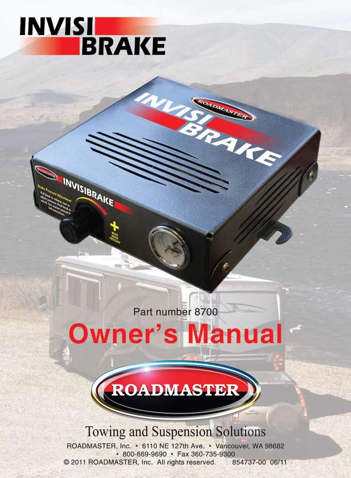
2 Welcome to the ROADMASTER family! This manual has been prepared to acquaint you with the operation of your InvisiBrake supplemental braking system and to provide you with important safety information. Read this manual completely. Understand how to operate InvisiBrake and carefully follow the instructions and safety precautions. Your InvisiBrake has a one-year limited warranty. To qualify for your warranty, fill out and return the enclosed product registration card within 30 days of purchase. We thank you for your patronage and greatly appreciate your discerning taste. InvisiBrake specifications Controller height...2¾ inches Controller width...8¾ inches Controller length...8¾ inches Voltage...12 volts DC Fuse size amp Operating temperature range to +150 F (-19 to +66 C) Maximum amperage draw amps Idle amperage draw...6 ma Battery recharging rate...up to 2 amps Approximate maximum air pressure psi Save this manual Save this manual for future reference. It contains important information relative to safety and use. Therefore, make sure this manual is always with you when you re towing. You can download or print a copy of the most current manual at (under Support'). Read all instructions before operating InvisiBrake. Failure to understand how to operate InvisiBrake could result in property damage, personal injury or even death. The InvisiBrake serial number is on a label on the front of the controller. You will need this number when you fill out your product registration card. Write down the serial number in the space below and retain for future reference. Serial number: All illustrations and specifications contained herein are based on the latest information available at the time of publication. ROADMAS- TER, Inc. reserves the right to make changes, at any time, without notice, in material, specifications and models, or to discontinue models. IMPORTANT NOTICE! Safety Definitions These instructions contain information that is very important to know and understand. This information is provided for safety and to prevent equipment problems. To help recognize this information, observe the following symbols: WARNING indicates a potentially hazardous situation which, if not avoided, could result in property damage, serious personal injury or even death. CAUTION indicates a potentially hazardous situation which, if not avoided, may result in property damage, or minor or moderate personal injury. CAUTION CAUTION used without the safety alert symbol indicates a potentially hazardous situation which, if not avoided, may result in property damage. NOTE Refers to important information and is placed in italic type. It is recommended that you take special notice of these items.

 452110.")
 450431-10.")


 9 945203-00.")


 17 452111.")
3 Components part number description InvisiBrake controller, complete InvisiBrake compressor only (not shown) InvisiBrake kip valve only (not shown) InvisiBrake circuit board only (not shown) InvisiBrake regulator only (not shown) plastic bonnet ring for regulator cable only air cylinder only pulley only brake pedal clamp (with mounting nuts and bolts) monitor wire patch cord car side monitor wire, 15 feet long (not shown) motorhome side monitor wire, 50 feet long (not shown) four-wire harness: break away, power and ground break away cable break away switch, pin and ring break away pin and ring only motorhome monitor LED audio signal circuit board vacuum check valve /8" air line (not shown) /4" nylon vacuum line (not shown) /4" rubber vacuum hose, one foot (not shown) /8" rubber vacuum hose (not shown) /2" rubber vacuum hose (not shown) /8" vacuum line tee /2" vacuum line tee four-wire flat harness: towed lighting 5 (Components not shown to scale)


4 For vehicles with brake pedal presets Make certain that the cable and brake pedal clamp assembly were installed with the brake pedal as close to the driver s seat as possible. Make certain that the brake pedal is at that position when towing. As an option, the brake pedal may be moved to the desired position and disabled. Do not rely on a mental note to never move the brake pedal. unintended braking and eventual brake failure, which may result in property damage, personal injury or even death. Preparations for towing The installer should have pre-set the braking pressure to a level appropriate to your vehicle. If the Invisi- Brake brake pressure is ever adjusted, or if InvisiBrake is transferred to another vehicle, follow all instructions in the section titled How to change the brake pressure. 1. Connect the monitor wire patch cord plug the monitor wire patch cord (Figure 1) into the front of the towed vehicle and the rear of the motorhome. Allow enough slack to prevent the patch cord from being pulled loose when the motorhome turns. If the cord is too long, wrap it around or through the umbilical cord. 2. Connect the break away cable Attach one of the snap hooks (Figure 2) to the large ring on the break away pin (Figure 2) at the front of the towed vehicle, then clip the other end of the break away cable to the rear of the motorhome, close to the center. Note: see the warnings on this page. 3. Turn the motorhome park lights on this will activate the InvisiBrake charge circuit, which will provide a constant trickle charge to the vehicle s battery during towing. 4. Enjoy your travels. Figure 1 When connecting the break away system, always check the following: Connect the cable at the rear of the motorhome, close to the center. Connecting the cable toward either side of the motorhome may cause the break away pin to be pulled when the motorhome turns, activating the break away system. Be certain there are no obstructions which would prevent the cable from pulling freely away from the break away switch. Do not wrap the cable around anything doing so could keep the cable from pulling the break away pin, preventing the system from activating in a break away. Make certain the cable is the correct length The cable must be long enough to prevent the break away pin from being pulled out during normal towing make certain there is enough slack to allow for sharp turns. If the cable is not long enough, the break away system will activate even though the towed vehicle has not detached. The break away cable must be longer than the safety cables. This will prevent the break away continued on next page Figure 2 2
5 Preparations for towing continued from previous page system from activating if a component of the towing system has separated, but the towed vehicle is still held by the safety cables. Make certain that the cable is not too long it should not hang down to the extent that it may catch on obstructions, or drag on the ground. This much slack could allow the cable to be pulled inadvertently, activating the break away system. If you have a telescoping tow bar, allow enough slack for the tow bar arms to be fully extended. Except to test the break away system or adjust the braking pressure, leave the break away pin in place, even when the vehicle is not being towed. If the pin is not in place, the InvisiBrake compressor will run constantly, which will damage the compressor and drain the vehicle s battery. property damage, personal injury or even death. Protection modes Extended braking protection To protect the towed vehicle s brakes, InvisiBrake will automatically release braking pressure after an extended period (approximately 15 seconds) of continuous braking for example, someone who constantly drives with their foot on the brakes. To regain supplemental braking in the towed vehicle, release and depress the motorhome brake pedal. Note: motorhomes with exhaust brakes may activate the brake lights, causing InvisiBrake to brake the towed vehicle. InvisiBrake automatically protects the towed vehicle s brakes by releasing braking pressure after 15 seconds of continuous braking. When the exhaust brakes disengage, InvisiBrake resumes normal operation. Responding to an audio alert If, for any reason, the towed vehicle s brakes are applied continuously (for approximately 20 seconds), you will hear an audible alarm. In addition to the audio alert, the monitor LED will be illuminated continuously. Stop immediately. The audio alert and illuminated LED are indicating that the towed vehicle's brake pedal is being constantly depressed. Significant brake system damage to the towed vehicle will occur. Identify and correct the cause of the audio alert before using InvisiBrake. If you are unable to determine the cause of the audible alarm, disconnect the cable from the brake pedal arm in the towed vehicle. CAUTION If InvisiBrake signals you with an audio alert, stop immediately. Identify and correct the cause of the alarm before using InvisiBrake. Failure to respond to an audio alert, as indicated above, may cause significant non-warranty damage to the towed vehicle's tires and brake system, as well as other consequential damage. How to change the brake pressure Based on your personal preferences, if you d like to increase or decrease the braking pressure follow the steps below. Before changing the brake pressure, read this section completely. The degree to which the brake pressure setting will affect the motorhome will vary, depending on the size and weight of the motorhome in comparison to the size and weight of the towed vehicle Brake pressure set too high a sharp pull at the motorhome may indicate that the brake pressure is set too high in this case, you may choose to lower the setting until the towed vehicle brakes with less force. See If necessary, change the brake pressure setting, on the next page. It is possible to lower the brake pressure setting to the point that it negates the benefit of the supplemental braking system and break away. Insufficient brake pressure will lengthen stopping distance. property damage, personal injury or even death. Brake pressure set too low if the combination of vehicles takes longer to stop than the motorhome alone, you may choose to raise the setting. See If necessary, change the brake pressure setting, on the next page. If brake pressure is set too high, InvisiBrake will apply excessive force to the towed vehicle s brake pedal, which will cause tire and brake system damage, as well as other consequential, non-warranty damage. continued on next page 3
6 How to change the brake pressure continued from preceding page property damage, personal injury or even death. If necessary, change the brake pressure setting 1. Pull the break away pin (Figure 2). The pressure gauge on the controller (see page one) will display the current braking pressure. CAUTION Reinsert the brake away pin within five minutes, or premature compressor failure may result. 2. Pull out on the brake pressure adjustment knob (see page one) to unlock it. Turn the knob clockwise to increase the braking pressure or counterclockwise to decrease the braking pressure. 3. Adjust the pressure by no more than 10 psi. 4. Push the brake pressure adjustment knob in to lock it in place. Reinsert the break away pin. 5. Test drive the motorhome and towed vehicle for a short distance, making six to eight stops. If necessary, adjust again until you are satisfied with the brake pressure setting. Every time you adjust the brake pressure, you must test drive the motorhome and towed vehicle. After repetitive braking, check for excessive heat near the center of the towed vehicle s wheels this indicates that the brakes are overheating and that the brake pressure is set too high. You must lower the braking pressure and retest until the brakes are not excessively hot. brake failure, resulting in property damage, personal injury or even death. Test InvisiBrake Following is a comprehensive test of InvisiBrake functions. We recommend that you perform this test before each towing season. Test InvisiBrake main functions The following tests can be performed with the motorhome and towed vehicle stationary. 1. Confirm braking with the motorhome engine running, depress and hold the motorhome brake pedal down. The towed vehicle s brake pedal will be depressed. Then, release the motorhome brake pedal. At the towed vehicle, the brake pedal will retract. 2. Confirm that the motorhome monitor is functioning the LED will illuminate after the motorhome s brake pedal is depressed and stop illuminating when the brake pedal is released. 3. Confirm the proper operation of the extended braking protection mode depress and hold the motorhome s brake pedal down. The towed vehicle s brake pedal will be depressed. After approximately 15 seconds, the brake pedal will retract, even though the motorhome brake pedal is still depressed. 4. Confirm the proper operation of the audio alert in the towed vehicle, depress and hold the brake pedal down. After approximately 20 seconds, the audio alert will sound in the motorhome. (To cancel the audio alert, release the towed vehicle s brake pedal.) Test the break away system 1. Pull the large ring on the break away pin (Figure 2) out of the break away switch (Figure 2). The towed vehicle s brake pedal will be depressed when the pin is pulled. Insert the pin back into the switch. The brake pedal will be released. If InvisiBrake fails any of the above tests, you must refer to the Troubleshooting section and repair the fault before towing. property damage, personal injury or even death. 4
7 Troubleshooting Symptom Nothing happens after proper installation. The motorhome monitor LED does not illuminate, even though the brakes in the towed vehicle are being applied. InvisiBrake doesn't stop braking when the motorhome brakes are released. It keeps braking for about 15 seconds. Turning the hazard lights on causes InvisiBrake to cycle on and off with the lights for a few seconds. I m not braking the motorhome, but the motorhome monitor light stays on. Solution Make certain the 20-amp fuse was installed during the installation. Make certain that InvisiBrake is connected to a full-time power supply some vehicles have an automatic shut off feature, some require you to pull a fuse for towing and some require the battery to be disconnected for towing. Make certain that the check valve was installed with the arrow pointing toward the engine. Check all electrical connections, with particular attention to the ground between the motorhome and towed vehicle. Make certain that InvisiBrake is receiving a brake light signal from the motorhome. The InvisiBrake wiring was connected downstream of the diodes. Reconnect the wiring upstream of the diodes. Inspect the brake pedal clamp, pulley and cable anchor bracket. Make certain that they are installed correctly and that the cable is routed properly. The operating temperature range is between -2 and +150 F (-19 to +66 C). InvisiBrake will not operate at temperatures above or below this range. Make certain the brake light fuse was replaced in the towed vehicle. Make certain that the monitor wire patch cord between the two vehicles is securely connected. Make certain that there is an electrical ground between the motorhome and the towed vehicle. Check for power at the stop light switch, at the front of the vehicle and at the LED in the motorhome. Hold the towed vehicle brake pedal down for approximately 20 seconds. If the audio alert activates, then one of the two connections to the LED may have worked loose. Check both the power and the ground connections. The monitor LED is connected to the towed vehicle s brake light circuit. If the fuse in the circuit is blown, the LED will not operate. Check the towed vehicle s brake lights if they illuminate when the brake pedal is depressed, the fuse is good. Was the optional Brake-Lite Relay installed? If so, make certain that the monitor wire is connected to the towed vehicle s brake light wire after the brake light switch, but before the Brake-Lite Relay connecting the wire anywhere else will prevent the monitor LED from functioning. If the towed vehicle has been wired for towing (as opposed to installing a bulb and socket kit), diodes must be attached to the wires. If diodes are not attached, electrical feedback through the brake light wire will prevent InvisiBrake from releasing until the extended braking protection mode overrides the brake light signal, after approximately 15 seconds. This is normal the hazard lights use the brake light circuit, which is what activates InvisiBrake. It takes InvisiBrake three or four cycles to recognize that this is not a brake light signal. This cycle will start over each time you brake the motorhome while the hazard lights are on. Readjust the brake pedal clamp. The cable is bound or obstructed. Inspect the cable assembly from the brake pedal to the cable anchor bracket. Incorrect cable adjustment refer to the installation instructions for proper adjustment. 5
8 Limited warranty 1. WARRANTY 1a. WARRANTY OF CONFORMITY AT TIME OF SALE ROADMASTER, Inc. warrants that at the time of sale of this product it will be free from defects in material and manufacture and will conform to ROADMASTER S specifications for the product. 1b. CONDITIONAL ONE-YEAR WARRANTY In addition to the preceding time-of-sale warranty, if the product registration card is completely and accurately filled out and mailed to ROADMASTER within thirty (30) days of purchase, ROADMASTER will provide an additional warranty that for a period of one year after sale the product will remain in good working order, PROVIDED THAT the product is installed and maintained in accordance with ROADMASTER S instructions and is not subjected to: (a) alteration or unauthorized repairs or repairs by anyone other than ROADMASTER or a ROADMASTER-authorized service center, (b) misuse, abuse, commercial use, or improper maintenance, (c) Acts of God (including without limitation hurricanes, tornadoes, floods, or other severe weather or natural phenomena), (d) failures due to products not supplied by ROADMASTER, or (e) other treatments, uses, or installations for which the product was not intended. This warranty extends only to the first retail purchaser-consumer of the product and is not transferable. EXTENDED WARRANTY PERIOD: If ROADMASTER receives the product registration card, completely and accurately filled out, within thirty (30) days of purchase, ROADMASTER will enlarge the one-year warranty period in the preceding paragraph to a period of two years. 2. DISCLAIMER OF OTHER WARRANTIES The preceding warranties are the exclusive and sole express warranties given by ROADMASTER. They supersede any prior, contrary or additional representations, whether oral or written. No agent, representative, dealer or employee has the authority to alter or increase the obligations or limitations of this warranty. Any implied warranties, including the WARRANTY OF MERCHANTABILITY and any WARRANTY OF FITNESS FOR A PARTICULAR PUR- POSE, are limited in duration to thirty days or the term of the applicable express warranty provided above, whichever is longer. Some states do not allow limitations on how long an implied warranty lasts, so the above limitation may not apply to you. 3. EXCLUSIVE REMEDY FOR ANY NONCONFORMI- TIES If during the applicable Warranty Period, the product does not conform to the preceding Warranties, notify ROAD- MASTER as provided below, and within a reasonable time ROADMASTER will provide, at its option, one of the following: (1) replacement components for any nonconforming or defective product or components or (2) the percentage of the purchase price for the nonconforming product equal to the percentage of the Warranty Period remaining when ROAD- MASTER is notified of the nonconformity. ROADMASTER will, at its option, (a) use new and/or reconditioned parts in performing warranty repairs and making replacement products, (b) use parts or products of original or improved design in the repair or replacement. If ROADMASTER repairs or replaces a product, its warranty continues for the remaining portion of the original Warranty Period or 60 days from the date of the return shipment to the customer, whichever is greater. All replaced products and all parts removed from repaired products become the property of ROAD- MASTER. ROADMASTER will not provide, and will not be liable for, labor, costs of removal or reinstallation of components, disposal, shipping, freight, taxes, or other incidental charges. THESE REMEDIES ARE THE EXCLUSIVE AND SOLE REMEDIES FOR ANY BREACH OF WARRANTY. For any breach of warranty, the Owner must telephone ROADMASTER at within thirty (30) days after discovering the nonconformity. Do not return any product without first calling ROADMASTER and getting a return authorization number. Returned products must include the return authorization number and a copy of the original invoice, bill or other proof of the date of purchase. The date of purchase must coincide with the original warranty registration card on file. ROADMASTER will authorize (a) shipment of the product to ROADMASTER or (b) repair or replacement at the nearest warranty service center in both cases with shipping at your expense. Do not purchase replacement parts or pay for repair labor you will not be reimbursed. Compliance with the requirements of this paragraph is a condition to coverage under the Warranty: if these requirements are not complied with, ROADMAS- TER will have no obligation to provide any remedy for any breach of warranty. 4. DISCLAIMER OF INCIDENTAL AND CONSEQUENTIAL DAMAGES IN NO EVENT SHALL ROADMASTER BE LIABLE FOR ANY INCIDENTAL, SPECIAL, INDIRECT OR CONSE- QUENTIAL DAMAGES, WHETHER RESULTING FROM NONDELIVERY OR FROM THE USE, MISUSE OR IN- ABILITY TO USE THE PRODUCT OR FROM DEFECTS IN THE PRODUCT. Some states do not allow the exclusion or limitation of incidental or consequential damages, so the above limitation may not apply to you. 5. APPLICABLE LAW This Warranty will be interpreted, construed, and enforced in all respects in accordance with the laws of the State of Washington, without reference to its choice of law rules. The U.N. Convention on Contracts for the International Sale of Goods will not apply to this Warranty. 6. SEVERABILITY If any provision of this warranty is found to be invalid or unenforceable, then the remainder shall have full force and effect, and the invalid provision shall be partially enforced to the maximum extent permitted by law to effectuate the purpose of the agreement. 7. ADDRESS FOR NOTICES TO ROADMASTER ROADMASTER, Inc., 6110 NE 127th Ave, Vancouver, WA This warranty gives you specific legal rights, and you may also have other rights which vary from State to State.
Installation Instructions
 85-3414 rev. 02 11-09 Installation Instructions Thank you for purchasing this anti-sway bar kit. Please read through these instructions before installation. Rear Anti-Sway Bar Kit for the Monaco Diplomat
Installation Instructions
 85-3214 rev. 07 03-11 Installation Instructions Thank you for purchasing this anti-sway bar kit. Please read through these instructions before installation. Rear Anti-Sway Bar Kit Freightliner FL Series
Installation Instructions
 85-3909 rev. 01 09-09 Installation Instructions Thank you for purchasing this anti-sway bar kit. Please read through these instructions before installation. Rear Anti-Sway Bar Kit for Chevrolet G30 part
Installation Instructions
 85-3910 rev. 03 01-18 Installation Instructions Thank you for purchasing the antisway bar kit. Please read through these instructions before installation. Rear Anti-Sway Bar Kit for Ford F-250/F-350 part
Installation Instructions
 85-4209 rev. 05 11-18 Installation Instructions Thank you for purchasing this anti-sway bar kit. Please read through these instructions before installation. Factory Replacement Anti-Sway Bar Kit part #1129-135
Installation Instructions
 85-3207 rev. 03 05-06 Installation Instructions Thank you for purchasing this anti-sway bar kit. Please read through these instructions before installation. Rear Anti-Sway Bar Kit for the Freightliner
Installation Instructions
 85-3700 rev. 08 05-18 Installation Instructions Thank you for purchasing this antisway bar kit. Please read through these instructions before installation. Front Anti-Sway Bar Kit for the F53 Chassis part
Installation Instructions
 85-3209 rev. 07 03-11 Installation Instructions Thank you for purchasing this anti-sway bar kit. Please read through these instructions before installation. Front Anti-Sway Bar Kit for Workhorse W22, Holiday
Installation Instructions
 85-3511 rev. 04 11-15 Installation Instructions Polyurethane Bushing Kit for Ford F-53 (Front) (replaces OE bushings and brackets) part #4139-127 1-5/8 diameter INTRODUCTION Thank you for purchasing this
Installation Instructions
 85-4592 rev. 08 02-18 Installation Instructions Thank you for purchasing our sway bar kit. Please read through these instructions before installation. Auxiliary Rear Anti-Sway Bar Kit for Ford F53 part
Installation Instructions
 85-3847 rev. 01 09-09 Installation Instructions Thank you for purchasing this anti-sway bar kit. Please read through these instructions before installation. Front Anti-Sway Bar TruTrac Bar Combo Kit for
Installation Instructions
 85-5029 rev. 03 06-17 Installation Instructions Thank you for purchasing our anti-sway bar kit. Please read through these instructions before installation. Rear Anti-Sway Bar Kit for Workhorse W22, Holiday
Installation Instructions
 85-3195 rev. 12 04-18 Installation Instructions Thank you for purchasing this antisway bar kit. Please read through these instructions before installation. Part #1139-117 Rear Anti-Sway Bar Kit 1½ diameter
Installation Instructions
 85-4341 rev. 04 10-15 Installation Instructions Thank you for purchasing this antisway bar kit. Please read through these instructions before installation. Rear Anti-Sway Bar Kit for Chevy 2500/3500/4500
Installation Instructions
 85-3180 rev. 07 03-14 Installation Instructions Thank you for purchasing this antisway bar kit. Please read through these instructions before installation. Front Anti-Sway Bar Kit for the Ford E350/450
Table of contents. InvisiBrake specifications
 InvisiBrake specifications Controller height...2¾ inches Controller width...8¾ inches Controller length...8¾ inches Voltage...12 volts DC Fuse size... 20 amp Operating temperature range... -2 to +150 F
Installation Instructions
 8-318 rev. 02 03-06 Installation Instructions Thank you for purchasing this anti-sway bar kit. Please read through these instructions before installation. Rear Anti-Sway Bar Kit for the Dodge 200/ 300
Installation Instructions
 BrakeMaster 9100 and 9160 for motorhomes with air or air over hydraulic brakes Second Motorhome Kit Installation Instructions Part number 98200 Time Tested Time Proven ROADMASTER, Inc. 6110 NE 127th Ave.
Installation Instructions
 patent pending Portable Proportional Braking System Installation Instructions Part number 9400 Towing and Suspension Solutions ROADMASTER, Inc. 6110 NE 127th Ave. Vancouver, WA 98682 800-669-9690 Fax 360-735-9300
Welcome to the ROADMASTER family!
 Welcome to the ROADMASTER family! This manual has been prepared to acquaint you with the operation, care and maintenance of your BrakeMaster supplemental braking system and to provide you with important
Extend your warranty for an additional year. See inside front cover for details. for FREE!
 Extend your warranty for an additional year for FREE! See inside front cover for details. 2007-2018 ROADMASTER, Inc. All rights reserved. 853326-24 01-18 WELCOME TO THE ROADMASTER FAMILY! This manual has
ROADMASTER, Inc NE 127th Ave. Vancouver, WA Fax roadmasterinc.com ROADMASTER, Inc.
 ROADMASTER, Inc. 6110 NE 127th Ave. Vancouver, WA 98682 800-669-9690 Fax 360-735-9300 roadmasterinc.com 2008-2017 ROADMASTER, Inc. All rights reserved. 853600-05 11/17 Read all instructions before installing
ROADMASTER, Inc NE 127th Ave. Vancouver, WA Fax ROADMASTER, Inc. All rights reserved
 ROADMASTER, Inc. 6110 NE 127th Ave. Vancouver, WA 98682 800-669-9690 Fax 360-735-9300 2011-2018 ROADMASTER, Inc. All rights reserved. 854828-24 09.18 InvisiBrake specifications Controller height...2¾ inches
for 2017 ROADMASTER, Inc. All rights reserved.
 nty warra r r u o ea dy Exten dditional y a for an! E E FR over ont c r f for e d nsi tails. See i for de 2017 ROADMASTER, Inc. All rights reserved. 855616-04 09/17 Welcome to the Roadmaster family! This
Installation Instructions
 Portable Proportional Braking System Installation Instructions Part number 9400 Time Tested Time Proven ROADMASTER, Inc. 6110 NE 127th Ave. Vancouver, WA 98682 800-669-9690 Fax 360-735-9300 roadmasterinc.com
Time Tested Time Proven
 Portable Proportional Braking System Owner s Manual Entire contents of manual must be read by owner Extend your warranty for an additional year for FREE! See inside front cover for details. Part number
CAUTION. Even Brakes with a black cable need second vehicle kit Even Brakes with a blue cable need second vehicle kit 98450
 cable not included cable not included Even Brakes with a blue cable need second vehicle kit 98450 Even Brakes with a black cable need second vehicle kit 98400 Check the Even Brake serial number before
DeZURIK AFR3 Filter Regulator Used on Pneumatic Cylinder Actuators
 AFR3 Filter Regulator Used on Pneumatic Cylinder Actuators Instructions D11033 August 2013 Instructions These instructions provide information about AFR3 Filter Regulators. They are for use by personnel
Quality Towing Systems Since Owner's s Manual THIS MANUAL MUST BE READ COMPLETELY BY OWNER
 Quality Towing Systems Since 1974 Owner's s Manual THIS MANUAL MUST BE READ COMPLETELY BY OWNER R O A D M A S T E R, I N C. Welcome to the ROADMASTER family! This manual has been prepared to acquaint you
Installation Instructions
 Replacement Proportioning Valve for BrakeMaster model 9060 Installation Instructions Part number 900001 Time Tested Time Proven ROADMASTER, Inc. 6110 NE 127th Ave. Vancouver, WA 98682 800-669-9690 Fax
for ROADMASTER, Inc. All rights reserved.
 ranty r war ar u o y e d Exten dditional y a n a for! E E R F ver co front for e d i s n tails. See i for de 2003-2017 ROADMASTER, Inc. All rights reserved. 853328-25 09.17 WELCOME TO THE ROADMASTER FAMILY!
Table of contents. InvisiBrake specifications
 InvisiBrake specifications Controller height...2¾ inches Controller width...8¾ inches Controller length...8¾ inches Voltage...12 volts DC Fuse size... 20 amp Operating temperature range... -2 to +150 F
CLASSIC II Portable Braking System
 39495 CLASSIC II Portable Braking System Inventor and Leader in Portable Technology! INSTRUCTIONS NEED HELP? CALL - 1-800-470-2287 (MONDAY - FRIDAY 8AM - 5PM CST) WARNING Read all instructions before installing
Rechargeable Inflator
 See Warranty on page 6 for important information about commercial use of this product. Operating Instructions and Parts Manual HDC230 Please read and save these instructions. Read carefully before attempting
Power. On Your Terms.
 Power. On Your Terms. 10 YEAR LIMITED WARRANTY PHI 1310 TM 1 SIMPLIPHI POWER, INC. REV102016 10 YEAR LIMITED WARRANTY: PHI 1310 TM LIMITED PRO-RATED WARRANTY COVERAGE The SimpliPhi Power PHI 1310 as supplied
Extend your warranty for an additional year. See inside front cover for details. for FREE!
 Extend your warranty for an additional year for FREE! See inside front cover for details. 2007-2017 ROADMASTER, Inc. All rights reserved. 851536-23 11.17 WELCOME TO THE ROADMASTER FAMILY! This manual has
10 Year Limited Warranty
 Power. On Your Terms. 10 Year Limited Warranty PHI 2.7 TM PHI 3.5 TM 60A SIMPLIPHI POWER, INC. REV020618 10 Year Limited Warranty: PHI 2.7 TM PHI 3.5 TM 60A 24V 48V Limited Pro-Rated Warranty Coverage
Installation & Operators Manual
 Installation & Operators Manual Model Serial Number Purchase Date 2007-2008 SegVator, LLC Patent Pending All Rights Reserved Important Safety Information Make sure the vehicle has a properly installed
INSTALLATION GUIDE. Universal System for Zero Turn Mowers
 INSTALLATION GUIDE Universal System for Zero Turn Mowers Table of Contents General Information 1 Important Notice to Purchaser 2 Specifications 2 Intended Usage 2 Important Information 3 General Safety
DeZURIK KUL KNIFE GATE VALVES
 KUL KNIFE GATE VALVES Instruction D11025 September 2013 Instructions These instructions are intended for personnel who are responsible for the installation, operation and maintenance of your KUL knife
PASSENGER AND LIGHT TRUCK TIRE LIMITED WARRANTY AND ADJUSTMENT POLICY
 PASSENGER AND LIGHT TRUCK TIRE LIMITED WARRANTY AND ADJUSTMENT POLICY Includes all Applicable Information on Mileage Warranty, and Customer Satisfaction Trial In addition to the valuable Warranty information
Guide and Manual Before using the Lunicycle, READ THROUGH THESE INSTRUCTIONS COMPLETELY! Inventist, Inc Inventist Inc.
 Guide and Manual Before using the Lunicycle, READ THROUGH THESE INSTRUCTIONS COMPLETELY! Inventist, Inc. 2015 Inventist Inc. WARNING Whenever you ride the Lunicycle you risk serious injury or death from
APCO CRF-100A RUBBER FLAPPER SWING CHECK VALVES
 APCO CRF-100A RUBBER FLAPPER SWING CHECK VALVES Instruction D12043 June 2016 DeZURIK Instructions These instructions provide installation, operation and maintenance information for APCO CRF-100A Rubber
FLEETWOOD TRAVEL TRAILER SLIDEOUT SYSTEM OWNER S MANUAL
 FLEETWOOD TRAVEL TRAILER SLIDEOUT SYSTEM OWNER S MANUAL 82-S0150-01 REV. 1 April, 2002 TABLE OF CONTENTS PAGE # OPERATIONS MANUAL... 1 1. SYSTEM DESCRIPTION... 1 1.1 MAJOR COMPONENTS... 1 2. HOW TO OPERATE
Model AS-RC3260 TV Cart. Rolling Cart for Audio Mount System & Flat Panel TVs
 Model AS-RC3260 TV Cart Rolling Cart for Audio Mount System & Flat Panel TVs GETTING STARTED Introduction Congratulations on the purchase of your new Helios AS-RC3260 Rolling Cart. For maximum benefit,
END USER TERMS OF USE
 END USER TERMS OF USE The following is the End Users Terms of Use as it currently appears in the Mobileye User Manual and Warranty information. This is here for your review and information; it is subject
PVI 1800/PVI Residential/Commercial Grid-Tied Photovoltaic Inverter WARRANTY MANUAL. Subject to Change REV , Solectria Renewables
 PVI 1800/PVI 2500 WARRANTY MANUAL Residential/Commercial Grid-Tied Photovoltaic Inverter 2009, Solectria Renewables Subject to Change REV 10.09 1 Product Warranty & RMA Policy 1.1 Warranty Policy The Solectria
GC-1. Roof and Gutter De-Icing Control Installation and Operating Instructions FOR EXTERIOR INSTALLATION ONLY
 GC-1 Roof and Gutter De-Icing Control Installation and Operating Instructions FOR EXTERIOR INSTALLATION ONLY GENERAL INFORMATION The GC-1 heating cable controller has been designed and manufactured for
A/C PRESSURE MONITOR INSTALLATION INSTRUCTIONS SYSTEM OPERATION GREEN INDICATOR LIGHT
 A/C PRESSURE MONITOR INSTALLATION INSTRUCTIONS Do not attempt to clean or inspect anything while the engine is running. Cleaning and inspection must be done by a certified mechanic. All A/C service must
StormPro BA Series Sump Pump
 Page 1 of 8 Marks & Meanings DANGER: Keep the pump equipment out of the reach of children! Warns that the failure to follow the directions given could cause serious risk to individuals or objects. WARNING:
The Da-Lite Difference.
 The Da-Lite Difference. Instruction Book for Large Advantage Electrol DA-LITE SCREEN COMPANY, INC. 3100 North Detroit Street Post Office Box 137 Warsaw, Indiana 46581-0137 Phone: 574-267-8101 800-622-3737
DeZURIK 2 20" BOS BUTTERFLY VALVES
 2 20" BOS BUTTERFLY VALVES Instruction D10459 October 2013 2-20 BOS Butterfly Valves Instructions These instructions provide information about BOS Butterfly Valves. They are for use by personnel who are
Select II Portable Braking System
 39523 Select II Portable Braking System Inventor and Leader in Portable Technology! INSTRUCTIONS NEED HELP? CALL - 1-800-470-2287 (MONDAY - FRIDAY 8AM - 5PM CST) WARNING Read all instructions before installing
Time Tested Time Proven
 U.S. patent number 6,164,897 Part number 2000-1 Owner's Manual Entire contents of manual must be read by owner CAUTION This dolly will not accommodate all vehicles. The size and shape of any particular
Installation Instructions
 BrakeMaster 9000 and 9060 Second Motorhome Kit part number 98300 Installation Instructions Quality Towing Systems since 1974 ROADMASTER, Inc. 5602 N.E. Skyport Way Portland, OR 97218 800-669-9690 Fax 503-288-8900
Please Read this manual before operating your UltraRide Suspension, and keep it for future reference.
 OWNER S MANUAL Model # 800M1300 Lot/Serial # Questions? Contact this Professional Installer : Company : Phone : ELECTRONIC AIR CONTROL KIT Installer : Date : MN-769 80003011 MAR 20, 2013 Please Read this
SYSTEM MANUAL. Automated Motorized Hydraulic Traffic Controller. Revision CS72-HTC
 CS72-HTC SYSTEM MANUAL Automated Motorized Hydraulic Traffic Controller Revision 2002.01 Spike Systems 3623 S. Seventh Street Phoenix, Arizona 85040 Phone: (602) 243-0291 Fax: (602) 243-0294 Hydraulic
INSTALLATION/OWNERS MANUAL
 INSTALLATION/OWNERS MANUAL XOBP12D PREPARATION Getting Started Thank you for purchasing the Dual Electronics XOBP12D Bandpass Subwoofer System. Although Dual has attempted to make sure all of the information
Model T2642 Wall Mount. Television Wall Mount with Tilt Option
 Model T2642 Wall Mount Television Wall Mount with Tilt Option Getting Started Introduction Congratulations on the purchase of your new Audio Solutions T2642 Television Wall Mount. For maximum benefit,
LifeGuardLift. LifeGuard Power Lift Model #100287A OWNERS MANUAL. Rev: 2/14/11
 LifeGuardLift OWNERS MANUAL LifeGuard Power Lift Model #100287A Rev: 2/14/11 Table of Contents 1. ASSEMBLY INSTRUCTIONS A. Lift Assembly B. Setup C. Disassembly 2. CONTROL SYSTEM A. Batteries B. Battery
WARNINGS, CAUTIONS AND NOTES
 Welcome Please read this manual thoroughly before installing and operating your new Power Bright Power Inverter. This manual contains information you need to obtain the performance required for your application.
US Patent 0540, 400 Other Patents Pending. Read this manual completely before assembling and riding our PET PRO-FLEX 500. Always wear a Helmet!
 US Patent 0540, 400 Other Patents Pending Read this manual completely before assembling and riding our 500 Always wear a Helmet! Priority Electric Transportation, LLC. 1007 West College Ave. #293 Santa
TABLE OF CONTENTS. If you have any questions after reading these instructions, please call BrakeBuddy customer service at
 TABLE OF CONTENTS Congratulations on the purchase of your new BrakeBuddy! The BrakeBuddy was designed and built as an auxiliary braking system to operate in conjunction with the existing braking system
HLY-1111 HEAD TEMPERATURE GAUGE
 HLY-1111 HEAD TEMPERATURE GAUGE Introduction: The Odyssey gauge series from Dakota Digital, Inc. incorporates the reliability and quality of our standard gauges, along with several unique features and
WARRANTY POLICY. Grid-Tied Photovoltaic Inverters. Revision D. 2014, Solectria Renewables, LLC DOCIN
 WARRANTY POLICY Revision D 2014, Solectria Renewables, LLC DOCIN-070360 1 Product Warranty & RMA Policy 1. Warranty Policy Warranty Registration: It is important to have updated information about the inverter
BX7322 Adventurer Tow Bar Operator Manual & Installation Instructions
 Please visit www.blueox.com for the latest version of these installation instructions. BX7322 Operator Manual & Installation Instructions Serial Number (5,000 lb) 2 Inch Coupler 292-1263 Rev J Page 1 of
Installation / Operation Instructions Sunnex ORION Series Exam Lights
 Installation / Operation Instructions Sunnex ORION Series Exam Lights OR-120 OR-127 OR-220 OR-227 Models: OR-300 OR-400 OR-500 OR-600 1. APPLICATIONS The Sunnex ORION Series light was designed specifically
Kit INSTALLATION GUIDE. For maximum effectiveness and safety, please read these instructions completely before proceeding with installation.
 Kit 25690 MN-369 (111512) ECR 8349 INSTALLATION GUIDE For maximum effectiveness and safety, please read these instructions completely before proceeding with installation. Failure to read these instructions
ODY-05-2 VOLTMETER FOR REMOTE MONITORING
 ODY-05-2 VOLTMETER FOR REMOTE MONITORING Introduction: The Odyssey gauge series from Dakota Digital, Inc. incorporates the reliability and quality of our standard gauges, along with several unique features
DeZURIK 2-24 (50-600mm) KGN-RSB BI-DIRECTIONAL CAST STAINLESS STEEL KNIFE GATE VALVES
 KGN-RSB BI-DIRECTIONAL CAST STAINLESS STEEL KNIFE GATE VALVES") 2-24 (50-600mm) KGN-RSB BI-DIRECTIONAL CAST STAINLESS STEEL KNIFE GATE VALVES Instruction D11023 October 2016 Instructions These instructions provide information about KGN-RSB Knife Gate Valves. They are
2-24 (50-600mm) KGN-RSB BI-DIRECTIONAL CAST STAINLESS STEEL KNIFE GATE VALVES Instruction D11023 October 2016 Instructions These instructions provide information about KGN-RSB Knife Gate Valves. They are
User s Manual and Operating Instructions
 User s Manual and Operating Instructions Model Numbers: CL-36-BDF-A, CL-42-BDF-A, CL-48-BDF-A E355088 READ AND SAVE THESE INSTRUCTIONS IMPORTANT: Read and understand all of the instructions in this manual
PVI 60KW, PVI 82KW, PVI 95KW
 PVI 60KW PVI 82KW PVI 95KW WARRANTY MANUAL Commercial, Grid-Tied Photovoltaic Inverters 2008, Solectria Renewables LLC Subject to Change DOC-020099 rev 024 1 1 Product Warranty & RMA Policy Warranty Policy
60 PSI Boost Gauge. For Product Numbers: MT-DV01_60, MT-WDV01_60
 60 PSI Boost Gauge For Product Numbers: MT-DV01_60, MT-WDV01_60 Red: 12v Constant (un-switched) Source (+) Orange: 12v Dimmer (switched) Source (+) (optional) White: 12v Ignition (switched) Source (+)
Microscope light manual
 Microscope light manual LS-12 and LS-14 LS-12 LS-14 1/9 Content Overview... 3 Mounting... 4 Light adjustment... 5 Mirror... 6 Filters... 6 Replacing microscope light... 7 Technical data... 8 Troubleshooting...
The Da-Lite Difference.
 The Da-Lite Difference. Instruction Book for Boardroom Electrol DA-LITE SCREEN COMPANY, INC. 3100 North Detroit Street Post Office Box 137 Warsaw, Indiana 46581-0137 Phone: 574-267-8101 800-622-3737 Fax:
Remote Vehicle Control System. Keyless Entry & Remote Start System
 1 Remote Vehicle Control System PC 7400 TM Owner's Manual Keyless Entry & Remote Start System IMPORTANT NOTE: The operation of the Power Code as described in this manual is applicable to most vehicles.
Warning Statement Read Before Riding
 Table of Contents Technical Information-----------------------------------1 Warning Statement--------------------------------------2 Read Before Riding------------------------------------- List Of Parts-----------------------------------------------4
Model AS-FM64 Wall Mount. Full Motion Television Wall Mount
 Model AS-FM64 Wall Mount Full Motion Television Wall Mount Getting Started Introduction Congratulations on the purchase of your new Audio Solutions AS-FM64 Television Wall Mount. For maximum benefit, please
This document describes:
 Thank you for purchasing this product from ERM. We appreciate your interest in our unique product line as we try to offer our customers an alternative to today s traditional products. This programmable
ODY-19-1 AIR PRESSURE GAUGE
 ODY-19-1 AIR PRESSURE GAUGE Introduction: The Odyssey gauge series from Dakota Digital, Inc. incorporates the reliability and quality of our standard gauges, along with several unique features and easy
Warranty Information North America
 Publication No. 47705137 January 1, 2014 Warranty Information North America Industrial and Power Generation Power Systems Parts and Accessories Includes: Power Systems Warranty Statement Parts and Accessories
ESE Series Cast Iron Sewage Pumps
 Owner s Manual ESE Series Cast Iron Sewage Pumps TABLE OF CONTENTS General Safety.................... 2 Specifications..................... 3 Installation.................... 4 & 5 Troubleshooting...................
Universal Wiring Kit
 Universal Wiring Kit part number 150 Installation Instructions All specifications are subject to change without notice 851409-02 12-09 ROADMASTER, Inc. 6110 NE 127th Ave. Vancouver, WA 98682 800-669-9690
HOG SLAT. Pit Scraper System. Installation Instructions. Take special note of any warnings or safety decals on the equipment and in this manual.
 HOG SLAT Installation Instructions General Installation Notes: Make sure that all power is disconnected at source prior to installation. Installation of this equipment and related OEM equipment should
LIMITED WARRANTY AND ADJUSTMENT POLICY
 LIMITED WARRANTY AND ADJUSTMENT POLICY In addition to the valuable warranty information you will find in this Limited Warranty and Adjustment Policy we encourage you to visit Continental Tire the Americas,
Model FM2642 Wall Mount. Full Motion Television Wall Mount
 Model FM2642 Wall Mount Full Motion Television Wall Mount Getting Started Introduction Congratulations on the purchase of your new Audio Solutions FM2642 Television Wall Mount. For maximum benefit, please
POWER GEAR SLIDE-OUT MANUAL
 POWER GEAR SLIDE-OUT MANUAL Operation Guide FLUSH FLOOR SLIDE-OUT SYSTEM FOR AMERICAN COACH PRODUCTS 82-S0220-01 Rev. 1 AMERICAN COACH SLIDE-OUT MANUAL FLUSH FLOOR SYSTEM TABLE OF CONTENTS SECTION PAGE
APCO ASR-400/450 SEWAGE AIR RELEASE VALVES
 APCO ASR-400/450 SEWAGE AIR RELEASE VALVES Instruction D12005 December 2012 Instructions These instructions provide installation, operation and maintenance information for the APCO ASR- 400/450 Sewage
Installation Power Management Unit Battery Cables and Battery Harness
 Installation Power Management Unit Battery Cables and Battery Harness Important Safety Messages SAVE THESE INSTRUCTIONS - This manual contains important instructions that should be followed during installation
TS69 TS65 TS55 TS45 TS5768 TS SERIES INSTALLATION/OWNER'S MANUAL
 TS69 TS65 TS55 TS45 TS5768 TS SERIES INSTALLATION/OWNER'S MANUAL Car Audio Speakers TS SERIES PREPARATION Getting Started Thank you for purchasing the TS Series car speakers. Although Dual has attempted
BX7322 Adventurer Tow Bar Operator Manual & Installation Instructions
 Please visit www.blueox.com for the latest version of these installation instructions. BX7322 Operator Manual & Installation Instructions Serial Number (5,000 lb) 2 Inch Coupler 292-1263 Rev J Page 1 of
Product Description. Installation Instructions. Fig. A
 Performance Series 360w RMS 4-Channel Amplifier Kit For 2015 & Later Harley RoadGlide Custom # JMAA-3600HR15-RC 2015 J&M Corporation. All rights reserved. 12/15 Installation and Operation Instructions
Owner s Manual GLASSLINED PUMP TANK
 Owner s Manual GLASSLINED PUMP TANK ANSI/NSF 61 Annex G Thank You for purchasing a pump tank. Properly installed and maintained, it should give you years of trouble free service. If you should decide that
4" ENVIRONMENTAL E-SERIES PUMPS OWNER'S MANUAL. DANGER warns about hazards that will cause. WARNING warns about hazards that can cause
 4" ENVIRONMENTAL E-SERIES PUMPS OWNER'S MANUAL BEFORE INSTALLING PUMP, BE SURE TO READ THIS OWNER S MANUAL CAREFULLY. CAUTION Fill pump with water before starting or pump will be damaged. The motor on
SUNTURA SOLAR TRACKER
 WindyNation SUNTURA SOLAR TRACKER SOT-TRKS-NF User s Manual Page 1 of 10 WindyNation 08/09/2012 Table of Contents 1 Introduction... 3 1.1 Limited Warranty... 3 1.2 Restrictions... 3 1.3 Warranty Claims
Heavy Duty Bottle Jacks
 Heavy Duty Bottle Jacks Models: 10300 & 10500 10300 10500! This is the safety alert symbol. It is used to alert you to potential personal injury hazards. Obey all safety messages that follow this symbol
Digital echo-charge. Owner s Manual. Xantrex Digital echo-charge Battery Charger
 Digital echo-charge Owner s Manual Xantrex Digital echo-charge Battery Charger INTRODUCTION The Xantrex Digital echo-charge is specially developed for charging an auxiliary battery with Freedom TM or Fleet
Owner s Manual Supplement. Liquefied Petroleum Gas (LPG) Fuel System for 1998 GM Medium Duty Chassis (C-60/C-70) with 6.0L and 7.
 Fuel System for 1998 GM Medium Duty Chassis (C-60/C-70) with 6.0L and 7.") Owner s Manual Supplement Liquefied Petroleum Gas (LPG) Fuel System for 1998 GM Medium Duty Chassis (C-60/C-70) with 6.0L and 7.0L V8 OWNERS MANUAL SUPPLEMENT Table of Contents Refueling Your Vehicle...1
Owner s Manual Supplement Liquefied Petroleum Gas (LPG) Fuel System for 1998 GM Medium Duty Chassis (C-60/C-70) with 6.0L and 7.0L V8 OWNERS MANUAL SUPPLEMENT Table of Contents Refueling Your Vehicle...1
BX Jeep Liberty Renegade 2012 Jeep Liberty Sport Installation Instructions
 Attachment Tab Height: 17.5 Attachment Tab Width: 24 Serial Number Please read BOTH these and the General Instructions prior to installing or operating this equipment. 1. Blue Ox towing products and accessories
StormPro BCV400 Sewage Ejector Pump
 Page 1 of 8 Marks & Meanings DANGER: Keep the pump equipment out of the reach of children! Warns that the failure to follow the directions given could cause serious risk to individuals or objects. WARNING: