DeZURIK 2 20" BOS BUTTERFLY VALVES
|
|
|
- Jayson Palmer
- 6 years ago
- Views:
Transcription


1 2 20" BOS BUTTERFLY VALVES Instruction D10459 October 2013
2 2-20 BOS Butterfly Valves Instructions These instructions provide information about BOS Butterfly Valves. They are for use by personnel who are responsible for installation, operation and maintenance of BOS Butterfly Valves. Safety Messages All safety messages in the instructions are flagged with an exclamation symbol and the word Caution, Warning or Danger. These messages indicate procedures that must be followed exactly to avoid equipment damage, personal injury or death. Safety label(s) on the product indicate hazards that can cause equipment damage, personal injury or death. If a safety label becomes difficult to see or read, or if a label has been removed, please contact DeZURIK for replacement label(s). Personnel involved in the installation or maintenance of valves should be constantly alert to potential emission of pipeline material and take appropriate safety precautions. Always wear suitable protection when dealing with hazardous pipeline materials. Handle valves, which have been removed from service with suitable protection for any potential pipeline material in the valve. Inspection Your BOS Butterfly Valve has been packaged to provide protection during shipment, however, it can be damaged in transport. Carefully inspect the unit for damage upon arrival and file a claim with the carrier if damage is apparent. Parts Recommended spare parts are listed on the assembly drawing. These parts should be stocked to minimize downtime. Order parts from your DeZURIK sales representative, or directly from DeZURIK. When ordering parts, please include the 7-digit part number and 4-digit revision number (example: R000) located on the data plate attached to the valve assembly. Also include the part name, the assembly drawing number, the balloon number and the quantity stated on the assembly drawing. DeZURIK Service DeZURIK service personnel are available to install, maintain and repair all DeZURIK products. DeZURIK also offers customized training programs and consultation services. For more information, contact your local DeZURIK sales representative or visit our website at D DeZURIK, Inc.

3 Table of Contents Description Handling Installation Operation Lubrication Parts Identification Removing Valve from Pipeline Disassembling the Valve Reassembling the Valve Troubleshooting This Drinking Water System Component is tested and certified by WQA against NSF/ANSI Standard 61. October 2013 Page 3 D10459
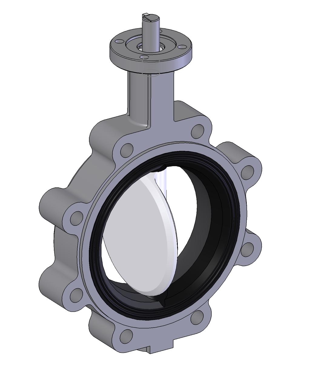
4 Description The BOS Butterfly Valve is a resilient-seated valve for general industrial applications. Lugged or wafer end connections are offered, with a choice of disc, seat, and shaft materials. Pressure and temperature ratings are shown on the valve data plate. Handling Lifting the valve improperly may damage it. Do not fasten lifting devices to the actuator, disc or through the seat opening in the body. Lift the valve with slings, chains or cables fastened around the valve body, or fastened to bolts or rods through bolt holes in the flanges Installation Refer to the valve installation drawing for dimensional information. Installing the valve in the wrong location may cause excessive dynamic torque and damage the valve. Install the valve at least 8 pipe diameters downstream from the nearest pump or elbow. Pipeline flow may be in either direction through the valve. For optimum performance, install the valve with the higher pressure on the seat side of the valve (flat side of disc). If possible, install the valve with the shaft horizontal to provide a self-cleaning action on the seat. Use pipeline flanges that conform to ASME/ANSI B16.1 Class 125 or ASME/ANSI B16.5 Class 150. Mount wafer body valves to the pipeline flanges with either bolts or studs that extend through both flanges: Mount lugged body valves to the pipeline flanges with bolts only. Studs are not recommended. Lifting a larger size valve incorrectly can damage it. Do not fasten lifting devices to the actuator or disc, or through the seat opening in the body. Lift the valve with slings fastened around the valve body, or attach them to bolts or rods run through holes for the pipeline flanges. 1. If the valve has been ordered without an actuator, mount the actuator on the valve. For a DeZURIK actuator, refer to the Actuator Instructions. For an actuator other than DeZURIK, the dimensional requirements for the actuator interface are shown on the Installation Drawing for the valve. 2. Before installation, remove all foreign material such as weld spatter, oil, grease, and dirt from the valve, flanges, and pipeline. 3. Open the valve, and clean the seat and the sealing edge of the disc. 4. Place the valve in the pipeline with the valve closed. Handle the valve carefully so that the integral flange sealing surfaces are not scratched or damaged. Do not use gaskets between valve and mating flanges. 5. Ensure that the valve, the pipeline and the mating connections are aligned and centered before tightening the pipeline bolts. 6. Open the valve slowly to ensure that there is adequate clearance between the open disc and the pipeline. 7. Tighten the bolts evenly, in a crisscross pattern. D10459 Page 4 October 2013
5 Operation DeZURIK Clockwise rotation of the valve shaft closes the disc into the seat. The valve is fully closed when the flat side of the disc is parallel with the flange sealing surface on the body. The valve is fully open when the disc is 90 counterclockwise from the closed position. A machined flat on the top of the valve shaft corresponds to the flat side of the disc. The machined flat may be used to determine the approximate position of the disc when the disc is not visible. The valve actuator is connected to the valve shaft, and positions the disc at the open, closed, or intermediate positions. The adjustable open and closed position stops in the valve actuator are set to match the open and closed positions of the valve. Refer to the Actuator Instructions for actuator stop adjustment information. Lubrication The valve is lubricated at the factory, and does not require routine lubrication. Refer to the actuator instructions for actuator lubrication requirements. If the valve is disassembled, apply a paint-like coating of the below lubricant to the following surfaces (see Figure 1 for each area listed below): A. The two shaft holes and lip seals in the seat. B. The area of the seat adjacent to the two shaft holes. C. The upper shaft seal (A6). D. The inside diameters of the four shaft bearings (A4, A5 & A12). E. The chamfer on the bottom end of the shaft (A3). F. The spline of the shaft (A3). G. The spline of the disc (A2). H. The area of shaft just above the spline. For oxygen service valves, use Hooker Fluorolube GR-362 (no substitutes are allowed). For other valves with EPDM, NBR or FKM seat material, use Dow Corning 111 (no substitutes are allowed). October 2013 Page 5 D10459
6 Lubrication (Continued) Figure 1 Areas to Lubricate D10459 Page 6 October 2013
7 Parts Identification Figure 2 Parts Identification October 2013 Page 7 D10459
8 Removing Valve from Pipeline Follow the steps below to remove the valve from the pipeline. Loosening the flange bolts on a pressurized valve can allow the valve to suddenly shift position and release uncontrolled pipeline fluid. To avoid personal injury or pipeline damage, relieve the pressure in the pipeline before loosening the pipeline flange bolts. 1. Relieve pressure in the pipeline, and drain the pipeline. 2. Close the valve. Moving parts from accidental operation of a powered actuator can cause personal injury or equipment damage. Disconnect and lock out power to actuator before servicing. 3. If the actuator is powered, disconnect and lock out the pneumatic, hydraulic, or electrical power to prevent accidental operation. 4. Support the valve, remove the flange bolting, and remove the valve from the pipeline. Refer to the lifting requirements in the Installation section. Disassembling the Valve Refer to Figure 2 for parts identification. 1. Remove the valve from the pipeline as described in the Removing Valve From Pipeline section. 2. Remove the actuator as described in the Actuator Instructions. 3. Remove the pipe plug (A11) from threaded lower end of body (A1). 4. Remove the retaining ring (A9) from the groove in the upper end of body (A1). 5. Remove the washer (A8). 6. To remove the shaft (A3) from the disc (A2), tap the lower end of the shaft (A3) towards the upper end of the body (A1) and remove the shaft from the body. 7. Remove the disc (A2) from the body (A1). 8. Remove the two upper bearings (A5) and o-ring (A6) from the upper body shaft bore. D10459 Page 8 October 2013
9 Reassembling the Valve DeZURIK Clean and inspect all parts, and replace worn parts. Refer to Figure 2 for parts identification. Lubricate the valve as noted in the Lubrication section. 1. Place the two upper bearings (A5) and o-ring (A6) seal in the upper body shaft bore. 2. Assemble the disc (A2) in the body (A1) with the spline towards the bottom of the body aligning the disc shaft bore with the body shaft bores. 3. Assemble the shaft (A3) into the body (A1) and disc (A2) shaft bores until the spline in the shaft just contacts the disc spline (slight resistance will be felt between shaft and disc). Note: If the retaining ring (A7) in the shaft (A3) is damaged, replace the retaining ring. Verify that the new retaining ring is completely seated in the shaft groove before installing the shaft. 4. Position the flat on shaft (A3) so that it is parallel to and on the same side of the flat on the disc (A2). See Figure 3 for disc/shaft alignment. Then slide and fully engage the shaft spline with the disc spline (shaft will bottom out in disc bore when fully engaged). Figure 3 Disc/Shaft Alignment October 2013 Page 9 D10459
10 Reassembling the Valve (Continued) 5. Assemble the thrust washer (A8) into the upper body shaft bore and against the snap ring (A7) in the shaft (A3). 6. Assemble the retaining ring (A9) into the retaining ring groove located in the upper body bore. Note: Verify that the retaining ring is completely seated in the retaining ring body groove. 7. Assemble the pipe plug (A11) into the threaded lower body. 8. Mount the actuator on the valve as described in the Actuator instructions. 9. Install the valve as described in the Installation section. If the actuator is a powered actuator, re-connect the power and other connections. Troubleshooting Condition Possible Cause Corrective Action Valve does not fully close. Valve leaks when closed. Valve does not fully open. Opening or closing torque is excessive. Valve leaks between body and pipeline flanges. Media leaks between actuator and top of valve Object is wedged between disc and seat Closed position stop is not adjusted correctly. Disc-to-shaft connection has failed. Closed position stop is not adjusted correctly. Seat is worn or damaged. Sealing edge of disc is worn or damaged. Open position stop is not adjusted correctly. Disc-to-shaft connection has failed. Bearings, shaft, disc or seat are dirty or worn Shaft is bent. Valve flange seal is damaged. Flange bolts are tightened incorrectly. Flange gaskets were used between valve and pipeline flanges. O-ring (A6) leaking at top of shaft. Open valve, and allow flow to remove object Adjust closed stop. Replace shaft and/or disc. Adjust closed stop. Replace valve or valve body. Replace valve or valve body. Adjust open stop. Replace shaft and/or disc. Clean or replace dirty or worn components. Replace shaft. Replace valve or valve body. Tighten the flange bolts evenly, in a crisscross pattern. Remove flange gaskets. Inspect and replace O-ring (A6). D10459 Page 10 October 2013
 months from date of shipment from factory, against defective workmanship and material, but only if properly")
11 Guarantee Products, auxiliaries and parts thereof of DeZURIK, Inc. manufacture are warranted to the original purchaser for a period of twenty-four (24) months from date of shipment from factory, against defective workmanship and material, but only if properly installed, operated and serviced in accordance with DeZURIK, Inc. recommendations. Repair or replacement, at our option, for items of DeZURIK, Inc. manufacture will be made free of charge, (FOB) our facility with removal, transportation and installation at your cost, if proved to be defective within such time, and this is your sole remedy with respect to such products. Equipment or parts manufactured by others but furnished by DeZURIK, Inc. will be repaired or replaced, but only to the extent provided in and honored by the original manufacturers warranty to DeZURIK, Inc., in each case subject to the limitations contained therein. No claim for transportation, labor or special or consequential damages or any other loss, cost or damage shall be allowed. You shall be solely responsible for determining suitability for use and in no event shall DeZURIK, Inc. be liable in this respect. DeZURIK, Inc. does not guarantee resistance to corrosion, erosion, abrasion or other sources of failure, nor does DeZURIK, Inc. guarantee a minimum length of service. Your failure to give written notice to us of any alleged defect under this warranty within twenty (20) days of its discovery, or attempts by someone other than DeZURIK, Inc. or its authorized representatives to remedy the alleged defects therein, or failure to return product or parts for repair or replacement as herein provided, or failure to install and operate said products and parts according to instructions furnished by DeZURIK, Inc., or misuse, modification, abuse or alteration of such product, accident, fire, flood or other Act of God, or failure to pay entire contract price when due shall be a waiver by you of all rights under this warranty. The foregoing guarantee shall be null and void if, after shipment from our factory, the item is modified in any way or a component of another manufacturer, such as but not limited to, an actuator is attached to the item by anyone other than DeZURIK, Inc. Factory Service personnel. All orders accepted shall be deemed accepted subject to this limited warranty, which shall be exclusive of any other or previous Warranty, and this shall be the only effective guarantee or warranty binding on DeZURIK, Inc., despite anything to the contrary contained in the purchase order or represented by any agent or employee of DeZURIK, Inc., in writing or otherwise, notwithstanding, including but not limited to implied warranties. THE FOREGOING REPAIR AND REPLACEMENT OBLIGATIONS ARE IN LIEU OF ALL OTHER WARRANTIES, OBLIGATIONS AND LIABILITIES, INCLUDING ALL WARRANTIES OF FITNESS FOR A PARTICULAR PURPOSE OR OF MERCHANTABILITY OR OTHERWISE, EXPRESSED OR IMPLIED IN FACT OR BY LAW, AND STATE DEZURIK, INC. S ENTIRE AND EXCLUSIVE LIABILITY AND YOUR EXCLUSIVE REMEDY FOR ANY CLAIM IN CONNECTION WITH THE SALE AND FURNISHING OF SERVICES, GOODS OR PARTS, THEIR DESIGN, SUITABILITY FOR USE, INSTALLATION OR OPERATIONS. Limitation of liability LIMITATION OF LIABILITY: IN NO EVENT SHALL DEZURIK, INC. BE LIABLE FOR ANY DIRECT, INDIRECT, SPECIAL OR CONSEQUENTIAL DAMAGES WHATSOEVER, AND DEZURIK, INC. S LIABILITY, UNDER NO CIRCUMSTANCES, WILL EXCEED THE CONTRACT PRICE FOR THE GOODS AND/OR SERVICES FOR WHICH LIABILITY IS CLAIMED. ANY ACTION BY YOU FOR BREACH OF CONTRACT MUST BE COMMENCED WITHIN 12 MONTHS AFTER THE DATE OF SALE. Sales and Service For information about our worldwide locations, approvals, certifications and local representative: Web site: info@dezurik.com 250 Riverside Ave. N., Sartell, MN Phone: Fax: DeZURIK, Inc. reserves the right to incorporate our latest design and material changes without notice or obligation. Design features, materials of construction and dimensional data, as described in this manual, are provided for your information only and should not be relied upon unless confirmed in writing by DeZURIK, Inc. Certified drawings are available upon request. Printed in U.S.A.
APCO CRF-100A RUBBER FLAPPER SWING CHECK VALVES
 APCO CRF-100A RUBBER FLAPPER SWING CHECK VALVES Instruction D12043 June 2016 DeZURIK Instructions These instructions provide installation, operation and maintenance information for APCO CRF-100A Rubber
DeZURIK 24 and Larger BHP High Performance Butterfly Valves WITH (FB) FYRE-BLOCK SEAT
 FYRE-BLOCK SEAT") 24 and Larger BHP High Performance Butterfly Valves WITH (FB) FYRE-BLOCK SEAT Instruction D10497 April 2015 BHP High Performance Butterfly Valves (S2, S3, S5, AA, HC, ML, T2 & T5 Shafts) Instructions These
24 and Larger BHP High Performance Butterfly Valves WITH (FB) FYRE-BLOCK SEAT Instruction D10497 April 2015 BHP High Performance Butterfly Valves (S2, S3, S5, AA, HC, ML, T2 & T5 Shafts) Instructions These
DeZURIK 2-24 (50-600mm) KGN-RSB BI-DIRECTIONAL CAST STAINLESS STEEL KNIFE GATE VALVES
 KGN-RSB BI-DIRECTIONAL CAST STAINLESS STEEL KNIFE GATE VALVES") 2-24 (50-600mm) KGN-RSB BI-DIRECTIONAL CAST STAINLESS STEEL KNIFE GATE VALVES Instruction D11023 October 2016 Instructions These instructions provide information about KGN-RSB Knife Gate Valves. They are
2-24 (50-600mm) KGN-RSB BI-DIRECTIONAL CAST STAINLESS STEEL KNIFE GATE VALVES Instruction D11023 October 2016 Instructions These instructions provide information about KGN-RSB Knife Gate Valves. They are
DeZURIK KUL KNIFE GATE VALVES
 KUL KNIFE GATE VALVES Instruction D11025 September 2013 Instructions These instructions are intended for personnel who are responsible for the installation, operation and maintenance of your KUL knife
DeZURIK 24" THRU 36" RESILIENT BUTTERFLY VALVES
 24" THRU 36" RESILIENT BUTTERFLY VALVES Instruction D10348 April 2015 Instructions These instructions provide information about DeZURIK 24" thru 36" Resilient Butterfly Valves. They are for use by personnel
APCO ASR-400/450 SEWAGE AIR RELEASE VALVES
 APCO ASR-400/450 SEWAGE AIR RELEASE VALVES Instruction D12005 December 2012 Instructions These instructions provide installation, operation and maintenance information for the APCO ASR- 400/450 Sewage
APCO CSV-1600 SURGE CHECK VALVE
 APCO CSV-1600 SURGE CHECK VALVE Instruction D12022 January 2013 Instructions These instructions provide installation, operation and maintenance information for APCO CSV-1600 Surge Check Valves. They are
DeZURIK AFR3 Filter Regulator Used on Pneumatic Cylinder Actuators
 AFR3 Filter Regulator Used on Pneumatic Cylinder Actuators Instructions D11033 August 2013 Instructions These instructions provide information about AFR3 Filter Regulators. They are for use by personnel
APCO CVS-6000 CONVERTIBLE SWING CHECK VALVES
 APCO CVS-6000 CONVERTIBLE SWING CHECK VALVES Instruction D12009 December 2012 Instructions These instructions provide installation, operation and maintenance information for APCO CVS-6000 Convertible Swing
DeZURIK 2-24 (50-600mm) KGC ES or HD KNIFE GATE VALVES
 KGC ES or HD KNIFE GATE VALVES") 2-24 (50-600mm) KGC ES or HD KNIFE GATE VALVES Instruction D10411 March 2017 Instructions These instructions are intended for personnel who are responsible for the installation, operation and maintenance
2-24 (50-600mm) KGC ES or HD KNIFE GATE VALVES Instruction D10411 March 2017 Instructions These instructions are intended for personnel who are responsible for the installation, operation and maintenance
DeZURIK KGC-MD KNIFE GATE VALVES
 KGC-MD KNIFE GATE VALVES Instruction D11032 February 2018 Instructions These instructions are intended for personnel who are responsible for the installation, operation and maintenance of your KGC-MD knife
DeZURIK PEC ECCENTRIC VALVES
 3650-7200 PEC ECCENTRIC VALVES Instruction D10019 April 2015 Instructions These instructions provide information about PEC Eccentric Valves. They are for use by personnel who are responsible for installation,
DeZURIK VPB V-PORT BALL VALVES
 VPB V-PORT BALL VALVES Instruction D10324 June 2017 Instructions These instructions provide information about. They are for use by personnel who are responsible for installation, operation and maintenance
DeZURIK KSV CL150 & CL300 BONNETLESS KNIFE GATE VALVES
 KSV CL150 & CL300 BONNETLESS KNIFE GATE VALVES Instruction D11021 October 2016 Instructions These instructions provide information about DeZURIK KSV CL150 & CL300 knife gate valves. They are intended for
DeZURIK 2-16" PTW & PFW TAPERED PLUG VALVES
 2-16" PTW & PFW TAPERED PLUG VALVES Instruction D10188 April 2015 Instructions These instructions provide information about Tapered Plug Valves. They are for use by personnel who are responsible for installation,
Nor East. Instructions Safety Messages. Inspection. Parts. DeZURIK Service. Type 05 Pneumatic Actuator Used With Globe Valves
 Instructions Safety Messages These instructions are intended for personnel who are responsible for installation, operation and maintenance of your DeZURIK Actuator. All safety messages in the instructions
DeZURIK BHP HIGH PERFORMANCE BUTTERFLY VALVE
 BHP HIGH PERFORMANCE BUTTERFLY VALVE Instruction D10503 November 2015 Instructions These instructions provide information about the DeZURIK High Performance Butterfly Valve. They are for use by personnel
Recommended spare parts are listed on the assembly drawing. These parts should be stocked to minimize downtime.
 Instruction D10411 July 2018 Instructions These instructions are intended for personnel who are responsible for the installation, operation and maintenance of your KGC knife gate valve, including models
APCO SRG-6500 SURGE RELIEF GLOBE VALVES
 APCO SRG-6500 SURGE RELIEF GLOBE VALVES Instruction D12020 December 2012 Instructions These instructions provide installation, operation and maintenance information for APCO SRG-6500 Surge Relief Globe
APCO ACS-1200/1700 COMBINATION SLOW CLOSING AIR/VACUUM VALVE
 APCO ACS-1200/1700 COMBINATION SLOW CLOSING AIR/VACUUM VALVE Instruction D12025 December 2012 Instructions These instructions provide installation, operation and maintenance information for APCO ACS- 1200/1700
APCO CVS-250/250A SWING CHECK VALVES
 APCO CVS-250/250A SWING CHECK VALVES Instruction D12003 September 2015 Instructions These instructions provide installation, operation and maintenance information for APCO CVS- 250/250A Swing Check Valves.
Nor East. Instructions. Safety Messages. Inspection. Parts Nor East Controls. Service. Type 05 Air-O-Motor Actuator Used With Globe Valves
 Instructions Safety Messages These instructions are intended for personnel who are responsible for installation, operation and maintenance of your Nor East Controls Actuator. All safety messages in the
DeZURIK " PEC ECCENTRIC VALVES
 20.5 36" PEC ECCENTRIC VALVES Instruction D10032 April 2015 20.5-36" PEC Eccentric Valves Instructions These instructions provide information about PEC Eccentric Valves. They are for use by personnel who
CSA products for waste water. Combination air valve. Mod. SCF 2
 CSA products for waste water Combination air valve Mod. SCF 2 Instructions These instructions provide installation, operation and maintenance information for CSA Mod. SCF-2 series waste water air valve.
CSA products for treated water. Water Combination air valve. Mod. FOX 3F RFP and Lynx 3F RFP
 CSA products for treated water Water Combination air valve Mod. FOX 3F RFP and Lynx 3F RFP Instructions These instructions provide installation, operation and maintenance information for CSA water combination
DeZURIK " BAW AWWA BUTTERFLY VALVES WITH EPOXY-RETAINED SEAT
 DeZURIK 20 144" BAW AWWA BUTTERFLY VALVES WITH EPOXY-RETAINED SEAT Instruction D10373 April 2017 Instructions These instructions provide information about the 20 (250 F2 model only) and the 24-144 BAW
CSA products for waste water. Anti water hammer combination air valve. Mod. SCF-RFP
 CSA products for waste water Anti water hammer combination air valve Mod. SCF-RFP Instructions These instructions provide installation, operation and maintenance information for CSA Mod. SCF-RFP series
DeZURIK DR 125 ROTARY DIAPHRAGM ACTUATOR
 DR 125 ROTARY DIAPHRAGM ACTUATOR Instruction D10507 January 2017 Instructions These instructions provide information about. They are for use by personnel who are responsible for installation, operation
DeZURIK DR 40B ROTARY DIAPHRAGM ACTUATOR
 DR 40B ROTARY DIAPHRAGM ACTUATOR Instruction D10506 October 2016 Instructions These instructions provide information about s. They are for use by personnel who are responsible for installation, operation
DeZURIK TEN-POSITION LEVER MANUAL ACTUATOR
 TEN-POSITION LEVER MANUAL ACTUATOR Instruction D10316 August 2012 Instructions These instructions provide information about Lever Actuators. They are for use by personnel who are responsible for installation,
DeZURIK G-SERIES MANUAL ACTUATOR USED ON BOS BUTTERFLY VALVES
 G-SERIES MANUAL ACTUATOR USED ON BOS BUTTERFLY VALVES Instruction D10465 August 2012 Instructions These instructions provide information about G-Series Manual Actuators. They are for use by personnel who
Nor East /9500 Series Double Seated Cage Valves. Instructions. Safety Messages. Inspection. Parts. Nor East Controls Service
 1 12 9200/9500 Series Double Seated Cage Valves Instructions Safety Messages These instructions are intended for personnel who are responsible for installation, operation and maintenance of your Nor East
DeZURIK PNEUMATIC CYLINDER OPERATOR FOR G-SERIES ACTUATORS
 PNEUMATIC CYLINDER OPERATOR FOR G-SERIES ACTUATORS Instruction D10047 March 2017 Instructions These instructions provide information about pneumatic cylinder operators. They are for use by personnel who
VSI, LLC SERIES 2100 RESILIENT SEATED BUTTERFLY VALVES INSTALLATION, OPERATION AND MAINTENANCE MANUAL
 VSI SERIES 2100 RESILIENT SEATED BUTTERFLY VALVES VSI, LLC. 2-0 SERIES 2100 RESILIENT SEATED BUTTERFLY VALVES INSTALLATION, OPERATION AND MAINTENANCE MANUAL Publication: V2100- August 2016 TABLE OF CONTENTS
APCO CVS-6000 SWING CHECK VALVES
 APCO CVS-6000 SWING CHECK VALVES Instruction D12006 December 2012 Instructions These instructions provide installation, operation and maintenance information for APCO CVS-6000 Swing Check Valves. They
DeZURIK R1 POWERRAC ACTUATOR ON 1/2-3" PEC ECCENTRIC VALVES
 R1 POWERRAC ACTUATOR ON 1/2-3" PEC ECCENTRIC VALVES Instruction D10381 August 2012 Instructions These instructions provide information about the R1 PowerRac actuator. They are for use by personnel who
DeZURIK CYLINDER OPERATED T-SERIES ACTUATOR
 CYLINDER OPERATED T-SERIES ACTUATOR Instruction D10135 August 2012 Instructions These instructions provide information about s. They are for use by personnel who are responsible for installation, operation
582 Series. Instruction Manual. Two-Door Wafer Check Valve N-582 (R-08/2016)
") 582 Series Two-Door Wafer Check Valve Instruction Manual N-582 (R-08/2016) Instructions These instructions provide installation, operation and maintenance information for Cla-Val 582 Series. They are for
582 Series Two-Door Wafer Check Valve Instruction Manual N-582 (R-08/2016) Instructions These instructions provide installation, operation and maintenance information for Cla-Val 582 Series. They are for
DeZURIK R1 AND R2 POWERRAC ACTUATORS
 R1 AND R2 POWERRAC ACTUATORS Instruction D10268 July 2016 Instructions These instructions provide installation, operation, and maintenance information for R1 AND R2 POWERRAC Actuators. They include procedures
DeZURIK LA-SERIES MANUAL & ELECTRIC ACTUATORS
 LA-SERIES MANUAL & ELECTRIC ACTUATORS Instruction D10308 August 2012 Instructions These instructions provide information about LA-Series Actuators. They are for use by personnel who are responsible for
APCO SRA-3000A SURGE RELIEF ANGLE VALVES
 APCO SRA-3000A SURGE RELIEF ANGLE VALVES Instruction D12037 July 2016 Instructions These instructions provide installation, operation and maintenance information for APCO SRA-3000A Surge Relief Angle Valves.
CSA products for treated water. Equilibrium float valve. Mod. Athena
 CSA products for treated water Equilibrium float valve Mod. Athena Rev. 1 7/2014 Introduction This manual will provide you with the information to properly install and maintain CSA float valves ATHENA.
DeZURIK SPRING RETURN CYLINDER OPERATOR FOR G-SERIES ACTUATORS USED ON PEF 100% PORT ECCENTRIC VALVES
 SPRING RETURN CYLINDER OPERATOR FOR G-SERIES ACTUATORS USED ON PEF 100% PORT ECCENTRIC VALVES Instruction D10466 December 2012 Instructions These instructions provide information about s. They are for
DeZURIK M-SERIES MANUAL ACTUATOR
 M-SERIES MANUAL ACTUATOR Instruction D10287 February 2017 Instructions These instructions provide information about Manual s. They are for use by personnel who are responsible for installation, operation
DeZURIK MANUAL G-SERIES ACTUATOR USED ON PEF 100% PORT PLUG VALVES
 MANUAL G-SERIES ACTUATOR USED ON PEF 100% PORT PLUG VALVES Instruction D10456 August 2012 Manual G-Series Actuator used on Instructions These instructions provide information about Manual G-Series Actuators
DeZURIK MANUAL G-SERIES ACTUATORS USED ON PEC ECCENTRIC VALVES
 MANUAL G-SERIES ACTUATORS USED ON PEC ECCENTRIC VALVES Instruction D10063 August 2012 Instructions These instructions provide information about Manual G-Series Actuators. They are for use by personnel
DeZURIK MODELS P41, P41D AND P42 PMV POSITIONERS
 MODELS P41, P41D AND P42 PMV POSITIONERS Instruction D10112 August 2012 Instructions These instructions provide information about. They are for use by personnel who are responsible for installation, operation
SERIES RSR PRESSURE RELIEF VALVE
 SERIES RSR PRESSURE RELIEF VALVE Installation, Operation and Maintenance Manual The Red Valve Series RSR Pressure Relief Valve is a bi-directional valve designed for tough slurry applications. The elastomer
PO Box 411 Berwick PA VALV
 I N S T A L L A T I O N A N D M A I N T E N A N C E F O R S E R I E S 4 7 K - F L O B U T T E R F L Y V A L V E S PO Box 411 Berwick PA 18603 800-247-VALV www.crispinvalve.com Product Introduction -- K-FLO
AVK SERIES 41 SWING CHECK VALVE FIELD MAINTENANCE AND INSTRUCTION MANUAL FOR SWING CHECK VALVES 3" - 12"
 AMERICAN AVK COMPANY AVK SERIES 41 SWING CHECK VALVE FIELD MAINTENANCE AND INSTRUCTION MANUAL FOR SWING CHECK VALVES 3" - 12" TABLE OF CONTENTS EXPLODED ASSEMBLY / PARTS LIST INTRODUCTION / DESCRIPTION
MetroPrime 22MPC Self-Priming Centrifugal Pump
 Page 1 of 6 prevent priming or reduce pump capacity. OPERATION The 22 MPC-Metropolitan Pump is a self-priming centrifugal pump and only requires priming prior to its initial start. The pump will retain
2" - 24" OS Series Butterfly Valves. Operation and Maintenance Manual. Job Name: Contractor: Date:
 s Operation and Maintenance Manual Job Name: Contractor: Date: Document #: IOM Revision Date: 10/2/2016 SAFETY MESSAGES All safety messages in the instructions are flagged with an exclamation symbol and
AVK SERIES 41 SWING CHECK VALVE FIELD MAINTENANCE AND INSTRUCTION MANUAL FOR SWING CHECK VALVES 3" - 12"
 AMERICAN AVK COMPANY AVK SERIES 41 SWING CHECK VALVE FIELD MAINTENANCE AND INSTRUCTION MANUAL FOR SWING CHECK VALVES 3" - 12" TABLE OF CONTENTS EXPLODED ASSEMBLY / PARTS LIST INTRODUCTION / DESCRIPTION
DAP-625S and DAP-875S
 AIR CHAMP PRODUCTS DAP-625S and DAP-875S (i) FORM NO. L-20078-B-0501 In accordance with Nexen s established policy of constant product improvement, the specifications contained in this manual are subject
Elgin Hydraulic Clutch-Brake ECB-240, Product Number FORM NO. L F FORM NO. L F-0704
 Elgin Hydraulic Clutch-Brake ECB-20, Product Number 96225 FORM NO. L-20283-F-070 1 FORM NO. L-20283-F-070 In accordance with Nexen s established policy of constant product improvement, the specifications
Spring-Engaged/Hydraulically-Released BD Caliper Brake. (i) MTY (81) QRO (442) MEX (55)
 MTY (81) QRO (442) MEX (55)") Spring-Engaged/Hydraulically-Released BD Caliper Brake (i) FORM NO. L-07-E-0300 In accordance with Nexen s established policy of constant product improvement, the specifications contained in this manual
Spring-Engaged/Hydraulically-Released BD Caliper Brake (i) FORM NO. L-07-E-0300 In accordance with Nexen s established policy of constant product improvement, the specifications contained in this manual
Series 820 AWWA Butterfly Valves
 Series 820 AWWA Butterfly Valves Installation, Operation and Maintenance September 2015 SP-820-IOM-0915A Series 820 AWWA Butterfly Valves Installation, Operation and Maintenance Contents General.....3
INSTALLATION, OPERATION AND MAINTENANCE FOR SERIES 500 K-FLO BUTTERFLY VALVES
 INSTALLATION, OPERATION AND MAINTENANCE FOR SERIES 500 K-FLO BUTTERFLY VALVES PO Box 411 Berwick PA 18603 800-247-VALV www.crispinvalve.com Product Introduction -- K-FLO Series 500: 3 --20 Introduction
BC Brake Caliper. (i) MEX (55) QRO (442) MTY (81) DIST. AUTORIZADO
 MEX (55) QRO (442) MTY (81) DIST. AUTORIZADO") MEX (55) 5 6 QRO (44) 95 7 60 MTY () 54 0 BC Brake Caliper (i) FORM NO. L-0066-B-040 In accordance with Nexen s established policy of constant product improvement, the specifications contained in this
MEX (55) 5 6 QRO (44) 95 7 60 MTY () 54 0 BC Brake Caliper (i) FORM NO. L-0066-B-040 In accordance with Nexen s established policy of constant product improvement, the specifications contained in this
MANUAL ACTUATOR FOR KNIFE GATE VALVES
 MANUAL ACTUATOR FOR KNIFE GATE VALVES Instruction D10079 November 2013 Instructions These instructions are intended for personnel who are responsible for the installation, operation and maintenance of
VSI INDUSTRIAL BALL VALVES SERIES 7100 SERIES 8100 SERIES 7200 SERIES 8300 SERIES 7400 SERIES 8400 SERIES 8000 SERIES 8500
 VSI INDUSTRIAL BALL BUTTERFLY VALVES VSI INDUSTRIAL BALL VALVES SERIES 7100 SERIES 8100 SERIES 7200 SERIES 8300 SERIES 7400 SERIES 8400 SERIES 8000 SERIES 8500 INSTALLATION, OPERATION AND MAINTENANCE MANUAL
Straight-Bore Clutch LSCC-32, 44, 54
 Straight-Bore Clutch LSCC-32, 44, 54 1 In accordance with Nexen s established policy of constant product improvement, the specifications contained in this manual are subject to change without notice. Technical
24-48 HP250II Butterfly Valve. Operation and Maintenance Manual. Job Name: Contractor: Date: Document #: 2448HP250OOOM Revision Date: 1/10/11
 24-48 HP250II Butterfly Valve Operation and Maintenance Manual Job Name: Contractor: Date: Document #: 2448HP250OOOM Revision Date: 1/10/11 SAFETY MESSAGES All safety messages in the instructions are flagged
GA-160 Gas Amplifier
 GA-160 Gas Amplifier INSTALLATION, OPERATION & MAINTENANCE MANUAL INTERFACE DEVICES, INC. 230 Depot Road, Milford, CT 06460 Ph: (203) 878-4648, Fx: (203) 882-0885, E-mail: info@interfacedevices.com www.interfacedevices.com
PMV P36C AND P41C POSITIONERS ACTUATORS
 PMV P36C AND P41C POSITIONERS USED WITH DeZURIK PNEUMATIC ACTUATORS Instruction D10327 August 2012 Instructions These instructions provide information about Models P36C and P41C PMV Positioners. They are
Single-Position Detent Clutch DC Series. (i) MTY (81) MEX (55) QRO (442)
 MTY (81) MEX (55) QRO (442)") Single-Position Detent Clutch DC Series (i) FORM NO. L-2017-A-001 In accordance with Nexen s established policy of constant product improvement, the specifications contained in this manual are subject
Single-Position Detent Clutch DC Series (i) FORM NO. L-2017-A-001 In accordance with Nexen s established policy of constant product improvement, the specifications contained in this manual are subject
CONTENTS. VIKING PUMP, INC. A Unit of IDEX Corporation Cedar Falls, IA USA SECTION TSM 710.1
 TECHNICAL SERVICE MANUAL industrial heavy duty motor speed pumps SERIES 4076 AND 4176 SIZES hle, ate and ale SECTION TSM 710.1 PAGE 1 of 8 ISSUE B CONTENTS Introduction....................... 1 Safety
JET METER INSTRUCTIONS
 UNPACKING Please open and inspect your package upon receipt. Your package was packed with great care and all the necessary packing materials to arrive to you undamaged. If you do find an item that is broken
Through-Shaft Clutch-Brake LSCB-32HT, LSCB-32HT, LSCB-44, LSCB-44HT, LSCB-54HT FORM NO. L D-0606 MEX (55) QRO (442)
 QRO (442)") Through-Shaft Clutch-Brake LSCB-HT, LSCB-HT, LSCB-, LSCB-HT, LSCB-5HT In accordance with Nexen s established policy of constant product improvement, the specifications contained in this manual are subject
Through-Shaft Clutch-Brake LSCB-HT, LSCB-HT, LSCB-, LSCB-HT, LSCB-5HT In accordance with Nexen s established policy of constant product improvement, the specifications contained in this manual are subject
SLURRY KNIFE GATE VALVE
 SERIES D FLEXGATE SLURRY KNIFE GATE VALVE Installation, Operation and Maintenance Manual The Red Valve Series D Flexgate Slurry Knife Gate Valve is a 100% full bore, truly bi-directional valve designed
3-20 2FII & Groundhog Bonded Seat Butterfly Valve. Operation and Maintenance Manual. Job Name: Contractor: Date:
 3-20 2FII & Groundhog Bonded Seat Butterfly Valve Operation and Maintenance Manual Job Name: Contractor: Date: Document #:3202FIIGD Revision Date: 1/10/11 SAFETY MESSAGES All safety messages in the instructions
A Member of the. Integrated Metering Technologies
 I n s t a l l a t i o n M a n u a l A Member of the Integrated Metering Technologies 1.0 General and safety Do not install, operate or maintain this flow meter without reading, understanding and followingthe
Air Chain Hoist. Follow all instructions and warnings for. Capacities. 250 lbs (113 kg) 300 lbs (136 kg) 500 lbs (226 kg) 600 lbs (272 kg)
 300 lbs (136 kg) 500 lbs (226 kg) 600 lbs (272 kg)") Air Chain Hoist Operating, Maintenance & Parts Manual Follow all instructions and warnings for inspecting, maintaining and operating this hoist. The use of any hoist presents some risk of personal injury
Air Chain Hoist Operating, Maintenance & Parts Manual Follow all instructions and warnings for inspecting, maintaining and operating this hoist. The use of any hoist presents some risk of personal injury
Tissue Master. User Manual
 Tissue Master User Manual This page left blank intentionally This manual is a guide for the use of the Omni International Tissue Master and accessories. Data herein has been verified and validated. It
MEX (55) QRO (442) Web Controls
 QRO (442) Web Controls") Web Controls SINGLE AND DUAL ROTOR TENSION CONTROL BRAKES MODELS:,,,, AND INSTALLATION, OPERATION, AND MAINTENANCE INSTRUCTIONS Read this manual carefully, making full use of its explanations and instructions.
Web Controls SINGLE AND DUAL ROTOR TENSION CONTROL BRAKES MODELS:,,,, AND INSTALLATION, OPERATION, AND MAINTENANCE INSTRUCTIONS Read this manual carefully, making full use of its explanations and instructions.
TONS. Before each shift: Before operating: Before initial operation of hoist:
 LEVER HOIST 0.25 9 TONS Manual Notice It is the responsibility of the owner/user to install, inspect, test, maintain, and operate these lever hoists in accordance with ASME B30.21, Safety Standard for
60 Series End-Mount Brake Instructions Standard Housing
 Bulletin No. BK4655 (04/18) 60 Series End-Mount Brake Instructions Standard Housing Read carefully before attempting to assemble, install, operate or maintain the product described. Protect yourself and
SHAW-BOX INSTRUCTIONS AND PARTS LIST SHAW-BOX RIGID MOUNT I-BEAM AND PATENTED TRACK TROLLEYS (PUSH & HAND GEARED - 1/2 THRU 15 TON RATED LOADS)
") SHAW-BOX INSTRUCTIONS AND PARTS LIST SHAW-BOX RIGID MOUNT I-BEAM AND PATENTED TRACK TROLLEYS (PUSH & HAND GEARED - 1/2 THRU 15 TON RATED LOADS) GENERAL SHAW-BOX Rigid Mount I-Beam Trolleys are designed
SHAW-BOX INSTRUCTIONS AND PARTS LIST SHAW-BOX RIGID MOUNT I-BEAM AND PATENTED TRACK TROLLEYS (PUSH & HAND GEARED - 1/2 THRU 15 TON RATED LOADS) GENERAL SHAW-BOX Rigid Mount I-Beam Trolleys are designed
Stellar 4 Clutch Manual
 INSTRUCTIONS Stellar 4 Clutch Manual Thank you for choosing Tomar products; we are proud to be your manufacturer of choice. Please read this instruction sheet carefully before beginning installation, and
USER MANUAL. NEMA 48C Flange Mounted, Enclosed, Clutch Brake. FMCBE Model 500 FORM NO. L A (i)
") USER MANUAL NEMA 48C Flange Mounted, Enclosed, Clutch Brake FMCBE Model 500 (i) In accordance with Nexen s established policy of constant product improvement, the specifications contained in this manual
USER MANUAL NEMA 48C Flange Mounted, Enclosed, Clutch Brake FMCBE Model 500 (i) In accordance with Nexen s established policy of constant product improvement, the specifications contained in this manual
INTRODUCTION INSTALLATION
 INTRODUCTION INSTALLATION, OPERATION & MAINTENANCE INSTRUCTIONS This instruction manual includes installation, operation and maintenance information for the figure G73 gear operator. The figure G73 is
TECHNICAL SERVICE MANUAL
 Electronic copies of the most current TSM issue can be found on the Viking Pump website at www.vikingpump.com TECHNICAL SERVICE MANUAL industrial heavy duty motor speed pumps SERIES 4076 AND 4176 SIZES
Gauge Adapter Instruction Manual
 Instruction Manual MODELS: CF3812, CF3812E, CF3814 & CF4514 CF3812-M1_092017! This is the safety alert symbol. It is used to alert you to potential personal injury hazards. Obey all safety messages that
Metal Seated Ball Valve. Operation and Maintenance Manual. Job Name: Contractor: Date: Document #: MSBVOM Revision Date: 07/06/09
 Metal Seated Ball Valve Operation and Maintenance Manual Job Name: Contractor: Date: SAFETY MESSAGES All safety messages in the instructions are fl agged with an exclamation symbol and the word Warning.
Electric Actuator Installation, Operation & Maintenance Manual
 ICI Indelac Controls, Inc. Electric Actuator Installation, Operation & Maintenance Manual 6810 Powerline dr.-florence, Ky. 41042 - Telephone 859-727-7890, Tool free 800-662-9424 Fax. 859-727-4070, e-mail:
TITAN FLOW CONTROL, INC.
 PREFACE: This manual contains information concerning the installation, operation, and maintenance of Titan Flow Control (Titan FCI) Wafer Style, Dual Plate Check Valves. To ensure efficient and safe operation
Clevis Plunger & Base Instruction Manual
 MODELS: CED09 & CED16 SFA Companies 10939 N. Pomona Ave. Kansas City, MO 64153 Tel: 888-332-6419 - Fax: 816-448-2142 E-mail: sales@bvahydraulics.com Website: www.bvahydraulics.com CED09-M0_102017 Clevis
GA Industries, LLC 9025 Marshall Road Cranberry Township, PA USA Telephone (724) Fax (724)
 Fax (724)") INSTALLATION, OPERATION AND MAINTENANCE MANUAL LUDLOW SERIES FIGURE 350-W 3 to 30 Lever & Weight Air-Cushioned Swing Check Valves TABLE OF CONTENTS Introduction. 1 Description of Operation... 1 Receiving
INSTALLATION, OPERATION AND MAINTENANCE MANUAL LUDLOW SERIES FIGURE 350-W 3 to 30 Lever & Weight Air-Cushioned Swing Check Valves TABLE OF CONTENTS Introduction. 1 Description of Operation... 1 Receiving
Henry Pratt MDT Actuators. Operation and Maintenance Manual. Job Name: Contractor: Date: Document #MDTOM Revision Date: 1/12/11
 Henry Pratt MDT Actuators Operation and Maintenance Manual Job Name: Contractor: Date: Document #MDTOM Revision Date: 1/12/11 SAFETY MESSAGES All safety messages in the instructions are flagged with an
Single Post Caliper Brake VC500
 Single Post Caliper Brake VC500 1 In accordance with Nexen s established policy of constant product improvement, the specifications contained in this manual are subject to change without notice. Technical
FCB-450, LCB-600, MCB-800
 AIR CHAMP PRODUCTS User Manual FCB-450, LCB-600, MCB-800 Clutch-Brakes (i) In accordance with Nexen s established policy of constant product improvement, the specifications contained in this manual are
V400D VERIS Verabar (Double Rod) Installation and Maintenance Manual
 Installation and Maintenance Manual") V400D VERIS Verabar (Double Rod) Installation and Maintenance Manual 168-EN Please read and save these instructions Contents General Safety Information...3 Product Information...3 Section 1: Scope...3
V400D VERIS Verabar (Double Rod) Installation and Maintenance Manual 168-EN Please read and save these instructions Contents General Safety Information...3 Product Information...3 Section 1: Scope...3
Manifold w/ Needle Valve Instruction Manual
 MODELS: MFC2 & MFC4 Manifold w/ Needle Valve Instruction Manual SFA Companies 10939 N. Pomona Ave. Kansas City, MO 64153 Tel: 888-332-6419 - Fax: 816-448-2142 E-mail: sales@bvahydraulics.com Website: www.bvahydraulics.com
Model P-40 & Model P-25 POWER PUSHER
 Power Pusher Description INSTRUCTION MANUAL The Power Pusher provides ram capability by using the spreading power of the POWER HAWK P-16 Rescue Tool. (The Power Pusher may also be used with other spreader
CompoSeal butterfly valves, wafer style Installation & Maintenance Instructions
 Please read these instructions carefully This symbol indicates important messages and safety instructions. Intended valve use The valve is intended to be used only in applications within the pressure/temperature
Installation Guide Document N Cleanroom Mirrors Copyright 2016 Terra Universal Inc. All rights reserved. Revised November 2016
 Document N0. 1800-09 Copyright 2016 Terra Universal Inc. All rights reserved. Revised November 2016 Terra Universal, Inc. TerraUniversal.com 800 S. Raymond Ave. Fullerton, CA 92831 TEL: (714) 578-6000
SERIES 5200E Installation, Operation and Maintenance Manual
 SERIES 5200E Installation, Operation and Maintenance Manual The Red Valve Series 5200E Electrically Actuated Control Pinch Valve is a bi-directional valve designed for tough slurry applications. The elastomer
TECHNICAL SERVICE MANUAL
 TECHNICAL SERVICE MANUAL HEAVY-DUTY bracket mounted PUMPS SERIES 4193 AND 493 SIZES GG - AL SECTION TSM 154 PAGE 1 of 10 ISSUE C CONTENTS Introduction....................... 1 Special Information...................
Reach ins, Freeezers & Refrigerators Installation & Operation Manual
 Reach ins, Freeezers & Refrigerators Installation & Operation Manual BSR23 BSF23 BSR49 BSF49 BSR72 BSF72 IMPORTANT SAFETY INSTRUCTIONS (SAVE THESE INSTRUCTIONS) Visit us on the web at www.blueairinc.com
Keystone Butterfly valves ParaSeal Installation and maintenance instructions
 Before installation these instructions must be fully read and understood Please read these instructions carefully Hazard potentials: disregarding of instructions improper use of product insufficiently