OSPE Origa System Plus. Belt-Driven and Screw-Driven Modular Electric Actuators
|
|
|
- Baldric Eaton
- 5 years ago
- Views:
Transcription


1 aerospace climate control electromechanical filtration fluid & gas handling hydraulics pneumatics process control sealing & shielding OSPE Origa System Plus Belt-Driven and Screw-Driven Modular Electric ctuators


2 OSPE Series ctuators Parker Origa System Plus (OSPE) Series electric motor-driven actuator systems are field-proven worldwide. OSPE ctuator systems are completely modular to accommodate a broad range of application installation and performance requirements. Offered in belt-driven or screwdriven, horizontal and vertical configurations, OSPE ctuators are a compact, easy to install solution for new and retrofit installations. ll OSPE ctuators feature an extruded aluminium profile with double dovetail slots on three sides for direct mounting of a variety of hardware options. Developed for absolute reliability, high performance, easy handling and optimized design flexibility, OSPE ctuators meet the most critical application requirements. Belt actuators are recommended for precise movement and positioning applications with higher speeds and/or longer travel Screw actuator models are best suited for precise movement and positioning applications requiring higher load capacity and positional accuracy External guide options provide additional precision and load capacity for the most demanding applications wide range of mounting options provides great installation flexibility OSPE Series actuators are available in a range of belt-driven and screw-driven configurations that accommodate an extremely wide spectrum of load, speed and stroke requirements. OSPE Solutions for ny Condition If your installation needs to withstand harsh environmental conditions or meet a critical design specification, please contact us. We offer many non-standard design options not covered in this brochure that will help match the OSPE to your specific application requirements, including: Clean room environments Mounting of customer motors Multi-axis systems 2 Parker Hannifin Corporation Electromechanical utomation Division


3 Table of Contents pplications and Selection Overview 4 7 OSPE..BHD OSPE ctuators are used in a wide range of material handling and machine automation functions; choose the OSPE..ries with the features and performance best suited to your application requirements OSPE..BV OSPE..B Belt actuator with integrated ball bearing or roller guide for heavy duty applications Vertical belt actuator with integrated ball bearing guide and drive head Belt actuator with internal guide; most versatile belt system with a wide variety of carriage and external guide rail options for extended performance capabilities OSPE..SB/ST Ball screw or trapezoidal screw actuators with Internal plain bearing guide; available with a wide variety of carriage and external guide rail options for extended performance capabilities Options and ccessory Products External Linear Guides PowerSlide and Proline ctuator Mounting Options End Cap and Profile Mounts If you don t find exactly what you are looking for in this brochure, please contact us for information on additional OSPE configurations, other suitable Parker products, and to discuss your requirements with an application engineer. Need more information? Visit our Website... Complete up-to-date technical assistance can be found on the web at This includes all the latest information on current products, new product introductions, local assistance and support, plus a comprehensive Engineering Reference Library including: complete product catalog data, product selection Wizards, performance charts and graphs, engineering data and calculations, CD drawings, local service and support directory, on-line purchasing, application stories and videos. Parker Hannifin Corporation Electromechanical utomation Division


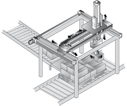
4 OSPE Series ctuators Versatile Performance for Diverse pplication Capabilities Measuring Systems Synchronized bi-parting actuation for optical curvature gauging Conveyors Simple cross-transfer actuation Material Handling Parallel actuation for a vertical life on a mechanical material handling system utomated Handling High speed pick and place movements Centering packages Self-contained mobile lift Robotics Robot traverse between workstations Vertical and horizontal transfer movements ccurate 3-axis positioning for automated filling process 4 Parker Hannifin Corporation Electromechanical utomation Division


5 Ergonomic djustment Opening and Closing Operations Simple bi-parting operation for automatic doors and guards djustment of orthopedic bed Spray Equipment Work level adjustment of workstation djustment of air dampers on ventilation system Machining Functions Precision reciprocating action Synchronized high speed bi-parting movements for spray coating operation Precise slow speed feeding in 2-axis for milling operation High speed traverse for slitting machine slicing of papers and textiles Punch press accurate feeding and positioning Intricate profile cutting movements of water jets and lasers Parker Hannifin Corporation Electromechanical utomation Division
6 OSPE Series ctuators Selection Overview t-a-glance Design Series BHD (Heavy Duty) Page 8 OSPE Belt-Driven ctuators BV (Vertical) Page 16 Bore Size Thrust Force N (lbs) 550 (124) 1070 (241) 1870 (420) 3120 (701) 650 (146) 1430 (321) Maximum Linear Speed m/s (in/s) 3 (118) Maximum cceleration m/s 2 (in/s 2 ) 50 (1969) 5 (197)* 10 (394)** 50 (1969)* 40 (1575)** 5 (197)* 10 (394)** 50 (1969)* 40 (1575)** 5 (197)* 10 (394)** 50 (1969)* 40 (1575)** 3 (118) 5 (197) 20 (787) 20 (787) Repeatability μm ±50 ±50 ±50 ±50 ±50 ±50 Maximum Order Stroke Length (1) mm (in) 5760 (227) 5700 (225) 5600 (220) 5500 ( 216) 1000 (39) 1500 (59) mbient Temperature C -30 to to to to to to 80 Protection Class IP 54 IP 54 IP 54 IP 54 IP 20 IP 20 Maximum Load N (lbs) Xpress Motor and Gearbox Options (2) Standard Carriage 1600 (360) 3000 (674)* 986 (222)** (2247)* 15000(3370)* 1348 (303)** 3704 (832)** 1600 (360) With ProLine With PowerSlide Xpress Motor Mounting Kit Xpress Gearbox Mounting Kit Xpress Mounted Gearbox w/motor Mount dapter Kit Xpress Mounted Motor Xpress Mounted Gearbox and Motor 3000 (674) Standard Carriage Tandem Carriage Bi-parting Carriage Standard Motor Mount Kit ProLine and PowerSlide External Linear Guides End Cap Mounting Profile Mounting Clevis Mounted Carriage Inversion Mounted Carriage Magnetic Position Sensors * Ball bearing guide models ** Roller guide models models (1) Longer lengths available - consult factory (2) Xpress system options are pre-assembled configurations using performance matched Parker gearboxes and motors Standard Design Options 6 Parker Hannifin Corporation Electromechanical utomation Division
7 B (Point-to-Point Versatility) Page 24 SB (Ball Screw) Page 32 OSPE Screw-Driven ctuators ST (Trapezoidal Screw) Page B 32 B 50 B 25 SB 32 SB 50 SB 25 ST 32 ST 50 ST 50 (11) 150 (34) 425 (96) 250 (56) 1100 (247) 1450 (326) 600 (135) 1300 (292) 2500 (562) 2 (79) 3 (118) 5.0 (197) 0.25 (9.8) 0.5 (19.7) 1.25 (49.2) 0.1 (3.9) 0.1 (3.9) 0.15 (5.9) 10 (394) 10 (394) 10 (394) 10 (394) 10 (394) 10 (394) 2 (79) 2 (79) 2 (79) ±50 ±50 ±50 ±50 ±50 ±50 ±500 ±500 ± (118) 5000 (197) 5000 (197) 1000 (39) 2000 (78) 3200 (126) 1000 (39) 2000 (78) 2400 (94) -30 to to to to to to to to to 70 IP 54 IP 54 IP 54 IP 54 IP 54 IP 54 IP 54 IP 54 IP (36) 300 (67) 850 (191) 500 (112) 1200 (267) 3000 (674) 500 (112) 1000 (275) 1500 (337) 986 (222) 1348 (303) 3582 (805) 986 (222) 1348 (303) 3582 (805) 986 (222) 1348 (303) 3582 (805) 1190 (267) 2300 (517) 4000 (999) 1190 (267) 2300 (517) 4000 (999) 1190 (267) 2300 (517) 4000 (999) Parker Hannifin Corporation Electromechanical utomation Division

8 OSPE..BHD Belt-Driven ctuators OSPE..BHD Belt ctuators with Integrated Ball Bearing or Roller Guide are Ideal for High Speed, Heavy Duty pplications The latest generation of high capacity actuators, the OSPE..BHD Series combines robustness, precision and high performance. The aesthetic design is easily integrated into any machine constructions by virtue of extremely adaptable mountings. Features: Integrated ball bearing guide or roller guide Complete motor and control packages Installation in any orientation Special options on request Rated IP 54 dvantages: ccurate path and position control High force output High speed operation High load capacity Easy installation Low maintenance Ideal for multi-axis applications Threaded mounting holes compatible with ProLine Series linear guides Carriage Permanent magnet for contactless position sensing Threaded mounting holes Corrosion resistant steel sealing band Steel reinforced belt Clamp shaft for zero-backlash coupling of motors and external gear arrangements High precision, hardened steel track with precision ground and calibrated bearing tracks* Steel runner block with integrated scraper system and grease nipples Slotted profile with dovetail grooves Integrated ball bearing guides (also available with integrated roller guides) 8 Parker Hannifin Corporation Electromechanical utomation Division


9 Choose from a wide range of standard options for maximum design flexibility in a pre-assembled system. Integrated Ball Bearing or Roller Bearing Guide Rail Drive Shaft Options Mounting Options Integrated ball bearing guide actuators are equipped with high precision, hardened steel track with precision ground and calibrated bearing tracks. Drive shaft with clamp shaft End cap mounting allows the actuator to be anchored at the end cap. Integrated roller guide models utilize a precision ground aluminum track; roller guides on needle bearings provide smooth operation up to 10 m/s. Drive shaft with plain shaft Profile mounting supporting long actuators or mounting the actuators on dovetail grooves. Carriage Options Standard Drive shaft with both clamp and plain shaft Magnetic Switches Mounting Rail Flexibility The dovetailed mounting rails on the actuator housing expand its function into that of a universal system carrier. Modular system components are simply clamped on. Multi-axis Systems The tandem carriage is recommended for added support of high moment loads. Magnetic switches contactless position sensing of end stop and intermediate carrier positions Simplify engineering and installation with a wide range of adapter plates and intermediate drive shafts. The bi-parting carriage is designed for perfectly synchronized bi-parting movements. Options and ccessory Product Specifications Refer to the Options and ccessories section for complete specifications on compatible motor mounts, couplings, mounting hardware, magnetic switches, etc. Parker Hannifin Corporation Electromechanical utomation Division
10 OSPE..BHD Belt-Driven ctuators Performance Data ctuator Size OSPE20BHD OSPE25BHD OSPE32BHD OSPE50BHD Integrated Guide Rail* B B R B R B R Lead Constant s lin mm Linear Speed (Max) v max m/s cceleration (Max) a max m/s Repeatability µm ± 50 ± 50 ± 50 ± 50 ± 50 ± 50 ± 50 Order Stroke (Max) mm 5,760 5,700 5,700 5,600 5,600 5,500 5,500 N 550 1,070 1,070 1,870 1,870 3,120 3,120 Thrust Force (Max) F max lbs Torque on Drive Shaft (Max) M max Nm in-lb ,567 1,567 Nm Torque No Load M 0 in-lb N 1,600 2, ,000 1,348 12,000 3,704 F Y lbs , , Load** (Max) N 1,600 3, ,000 1,348 15,000 3,704 F Z lbs , , Bending Moment Load** (Max) Zero Stroke Per Meter of Stroke Per 1 kg Moved Mass Zero Stroke Per Meter of Stroke Moved Mass of Carriage M X Nm in-lb , , M Y Nm , , in-lb 1,328 4, ,851 1,018 15,931 3,231 M Z Nm , , in-lb 1,328 4, ,391 1,018 22,127 3,231 J 0 J OS J m m 0 m OS m C kgmm 2 kgmm 2 /m kgmm 2 /kg kg kg/m kg * B = Ball Bearing Guide Rail; R = Roller Guide ** Load and bending moment based on 8000 km performance , , , , , ,678 1,738 3, ,690 1,738 3, Parker Hannifin Corporation Electromechanical utomation Division
11 Performance Data (cont.) Thrust Force (Max) F Torque on Drive Shaft (Max) M ctuator Size OSPE20BHD OSPE25BHD OSPE32BHD OSPE50BHD Integrated Guide Rail* B B R B R B R Specified Speed Specified Stroke Specified Speed Specified Stroke * B = Ball Bearing Guide Rail; R = Roller Guide <1 m/s 550 1,070 1,070 1,870 1,870 3,120 3,120 <2 m/s ,644 1,644 2,797 2,797 <3 m/s ,487 1,487 2,689 2,689 <4 m/s ,408 1,408 2,510 2,510 <5 m/s ,304 1,304 2,366 2,366 <6 m/s 691 1,251 2,312 <7 m/s 621 1,173 2,205 <8 m/s 586 1,147 2,097 <9 m/s 552 1,094 2,025 <10 m/s ,881 <1 m 550 1,070 1,070 1,870 1,870 3,120 3,120 <2 m 523 1,070 1,070 1,870 1,870 3,120 3,120 <3 m 372 1,040 1,040 1,513 1,513 2,420 2,420 <4 m ,173 1,173 1,881 1,881 <5 m ,540 1,540 <6 m ,307 <7 m ,127 <1 m/s <2 m/s <3 m/s <4 m/s <5 m/s <6 m/s <7 m/s <8 m/s <9 m/s <10 m/s <1 m <2 m <3 m <4 m <5 m <6 m <7 m Parker Hannifin Corporation Electromechanical utomation Division
12 OSPE..BHD Belt-Driven ctuators Base Unit Dimensions mm Drive Shaft Versions: Clamp Shaft Plain Shaft Clamp Shaft with Plain Shaft KP Order Stroke G x H (8x) S M ØKR EF FH CE E EC C CF KO B ØKN J Y x ZZ (10x) B FB K 10.4 KU x KJ (4x) (1) KF X (4x) ØKT ØKS V (1) Mounting holes for motor flange or external planetary gearbox. Holes are located on the opposite side to the carrier (motor mounting standard). They can also be located on the same side as the carrier (motor mounting 180 standard). ctuator Size OSPE20BHD OSPE25BHD OSPE32BHD OSPE50BHD B C E G x H M5 x 8.5 M5 x 10 M6 x 12 M6 x 12 J * K M S V X Y x ZZ M5 x 8 M6 x 8 M6 x 10 M6 x 10 CE CF EC EF FB FH KF KN KO KP KR 12 H7 16 H7 22 H7 32 H7 KS 12 h7 16 h7 22 h7 32 h7 KT KU x KJ M6 x 8 M8 x 8 M10 x 12 M12 x 19 KC KL * For OSPE50BHD with roller guide: J = Parker Hannifin Corporation Electromechanical utomation Division
13 Order Stroke Dimensions mm Standard Carriage Order Stroke (Required Travel + 2x Safety Distance*) Tandem Carriage Order Stroke (Required Travel + KM min + 2x Safety Distance*) KM min Travel Bi-Parting Carriage Order Stroke (2x Required Travel + KM min + 2x Safety Distance*) Travel KM min Travel ctuator Size OSPE20BHD OSPE25BHD OSPE32BHD OSPE50BHD KM min KM rec * Note: The mechanical end position must not be used as a mechanical end stop, thus an additional Safety Distance at both ends of travel must be incorporated into the Order Stroke. The safety distance clearance should be equivalent to the linear movement of one revolution of the drive shaft, but at least 100 mm. lso note that the use of an C motor with a VFD normally requires a larger safety clearance than that required for servo systems. For further information and design assistance, please consult the factory. Parker Hannifin Corporation Electromechanical utomation Division
14 OSPE..BHD Belt-Driven ctuators Ordering Information Select an order code from each of the numbered fields to create a complete OSPE..BHD model order number. Include hyphens and non-selective characters as shown in example below Order Number Example: OSPE P Series OSPE Origa System Plus Electromechanical 2 ctuator Bore Size mm W x 49 mm H mm W x 53 mm H mm W x 67 mm H mm W x 93 mm H 3 Drive Train 5 Belt actuator with integrated roller guide 6 Belt actuator with integrated ball bearing guide 4 Carriage 0 Standard 1 Tandem (two carriages for higher load capabilities) 2 Bi-Parting (two driven carriages for opposite movements) 5 Operating Direction Standard & Tandem (Carriage moves away from drive end) Standard & Tandem (Carriage moves toward drive end) Bi-Parting* (Carriages move toward mid-actuator) Bi-Parting* (Carriages move away from mid-actuator) * Requires Bi-Parting Carriage (order code 2 from 4 above) 6 Drive Shaft Configuration and Orientation Clamp shaft (opposite carriage 02 side) (see Clamp Shaft with Xpress Clamp Mounted Gearbox options below) Clamp Clamp shaft (same side as carriage) 04 (see Clamp Shaft with Xpress Mounted Gearbox options below) Plain Clamp shaft* (opposite carriage 03 side) with plain shaft for use with intermediate drive shaft for parallel Clamp actuator system Clamp Clamp shaft* (same side as 05 carriage) with plain shaft for use with intermediate drive shaft for Plain parallel actuator system Plain shaft idler unit** (opposite 0 carriage side) for parallel actuator Plain system Plain Plain shaft idler unit** (same side 0B as carriage) for parallel actuator system * vailable with Xpress Gearbox Mounting Kit only (item 9 below) ** Only available with order code 00 No gearbox mounting kit or motor option (item 9 ) 6 Clamp Shaft with Xpress Mounted Gearbox* OSPE..HD Bore Size K1 PV60T-003 (gear ratio i = 3) (1) K2 PV60T-005 (gear ratio i = 5) (1) K3 PV60T-010 (gear ratio i = 10) (1) K4 PV60T-003 (gear ratio i = 3) (2) K5 PV60T-005 (gear ratio i = 5) (2) K6 PV60T-010 (gear ratio i = 10) (2) L1 PV90T-003 (gear ratio i = 3) (1) L2 PV90T-005 (gear ratio i = 5) (1) L3 PV90T-010 (gear ratio i = 10) (1) L4 PV90T-003 (gear ratio i = 3) (2) L5 PV90T-005 (gear ratio i = 5) (2) L6 PV90T-010 (gear ratio i = 10) (2) M1 PV115T-003 (gear ratio i = 3) (1) M2 PV115T-005 (gear ratio i = 5) (2) M3 PV115T-010 (gear ratio i = 10) (1) M4 PV115T-003 (gear ratio i = 3) (2) M5 PV115T-005 (gear ratio i = 5) (2) M6 PV115T-010 (gear ratio i = 10) (2) * Use appropriate order code of Clamp Shaft with Xpress Mounted Gearbox in place of order code 02 or 04 above. Requires Xpress Mounted Motor, Xpress Motor Mounting Kit, or Standard Motor Mounting Kit (specified in item 9) 14 Parker Hannifin Corporation Electromechanical utomation Division
15 7 Stroke* digit input (in mm) * Maximum standard stroke: OSPE20BHD = mm; OSPE25HD = mm; OSPE32BHD = mm; OSPE50BHD = mm Longer strokes available upon request. Consult factory. 8 Hardware and Cover Strip Standard hardware with Parker gold (RL 1028) P cover strip 9 Gearbox/Motor Mounting Options: Xpress Gearbox Mounting Kit* OSPE..BHD Bore Size No gearbox mounting kit or motor option C1 PV60T C2 PV90T C3 PV115T Size of Mounted Gearbox PV60 PV90 PV115 Xpress Mounted Motor with Mounted Gearbox** K0 BE233FJ-KPSN K1 BE233FJ-KPSN with brake (CM233FJ ) K2 BE344LJ-KPSN K3 BE344LJ-KPSB M0 MPP0923D1E-KPSN M1 MPP0923D1E-KPSB M2 MPP1003D1E-KPSN M3 MPP1003D1E-KPSB M4 MPP1003R1E-KPSN M5 MPP1003R1E-KPSB M6 MPP1154B1E-KPSN M7 MPP1154B1E-KPSB M8 MPP1154P1E-KPSN M9 MPP1154P1E-KPSB Xpress Motor Mounting Kit with Mounted Gearbox** C SM23xxx-N (not SM230xx-N) D BE23x, SM23xxx-L E BE34x L MPP092, MPJ092 4 MPP100, MPJ100 K MPP115, MPJ115 Standard Motor Mounting Kit with Mounted Gearbox** B6 H B8 N G B9 B0 BB B4 P B3 3 J BD 0 End Cap Mounting (see page xx) 0 No end cap mounting 1 pair CN B 1 pair CO! Profile Mounting (see page xx) 0 No profile mounting 3 1 pair ME 6 2 pair ME 9 3 pair ME C 4 pair ME 1 1 pair E1 4 2 pair E1 7 3 pair E1 4 pair Magnetic Sensor Mounting (see page xx) 0 No sensor mounting 1 pc. N3NO-PUR-P: NPN, 3 wire, normally open, M8 plug, 0.3m PUR cable (P8S-GNSHX) 2 pc. N3NC-PUR-P: NPN, 3 wire, normally close, B M8 plug, 0.3m PUR cable (P8S-GMSHX) 1 pc. N3NO-PUR-P (P8S-GNSHX) and C 2 pc. N3NC-PUR-P (P8S-GMSHX) 1 pc. P3NO-PUR-P: PNP, 3 wire, normally open, D M8 plug, 0.3m PUR cable (P8S-GPSHX) 2 pc. P3NC-PUR-P: PNP, 3 wire, normally close, E M8 plug, 0.3m PUR cable (P8S-GQSHX) 1 pc. P3NO-PUR-P (P8S-GPSHX) and F 2 pc. P3NC-PUR-P (P8S-GQSHX) * See page xx for dimensions and additional information. Requires Clamp Drive Shaft (order code 02, 03, 04 or 05 from item 6) ** See page xx for dimensions and additional information. Requires Clamp Shaft with Xpress Mounted Gearbox (order code K1 thru M6 from item 6) Parker Hannifin Corporation Electromechanical utomation Division


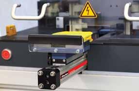
16 OSPE..BV Belt-Driven ctuators OSPE..BV Vertical Belt ctuators with Integrated Ball Bearing Guide for Z-xis pplications The OSPE..BV vertical belt actuator with integrated ball bearing guide is designed specifically for lifting movements in the Z-axis. The especially low vibration OSPE..BV vertical actuator in combination with the heavy duty series OSPE..BHD meets the highest demands in portal and handling applications. Features: High acceleration and speed Drive Shaft versions with clamp shaft or plain shaft Power transmission by belt Moving axis profile Complete motor and control packages Rated IP 20 dvantages: Fixed actuator head for low moving mass Integrated ball bearing guide for high bending moments Magnetic switch set for contactless position sensing Easy to install Low maintenance Belt tensioning end Belt Precision steel guide rail Drive head with ball bearing system Drive shaft with clamp shaft or plain shaft Magnetic switch Magnet Belt fixed end Mounting of external mass to be moved 16 Parker Hannifin Corporation Electromechanical utomation Division


17 Choose from a wide range of standard options for maximum design flexibility in a pre-assembled system. ctuator Head Orientation Drive Shaft Options Magnetic Switches Set Drive shaft with clamp shaft Magnet Magnetic Switch Magnetic Switch Magnet ll OSPE..BV actuator heads are standard with an integrated ball bearing guide and are available with either left or right side gearbox/motor mounting. Drive shaft with both clamp and plain shaft Magnetic switches with connector, mounting rail and magnets for contactless sensing of the end positions. Cable (suitable for cable chain) can be ordered separately in 5 m, 10 m or 15 m length. Drive Head Options Drive shaft with plain shaft Multi-axis Systems Standard Drive shaft with double plain shaft for parallel operation of two Z-axes with an intermediate drive shaft Simplify engineering and installation with a wide range of adapter plates and intermediate drive shafts. Mounting Rail Flexibility Tandem with additional actuator head and two additional carriers for higher bending moments. Options and ccessory Product Specifications Refer to the Options and ccessories section for complete specifications on compatible motor mounts, couplings, mounting hardware, magnetic switches, etc. The dovetailed mounting rails on the actuator housing expand its function into that of a universal system carrier. Modular system components are simply clamped on. Parker Hannifin Corporation Electromechanical utomation Division
18 OSPE..BV Belt-Driven ctuators Performance Data ctuator Size OSPE20BV OSPE25BV Lead Constant s lin mm Linear Speed (Max) v max m/s 3 5 cceleration (Max) a max m/s Repeatability µm ± 50 ± 50 Order Stroke (Max) mm 1,000 1,500 Recommended Permissible Mass (Max) kg N 650 1,430 Thrust Force (Max) F max lbs Nm Torque on Drive Shaft (Max) M max in-lb Nm Torque No Load M 0 in-lb 5 11 Load* (Max) N 1,600 2,000 F Y lbs N 1,600 3,000 F Z lbs Nm M X in-lb Bending Moment Load* (Max) Nm M Y in-lb 885 1,770 Nm M Z in-lb 885 1,770 Thrust Force (Max) F Torque (Max) M Specified Speed Specified Stroke Specified Speed Specified Stroke Zero Stroke Per Meter of Stroke Per 1 kg Moved Mass Zero Stroke Per Meter of Stroke Moved Mass of Carriage J 0 J OS J m m 0 m OS m C * Load and bending moment based on 8000 km performance <1 m/s 650 1,430 <2 m/s 605 1,288 <3 m/s 450 1,170 <4 m/s 1,052 <5 m/s 1,013 <1 m 650 1,430 <2 m 605 1,367 <1 m/s <2 m/s <3 m/s 8 31 <4 m/s 28 <5 m/s 27 <1 m <2 m kgmm 2 kgmm 2 /m kgmm 2 /kg kg kg/m kg 486 1, ,695 2, Parker Hannifin Corporation Electromechanical utomation Division
19 Base Unit Dimensions mm Drive Shaft Versions: Clamp shaft Plain Shaft Clamp Shaft with Plain Shaft Double Plain Shaft FB Mounting Holes Detail * KU x KJ (4x) CE K 10.4 V CD KD x KX (8x) ØKS Clamp Drive Shaft (shown) Plain Drive Shaft KP W X J B See Mounting Holes Detail ØKW ØKV ØKT ØKS Y x ZZ (8x) Order Stroke ctuator Size OSPE20BV OSPE25BV B C E G x H M5 x 12 M5 x 12 J K M S V W X Y x ZZ M6 x 10 M6 x10 CD CE CF EC EF FB FH KD x KX M6 x 16 KF KN KO KP KS 12 H7 16 H7 KT KU x KJ M6 x 10 M8 x 16 KV KW 36 C EC G x H (8x) E B EF CE CF M KF ØKN KO * Mounting holes for motor flange or external planetary gearbox. Drive shaft and motor mounting holes can be located on either side of carriage (see page xx for ordering information on drive shaft options). S Parker Hannifin Corporation Electromechanical utomation Division
20 OSPE..BV Belt-Driven ctuators Order Stroke Dimensions mm Standard Drive Head Tandem Drive Head Order Stroke (Required Travel + 2x Safety Distance*) KMmin Travel Order Stroke (Required Travel + KMmin + 2x Safety Distance*) ctuator Size OSPE20BV OSPE25BV KM min KM rec * Note: The mechanical end position must not be used as a mechanical end stop, thus an additional Safety Distance at both ends of travel must be incorporated into the Order Stroke. The safety distance clearance should be equivalent to the linear movement of one revolution of the drive shaft, but at least 100 mm. lso note that the use of an C motor with a VFD normally requires a larger safety clearance than that required for servo systems. For further information and design assistance, please consult the factory. 20 Parker Hannifin Corporation Electromechanical utomation Division
21 Magnetic Switch Dimensions mm The magnetic switch set provides contactless sensing of the end positions. The mounting rail and magnetic switches are mounted on the actuator drive head and the magnets are mounted in the dovetail slot on the profile. The magnetic switches are the RST-S type (connector version). Connecting cable suitable for cable chain is recommended. 35 Mounting Rail and Magnet Switch Magnet switches and magnets can be mounted on either side of drive head MC M MB Magnet Dimension (mm) OSPE20BV OSPE25BV M MB MC Parker Hannifin Corporation Electromechanical utomation Division
22 OSPE..BV Belt-Driven ctuators Ordering Information Select an order code from each of the numbered fields to create a complete OSPE..BV model order number. Include hyphens and non-selective characters as shown in example below Order Number Example: OSPE P Series OSPE Origa System Plus Electromechanical 2 Bore Size mm W x mm H mm W x mm H 3 Drive Train Vertical Belt ctuator w/integrated Ball Bearing 7 Guide 6 Order Stroke* digit input (in mm)* * Maximum standard stroke: OSPE20BV = 1000 mm; OSPE25BV = 1500 mm. For example, to OSPE..V with maximum order stroke, specify Longer strokes available upon request. Consult factory. 7 Hardware and Cover Strip Standard hardware with Parker gold (RL 1028) P cover strip 4 Carriage 0 Standard 1 Tandem (two drive heads for higher actuator stiffness) 5 Drive Shaft Configuration and Orientation (1) B Clamp Clamp Plain Plain Clamp Plain Clamp Plain Clamp shaft (left) (see Clamp Shaft with Xpress Mounted Gearbox options at right) Clamp shaft (right) (see Clamp Shaft with Xpress Mounted Gearbox options at right) Clamp shaft (left) with plain shaft for use with intermediate drive shaft for parallel actuator system** Clamp shaft (right) with plain shaft for use with intermediate drive shaft for parallel actuator system** Plain shaft idler unit*** (left) for parallel actuator system Plain shaft idler unit***(right) for parallel actuator system ** vailable with Xpress Gearbox Mounting Kit only (item 8 below) *** Only available with order code 00 No gearbox mounting kit or motor option (item 8 ) (1) Drive Shaft Orientation Drive shaft orientation is determined by viewing the actuator facing the drive head with the belt tensioning end facing up and the end cap for mounting external moved mass facing down. Belt tensioning end Clamp Shaft Left Clamp Shaft Right End cap for mounting external moved mass Note: Special drive shafts are available consult factory. 5 Clamp Shaft with Xpress Mounted Gearbox * OSPE..V Bore Size K1 PV60T-003 (gear ratio i = 3) (1) K2 PV60T-005 (gear ratio i = 5) (1) K3 PV60T-010 (gear ratio i = 10) (1) K4 PV60T-003 (gear ratio i = 3) (2) K5 PV60T-005 (gear ratio i = 5) (2) K6 PV60T-010 (gear ratio i = 10) (2) * Use appropriate order code of Clamp Shaft with Xpress Mounted Gearbox in place of order code 02 or 04. Requires Xpress Mounted Motor, Xpress Motor Mounting Kit, or Standard Motor Mounting Kit (specified in item 8) 22 Parker Hannifin Corporation Electromechanical utomation Division
23 8 Gearbox/Motor Mounting Options: Xpress Gearbox Mounting Kit* OSPE..BV Bore Size No gearbox mounting kit or motor option C1 PV40T C2 PV60T Size of Mounted Gearbox PV40 PV60 Xpress Mounted Motor with Mounted Gearbox** K0 BE233FJ-KPSN K1 BE233FJ-KPSN with brake (CM233FJ ) K2 BE344LJ-KPSN K3 BE344LJ-KPSB Xpress Motor Mounting Kit with Mounted Gearbox** C SM23xxx-N (not SM230xx-N) D BE23x, SM23xxx-L E BE34x Standard Motor Mounting Kit with Mounted Gearbox** B6 H B8 N G B9 B0 BB B4 P B3 3 J BD * See page xx for dimensions and additional information. Requires Clamp Drive Shaft (order code 02, 03, 04 or 05 from item 5) ** See page xx for dimensions and additional information. Requires Clamp Shaft with Xpress Mounted Gearbox (order code K1 thru K6 from item 5) 9 Magnetic Sensor Mounting (see page xx) 0 No sensor mounting 2 pc. N3NC-PUR-P w/mounting rail and magnet: B NPN, 3 wire, normally close, M8 plug, 0.3m PUR cable (P8S-GMSHX) 2 pc. P3NC-PUR-P w/mounting rail and magnet: E PNP, 3 wire, normally close, M8 plug, 0.3m PUR cable (P8S-GQSHX) Parker Hannifin Corporation Electromechanical utomation Division
24 OSPE..B Belt-Driven ctuators OSPE..B Belt ctuators with Internal Plain Bearing Guide for Point-to-Point pplications The OSPE..B is a completely new generation of actuators which can be integrated into any machine layout neatly and simply. Features: Integrated drive and guidance system Tandem configuration with increased carrier distance for higher moment supports Long available strokes Complete motor and control packages Diverse range of accessories and mountings Bi-parting and special options available Rated IP 54 dvantages: Precise path and position control High speed operation Easy installation Low maintenance Ideal for precise point-topoint applications Threaded mounting holes Threaded holes Corrosion resistant steel sealing band Belt tension adjustment Carriage Ball bearing Pulley Nipples for maintenance greasing Belt Slotted profile with dovetail grooves Low friction support rings Threaded holes for motor mounting (on two sides) Drive shaft Permanent magnet for contactless position sensing 24 Parker Hannifin Corporation Electromechanical utomation Division

 End cap mounting allows the actuator to be anchored at the end cap.")

25 Choose from a wide range of standard options for maximum design flexibility in a pre-assembled system. Carriage Guides Carriage Mounting Mounting Options Standard The PowerSlide linear guide roller bearings provide precision guidance for smooth travel and high dynamic or static loads. Refer to PowerSlide section, page xx for complete specifications Standard Clevis mounted carriage provides tolerance and parallelism compensation to drive external linear guides Inversion mounted carriage transfers the driving force to the opposite side (e.g. for dirty environments) End cap mounting allows the actuator to be anchored at the end cap. Profile mounting supporting long actuators or mounting the actuators on dovetail grooves. Carriage Options ProLine offers a compact aluminium roller guide for high loads and velocities. Refer to ProLine section, page xx for complete specifications Drive Shaft Options Standard The tandem carriage is recommended for added support of high moment loads. Mounting Rail Flexibility The dovetailed mounting rails on the actuator housing expand its function into that of a universal system carrier. Modular system components are simply clamped on. Plain drive shaft left Plain drive shaft left The bi-parting carriage is designed for perfectly synchronized bi-parting movements. Multi-axis Systems Simplify engineering and installation with a wide range of adapter plates and intermediate drive shafts. Double plain drive shafts for driving two actuators in parallel Options and ccessory Product Specifications Refer to the Options and ccessories section for complete specifications on compatible external linear guides, motor mounts, couplings, mounting hardware, magnetic switches. Parker Hannifin Corporation Electromechanical utomation Division
26 OSPE..B Belt-Driven ctuators Performance Data with Standard Carriage ctuator Size OSPE25B OSPE32B OSPE50B Lead Constant s lin mm Linear Speed (Max) v max m/s cceleration (Max) a max m/s Repeatability µm ± 50 ± 50 ± 50 Order Stroke (Max) mm 3,000 5,000 5,000 N Thrust Force (Max) F max lbs Nm Torque on Drive Shaft (Max) M max in-lb Nm Torque No Load M 0 in-lb Load* (Max) N F Y lbs N F Z lbs Bending Moment Load* (Max) Thrust Force (Max) F Torque (Max) M Specified Speed Specified Stroke Specified Speed Specified Stroke Zero Stroke Per Meter of Stroke Per 1 kg Moved Mass Zero Stroke Per Meter of Stroke Moved Mass of Carriage Nm M X in-lb Nm M Y in-lb Nm M Z in-lb <1 m/s <2 m/s <3 m/s <4 m/s 425 <5 m/s 425 <1 m <2 m <3 m <4 m <5 m <1 m/s <2 m/s <3 m/s <4 m/s 7.4 <5 m/s 7.4 <1 m <2 m <3 m <4 m <5 m J 0 J OS J m m 0 m OS m C kgmm 2 kgmm 2 /m kgmm 2 /kg kg kg/m kg * Load and bending moment based on 8000 km performance Parker Hannifin Corporation Electromechanical utomation Division
27 Enhanced Load and Speed Performance with ProLine and PowerSlide External Linear Guides ProLine ProLine is a precision aluminum external roller guide rail option designed for smooth, high speed operation up to 10 m/s. The ProLine option is a life time lubricated system and includes an integrated wiper to keep the guide system clean. luminium carriage Wiper cover Lateral felt wiper luminium guide rail Ground and calibrated tracks Plastic wiper Plastic cap plugs luminium roller shoe Crosswise arranged rollers on needle bearings PowerSlide luminium carriage PowerSlide is a hardened steel external guide rail option designed for harsh environments. The pre-assemble actuator option includes guide rail, vee rollers, tough protective cover, wiper systemand grease nipple for easy lubrication access. luminium clamping hub Hardened steel guide rail Roller Cover with wiper and grease nipple Performance Data with ProLine or PowerSlide Linear Guides ctuator Size OSPE25B OSPE32B OSPE50B Linear Guide Type PL25 PS25/35 PL32 PS32/44 PL50 PS50/76 Linear Guide Order Number Order Stroke (Max) mm 3,000 3,000 3,750 3,500 3,750 3,500 Load* (Max) N 1, , ,626 1,699 F Y lbs , N 1, , ,626 1,699 F Z lbs , Bending Moment Load* (Max) Zero Stroke Per Meter of Stroke Moved Mass of Carriage M X Nm in-lb , M Y Nm in-lb , ,983 1,316 M Z Nm in-lb , ,983 1,316 m 0 m OS m C kg kg/m kg * Load and bending moment based on 8000 km performance Parker Hannifin Corporation Electromechanical utomation Division
28 OSPE..B Belt-Driven ctuators Base Unit Dimensions mm Drive Shaft Versions: Plain Shaft Double Plain Shaft S KP x H (4x)* KL ØKB KG KF Order Stroke M Size 25 & 32 End Cap 10.4 CF G x H (4x) ØKO KN KC KH KE Y x ZZ ØKJ X V B FB K E C Size 50 End Cap C J CF C E * Mounting holes for motor flange or external planetary gearbox. Drive shaft and motor mounting holes can be located on either side of carriage (see page xx for ordering information on drive shaft options). G x H (4x) E ctuator Size OSPE25B OSPE32B OSPE50B B C E G x H M5 x 10 M6 x 12 M6 x 12 J K M S V X Y x ZZ M5 x 8 M6 x 10 M6 x 10 CF FB FH KB 10 j6 10 j6 16 h8 KC KE KF KG KH KJ 19 H7 26 H7 40 H7 KL KN KO KP x H M5 x 10 M6 x 12 M8 x Parker Hannifin Corporation Electromechanical utomation Division
29 Order Stroke Dimensions mm Standard Carriage Order Stroke (Required Travel + 2x Safety Distance*) Tandem Carriage Order Stroke (Required Travel + KMmin + 2x Safety Distance*) KMmin Travel Bi-Parting Carriage Order Stroke (2x Required Travel + KM min + 2x Safety Distance*) Travel KM min Travel ctuator Size OSPE25B OSPE32B OSPE50B KM min KM rec * Note: The mechanical end position must not be used as a mechanical end stop, thus an additional Safety Distance at both ends of travel must be incorporated into the Order Stroke. The safety distance clearance should be equivalent to the linear movement of one revolution of the drive shaft, but at least 100 mm. lso note that the use of an C motor with a VFD normally requires a larger safety clearance than that required for servo systems. For further information and design assistance, please consult the factory. Parker Hannifin Corporation Electromechanical utomation Division
30 OSPE..B Belt-Driven ctuators Ordering Information Select an order code from each of the numbered fields to create a complete OSPE..B model order number. Include hyphens and non-selective characters as shown in example below # $ Order Number Example: OSPE P Series OSPE Origa System Plus Electromechanical 2 ctuator Bore Size mm W x 53 mm H mm W x 67 mm H mm W x 93 mm H 3 Drive Train 0 Belt actuator with internal slider bearing 4 Carriage 0 Standard 1 Tandem (two carriages for higher load capabilities) 2 Bi-Parting (two driven carriages for opposite movements) 5 Drive Shaft Configuration and Orientation 0 Plain shaft (left) 1 Plain shaft (right) 2 Double plain shaft* (motor input left side) 6 Xpress Mounted Gearbox OSPE..B Bore Size No gearbox PV40T-003 (gear ratio i = 3)* B PV40T-005 (gear ratio i = 5)* C PV60T-003 (gear ratio i = 3)* D PV60T-005 (gear ratio i = 5)* E PV60T-010 (gear ratio i = 10)* * Requires specified Mounted Motor or Mounting Kit (select order code from 7 below) 7 Gearbox/Motor Mounting Options: Xpress Gearbox Mounting Kit* OSPE.B. Bore Size No gearbox mounting kit or motor option C0 PV40T C1 PV60T C2 PV90T Size of Mounted Gearbox PV40 PV60 Xpress Mounted Motor (with Mounted Gearbox)* L0 LV L1 HV L2 LV L3 HV K0 BE233FJ-KPSN K1 BE233FJ-KPSN with brake (CM233FJ ) K2 BE344LJ-KPSN K3 BE344LJ-KPSB M0 MPP0923D1E-KPSN M1 MPP0923D1E-KPSB M2 MPP1003D1E-KPSN M3 MPP1003D1E-KPSB M4 MPP1003R1E-KPSN M5 MPP1003R1E-KPSB Xpress Motor Mounting Kit (with Mounted Gearbox)* BE16x, SM16x B LV23x, HV23x, SM230xx-N C SM23xxx-N (not SM230xx-N) F LV34x, HV34x D BE23x, SM23xxx-L E BE34x L MPP092, MPJ092 4 MPP100, MPJ100 Standard Motor Mounting Kit (with Mounted Gearbox)* PV40 PV PV40 PV60 B5 B0 M B1 B6 B2 H BB 2 B4 BJ P B7 B3 B8 1 N 3 G J B9 BD B BF * See page xx for dimensions and additional information. 30 Parker Hannifin Corporation Electromechanical utomation Division
31 8 Stroke* digit input (in mm) * Maximum standard stroke: OSPE25B = mm; OSPE32B and OSPE50B = mm Longer strokes available upon request. Consult factory. 9 Hardware and Cover Strip Standard hardware with Parker gold (RL 1028) P cover strip 0 External Guide Rail OSPE..B Bore Size No external guide rail 6 ProLine PL25, PL32, PL50* F PowerSlide PS25/35* G PowerSlide PS32/44* I PowerSlide PS50/76* * Requires standard carriage (select order code 0 from 4 above) See page xx for dimensions and additional information.! External Guide Rail Orientation Guide Rail (right) with order code 0 from item 5 (plain shaft left) Guide Rail (left) with order code 0 from item 5 (plain shaft left) Guide Rail (left) with order code 1 from item 5 (plain shaft right) Guide Rail (right) with order code 1 from item 5 (plain shaft right) Guide Rail (right) with order code 2 from item 5 (double shaft motor input left End Cap Mounting (see page xx) 0 No end cap mounting 1 1 pair 1 (size 25, 32) or C1 (size 50) 5 1 pair B4 (size 25, 32) 4 1 pair C4 (size 50) # Profile Mounting (see page xx) 0 No profile mounting 1 1 pair E1 4 2 pair E1 7 3 pair E1 3 1 pair ME 6 2 pair ME 9 3 pair ME M 1 pair E4 Q 2 pair E4 T 3 pair E4 $ Magnetic Sensor Mounting (see page xx) 0 No sensor mounting 1 pc. N3NO-PUR-P: NPN, 3 wire, normally open, M8 plug, 0.3m PUR cable (P8S-GNSHX) 2 pc. N3NC-PUR-P: NPN, 3 wire, normally close, B M8 plug, 0.3m PUR cable (P8S-GMSHX) 1 pc. N3NO-PUR-P (P8S-GNSHX) and C 2 pc. N3NC-PUR-P (P8S-GMSHX) 1 pc. P3NO-PUR-P: PNP, 3 wire, normally open, D M8 plug, 0.3m PUR cable (P8S-GPSHX) 2 pc. P3NC-PUR-P: PNP, 3 wire, normally close, E M8 plug, 0.3m PUR cable (P8S-GQSHX) 1 pc. P3NO-PUR-P (P8S-GPSHX) and F 2 pc. P3NC-PUR-P (P8S-GQSHX) 1 Guide Rail (left) with order code 2 from item 5 (double shaft motor input left side) Parker Hannifin Corporation Electromechanical utomation Division
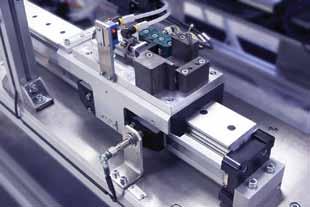
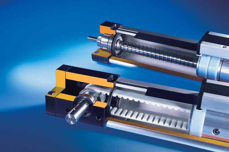
32 OSPE..SB/ST Screw-Driven ctuators OSPE..SB Ball Screw ctuators for High ccuracy OSPE..ST Trapezoidal Screw ctuators for Intermittent Duty The OSPE..SB/ST is a completely new generation of screw-driven actuators which can be integrated into any machine layout neatly and simply. The SB design features a ball screw drive available with a choice of optimal screw pitches for high accuracy and optimum speed, load performance. The ST design utilizes a trapezoidal screw which is ideal for lower speed, intermittent duty applications. ST models are inherently a self-locking device for power off load holding capability. Features: ll models feature internal plain bearing Integrated drive and guidance system Complete motor and control packages Specialized optional configurations available Diverse range of accessories and mountings Rated IP 54 dvantages: ccurate path and position control High force output Easy installation Excellent slow speed characteristics Ideal for precise traverse operations such as machine feeds, and lifting applications Drive shaft Corrosion resistant steel sealing band Threaded holes Low friction support rings Carriage Double row angular contact ball bearing Nipples for maintenance greasing End cap screws with threaded mounting holes Ball screw or trapezoidal screw spindles. Ball screws are available in a choice of screw pitches: OSPE.25SB: 5 mm OSPE.32SB: 5, 10 mm OSPE.50SB: 5, 10, 25 mm Slotted profile with dovetail grooves SB models feature an internally protected ball-screw nut ST models have a plastic nut Permanent magnet for contactless position sensing 32 Parker Hannifin Corporation Electromechanical utomation Division


33 Choose from a wide range of standard options for maximum design flexibility in a pre-assembled system. Carriage Guides Carriage Mounting Mounting Options Standard Standard End cap mounting The PowerSlide linear guide roller bearings provide precision guidance for smooth travel and high dynamic or static loads. Refer to PowerSlide section, page xx for complete specifications ProLine offers a compact aluminium roller guide for high loads and velocities. Refer to ProLine section, page xx for complete specifications Carriage Options Standard Clevis mounted carriage provides tolerance and parallelism compensation to drive external linear guides Inversion mounted carriage transfers the driving force to the opposite side (e.g. for dirty environments) Options and ccessory Product Specifications Refer to the Options and ccessories section for complete specifications on compatible external linear guides, motor mounts, couplings, mounting hardware, magnetic switches. Profile mounting on the dovetail groves recommended to support long actuators Mounting Rail Flexibility The dovetailed mounting rails on the SB actuator housing expand its function into that of a universal system carrier. Modular system components are simply clamped on. Magnetic Switches Magnetic switches provide contactless position sensing of end stop and intermediate carrier positions The tandem carriage (SB models only) is recommended for added support of high moment loads. Parker Hannifin Corporation Electromechanical utomation Division
34 OSPE..SB/ST Screw-Driven ctuators Performance Data with Standard Carriage ctuator Size OSPE25 OSPE32 OSPE50 Screw Type (SB-Ball; ST-Trapezoidal) SB ST SB SB ST SB SB SB ST Lead Constant s lin mm Linear Speed (Max) v max m/s ,250 5 Radial Speed (Max) rpm 3,000 1,500 3,000 3,000 1,500 3,000 3,000 3,000 1,500 cceleration (Max) a max m/s Repeatability µm ± 50 ± 500 ± 50 ± 50 ± 500 ± 50 ± 50 ± 50 ± 500 Order Stroke (Max) mm 1,100 1,100 2,000 2,000 2,000 3,200 3,200 3,200 2,400 N , ,300 1,300 1,450 1,350 2,500 Thrust Force (Max) F max lbs Torque on Drive Shaft (Max) M max Nm in-lb Nm Torque No Load M 0 in-lb N ,200 1,200 1,000 3,000 3,000 3,000 1,500 F Y lbs Load* (Max) N ,200 1,200 1,000 3,000 3,000 3,000 1,500 F Z lbs Bending Moment Load* (Max) Speed (Max) VMX Specified Stroke Zero Stroke Per Meter of Stroke Per 1 kg Moved Mass Zero Stroke Per Meter of Stroke Moved Mass of Carriage Nm M X in-lb Nm M Y in-lb ,372 Nm M Z in-lb mm , mm , mm , mm , mm mm mm mm mm mm mm mm mm mm mm mm J 0 J OS J m m 0 m OS m C kgmm 2 kgmm 2 /m kgmm 2 /kg kg kg/m kg * Load and bending moment based on 8000 km performance Parker Hannifin Corporation Electromechanical utomation Division
35 Enhanced Load and Speed Performance with ProLine and PowerSlide External Linear Guides ProLine Wiper cover Lateral felt wiper luminium carriage ProLine is a precision aluminum external roller guide rail option designed for smooth, high speed operation up to 10 m/s. The ProLine option is a life time lubricated system and includes an integrated wiper to keep the guide system clean. luminium guide rail Plastic wiper Plastic cap plugs Ground and calibrated tracks luminium roller shoe Crosswise arranged rollers on needle bearings PowerSlide luminium carriage PowerSlide is a hardened steel external guide rail option designed for harsh environments. The pre-assemble actuator option includes guide rail, vee rollers, tough protective cover, wiper systemand grease nipple for easy lubrication access. luminium clamping hub Hardened steel guide rail Roller Cover with wiper and grease nipple Performance Data with ProLine or PowerSlide Linear Guides ctuator Size OSPE25SB/ST OSPE32SB/ST OSPE50SB/ST Linear Guide Type PL25 PS25/35 PL32 PS32/44 PL50 PS50/76 Linear Guide Order Number Order Stroke (Max) mm 1,000 1,000 2,000 2, * 3200* Load** (Max) N 1, , ,626 1,699 F Y lbs , N 1, , ,626 1,699 F Z lbs , Bending Moment Load* (Max) Zero Stroke Per Meter of Stroke Moved Mass of Carriage M X Nm in-lb , M Y Nm in-lb , ,983 1,316 M Z Nm in-lb , ,983 1,316 m 0 m OS m C kg kg/m kg * Max order stroke for ST models is 2400mm ** Load and bending moment based on 8000 km performance Parker Hannifin Corporation Electromechanical utomation Division
36 OSPE..SB/ST Screw-Driven ctuators Base Unit Dimensions mm Drive Shaft Versions: Plain Shaft ØKN ØKB Order Stroke M CF Size 25 & 32 End Cap 10.4 G x H (4x) Optional Plain Shaft with Keyway KR KP KO KL KD Y x ZZ X J V B FB K CF C E E C Size 50 End Cap C KS - ØKB KL G x H (4x) E ctuator Size OSPE25SB/ST OSPE32SB/ST OSPE50SB/ST B C E G x H M5 x 10 M6 x 12 M6 x 12 J K M S V X Y x ZZ M5 x 8 M6 x 10 M6 x 10 CF FB FH KB 6 h7 10 h7 15 h7 KD KL* KN KO KP 2 P9 3 P9 5 P9 KR KS ,0 * KL dimensions with option 4 keyway: OSPE25SB/ST: 24 mm OSPE32SB/ST: 41 mm OSPE50SB/ST: 58 mm 36 Parker Hannifin Corporation Electromechanical utomation Division
37 Order Stroke Dimensions mm Standard Carriage Order Stroke (Required Travel + 2x Safety Distance*) Tandem Carriage (SB models only) KMmin Order Stroke (Required Travel + KMmin + 2x Safety Distance*) Travel ctuator Size OSPE25SB/ST OSPE32SB/ST OSPE50SB/ST KM min KM rec * Note: The mechanical end position must not be used as a mechanical end stop, thus an additional Safety Distance at both ends of travel must be incorporated into the Order Stroke. The safety distance clearance should be equivalent to the linear movement of one revolution of the drive shaft, but at least 100 mm. lso note that the use of an C motor with a VFD normally requires a larger safety clearance than that required for servo systems. For further information and design assistance, please consult the factory. Parker Hannifin Corporation Electromechanical utomation Division
38 OSPE..SB/ST Screw-Driven ctuators Ordering Information Select an order code from each of the numbered fields to create a complete OSPE..SB or ST model order number. Include hyphens and non-selective characters as shown in example below # $ Order Number Example: OSPE P Series OSPE Origa System Plus Electromechanical 2 ctuator Bore Size mm W x 53 mm H mm W x 67 mm H mm W x 93 mm H 3 Drive Train SB Ball screw actuator with internal slider 1 bearing ST Trapezoidal screw actuator with internal 2 slider bearing 4 Carriage 0 Standard Tandem (two carriages for higher load 1 capabilities (available with SB Drive train only) 5 Screw Lead OSPE..SB Bore Size Lead 5 mm 4 Lead 10 mm 5 Lead 25 mm OSPE..ST Bore Size Lead 4 mm 6 Lead 6 mm 6 Xpress Mounted Gearbox OSPE..SB/ST Bore Size No gearbox PV40T-003 (gear ratio i = 3)* B PV40T-005 (gear ratio i = 5)* C PV60T-003 (gear ratio i = 3)* D PV60T-005 (gear ratio i = 5)* E PV60T-010 (gear ratio i = 10)* * Requires specified Mounted Motor or Mounting Kit (select order code from 7 below) 7 Gearbox/Motor Mounting Options: Xpress Gearbox Mounting Kit* OSPE..SB/ST Bore Size No gearbox mounting kit or motor option C0 PV40T C1 PV60T C2 PV90T Size of Mounted Gearbox PV40 PV60 Xpress Mounted Motor (with Mounted Gearbox)* L0 LV L1 HV L2 LV L3 HV K0 BE233FJ-KPSN K1 BE233FJ-KPSN with brake (CM233FJ ) K2 BE344LJ-KPSN K3 BE344LJ-KPSB M0 MPP0923D1E-KPSN M1 MPP0923D1E-KPSB M2 MPP1003D1E-KPSN M3 MPP1003D1E-KPSB M4 MPP1003R1E-KPSN M5 MPP1003R1E-KPSB Xpress Motor Mounting Kit (with Mounted Gearbox)* BE16x, SM16x B LV23x, HV23x, SM230xx-N C SM23xxx-N (not SM230xx-N) F LV34x, HV34x D BE23x, SM23xxx-L E BE34x L MPP092, MPJ092 4 MPP100, MPJ100 Standard Motor Mounting Kit (with Mounted Gearbox)* PV40 PV PV40 PV60 B5 B0 M B1 B6 B2 H BB 2 B4 BJ P B7 B3 B8 1 N 3 G J B9 BD B BF * See page xx for dimensions and additional information. 38 Parker Hannifin Corporation Electromechanical utomation Division
39 8 Stroke* digit input (in mm) * Maximum standard stroke: OSPE25SB/ST = mm; OSPE32SB/ST = mm; OSPE50ST = mm; OSPE50SB = mm Longer strokes available upon request consult factory 9 Hardware and Cover Strip Standard hardware with Parker gold (RL 1028) P cover strip 0 External Guide Rail OSPE..SB/ST Bore Size No external guide rail 6 ProLine PL25, PL32, PL50* F PowerSlide PS25/35* G PowerSlide PS32/44* I PowerSlide PS50/76* * Requires standard carriage (select order code 0 from 4 above) See page xx for dimensions and additional information.! External Guide Rail Orientation 0 1 Guide Rail (right) with order code 0 from item 5 Guide Rail (left) with order code 0 from item End Cap Mounting (see page xx) 0 No end cap mounting 1 1 pair 1 (size 25, 32) or C1 (size 50) 5 1 pair B4 (size 25, 32) 4 1 pair C4 (size 50) # Profile Mounting (see page xx) 0 No profile mounting 1 1 pair E1 4 2 pair E1 7 3 pair E1 3 1 pair ME 6 2 pair ME 9 3 pair ME M 1 pair E4 Q 2 pair E4 T 3 pair E4 $ Magnetic Sensor Mounting (see page xx) 0 No sensor mounting 1 pc. N3NO-PUR-P: NPN, 3 wire, normally open, M8 plug, 0.3m PUR cable (P8S-GNSHX) 2 pc. N3NC-PUR-P: NPN, 3 wire, normally close, B M8 plug, 0.3m PUR cable (P8S-GMSHX) 1 pc. N3NO-PUR-P (P8S-GNSHX) and C 2 pc. N3NC-PUR-P (P8S-GMSHX) 1 pc. P3NO-PUR-P: PNP, 3 wire, normally open, D M8 plug, 0.3m PUR cable (P8S-GPSHX) 2 pc. P3NC-PUR-P: PNP, 3 wire, normally close, E M8 plug, 0.3m PUR cable (P8S-GQSHX) 1 pc. P3NO-PUR-P (P8S-GPSHX) and F 2 pc. P3NC-PUR-P (P8S-GQSHX) Parker Hannifin Corporation Electromechanical utomation Division
40 Linear Guide Options PowerSlide Hardened Steel Roller External Guide System Designed for Harsh Environments PowerSlide is a hardened steel external guide rail option designed for harsh environments. The pre-assemble actuator option includes guide rail, vee rollers, tough protective cover, wiper systemand grease nipple for easy lubrication access. PowerSlide guides are offered in several sizes and are available on all sizes of OSPE..B and OSPE..SB/ ST Series ctuators. Features: nodized aluminium guide carriage with double row ball bearing vee rollers Hardened steel guide rail Choice of guide sizes Maximum speed of 3 m/s Tough roller cover with wiper and grease nipple vailable on any actuator length luminium carriage luminium clamping hub dvantages: Recommended for high loads and moments High precision, smooth operation Can be installed in any position Retrofits existing actuators Hardened steel guide rail Roller Cover with wiper and grease nipple 40 Parker Hannifin Corporation Electromechanical utomation Division
41 PowerSlide Performance Data with OSPE..B ctuator Model OSPE25B OSPE32B OSPE50B PowerSlide Model Number PS 25/35 PS 32/44 PS 50/76 PowerSlide Order Number Order Stroke (Max) mm 3,000 3,500 3,500 Load* (Max) N ,699 F Y lbs N ,699 F Z lbs Bending Moment Load* (Max) M X Nm in-lb M Y Nm in-lb ,316 M Z Nm in-lb ,316 Weight 0 Stroke m O Weight (kg) per Meter of Stroke m OS Moved Mass of Carriage (kg) m C * Load and bending moment based on 8000 km performance PowerSlide Performance Data with OSPE..SB/ST ctuator Model OSPE25SB/ST OSPE32SB/ST OSPE50SB/ST PowerSlide Model Number PS 25/35 PS 32/44 PS 50/76 PowerSlide Order Number Order Stroke (Max) mm 1,000 2, ** Load* (Max) N ,699 F Y lbs N ,699 F Z lbs Nm M X in-lb Bending Moment Nm M Load* (Max) Y in-lb ,316 Nm M Z in-lb ,316 Weight 0 Stroke m O Weight (kg) per Meter of Stroke m OS Moved Mass of Carriage (kg) m C * Load and bending moment based on 8000 km performance ** Max order stroke for ST models is 2400mm Parker Hannifin Corporation Electromechanical utomation Division
42 Linear Guide Options PowerSlide Dimensions with OSPE..B (mm) Order Stoke + 2 x + Z* KG + Z* Order Stoke B EF FF CC FS EE FT EG JJ BB Z x EF (6x) *Note: The dimension Z must be added CF to. Please also note the effect of dimension Z when retrofitting a PowerSlide Guide, please consult factory for assistance. GG Model # B Z Z BB CC CF EE EF EG FF FS FT GG JJ KG PS 25/ M PS 32/ M PS 50/ M Parker Hannifin Corporation Electromechanical utomation Division
43 PowerSlide Dimensions with OSPE..SB/ST (mm) Order Stroke + 2 x Order Stroke EF FF CC FS EE FT B JJ BB Z x EF (6x) B EG CF GG Model # B Z BB CC CF EE EF EG FF FS FT GG JJ PS 25/ M PS 32/ M PS 50/ M Parker Hannifin Corporation Electromechanical utomation Division

44 Linear Guide Options ProLine External Roller Guide System for Smooth, High-Speed Operation ProLine is a precision aluminum external roller guide rail option designed for smooth, high speed operation up to 10 m/s. The ProLine ball bushing guide for heavy loads and speed. The ProLine option is a life time lubricated system and includes an integrated wiper to keep the guide system clean. PowerSlide guides are offered in several sizes and are available on all sizes of OSPE..B and OSPE..SB/ ST Series ctuators. Features: nodized aluminium guide carriage with double row ball bearing vee rollers Hardened steel guide rail Choice of guide sizes Maximum speed of 10 m/s Tough roller cover with integrated wiper system Lifetime lubrication vailable on any actuator length Lateral felt wiper luminium guide rail luminium carriage Plastic wiper Plastic cap plugs Ground and calibrated tracks dvantages: High precision High velocities (10 m/s) Smooth operation low noise Can be installed in any position Retrofits existing actuators luminium roller shoe Crosswise arranged rollers on needle bearings 44 Parker Hannifin Corporation Electromechanical utomation Division
45 ProLine Performance Data with OSPE..B ctuator Series/Size OSPE25B OSPE32B OSPE50B ProLine Model Size PL 25 PL 32 PL 50 ProLine Order Number Order Stroke (Max) mm 3,000 3,750 3,750 Load* (Max) N 1,548 2,117 5,626 F Y lbs ,265 N 1,548 2,117 5,626 F Z lbs ,265 Bending Moment Load* (Max) M X Nm in-lb ,770 M Y Nm in-lb 611 1,168 3,983 M Z Nm in-lb 611 1,168 3,983 Weight 0 Stroke Weight (kg) per Meter of Stroke Weight Carriage (kg) * Max order stroke for ST models is 2400mm ** Load and bending moment based on 8000 km performance ProLine Performance Data with OSPE..SB/ST ctuator Series/Size OSPE25SB/ST OSPE32SB/ST OSPE50SB/ST ProLine Model Size PL 25 PL 32 PL 50 ProLine Order Number Order Stroke (Max) mm 1,000 2, * Load* (Max) N 1,548 2,117 5,626 F Y lbs ,265 N 1,548 2,117 5,626 F Z lbs ,265 Nm M X in-lb ,770 Bending Nm Moment M Y in-lb 611 1,168 3,983 Load* (Max) Nm M Z in-lb 611 1,168 3,983 Weight 0 Stroke Weight (kg) per Meter of Stroke Weight Carriage (kg) * Max order stroke for ST models is 2400mm ** Load and bending moment based on 8000 km performance Parker Hannifin Corporation Electromechanical utomation Division
46 Linear Guide Options ProLine Dimensions with OSPE..B (mm) KG + Z* ZZ Order Stoke + 2 x + Z* Z Order Stoke FF EC FS EG EE FT JJ DD B M CF GG *Note: The dimension Z must be added to. Please also note the effect of dimension Z when retrofitting a ProLine Guide, please consult factory for assistance. BB Model # B J M Z Z BB DD CF EC EE EG FF FS FT GG JJ KG ZZ PL M PL M PL M Parker Hannifin Corporation Electromechanical utomation Division
47 ProLine Dimensions with OSPE..SB/ST (mm) Order Stoke + 2 x + Z* ZZ Z Order Stoke FF EC FS EG EE FT B J JJ DD B M CF GG BB Model # B J M Z BB DD CF EC EE EG FF FS FT GG JJ ZZ PL M PL M PL M Parker Hannifin Corporation Electromechanical utomation Division


48 Linear Guide Options PowerSlide and ProLine End Cap and Profile Mountings ProLine PowerSlide /25 25/35 25/44 32/35 32/44 50/60 50/76 Standard Type 1 End Cap Mounting Reinforced Type B4 Block Type C4 Narrow Type D1 Profile Mounting Wide Type E1 Type E4 Mounting position any side Mounting position carriage side only (3 or 9 o clock position) Mounting position carriage top only (12 o clock position) Ordering Information OSPE End Cap Mount* Order Number Profile Mount* Order Number Bore Size Type 1 Type B4 Type C4 Type D1 Type E1 Type E FIL 18160FIL 20008FIL 20009FIL 20354FIL FIL 18165FIL 20157FIL 20158FIL 20357FIL FIL 20162FIL 20163FIL 20363FIL * End Cap Mounts and Profile Mounts are supplied individually 48 Parker Hannifin Corporation Electromechanical utomation Division
49 Dimensions Linear Guide End Cap Mountings (mm) E Standard End Cap Type 1 E Reinforced End Cap Type B4 E Block End Cap Type C4 ØU F E ØU F CL E ØU F E B DG CL C D B DG C D E DG B C D OSPE E (by End Cap type) F (by End Cap type) Bore Size B C D 1 B4 C4 1 B4 C4 CL DG E ØU Dimensions Linear Guide End Profile Mountings (mm) DQ Narrow Profile Mount Type D1 DQ Wide Profile Mount Type E1 & E4 DE EM EQ F DF DT R DH F DO DP EF EQ EN DK DM DN ØUU ØU F (Type E4) DS F (Type E1) DH DO DP DR DR (Type E4) (Type E1) OSPE F (by Profile type) DR (by Profile type) Bore Size D1 E1 E4 D1 E1 E4 DE DF DH DK DM DN OSPE Bore Size DO DP DQ DS DT EF EM EN EQ R ØU ØUU M M M6 7.0 Parker Hannifin Corporation Electromechanical utomation Division
 OSPE20BHD 16213FIL OSPE25BHD 12266FIL OSPE32BHD 12267FIL OSPE50BHD 12268FIL E ØU E F Type CN Dimensions mm B DG C D Model-Size B C D E F G DG E U OSPE20BHD 40 10.0 20 20 22 74 27 6.")
 Type CO Order Instructions OSPE Compatible Type CO Order No.")
50 ctuator Mounting Options Type CN End Cap Mounts (Bottom Mounted Block) Type CN Order Instructions OSPE Compatible Type CN Order No.* Weight* (kg) OSPE20BHD 16213FIL OSPE25BHD 12266FIL OSPE32BHD 12267FIL OSPE50BHD 12268FIL E ØU E F Type CN Dimensions mm B DG C D Model-Size B C D E F G DG E U OSPE20BHD OSPE25BHD OSPE32BHD OSPE50BHD Type CO End Cap Mounts (Side Mounted Block) Type CO Order Instructions OSPE Compatible Type CO Order No.* Weight* (kg) OSPE20BHD OSPE25BHD OSPE32BHD OSPE50BHD 16241FIL 16245FIL 16246FIL 16247FIL D C G B Type CO Dimensions mm G E F ØU ØUH Model-Size B C D E F G DG U UH OSPE20BHD OSPE25BHD OSPE32BHD OSPE50BHD Parker Hannifin Corporation Electromechanical utomation Division
 OSPE25B/SB/ST 18156FIL OSPE32B/SB/ST 18161FIL OSPE50B/SB/ST Type C1 End Cap Mounts (Block) Type CO Order Instructions OSPE Compatible Type C1 Order No.")

51 Type 1 End Cap Mounts (Standard) Type CO Order Instructions OSPE Compatible Type 1 Order No.* Weight* (kg) OSPE25B/SB/ST 18156FIL OSPE32B/SB/ST 18161FIL OSPE50B/SB/ST Type C1 End Cap Mounts (Block) Type CO Order Instructions OSPE Compatible Type C1 Order No.* Weight* (kg) OSPE25B/SB/ST OSPE32B/SB/ST OSPE50B/SB/ST 18166FIL Type 1 Type C1 E F E ØU F E E ØU B DG CL C D B E DG C D Type 1 and C1 Dimensions mm Model-Size B C D E F CL DG E U OSPE25B/SB/ST OSPE32B/SB/ST OSPE50B/SB/ST Parker Hannifin Corporation Electromechanical utomation Division
 20 12278FIL 0.3 25 12278FIL 12278FIL 12278FIL 0.3 32 12279FIL 12279FIL 12279FIL 0.4 50 12280FIL 12280FIL 12280FIL 0.")
 20 20008FIL 25 20008FIL 20008FIL 20008FIL 32 20157FIL 20157FIL 20157FIL 50 15534FIL 20162FIL 20162FIL Type E1 Profile Mounts (with 2 through holes) Type D1")
 20 20009FIL 25 20009FIL 20009FIL 20009FIL 32 20158FIL 20158FIL 20158FIL 50 15536FIL 20163FIL 20163FIL * ME mountings are supplied as a pair, Order No.")
52 ctuator Mounting Options Type ME Profile Mounts (with 3 through holes) Type ME Order Instructions OSPE Type ME Order No.* Bore SIze OSPE..BHD OSPE..B OSPE..SB/ST Weight* (kg) FIL FIL 12278FIL 12278FIL FIL 12279FIL 12279FIL FIL 12280FIL 12280FIL 0.8 Type D1 Profile Mounts (with internal threads) Type D1 Order Instructions OSPE Type D1 Order No.* Bore SIze OSPE..BHD OSPE..B OSPE..SB/ST Weight* (kg) FIL FIL 20008FIL 20008FIL FIL 20157FIL 20157FIL FIL 20162FIL 20162FIL Type E1 Profile Mounts (with 2 through holes) Type D1 Order Instructions OSPE Type E1 Order No.* Bore SIze OSPE..BHD OSPE..B OSPE..SB/ST Weight* (kg) FIL FIL 20009FIL 20009FIL FIL 20158FIL 20158FIL FIL 20163FIL 20163FIL * ME mountings are supplied as a pair, Order No. and Weight are for two ME mountings; D1 and E1 mountings are supplied individually, Order No. and Weight are for one D1 or E1 mounting. 52 Parker Hannifin Corporation Electromechanical utomation Division
OSPE Origa System Plus. Belt-Driven and Screw-Driven Modular Electric Actuators
 aerospace climate control electromechanical filtration fluid & gas handling hydraulics pneumatics process control sealing & shielding OSPE Origa System Plus Belt-Driven and Screw-Driven Modular Electric
Linear Drive with Toothed Belt Series OSP-E..B. Contents Description Overview Technical Data Dimensions Order Instructions 46
 Linear Drive with Toothed Belt Contents Description Page Overview 35-38 Technical Data 39-43 Dimensions 44-45 Order Instructions 46 35 The System Concept ELECTRIC LINEAR DRIVE FOR POINT-TO-POINT APPLICATIONS
Linear Drive with Toothed Belt and Integrated Guide with Recirculating Ball Bearing Guide with Roller Guide Series OSP-E..BHD
 Linear Drive with and Integrated Guide with Recirculating Ball Bearing Guide with Roller Guide Contents Description Page Overview 11-14 Version with Recirculating Ball Bearing Guide Technical Data 15-17
OSPE..BHD Belt-Driven Actuators
 OSPE..BHD Belt-Driven Actuators Actuators for High-Speed, Long Travel, Heavy Duty Applications The OSPE..BHD is the highest capacity belt-driven actuator in the OSPE family. The integrated ball bearing
Linear Actuator with Toothed Belt Series OSP-E..B
 Linear Actuator with Toothed Belt Series OSP-E..B Contents Description Data Sheet No. Page Overview 1.20.001E 21-24 Technical Data 1.20.002E-1 to 5 25-29 Dimensions 1.20.002E-6 30 Order Instructions 1.20.002E-7
Linear Drive with Ball Screw Drive Series OSP-E..SB
 Linear Drive with Ball Screw Drive Series OSP-E..SB Contents Description Data Sheet No. Page Overview 1.30.001E 47-50 Technical Data 1.30.002E-1 to 5 51-55 Dimensions 1.30.002E-6, -7 56-57 Order instructions
Linear Actuator with Ball Screw Series OSP-E..S. Contents Description Overview Technical Data Dimensions 79
 Linear Actuator with Ball Screw Series OSP-E..S Contents Description Page Overview 71-74 Technical Data 75-78 Dimensions 79 71 The System Concept ELECTRIC LINEAR ACTUATOR FOR HIGH ACCURACY APPLICATIONS
Vertical Linear Drive with Toothed Belt and Integrated Recirculating Ball Bearing Guide Series OSP-E..BV
 Vertical Linear Drive with Toothed Belt and Integrated Recirculating Ball Bearing Guide Series OSP-E..BV Contents Description Page Overview 25-28 Technical Data 29-33 Dimensions 34 Order Instructions 35
Vertical Linear Drive with Toothed Belt and Integrated Recirculating Ball Bearing Guide Series OSP-E..BV
 Vertical Linear Drive with and Integrated Recirculating Ball Bearing Guide Series OSP-E..BV Contents Description Page Overview 25-28 Technical Data 29-31 Dimensions 32-33 25 Parker Hannifin Corporation
Linear Actuator with Ball Screw Series OSP-E..S. Contents Description Overview Technical Data Dimensions 89
 Linear Actuator with Ball Screw Series OSP-E..S Contents Description Page Overview 79-82 Technical Data 83-88 Dimensions 89 79 The System Concept ELECTRIC LINEAR ACTUATOR FOR HIGH ACCURACY APPLICATIONS
Vertical Linear Drive with Toothed Belt and Integrated Recirculating Ball Bearing Guide Series OSP-E..BV
 Vertical Linear Drive with and Integrated Recirculating Ball Bearing Guide Series OSP-E..BV Overview...25-28 Technical Data...29-31 Dimensions...32-33 25 Features TOOTHED BELT DRIVE FOR VERTICAL MOVEMENTS
OSPE..B Belt-Driven Actuators
 OSPE..B Belt-Driven s s for Point-to-Point Applications The field-proven OSPE..B design is the industry standard for the widest array of point-to-point linear traverse applications. ompact size and maximum
Linear Actuator with Toothed Belt and Integrated Roller Guide Series OSP-E..BHD
 inear Actuator with Toothed Belt and Integrated Roller Guide Series OSP-E..BHD Contents Description Data Sheet No. Page Overview 1.15.001E 11-14 Technical Data 1.15.002E-1 to 3 15-17 Dimensions 1.15.002E-4
Modular Electric Actuators OSP-E ORIGA SYSTEM PLUS
 Modular Electric Actuators OSP-E ORIGA SYSTEM PLUS Sizing Performance Overview Maximum Loadings Sizing of Actuator The following steps are recommended for selection : 1. Check that maximum values in the
Modular Electric Actuators OSP-E ORIGA SYSTEM PLUS
 Modular Electric Actuators OSP-E ORIGA SYSTEM PLUS Contents Modular Electric Actuators OSP Concept Origa System Plus Electric Actuator OSP-E, Modular Components - Overview Page 4 Applications for OSP-E
Modular Electric Actuators OSP-E ORIGA SYSTEM PLUS
 Modular Electric Actuators OSP-E ORIGA SYSTEM PLUS Mounting Dimensions for Motor and Gears Code Description A B* D E F G for motor and gears with clearance mounting holes A0 SY563T 66,50 M4 38,10 2,50
Linear Actuator with Toothed Belt and Integrated Guide with Roller Guide with Recirculating Ball Bearing Guide. Series OSP-E..BHD
 inear ctuator with Toothed elt and Integrated Guide with Roller Guide with Recirculating all earing Guide Series OSP-E..HD Contents Description Page Overview 11-14 Version with Roller Guide Technical Data
OSP-E Series Electric Linear Drives and Guides ENGINEERING YOUR SUCCESS. Catalog aerospace. electromechanical
 aerospace climate control electromechanical filtration fluid & gas handling hydraulics pneumatics process control sealing & shielding OSP-E Series Electric Linear Drives and Guides Catalog 0950-2 ENGINEERING
Modular Electric Actuators OSP-E ORIGA SYSTEM PLUS
 Modular Electric Actuators ORIGA SYSTEM PLUS Contents Modular Electric Actuators OSP Concept Origa System Plus Electric Actuator, Modular Components - Overview 4 Applications for Actuators 8 Belt Actuator..BHD,
Rodless Pneumatic Cylinders Series OSP-P
 Rodless Pneumatic Cylinders Series OSP-P System Concepts & Components... 2-5 Technical Data... 7-9 Dimensions... 10-15 Active rakes... 16-19 Accessories (Mounts & Supports)... 20-29 Ordering Information...30
Linear Guides Series OSP-E
 Linear Guides Series OSP-E NEW Contents Description Page Overview 101-102 Plain Bearing SLIDELINE 103-104 Roller Guide POWERSLIDE 105-108 Aluminium Roller Guide PROLINE 109-111 Heavy-duty guide HD 113-115
Modular Electrical Linear Drives Catalog 0950
 aerospace climate control electromechanical filtration fluid & gas handling hydraulics pneumatics process control sealing & shielding Modular Electrical Linear Drives Catalog 0950 OSP-E Series Electric
Linear Guides Series OSP-E
 Linear Guides Series OSP-E NEW Contents Description Data Sheet No. Page Overview 1.40.020E 101-102 Plain Bearing SLIDELINE 1.40.021E 103-104 Roller Guide POWERSLIDE 1.40.022E 105-108 Aluminium Roller Guide
Linear Guides Series OSP-P
 Linear Guides Series OSP-P NEW Contents Description Page Overview 31-32 Plain bearing guide SLIDELINE 33-34 Roller guide POWERSLIDE 35-38 Aluminium roller guide PROLINE 39-40 Recirculating ball bearing
Linear Guides Pneumatic linear drive Series OSP - P Adaptive modular system The Ortman System Plus OSP provides a comprehensive range of linear guides
 PNEUMATIC GROUP Guides ORTMAN SYSTEM PLUS LINEAR GUIDES FOR OSP-P 19 Linear Guides Pneumatic linear drive Series OSP - P Adaptive modular system The Ortman System Plus OSP provides a comprehensive range
ORIGA SYSTEM PLUS. Modular Electric Linear Drive Systems
 ORIGA SYSTEM PLUS Modular Electric Linear Drive Systems OSP ORIGA SYSTEM PLUS ELECTRIC ACTUATOR Attention! Contact Hoerbiger-Origa for sizing software and/or technical assistance 630-871-8300 Application
ORIGA Pneumatic Linear Drives OSP-L
 ORIGA Pneumatic Linear Drives OSP-L Very long lifetime and lowest leakage A NEW Modular Linear Drive System With this second generation linear drive Parker Origa offers design engineers complete flexibility.
Linear Actuator with Ball Screw and Extending Rod Series OSP-E..SBR. Contents Description Overview Technical Data Dimensions 110
 Linear Actuator with Ball Screw and xtending Rod Series OSP-..SBR Contents Description Page Overview 103-106 Technical Data 107-109 Dimensions 110 103 The System Concept LCTRIC LINAR ACTUATOR FOR PRCIS
ORIGA SYSTEM PLUS. Modular Electric Linear Drive Systems
 ORIGA SYSTEM PLUS Modular Electric Linear Drive Systems 1 2 3 4 5 6 7 8 9 1 0 OSP ORIGA SYSTEM PLUS ELECTRIC ACTUATOR 2D & 3D CAD Drawings can be downloaded from website www.hoerbigeroriga.com 1 2 3 4
OSP-P Series. Actuator Products Rodless Cylinders. Operating information. Material specifications. Features. Weight (mass) Size Comparison
 Size Comparison") Standard Features: Double-acting with adjustable cushions With magnetic piston for position sensing Standard stroke lengths to 6000mm. Long stroke versions available upon request End cap can be rotated
Standard Features: Double-acting with adjustable cushions With magnetic piston for position sensing Standard stroke lengths to 6000mm. Long stroke versions available upon request End cap can be rotated
ORIGA SYSTEM PLUS OSP-P
 ORIGA SYSTEM PLUS OSP-P The ORIGINAL rodless pneumatic cylinders A NEW Modular Linear Drive System With this second generation linear drive Parker Origa offers design engineers complete flexibility. The
Linear Guides Series OSP-P
 Linear Guides Series OSP-P NEW NEW Contents Description Data Sheet No. Page Overview.4.E 3-3 Plain bearing guide SLIDELINE.4.E 33-34 Roller guide POWERSLIDE.4.3E 35-38 Ball bushing guide GUIDELINE.4.4E
Rodless Pneumatic Cylinders Series OSP-P
 Rodless Pneumatic Cylinders Series OSP-P Contents Description Data Sheet No. Page Standard Cylinders Overview 1.10.001E 9-13 Technical Data 1.10.002E-1 to 3 15-17 Dimensions 1.10.002E-4 to 9 18-23 Order
Rodless Pneumatic Cylinders Series OSP-P
 s Series OSP-P Contents Description Page Standard Cylinders Overview 9-13 Technical Data 15-17 Dimensions 18-23 Clean Room Cylinders Technical Data 24-25 Dimensions 26 Cylinders ATEX-Version Technical
ORIGA SYSTEM PLUS. Modular Pneumatic Linear Drive Systems
 ORIGA SYSTEM PLUS Modular Pneumatic Linear Drive Systems HOERBIGER-ORIGA News The HOERBIGER-ORIGA Rodless Cylinders are also available for use in potentially explosive atmospheres. The Cylinders are to
Linear Guides Series OSP-E
 inear Guides Series OSP-E Contents Description Page Overview 115-116 Plain Bearing SIDEINE 117-118 Roller Guide POWERSIDE 119-122 Ball Bushing Guide GUIDEINE 123-126 Aluminium Roller Guide PROINE 127-129
Contents. Page. 1. Product description. 2. The AXC line of linear axes. 3. AXLT line of linear tables. AXC and AXS product overview...
 SNR Industry Contents Page 3 1. Product description AXC and AXS product overview... 6-8 Dynamic load ratings of the linear motion systems... 9 Compact modules... 10-11 Linear tables... 12 Telescopic axes...
OSP-P Series Pneumatic Rodless Cylinders and Guides Catalog 0951
 aerospace climate control electromechanical filtration fluid & gas handling hydraulics pneumatics process control sealing & shielding OSP-P Series Pneumatic Rodless Cylinders and Guides Catalog 0951 Warning,
aluminum guide carriage cover with wiper and grease nipple roller hardened steel rail Example: PS 25/35 width of guide rail (35 mm)
") Technical Data Versions for pneumatic linear drive: Series OSP-P aluminum guide carriage Roller Guide Powerslide Loads, Forces and Moments aluminum clamping rail hardened steel rail roller cover with wiper
Technical Data Versions for pneumatic linear drive: Series OSP-P aluminum guide carriage Roller Guide Powerslide Loads, Forces and Moments aluminum clamping rail hardened steel rail roller cover with wiper
Active and Passive Brakes Series OSP-P
 Active and Passive Brakes Series OSP-P Contents Description Page Overview 51-52 Standard cylinder with Active brake 53-56 Plain bearing SLIDELINE with Active brake 33-34 Aluminium roller guide PROLINE
Precision Modules PSK
 Precision Modules PSK The Drive & Control Company Rexroth Linear Motion Technology Ball Rail Systems Roller Rail Systems Standard Ball Rail Systems Super Ball Rail Systems Ball Rail Systems with Aluminum
Rodless Pneumatic Cylinders Series OSP-P
 Rodless Pneumatic Cylinders Series OSP-P Contents Description Data Sheet No. Page Standard Cylinders Overview P-1.10.001E 9-13 Technical Data P-1.10.002E-1 to 3 15-17 Dimensions P-1.10.002E-4 to 9 18-23
Active and Passive Brakes Series OSP-P
 Active and Passive Brakes Series OSP-P Contents Description Data Sheet No. Page Overview P-1.42.001E 69-70 Standard cylinder with Active brake P-1.42.002E 71-74 Plain bearing SLIDELINE with Active brake
Uniline System FrontespizioUnilineSystem.indd 1 22/11/ :32:41
 Uniline ystem 1 Uniline series Uniline series Uniline series description ig. 1 Uniline is a family of ready-to-install linear actuators. They consist of internal ompact Rail roller sliders and steel-reinforced
ETH Cylinders. High Force Electric Actuators
 aerospace climate control electromechanical filtration fluid & gas handling hydraulics pneumatics process control sealing & shielding ETH s High Force Electric Actuators ETH Series Electric s The Parker
Modular Pneumatic Linear Drive Systems ORIGA SYSTEM PLUS
 Modular Pneumatic Linear Drive Systems ORIGA SYSTEM PLUS Parker Origa Origa rodless pneumatic cylinders are the first rodless cylinders that have been approved for use in potentially explosive atmospheres
 UNILINE www.motiontech.com.au bout Rollon Development of global business Continual expansion and optimization of the portfolio 1975 Parent company, Rollon S.r.l., founded in Italy 1991 Founding of Rollon
RE-CIRCULATING BALL BEARING LINEAR GUIDES (SERIES LP)
") RE-CIRCULATING BALL BEARING (SERIES ) Patented re-circulating ball bearing guide system. Several T-nut mounting options. Optional mounting accessory kits are available. More than one carrier per rail can
RE-CIRCULATING BALL BEARING (SERIES ) Patented re-circulating ball bearing guide system. Several T-nut mounting options. Optional mounting accessory kits are available. More than one carrier per rail can
PNEUMATIC GROUP Brakes ORIGA SYSTEM PLUS
 PNEUMATIC GROUP Brakes ORIGA SYSTEM PLUS HOLDING DEVICES AND BRAKES FOR OSP-P 35 OSP ORIGA SYSTEM PLUS Holding Devices and Brakes Holding Device for pneumatic linear drive Series OSP-P Piston diameters
RODLESS CYLINDER - PARKER ORIGA CURSOR
 ORIGA SYSTEM PERMANENT EXTERNAL SHEET INTERNAL SHEET CURSOR CUSHIONING SCREW BARREL PISTON END CAP The exclusive principle ORIGA solves in a simple way every problem about linear transaltion. This brilliant
Contents Linear Drives Introduction OSP Concept 3 Modular Components Overview 4 Control Examples for OSP-P 6 OSP-P Application Examples 7 Page Rodless
 PNEUMATIC Attention! All dimensions are in European-Standard. Please convert all in US-Standard. Conversion Table Multiply By To Obtain Millimeters.03937 Inches Newtons.2248 Lbs. (F) Bar 14.5 PSI Newtons-Meters
V SWISS MADE LINEAR TECHNOLOGY
 Excerpt from main catalogue inear modules V 11-15 SWISS MDE INER TECHNOOGY ine Tech inear modules Table of contents Product overview 6 7 Design fundamentals / ubrication / Maintenance 8 Profile cross-sections
Compact Modules. with ball screw drive and toothed belt drive R310EN 2602 ( ) The Drive & Control Company
 The Drive & Control Company") with ball screw drive and toothed belt drive R310EN 2602 (2007.02) The Drive & Control Company Bosch Rexroth AG Linear Motion and Assembly Technologies Ball Rail Systems Roller Rail Systems Linear Bushings
with ball screw drive and toothed belt drive R310EN 2602 (2007.02) The Drive & Control Company Bosch Rexroth AG Linear Motion and Assembly Technologies Ball Rail Systems Roller Rail Systems Linear Bushings
Catalogue. Portal Axes PAS
 Catalogue Portal xes PS Portal xes PS Table of Content Product Description............................... 2 Ballscrew axes.................................... Product description.............................
V SWISS MADE LINEAR TECHNOLOGY
 Compact units Excerpt from main catalogue SWISS MADE LINEAR TECHNOLOGY V 11-15 Line Tech compact units Table of contents Product overview 106 107 Design fundamentals / Lubrication / Maintenance 108 Profile
Heavy Duty Ball Screw Linear Actuators
 Heavy Duty Ball Screw Linear Actuators Thrust From 2,000 to 25,000 lbf Heavy Wall Steel Construction Longest Life Simultaneous High Thrust with High Speed Piston with Rugged Anti Rotation Feature Sealed
Portal modules.
 Portal modules www.comoso.com www.comoso.com Portal modules PORTAL MODULES Series Size Page Portal modules PMP 114 PMP 16 118 PMP 25 124 EPM 130 EPM 37 138 EPM 48 146 The SCHUNK program offers linear technology
RE-CIRCULATING BALL BEARING LINEAR GUIDES (SERIES LL)
") LL RE-CIRCULATING BALL BEARING (SERIES LL) Patented re-circulating ball bearing guide system. Excellent price / performance ratio. Several T-nut mounting options. Optional mounting accessory kits are available.
LL RE-CIRCULATING BALL BEARING (SERIES LL) Patented re-circulating ball bearing guide system. Excellent price / performance ratio. Several T-nut mounting options. Optional mounting accessory kits are available.
Low backlash planetary gearheads General
 Low backlash planetary gearheads General alpha Value Line Individual talents - Low-backlash planetary gearheads with output shaft (P, PL, PS, PR) or output flange (PT) - pplications in cyclic or continuous
LINEAR ACTUATORS. hepcomotion.com
 LINEAR ACTUATORS hepcomotion.com PDU2 Belt Driven DLS Belt Driven 3 4 SBD Belt Driven A SDM Ball Screw HDCS Heavy Duty Ball Screw 8 9 LINEAR ACTUATORS ctuator HDLS Heavy Duty Belt Driven PSD Ball Screw
Precision Modules PSK
 Precision Modules PSK 2 Bosch Rexroth AG Precision Modules PSK R999000500 (2015-12) Identification system for short product names Short product name Example:: P S K - 050 - N N - 1 System = Precision Module
EMC-HD. C 01_2 Subheadline_15pt/7.2mm
 C Electromechanical 01_1 Headline_36pt/14.4mm Cylinder EMC-HD C 01_2 Subheadline_15pt/7.2mm 2 Elektromechanischer Zylinder EMC-HD Short product name Example: EMC 085 HD 1 System = ElectroMechanical Cylinder
1. Product overview Basic-Line-Module AXN Product description Basic-Line-Module AXN 4-5. Guide system Roller guide 6 Drive system Gear belt 7
 Directory Page 1. Product overview Basic-Line-Module AXN 3 2. Product description Basic-Line-Module AXN 4-5 Guide system Roller guide 6 Drive system Gear belt 7 3. Basic-Line-Modul AXN 45-Z 8-9 AXN 65-Z
OSP-P Pneumatic Rodless Cylinders and Linear Guides
 aerospace climate control electromechanical filtration fluid & gas handling hydraulics pneumatics process control sealing & shielding OSP-P Pneumatic Rodless Cylinders and Linear Guides Catalog 0980 Warning,
PC-Series Precision Linear Actuators. Optimize Your Machine and Save Energy With Reliable, High Performance, Compact Actuators
 PC-Series Precision Linear Actuators Optimize Your Machine and Save Energy With Reliable, High Performance, Compact Actuators Make the Change to Electric Enjoy superior performance and save time and energy
SNR, YOUR GUIDE TO LINEAR MODULES
 SNR, YOUR GUIDE TO LINEAR MODULES A bearing manufacturer known across the world For almost a century NTN-SNR has been focusing on the development, design and manufacture of bearings. Today NTN-SNR has
Inner block. Grease nipple. Fig.1 Structure of LM Guide Actuator Model KR
 LM Guide ctuator Model LM Guide + all Screw = Integral-structure ctuator Stopper Housing all screw Inner block Grease nipple Outer rail earing (supported side) Housing Stopper Double-row ball circuit earing
ndustr SNR our guide to linear modules
 ndustr SNR our guide to linear modules SNR A bearing manufacturer known across the world For almost a century SNR has been focusing on the development, design and manufacture of bearings. Today SNR has
ML Series MINIATURE SCREW-DRIVEN LINEAR ACTUATOR LOW COST SOLUTION FOR PRECISION POSITIONING IN COMPACT SPACES!
 ML Series MINIATURE SCREW-DRIVEN LINEAR ACTUATOR Compact and easy to install, a low cost linear solution perfectly suited for the medical industry, life science and small scale automation applications.
Product Description. Characteristic features R310A 2402 ( ) Linear Modules MLR
 Linear Modules MLR") 9 Bosch Rexroth Corporation R310A 40 (1.11) MLR Product Description Characteristic features MLR...: with Cam Roller Guide and Toothed Belt Drive for high-speed applications (up to 10 m/s) with Cam Roller
9 Bosch Rexroth Corporation R310A 40 (1.11) MLR Product Description Characteristic features MLR...: with Cam Roller Guide and Toothed Belt Drive for high-speed applications (up to 10 m/s) with Cam Roller
CKR Compact Modules with Ball Rail Guides and Toothed Belt Drive. The Drive and Control Company
 CKR Compact Modules with Ball Rail Guides and Toothed Belt Drive The Drive and Control Company Bosch Rexroth Corp. Linear Motion and Assembly Technologies CKR RE 8 615 (03.006) Rexroth Linear Motion Technology
Multi-Axis System for Electrical Linear Drives Series OSP-E
 Multi-Axis System for Electrical Linear Drives Series OSP-E Contents Description Data Sheet No. Page Overview 1.38.001E 85-88 Adapter plates 1.38.002E-1 to 9 89-97 Profile Mountings 1.44.010E-5 129 Intermediate
ISOMOVE. Mechanical actuators ISO 6431
 ISOMOVE Mechanical actuators ISO 6431 ISOMOVE INDEX 2 Introduction 4 Mounting information and advices 6 10 40 14 20 63 25 80 29 33 Overall dimensions INTRODUCTION GENERAL FEATURES The ISOMOVE actuators
RE-CIRCULATING BALL BEARING LINEAR GUIDES (SERIES LM)
") LM RE-CIRCULATING BALL BEARING (SERIES LM) Patented re-circulating ball bearing guide system. Several T-nut mounting options. Optional mounting accessory kits are available. Available in any length up
LM RE-CIRCULATING BALL BEARING (SERIES LM) Patented re-circulating ball bearing guide system. Several T-nut mounting options. Optional mounting accessory kits are available. Available in any length up
Introduction. Stainless Steel Cover. Removable Carriage Plate. Mounting Platform. Limit Switch & Bracket. Aluminum Beam.
 Introduction The HepcoMotion SBD is an exceptionally rugged, quiet and precise linear unit. It uses super-smooth Hepco LBG caged linear ball guides having such high load capacity that system life is rarely
Ball Bearing Positioners miniature and standard
 all earing Positioners miniature and standard Parker Daedal precision linear stages provide controlled, precise pointto-point positioning along a linear axis. Stages are comprised of two basic components:
ETH Cylinders. High Force Electric Actuators
 aerospace climate control electromechanical filtration fluid & gas handling hydraulics pneumatics process control sealing & shielding ETH Cylinders High Force Electric Actuators ETH Series Electric Cylinders
Берг АБ Тел. (495) , факс (495)
 , факс (495)") AUTOMATION Linear- and Rotary Modules Table of Contents 1 Product Overview............................................. 4 1.1 Selection of the Linear Modules................................. 8 1.2 Selection
AUTOMATION Linear- and Rotary Modules Table of Contents 1 Product Overview............................................. 4 1.1 Selection of the Linear Modules................................. 8 1.2 Selection
Linear Motion. Rail guide tables
 Linear Motion Rail guide tables The SKF Group The SKF Group is an international industrial corporation of AB SKF Sweden, founded in 1907, operating in 130 countries. The company has some 45000 employees
C-SERIES S-SERIES. Metric Machine Screw Jacks EMA LINEAR ACTUATORS
 C-SERIES S-SERIES Metric Machine Screw Jacks EMA LINEAR ACTUATORS Power Jacks has a proud engineering heritage dating from the earliest years of the 20th Century. A heritage that is about excellence: about
Precision Modules PSK. The Drive & Control Company
 Precision Modules PSK The Drive & Control Company 2 Bosch Rexroth Coporation Precision Modules PSK R310A 2414 (2008.07) Linear Motion and Assembly Technologies Ball Rail Systems Roller Rail Systems Linear
FTP Series HIGH FORCE ELECTRIC PRESS ACTUATOR
 FTP Series HIGH FORCE ELECTRIC PRESS ACTUATOR Ideal hydraulic press replacement Industry-leading power density Rugged and reliable Flexible and precise 952.500.6200 www.exlar.com 75 FTP Series High Force
Ball Rail Systems RE / The Drive & Control Company
 Ball Rail Systems RE 82 202/2002-12 The Drive & Control Company Rexroth Linear Motion Technology Ball Rail Systems Roller Rail Systems Standard Ball Rail Systems Super Ball Rail Systems Ball Rail Systems
1.3 LINAX Lxs (shuttle) NEW
 NEW") 1.3 LINA Lxs (shuttle) NEW Stroke Installation length LINA Lxu (and Lxs) Installation length = Stroke + 130mm This LINA Lxs linear motor axes can be controlled only with the new, more powerful ENA vi 75V8
1.3 LINA Lxs (shuttle) NEW Stroke Installation length LINA Lxu (and Lxs) Installation length = Stroke + 130mm This LINA Lxs linear motor axes can be controlled only with the new, more powerful ENA vi 75V8
Sizes 50, 65, 80. Presence of internal channels for re-lubrication Large range of axis mounting accessories
 > Series 5E electromechanical axis C_Electrics > 207 Series 5E electromechanical axis New models Sizes 50, 65, 80 Multiposition system with transmission of the movement with toothed belt Suitable for high
ROTARY MODULES. Rotary modules
 Rotary modules Rotary modules ROTARY MODULES Series Size Page Rotary modules RM swivel unit 156 RM 08 160 RM 10 162 RM 12 164 RM 15 168 RM 21 172 RM rotor 176 RM 50 180 RM 110 182 RM 200 184 RM 310 186
Sizes 50, 65, 80. Accessories for cables fixing. Presence of internal channels for re-lubrication Large range of axis mounting accessories
 > Series 5E electromechanical axis C_Electrics > 206 Series 5E electromechanical axis New Sizes 50, 65, 80 Multiposition system with transmission of the movement with toothed belt Suitable for high dynamics
LM SERIES LINEAR MODULE
 LM SERIES LINEAR MODULE THE LM RODLESS LINEAR ACTUATOR RACO s LM Linear Modules are lightweight positioning elements, which can be easily configured into a wide variety of multiple axis motion systems.
Product overview. 10 Bosch Rexroth Corporation Compact Modules R310A 2602 ( ) Compact Modules CKK. Compact Modules with ball screw drive (CKK)
 Compact Modules CKK. Compact Modules with ball screw drive (CKK)") 10 Bosch Rexroth Corporation R310A 2602 (2008.09) CKK with ball screw drive (CKK) Product overview are precision, ready-to-install linear motion systems characterized by their high performance and compact
10 Bosch Rexroth Corporation R310A 2602 (2008.09) CKK with ball screw drive (CKK) Product overview are precision, ready-to-install linear motion systems characterized by their high performance and compact
Dynamic Elements Linear Slides Mechanical Drive Elements Accessories for Mechanical Drive Elements
 8 Dynamic Elements Mechanical Drive Elements Accessories for Mechanical Drive Elements The Dynamic Elements product group of the MB Building Kit System contains components which enable precise linear movement.
Motion without compromise
 Toothed belt and spindle axes ELGA Clean, protected, strong Motion without compromise Highlights Protected: insensitive to harsh ambient conditions Clean: virtually no particle emissions for use in cleanrooms
KTR Torque Limiters Overload Protection Systems
 KT Torque Limiters Overload Protection Systems UFLEX - Friction Disk - Zero Backlash Ball Detent KT SI - Ball/oller Bearing Style KT SI Compact - Zero Backlash Ball Detent Catalog Contents (Metric) Page
ORIGA SYSTEM PLUS Guides, Brakes and Valves for Modular Linear Drive Systems OSP Appendix to the Operating Instructions
 ORIGA SYSTEM PLUS Guides, Brakes and Valves for Modular Linear Drive Systems OSP Appendix to the Operating Instructions TAll personnel who have anything to do with the OSP fitted with guides, brakes or
Belt Driven Tables. Parker High-Precision Systems and Services
 Belt Driven Tables Linear Motor Driven Tables For high speed automation, both gantry and articulated arm robots are widely used throughout industry. Because of the many inherent advantages of the gantry
Daedal Precision Gearheads
 Daedal Catalog 8085/US Introduction Quality, Performance, Reliability Parker are planetary gear reducers designed to excel in today s demanding servo motor applications. They offer a vast array of selectable
ORIGA SYSTEM PLUS simply the first. for pneumatic and electric linear drive systems
 ORIGA SYSTEM PLUS simply the first for pneumatic and electric linear drive systems ORIGA SYSTEM PLUS pneumatic and electric The ORIGA SYSTEM PLUS is the heart of both standard series and special solutions.
506E. LM Guide Actuator General Catalog
 LM Guide Actuator General Catalog A LM Guide Actuator General Catalog A Product Descriptions 506E Caged Ball LM Guide Actuator Model SKR.. A2-4 Structure and Features... A2-4 Caged Ball Technology... A2-6
Any reproduction, even partial, is allowed only by written permission by Rollco.
 LINEAR UNIT E-SMART Every care has been taken to ensure the accuracy of the information contained in this catalogue, but no liability can be accepted for any errors or omissions. We reserve the right to
Crossed Roller Bearing Positioners
 rossed Roller earing Positioners Parker Daedal precision crossed roller stages provide controlled, precise point-to-point positioning along a linear axis. Stages are comprised of two basic components:
Linear Axes Technical Data Summary
 components Technical Data Summary Pneumatic Axes Electrical Axes LM 6 P LM 8 P LM 8 PV LM 10 P LM 6 PE LM 8 PE LM 8 PEV LM 10 PE Standard stroke lengths [mm]: h 0-150 Overall length [mm]: L 408 468 468