MK FLEX AUGER ASSEMBLY & OPERATION MANUAL
|
|
|
- Kelly Norton
- 5 years ago
- Views:
Transcription
1 MK FLEX AUGER ASSEMBLY & OPERATION MANUAL Read this manual before using product. Failure to follow instructions and safety precautions can result in serious injury, death, or property damage. Keep manual for future reference. Part Number: R5 Revised: Apr/13
2 This product has been designed and constructed according to general engineering standards a. Other local regulations may apply and must be followed by the operator. We strongly recommend that all personnel associated with this equipment be trained in the correct operational and safety procedures required for this product. Periodic reviews of this manual with all employees should be standard practice. For your convenience, we include this sign-off sheet so you can record your periodic reviews. Date Employee Signature Employer Signature a. Standards include organizations such as the American Society of Agricultural and Biological Engineers, American National Standards Institute, Canadian Standards Association, International Organization for Standardization, and/or others.
3 WESTFIELD - MK FLEX AUGER TABLE OF CONTENTS 1. Introduction Safety General Safety Information Assembly Safety Operation Safety PTO Safety Hydraulic Safety Transport & Placement Safety Maintenance Safety Safety Decals Decal Installation Safety Decal Locations Assembly Tubes & Flighting Discharge Spout & Thrust Adjuster Flex Frame Components Flex Tube Assembly Connecting Flex Tube to Flex Frame Track Shoe, Trackstop, & Lift-Assist Arm (71 81 ) Track Shoe, Trackstop, & Lift-Assist Arm ( ) Adjustable Towbar Truss (71 81 ) Truss ( ) Cable Trussing ( ) Transport Undercarriage (71 81 ) Transport Undercarriage ( ) Lift Cables MK Flex MK Flex Hydraulic Hoses MK Flex MK Flex 81' MK Flex PTO (CV) Driveline Low Profile Hopper Steering Assembly Attaching Swing to Flex Auger Hopper Lift Arm / Winch Placing Hopper into Transport Position Flex Auger Hydraulics Open-to-Closed-Center Conversion R5 3
4 WESTFIELD - MK FLEX AUGER TABLE OF CONTENTS Hitch Jack Auger-to-Tractor Hookup PTO Driveline / Drawbar Hydraulic Hose Couplers Plastic Manual Holder Model Decal Placement Transport & Placement Transport Procedure Placement Procedure Axle Extension Procedure (81 /91 /111 ) Operation Pre-Operational Checklist Auger Drive & Lockout Operating Procedure Start-Up & Break-In Operating with a Full Load Shutdown Lowering Auger Maintenance & Storage General Maintenance Procedures Mechanical Drive System Storage Troubleshooting Appendix Specifications Lift Cylinder Hydraulics (81 /91 /111 ) How to Charge the Lift System Hydraulic Motor Notes Warranty R5
5 WESTFIELD - MK FLEX AUGER Introduction 1. INTRODUCTION Thank you for purchasing a Westfield grain auger. Before using, please read this manual and understand the various features of the equipment and precautions for efficient and safe operation. Keep this manual handy for frequent reference and to review with new personnel. A sign-off form is supplied on the inside front cover to record your safety reviews. Call your local distributor or dealer if you need assistance or additional information. This manual should be regarded as part of the equipment. Suppliers of both new and second-hand equipment are advised to retain documentary evidence that this manual was provided with the machine. Serial Number: *Serial number is located on the lower tube R5 5
6 1. INTRODUCTION WESTFIELD - MK FLEX AUGER R5

7 WESTFIELD - MK FLEX AUGER 2. SAFETY GENERAL SAFETY INFORMATION 2. Safety 2.1. GENERAL SAFETY INFORMATION The Safety Alert symbol identifies important safety messages on the product and in the manual. When you see this symbol, be alert to the possibility of personal injury or death. Follow the instructions in the safety messages. Why is SAFETY important? Accidents disable and kill. Accidents cost. Accidents can be avoided. SIGNAL WORDS: Note the use of the signal words DANGER, WARNING, CAUTION, and NOTICE with the safety messages. The appropriate signal word for each message has been selected using the definitions below as a guideline. DANGER Indicates an imminently hazardous situation that, if not avoided, will result in serious injury or death. WARNING Indicates a hazardous situation that, if not avoided, could result in serious injury or death. CAUTION Indicates a hazardous situation that, if not avoided, may result in minor or moderate injury. NOTICE Indicates a potentially hazardous situation that, if not avoided, may result in property damage R5 7
8 2. SAFETY WESTFIELD - MK FLEX AUGER 2.2. ASSEMBLY SAFETY Important: YOU are responsible for the SAFE use and maintenance of your equipment. YOU must ensure that you and anyone else who is going to work around the equipment understands all procedures and related SAFETY information contained in this manual. Remember, YOU are the key to safety. Good safety practices not only protect you, but also the people around you. Make these practices a working part of your safety program. Below are general instructions that apply to all safety practices. Any instructions specific to a certain safety practice (e.g., Operational Safety), can be found in the appropriate section. Always read the complete instructional sections and not just these safety summaries before doing anything with the equipment. It is the equipment owner, operator, and maintenance personnel's responsibility to read and understand ALL safety instructions, safety decals, and manuals and follow them when assembling, operating, or maintaining the equipment. All accidents can be avoided. Equipment owners must give instructions and review the information initially and annually with all personnel before allowing them to operate this product. Untrained users/operators expose themselves and bystanders to possible serious injury or death. Use this equipment for its intended purposes only. Do not modify the equipment in any way without written permission from the manufacturer. Unauthorized modification may impair the function and/or safety, and could affect the life of the equipment. Any unauthorized modification of the equipment voids the warranty. Do not allow any unauthorized person in the work area ASSEMBLY SAFETY Read and understand the instructions to get to know the sub-assemblies and hardware that make up the equipment before preceding to assemble the product. Do not take chances with safety. The components are large, heavy, and can be hard to handle. Always use the proper tools, stands, jacks, and hoists for the job. Always have two or more people assembling the equipment. Because of the weight, do not attempt assembly alone OPERATION SAFETY Have another trained person nearby who can shut down the auger in case of an accident. Always work with a second trained person around augers. Do not operate with any of the safety guards removed. Keep body, hair, and clothing away from moving parts. Stay away from intake during operation. Inspect lift cable before using auger. Replace if frayed or damaged. Make sure it is seated properly in cable sheaves and cable clamps are secure R5
9 WESTFIELD - MK FLEX AUGER 2. SAFETY OPERATION SAFETY Operate auger on level ground free of debris. If ground is uneven, anchor the auger to prevent tipping or upending. Augers are not insulated. Keep away from electrical lines. Electrocution can occur without direct contact. Support the discharge end and/or anchor the intake end before operating to prevent upending. Do not use auger as a hoist. Empty auger before raising or lowering. Lower auger at completion of operation or when not in use. Auger could drop rapidly if the cable breaks or if the hydraulics fail (where applicable). Do not operate auger with the service or cleanout doors open or unlatched. Do not get on or beneath auger when raising or lowering intake hitch jack, or when auger is supported by hitch jack. Do not operate auger with intake hopper in transport position. This will cause damage to the u-joint R5 9
10 2. SAFETY WESTFIELD - MK FLEX AUGER 2.3. OPERATION SAFETY BIN Figure R5
11 WESTFIELD - MK FLEX AUGER 2. SAFETY PTO SAFETY 2.4. PTO SAFETY Never use a PTO driveline without a rotating shield in good working order. Ensure PTO driveline is securely attached at both ends before operating. Before starting tractor, turn power to PTO to the off position (where applicable). Keep body, hair, and clothing away from rotating PTO driveline. Ensure the PTO driveline shields turn freely on the PTO driveline. Do not exceed operating speed of 540 rpm. Keep u-joint angles small and equal. Do not exceed recommended operating length for PTO driveline HYDRAULIC SAFETY Wear proper hand and face protection when searching for hydraulic leaks. Escaping fluid under pressure can penetrate the skin, causing serious injury like gangrene. In case of accident, see a doctor immediately. Fluid leaks in the hydraulic lift cylinders or hoses will allow the auger to lower inadvertently. Repair all leaks and breaks immediately. Rupture could cause damage and/or personal injury. A hydraulic lift is faster than a conventional hand crank always clear area of personnel before raising or lowering. Do not disconnect hydraulic couplers when hydraulic system is pressurized. For the correct procedure, consult this manual or your tractor manual. Relieve pressure before unhooking hydraulic lines. Inspect hydraulic fittings and hoses for damage on a daily basis. Repair if damaged. Ensure that the hydraulic line(s) is (are) properly connected and secure. Keep hydraulic line(s) away from moving parts. Clean connections before connecting to equipment R5 11
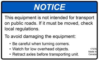
12 2. SAFETY WESTFIELD - MK FLEX AUGER 2.6. TRANSPORT & PLACEMENT SAFETY TRANSPORT & PLACEMENT SAFETY Transport auger in full down position with slight tension on cable. Properly place hitch pin and securely attach safety chain. Use a type of hitch pin that will not allow auger to separate from towing vehicle. Always attach an SMV (slow moving vehicle) sign before transporting auger. Equip the auger with the necessary lights for transportation where required by law. Always use hazard warning flashers on the tractor/towing vehicle when transporting, unless prohibited by law. Always travel at a safe speed, never exceeding 15 mph (24 km/hr). Reduce speed on rough surfaces and be cautious when turning corners or meeting traffic. Before raising/lowering/ moving the auger, make HAZARD AREA! KEEP OUT ELECTRO- CUTION HAZARD KEEP AWAY sure the area around the auger is clear of obstructions and/or untrained personnel. Never allow anyone to stand on or beneath auger while transporting or placing auger. Do not transport auger on slopes greater than 20. Wheels must be free to move when raising or lowering auger. Never attempt to move auger manually. To do so will result in serious injury. Before moving auger, check for overhead obstructions and/or electrical wires. Electrocution can occur without direct contact. Disconnect PTO driveline from tractor before moving auger or tractor, and secure driveline in transport saddle (where applicable). Raise intake feed hopper into transport position and lock hopper lift winch before transporting or moving auger. Intake feed side of hopper must face main auger when in transport position. Do not operate auger with intake hopper in transport position. This will cause damage to the u-joint R5
13 WESTFIELD - MK FLEX AUGER 2. SAFETY MAINTENANCE SAFETY Important: Not intended for transport on public roads. If auger must be moved, check local length and width regulations. Be careful when turning corners. Watch for low overhead objects. Retract axles before transporting unit. The Flex Auger exceeds hitch weight and/or towing capacity for some trucks and must be towed with appropriate equipment. A tractor is recommended. Refer to the Specifications Section in the Appendix for details on the weight of this machine. Check with your local dealer if you are unsure MAINTENANCE SAFETY Shut down and lock out all power before attempting maintenance of any kind. If applicable, disconnect PTO driveline from tractor or hydraulic hoses on units with hydraulic drive hoppers. After maintenance is complete, replace and secure all safety guards and safety devices, and if applicable, service doors and cleanout covers. Support auger tube before attempting maintenance on the undercarriage assembly. Auger should be in full down position for maintenance. Use only genuine Westfield replacement parts or equivalent. Replacement parts such as intake guards, pulley guards, PTO driveline shields, winches, and lift cables must meet ASABE standards or serious injury may result. Use of unauthorized parts will void warranty. If in doubt, contact Westfield or your Westfield dealer. Do not modify any auger components without authorization from Westfield. Modification can be dangerous and result in serious injuries SAFETY DECALS Keep safety decals clean and legible at all times. Replace safety decals that are missing or have become illegible. See decal location figures that follow. Replaced parts must display the same decal(s) as the original part. Safety decals are available from your distributor, dealer, or factory DECAL INSTALLATION 1. Decal area must be clean and dry, with a temperature above 50 F (10 C). 2. Decide on the exact position before you remove the backing paper. 3. Align the decal over the specified area and carefully press the small portion with the exposed sticky backing in place. 4. Slowly peel back the remaining paper and carefully smooth the remaining portion of the decal in place. 5. Small air pockets can be pierced with a pin and smoothed out using the sign backing paper R5 13

14 2. SAFETY WESTFIELD - MK FLEX AUGER 2.8. SAFETY DECALS SAFETY DECAL LOCATIONS Replicas of the safety decals that are attached to the equipment are shown in the figure(s) that follow. Proper safety procedures require that you familiarize yourself with the various safety decals and the areas or particular functions that the decals apply to, as well as the safety precautions that must be taken to avoid serious injury, death, or damage. * Westfield reserves the right to update safety decals without notice. Safety decals may not be exactly as shown. Figure 2.2 SA Flex 111 DECAL #17698 DECAL #28615 DECAL # NOTE: THE PLACEMENT OF THIS DECAL VARIES DEPENDING ON AUGER MODEL. Figure R5


15 WESTFIELD - MK FLEX AUGER 2. SAFETY SAFETY DECALS DECAL #17093 DECAL #17101 PLACED ON MACHINE BEHIND GUARD DECAL #17098 DECAL #27709 Figure R5 15


16 2. SAFETY WESTFIELD - MK FLEX AUGER 2.8. SAFETY DECALS DECAL #17099 DECAL #17096 DECAL #17398 DECAL #17113 DECAL #17378 DECAL #19960 DECAL #17107 DECAL #17531 DECAL # DECAL #18859 DECAL #17377 SA 111 ONLY DECAL #17101 DECAL # Figure 2.5 Important: Please review the decals shown. If your auger does not have these decals, they are available upon request. Please specify which decals you need R5


17 WESTFIELD - MK FLEX AUGER 2. SAFETY SAFETY DECALS DECAL # DECAL # DECAL # DECAL # DECAL # DECAL # SA 111 ONLY DECAL # DECAL # DECAL # R5 17


18 2. SAFETY WESTFIELD - MK FLEX AUGER 2.8. SAFETY DECALS DECAL # DECAL # DECAL # DECAL # DECAL # DECAL # DECAL # DECAL # DECAL # R5
19 WESTFIELD - MK FLEX AUGER 3. ASSEMBLY TUBES & FLIGHTING 3. Assembly WARNING Before continuing, ensure you have read and understand the relevant information in the safety section. Safety information is provided to help prevent serious injury, death, or property damage. Important: Before beginning assembly, familiarize yourself with all the sub-assemblies and hardware for the auger. Have all parts on hand and arrange them for easy access. Carry out assembly in a large, open area with a level surface. Always have 2 or more people assembling the equipment. Because of the weight, do not attempt assembly alone. Augers are available in various combinations. In most cases, the following instructions will apply to all augers. Where the assembly information varies, additional instructions will be included, indicated by an arrow. Before assembling, please check with the customer if they prefer the swing auger on the right or left side of the auger TUBES & FLIGHTING Note: When assembling more than 2 sections, start from spout end and work towards hopper. 1. Position tube sections. Align tube sections on a flat surface or on a series of benches. See Figure 3.24 for the 71, 81 and 91 and Figure 3.26 for the 91 and 111. WARNING After positioning tube sections, block them to prevent rolling or dropping. Damage to equipment or personal injury will result. The 71 has 3 tubes; from spout: 240 (6.10 m), 240 (6.10 m), and 208 (5.28 m) long. The 81 has 4 tubes; from spout: 240 (6.10 m), 240 (6.10 m), 240 (6.10 m), and 88 (2.24 m) long. The 91' has 4 tubes; from spout: 240 (6.10 m), 240 (6.10 m), 240 (6.10 m), and 208 (5.28 m) long. The 111 has 5 tubes; from spout: 240 (6.10 m), 240 (6.10 m), 240 (6.10 m), 240 (6.10 m), and 208 (5.28 m) long. 2. To attach lift cylinders, rotate appropriate tube so track is facing upward as shown in Figure 3.1. a. Attach the lift cylinders to the attach brackets as shown in Figure 3.1 using 7/16 x1-1/4 bolts and locknuts. outside tabs use regular bolts R5 19
20 3. ASSEMBLY WESTFIELD - MK FLEX AUGER 3.1. TUBES & FLIGHTING Only for 71 /81 : inside tabs use regular bolts. Only for 91 /111 : inside tabs use bolts with extension rods welded to head. b. Only for 81 /91 /111 : Slide the lift ram guide onto track on tube, then insert ram ends into brackets on guide (Figure 3.1). Secure with two roll pins. c. Return this tube section to the track down position. 81, ONLY 91 AND 111 ONLY 71 AND 81 - USE REGULAR 7/16 X 1-1/4 BOLTS 81, ONLY Figure Slide lower flight shaft onto upper flight shaft until flight ends butt together and flighting spiral matches up (Figure 3.2). Secure with hardware in Table 3.1. Repeat, if necessary, for any remaining flight shafts. Table 3.1 Details for fastenings: a For Flighting Qty For Tubes Qty 5/8 x 4-1/2 GR8 bolts and locknuts Track End (91 and 111 only) 5/8 x 2-3/4 GR8 bolt and locknut a. Quantity listed is per tube connection /16 x 1-1/4 GR8 bolts and locknuts 1/2 x 1-3/4 GR8 bolts and locknuts (2 top and 2 bottom) 12 4 Figure Slide tube sections together and secure. Make sure upper and lower track ends are aligned, and then tighten bolts. Secure with hardware in Table 3.1. Important: Do not connect lower auger tube to mid auger tube at this point! (Figure 3.4) R5
. 7. Lift the flex frame up underneath the lower tube and secure on benches. 8.")
21 WESTFIELD - MK FLEX AUGER 3. ASSEMBLY TUBES & FLIGHTING and 111 only: Bolt the track ends together (Figure 3.3). 6. Adjust lower auger tube out until it is flush with the flight shaft end (see Figure 3.4). 7. Lift the flex frame up underneath the lower tube and secure on benches. 8. Push the flex frame toward the spout to slide the auger flight through the front of the flex frame boot. Figure and 111 only MID-AUGER TUBE FLIGHT SHAFT END TUBE SUPPORT CLAMP 5/8 X 2-1/4 BOLTS AUGER FLIGHT SPOUT ALIGN END OF TUBE WITH END OF FLIGHT SHAFT. FLEX FRAME FLEX FRAME BOOT 5/8 LOCKNUTS LOWER AUGER TUBE 7/16 X 1-1/4 GR8 BOLTS LIFT FLEX FRAME UP INTO PLACE. SLIDE BACK SO TUBES CONTACT ONE ANOTHER. NOTE: Tubes may not be exactly as illustrated. Figure 3.4 Important: Important: 9. Connect flex frame assembly to lower auger tube flange with twelve 7/16 x 1-1/4 GR8 bolts and locknuts. 10. Secure tube support clamp to tube with eight 5/8 x 2-1/4 GR8 bolts and locknuts. Steps 11. to 20. must be completed in the order listed to prevent premature failure of the lower bearing. Refer to Figure Slide lower bearing onto flight stub and secure boot loosely with four 5/8 x 1-3/4 bolts and 5/8 locknuts. 12. Loosen setscrew on lock collar and slide it onto the lower flight. Leave lock collar loose for now. Grease zerk should be located on left side of bearing. 13. Seat flight shaft shoulder against washer and lower bearing, see Figure 3.6. Do not tighten bearing bolts until after step R5 21


22 3. ASSEMBLY WESTFIELD - MK FLEX AUGER 3.1. TUBES & FLIGHTING Now, slide the middle and lower tube sections together and secure with twelve 7/16 x 1-1/4 bolts and locknuts Only: Attach track clamp to tube with three 1/2 1/2 LOCKNUT locknuts. TRACK CLAMP Figure MK Flex Track Clamp 3/8 X 2-1/4 BOLT ADD SHIMS AS REQUIRED TO LEVEL DRIVESHAFT END PLATE 1-3/4 WOODEN BEARING CHAIN COUPLER 3/8 X 2-1/4 BOLT 3/8 X 1-3/4 SQUARE KEY WIDE RIM FLAT WASHER ROLLER CHAIN ROLLER CHAIN 3/8 X 2-1/2 ROLL PIN UPPER DRIVESHAFT 3/8-3-1/2 SQUARE KEY 5/8 LOCKNUTS 3/8 X 2-1/2 ROLL PIN THROUGH THIS HOLE IN LOWER FLIGHT STUB SHAFT 5/8 LOCKNUT LOWER BEARING UPPER BEARING & SPROCKET CHAIN TIGHTENER SPROCKET FLEX FRAME BOOT CHAIN TIGHTENER 5/8 X 1-3/4 BOLTS LOWER FLIGHT SHAFT NOTE: GREASE ZERK TO LEFT SIDE SPROCKET COVER Figure 3.6 FLEX FRAME LOWER DRIVESHAFT GUARD R5
23 WESTFIELD - MK FLEX AUGER 3. ASSEMBLY TUBES & FLIGHTING Note: 16. Install 3/8 x 3-1/2 square key and slide lower sprocket onto lower flight shaft. 17. Align upper sprocket with lower sprocket and chain tensioner sprocket using straight edge, then tighten setscrews and locking collar on upper bearing. 18. Loosen chain tightener sprocket and install roller chain on upper and lower sprockets. Secure with connecting link and clip. 19. Oil chain lightly and tension. 20. Tighten 5/8 locknuts on the lower bearing. Tighten collar on lower bearing and tighten setscrew. 21. Install two sections of lower driveshaft guard as well ad the driveshaft guard extension with 3/8 x 1 carriage bolts and 3/8 x 1 bolts and flange nuts. Tighten the guard extension and lower half of the guard. Leave the top half hand tight until the two piece chain guard is in place. Figure 3.6. The driveshaft ends are different. Make sure the end with the hole is at the lower end of the flex frame. 22. Place bracket under middle of driveline with spacer and use shims provided to level. 23. To install chain coupler (shipped assembled): a. On the two half-sprockets: check to make sure the keyways are NOT lined up. If they are, disassemble the chain coupler and offset the keyways, then reassemble. b. Slide the chain coupler onto the lower flight stub shaft, and attach it using 3/8 x 2-1/2 roll pin. c. Install the 3/8 x 1-3/4 square key onto the solid driveshaft, and slide the driveshaft into the opposite end of the chain coupler. Slide it in 1-3/4, until the end of the driveshaft is flush with the end of the sprocket. d. Secure both sides of the chain coupler using the setscrews; tighten securely. e. Disassemble the 1-3/4 wooden bearing (as supplied). Re-assemble the bearing around the solid driveshaft, and attach it to the frame using two 3/8 x 2-1/4 bolts and locknuts provided. Use shims as necessary; wood bearing is there for support only, DO NOT force shims into place. Once satisfied with driveline alignment, tighten bolts and locknuts securely R5 23
24 3. ASSEMBLY WESTFIELD - MK FLEX AUGER 3.1. TUBES & FLIGHTING DRIVESHAFT SHIELDS FLEX FRAME BOOT SMS #14 X 5/8 WITH WASHERHEAD DRIVESHAFT SHIELD STRAP 5/8 X 1-3/4 BOLTS LOWER FLIGHT SHAFT SPROCKET COVER FLEX FRAME 5/8 LOCKNUTS Figure 3.7 LOWER DRIVESHAFT GUARD 3/8 X1 CARRIAGE BOLTS 24. Secure the driveshaft to the front plate of the flex frame with a 1-3/4 bearing and flange and four 5/8 x 1-3/4 bolts and locknuts. Secure lower driveshaft with locking collar and setscrew. 25. Grease zerk should be located on left side of bearing. 26. Attach sprocket covers to flex frame boot with four 5/16 x 3/4 bolts and locknuts 27. Place two 60 and one 48 driveline guards over shaft and secure to flex frame with driveshaft shield straps and SMS #14 x 5/8 with washerhead R5
25 WESTFIELD - MK FLEX AUGER 3. ASSEMBLY DISCHARGE SPOUT & THRUST ADJUSTER 3.2. DISCHARGE SPOUT & THRUST ADJUSTER Attach discharge spout with 7/16 x 1-1/4 bolts and locknuts. The thrust adjuster is designed to transfer some pressure from the lower flight bearing to the upper flight bearing. Remove cover and 5/8 whiz nuts. Loosen the set screw on the lock collar and disengage the lock collar from the bearing to allow free movement of the flight shaft. Turn the 1-1/2 nut until it is snug against the bushing, then turn it so that the flight shaft moves an additional 1/4 (0.64 cm). Secure the lock collar and tighten the set screw. Re-install the cover over the two longer 5/8 bolts. Secure with two 5/8 whiz nuts R5 25
26 3. ASSEMBLY WESTFIELD - MK FLEX AUGER 3.3. FLEX FRAME COMPONENTS FLEX FRAME COMPONENTS ROLLER SUPPORT RIGHT OUTRIGGER LEG TRANSPORT REST 1/2 LOCKNUT 5/16 X 3/4 BOLT 1/2 LOCKNUT SPROCKET GUARD 1/2 X 2 X 3-1/4 U-BOLT 1/2 X 2 X 3-1/4 U-BOLT 5/16 X 3/4 BOLT 5/16 LOCKNUT 1/2 X 1-1/2 CARRIAGE BOLT LEFT OUTRIGGER LEG Figure 3.8 Important: 1. Install outrigger legs. Insert 1/2 x 1-1/2 carriage bolts pointing inward to prevent interference with hydraulic cylinder. There is a left and a right outrigger leg. Ensure they are installed with ports facing the discharge. 2. Place roller support inside key stops on flex frame, see Figure 3.8. The four 1/2 x 2 x 3-3/4 u-bolts are attached around the upright tubes, as shown in Figure 3.8. Ensure that these u-bolts are tightened securely. 3. Install sprocket guard on boot with four 5/16 x 3/4 bolts. Ensure that tabs on 2 piece sprocket guard are fit into the slots on either side of the lower guard. Tighten the top half of the lower guard. 4. Attach the transport rest to flex frame with four 1/2 X 2 x 3-1/4 u-bolts and locknuts. Leave flex tube support transfer rest untightened until after the flex tube is installed FLEX TUBE ASSEMBLY Complete assembly in the order listed to prevent premature failure of the lower bearing. Refer to Figure 3.9 to R5

27 WESTFIELD - MK FLEX AUGER 3. ASSEMBLY FLEX TUBE ASSEMBLY Note: Important: 1. Attach boot spinner plates. a. Insert plates between boot spinner and upper flex tube bundle. b. Mount onto the four 7/16 x 1-3/4 bolts welded to the tube. c. Fasten with 7/16 locknuts and 7/16 washers. d. Do not tighten all the way. e. Ensure boot is angled on the same side as swing tube is to be installed. f. Secure with eight 7/16 x 1-1/4 bolts with locknuts and washer. Flex boot can be rotated to the left or the right side of the auger. Figure 3.10 and 3.11 show setup for swing on right side of the auger, as viewed from the intake end facing toward the spout. To install the flex boot on left side, rotate boot to left side Figure Place 1-3/4 wide rim washer and 1-3/4 bearing and flange on flight shaft with 5/8 x 1-3/4 bolts and locknuts. Do not tighten until Step 5. Grease zerk should be located on left side of bearing. 3. Install square key and slide lower sprocket onto flight shaft. 4. Align lower sprocket with upper sprocket using straight edge, then tighten set screws. 5. Install roller chain on sprockets and adjust tension to about 1/4 (0.64 cm) deflection. Tighten the 4 bolts on lower bearing and secure lock collar. Oil chain lightly. 6. Bolt chain guard on boot Figure 3.10 BOOT SPINNER PLATE ROTATE FLEX BOOT AS SHOWN BY ARROW FOR LEFT SIDE USE 7/16 WASHERS & LOCKNUTS 7/16 X 1-1/4 BOLTS with four 5/16 x 3/4 bolts and locknuts. 7. Bolt half band and pivot support together with 7/16 x 1-1/4 bolts and locknuts on flex tube, 24 (61.0 cm) from spout plate. See Figure R5 27
28 3. ASSEMBLY WESTFIELD - MK FLEX AUGER 3.4. FLEX TUBE ASSEMBLY /16 X 1-1/4 BOLT 9 HALF BAND PIVOT SUPPORT 7/16 LOCKNUTS FLEX TUBE SPOUT PLATE ROLLER CHAIN 7/16 X 1-1/4 BOLT FLIGHT SHAFT 3/8 X 3-1/2 SQUARE KEY LOWER SPROCKET NOTE: GREASE ZERK TO LEFT SIDE UPPER SPROCKET FLEX BOOT CHAIN GUARD 5/16 X 3/4 BOLT LOWER SPROCKET 1-3/4 WIDE RIM WASHER 1-3/4 BEARING & FLANGE Figure R5
29 WESTFIELD - MK FLEX AUGER 3. ASSEMBLY CONNECTING FLEX TUBE TO FLEX FRAME 3.5. CONNECTING FLEX TUBE TO FLEX FRAME Important: 1. Place wide rim flat washer and 1/4 x 1-1/4 key on the gearbox shaft. 2. Place upper flex tube on flex frame as shown aligning u-joint in flex tube spout on the gearbox in the boot. 3. Place 6 galvanized spacers (4 in front, 2 in back) and 2 pivot plates on flex frame boot. Secure flex spout on flex frame with 7/16 x 1-3/4 bolts and locknuts. Upper plate has grease nipples on it; the lower plate does not. Grease nipples are in bolt bag and need to be installed. Pivot plates must be installed as illustrated. 4. Install 2-1/2 x 16 cylinder to flex spout and cylinder bracket as shown in Figure Use two 1/4 x 1-3/4 cotter pins to assemble cylinder pin and use snap rings provided to assemble clevis pin. FLEX SPOUT CYLINDER BRACKET FLEX TUBE HYDRAULIC CYLINDER 2-1/2 X 16 UPPER PIVOT PLATE WITH GREASE FITTINGS 7/16 LOCKNUT FLEX TUBE BOOT TWO GALVANIZED SPACERS FLEX TUBE SUPPORT FLEX FRAME SPRING PIN LOWER PIVOT PLATE FLEX FRAME BOOT 7/16 X 1-3/4 BOLT AND 7/16 FLAT WASHER GEARBOX SHAFT WIDE RIM FLAT WASHER, AND 1/4 X 1-1/4 KEY FOUR GALVANIZED SPACERS Figure R5 29
. Tighten u- bolts and locknuts and secure. See Figure 3.13.")

30 3. ASSEMBLY WESTFIELD - MK FLEX AUGER 3.6. TRACK SHOE, TRACKSTOP, & LIFT-ASSIST ARM (71 81 ) Adjust the position of the flex tube support, so that the lock pin sticks through the transport latch approximately 1/16 (1.6 mm). Tighten u- bolts and locknuts and secure. See Figure TRANSPORT LATCH LOCK PIN 6. Use a hoist to lift the lower end of flex tube slightly and adjust the position of the pivot roller with the 1/2 x 2-1/2 adjustment bolts to carry the weight of the flex tube. See Figure Figure 3.13 Figure 3.14 NOTICE Failure to lift the flex tube when adjusting the pivot roller can result in damage to the roller and/or flex tube TRACK SHOE, TRACKSTOP, & LIFT-ASSIST ARM (71 81 ) Auger MK Flex 71 MK Flex 81 Track Stop 2nd set of holes from top set of 8 holes grouped together : Slide the double roller track shoe onto track with cable attach-rod towards auger intake (Figure 3.15). Attach the angle trackstop as shown in Figure 3.16 using four 7/16 x 1-1/4 bolts and locknuts : Slide the four roller track shoe onto track (Figure 3.17). Attach angle track stop with eight 7/16 x 1-1/4 GR8 bolts and locknuts (Figure 3.18) R5
31 WESTFIELD - MK FLEX AUGER 3. ASSEMBLY TRACK SHOE, TRACKSTOP, & LIFT-ASSIST ARM (71 81 ) SPOUT Figure INTAKE Figure /16 X 1-1/4 GR8 BOLTS & LOCKNUTS Figure Figure Slide track shoe along full length of track to make sure there is no binding and that track ends are properly aligned : Attach the liftassist arm to the WASHER 1 LOCKNUT 1 FLAT center hole on the track shoe with an 11/16 short spacer and 1 flat washer on each side and a 1" x 10" bolt and locknut. Tighten securely (Figure 3.19). 11/16 SHORT SPACER 1 X 10 BOLT Figure R5 31
32 3. ASSEMBLY WESTFIELD - MK FLEX AUGER 3.7. TRACK SHOE, TRACKSTOP, & LIFT-ASSIST ARM ( ) TRACK SHOE, TRACKSTOP, & LIFT-ASSIST ARM ( ) 1. Slide the four-roller track shoe onto the track on the tube. See Figure Attach the trackstop to the upper end of the track on the auger tube with eight 7/16 x 1-1/4 GR8 bolts and locknuts. See Figure The 91' auger trackstop should be 132" from intake end of the upper middle tube, while the 111' trackstop should be 59-1/2 from intake end of the upper middle tube (Figure 3.20). Figure Slide the track shoe along the full length of track to make sure there is no binding and that track ends are properly aligned. Adjust tube joints if necessary (Figure 3.21). 4. Attach the lift-assist arm to center hole on track shoe with an 11/16 short spacer and 1 flat washer on each side, and a 1" x 10" bolt and locknut (see Figure 3.36 on page 47). Tighten securely. Figure ADJUSTABLE TOWBAR Important: The Flex has an adjustable towbar. The towbar is installed as seen in Figure Insert the adjustable towbar into the boot channel. Secure by placing a 3/4 x 6-1/2 long bolt and locknut through the back hole in the boot channel, under the flex frame. 2. Insert a 5/8 x 4-1/2 long bolt and locknut vertically into the hole at the front of the boot so that the towbar comes straight out from the flex frame. This bolt must be inserted from the bottom with the nut on top. Adjust the towbar if a speed-reducing gearbox is used with the system. In this case, the towbar is extended and pinned on an angle using the vertical bolt. This will line up the PTO with the PTO connection on the gearbox R5
33 WESTFIELD - MK FLEX AUGER 3. ASSEMBLY TRUSS (71 81 ) 3. Install the PTO cradle bracket on the front plate of the flex frame. Attach bracket with two 7/16 x 1-1/4 bolts and locknuts. PTO CRADLE BRACKET 5/8 X 4-1/2 BOLT & LOCKNUT ADJUSTABLE TOWBAR 3/4 X 6-1/2 BOLT & LOCKNUT BOOT CHANNEL Figure TRUSS (71 81 ) Note: Note: Important: See Figure 3.23 and Figure 3.23 is shown only to illustrate components and is not an exact representation of the 71 or 81 Flex Auger. See Figure 3.24 for correct cable location. Two 3/8 cable clamps per side of each cable are supplied to secure truss cables to the eyebolts as described below. All other locations require 5/16 cable clamps. 1. Fasten 2 standard truss support brackets to the correct position on the auger tubes with two 7/16 x 1-1/4 bolts and locknuts for each (Figure 3.24). 2. Fasten a high truss support bracket between the 2 standard truss support brackets with two 7/16 x 1-1/4 bolts and locknuts (Figure 3.23,and 3.24). 3. Attach eyebolt to one end of truss cable with two 3/8 cable clamps. Insert eyebolt into lower truss anchor and thread on nut a short way. 4. Pull truss cable over truss support brackets, around upper truss anchor bracket and back over truss support brackets to lower truss anchor, holding it loosely in place with one 5/16 cable clamp at upper truss anchor on each truss support bracket. Do not tighten cable clamps at this time. 5. Place other eyebolt onto lower truss anchor and thread on nut a short way. 6. Insert other end of truss cable through this eyebolt. Pull out all slack and secure with two 3/8 cable clamps R5 33
34 3. ASSEMBLY WESTFIELD - MK FLEX AUGER 3.9. TRUSS (71 81 ) Important: Important: 7. The upper end of all augers should have an upward bow before being placed on the transport undercarriage (auger tube will straighten when fully assembled). Place supports under the discharge end until upward bow is correct. The upward bow should be about 5" (12.7 cm) on the 71 auger, and 6-7 (15.2 cm cm) on the 81 auger. 8. Tighten eyebolts to take remaining slack out of truss cable and to maintain the appropriate upward bow. After tension is adjusted, tighten cable clamps on truss support brackets and upper truss anchor. Check for proper side alignment. Once auger is fully assembled, adjust truss cables on all units (because of initial stretching). Cables may also require adjustment for side alignment. 9. Lower Truss Support of 81 (Figure 3.23 and 3.24): a. Fasten short truss anchor to lower auger tube with 7/16 x 1-1/4 bolts and locknuts. b. Fasten high truss support bracket to mount on bottom of center tube with 7/16 x 1-1/4 bolts and locknuts. c. Attach eyebolt to one end of truss cable with two 3/8 cable clamps, then insert eyebolt into short truss anchor and thread on nut a short way. d. Pull truss cable over bottom high truss support bracket, around upper truss anchor bracket and back over high truss support bracket to short truss anchor, holding it loosely in place with one 5/16 cable clamp (on each side) at upper truss anchor and two 5/16 cable clamps at truss support bracket. e. Place other eyebolt into short truss anchor and thread nut on a short way. f. Insert other end of truss cable through this eyebolt. Pull out all slack and secure with two 3/8 cable clamps. g. Tighten eyebolt to take remaining slack out of truss cable and adjust tension to keep auger tube straight. Tighten cable clamps on truss support bracket and upper truss anchor. Once auger is fully assembled, adjust truss cables (because of initial stretching). Cables may also require adjustment for side alignment R5
35 WESTFIELD - MK FLEX AUGER 3. ASSEMBLY TRUSS (71 81 ) TRUSS CABLE STANDARD TRUSS SUPPORT BRACKET HIGH TRUSS SUPPORT BRACKET STANDARD TRUSS SUPPORT BRACKET 7/16 X 1-1/4 BOLTS & LOCKNUTS 5/16 CABLE CLAMPS 3/8 CABLE CLAMP UPPER TRUSS ANCHOR BRACKET WITH 5/16 CABLE CLAMP LOWER TRUSS ANCHOR EYEBOLT NOTE: PARTIAL 81 TRUSS ASSEMBLY SHOWN Figure 3.23 Truss Components Figure 3.24 Flex 71 & 81 Auger Complete Truss Layout R5 35
36 3. ASSEMBLY WESTFIELD - MK FLEX AUGER TRUSS ( ) TRUSS ( ) Note: Note: When assembling the truss system, do not tighten any bolts until all components are in place. Refer to Figure 3.25 on page 37 for correct positioning of the truss components. 1. Loosely attach the 2 low pairs of truss towers (D) and 57 (111') high pairs of truss towers (C) to the truss-attach brackets welded to auger tube with 7/16 x 1-1/4 bolts and locknuts. 2. Loosely join the ends of two 10' (3.05 m) truss tubes (A) and two crossbrace tubes (B) between the top end of each pair of high truss towers using 1/2 x 2-3/4 bolts and locknuts. 3. Thread a 3/4 nut onto each adjust-tube, then insert threaded end into trussanchors on lower and upper auger tubes. Join the adjust tubes (E) and 10' truss tubes (A) at the two low (D) truss towers with 1/2 x 2-3/4 bolts and locknuts. A single crossbrace tube is positioned between the low (D) truss towers and adjacent high (C) truss towers. 4. Loosely join all the crossbrace tubes to tabs welded to top of truss-attach brackets using 1/2 x 1-1/2 bolts and locknuts. Attach these tubes to same side of tab as they are attached to the truss tower. 5. Tighten all bolts and nuts. 6. Install the 5 (111') pairs of x-clamps where the crossbrace tubes meet with two 7/16 x 1" bolts and locknuts on each. 7. Thread a second 3/4 nut on the end of the adjust tube, then adjust the threaded adjust tubes until upper and lower auger tubes have a slight upward bow. Lock the adjust nuts against bracket R5
37 WESTFIELD - MK FLEX AUGER 3. ASSEMBLY TRUSS ( ) Figure R5 37
38 3. ASSEMBLY WESTFIELD - MK FLEX AUGER TRUSS ( ) CABLE TRUSSING ( ) 1. Attach an eyebolt to one end of each of two truss side cables with two 3/8 cable clamps using about 10 (25.4 cm) to 12 (30.5 cm) of cable. Tighten securely (Figure 3.26). 2. Insert eyebolts into tabs located on flex frame. Secure with 1/2 locknut (Figure 3.26). 3. Loosely attach the truss cables to each cable support arm with a 5/16 cable clamp as shown in Figure For 91 : Pull longer cable around truss cable anchor at top end of auger tube and loosely attach with a 5/16 cable clamp (Figure 3.27). 5. For 111 : Attach remaining eyebolts to adjust bracket and thread on 1/2 locknuts about 1/2 (Figure 3.26). 6. For 111 :Thread loose ends of the cable through each eyebolt, pull tight, then secure with two 3/8 cable clamps (Figure 3.26). Tighten securely. 7. Adjust tension of side truss cable by tightening the eyebolts at the adjust brackets. These cables must be very tight. Also adjust for side alignment. 8. Now tighten all of the cable clamps at cable supports and arms. ADJUST BRACKET(111 ) EYEBOLT ( cm) NUT 3/8 CABLE CLAMPS Figure Only R5
 5/8 x 1-1/2 BOLT AND LOCKNUT Figure 3.")
39 WESTFIELD - MK FLEX AUGER 3. ASSEMBLY TRANSPORT UNDERCARRIAGE (71 81 ) Figure TRANSPORT UNDERCARRIAGE (71 81 ) 5/8 x 1-1/2 BOLT AND LOCKNUT Figure 3.28 MK Flex R5 39
40 3. ASSEMBLY WESTFIELD - MK FLEX AUGER TRANSPORT UNDERCARRIAGE (71 81 ) Figure Note: 1. Fasten the lower reach arms to the axle with three 5/8 x 2" bolts and locknuts on each side : Attach long tubular crossmember to bottom of large frame brackets (Figure 3.28), with two 5/8 x 1-1/2 bolts and locknuts : Install 2 corner braces with 1/2 x 1-1/4 bolts and locknuts as seen in Figure Loosely attach short crossmember to small frame brackets with two 5/8 x 2" bolts and locknuts, sandwiching the flatbraces (B) between the short crossmember and small frame brackets on each side (Figure 3.32). Leave loose until step Secure the crossbraces to the welded tabs on the lower reach arms with four 1/2 x 1-1/4 bolts and locknuts, and a fifth bolt and locknut where the braces cross. Tighten securely : Insert axle extensions into axle and pin in place using a 3/8 x 5-1/2 pin and hair pin. 7. Wheel hub assembly: a. Remove any dirt or paint from spindle and hub. b. Thoroughly pack wheel bearings and cups with a good grade of bearing grease. c. Place large bearing into hub and carefully tap in seal. d. Slip hub onto spindle and insert small bearing. e. Tighten slotted spindle nut until hub drags slightly. Back off nut about 1/4 turn until hub turns freely. f. Install cotter pin and dust cap. Installing tires may not leave you with enough clearance to position and attach undercarriage once auger tube is raised. If so, install wheels after assembly is complete R5
41 WESTFIELD - MK FLEX AUGER 3. ASSEMBLY TRANSPORT UNDERCARRIAGE (71 81 ) g. Install 16 tires and rims provided on hubs. Check inflated according to recommendation on tire side-wall. Wheels may be mounted on hubs at this time with six 1/2 x 1-5/8 wheel bolts. 8. Fasten upper lift arms to lower reach arms using two short spacer bushings (3/4 long), flat washers, and 1" x Figure /2 bolts and locknuts. Tighten securely. Lift arms pivot on the spacer bushings (Figure 3.31). Figure Raise the discharge end of auger with a front end loader and a strong sling/chain or block and tackle. The height should be sufficient to clear undercarriage assembly. AUGER NOT EXACTLY AS SHOWN R5 41
42 3. ASSEMBLY WESTFIELD - MK FLEX AUGER TRANSPORT UNDERCARRIAGE (71 81 ) WARNING Do not remove tube support until the assembly in this section has been completed. Important: 10. Place undercarriage beneath tube assembly. 11. Position stabilizer braces (A) (Figure 3.32) and attach lower reach arms to bracket on tube with long spacer bushings (1-1/8 long), 1 flat washers, and 1" x 3-1/2 bolts and locknuts. Tighten securely. Reach arms pivot on the spacer bushings. Refer to Figure 3.32 for correct placement of lower reach arms. 12. Fasten flat braces (B) to first set of holes (furthest from intake) on stabilizer braces (A) with one 5/8 x 2" bolt and locknut. Place one 5/8 x 1-1/2 bolt and locknut in other hole of stabilizer brace : Attach the tubing crossbraces to the upper lift arms (Figure 3.32) by slipping the tube clamps over the flat pressed ends of the lift arms (where they are attached to the frame) and loosely attaching the tubing crossbraces using five 1/2 x 1-1/4 bolts and locknuts. Use a large c-clamp vise grip to squeeze and hold the tube clamps in position for attachment of the tubing crossbraces. Once in position, tighten these bolts. 81: Attach the tubing crossbraces to the upper lift arms using five 1/2 x 1-1/4 bolts and locknuts. The 81 auger does not use tube clamps. The attach tabs are welded onto the upper reach arms : Attach upper lift arms to track shoe. Use a short spacer bushing (3/4 long) and flat washer on both sides; insert the 1" x 10" bolt and tighten securely with locknut (Figure 3.32) : Attach upper lift arms to the center hole on the lift-assist arms as shown in Figure 3.36 using two 15/16 medium spacers, flat washers, and two 1 x 3-1/2 bolts and locknuts. Tighten securely. The lift arms will pivot on the spacer bushings. 16. Lower upper end of auger slowly until track shoe rests against upper track stop. The 81 lift-assist will rest against the track R5
43 WESTFIELD - MK FLEX AUGER 3. ASSEMBLY TRANSPORT UNDERCARRIAGE (71 81 ) Figure R5 43
44 3. ASSEMBLY WESTFIELD - MK FLEX AUGER TRANSPORT UNDERCARRIAGE ( ) TRANSPORT UNDERCARRIAGE ( ) Note: See Figure With arch on axle positioned as shown in Figure 3.33, fasten the lower reach arms to brackets on axle with four 5/8 x 2" bolts and locknuts on each side. See Figure Attach short crossmember loosely with two 5/8 x 2" bolts and locknuts, sandwiching flat braces (B) between crossmember and frame bracket. Do not tighten bolts until undercarriage is beneath tube assembly (Figure 3.35). 3. Secure the tubing crossbraces to welded lugs on lower reach arms with four 1/2 x 1-1/4 bolts and locknuts, plus a fifth bolt and locknut where the braces cross. On the 111' auger, add a tie tube between the bottom welded lugs. Use 1/2 x 1-3/4 bolts and locknuts. 4. Attach the corner braces on the 91' auger (axle crossbraces on the 111' auger) with two 1/2 x 1-1/4 bolts and locknuts each. 5. Insert axle extensions into axle and pin in place using a 3/8 x 5-1/2 pin and hair pin. 6. Wheel hub assembly: a. Remove any dirt from spindle and hub. b. Thoroughly pack wheel bearings and cups with a good grade of bearing grease. c. Place large bearing into hub and carefully tap in seal. d. Slip hub onto spindle and insert small bearing and washer. e. Tighten slotted spindle nut until hub drags slightly. Back off nut about 1/4 turn until hub turns freely. f. Install cotter pin and dust cap. Installing tires may not leave you with enough clearance to position and attach undercarriage once auger tube is raised. If so, install wheels after assembly is complete. g. Install the assembled tires and rims provided onto the hubs at this time using 6 wheel bolts.i 7. Fasten upper lift arms to lower reach arms using two 15/16 spacer bushings, flat washers, and 1" x 3-1/2 bolts and locknuts. Tighten securely; lift arms pivot on the spacer bushings (Figure 3.34). 8. Secure the tubing crossbraces to welded lugs on upper lift arms with four 1/2 x 1-1/4 bolts and locknuts plus a fifth bolt and locknut where the braces cross. On the 111' auger, add a tie tube between the bottom welded lugs as shown in Figure Use 1/2 x 1-3/4 bolts and locknuts R5
 111 ONLY (125 / 3.18 M LONG) 111 ONLY Figure 3.33 Figure 3.34 9. Lower auger intake to the ground.")
45 WESTFIELD - MK FLEX AUGER 3. ASSEMBLY TRANSPORT UNDERCARRIAGE ( ) 111 ONLY (120 / 3.05 M LONG) 111 ONLY (125 / 3.18 M LONG) 111 ONLY Figure 3.33 Figure Lower auger intake to the ground R5 45
46 3. ASSEMBLY WESTFIELD - MK FLEX AUGER TRANSPORT UNDERCARRIAGE ( ) Raise the upper end of auger with a block and tackle or a front-end loader. Securely attach a strong sling or chain about 36" (0.91 m) above trackstop. Secure tube to prevent it from turning while lifting. Raise sufficiently to clear undercarriage. AUGER NOT BE EXACTLY AS SHOWN WARNING Do not remove tube support until assembly in this section has been completed. 11. Place undercarriage beneath tube assembly. 12. Position stabilizer braces (A) (Figure 3.35) and attach lower reach arms to bracket on tube with long spacer bushings (1-1/8 long), flat washers, and 1" x 3-1/2 bolts and locknuts. Tighten securely. Reach arms pivot on the spacer bushings. 1-1/8 LONG SPACER SHORT CROSSMEMBER FLAT BRACES (B) 1 X 3-1/2 BOLT AND LOCKNUT Figure 3.35 FLAT WASHER STABILIZER BRACES (A) 5/8 X 1-1/2 BOLT & LOCKNUT 5/8 X 2 BOLT AND LOCKNUT R5
47 WESTFIELD - MK FLEX AUGER 3. ASSEMBLY LIFT CABLES 13. Fasten flat braces (B) to first set of holes (furthest from intake) on stabilizer braces (A) with one 5/8 x 2" bolt and locknut. Place one 5/8 x 1-1/2 bolt and locknut in other hole of stabilizer brace. 14. Attach upper lift arms to center hole on the liftassist arms (Figure 3.36) with two 15/16 medium spacers, flat Figure 3.36 washers, and two 1" x 3-1/2 bolts and locknuts. Tighten securely; lift arms will pivot on the spacer bushings. 15. Lower discharge end of auger slowly until track shoe rests against trackstop and the lift-assist arm rests against track LIFT CABLES Note: Determine right or left side of auger by standing at intake end facing top discharge end MK FLEX Secure the solid connector end of the short cylinder connector hydraulic hose to above elbow fitting on right side lift cylinder. Use thread sealant (not supplied). The other end of this short hose is secured later R5 47
48 3. ASSEMBLY WESTFIELD - MK FLEX AUGER LIFT CABLES Figure 3.37 CAUTION Track shoe must rest against track stop when adjusting cable. Failure to heed will allow auger to raise higher than designed to lift, resulting in damage to auger and injury to personnel. Note: Important: Although the lift cable is factory installed on the cylinder, make sure that the cable clamps on the cylinder are secure and the cables are properly seated in the cable sheaves before attaching the cable to the track shoe. 2. With both cylinders in full down position and track shoe resting against the track stop, thread both cables over the cable-attach-rod on the track shoe. Pull cable very tight, then secure with three 5/16 cable clamps on each cable, positioned as shown (Figure 3.38). Tighten securely. Tie up excess ends of lift cable with tape or ty-wrap. Figure 3.38 Lift cable will stretch with initial use. Check frequently and adjust R5

49 WESTFIELD - MK FLEX AUGER 3. ASSEMBLY LIFT CABLES 3. Attach the cable-roller to the appropriate location on lower end of the track with two 7/16 x 1-1/4 bolts and locknuts (Figure 3.39). Attach the cable-roller to lower end of track. Figure MK FLEX Important: Note: 1. Seat lift-assist arm against the track and place both lift cylinders in full down position (fully retracted). Lift cables may stretch with use. Check frequently and adjust when necessary. 2. Thread the lift cables over the respective pulleys on the lift-assist arm, pull cables tight, and secure with three 5/16 (3/8 on 111 ) cable clamps on each cable. Tighten securely. Do not crisscross cables (Figure 3.40). Although the lift cables are factory installed on the lift cylinders, make sure the cable clamps on the cylinders are secure and the cables are properly seated in the cable sheaves before attaching the cables to the lift-assist arm. Figure R5 49
50 3. ASSEMBLY WESTFIELD - MK FLEX AUGER HYDRAULIC HOSES HYDRAULIC HOSES CAUTION Track shoe must rest against track stop when adjusting cable. Failure to heed will allow auger to raise higher than designed to lift, resulting in damage to auger and injury to personnel. Note: Determine right or left side of auger by standing at intake end facing top discharge end MK FLEX 71 Note: Note: Elbow fittings are factory installed. Use thread sealant on fitting and hose threads (thread sealant not supplied.) 1. Rotate the elbow fitting at lower end of lift cylinder so it faces down, making sure it is securely tightened (Figure 3.37). 2. With elbow fitting on left side lift cylinder facing back as shown, secure the tee fitting to the elbow fitting (Figure 3.37). 3. Securely attach the swivel connector end of the short hydraulic hose to tee fitting on left side cylinder (Figure 3.37). Make sure that this short hose is beneath the lift cable on left side lift cylinder (Figure 3.41). Before attaching short connector hydraulic hose to left side lift cylinder, make certain lift cables are tightly stretched and that this hose is positioned beneath lift cable on left side lift cylinder (Figure 3.41). If lift cable is not installed above this hose, it could result in the hose wearing through during operation, causing a hazardous condition. WARNING Wear on hose can cause auger to drop suddenly, causing serious injury or death R5

51 WESTFIELD - MK FLEX AUGER 3. ASSEMBLY HYDRAULIC HOSES 4. Securely attach the 272 (6.91 m) long hydraulic hose to tee fitting (Figure 3.41). Place this hose into brackets welded to side of auger tube and boot. Bend tops of these brackets over slightly to hold hose in place. Important: Protect hose ends from dirt. Figure Recheck that bolts on undercarriage, lift cylinders, and cable clamps are tight, then remove auger tube support MK FLEX 81' Note: Note: Lower fittings refer to those closer to boot end of auger. Upper fittings refer to those closer to discharge end of auger. Use thread sealant (not supplied) on hydraulic connections. 1. Position both elbow fittings on right lift cylinder. The lower one should face forward and downward at approximately 45. The upper one should face rearward and downward at approximately 45 (Figure 3.42). Make certain they are tight. 2. Secure the solid connector end of the short (17" / 43.2 cm) cylinderconnector hydraulic hose to the lower elbow fitting. 3. Secure the solid connector end of the long (32" / 81.3 cm) cylinder-connector hydraulic hose to the right upper elbow fitting. Before attaching short connector 17 (43.2 cm) hydraulic hose to left side lift cylinder, make certain lift cables are tightly stretched and that this hose is positioned beneath lift cable on left side lift cylinder (Figure 3.37). With lift cable beneath this hose, cable will wear on hose as auger is raised and lowered, causing hose to wear through. WARNING Wear on hose can cause auger to drop suddenly, causing serious injury or death R5 51
52 3. ASSEMBLY WESTFIELD - MK FLEX AUGER HYDRAULIC HOSES Important: 4. Position the elbow fittings on the left lift cylinder. The lower one should face forward and downward at approximately 45. The upper one should face rearward and upward at approximately Secure the tee fittings to the left cylinder elbow fittings and position them as shown in Figure Make certain they are securely tightened. 6. Secure the swivel ends of the upper (32" / 81.3 cm) and lower (17" / 43.1 cm) cylinder-connector hoses to the tees as shown. 7. Check upper 32" (81.3 cm) cylinder-connector hose position to ensure there is 8-1/2 (21.6 cm) of clearance to lift cables as shown in Figure Attach the 272" (6.91 m) long pressure hydraulic hose with shut-off valve to the lower tee fitting (nearest auger intake). 9. Attach the 347" (8.81 m) return hydraulic hose without shut-off valve to the upper tee fitting (nearest auger discharge end). 10. Thread hoses through back arm attach bracket (Figure 3.42). 11. Place both hoses into retaining brackets welded to side of auger tube and boot. Bend tops of brackets over slightly to hold hoses in place. Protect hose ends from dirt. 12. Recheck that bolts on undercarriage, lift cylinders, and cable clamps are tight, then remove auger tube support. Figure 3.42 MK130 Plus R5
53 WESTFIELD - MK FLEX AUGER 3. ASSEMBLY HYDRAULIC HOSES MK FLEX Note: Note: Note: Right or left side of auger, as referred to in this section, is determined by standing at intake end facing top discharge end. Lower fittings refer to those closer to boot end of auger. Upper fittings refer to those closer to discharge end of auger. Use thread sealant (not supplied) on all hydraulic connections. 1. Position both elbow fittings on right cylinder. The lower one should face forward and downward at approximately 45. The upper one should face rearward and downward at approximately 45 (Figure 3.43). Make certain they are tight. 2. Secure the solid connector end of the short (17" / 43.3 cm) cylinderconnector hydraulic hose to the lower elbow fitting. 3. Secure the solid connector end of the long (32" / 81.3 cm) cylinder-connector hydraulic hose to the upper elbow fitting. Before attaching short connector hydraulic hose to left side lift cylinder, make certain lift cables are tightly stretched and that this hose is positioned beneath lift cable on left side lift cylinder (Figure 3.43). If lift cable is not installed above this hose, it could result in the hose wearing through during operation, causing a hazardous situation. WARNING Wear on hose can cause auger to drop suddenly, causing serious injury or death. Important: 4. Position the elbow fittings on the left cylinder. The lower one should face forward and downward at approximately 45. The upper one should face rearward and upward at approximately Secure the tee fittings to the left cylinder elbow fittings and position them as shown in Figure Make certain they are securely tightened. 6. Secure the swivel ends of the upper (32" / 81.3 cm) and lower (17" / 43.2 cm) cylinder-connector hoses to the tees as shown. 7. Check upper 32" (81.3 cm) cylinder-connector hose position to ensure there is 8-1/2 (21.6 cm) clearance to lift cables as shown in Figure Attach the 336" (8.53 m) long (91 ) or 392" (9.96 m) long (111 ) pressure hose with shutoff valve to the lower tee fitting (nearest auger intake). 9. Attach the 403" (10.2 m) long (91 ) or 473" (12.0 m) long (111 ) return hose without shutoff valve to the upper tee fitting (nearest auger discharge end). 10. Thread hoses through back arm attach bracket as shown in Figure Place both hoses into retaining brackets welded to side of auger tube and boot. Bend tops of brackets over slightly to hold hoses in place. Protect hose ends from dirt. 12. Recheck that bolts on undercarriage, lift cylinders, and cable clamps are tight, then remove auger tube support R5 53
54 3. ASSEMBLY WESTFIELD - MK FLEX AUGER PTO (CV) DRIVELINE Figure PTO (CV) DRIVELINE Important: 1. Clean PTO driveline and drive shaft ends of any paint or dirt. Ensure that a 3/8 x 3-1/2 square key is installed in the drive shaft before attaching PTO driveline. 2. Slide plain end of PTO driveline onto drive shaft. Make sure that the holes for the 3/8 roll pin are lined up and square key is in place. 3. Making sure eyes are protected, carefully tap in roll pin. Tighten set screw. 4. Slide PTO transport saddle through support strap on boot and rest PTO driveline in it until connected to tractor R5
55 WESTFIELD - MK FLEX AUGER 3. ASSEMBLY LOW PROFILE HOPPER Figure LOW PROFILE HOPPER Note: 1. Attach the pivot-connector to the top hole in hopper with two 5/8 x 1-1/2 bolts and locknuts. Do not over-tighten. Tighten snug only; these bolts act as pivot points (Figure 3.46). 2. Loosely secure service door with 2 square latch-washers and 3/8 locknuts. Do not tighten until hopper assembly is completed. 3. Clean dirt from inside u-joint on hopper and flight shaft end, then insert Woodruff key, see Figure Raise and support hopper tube at about 59" (1.5 m) under spout. 5. Open service door on hopper, then bring tube and hopper together guiding flight shaft into u-joint. 6. Secure tube to pivot-connector on hopper with twelve 7/16 x 1-1/4 bolts and locknuts R5 55
56 3. ASSEMBLY WESTFIELD - MK FLEX AUGER LOW PROFILE HOPPER FLIGHT SHAFT END Figure 3.45 U-JOINT 7/16 LOCKNUT 7/16 X 1-1/4 BOLTS HOLES FOR 5/8 X 1-1/2 BOLTS AND LOCKNUTS Figure Tighten set screws on u-joints, then close and secure the service door, tighten 3/8 locknuts and 3/8 square latch washers. 8. Remove the two 5/16 whiznuts that secure the chain drive guard. Attach the 2-piece rubber extension to inside of hopper lip with 5/16 x 3/4 bolts and whiznuts and the flat iron straps provided, plus the 2-piece extension connector plates. Replace bolts, see Figure Attach two swivel wheels to the two hopper corners with eight 3/8 x 1 carriage bolts and 3/8 whiz nuts (Figure 3.50) R5
57 WESTFIELD - MK FLEX AUGER 3. ASSEMBLY LOW PROFILE HOPPER STEERING ASSEMBLY Important: Hoppers can be set up for use on right or left side of auger. Figure 3.47 to 3.51 illustrate the right side as viewed when standing at the hopper looking toward the spout. Figure 3.52 to 3.55 illustrate the left side as viewed when standing at the hopper looking toward the spout. 1. Bolt short and long castor arms to hopper with four 3/8 x 1 bolts and 3/8 flange nuts for each arm (Figure 3.48 and 3.49). 2. Insert steering shaft and motor castors through bearings on each castor arm. Figure 3.48 Figure 3.50 Figure 3.49 Figure 3.47 Right Side Setup R5 57
58 3. ASSEMBLY WESTFIELD - MK FLEX AUGER LOW PROFILE HOPPER FOLDABLE HANDLE 3/8 X 2 BOLT 3/8 FLANGE NUT SPROCKET STEERING LINKAGE MOTOR CASTOR STEERING SHAFT STEERING COVER STEERING CHAIN SPROCKET 1/4 X 1 WOODRUFF KEY 5/16 WHIZNUT LONG CASTOR ARM 3/8 X 1 BOLT 3/8 FLANGE NUT Figure 3.48 Right Side Setup 5/16 WHIZ NUT STEERING STOP STEERING LINKAGE 7/16 LOCKNUT 3/8 FLANGE NUT STEERING ARM WELDMENT 7/16 X 1-1/4 BOLT SHORT CASTOR ARM NOTE: PORTS TO THIS SIDE 1/4 X 1 WOODRUFF KEY MOTOR CASTOR Figure 3.49 Right Side Setup 3/8 X 1 BOLT HYDRAULIC MOTOR 3/8 X 1-1/4 BOLT AND LOCKWASHER HOPPER DRIVE WHEEL 3/8 X 1 BOLT AND LOCKWASHER R5
59 WESTFIELD - MK FLEX AUGER 3. ASSEMBLY LOW PROFILE HOPPER 3/8 x 1 CARRIAGE BOLT 3/8 WHIZ NUT HOPPER SWIVEL WHEEL Figure 3.50 Right Side Setup STEERING STOP (UNDER SIDE) STEERING STOP Figure 3.51 Steering Stop Placement on Right Side Setup R5 59
60 3. ASSEMBLY WESTFIELD - MK FLEX AUGER LOW PROFILE HOPPER Figure 3.53 Figure 3.54 Figure 3.55 Figure 3.52 Left Side Setup R5
61 WESTFIELD - MK FLEX AUGER 3. ASSEMBLY LOW PROFILE HOPPER 3/8 FLANGE NUT FOLDABLE HANDLE 3/8 X 2 BOLT SPROCKET STEERING COVER STEERING SHAFT STEERING CHAIN SPROCKET 1/4 X 1 WOODRUFF KEY STEERING STOP 5/16 WHIZNUT STEERING LINKAGE MOTOR CASTOR LONG CASTOR ARM 3/8 FLANGE NUT 3/8 X 1 BOLT Figure 3.53 Left Side Setup STEERING LINKAGE STEERING STOP 5/16 WHIZ NUT STEERING ARM WELDMENT 7/16 LOCKNUT 7/16 X 1-1/4 BOLT 1/4 X 1 WOODRUFF KEY NOTE: PORTS TO THIS SIDE SHORT CASTOR ARM MOTOR CASTOR HOPPER DRIVE WHEEL 3/8 X 1 BOLT AND LOCKWASHER Figure 3.54 Left Side Setup 3/8 X 1-1/4 BOLT AND LOCKWASHER HYDRAULIC MOTOR 3/8 FLANGE NUT 3/8 X 1 BOLT R5 61
 STEERING STOP Figure 3.56 Steering Stop Placement on Left Side Setup 3.")

62 3. ASSEMBLY WESTFIELD - MK FLEX AUGER LOW PROFILE HOPPER HOPPER 3/8 X 1 CARRIAGE BOLT 3/8 WHIZ NUT SWIVEL WHEEL Figure 3.55 Left Side Setup STEERING STOP (UNDER SIDE) STEERING STOP Figure 3.56 Steering Stop Placement on Left Side Setup 3. Insert a sprocket on the steering shaft and on motor castor on the long castor arm (on side with steering assembly). Connect sprockets with steering chain and secure with connecting link and clip. 4. Place steering cover over chain and secure in place with eight 5/16 whiz nuts (one whiz nut on each side of cover, 4 places) R5

63 WESTFIELD - MK FLEX AUGER 3. ASSEMBLY LOW PROFILE HOPPER 5. Insert foldable handle over steering shaft; secure in place with a 3/8 x 2 bolt and 3/8 flange nut. See Figure 3.48 for right side setup or Figure 3.53 for left side setup. 6. Place steering stops on each steering shaft but do not tighten set screws until Step Slide steering arm weldments over motor castors, secure in place with 1/4 x 1 key. Tighten setscrews on each side. 8. Points A and B on steering arm weldments should point at main auger. See Figure 3.57 for right side set-up, and see Figure 3.58 for left side set-up. 9. Place steering linkage on A holes nearest hopper on steering arm weldments, see Figure 3.57, or Figure Adjustment is built into STEERING steering linkage to align tires LINKAGE parallel to each other if required. Secure with two 7/16 x 1-1/4 bolts and two 7/16 locknuts. Nuts should be tight enough to hold linkage in place but allow it to move easily when using the steering arm. 10. Insert hydraulic motors through motor castors and secure with 3/8 x 1-1/4 bolts and 3/8 lockwasher (4 bolts per motor). Ensure motor ports are installed towards swing spout, as shown in Figure 3.58 and or 3.53 and Place hopper drive wheels on hydraulic motor shafts, securing in place with 1/4 Woodruff key. Tighten setscrews. 12. Install hopper drive wheel on wheel hub with four 3/8 x 1 bolts and 3/8 lockwashers. 13. Once set up for right or left STEERING ARM WELDMENTS MAIN AUGER TUBE NOTE: THE STEERING ARM WELDMENTS MUST POINT TOWARD THE MAIN AUGER TUBE. Figure 3.57 Right Side Setup B STEERING ARM WELDMENT MAIN AUGER TUBE NOTE: THE STEERING ARM WELDMENTS MUST POINT TOWARD THE MAIN AUGER TUBE. Figure 3.58 Left Side Setup side use, turn handle so that wheels are 90 to the swing tube. Adjust position of stops so that wheels cannot be turned further and tighten set screws (Figure 3.51 for right-side setup, and Figure 3.56 for left-side set-up). Continue to turn handle to ensure full 90 range. B A STEERING LINKAGE R5 63

64 3. ASSEMBLY WESTFIELD - MK FLEX AUGER LOW PROFILE HOPPER ATTACHING SWING TO FLEX AUGER 1. Clean u-joint spline and lower gearbox spline, then apply a light film of grease on splined shaft. 2. Guide splined universal joint 3/8 X 3/4 BOLTS onto splined shaft as the intake hopper is lowered onto the boot. Once positioned, the swivel ring rests flat on the boot surface and inside TAB the four spacer nuts. 3. Install four spout head retainers and large boot BOOT retainer spacers (galvanized) with 3/8 x 3/4 bolts to keep the intake hopper in place on Figure 3.59 the boot. 4. Lubricate the universal joint and close the safety discharge door HOPPER LIFT ARM / WINCH SPOUT HEAD RETAINER LARGE BOOT RETAINER SPACER SADDLE PIN HAIRPIN TOP FEED SIDE OF HOPPER MUST FACE MAIN AUGER WHEN IN TRANSPORT POSITION Figure Choose either the right or left side; secure hopper lift arm assembly to the mount bracket on top of the lower auger tube with two mount pins and hairpins (Figure 3.62). 2. Attach the hydraulic winch and mount using hardware provided (Figure 3.61 and 3.62) R5
65 WESTFIELD - MK FLEX AUGER 3. ASSEMBLY LOW PROFILE HOPPER 3. Thread cable through pulley on lift arm and wrap around the winch drum, starting at the top. Cable must have at least 3 complete wraps around the drum when intake hopper is fully lowered (Figure 3.62). Trim excess cable. WARNING Falling auger hazard. To prevent serious injury or death while winching, ensure cable is fed onto the winch drum as described.replace cable if frayed or damaged. 4. Tighten all hardware. 5. Install the valve, hydraulic fittings, and mount plate (Figure 3.61 and 3.63). 6. Connect hydraulic winch hoses to the valve on the front of the auger (Figure 3.63). 7. After the hydraulic system is completed, start the system and slowly activate the hydraulic winch valve to take up the excess cable. Figure 3.61 ITEM PART NO. DESCRIPTION QTY HOPPER LIFT ARM WELD T, MK FLEX LIFT ARM SPINDLE WELD T, MK FLEX COTTER PIN, 3/16 x 1-1/ LIFT ARM PULLEY ASSY, MK FLEX 2 HYDRAULIC WINCH KIT ONLY ITEM PART NO. DESCRIPTION QTY HYD WINCH ASSY HYDRAULIC VALVE R5 65

66 3. ASSEMBLY WESTFIELD - MK FLEX AUGER LOW PROFILE HOPPER HYDRAULIC WINCH KIT ONLY ITEM PART NO. DESCRIPTION QTY VALVE FITTINGS HYD WINCH VALVE MOUNT, MK FLEX U-BOLT SQ 3/8 NC X 3-1/16 X 4 X 1 THD GR5 PLTD /8 X 280 HYDRAULIC HOSE /8 X 60 HYDRAULIC HOSE HYD WINCH BOLT BAG HOPPER LIFT CABLE, 1/4 X Check the alignment of the winch by watching the cable wrapping on the drum as the swing tube is raised. Proper alignment is achieved when the cable indexes properly filling each row on the drum evenly and not piling up against one side. 9. If the cable does not index properly, lower the swing tube fully until there is slack in the cable. Loosen the bolts on the winch. Adjust the winch, retighten nuts, and retest. HOPPER LIFT ARM MOUNT BRACKET Figure R5
 TO TRACTOR PRESSURE PORT (NEW HOSE) TO HYDRAULIC WINCH Figure 3.63 3.16.4.")
67 WESTFIELD - MK FLEX AUGER 3. ASSEMBLY LOW PROFILE HOPPER TO HYDRAULIC WINCH NEW VALVE TO 3 SPOOL VALVE PRESSURE SIDE (EXISTING HOSE) TO TRACTOR PRESSURE PORT (NEW HOSE) TO HYDRAULIC WINCH Figure PLACING HOPPER INTO TRANSPORT POSITION 1. Attach cable hook to the loops inside the hopper (Figure 3.60). 2. Fully raise hopper with intake side facing towards the main auger as shown in Figure Secure hopper to lift arm with hopper lock, saddle pin, and hairpin provided R5 67
68 3. ASSEMBLY WESTFIELD - MK FLEX AUGER FLEX AUGER HYDRAULICS FLEX AUGER HYDRAULICS Note: Hose layout is shown mounted on the right side of the auger as shown from the hopper end facing toward the spout end. Hose layout will be mirrored from lower boot to hopper if hopper mounted on left side. THIS CONFIGURATION FOR RIGHT SIDE ONLY. SWAP HOSES FOR LEFT SIDE SETUP. Figure Install all hose fittings and ball valves as shown in Figure 3.64 and described in Table 3.2 Table 3.2 LABEL PART NO. DESCRIPTION LABEL PART NO. DESCRIPTION /8" X 88" HYDRAULIC HOSE, MK FLEX A STEEL TEE, 6MNPT X 6MJIC X 6MJIC RUN /8" X 124" HYDRAULIC HOSE, MK FLEX B STEEL ELBOW 90, 6MJIC X 6FJIC /8" X 64" HYDRAULIC HOSE, MK FLEX C STEEL ELBOW 90, 6MNPT X 6MNPT /8" X 88" HYDRAULIC HOSE, MK FLEX D /8 BALL VALVE /8" X 52" HYDRAULIC HOSE, MK FLEX E STEEL ELBOW 90, 6MNPT X 6FNPSM /8" X 125" HYDRAULIC HOSE, MK FLEX F STEEL ELBOW 45, 10MORB X 8MJIC /8" X 280" HYDRAULIC HOSE, MK FLEX G STEEL, 10MORB X 8MJIC R5

69 WESTFIELD - MK FLEX AUGER 3. ASSEMBLY FLEX AUGER HYDRAULICS Table 3.2 LABEL PART NO. DESCRIPTION LABEL /8" X 78" HYDRAULIC HOSE, MK FLEX H STEEL ELBOW 90, 8MJIC X 8FJIC UPPER HOSE ASSEM, MK FLEX J STEEL ELBOW 90, 10MORB X 8MJIC LOWER HOSE ASSEM, MK FLEX K STEEL ELBOW 45, 6MORB X 6MJIC L STEEL ELBOW 1/2MNPT X 1/2 FNPSM M STEEL,8MORBX1/2FNPSMX1/16 ORIFICE N #8 M-ORB-1/2F-NPT-90DEG FITTING O STEEL ELBOW 90, 12MNPT X 8FNPSM 2. Loosely connect hydraulic hose holders to swing and flex tubes. Note that only two hose holders are required at the top end of the flex tube (Figure 3.73). Three hose holders stacked together can hold four hoses, two hose holders stacked together can hold two hoses. Refer to Figure Figure 3.65 Three hose holders attach to weldments with 3/8 x 3-1/2 bolts and locknuts. Two hose holders attach to weldments on tubes with 3/8 x 2-1/4 bolts and locknuts. 3. Loosely connect hydraulic hose holders to hold four hoses (see left side of Figure 3.65) to brackets on side of flex frame as shown in Figure Use hose bundle marked with part number (contains four hoses) and secure to flex tube as shown in Figure 3.66 with hose holders. Figure 3.66 PART NO. RED WHITE YELLOW GREEN DESCRIPTION ASSEMBLE HOSES HERE, REFERRING TO CIRCLES FOR COLOUR R5 69


70 3. ASSEMBLY WESTFIELD - MK FLEX AUGER FLEX AUGER HYDRAULICS Continue to run hoses up flex tube and down flex frame and secure to hose holders as shown in Figure Leave 6 (15.2 cm) between the hose sleeve and plastic clamps. Assemble hoses into clamp as on top so that the colors match the same stacking pattern as shown in Figure RED WHITE 6. Connect outriggers with hoses (1) and (2) as shown in Figure Refer to Table 3.2 for hose part numbers. 7. Connect hose ends to outrigger cylinder as shown in Figure RED Figure 3.67 WHITE Figure Connect other two hoses to hydraulic winch valve as shown in Figure Connect green end as shown. Yellow end receives the farmer-supplied pioneer coupler to connect to the tractor. YELLOW Figure R5


71 WESTFIELD - MK FLEX AUGER 3. ASSEMBLY FLEX AUGER HYDRAULICS 9. Install two hose rings on swing tube spout with 5/16 X 3/4 bolts and 5/16 whiznuts as indicated by arrows in Figure Use hose bundle marked with (contains six hoses) and connect to hoses installed on flex tube. Make sure to match hose colors to each other and route hoses through hose ring on spout as shown in Figure Lay hoses on top of swing tube and secure in place with five sets of hose holders as shown in Figure Connect hoses on swing tube to three spool valve. Refer to Figure 3.64, which shows how to connect the hoses and which colors go to each port. Figure HOSE HOLDERS THIS SIDE 2 HOSE HOLDERS THIS SIDE Figure Use hoses labelled and connect to the remaining hose ends on the lower flex tube as shown in Figure 3.72 and Secure hoses to flex tube with hose holders as shown in Figure Figure R5 71
. Use third hose (3) to connect the two hydraulic motors.")

72 3. ASSEMBLY WESTFIELD - MK FLEX AUGER FLEX AUGER HYDRAULICS Secure other ends of hoses to flex tube cylinder as shown in Figure 3.73 and secure with zip ties. 15. Connect shortest set of hydraulic hoses to 3 spool valve and to hydraulic motors on swing mover as shown in Figure 3.64 (see also Table 3.2). Use third hose (3) to connect the two hydraulic motors. Tie hoses together using zip ties. 16. Connect hose # to upper center valve port and to top motor port on the Figure 3.73 ZIP TIES RIGHT SIDE SWING SETUP: WHITE RED LEFT SIDE SWING SETUP: YELLOW GREEN RIGHT SIDE SWING SETUP: YELLOW GREEN LEFT SIDE SWING SETUP: WHITE RED valve side of the hopper. Connect lower port to upper port of far side motor, using hose # Connect remaining lower motor port and lower center valve port using hose # Use zip ties to hold hoses together. 17. Connect hoses (7) from valve to hopper lift arm winch (Figure 3.64) OPEN-TO-CLOSED-CENTER CONVERSION The Flex Auger three spool valve is an open-center system and can be converted to a closed-center system, if desired. To convert: 1. Relieve pressure on the hydraulic system. 2. Using a 5/16 hex wrench, remove existing 5/8 long plug, see Figure 3.74, on the return side of the valve and replace with a 1 long plug supplied with the valve. Figure R5
73 WESTFIELD - MK FLEX AUGER 3. ASSEMBLY HITCH JACK HITCH JACK Note: The jack is attached to the auger with a pin at the pivot point. To install: 1. Elevate the auger boot (intake end) approximately 2 (61.0 cm) with a front-end loader and sling, and install the jack in a vertical position. Secure it with the supplied pin. 2. Place a board beneath the jack before setting it on the ground, then lower the auger until the Figure 3.75 jack is seated. Remove front-end loader from auger. Jack can be rotated 90 for transport or operation. WARNING PIN AUGER BOOT HAIRPIN JACK Jack is designed for raising or lowering auger hitch only. Do not get on or beneath auger while supported by, or while jack is being operated AUGER-TO-TRACTOR HOOKUP Important: Auger must be hooked up to tractor for all operations including transport, raising, placement, and augering grain PTO DRIVELINE / DRAWBAR The final stage of the assembly is attaching the auger to the tractor. HITCH PIN When attaching the auger to your tractor, you must leave space between the bottom of the tractor drawbar and the top of the securing device on the hitch pin. The securing device could be 2 nuts locked against each other or a washer and sturdy hairpin. The space should be about 3/4" (1.91 cm) to 1" (2.54 cm) as shown R5 73

74 3. ASSEMBLY WESTFIELD - MK FLEX AUGER AUGER-TO-TRACTOR HOOKUP Since the auger and tractor become an integral unit during transport, placement, and operation, the configuration and measurements between the tractor drawbar and the tractor PTO driveline are very important. Figure 3.76 Figure 3.77 illustrates the ideal measurements. Most tractors fall into this range. Dimension (B) may range from 8 (20.3 cm) to 10 (25.4 cm) with 9 (22.9 cm) being ideal. If dimensions (A) and (B) on your tractor are as shown, then dimension (C), which is critical, will be correct. If (A) and (B) vary on your tractor from the recommended dimensions, consult the table for potential problems and their solutions. Figure R5
75 WESTFIELD - MK FLEX AUGER 3. ASSEMBLY PLASTIC MANUAL HOLDER MEASUREMENT PROBLEM SOLUTION If (A) is less than 14 (35.6 cm) (C) will be less than the recommended measurement If (A) is more than 14 (35.6 cm) (C) may be more than the recommended measurement If (B) is more than 10 ( 25.4 cm) (C) (between tractor PTO shaft and auger input shaft) shortens more quickly when auger is being raised The PTO driveline will bottom out when auger is in raised position. This will cause damage to the PTO driveline, the bearing, or the boot housing. The PTO driveline will separate from the auger in the lowered position. This will cause damage to equipment and/or injury to personnel. The u-joint angle on the PTO driveline will be too severe in the raised position. The PTO driveline will bottom out before auger is fully raised. This will cause damage to the PTO driveline, flight shaft, bearing, and boot HYDRAULIC HOSE COUPLERS Pull out or lengthen the tractor drawbar as needed to make (C) the correct measurement when the auger is in full down position. Shorten distance (C) to the recommended measurement by attaching hitch to tractor drawbar at a point closer to the tractor PTO shaft. Raise the tractor drawbar until dimension (B) is within the recommended 8 (20.3 cm) to 10 (25.4 cm). Check in your tractor manual or with your dealer regarding the correct type of coupler to use on your auger. Make sure hose ends are free of dirt before securing to coupler PLASTIC MANUAL HOLDER Note: 1. Attach holder to the lower frame arms. Manual holder must be accessible at all times, whether frame is up or down. 2. The manual holder s cap must face up (towards the intake end). Attach manual holder with supplied zip ties. Tighten the zip ties, securing the holder in place. Where possible, attach the zip ties around a frame brace tab to prevent the manual holder from slipping down the lower frame arms R5 75
76 3. ASSEMBLY WESTFIELD - MK FLEX AUGER PLASTIC MANUAL HOLDER Figure R5
77 WESTFIELD - MK FLEX AUGER 3. ASSEMBLY MODEL DECAL PLACEMENT MODEL DECAL PLACEMENT Figure 3.79 Important: Do not cover any existing safety or instruction decals with the model decals. For most decal placement, follow the figure above. Apply decals to both sides of auger tube. Lower Tubes: Place decals just below the angle flange, centered on the tube. Decals must be easily seen from the ground when auger assembly is complete. (For 36' augers, the model decal can be located in the center of the lower tube.) Upper Tubes: Place Westfield decals in the center of the upper tube, where they are easily seen from the ground when auger assembly is complete. For the W130 & MK130 series, the Westfield decal is located at the top end of the upper middle tube R5 77
78 3. ASSEMBLY WESTFIELD - MK FLEX AUGER MODEL DECAL PLACEMENT R5

79 WESTFIELD - MK FLEX AUGER 4. TRANSPORT & PLACEMENT TRANSPORT PROCEDURE 4. Transport & Placement WARNING Before continuing, ensure you have read and understand the relevant information in the safety section. Safety information is provided to help prevent serious injury, death, or property damage. This auger is designed to be transported and operated without unhitching unit from tractor TRANSPORT PROCEDURE 1. Ensure auger is in full down-position with PTO driveline disconnected from tractor; see Figure 4.1. The trackshoe must be seated against the trackstop with slight tension on the lift cable, See Lowering Auger on page 92. Figure Position and secure hitch pin and safety chain. Place safety chain through clevis welded to auger hitch tube and bolt together before attaching to tractor. Refer to Figure 4.2. NOTICE If PTO is not disconnected, driveline will bottom out, severely damaging the CV u-joint end lower flight shaft. See manual for maintenance. Important: Use a type of hitch pin that will not allow auger to separate from towing vehicle. 3. Check that the flex tube is locked in place with the overcentre lock (Figure 4.4). Figure R5 79
80 4. TRANSPORT & PLACEMENT WESTFIELD - MK FLEX AUGER 4.1. TRANSPORT PROCEDURE Ensure intake feed hopper is raised into transport position (see Lowering Auger on page 92) and lift cable is connected and secured with saddle pin and hairpin (see Figure 4.3). 5. Ensure outrigger legs are raised and locked in transport position. See Figure 4.4. SADDLE PIN HAIRPIN TOP FEED SIDE OF HOPPER MUST FACE MAIN AUGER WHEN IN TRANSPORT POSITION Figure Place the swivel jack (on side of hitch) in transport position and lock. NOTICE Do not operate auger with intake hopper in transport position. This will damage the u-joint. 7. Ensure extendable axles (if equipped) are in transport configuration. Refer to Axle Extension Procedure (81 /91 /111 ) on page Beware of overhead obstructions and electrical wires and devices. The 71 augers require minimum clearances of 12 (3.66 m), the 81 augers require 10 7 (3.23 m), the 91' augers require 12'6" (3.81 m), and the 111' augers require a minimum clearance of 15 (4.57 m). 9. Refer to Transport & Placement Safety on page 12 for important safety information before towing. CAUTION If auger wheels are partially or fully buried in snow or grain, failure to clear the area around the wheel before moving may cause damage to the auger or result in serious injury R5
81 WESTFIELD - MK FLEX AUGER 4. TRANSPORT & PLACEMENT PLACEMENT PROCEDURE 4.2. PLACEMENT PROCEDURE 1. Ensure PTO driveline is disconnected from tractor and secured in the transport saddle. NOTICE When positioning, PTO driveline must be disconnected from the tractor and placed in the transport saddle to prevent damage to auger and PTO driveline. Important: 2. Ensure towing hitch is in place and secure. Use a type of hitch pin (see Figure 4.2) that will not allow the auger to separate from the towing vehicle. 3. Ensure the auger is on reasonably level ground when raising, lowering, or when positioning. 4. Before raising or positioning auger, make sure that entire area in line of travel, both on the ground and overhead, is clear of any obstructions or electrical wires. NOTICE To prevent equipment damage, hydraulically lift the outriggers before raising or lowering the auger. CAUTION If auger wheels are partially or fully buried in snow or grain, failure to clear the area around the wheels before moving may cause damage to the auger or result in serious injury. Important: Because of the many different kinds of tractor hydraulic systems, the quickconnect coupler must be supplied by the owner. Please consult your tractor manual or dealer for the proper coupler. 5. Before connecting the auger and tractor hoses, wipe off the quick-connect couplers. NOTICE Dirt in the hydraulic system can damage the cylinder o- rings, causing leakage and the possible failure of the system and personal injury. 6. Connect hydraulic hoses tightly. Check for leaks, binding, flattening, kinks, or wear. 7. If the auger must be raised for positioning: a. Check that the valve on the hose to the lift cylinder is open R5 81
82 4. TRANSPORT & PLACEMENT WESTFIELD - MK FLEX AUGER 4.2. PLACEMENT PROCEDURE Note: b. Check that the area above and around the auger is clear. c. Raise auger to the desired height using tractor hydraulic controls. Wheels must be free to move when raising or lowering auger. d. Close hose valve after auger is positioned. WARNING Auger must be hooked up to tractor for all operations, including transport, raising, placement, and augering grain. Important: The hydraulic cylinders are shipped without oil and must be charged with oil before auger is put into operation for the first time. See the Lift Cylinder Hydraulics (81 /91 /111 ) on page 104 for charging instructions. WARNING Fluid leaks in the hydraulic cylinder or hose will allow auger to lower inadvertently. Repair all leaks and breaks immediately. CAUTION If hose valve remains open, a loss of hydraulic pressure within the tractor system will allow the auger to lower inadvertently, damaging equipment and/or causing personal injury. 8. Move the auger into working position slowly. Do not unhitch and attempt to move auger by hand. WARNING Never attempt to increase height of auger by positioning wheels on lumber, blocks, or by any other means. To do so will result in damage to equipment and/or serious injury. NOTICE When positioning the auger, the PTO driveline must be disconnected from the tractor and placed in the transport saddle to prevent damage to auger and PTO driveline R5
83 WESTFIELD - MK FLEX AUGER 4. TRANSPORT & PLACEMENT PLACEMENT PROCEDURE Important: 9. Once auger is in position, chock wheels on both sides and apply the park brake on the tractor (or chock its wheels as well) to prevent movement during operation. 10. Connect and secure the main hydraulic lines to the tractor. If your tractor is equipped with a single hydraulic system, relieve pressure and disconnect lift hose to connect main hydraulic system hoses. Do not disconnect the hydraulic couplers when under pressure. Refer also to the tractor manual. WARNING Escaping hydraulic fluid under pressure can cause serious injury if it penetrates the skin. Wear protective clothing when working around hydraulic equipment. 11. Clear hydraulic hoses away from any moving parts. 12. Engage tractor hydraulics and remove retaining pins and locks. Lower outrigger legs using hydraulic controls located on the flex hopper. Close ball valves located on outrigger legs to secure once fully lowered (Figure 4.4). FLEX TUBE HYDRAULIC CYLINDER BALL VALVE (ON BACK OF HYDRAULIC CYLINDER) FLEX FRAME OUTRIGGER LEG SWING VALVE OVER-CENTER LOCK (UNDER FLEX TUBE) OUTRIGGER LEG RETAINING PIN LOCK Figure R5 83
84 4. TRANSPORT & PLACEMENT WESTFIELD - MK FLEX AUGER 4.2. PLACEMENT PROCEDURE Remove the saddle pin and hairpin holding the swing hopper in place, see Figure Using the hydraulic winch control valve, fully lower the swing hopper to the ground and remove lift cable. 15. Under the flex tube boot, move the over-center lock to lock/unlock, this allows the flex tube to move during operation (Figure 4.4). WARNING Do not use auger as a hoist to raise any object regardless of weight. Doing so could result in serious injury, death, or damage to the auger or item being lifted AXLE EXTENSION PROCEDURE (81 /91 /111 ) Place auger on level ground before attempting to extend or retract the axle extensions. Auger must be attached to tractor at all times. Once the auger is in place, you may begin the axle extension process. 1. Using the jack supplied, insert it into one of the jack lugs located on one end of the axle (Figure 4.5). Jack must be secured to jack lug using pin (attached to jack). 2. Raise one side at a time. Ensure that the jack is vertical. Turn the crank to start raising the jack. Raise one side of the axle until the tire clears the ground. 3. Remove the axle pin from Figure 4.5 the axle and slide the axle outwards 16 (40.6 cm) until the second set of holes line up (Figure 4.5). Reinsert the pin and secure with snap pin. Lower the jack. WARNING Do not raise the auger unless the axles are in the extended position. Do not transport the auger unless the axles are in the retracted position. 4. Repeat the process on the other side of the axle to extend the other side R5
85 WESTFIELD - MK FLEX AUGER 4. TRANSPORT & PLACEMENT PLACEMENT PROCEDURE Note: Use the same procedure, in reverse, to retract the axle R5 85
86 4. TRANSPORT & PLACEMENT WESTFIELD - MK FLEX AUGER 4.2. PLACEMENT PROCEDURE R5

87 WESTFIELD - MK FLEX AUGER 5. OPERATION PRE-OPERATIONAL CHECKLIST 5. Operation WARNING Before continuing, ensure you have read and understand the relevant information in the safety section. Safety information is provided to help prevent serious injury, death, or property damage PRE-OPERATIONAL CHECKLIST Operators must observe safety procedures at all times and follow the pre-operational checklist before each start-up. Before operating auger each time, the operator must confirm the following: All fasteners are secure as per assembly instructions. Cable clamps are secure. Lift cable is not frayed or damaged. Lift cable is properly seated in cable sheaves. Hydraulic hoses are in good condition. Hydraulic connections are in place and secure. PTO driveline is connected and secure. PTO driveline shield rotates freely. Clean-out door, service door and access covers are in place and secure and safety discharge door is closed. All safety guards are in place and secure. Tube alignment is reasonably straight. Intake area and discharge spout are free of obstructions. Auger wheels are chocked, and if necessary, tractor wheels are chocked or the parking brake has been engaged. Proper maintenance has been performed. Tractor and auger are in line or as close to being in line as possible. Over center lock under main boot is released to allow it to move during operation. Know how to safely shut down the auger in an emergency AUGER DRIVE & LOCKOUT Note: If shearbolt in PTO driveline fails, shut down and lock out tractor to replace bolt. The Flex uses two 3/8 x 1 grade 5 bolts through the thread shear. 3/8 x 1 GR5 Bolt part number is /8 Nylon Locknut part number is R5 87
88 5. OPERATION WESTFIELD - MK FLEX AUGER 5.3. OPERATING PROCEDURE Drive Type Before Operation Lockout Before starting, ensure PTO Driveline PTO driveline is securely attached to the tractor and flight shaft tractor park brake in engaged and/or wheels are chocked you are not exceeding the maximum operating length of 47 of the PTO driveline PTO drive on the tractor is in the off position 5.3. OPERATING PROCEDURE Shut off tractor s engine and remove key or coil wire from tractor. If removing key is impossible, remove PTO driveline from tractor START-UP & BREAK-IN SAFETY DISCHARGE DOOR FLEX TUBE FLEX FRAME TRANSPORT LOCKPIN SWING TUBE INTAKE HOPPER Figure R5
89 WESTFIELD - MK FLEX AUGER 5. OPERATION OPERATING PROCEDURE CAUTION Auger must be hooked up to tractor for all operations, including transport, raising, placement, and augering of grain. 1. Ensure auger is properly placed and complete the pre-operational checklist. If everything is satisfactory, prepare for one hour of operation at half speed. NOTICE To prevent equipment damage, lower the outriggers before operating the auger. Important: Note: Important: Do not operate auger with intake hopper in transport position. This will damage the u-joint. 2. Using the hydraulic controls, position the intake hopper as shown in Figure 5.1. Use the hopper drive wheel and flex cylinder at the same time to position the flex tube. When starting auger for the first time, be prepared for an emergency shutdown in case of excessive vibration or noise. Auger may run rough until tube is polished. 3. Roughly position the truck trailer centered at the intake hopper and use the hydraulic controls to position the intake hopper under the truck hopper. 4. Start tractor and idle at low rpm. Slowly engage PTO drive. 5. Gradually begin feeding grain into intake hopper, bringing auger speed up to about 300 rpm. Do not overfeed intake hopper on initial loads; keep feed of grain at about half capacity. 6. Once one truck hopper is empty, use the hydraulic controls to move the hopper under the remaining hopper and continue unloading truck. NOTICE Running auger empty at high speeds results in excessive wear. Do not exceed 540 rpm. 7. After auger tube is polished and runs fairly smoothly, proceed to unload at full speed of 540 rpm. 8. After initial run, slow auger down until empty of grain and then stop. 9. Lock out tractor and conduct a complete inspection of auger following the checklist (see Pre-Operational Checklist on page 87). After initial start-up and inspection, auger should be inspected at least 3 more times during the first 10 hours of operation. After Break-in: Maintain auger speed of 300 to 540 rpm under normal use for maximum efficiency and to reduce the chance of plugging R5 89
90 5. OPERATION WESTFIELD - MK FLEX AUGER 5.3. OPERATING PROCEDURE Once auger is broken in, the checklist should be a part of the daily routine before operating auger OPERATING WITH A FULL LOAD 1. When operating the auger, always work with a second person in a position to monitor the operation and initiate a shutdown in case of emergency. 2. Monitor the auger during operation for abnormal noises or vibrations. 3. Shut off all power before making adjustments, servicing, or cleaning the machine. 4. If grain overflows through safety discharge door, then the auger is loaded beyond its capacity; reduce volume of feed to intake hopper. Remember, auger capacity will decrease at steeper angles of operation. 5. Engage and disengage PTO drive with tractor engine at idle speed. This will reduce stress on drive components and on shear bolts. 6. Do not exceed 540 rpm on the PTO. DANGER Rotating Flighting Hazard! To prevent death or serious injury: Keep away from rotating auger flighting. Do not remove or modify auger flighting guards, doors, or covers. Keep in good working order. Have replaced if damaged. Do not operate the auger without all guards, doors, and covers in place. Never touch the auger flighting. Use a stick or other tool to remove an obstruction or clean out. Shut off and lock out power to adjust, service, or clean R5
91 WESTFIELD - MK FLEX AUGER 5. OPERATION OPERATING PROCEDURE USE OF GRAIN SPREADERS: Many grain spreaders cannot handle the large capacity of some augers. Some augers plug, causing damage to the flighting and other drive components. This type of damage is not covered by warranty. Hints on how to avoid this... Get a larger spreader, if available. Remove the spreader. Make sure spreader is turned on. Center auger spout on spreader. Do not lower auger spout into spreader. Suspend the spreader from bin ceiling leaving extra room for excess grain to flow over the spreader. BIN LEVEL INDICATORS: These augers are fast and bins fill up quickly. A full bin will cause auger to plug, which can damage the flighting and other drive components. Installing quality grain-level indicators on your bins will allow you to monitor bin filling and help prevent damage to your auger SHUTDOWN NORMAL SHUTDOWN 1. Near the end of a load, decrease auger speed until all grain is clear of machine. 2. When auger is clear of grain, disengage PTO drive. 3. Shut down and lock out tractor. EMERGENCY SHUTDOWN / FULL-TUBE RESTART 1. If cleanout covers or safety doors have been opened or removed, close or replace them before restarting the unit. NOTICE Starting the auger when there is grain blockage will result in damage to the auger. 2. If the auger is shut down for an emergency, lock out tractor before correcting the problem. If the problem is plugging, clear as much of the grain as possible using a piece of wood, wet/dry vac, or other tool before restarting auger. Do not reach in and use your hands even if the tractor has been locked out. 3. If auger tube is full of grain, do not restart at full speed. Engage PTO at low rpm, gradually increasing power until normal operating speed is reached R5 91
92 5. OPERATION WESTFIELD - MK FLEX AUGER 5.3. OPERATING PROCEDURE LOWERING AUGER Note: After operation, move auger to next work/storage area and clean out. 1. Clean entire work area. 2. Disconnect PTO driveline from tractor. 3. Place flex tube in transport position, lock in place with over center lock on flex frame (see Figure 5.3). 4. Use hydraulic valve to raise intake feed hopper slightly. 5. Remove all supports and chocks. 6. Raise outriggers by first opening the ball valves located on outrigger legs and then engaging flex auger hydraulics (see Figure 5.1). Put locks in place and insert retaining pins (Figure 5.2). Reconnect lift cylinder hose coupler to tractor, if disconnected. 7. Move auger out of working position and lower fully by opening hose valve and tractor valve, feathering to prevent too rapid a descent. 8. Once valves are open, auger lowers by gravity. As the auger nears the full down position, the rate of descent increases. Do not operate with tractor valve fully open. 9. Lower auger using tractor hydraulics. For SA 111, seat lift assist arm against the track and the track shoe against the trackstop with slight tension on the lift cable. 10. Place the steering assembly in transport position. Pull out the lockpin, and fold the steering assembly down 90 (see Figure 5.1). WARNING Do not leave auger in raised position when not in use. Auger could drop rapidly due to a cable break R5
93 WESTFIELD - MK FLEX AUGER 5. OPERATION OPERATING PROCEDURE FLEX TUBE HYDRAULIC CYLINDER BALL VALVE (ON BACK OF HYDRAULIC CYLINDER) FLEX FRAME OUTRIGGER LEG FLEX TUBE LOCK HYDRAULIC VALVE OUTRIGGER LEG RETAINING PIN LOCK Figure R5 93
. 12. Fully raise hopper with intake side facing towards the main auger as shown in Figure 5.3. 13.")
94 5. OPERATION WESTFIELD - MK FLEX AUGER 5.3. OPERATING PROCEDURE SADDLE PIN HAIRPIN TOP FEED SIDE OF HOPPER MUST FACE MAIN AUGER WHEN IN TRANSPORT POSITION Figure 5.3 Important: 11. Attach cable hook to the loops inside the hopper (Figure 5.3). 12. Fully raise hopper with intake side facing towards the main auger as shown in Figure Secure hopper to lift arm with hopper lock, saddle pins, and hairpins provided. Never operate auger with intake feed hopper in transport position. This will damage the universal joint. 14. Clean out auger. a. Shut off tractor engine and lock out power. b. If necessary, open cleanout cover on the boot and manually clean out grain with a piece of wood, vacuum cleaner, or other tool. Do not use hands. c. Replace cleanout cover. 15. Prepare for transport and placement or storage (see appropriate chapters for more information) R5
95 WESTFIELD - MK FLEX AUGER 6. MAINTENANCE & STORAGE GENERAL MAINTENANCE PROCEDURES 6. Maintenance & Storage WARNING Before continuing, ensure you have read and understand the relevant information in the safety section. Safety information is provided to help prevent serious injury, death, or property damage GENERAL MAINTENANCE PROCEDURES General General Hydraulic Hose Please follow the guidelines below. Area Maintenance Procedures Frequency While auger is in use, observe the Pre-Operational Checklist on page 87. Check all operating, lifting, and transport components. Replace damaged or worn parts before using auger. For replacement instructions, see Assembly on page 19. Using cardboard as a backdrop, check hose and hose coupler for leaks, wear, and damage. Replace if necessary. Refer to the Hydraulic Safety section. Replacement hose and hose ends must have a minimum strength of 2750 psi (18,961 kpa) working pressure. Daily Regularly Frequently Lift Cable Check and replace if frayed or damaged. Make sure cable clamps are secure. Periodically Cable Sheaves Oil sheave pins on lift cylinder. Twice/year Truss Cables Adjust to keep auger tube reasonably straight. As necessary Wheel Hubs Tire Pressure Hopper Lift Cable Hopper Lift Cable Pulleys Outrigger Leg Cylinders Boot Under Flex Tube Repack with lithium-based grease. Check with a pressure gauge. Pressure should be maintained according to sidewall recommendations. Check and replace if frayed or damaged. Oil lightly for easier raising of hopper. Lubricate with good quality Lithium Soap Base E.P. Grease meeting NLGI #2 specifications and containing no more than 1% molybdenum disulfide (example: Shell Super Duty). Lubricate with good quality Lithium Soap Base E.P. Grease meeting NLGI #2 specifications and containing no more than 1% molybdenum disulfide (example: Shell Super Duty). Every 2 3 years Monthly, or if it seems low Periodically Several times a year 1-2 pumps 4-8 pumps R5 95
 with good quality Lithium Soap Base E.P. Grease meeting NLGI #2 specifications and containing no more than 1% molybdenum disulfide (example: Shell Super Duty).")
96 6. MAINTENANCE & STORAGE WESTFIELD - MK FLEX AUGER 6.1. GENERAL MAINTENANCE PROCEDURES Area Maintenance Procedures Frequency Lubricate all 5 grease fittings ( Mechanical Drive System on page 97) with good quality Lithium Soap Base E.P. Grease meeting NLGI #2 specifications and containing no more than 1% molybdenum disulfide (example: Shell Super Duty). Grease fittings No. 2 and 3 can be reached through hole in implement end portion of the driveline guard. Grease fitting No. 4 can be reached through hole in center portion of the driveline guard. PTO Driveline LUBE RECOMMENDATIONS a INTERVAL LOCATION AMOUNT 8 HRS** CROSS & BEARING ON PTO 1 PUMP 8 HRS TELESCOPING MEMBERS 4-8 PUMPS ON PTO 8 HRS** CV BALL & SOCKET ON PTO 1-2 PUMPS a. **Constant angle applications must have lube interval of 4 hours. After the first hours, and then regularly afterward NOTICE Replacement parts are not lubricated! Replacement parts must be lubricated at time of assembly. Use amount listed above per location, then follow lube recommendations outlined above for lubing intervals. General Ensure that the set screws and shear-bolt are tight. Regularly Low Profile Hopper Loosen the 2 nuts securing the service door. Open door, then grease the 4 bushings and the 2 u-joints. Close door, then securely tighten the two 3/8 nuts. Check and adjust the hopper drive chain and lubricate the hopper drive chain. To adjust chain, loosen the bearing bolts and adjust chain tension to about 1/4 (0.64 cm) deflection. Replace guard. Frequently Occasionally R5
97 WESTFIELD - MK FLEX AUGER 6. MAINTENANCE & STORAGE MECHANICAL DRIVE SYSTEM 6.2. MECHANICAL DRIVE SYSTEM Area Maintenance Procedures Frequency Chain Drives Replace sprocket guard after maintenance! Universal Joint Gearboxes Keep drive chain tension adjusted to about 1/4 (0.64 cm) deflection by loosening the four bolts on lower bearing, then re-tighten. Oil chain often enough to keep film of oil on it (this can be done through the hole in the side of the sprocket guard). Flip up safety discharge door and lubricate grease fitting in the u- joint. Check set screws and re-tighten if necessary. To open the other door, remove the 3 screws. Check set screws and re-tighten if necessary. Check oil levels in both gearboxes. They should be half full of EP90 lube oil. Fill as needed; you may need a flexible funnel. If you notice excessive loss of oil, check more frequently and repair problem. Each gearbox requires 355 ml or 12-1/2 fl oz. Do not overfill. Upper Gearbox: Flip up safety discharge door or open round service door to service gearbox. Lower Gearbox: Open round service door and fill. For more extensive servicing or repairs, remove hopper from boot assembly by removing the 3/8 x 3/4 bolts and tabs. Lift hopper with front-end loader or other secure method. 3/8 X 3/4 BOLTS TAB Check and retighten set screws and connecting BOOT bolts. Clean and lightly grease the splined shaft. Reattach hopper to boot assembly as per instructions in Section or WARNING Do not operate auger with intake hopper not in place. Replace and secure service doors before operating auger. Regularly Frequently After every 8 hours of operation Regularly At least once a year, depending on use As required R5 97
98 6. MAINTENANCE & STORAGE WESTFIELD - MK FLEX AUGER 6.3. STORAGE STORAGE TO PROTECT AUGER IN STORAGE DURING THE OFF-SEASON: 1. Lower the auger to full down position with slight tension on the cable (see Operation for instructions on lowering). 2. Lubricate all grease fittings according to the maintenance procedure. 3. Inspect auger for damage and note any repairs required. Order replacement parts from your dealer. 4. Check tire pressure and inflate if necessary. See sidewall for recommended pressure. 5. Clean and re-lubricate spline on PTO driveline. Cover PTO driveline with a plastic bag to protect it from the weather and place it in transport saddle. 6. Tow auger to storage area. Park and chock wheels. WARNING Support discharge end of auger before removing or replacing any parts on the undercarriage. TO PREPARE AUGER FOR USE AFTER STORAGE: Note: 1. Check tire pressure and inflate if necessary. See sidewall for recommended pressure. 2. Tow auger to work site. 3. Remove cover from spline of PTO driveline and re-lubricate. 4. Check oil level in gearbox and refill if necessary (half full only). 5. Replace any damaged parts and decals. 6. Check and perform general maintenance before using auger. 7. Before raising auger after storage, make certain cable is in good condition, replacing it if frayed or damaged. Also make sure cable is properly seated in roller track and that cable clamps are secure. Use only genuine Westfield replacement parts or equivalent. Replacement parts such as intake guards, pulley guards, PTO driveline shields, winches and lift cables Must meet ASAE standards or serious injury may result. Use of unauthorized parts will void warranty. If in doubt, contact Westfield or your Westfield dealer. Do not modify any auger components R5
99 WESTFIELD - MK FLEX AUGER Troubleshooting 7. TROUBLESHOOTING Problem Possible Cause Remedy Excessive noise or vibration. *Remember to follow proper break-in procedures auger may run rough until tube is polished. If noise is extreme from outset or continues after several loads of grain are fed, continue with troubleshooting below. Determine if noise originates in main or swing away section of auger. Disconnecting the chain from the sprocket drive can assist in narrowing down the source of the problem. If noise disappears when chain is disconnected, problem is likely in the swing away auger. Hopper flight support bearings are dry or have failed. Universal joint not greased or is faulty. Faulty upper gearbox. Obstruction in tube. Bent flight stub on swing flighting. Check for flight operation by rotating by hand with sprocket chain disconnected and tractor shut off. Grease or replace as necessary. Grease or replace as necessary. Refer to appropriate troubleshooting section. Visually inspect for cloth or trash wrapped around flighting, or a buildup from oily crops. Remove flighting and roll against flat surface to determine if stub is true. If noise continues when chain is disconnected, check auger or PTO. CV PTO failure. Refer to appropriate troubleshooting section. Incorrectly adjusted truss cables. Flighting has peeled back due to plugging. Faulty lower gearbox. Lower bearing dry or has failed. Bent flighting section. Obstruction in tube. High spot at flighting joints. Support end of auger and adjust cables so auger is flat or slightly curved upwards. Inspect spout end of auger for flight condition. Remove and replace flight sections as necessary. Refer to appropriate troubleshooting section. Refer to appropriate troubleshooting section. Support auger and remove all flight sections. Check for straightness of flight stubs by rolling across flat section of concrete floor. Straighten stub or replace as necessary. Take care not to bend flighting when reinstalling. Visually inspect for cloth or trash wrapped around flighting, or a buildup of gum from oily crops such as flax or canola. Check with straight edge. If necessary, grind down until even R5 99
100 7. TROUBLESHOOTING WESTFIELD - MK FLEX AUGER Problem Possible Cause Remedy CV PTO failure. Premature gearbox failure. Shear bolts fail repeatedly. Try to determine the operation and maintenance habits of the owner in order to avoid multiple repairs and unnecessary frustration. Broken CV ball. Excessive PTO angle. Early series cross-link or non- Wheatheart part used. Telescoping part of PTO shaft bottoming out. Bearings not receiving adequate grease. Most frequently occur when PTO driveline is not disconnected during transport or setup of the auger. Remind all operators to disconnect PTO driveline except when at the bin in operation. Check manual for correct dimensions (auger input and tractor PTO output). It may be necessary to raise tractor drawbar to maintain correct dimensions. Extreme side-to-side angles that are necessary because of the bin and tractor placement may be corrected with a right angle drive kit. Ensure new E series cross links and genuine Wheatheart replacement parts are used. Pull out or lengthen tractor drawbar to maintain minimum clearance. Check manual CV PTO drivelines should be greased as part of daily maintenance procedures. While all gearboxes come from the factory filled with oil, it should be part of the setup procedure to double check that a half full level is maintained. Failed seal rpm tractor input being used. Incorrect shear bolt type. Shear bolt hole worn out-ofround. Corn spreaders in bin unable to keep up with auger output. Flighting peeled back as a result of plugging. Driveline failures (bearing, gearbox, etc.). Check gearbox levels on a regular basis and only fill with EP90 oil. Use 540 rpm tractor or install speed reducer. Replace with correct part number. Wheatheart shear bolts are specifically designed to provide correct driveline protection. Frequent use of an incorrect shear bolt size can wear the mounting hole creating a scissor effect, which will require replacement of the affected parts. Slow down auger or remove corn spreaders. Occurs when bin has overfilled or corn spreaders restrict end of discharge. Inspect flighting at discharge end. If necessary, replace flighting. Refer to appropriate troubleshooting section R5
101 WESTFIELD - MK FLEX AUGER TROUBLESHOOTING Problem Possible Cause Remedy Lower bearings repeatedly fail. Premature wear on auger tubes. Hydraulic lift settles out over time. Hydraulic controlled tube doesn t swing in or out. No or minimal hydraulics function. Hydraulic control tube hits transport rest plate, won t roll on smoothly. Bearings not receiving adequate grease. Bearing load not evenly distributed between upper and lower bearings. Insufficient CV PTO shaft clearance. Failure of bearing seals. Bent lower flight stub. Auger being run at low capacity or empty for extended periods of time. Bent flighting. Flighting allowed to wear beyond normal point of replacement. Shut off ball valve is open. Shut off ball valve is leaking. Lift cylinder cup seal leaking or cylinder barrel scored or pitted. Transport lock pin engaged. Hydraulic flow going to valve in wrong direction. Mis-adjusted roller on flex tube. Check manual for correct greasing intervals. Use correct sequence of tightening lock collars when setting up or replacing bearings. Adjust bearing load using threaded upper flight stub. Maintain correct tractor hitch dimensions as per manual. Wet grain or fertilizer will damage seals if left in boot over time. Clean out boot before storing auger. Check for straightness of flight stub by rolling across flat concrete section. Straighten stub or replace as necessary. Frequently occurs on farms using grain wagons. Auger should no be left unattended when filling bins. Depending on application, a belt conveyor may be more appropriate. Refer to appropriate troubleshooting section. When flighting becomes razor-thin at intake, replacement is critical. Since flight material is double thickness at welded lap joints, high spots on flight occur and can accelerate spot tube wear. Oil is leaking through tractor valve. Auger ball valve should be closed whenever set up at a bin. Disconnect hose from tractor and check for leakage. See if oil leaks from cylinder breather hole (single action cylinders). Remove and replace cup seal and hone cylinder or replace as needed. Disengage pin. Reverse tractor hydraulics or move hydraulic lever opposite. Adjust height. Adjust roller R5 101
102 7. TROUBLESHOOTING WESTFIELD - MK FLEX AUGER R5
103 WESTFIELD - MK FLEX AUGER 8. APPENDIX SPECIFICATIONS 8. Appendix 8.1. SPECIFICATIONS Important: Westfield Industries reserves the right to change specifications without notice. Table CAPACITY Unloading Rate Bu/Hr DIMENSIONS Tube Size 13 (33.0 cm) 13 (33.0 cm) 13 (33.0 cm) 13 (33.0 cm) Height Lowered (A) 12 0 (3.66 m) 10 7 (3.23 m) 12 6 (3.81 m) 15 0 (4.57 m) Height Halfway (B) 32 2 (9.80 m) 31 5 (9.85 m) 36 0 (10.97 m) 42 6 (12.95 m) Height Raised (C) 46 0 (14.0 m) 51 9 (15.77 m) 59 6 (18.13 m) 71 6 (21.79 m) Reach Lowered (D) 33 7 (10.24 m) 41 3 (12.58 m) 44 8 (13.61 m) 54 7 (16.64 m) Reach Halfway (E) 30 9 (9.73 m) 38 7 (11.78 m) 41 5 (12.63 m) (15.52 m) Reach Raised (F) 27 2 (8.28 m) 32 0 (9.75 m) 34 8 (10.56 m) 42 6 (12.95 m) Height at Arms (G) 20 2 (6.15 m) 22 4 (6.81 m) 23 3 (7.09 m) 27 8 (8.43 m) Height at Wheels (H) 25 7 (7.80 m) 27 2 (8.28 m) 28 6 (8.68 m) 33 5 (10.15 m) Reach to Arms (I) 27 7 (8.41 m) 26 6 (8.07 m) 31 4 (9.55 m) 38 5 (11.71 m) Reach to Wheels (J) 27 9 (8.46 m) 30 8 (9.34 m) 38 4 (11.68 m) 48 9 (14.84 m) Width (transport) 10 4 (3.15 m) 9 4 (2.84 m) 14 8 (4.47 m) 15 4 (4.67 m) Width (with axles extended) (3.76 m) 17 8 (5.38 m) 18 4 (5.59 m) TIRES Type 16 Bias Ply Hubs 6 Bolt Automotive Type WEIGHT Total Weight Axle Weight Weight (lb) Hitch Weight PTO DRIVE Power Requirements 100 HP 120 HP 140 HP 160 HP PTO Speed 540 rpm PTO Shaft 35R OTHER Hitch Jack 5000 lb Square Tube R5 103
104 8. APPENDIX WESTFIELD - MK FLEX AUGER 8.2. LIFT CYLINDER HYDRAULICS (81 /91 /111 ) Figure LIFT CYLINDER HYDRAULICS (81 /91 /111 ) The 81 /91'/111' auger is elevated with 2 specially-designed, double-acting hydraulic cylinders and cables. The following table lists the psi required to raise specific auger sizes (as determined by testing). These tests used a hydraulic pressure gauge (4000 psi maximum rating) and are solely intended to be used as a guide. The psi requirements for specific augers may vary slightly. Should your auger require a significantly higher psi to raise, contact either your dealer or Westfield Industries. SIZE PSI kpa , , ,790 The approximate quantity of hydraulic fluid required to raise auger is 4 liters HOW TO CHARGE THE LIFT SYSTEM The cylinders will require approximately 19 L (5 US gallons). Check your tractor s operation manual for correct oil type and specifications. Before charging cylinders, ensure that the: Note: Tractor is correctly hooked up. Hydraulic hoses are connected. Shut-off valve is open. Auger is parked on level ground. Cables are seated in pulleys and are in good condition. Do not raise auger in high winds R5
 to the tractor's hydraulic oil reservoir. 3. Start tractor, then raise auger until the lift-assist is fully extended and track shoe has moved about 1 from trackstop. 4. With tractor still running, lower auger to full down position.")
105 WESTFIELD - MK FLEX AUGER 8. APPENDIX HOW TO CHARGE THE LIFT SYSTEM 1. Start with the tractor's hydraulic oil level in a normal operating range. 2. Add about 4 L (1 US gallon) to the tractor's hydraulic oil reservoir. 3. Start tractor, then raise auger until the lift-assist is fully extended and track shoe has moved about 1 from trackstop. 4. With tractor still running, lower auger to full down position. 5. Repeat Steps 2., 3., and 4. until about 19 L (5 US gallons) have been added and tractor hydraulic oil level in the reservoir remains within the operating range HYDRAULIC MOTOR NOTES Do not exceed a constant back pressure of 300 psi (2068 kpa) in the hydraulic motor. The hydraulic system on some tractors is designed so that the return flow of hydraulic fluid from the hydraulic motor to the tractor is restricted. This creates excessive back pressure inside the hydraulic motor and deprives it of an adequate flow of hydraulic fluid. The result will be seal failure, overheating, rough running, and loss of power. Important: Note: To date, these problems occur primarily with certain John Deere tractors. Kits to correct the problem are available from your John Deere dealer (Figure 8.2). John Deere Series 50 tractors with a single hydraulic lever will require this kit. Series 50 tractors with double hydraulic levers have the kit pre-installed. The problem discussed in this section may exist on tractors other than the John Deere. Should you experience this situation, contact your tractor dealer or Westfield Industries. Figure R5 105
GRAIN AUGERS MK 80/100 X ASSEMBLY & OPERATION MANUAL
 GRAIN AUGERS ASSEMBLY & OPERATION MANUAL Read this manual before using product. Failure to follow instructions and safety precautions can result in serious injury, death, or property damage. Keep manual
MKX100-SERIES GRAIN AUGERS MKX100-53/63/73/83 ASSEMBLY & OPERATION
 MKX100-SERIES GRAIN AUGERS ASSEMBLY & OPERATION ORIGINAL INSTRUCTIONS Read this manual before using product. Failure to follow instructions and safety precautions can result in serious injury, death, or
MK AUGERS POWER SWING KIT ASSEMBLY & OPERATION MANUAL
 MK AUGERS POWER SWING KIT ASSEMBLY & OPERATION MANUAL Read this manual before using product. Failure to follow instructions and safety precautions can result in serious injury, death, or property damage.
GRAIN AUGERS MK80 X ASSEMBLY & OPERATION MANUAL
 GRAIN AUGERS ASSEMBLY & OPERATION MANUAL ORIGINAL INSTRUCTIONS Read this manual before using product. Failure to follow instructions and safety precautions can result in serious injury, death, or property
GHR130 GRAIN AUGERS - 51,61,71 PTO-SD MODEL ASSEMBLY & OPERATION MANUAL
 GHR130 GRAIN AUGERS - 51,61,71 ASSEMBLY & OPERATION MANUAL ORIGINAL INSTRUCTIONS Read this manual before using product. Failure to follow instructions and safety precautions can result in serious injury,
INTAKE HOPPER STX/TF/TFX/WR AUGERS OPERATOR AND ASSEMBLY MANUAL
 INTAKE HOPPER STX/TF/TFX/WR AUGERS OPERATOR AND ASSEMBLY MANUAL Read this manual before using product. Failure to follow instructions and safety precautions can result in serious injury, death, or property
GRAIN AUGERS WR PTO-SD ASSEMBLY & OPERATION MANUAL
 GRAIN AUGERS WR PTO-SD ASSEMBLY & OPERATION MANUAL Read this manual before using product. Failure to follow instructions and safety precautions can result in serious injury, death, or property damage.
GRAIN AUGER EMD GHR 80 X & 100 X ASSEMBLY & OPERATION MANUAL
 GRAIN AUGER EMD ASSEMBLY & OPERATION MANUAL Read this manual before using product. Failure to follow instructions and safety precautions can result in serious injury, death, or property damage. Keep manual
GRAIN AUGER WR 60/80 X PTO-BD MODELS ASSEMBLY & OPERATION MANUAL
 GRAIN AUGER ASSEMBLY & OPERATION MANUAL ORIGINAL INSTRUCTIONS WR PTO-BD Augers covered in this manual: 60-36, 60-41 80-36, 80-41, 80-46, 80-51 Read this manual before using product. Failure to follow instructions
GRAIN AUGERS WR 60/80/100 X EMD MODEL ASSEMBLY & OPERATION MANUAL
 GRAIN AUGERS ASSEMBLY & OPERATION MANUAL WR EMD Augers covered in this manual: 60-26, 60-31, 60-36, 60-41, 60-51, 60-61 80-26, 80-31, 80-36, 80-41, 80-46, 80-51, 80-56, 80-61, 80-71 10-31, 10-41, 10-51,
GRAIN AUGERS W & 36 PTO-SD & EMD OPERATION & ASSEMBLY
 GRAIN AUGERS W130-31 & 36 PTO-SD & EMD OPERATION & ASSEMBLY Read this manual before using product. Failure to follow instructions and safety precautions can result in serious injury, death, or property
GHR130 GRAIN AUGERS 41 PTO-SD & EMD MODELS ASSEMBLY & OPERATION MANUAL
 GHR130 GRAIN AUGERS 41 ASSEMBLY & OPERATION MANUAL ORIGINAL INSTRUCTIONS Read this manual before using product. Failure to follow instructions and safety precautions can result in serious injury, death,
4" UTILITY GRAIN AUGERS
 4" UTILITY GRAIN AUGERS OPERATION & ASSEMBLY MANUAL Read this manual before using product. Failure to follow instructions and safety precautions can result in serious injury, death, or property damage.
X-SERIES 13" AUGERS X130-74, X130-84, X ASSEMBLY AND OPERATION MANUAL
 X-SERIES 13" AUGERS ASSEMBLY AND OPERATION MANUAL ORIGINAL INSTRUCTIONS Read this manual before using product. Failure to follow instructions and safety precautions can result in serious injury, death,
A1062 & A1072 AUGER ASSEMBLY MANUAL. Read & understand all instructions pertaining to this auger prior to use!
 A1062 & A1072 AUGER ASSEMBLY MANUAL Read & understand all instructions pertaining to this auger prior to use! Safety Alert Watch for this ALERT Symbol. It identifies potential hazards to Personal SAFETY
BH AUGERS BH 836, BH 1036, BH 841, BH 1041, BH 846, & BH 851 ASSEMBLY MANUAL
 BH AUGERS ASSEMBLY MANUAL Read this manual before using product. Failure to follow instructions and safety precautions can result in serious injury, death, or property damage. Keep manual for future reference.
GRAIN CONVEYOR S-DRIVE
 GRAIN CONVEYOR S-DRIVE 55-100 1300 P / 1500 P SERIES ASSEMBLY MANUAL Read this manual before using product. Failure to follow instructions and safety precautions can result in serious injury, death, or
GRAIN AUGERS MK 100/130 PLUS X ASSEMBLY & OPERATION MANUAL
 GRAIN AUGERS ASSEMBLY & OPERATION MANUAL Read this manual before using product. Failure to follow instructions and safety precautions can result in serious injury, death, or property damage. Keep manual
GRAIN BELT CONVEYOR 1300, 1500, 1800, 2000, 2400 SERIES ( ) OPERATION MANUAL
 OPERATION MANUAL") GRAIN BELT CONVEYOR 1300, 1500, 1800, 2000, 2400 SERIES (30-120 ) OPERATION MANUAL This manual applies to the following models: 1335, 1340, 1345, 1355 1535, 1540, 1545, 1550, 1555, 1565, 1575, 1585, 1590,
GRAIN BELT CONVEYOR 1300, 1500, 1800, 2000, 2400 SERIES (30-120 ) OPERATION MANUAL This manual applies to the following models: 1335, 1340, 1345, 1355 1535, 1540, 1545, 1550, 1555, 1565, 1575, 1585, 1590,
Swing-Away Grain Auger
 Swing-Away Grain Auger MKX 100 Operator s Manual This manual applies to: MKX 100-53, MKX 100-63, MKX 100-73, MKX 100-83 Original Instructions Read this manual before using product. Failure to follow instructions
BELT CONVEYOR WC1335 ASSEMBLY & OPERATION MANUAL
 BELT CONVEYOR ASSEMBLY & OPERATION MANUAL Read this manual before using product. Failure to follow instructions and safety precautions can result in serious injury, death, or property damage. Keep manual
TFX SERIES GRAIN AUGERS 831, 836, 841, 846, 851, 1031, 1036, & 1041 MODELS ASSEMBLY & OPERATION MANUAL
 TFX SERIES GRAIN AUGERS 831, 836, 841, 846, 851, 1031, 1036, & 1041 MODELS ASSEMBLY & OPERATION MANUAL Read this manual before using product. Failure to follow instructions and safety precautions can result
CAM-LIFT WHEEL MOVE KIT 1500-SERIES S-DRIVE STANDARD CONVEYORS ASSEMBLY MANUAL
 CAM-LIFT WHEEL MOVE KIT ASSEMBLY MANUAL This manual applies to the following models: 1565, 1575, 1585, 1590, 15100 ORIGINAL INSTRUCTIONS Read this manual before using product. Failure to follow instructions
Portable Grain Belt Conveyor
 Portable Grain Belt Conveyor Top Drive Assembly Manual This manual applies to: 1300 Series: 1330TD, 1335TD, 1340TD, 1345TD 1500 Series: 1530TD, 1535TD, 1540TD, 1545TD Original Instructions Read this manual
TRANSPORT AUGER TUBE / UNDERCARRIAGE / DRIVE COMPONENTS. INDEX Section L
 INDEX Section L TRANSPORT AUGER TUBE / UNDERCARRIAGE / DRIVE COMPONENTS TRANSPORT AUGER TUBE / UNDERCARRIAGE/ TF WHEEL MOVE L Description Page TF3, TF3, TF03, TF03 Basic Auger...L-3 TF, TF0 Basic Auger...L-
Operator s Manual and Assembly
 Operator s Manual and Assembly Published: Mar 24, 2017 Manual Part No. AH02-00-MAN Gatco Manufacturing Inc. www.gatcomfg.com Location: 2524 South Service Road West, Swift Current, SK, Canada Mail: Box
Section K WC1335 AND WC15 SERIES CONVEYORS TUBE / UNDERCARRIAGE / DRIVE INDEX
 INDEX Section K WC33 AND WC SERIES CONVEYORS TUBE / UNDERCARRIAGE / DRIVE Description Page WC33 basic conveyor... K2-3 WC basic transfer... K4- WC70 basic tube... K-7 WC80 basic tube... K8-9 WC90 basic
SELF-PROPELLED AUGER KIT WHEATHEART & COMPETITOR MODELS ASSEMBLY & OPERATION MANUAL
 SELF-PROPELLED AUGER KIT ASSEMBLY & OPERATION MANUAL Read this manual before using product. Failure to follow instructions and safety precautions can result in serious injury, death, or property damage.
Portable Grain Belt Conveyor
 Portable Grain Belt Conveyor Field Loader Top Drive Assembly Manual This manual applies to: 1300 Series: 1335FLTD, 1345FLTD 1500 Series: FX1535FLTD, FX1545FLTD Original Instructions Read this manual before
GRAIN AUGER SELF-PROPELLED AUGER KIT ASSEMBLY & OPERATION
 GRAIN AUGER ASSEMBLY & OPERATION Read this manual before using product. Failure to follow instructions and safety precautions can result in serious injury, death, or property damage. Keep manual for future
CALF SHELTER 6, 12, 15, 18, & 24 MODELS ASSEMBLY MANUAL
 CALF SHELTER 6, 12, 15, 18, & 24 MODELS ASSEMBLY MANUAL Read this manual before using product. Failure to follow instructions and safety precautions can result in serious injury, death, or property damage.
CONVEYOR S-DRIVE P / 2000 P SERIES OPERATION MANUAL
 CONVEYOR S-DRIVE 55-100 1500 P / 2000 P SERIES OPERATION MANUAL Read this manual before using product. Failure to follow instructions and safety precautions can result in serious injury, death, or property
XTA Series. Portable Grain Auger Safety and Operation Manual
 XTA Series Portable Grain Auger Safety and Operation Manual This manual applies to the following models: 8-31, 8-36, 8-41, 8-46, 8-51 10-31, 10-36, 10-41, 10-51 Read this manual before using product. Failure
W & A 12 ROW TOP LEVELING STACKER LEVEL BANDER
 W & A 12 ROW TOP LEVELING STACKER LEVEL BANDER NO. 3640 OPERATOR S MANUAL TO THE OWNER: Congratulations on your purchase of a new W & A Top Leveling Stacker Level Bander. Your selection is an indication
Portable Grain Belt Conveyor
 Portable Grain Belt Conveyor Swing Away Operator s Manual This manual applies to: 1500 Series: 1565 SA, 1575 SA, 1585 SA, 1590 SA, 15100 SA 2000 Series: 2065 SA, 2075 SA, 2085 SA, 2095 SA, 20105 SA, 20110
Transfer. Portable Grain Belt Conveyor Operator s Manual. This manual applies to: 1500 Series: WCX1515LP. Original Instructions
 Transfer Portable Grain Belt Conveyor Operator s Manual This manual applies to: 1500 Series: WCX1515LP Original Instructions Read this manual before using product. Failure to follow instructions and safety
610 BUSHEL MANURE SPREADER
 610 BUSHEL MANURE SPREADER RODA MANUFACTURING 1008 LOCUST ST. HULL, IA. 51239 Art s-way Manufacturing 712-439-2366 Co., Inc. Hwy 9 West - PO Box 288 WWW.RODAMFG.COM Armstrong, IA. 50514 U.S.A 2 INTRODUCTION
BALE KING GT40 Grain Feeder Operator's & Parts Manual Last Update: November 20, 2014 Bridgeview Manufacturing Inc - 1 -
 BALE KING GT40 Grain Feeder Operator's & Parts Manual Last Update: November 20, 2014 Bridgeview Manufacturing Inc - 1 - Your Authorized Dealer: Your Serial Number: The Serial Number is located on the tank.
SELF-PROPELLED AUGER KIT
 SELF-PROPELLED AUGER KIT ASSEMBLY & OPERATION MANUAL Read this manual before using product. Failure to follow instructions and safety precautions can result in serious injury, death, or property damage.
TRANSFER AUGER 8, 10, & 13 ASSEMBLY & OPERATION MANUAL
 TRANSFER AUGER 8, 10, & 13 ASSEMBLY & OPERATION MANUAL Read this manual before using product. Failure to follow instructions and safety precautions can result in serious injury, death, or property damage.
Self-Propelled Auger Kit
 Self-Propelled Auger Kit STX2 / XTA Series Assembly Manual Original Instructions LOOKING FOR PARTS? Check out our online Parts Catalog! Read this manual before using product. Failure to follow instructions
R SERIES AUGERS R8-36, R8-41, R8-46, R8-51, R10-36, R10-41, & R10-51 OPERATION MANUAL
 R SERIES AUGERS OPERATION MANUAL Read this manual before using product. Failure to follow instructions and safety precautions can result in serious injury, death, or property damage. Keep manual for future
GROUNDSMASTER. 52 Recycler. for 120 Traction Unit. Model No & UP. Operator s Manual
 FORM NO. 8-980 Rev A GROUNDSMASTER 5 Recycler for 0 Traction Unit Model No. 077 79000 & UP Operator s Manual IMPORTANT: Read this manual carefully. It contains information about your safety and the safety
Wheel Horse. 44 Snowthrower. for 5xi Lawn and Garden Tractors. Model No & Up. Operator s Manual
 FORM NO. 8 Rev A Wheel Horse Snowthrower for 5xi Lawn and Garden Tractors Model No. 7966 890050 & Up Operator s Manual IMPORTANT: Read this manual, and your tractor manual, carefully. They contain information
Twin Screw Undercar Conveyor
 Twin Screw Undercar Conveyor Owner s Manual #19015700 05-00 Table of Contents Operator Qualifications...................................... 1 Safety.................................................. 2-4
2. PREPARATION 1. SAFETY 3. FRAME 4. TRANSMISSION 5. DRIVE 6. ROW UNIT 7. OPTIONAL EQUIPMENT Monosem Inc.
 TABLE OF CONTENTS 1. SAFETY 2. PREPARATION 3. FRAME 4. TRANSMISSION 5. DRIVE 6. ROW UNIT 7. OPTIONAL EQUIPMENT For the initial preparation of the planter, lubricate the planter and row units. Make sure
TFX2 80 TFX TFX2 Series Augers
 TFX2 80 TFX2 100 TFX2 Series Augers Our Best Farm Proven Features Main Tubes Main tube connections are welded and flanges are bolted togther for maximum strength. Aircraft cable trussing on longer units
STOP. 44" High Speed Sweeper. Operator's Manual. Model No Safety Assembly Operation Maintenance Parts
 Operator's Manual STOP 44" High Speed Sweeper Model No. 486.029 DO NOT RETURN TO STORE For Missing Parts or Assembly Questions Call 1-866-576-8388 CAUTION: Before using this product, read this manual and
OperatOr and parts Manual 14" 122' Swing Drive Auger
 SZ106646 OperatOr and parts Manual 14" 122' Swing Drive Auger 06/2010 Introduction 14" 122' Swing Drive Auger TO THE OWNER Thank you for purchasing a Farm King 14" 122' Swing Drive Auger. Farm King Swing
tRIPr Chief Grain Cart. Operator s Manual. Operator s Manual
 125-000-01 125-000-01 1tRIPr 1tRIPr Operator s Manual 1210 Chief Grain Cart Operator s Manual Operator s Manual TO THE DEALER Predelivery/Delivery Checklist 1210 Grain Cart PREDELIVERY/DELIVERY CHECKLIST
T832 T842 ELECTRIC MOTOR OPTION ASSEMBLY MANUAL. Read & understand all instructions pertaining to this option prior to use!
 T832 T842 ELECTRIC MOTOR OPTION ASSEMBLY MANUAL Read & understand all instructions pertaining to this option prior to use! Safety Alert Watch for this ALERT Symbol. It identifies potential hazards to Personal
Operator and Parts Manual
 Operator and Parts Manual Backsaver Auger 10" Model 082010 FK306 Table of Contents - 10" Backsaver Auger Table of Contents Introduction...5 Safety...6 Safety...6 General Safety...7 Start-up Safety...7
OPERATOR AND PARTS MANUAL
 OPERATOR AND PARTS MANUAL Backsaver Auger Model and 04 SZ063 6990633 (-3) Printed in U.S.A. Bobcat Company 03 0603 Rev 8866496 Table of Contents - Backsaver Auger / TABLE OF CONTENTS Manufacturer s Statement:
Portable Grain Belt Conveyor
 Portable Grain Belt Conveyor S-Drive Operator s Manual This manual applies to the following models: 1500 Series: 1590 2000 Series: 2095, 20105, 20110, 20120 2400 Series: 24105, 24110, 24120 Gas, Electric,
U-TROUGH BIN UNLOAD SYSTEM ALL MODELS ASSEMBLY & OPERATIONS MANUAL
 U-TROUGH BIN UNLOAD SYSTEM ASSEMBLY & OPERATIONS MANUAL READ AND UNDERSTAND THIS MANUAL BEFORE OPERATING! Never enter bin when power is supplied to sweep auger. Power must be shut down and locked out before
DIAMONDBACK/EDGE GRASS COLLECTION SYSTEM PARTS & OPERATORS MANUAL
 DIAMONDBACK/EDGE GRASS COLLECTION SYSTEM PARTS & OPERATORS MANUAL GRASS CATCHER W/WEIGHT: TUBE KIT: BLOWER KIT: 48 5101305 632093 632078 52 5101305 542119 632074 60 632086 542120 632081 3 WORLDLAWN POWER
Operator and Parts Manual
 SZ102632 Operator and Parts Manual 12" 112'/122' Swing Drive Auger 07/2010 Introduction 12" 112'/122' Swing Drive Auger TO THE OWNER Thank you for purchasing a Farm King 12" 112'/122' Swing Drive Auger.
OPERATOR AND PARTS MANUAL
 OPERATOR AND PARTS MANUAL Backsaver Auger Model 370, 385, 395 0305 FK35 6990633 (-3) Printed in U.S.A. Bobcat Company 03 0603 Rev 8866496 Table of Contents - 3" Backsaver Auger TABLE OF CONTENTS Manufacturer
Portable Grain Belt Conveyor
 Portable Grain Belt Conveyor Field Loader Top Drive Operator s Manual This manual applies to the following models: FX1535FLTD FX1545FLTD 1835FLTD 2435FLTD Electric and Hydraulic Drives Original Instructions
Operator and Parts Manual
 Operator and Parts Manual Backsaver Auger 14122 Model 10/2011 SZ106646 Table of Contents - 14122 Backsaver Auger Table of Contents Introduction...4 Safety...5 Safety...5 General Safety...6 Start-up Safety...7
SECTION V ASSEMBLY CAUTION THE FOLLOWING SAFETY PRECAUTIONS SHOULD BE THOROUGHLY UNDERSTOOD BEFORE ATTEMPTING MACHINE ASSEMBLY.
 SECTION V ASSEMBLY CAUTION THE FOLLOWING SAFETY PRECAUTIONS SHOULD BE THOROUGHLY UNDERSTOOD BEFORE ATTEMPTING MACHINE ASSEMBLY. 1. Wear personal protective equipment such as, but not limited to protection
MK80 MK100. MK130plus. MK100x36
 MK80 plus x36 MK Series Augers PLUS Heavy-duty 5000 lb. hitch jack. Streamlined down spout for complete clean out. Large clean out and service doors. Large cable sheaves with oil impregnated bronze bushings.
DWHOIST. Drywall Hoist Assembly & Operating Instructions
 DWHOIST Drywall Hoist Assembly & Operating Instructions READ ALL INSTRUCTIONS AND WARNINGS BEFORE USING THIS PRODUCT. SAVE THESE INSTRUCTIONS FOR FUTURE REFERENCE. This manual provides important information
GRASS CATCHER PART S & OPERATORS MANUAL
 GRASS CATCHER PART S & OPERATORS MANUAL WORLDLAWN POWER EQUIPMENT, INC. WORLDLAWN.COM 2415 ASHLAND AVE BEATRICE, NE 68310 800-267-4255 FAX 402-223-4103 2 3 4 OPERATORS MANUAL This catcher manual is for
2. PREPARATION 1. SAFETY 3. FRAME 4. TRANSMISSION 5. DRIVE 6. ROW UNIT 7. OPTIONAL EQUIPMENT
 TABLE OF CONTENTS 1. SAFETY 2. PREPARATION 3. FRAME 4. TRANSMISSION 5. DRIVE 6. ROW UNIT 7. OPTIONAL EQUIPMENT For the initial preparation of the planter, lubricate the planter and row units. Make sure
W & A 12 ROW TOP LEVELING STACKER LEVEL BANDER
 W & A 12 ROW TOP LEVELING STACKER LEVEL BANDER NO. 3640 OPERATOR S MANUAL TO THE OWNER: Congratulations on your purchase of a new W & A Top Leveling Stacker Level Bander. Your selection is an indication
Smart-Till. Models ST101, ST151, ST203, and ST303. HCC, inc st Avenue Mendota, IL
 Owners Manual Smart-Till Models ST101, ST151, ST203, and ST303 HCC, inc. 1501 1st Avenue Mendota, IL 61342 815-539-9371 www.hccincorporated.com C-1159 May 2010 Safety Most work related accidents are caused
BEFORE YOU START!! Read the safety messages on the implement as shown in your manual. Observe the rules of safety and common sense!
 To the Owner/Operator/Dealer All implements with moving parts are potentially hazardous. There is no substitute for a cautious, safe-minded operator who recognizes the potential hazards and follows reasonable
OPE R AT O R S MANU A L QUICK-HITCH ADAPTER. 5BP (Field conversion kit)
") OPE R AT O R S MANU A L 5BP006750 (Field conversion kit) Manual 5BP97378B Date 06/8/05 SAFETY Take note! This safety alert symbol found throughout this manual is used to call your attention to instructions
OPE R AT O R S MANU A L 5BP006750 (Field conversion kit) Manual 5BP97378B Date 06/8/05 SAFETY Take note! This safety alert symbol found throughout this manual is used to call your attention to instructions
KING COBRA/CALIBER GRASS COLLECTION SYSTEM PARTS & OPERATORS MANUAL
 KING COBRA/CALIBER GRASS COLLECTION SYSTEM PARTS & OPERATORS MANUAL GRASS CATCHER W/WEIGHTS: TUBE KITS: BLOWER KITS: 52 542128 52 542119 5101002 60 542129 60 542120 5101003 2 WORLDLAWN POWER EQUIPMENT
2. PREPARATION 1. SAFETY 3. FRAME 4. TRANSMISSION 5. DRIVE 6. ROW UNIT 7. OPTIONAL EQUIPMENT
 TABLE OF CONTENTS 1. SAFETY 2. PREPARATION 3. FRAME 4. TRANSMISSION 5. DRIVE 6. ROW UNIT 7. OPTIONAL EQUIPMENT For the initial preparation of the planter, lubricate the planter and row units. Make sure
OPERATOR'S MANUAL & PARTS LIST
 GRAVITY GRAIN BOES OPERATOR'S MANUAL & PARTS LIST GRAVITY GRAIN BOES Model 50 (After Serial #14860 & D-Series) Model 85 (After Serial #C104749 & D-Series) Model 90 (After Serial #D0580100 & Up) Model 450
Operator s/parts Manual
 Operator s/parts Manual 3-Point Solid Stand Drills Pull Hitch Package Manufacturing, Inc. P.O. Box 5060 Salina, Kansas 67402-5060! Read the operator s manual entirely. When you see this symbol, the subsequent
Wheel Horse. 36 Tiller. Model No & Up. Operator s Manual
 FORM NO. 8 9 Rev. A Wheel Horse 6 Tiller for Classic Garden Tractors Model No. 7970 690000 & Up Operator s Manual IMPORTANT: Read this manual carefully. It contains information about your safety and the
ProLine. 44 Mower. for 120 Traction Unit. Model No & Up. Operator s Manual
 FORM NO. 9 ProLine Mower for 0 Traction Unit Model No. 05 99000 & Up Operator s Manual IMPORTANT: Read this manual carefully. It contains information about your safety and the safety of others. Also become
SAKUNDIAK ASSEMBLY INSTRUCTIONS OPERATOR'S MANUAL PARTS LIST SLMD12 MECHANICAL DRIVE AUGER MODEL NO. SLMD SLMD SLMD
 SAKUNDIAK ASSEMBLY INSTRUCTIONS OPERATOR'S MANUAL PARTS LIST SLMD12 MECHANICAL DRIVE AUGER MODEL NO. SLMD12-2200 SLMD12-2400 SLMD12-2600 TABLE OF CONTENTS GENERAL 1 Table Of Contents 2 Sign Off Sheet 3
Two-Stage Snow Blower For 4WD Pick Up Trucks. Operator s Manual
 Two-Stage Snow Blower For 4WD Pick Up Trucks Operator s Manual Distrubuted by: Metal Fabricating LLC P.O. Box 831 Brodheadsville, PA 18322 Phone: 570-992-9989 SnowVac.com WARRANTY POLICY Metal Fabricating
WOOD CHIPPER WC1103 5PQ (8/02/12)
") O P E R A T O R ' S M A N U A L WOOD CHIPPER WC1103 5PQ990101 (8/02/12) To the Owner; Thank-You for choosing a quality product from Frontier Equipment. We strive to give you the best equipment and the
O P E R A T O R ' S M A N U A L WOOD CHIPPER WC1103 5PQ990101 (8/02/12) To the Owner; Thank-You for choosing a quality product from Frontier Equipment. We strive to give you the best equipment and the
Quiet Collector. Model No & Up
 FORM NO. -8GB Rev A Quiet Collector Model No. 795-890000 & Up Operator s Manual IMPORTANT: Read this manual, and your tractor manual, carefully. They contain information about your safety and the safety
Operating and Assembly Manual
 Model 470-/H/PRO/IC Operating and Assembly Manual Midwest Equipment Manufacturing, Inc. 5225 Serum Plant Road Thorntown, IN 46071 11-11-11 SAFETY RULES Remember, any power equipment can cause injury if
OWNER S, INSTALLATION AND PARTS MANUAL
 OWNER S, INSTALLATION AND PARTS MANUAL QUICK HITCH CONVERSION KIT CONVERTS ST TO 22 SERIES HITCH FOR PLOW SERIAL NUMBERS AFTER STD100000 STG100000 2006 Sno-Way International 97101306A TABLE OF CONTENTS
OWNER S & OPERATOR S MANUAL
 HYDRAULIC GROUND WHEEL DRIVE for 8, 10, 12 & 13 SWING AWAY HOPPER OWNER S & OPERATOR S MANUAL Effective September 14, 2009 Publication No. 1032025 MODEL NO S. 8-800440G 10-100440G 12-120440G* 12-120450G**
Field Loader OWNER S MANUAL # (02-01)
") Field Loader OWNER S MANUAL #03240900 (02-01) Table of Contents Warranty Information...................... Inside Front Cover Operator Qualifications / Sign Off Sheet..................... 1 Safety Instructions....................................
Field Loader OWNER S MANUAL #03240900 (02-01) Table of Contents Warranty Information...................... Inside Front Cover Operator Qualifications / Sign Off Sheet..................... 1 Safety Instructions....................................
GRAIN CONVEYOR OPERATOR S MANUAL SERIESERIES CONVEYORS
 GRAIN CONVEYOR OPERATOR S MANUAL 1300 1350 1500 1550 1800 2000 SERIESERIES CONVEYORS SIGN-OFF FORM Batco Manufacturing Ltd. follows the general Safety Standards specified by the American Society of Agricultural
TABLE OF CONTENTS. Winch (No. 1550) Drawing Winch (No. 1550) Parts List Winch (No. K2550) Drawing Winch (No. K2550) Parts List...
 Drawing Winch (No. 1550) Parts List Winch (No. K2550) Drawing Winch (No. K2550) Parts List...") TABLE OF CONTENTS DESCRIPTION PAGE NUMBER Warranty... 1 Safety Instructions... 2 Safety Signs... 4 Operating Instructions... 6 Maintenance and Lubrication... 8 Storage... 8 Assembly Instructions... 9 Tube
TABLE OF CONTENTS DESCRIPTION PAGE NUMBER Warranty... 1 Safety Instructions... 2 Safety Signs... 4 Operating Instructions... 6 Maintenance and Lubrication... 8 Storage... 8 Assembly Instructions... 9 Tube
Wheel Horse 48 Blade for 5xi Garden Tractors
 Form No. -9 Wheel Horse 8 Blade for 5xi Garden Tractors Model 7955 0000000 Operator s Manual Domestic English (EN) Contents Page Introduction................................ Installation.................................
TABLE OF CONTENTS DESCRIPTION. Safety Instructions & Safety Sign Locations Operating Instructions Assembly Instructions...
 TABLE OF CONTENTS DESCRIPTION PAGE Warranty... 1 Safety Instructions & Safety Sign Locations... 2 Operating Instructions... 3 Assembly Instructions... 5 500 & 600 Snowblower Drawings... 8 500 & 600 Snowblower
OWNER S, INSTALLATION AND PARTS MANUAL
 OWNER S, INSTALLATION AND PARTS MANUAL QUICK HITCH CONVERSION KIT CONVERTS 24/MT TO 26 SERIES HITCH FOR PLOW SERIAL NUMBERS AFTER 24G100000 24D100000 MTD200000 MTG200000 2005 Sno-Way International 97101198A
Hi Cap 54 Grain Cleaner
 OWNER S MANUAL Hi Cap 54 Grain Cleaner PNEG-1147 Date: 3-1-02 PNEG-1147 SAFETY INFORMATION PLEASE READ WATCH FOR THIS SYMBOL! IT POINTS OUT IMPORTANT SAFETY PRECAUTIONS. IT MEANS, ATTENTION - BECOME ALERT!
Outload Trough Roller Conveyor
 Outload Trough Roller Conveyor OWNER'S MANUAL 00003400 (8/99) Table of Contents Warranty Information.............................. Inside Front Cover Operator Qualifications / Sign Off Sheet..............................
OPERATOR AND PARTS MANUAL
 OPERATOR AND PARTS MANUAL Backsaver Auger Models 684 &604 0806 FK370 Revision 3 6990633 (-3) Printed in U.S.A. Bobcat Company 03 0603 Rev 8866496 Table of Contents - Backsaver Auger 684 & 604 TABLE OF
LORENZ SNOW BLOWER 310 SERIES
 Owner s and Parts Manual LORENZ SNOW BLOWER 30 SERIES (530, 630, 730) LORENZ MFG. CO. 5 30 TH AVENUE SE BENSON MN 565 --3-30 lorenzmfg.com May 00 Contents Page Introduction Safety Specifications Unpacking
44 and 52 Twin Bagger 100 Series Z Master
 Form No. 7 87 and 5 Twin Bagger 00 Series Z Master Model No. 7855 Serial No. 000000 and Up Operator s Manual English (CE) Contents Page Introduction................................ Safety.....................................
Tube-Line Bale Processor Boss II
 Tube-Line Bale Processor Boss II Operator's Manual 28686 (13/08/13) BOSS TWO SQUARE BALE PROCESSOR INTRODUTION Your BOSS TWO SQUARE BALE PROCESSOR is designed to load and shred all types of forage in large
ProPass-200 Top Dresser
 Setup Manual Form No. 3365-184 Rev A ProPass-200 Top Dresser Model No. 44700-Serial No. 310000001 and Up Model No. 44701-Serial No. 310000001 and Up Model No. 44704 Model No. 44705 Model No. 44706 Model
Worldlawn Power Equipment, Inc. Industrial Park 2415 Ashland Ave. Beatrice, NE Toll Free Number:
 Operator s Manual R WYZ48/52/60CS BAGGER Worldlawn Power Equipment, Inc. Industrial Park 2415 Ashland Ave. Beatrice, NE 68310 Toll Free Number: 1-800-267-4255 OPERATOR S MANUAL This catcher manual is for
OPERATOR'S MANUAL & PARTS CATALOG 12 TON RUNNING GEAR
 Unverferth Grain Handling Systems OPERATOR'S MANUAL & PARTS CATALOG 1 TON RUNNING GEAR Model RGE- Unverferth Manufacturing Co., Inc. Box 7 Kalida, OH 8 Part No. 00 PH: 1-- FAX: 1--8 www.unverferth.com
BEFCO. Operator s Manual POST HOLE DIGGER ACCESSORIES DOWN FORCE KIT. PHD-002 (fits models MOLE 300 & 400) PHD-005 (fits model MOLE 200) HOOKUP STAND
 PHD-005 (fits model MOLE 200) HOOKUP STAND") BEFCO Operator s Manual POST HOLE DIGGER ACCESSORIES DOWN FORCE KIT PHD-00 (fits models MOLE 300 & 400) PHD-005 (fits model MOLE 00) HOOKUP STAND 009-985 (fits models MOLE 00, 00, 300 & 400) POSITIONING
BEFCO Operator s Manual POST HOLE DIGGER ACCESSORIES DOWN FORCE KIT PHD-00 (fits models MOLE 300 & 400) PHD-005 (fits model MOLE 00) HOOKUP STAND 009-985 (fits models MOLE 00, 00, 300 & 400) POSITIONING
TUBE CONVEYOR with PADDLE BELT Models: TCP-1645, TCP-1640, TCP-1635, TCP-1630,TCP-1625, TCP-1620
 TUBE CONVEYOR with PADDLE BELT Models: TCP-1645, TCP-1640, TCP-1635, TCP-1630,TCP-1625, TCP-1620 OPERATOR S MANUAL LIMITED WARRANTY Convey-All warrants to the buyer that the new machinery is free from
STOP 42" HIGH SPEED LAWNSWEEPER. Owner's Manual. Model No's Safety Assembly Operation Maintenance Parts
 Owner's Manual STOP 42" HIGH SPEED LAWNSWEEPER Model No's. 486.242223 DO NOT RETURN TO STORE For Missing Parts or Assembly Questions Call 1-866-576-8388 CAUTION: Before using this product, read this manual