Engineering Limited. Skiploader. Power-Reach. Sheeting System. Operation & Maintenance Manual. Incorporating Optional
|
|
|
- Kristian Hopkins
- 6 years ago
- Views:
Transcription


1 Engineering Limited Operation & Maintenance Manual Power-Reach Skiploader Incorporating Optional Sheeting System Document BEL-PR18-OP Rev C Nov 2013


2 Notes On Using Electronic Copies Of This Manual The electronic copy of this manual is distributed in.pdf format. The manual opens in single page view with a bookmark pane to the left. The user can navigate the manual by:- Clicking on subject in contents page. Clicking on subject in bookmark pane. Scrolling through the document. Pressing next page / previous page arrows in the toolbar. To quickly return to the contents page left click on Return to Contents located at the bottom of each page. Links contained in this document are identified by blue underlined text. These links take the user directly to the section described by the link text. To return from a linked page to the previous page press the ALT key and the Left Arrow key, together, on the computer keyboard. To toggle between bookmarks and thumbnails (shows a preview of all pages) in the left hand pane left click on:- For Bookmark Menu For Page Thumbnails
3 Contents If you are reading this manual as an electronic document, click on the contents description to go to the relevant section. To return to the contents page click on return to contents at the bottom of each page Page Introduction General Function and Limitations Skiploader General Arrangement Skiploader Weights & Dimensions Intacova Dimensions Main Control Valve Block Overview Adjustable Skip Stops Warning Lights General Safety Checks Prior to Operating Operating The Skiploader Equipment Loading a Skip Deploying Intacova Sheeting System Retracting Intacova Sheeting System Unloading a Skip Tipping a Skip Maintenance Safety Schedule Daily Checks by the Vehicle Operator (Driver) Maintenance Schedule Workshop Maintenance Procedure 1 Check and Fill Hydraulic Tank Maintenance Procedure 2 Filter Check/Change Maintenance Procedure 3 Chain Inspection Maintenance Procedure 4 - Grease Points. 28 Maintenance Procedure 5 Grease Stabiliser Leg Stanchions.. 28 Maintenance Procedure 6 Check Nut & Bolt Torque Values Maintenance Procedure 7 Renew Hydraulic Fluid Declaration of Conformity Further Information All rights reserved. This document remains the property of the author. Nothing in this publication may be copied or distributed without the prior consent of Boughton Engineering limited.
4 Introduction This manual has been produced, by Boughton Engineering Limited, to ensure that users of the PR 18 Skiploader have all the information required to operate the equipment safely. It is the responsibility of the operator s management to ensure that all health and safety requirements, relating to the use of this equipment, are accessed and that all personnel who use the equipment are aware of its functionality and limitations. Only trained personnel should use this equipment. This manual should be kept in a safe place in the vehicle cab. All users of the equipment should be made aware of the location of the manual and should be instructed to read through and familiarise themselves with its contents prior to operating the equipment. The following symbols have been used, in this publication, to bring certain items relating to safety to the attention of the user of the equipment:- Highlights a risk to personnel or the general public which could result in serious injury or death. Highlights a risk to the equipment due to improper use. Please take note of these symbols and take action to avoid unsafe operation of the equipment. The information contained in this manual is correct at the date of publication. Boughton Engineering Limited reserves the right to modify the design and/or construction of its products, at any time. 1.

5 1. General Function and Limitations The PR 18 skiploader is designed for transporting materials contained in skips. The equipment allows the operator to lift and load, onto the bed of the vehicle and lift and unload, onto the ground, empty and loaded skips. In addition this equipment can be used to tip skips provided that they have been designed for this purpose. NOTE: This equipment you are using has been supplied to meet your specific requirements. Please ensure that only skips which meet the requirements of the original specification are used with this equipment. Before lifting ensure that the skip dimensions are compatible with the equipment and that the skip is in sound condition. Refer to CHEM TS14 Skip Group B and Group C, for guidance on the general dimensions for skips which are suitable to be used with this equipment. It is the responsibility of the user to determine the suitability of the equipment for loading and unloading skips which deviate from the specifications contained in this standard. WARNING Failure to observe the limitations of the equipment and using non approved skips may result in serious injury and/or damage to the equipment. This equipment must never be used:- To carry persons or animals. To raise the vehicle to change a tyre or carry out any other maintenance. To lift or pull any item other than approved skips. The maximum permitted payload, for which this equipment is approved to lift and carry, is quoted on the load plate. Maximum transferable loads are quoted for lifting from ground level. For lifts below ground level the maximum transferable load will decrease Your Skiploader has been individually load tested after fitting to the chassis. It will operate with complete safety, provided the maximum transferable load, quoted on the load plate, is not exceeded. Due to the variety of skip sizes that may be loaded, responsibility to ensure that the vehicle axle loads remain within the limits specified by the chassis manufacture and meet the requirements of any applicable legislation remains with the driver. 2.

6 Note: The equipment maximum transferable loads, quoted on the load plate, may exceed the maximum payload for which the vehicle is plated. Do not drive the vehicle on the highway if there is any doubt that the payload is within the limits required for the vehicle to operate legally. Failure to observe plated and legislated axle loads may result in prosecution and /or damage to the vehicle. WARNING Failure to observe the maximum permitted payload and/or plated axle loads may result in instability of the equipment during loading and unloading and/or instability of the vehicle when driving. Serious injury or damage to the vehicle or skiploader equipment may result. This manual also includes operating instructions for the Boughton Engineering Limited s Intacova sheeting system. This system is optional and may not be fitted to all vehicles. The Intacova sheeting system is designed to make sheeting of loaded skips a quick and safe operation. Sheeting of the load is achieved remotely via the control block. Loaded skips should be sheeted to ensure that the contents remain within the skip during operation on the highway. Boughton Engineering Limited has designed and manufactured this equipment to meet all relevant safety regulations. The equipment design has taken into account ease of operation and maintenance, conforms to the requirements of the EU Machineries Directive 2006/42/EC and is CE marked in accordance with this directive. This machinery emits A-weighted sound power up to a maximum level of 110 db measured by tests laid down in SI 2001/170. It is recommended that, when operating this equipment for prolonged periods, ear defenders are worn. As with all machinery, during operation there are moving parts which pose a risk of pinching or crushing. Always apply the clearance zone rule, Section 8 point 2, when operating the equipment, to ensure that any risk to the public or animals is limited. The operator of the equipment should also consider pinching and crushing hazards and keep clear of all moving parts. WARNING Always keep clear of moving parts when the skiploader equipment is operating. Failure to observe this warning may result in serious injury from pinching and crushing hazards. 3.
7 Any maintenance required on the skiploader equipment should be carried out by a qualified technician. Spare parts used during repair and maintenance procedures must be approved by Boughton Engineering Limited. Please refer to the equipment maintenance section of this manual, Section 10, and spare parts catalogue BEL-PR18-SP for information on procedures for maintaining the equipment in a safe operational condition. WARNING Correct maintenance of this equipment is essential for safe operation. Always maintain the equipment to the schedule prescribed in the maintenance manual. NEVER operate the equipment if there is a known fault. Take the vehicle out of service and affect a repair before returning into service. ALWAYS use approved spares and recommended fluids and lubricants. Non approved items may seriously affect the performance and will increase the risk of a failure which may result in serious injury or damage to the equipment. 4.
 Hydraulic Fluid Tank Lift Chain Stowage Intacova Sheeting System (Optional) Load Bed Tiphooks Access Cover Stabiliser Option Pad* Stabiliser Option Roller* Adjustable Skip Stops -")
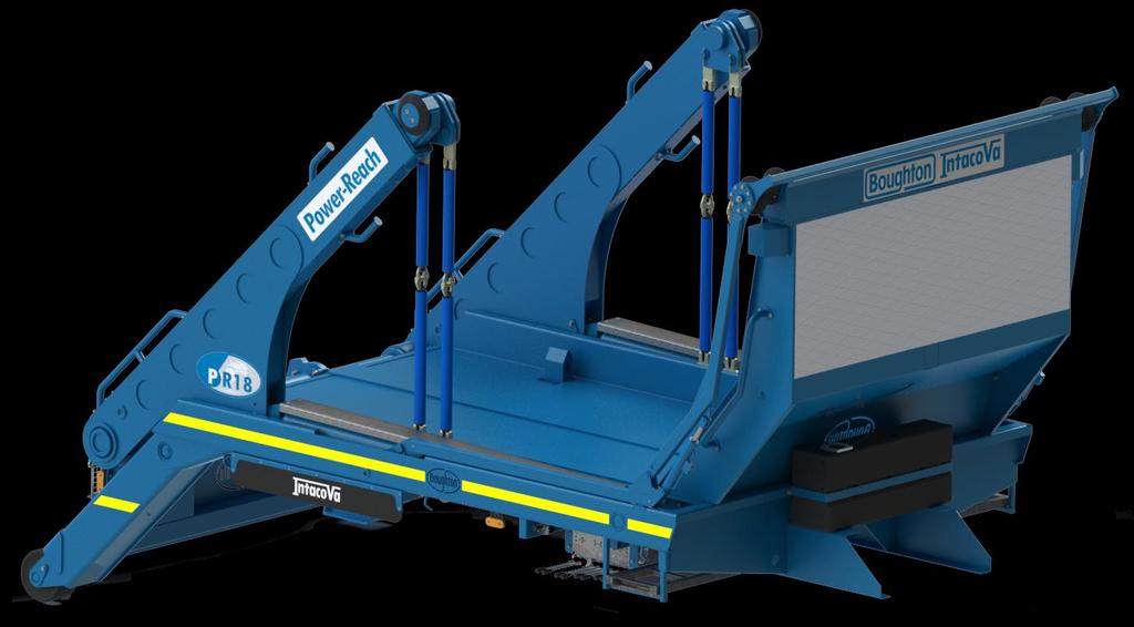
8 2. Skiploader General Arrangement Telescopic Lifting Arm Adjustable Skip Stops - Lateral Cab Guard Main Lifting Arm Lifting Chains Main Lift Arm Hydraulic Cylinder Main Control Valve Block Access Ladder (Both Sides) Hydraulic Fluid Tank Lift Chain Stowage Intacova Sheeting System (Optional) Load Bed Tiphooks Access Cover Stabiliser Option Pad* Stabiliser Option Roller* Adjustable Skip Stops - Front * All skiploaders will have flat feet (Pad) rear stabilisers fitted unless the chassis is fitted with front axle parking brakes, in which case, roller stabilisers can be fitted 5.
9 Q P N M L B 3. Skiploader Weights & Dimension ` Model: Power-Reach PR 18 S A K C D H J R G F A Bed Length 3520 mm B Height from top of chassis 2214 mm C Arm extension 1370 mm D Chassis cut-off to load centre 2149 mm E Overall length 4884 mm F Chassis cut-off to stabiliser (raised) 397 mm G Bed width 1990 mm H Distance between lift arms 2127 mm J Distance between tip hook centres 610 mm K Overall width 2540 mm L Overall height from top of chassis to top of cab guard 1963 mm M Chassis bed height 293 mm N Top of chassis to stabiliser (raised) 683mm P Top of chassis to stabiliser (lowered) 1116mm Q Maximum lift from below ground 2147mm R Load arm angle of rotation 139 S Cab guard overhang 567mm Weight of Skiploader including PTO/Pump and hydraulic oil (excluding sheeting system) 3650kg Safe working load (SWL) - arms in Safe working load (SWL) - arms out 12500kg 7500kg 6.
10 4. Intacova Dimensions The information in this section relates to the Intacova sheeting system. This system is an optional fitment and may not be installed on all vehicles. IntaCova Dimensions A Height from top of chassis 2244mm B Maximum width 2550mm C Main arm maximum radius 3392mm D Secondary arm radius 1572mm To sheet at 1500rpm To unsheet at 1500rpm To sheet at tickover To unsheet at tickover Cycle Times 24 seconds 24 seconds 31 seconds 31 seconds Container Sheeting Range 4yd³ (3.06m³) - 16yd³ (12.23m³) Containers should comply with C.H.E.M. standards 7.

11 5. Main Control Valve Block Overview Push Button (Tip Hooks Control) Levers - A B C D E F G H The skiploader equipment is operated using the hydraulic control block situated on the vehicle offset behind the cab. Lever A Hold to run lever - must be in either the up or down position when operating the equipment. In the up position the equipment can carry out a fast unload sequence provided that any skip lifted is EMPTY. During load or unload sequences, with loaded skips, lever A must be in the down position. Note: All levers operate on the dead man principle and return to the neutral position if released. To activate any of the controls the user must apply pressure to lever A at all times. Levers G and H operate the Intacova sheeting system. These levers will not be present if the Intacova system is not fitted to your vehicle. Standard Control Functions Levers B,C,D,E & F Lever Up Lever Down Lever B Main Arms Lever C Telescopic Arm - LH Lever D Telescopic Arm - RH Lever E Stabiliser LH Lever F Stabiliser RH 8.


12 Note: When extending or retracting the telescopic arms and stabiliser legs operate both levers at the same time to synchronise left and right sides. Fine tune to level off by operating one or other lever. Operate Levers Together To Synchronise. Standard Control Functions Push Button The push button located above and to the left of the control levers raises and lowers the tip hooks. When tipping the tip hooks must be in the raised position. For all other operations the tip hooks must be lowered. Pull To Raise Push To Lower Tip Hooks Optional Control Functions Levers G & H Levers G & H are only present on the control panel if the optional Intacova sheeting system is fitted to the vehicle. Lever Up Lever Down Lever G Sheeter Main Arms 9. Lever H Sheeter Secondary Arms


13 6. Adjustable Skip Stops This vehicle is fitted with sockets towards the front and along the sides of the load platform. Six skip stop blocks are supplied with the vehicle, two for positioning at the front of the platform and two pairs for positioning down the sides. Adjustable Front Skip Stops The skip stops, when fitted, restrain any potential forward or sideways movement of any skip loaded onto the vehicle. Each stop is asymmetrical giving two stop positions for each socket depending on which way around the stop is inserted into the socket. For the front stops there are effectively 8 positions. For the side stops there are effectively 4 positions Adjustable Lateral Skip Stops Skip Stop Width and Length Options Side skip stop positions should be chosen so that the guides are the tightest practical fit to the width of the skip Front stop positions should be chosen to ensure that if a skip shifts forward on the platform no part of the skip can come in contact with the cab guard at the front of the load bed. 10.


14 7. Warning Lights A bank of three LED warning lamps is located on the dashboard of the vehicle cab. The warning lamps are activated by proximity sensors which detect:- 1. Stabiliser feet not in fully raised position. 2. Telescopic arms not in fully retracted position. In Cab LED Warning Lamps 3. Main arms not in fully down position. If any of the LED warning lamps is lit the driver of the vehicle should inspect the skiploader equipment to ascertain the positions of the three items listed above. Note: The minimum travel height is the height of the skiploader equipment with the telescopic arms fully retracted and the main arms in the fully down position. The height quoted on the vehicle height notice, located in the vehicle cab, relates to the equipment when at the minimum travel height. Operating the vehicle outside the overall height limit specified on the vehicle height notice may result in prosecution. WARNING It is the drivers responsibility to always ensure that the vehicle is operated within overall heights specified on the vehicle height notice located in the cab. Failure to ensure that the vehicle height is within this limit may result in a collision which may cause damage to the vehicle and/or other structure. Always ensure that, before driving on the highway, all LED warning lamps are extinguished. The LED warning lamps are fitted with a test button. It is recommended that the driver operates the test button after each load/unload sequence prior to driving off. Press Button To Test LED Operation The button should be pressed and held. The warning lamp bank is operating correctly if all three lights illuminate. 11.
15 8. General Safety Checks Prior To Operating When operating the skiploader equipment it is essential that all precautions are taken to ensure the safety of the driver and the general public. Operators of commercial vehicles will have procedures in place to minimize risks. These procedures should always be followed. In addition the following safety checks are specific to skiploader operations and should be carried out prior to any lifting operations:- 1. A general visual inspect of the skiploader equipment should be undertaken. Walk around the vehicle looking for any signs of damage to components. Look for patches of fluid under the vehicle. If fresh fluid is detected inspect the vehicle in the area above the patch to see if there are any leaks. If damage or leaks are detected take the vehicle for repair by a qualified technician. WARNING NEVER operate the equipment if there is a known fault. Take the vehicle out of service and affect a repair before returning into service. Only qualified technicians should carry out repair of faulty equipment. Continued use of faulty equipment may result in serious injury, death or damage to the equipment. 2. Before loading or unloading a skip check the ground onto which the vehicle must drive to ensure it is stable enough to support the loads imposed through the stabilising legs. The ground should be essentially level. Although the stabilising jacks will level off a limited amount of inconsistency, in ground level, excessive slopes may result in an unstable lift. 3. Ensure that the area around the skip is clear. DO NOT carry out a loading or unloading operation if any person or animal is close to the vehicle or skip. It is recommended that a 1.5 metre clearance zone, around vehicle and skip, is applied. Clearance Zone 12.
16 4. Check the area above the vehicle and lifting equipment. DO NOT lift if there is any risk of a collision. 5. When unloading ensure that there is adequate space to accommodate the skip. To reduce the risk of a crushing hazard it is recommended that there is space all around the skip when unloaded. 6. Check the skip prior to lifting to ensure that it is in sound condition. Take particular note of the condition of the lifting lugs and, if tipping, the tipping bar. If loaded check that the load is safely inside the skip and cannot fall out during the lift. It is the operator s responsibility to ensure that a skip is not overloaded. Check the skip load. If there is any doubt that the skip may be overloaded DO NOT attempt a lift. 7. Check the lifting chains to ensure that they are in sound condition. Make sure that the chains are not knotted or twisted. WARNING Lift chains are critical safety components. DO NOT attempt to modify the lift chains by changing their length. DO NOT attempt repair of chains by cutting or welding. If a chain is damaged or worn beyond usable limits it must be replaced. Serious injury and/or damage to the vehicle may result from using damaged or worn lift chains. 13.
17 9. Operating The Skip Loader Equipment In these instructions the following symbols are used to indicate the correct levers to operate when completing an instruction:- Lever Up Push Button Lever Down Note: Limit the operation of the hydraulic system to 30 minutes at a time where possible. Excessive operation will warm up and thin the hydraulic fluid resulting in reduced performance Loading a Skip Prior to starting operation read through the General Safety Checks Prior To Operating section 8, and assess the skip and its location to ensure that it is suitable for lifting. 1. Reverse skiploader vehicle to a position in front of the skip. Position the rear of the vehicle as close to the skip as possible. 2. Apply hand brake. 3. Engage PTO. 4. Check that the tip hooks are in the down position. If the tip hooks are up, push the tip hook button in to lower. Button: 5. Extend stabiliser legs. The legs should be extended so that the load is just removed from the rear suspension. Note: The stabilisers should be used to level the rear of the vehicle. The rear wheels should remain in contact with the ground to retain the effectiveness of the handbrake. 6. Rotate the main arms. Use the fast unload (move lever A up). Rotate arms until the chain pivot is just above skip top. Levers - A B C D E F G H Push Button Pull Button 14.

18 7. Extend the telescopic arms, if necessary, to place the chain pivot centrally over the skip lifting lugs. 8. Attach the four chain key plates to the lifting lugs. Ensure that the plates are fully over the lug and that the chains are not twisted or tangled. 9. Lift the skip off the ground using the main arms. Note: To ensure that the skip does not collide with the rear of the vehicle use the telescopic arms to increase clearance. Keep the skip as close to the vehicle as possible whilst maintaining clearance. Stop the loading cycle just prior to the skip resting on the load bed and check that the skip stops have been correctly positioned. WARNING Do not attempt to reposition the skip stops with the skip supported on chains over the platform. Remove the skip from over the load bed reposition the guides then reload the skip. Failure to observe this warning will result in a potential crushing hazard which may cause serious injury or death. 10. With correctly positioned skip stops complete the loading sequence by resting the skip on the load bed. Ensure that the main arms are rotated to the fully down position and that the telescopic arm is fully retracted. 11. Retract the stabiliser legs. 15.
19 Prior to driving on the highway a check should be made to ensure that the vehicle and its load are safe. Check LED warning lamps in cab. If any lights are illuminated check:- 1) Main arms. 2) Telescopic arms 3) Stabilisers Ensure that they are in the safe driving position. If no sheeting system is fitted and the vehicle is ready to depart ensure that the PTO is disengaged. If the vehicle is fitted with an Intacova sheeting system deploy the sheeting system prior to driving off, see below Deploying Intacova Sheeting System The Intacova sheeting system (when fitted) must always be deployed when carrying a loaded open top skip to prevent potential loss of load during transit. 1. With the skip in position on the vehicle load bed activate the Intacova main arms bringing the sheeting system over the skip. 2. Operate the main arms until the sheeting roller has rotated beyond the rear of the skip. 3. Activate the Intacova secondary arms. The sheeting roller will move forward, in an arc, pulling the sheet over the rear of the skip. Continue operating the secondary arms until the roller contacts with the main lifting arms. With the sheeting system deployed disengage the PTO prior to departure. 16.


20 9.3. Retracting Intacova Sheeting System Prior to unloading or tipping a skip ensure that, if fitted, the Intacova sheeting system has been retracted. 1. Engage PTO. 2. Rotate secondary arms away from the rear of the skip. 3. Ensure sheeting roller is clear of the rear of the skip before proceeding. 4. Activate the Intacova main arms to bring the sheeting system over the skip towards the load bed cab guard. A continual check must be made to ensure that no collision takes place between the Intacova and any other part of the vehicle structure during this operation. Main Arm Spigot 5. The Intacova sheeting system is fully retracted when the main arm spigot is engaged in the socket on the side rave of the load bed and the sheet roller is sitting down in the cups at the top of the cab guard. Socket It may be necessary to further use the sheeter main arm and secondary arm controls to ensure that the system is fully retracted and in the drive away position. Cup WARNING Ensure that the Intacova sheeting system is fully retracted before driving the vehicle. Failure to fully retract the sheeting system may result in damage caused through collision. 17.
21 9.4. Unloading a Skip Prior to starting operation read through the General Safety Checks Prior To Operating section 8, and assess the proposed unload location to ensure that it is suitable. Take particular note of the available space and stability of the ground and ensure that there is adequate clearance behind the vehicle to accommodate the skip when unloaded. 1. Drive the vehicle into position. 2. Apply handbrake. 3. Engage PTO. 4. Extend stabiliser legs. The legs should be extended so that the load is just removed from the rear suspension. Note: The stabilisers should be used to level the rear of the vehicle. The rear wheels should remain in contact with the ground to retain the effectiveness of the handbrake. 5. Check that the tip hooks are in the down position. If the tip hooks are up, push the tip hook button in to lower. Button: 6. Check that all four chains are securely attached to the skip lifting lugs. 7. Rotate the main arms and lift the skip off the load platform. Note: It may be necessary to extend the telescopic arms, prior to lifting, to avoid the skip dragging back along the platform. Check that the chain pivot is central over the skip just as the chains tighten. Note: If an empty skip is being unloaded the fast unload facility may be used. Lever A and lever B should be in the up positions for fast unload. This function will not operate if an attempt is made to lift a fully loaded skip. 18.


22 Note: When operating in fast unload mode the main arm lever will operate in the unload direction when in the up or down position. Care must be taken if circumstances arise which require the skip to be reloaded onto the vehicle. Lever A and lever B must be moved to the down position to facilitate reloading of the skip. 8. Continue the off load using the main arms. Rotate the skip over the rear of the vehicle and onto the ground. Continue rotating the main arms until there is sufficient slack in the lift chains to allow them to be disconnected from the skip lifting lugs. 9. Detach the chains from the skip lifting lugs and stow on the chain hooks provided on the main lift arms. 10. Rotate main arms until they are in the fully down position. 11. Retract telescopic arms around until they are in the fully down position. 12. Retract the stabilisers. A check should be made to ensure that the vehicle skiploader system is correctly set up prior to driving on the highway. Check LED warning lamps in cab. If any lights are illuminated check:- 1) Main arms. 2) Telescopic arms 3) Stabilisers Ensure that they are in the safe driving position. Disengage the PTO prior to departure. 19.
23 9.5.Tipping a Skip The skiploader system can be used to tip a loaded skip provided the skip is equipped with tipping bars designed for the purpose. Prior to starting operation read through the General Safety Checks Prior To Operating section 8, and assess the skip and the intended tipping location to ensure that they are suitable. Any sheeting must be removed from the skip prior to commencing the tipping procedure. Refer to section 9.3 for instructions on retracting the Intacova sheeting system. 1. Drive the vehicle into position. 2. Apply handbrake. 3. Engage PTO. 4. Extend stabiliser legs. The legs should be extended so that the load is just removed from the rear suspension. Note: The stabilisers should be used to level the rear of the vehicle. The rear wheels should remain in contact with the ground to retain the effectiveness of the handbrake. 5. Check that all four chains are securely attached to the skip lifting lugs. 6. Raise the tip hooks. Button: 7. Rotate the main arms and lift the skip off the load platform. Note: It may be necessary to extend the telescopic arms, prior to lifting, to avoid the skip dragging back along the bed. Check that the chain pivot is central over the skip just as the chains tighten. 20.
24 8. Rotate the main arms around until the tipping bar on the skip contacts the leading edge of the tip hooks. The tipping bar should contact the leading edge approximately 100mm below the throat of the hook. Use the telescopic arms to adjust the height of the skip until the required 100mm is achieved. Correct 100 Incorrect Once the skip tipping bar is correctly located against the leading edges of the tip hook the telescopic arms must not be operated throughout the remainder of the tipping sequence. WARNING If the skip tipping bars are engaged directly into the throat of the tip hooks, or the telescopic arm controls are operated when the skip tip bars are engaged in the throat of the tip hooks, the tip hooks and mountings may be damaged. 9. Rotate the main arms rearward, allowing the tipping bar to engage in the throat of the hook. The skip will start to tip as the main arms rotate. 10. Continue rotating the main arms rearward until the load has cleared the skip. Do not allow the skip to touch the ground or any other obstacle during the tip cycle. WARNING During the tip cycle, in the event that the load does not discharge under no circumstances should anyone attempt to dislodge the load manually with the skip in the tipped condition. Return the skip to the horizontal position and repeat the tip cycle. Do not walk behind the vehicle at any time when tipping. 11. On completion of the tip rotate main arms forward to return the skip to the horizontal position. 21.
25 12. Complete the loading sequence by resting the skip on the load bed. Ensure that the main arms are rotated to the fully down position and that the telescopic arm is fully retracted. 13. Retract the stabilisers. 14. Lower the tip hooks. A check should be made to ensure that the vehicle skiploader system is correctly set up prior to driving on the highway. Check LED warning lamps in cab. If any lights are illuminated check:- 1) Main arms. 2) Telescopic arms 3) Stabilisers Ensure that they are in the safe driving position. Disengage the PTO prior to departure. 22.

26 10. Maintenance SAFETY WARNING Correct maintenance of this equipment is essential for safe operation. Always maintain the equipment to the schedule prescribed. Only trained technicians should be permitted to carry out maintenance and repair work on the skiploader equipment. NEVER operate the equipment if there is a known fault. Take the vehicle out of service and affect a repair before returning into service. DO NOT carry out any modification or adjustment (not described in this manual) to the skiploader equipment without obtaining written consent from Boughton Engineering Ltd. Maintenance work should always be carried out with the vehicle unladen. In the event of emergency repairs, by the roadside, all efforts must be made to remove any load prior to commencing work. When working on the equipment always ensure that it is disabled to prevent accidental operation of moving parts. Remove the vehicle ignition key unless a test on the equipment is to be run. Ensure that the area around and under the vehicle is clear before activating and operating the equipment. Work should be carried out with rams in the closed position wherever possible. ALWAYS ensure that hydraulic systems are unpressurised before disassembly. When working with hydraulic fluids care must be taken to avoid contact with the skin and/or ingestion. Hydraulic fluid can be harmful to the environment. Clean up any spillages immediately and dispose of any waste fluid conscientiously. ALWAYS use approved spares and recommended fluids and lubricants. Non approved items may seriously affect the performance and will increase the risk of a failure. After carrying out maintenance or repair work a check should be made to ensure that all safety devices operate correctly. 23.
27 Schedule Safety, life expectancy and performance of the skiploader equipment is significantly enhanced if maintenance is carried out as prescribed. The vehicle and skiploader equipment should be washed regularly (recommend washing weekly and more frequently if the type of operation demands). A build up of tipped materials on the bed, or around all moveable parts, can cause damage. In particular pay attention to the hydraulic cylinders, pivot points and stabiliser leg within the stabiliser housings. Wipe, with a clean cloth, all exposed piston rods. Daily Checks by the Vehicle Operator (Driver) Check Check Type Action Check for hydraulic leaks. Check hydraulic tank level. Use sight gauge cylinders must be closed. Check Hydraulic fluid filter is not blocked. Check for pneumatic leaks. Check operation of the in cab warning lights. Check condition of lift chains. Check condition of hydraulic hoses. Check condition of all structural parts of lift equipment. Visual Visual Visual Audible Operation Visual Visual Visual Immediately report any leaks for investigation and repair. Immediately report low levels for rectification Maintenance procedure 1. Immediately report a blocked filter for rectification Maintenance procedure 2. Immediately report any leaks for investigation and repair. See section 7 for warning light checks. Report for investigation and repair if warning lights fail test or warning lights do not extinguish. Immediately report any damage or wear. Replace chains before commencing operation Maintenance procedure 3. Immediately report any damage for investigation and repair. Immediately report any damage for repair. Maintenance Schedule Workshop The following schedule and procedures should be carried out by a qualified technician in a workshop environment. RECOMMENDED HYDRAULIC OIL Fuchs Renolin CL32 Hydraulic Oil 'A' Mobil D T E 25 Shell Tellus 46 Castrol Hyspin AWS 46 RECOMMENDED GREASE Fuchs (Century Oils) Renolit MP3 Mobilgrease MP Shell Alvania R3 Castrol Spheerol AP3 24.


28 6 Weekly 6 Monthly Annually Procedure Daily Checks See Above x x x 1, 2 & 3 Grease all grease points x x x 4 Grease stabiliser leg stanchions x x x 5 Check nut and bolt torque values x x x 6 Replace hydraulic fluid filter *See Note x x 2 Renew hydraulic fluid x 7 *Note Due to initial component bedding in, the hydraulic fluid filter must be changed at the first 6 weekly maintenance check. Thereafter filters should be changes every 6 months. Maintenance Procedure 1 Check and Fill Hydraulic Tank Max Line Min Line The level of fluid in the hydraulic tank can be checked using the site glass situated on the tank offside. Prior to checking the fluid levels ensure that all hydraulic cylinders are in the full closed position. The fluid level must be between the maximum and minimum indicator lines. Hydraulic Tank Site Gauge If the level of fluid is near to or below the min line then the fluid must be topped up. Note: Topping up of the hydraulic should be carried out by a qualified technician in the workshop:- 1) Access the top of the hydraulic tank through the hatch at the base of the platform bulkhead (fig 1.1). 2) Unscrew the tank filler cap (fig 1.2). 3) Top up the tank to the maximum level line using recommended fluid types. 4) Check that the tank filler cap vents are clear before replacing filler cap. Fig 1.1. Access Panel Fig 1.2. Filler Cap Removed 25.

29 Maintenance Procedure 2 Filter Check/Change Filter Housing With Pressure Gauge To check to ensure that the hydraulic fluid filter is not blocked the PTO must first be engaged. View the filter housing, located on the top of the hydraulic fluid tank, from the vehicle offside. The gauge on the side of the housing indicates the line pressure in the return line. The gauge must show a pressure reading in the green zone. If the reading is in the red zone this indicates a blockage and the filter should be removed and replaced Note: Changing the hydraulic fluid filter should be carried out by a qualified technician in the workshop:- 1) Ensure PTO is disengaged. 2) Access the top of the hydraulic tank through the hatch at the base of the platform bulkhead (fig 2.1.). 3) Turn the filter cap anticlockwise to remove and gain access to the filter (fig 2.2). Note: The filter cap is sprung against the filter and will be pushed away from the housing when the threads disengage. 4) Remove the filter from the housing (fig 2.3). 5) Fit a new filter (fig 2.4). 6) Replace filter cap. Note: Push the filter cap down, to compress the filter spring, and turn clockwise to engage the threads (fig 2.5). Fig 2.1 Fig 2.2 Fig 2.3 Fig 2.4 Fig
30 Maintenance Procedure 3 Chain Inspection Lift chains should be carefully inspected to ascertain if they are serviceable. Check that the chain does not exhibit the following characteristics:- 1) Chain stretch the links of the chain elongate causing the overall chain length to increase. 2) Deformation through bending or twisting of the links. 3) Chain wear the links wear at the bearing surfaces weakening the chain and causing the overall chain length to increase. 4) Cracks in the links. New Link Chain Stretch Links Close Up As They Elongate Stretched Link Wear Wear at Bearing Surfaces Bent Bent Twisted Any chain exhibiting any of these characteristics should be replaced and taken out of service. WARNING Lift chains are critical safety components. DO NOT attempt to modify the lift chains by changing their length. DO NOT attempt repair of chains by cutting or welding. If a chain is damaged or worn beyond usable limits it must be replaced. Serious injury and/or damage to the vehicle may result from using damaged or worn lift chains. 27.


 Main")


31 Maintenance Procedure 4 - Grease Points Grease points are located as shown in the diagram below. Use a grease gun to apply grease to the bearing surfaces at these locations. Tiphook Pivot Bearing Chain Mounting Pivot Main Hydraulic Cylinder Pivot Rear Main Hydraulic Cylinder Pivot Front Main Arm Pivot Bearing Stabiliser Rear Stabiliser Front Intacova (Optional) Main Arm Lower Maintenance Procedure 5 Grease Stabiliser Leg Stanchions Apply Grease to All Surfaces Apply grease to the stabiliser leg inner stanchion. Extend the stabiliser leg to expose the inner box surfaces. The grease should be applied liberally to the box section surfaces and spread using a brush. After application retract the stabiliser legs and clean away any excess grease. 28.


32 Maintenance Procedure 6 Check Nut & Bolt Torque Values All nuts and bolts should be checked to ensure that they are at the correct torque. Use a calibrated torque wrench set to the required torque. Recommended tightening torque for the chassis mounting bolts 201Nm. Recommended tightening torque for main arm pivot cap bolts - 312Nm. For all other fasteners use the following table which gives recommended tightening torques for various metric bolts. Quoted U torque values are for self colour un-lubricated bolts and zinc plated bolts into unplated holes and nuts. Quoted P torque values are for zinc plated bolts into zinc plated nuts. For cap screws use grade 10.9 torque values. Nominal Bolt Size Grade 8.8 U Torque Nm Grade 8.8 P Torque Nm Grade 10.9 Torque Nm Course Fine Course Fine Course Fine M M M M M M M M M M M


 Shut off the stop cock on the hydraulic fluid suction line. The stop cock is located underneath the hydraulic fluid tank (see fig 7.1).")
33 Maintenance Procedure 7 Renew Hydraulic Fluid Hydraulic fluid is hydroscopic and over time will absorb water. Contaminated fluid will reduce the performance of the hydraulic system. Frequent changes of the fluid, see schedule, are essential to maintain optimum performance. During the change procedure old fluid must be drained from the hydraulic fluid tank. A suitable container, with a capacity of approximately 100 litres, will be required to drain the fluid into. The container will be positioned underneath the vehicle and must be shallow enough to fit in the space available. Note: The following hydraulic fluid change procedure must be carried out with all hydraulic cylinders in the closed position. 1) Ensure PTO is disengaged. 2) Shut off the stop cock on the hydraulic fluid suction line. The stop cock is located underneath the hydraulic fluid tank (see fig 7.1). 3) Disconnect the suction line at the hydraulic pump, located on the back of the PTO (see fig 7.2). 4) Position the detached end of the suction line in the container into which the old fluid will be drained. 5) Remove the hydraulic tank filler cap (see fig 7.3). 6) Open the stop cock on the hydraulic fluid suction line. The hydraulic fluid will drain from the tank into the container. 7) When the hydraulic fluid tank is empty shut off the suction line stop cock. 8) Re-connect the suction line to the hydraulic pump. 9) Fill the tank with new hydraulic fluid to the recommended specification. The tank should be filled to the maximum line on the tank sight gauge (see fig 7.4). 10) Re-place the tank filler cap. Max Line Fig 7.1 Suction Tube Stop Cock Fig 7.2 Suction Tube Fig 7.3 Filler Cap Fig 7.4 Hydraulic Tank Site Gauge After completing the fluid change clean up any spilt hydraulic fluid. Old fluid must be disposed of responsibly. 30.
34 11. EC Declaration of Conformity We: Of: Boughton Engineering Limited Balliol Business Park, Wobaston Road, Wolverhampton. WV5 9EU. United Kingdom Hereby declare that: Equipment: Power Reach Skiploader System & Power Reach Skiploader with Intacova Sheeting System Model number: PR 18 & PR 18 + Intacova Serial Number : complies with all applicable essential requirements of the Machinery Directive 2006/24/EC. Signed: Name: Carl Holroyd Position: Engineering Director Location: Wolverhampton, United Kingdom. Date: 2 September 2013 The technical file for the machinery covered by this directive is available from: Name: Carl Holroyd Address: Balliol Business Park, Wobaston Road, Wolverhampton. WV5 9EU. United Kingdom Document No: BEL-PR18-DC 31.
 1902 623430 Fax: +44 (0) 1902 787265 Email: enquiries@boughtonengineering.")
35 12. Further Information For further information or assistance in operating the PR18 Skiploader and Intacova Sheeting System contact:- Boughton Engineering Ltd, Balliol Business Park, Wobaston Road, Wolverhampton. WV5 9EU. Tel: +44 (0) Fax: +44 (0)
OPERATING MANUAL C-1350 CABLE PUSHER. Copyright 2003 by CBS Products (KT), Ltd
, Ltd") CBS Products (KT), Ltd, Pillings Road, Oakham, Rutland, LE15 6QF. UK Telephone: +44(0)1572723665 Fax: +44(0)1572 756006 E-Mail: sales@cbsproducts.com Website:www.cbsproducts.com OPERATING MANUAL C-1350
CBS Products (KT), Ltd, Pillings Road, Oakham, Rutland, LE15 6QF. UK Telephone: +44(0)1572723665 Fax: +44(0)1572 756006 E-Mail: sales@cbsproducts.com Website:www.cbsproducts.com OPERATING MANUAL C-1350
Operators manual Bumpa 8 metre 110v Bumpa 10 metre 110v
 Operators manual Bumpa 8 metre 110v Bumpa 10 metre 110v SAFETY RULES Mk3 Bumpa Conveyor Danger Failure to obey the instructions and safety rules in this manual will result in death or serious injury. Do
Operators manual Hoddi 6 metre 110v Bumpa 8 metre 110v Bumpa 10 metre 110v
 Operators manual Hoddi 6 metre 110v Bumpa 8 metre 110v Bumpa 10 metre 110v SAFETY RULES Mk3 Bumpa Conveyor Danger Failure to obey the instructions and safety rules in this manual will result in death or
HEAVY DUTY TROLLEY JACK. Operation Manual
 HEAVY DUTY TROLLEY JACK 4T Operation Manual Make sure to read and fully understand the instruction manual before using this product and keep the manual properly 1 General Description Product Description
3.25 Ton Heavy Duty Floor Jack
 Please dispose of packaging for the product in a responsible manner. It is suitable for recycling. Help to protect the environment, take the packaging to the local amenity tip and place into the appropriate
3 Ton Trolley Jack. Please read and fully understand the instructions in this manual before operation. Keep this manual safe for future reference.
 Please dispose of packaging for the product in a responsible manner. It is suitable for recycling. Help to protect the environment, take the packaging to the local amenity tip and place into the appropriate
Operating Manual. Pantographs. Version 05/12.
 Operating Manual Pantographs Version 05/12 Parts & Features A pantograph is a mechanical device that enables a load to be suspended by the means of balancing the load with two or more constant tension
5 CAR TRUCK SUPERSTRUCTURE DRIVERS INSTRUCTION MANUAL
 5 CAR TRUCK SUPERSTRUCTURE DRIVERS INSTRUCTION MANUAL Britain s premier Car Transporter manufacturer FOR THE ULTIMATE IN QUALITY AND SERVICE PLEASE CONTACT US AT The Old Airfield, Gosfield, Halstead, Essex
DIGITAL BATTERY TORQUE WRENCH (BC-RAD SELECT) USER GUIDE
 USER GUIDE") DIGITAL BATTERY TORQUE WRENCH (BC-RAD SELECT) USER GUIDE W.CHRISTIE (INDUSTRIAL) LTD CHRISTIE HOUSE, MEADOWBANK ROAD, ROTHERHAM, SOUTH YORKSHIRE, S61 2NF, UK T: +44(0)1709 550088 F: +44(0)1709 550030 E:
DIGITAL BATTERY TORQUE WRENCH (BC-RAD SELECT) USER GUIDE W.CHRISTIE (INDUSTRIAL) LTD CHRISTIE HOUSE, MEADOWBANK ROAD, ROTHERHAM, SOUTH YORKSHIRE, S61 2NF, UK T: +44(0)1709 550088 F: +44(0)1709 550030 E:
50 TONNE HYDRAULIC PRESS MODEL NO: CSA50FP
 50 TONNE HYDRAULIC PRESS MODEL NO: CSA50FP PART NO: 7615202 OPERATION & MAINTENANCE INSTRUCTIONS WARNING: Read these instructions before using the press GC0516 INTRODUCTION Thank you for purchasing this
VEHICLE POSITIONING JACK
 VEHICLE POSITIONING JACK Model No: VPJ300 PART NO: 7624100 OPERATING & MAINTENANCE INSTRUCTIONS GC06/12 INTRODUCTION Thank you for purchasing this CLARKE Vehicle Positioning Jack. Before attempting to
20 TONNE HYDRAULIC PRESS MODEL NO: CSA20FBT
 20 TONNE HYDRAULIC PRESS MODEL NO: CSA20FBT PART NO: 7614058 OPERATION & MAINTENANCE INSTRUCTIONS WARNING: Read these instructions before using the press GC0516 INTRODUCTION Thank you for purchasing this
CPCS renewal test factsheet
 CPCS renewal test factsheet Introduction to the CPCS renewal test The industry-led CPCS Management Committee has determined that key safety-related knowledge must be checked on each category prior to the
ABSOLUTE EQUIPMENT PTY LTD
 Manual Hydraulic Toe Jack Model DTJ Series ABSOLUTE EQUIPMENT PTY LTD 2/186 Granite Street, GEEBUNG QLD 4034 Australia sales@absoluteequipment.com.au Phone: +61 7 3865 4006 Fax: +61 7 3102 6288 This is
2 TONNE GARAGE JACK Model No: CTJ2QLP PART NO:
 TONNE GARAGE JACK Model No: CTJQLP PART NO: 7680 OPERATING & MAINTENANCE INSTRUCTIONS GC03 INTRODUCTION Thank you for purchasing this CLARKE Garage Jack. Before attempting to use this product, please read
HYDRAULIC PALLET TRUCK. MODEL No: PTE550 PART Nos OPERATION & MAINTENANCE INSTRUCTIONS
 HYDRAULIC PALLET TRUCK MODEL No: PTE550 PART Nos 7630171 OPERATION & MAINTENANCE INSTRUCTIONS 0604 Please read these instructions carefully before operating the truck Thank you for purchasing this CLARKE
ABSOLUTE EQUIPMENT PTY LTD
 Manual Hydraulic Toe Jack Model DTJ Series ABSOLUTE EQUIPMENT PTY LTD 2/186 Granite Street, GEEBUNG QLD 4034 Australia sales@absoluteequipment.com.au Phone: +61 7 3865 4006 Fax: +61 7 3102 6288 This is
LOG CHOP. Hydraulic Wood Guillotine. Owners Illustrated Instruction Book & Parts List
 LOG CHOP Hydraulic Wood Guillotine Owners Illustrated Instruction Book & Parts List Grovebury Road, Leighton Buzzard, Bedfordshire. LU7 4UX. UK. Tel:01525 375157. Fax:01525 385222. Email: enquires@brownsagricultural.co.uk
Contents (Page 1 of 3)
") EVO8 Drivers Manual Contents (Page 1 of 3) 5 & 6. General Safety 7. Cars by numbers 8. General Vehicle Layout 9. Deck Maximum Load 10. General Data 11. Tyres Pressures 12. Jacking points for trailer Trailer
EVO8 Drivers Manual Contents (Page 1 of 3) 5 & 6. General Safety 7. Cars by numbers 8. General Vehicle Layout 9. Deck Maximum Load 10. General Data 11. Tyres Pressures 12. Jacking points for trailer Trailer
PLATFORM WHEEL WELL ACCESS STAND
 PLATFORM WHEEL WELL ACCESS STAND Page 1 Standards WARNING Safety First Tested in general accordance with the applicable requirements of DIN EN 131 2 : 2012 BS EN 131 7 : 2013 ANSI ASC A14.7 20 2011 The
Instruction Manual For Auto Shift Hydraulic Lift Table
 Instruction Manual For Auto Shift Hydraulic Lift Table Model Number: CART-550-AS Note: Owner/Operator must read and understand this Instruction Manual before operating the lift & tilt table. Contents 1
ODYSSEY Drivers Manual. 1
 ODYSSEY Drivers Manual 1 Contents (Page 1 of 3) 5 & 6. General Safety 7. Cars by numbers 8. General Vehicle Layout 9. Deck Maximum Loads 10. General Data 11. Tyres Pressures 12. Jacking points for trailer
N G 3 S p r i n g B r a k e s
 C o m m e r c i a l V e h i c l e S y s t e m s P r o d u c t M a n u a l N G 3 S p r i n g B r a k e s R ationalised Units for S-Cam Applications P r o d u c t M a n u a l Disclaimer The information contained
2¼ TONNE TROLLEY JACK
 2¼ TONNE TROLLEY JACK Model No: CTJ2250LP PART NO: 7623070 OPERATING & MAINTENANCE INSTRUCTIONS GC01/12 INTRODUCTION Thank you for purchasing this CLARKE Trolley Jack. Before attempting to use this product,
shortform operating instructions
 B 0800 52 15 95 www.facelift.co.uk ascendant 17m shortform operating instructions SAFETY TIPS ALWAYS Inspect your machine before use. Check all operations including ground controls. Check ground conditions.
Model Number: CM-046. QUATTRO Handset Installation guide and user information. Ref: CM-046 UK-Rev.C.
 Model Number: CM-046 QUATTRO Handset Installation guide and user information UK Ref: CM-046 UK-Rev.C. Table of Contents Package Contents (Parts List) Page 2 Introduction Page 4 Installation Safety Guidelines
HYDRAULIC PALLET TRUCKS
 HYDRAULIC PALLET TRUCKS HYDRAULIC PALLET TRUCKS MODEL Nos: PT550 GAL & PT685 GAL PART Nos: 7630234 & 7630236 OPERATION & MAINTENANCE INSTRUCTIONS 0204 Please read these instructions carefully before operating
2 TONNE TROLLEY JACK
 2 TONNE TROLLEY JACK Model No: CTJ2000LP PART NO: 7623065 OPERATING & MAINTENANCE INSTRUCTIONS GC01/12 INTRODUCTION Thank you for purchasing this CLARKE Trolley Jack. Before attempting to use this product,
IMPORTANT INSTRUCTIONS FOR OPERATION & MAINTENANCE OF
 IMPORTANT INSTRUCTIONS FOR OPERATION & MAINTENANCE OF CONVEYORS EASIKIT 300 EASIKIT 450 EASIKIT 600, 900, 1200 & 1500 The manufacturer does not accept responsibility for any loss, damage to other equipment,
English. Fitting Instructions: Trophy and Trophy SE A and A of 10 A Parts Supplied:
 English Fitting Instructions: Trophy and Trophy SE A95086and A950856 Thank you for choosing this Triumph genuine accessory kit. This accessory kit is the product of Triumph's use of proven engineering,
Grease Stand MODEL# DF MAINTENANCE AND OPERATION MANUAL. Page 1
 Grease Stand Page 1 WARNING Safety First Standards Tested in general accordance with the applicable requirements of DIN EN 131 2 : 2012 BS EN 131 7 : 2013 ANSI ASC A147 20 2011 The best insurance against
INTRODUCTION Please read this manual before you use your jack and ensure you understand its operation and the safety procedures to be observed.
 Rated Capacity: 4000kg Closed Height: 19.5cm (approx) Hydraulic Lift: 11.8cm (approx) Maximum Extended Height: 6cm (approx) 4 Tonne Bottle Jack Instruction Manual Item Code: 332343 Model T90404 INTRODUCTION
Finishing Mower Estate 72
 Finishing Mower Estate 72 Owners/Operators Manual & Spare Parts List Issue Date: October 2011 1 Introduction Your FIELDMASTER Estate 72 Finishing Mower has been designed to do a range of work to your satisfaction.
Wind and Temperature Tip Over Hazard Do not add notice boards or similar
 Lift & Work Platform Safety Information Safety Information: Boom Lifts Safety Information: Scissor Lifts Safety Information: Boom Lifts Power Lines Electrocution Hazard Maintain safe clearance from Electrical
OPERATION & MAINTENANCE INSTRUCTIONS
 10 TONNE HEAVY DUTY LONG CHASSIS TROLLEY JACK MODEL NO: CTJ10GLS PART NO: 7623095 OPERATION & MAINTENANCE INSTRUCTIONS LS0915 INTRODUCTION Thank you for purchasing this CLARKE 10 Tonne Heavy Duty Long
HYDRAULIC PALLET TRUCK MODEL NO: PT540M/BM/CM & PT685BM/CM PART NO: , , , ,
 HYDRAULIC PALLET TRUCK MODEL NO: PT540M/BM/CM & PT685BM/CM PART NO: 7631700, 7631705, 7631710, 7631715, 7631720 OPERATION & MAINTENANCE INSTRUCTIONS LS0316 INTRODUCTION Thank you for purchasing this CLARKE
AQUATEC R / AQUATEC F / AQUATEC XL. Bathlift Operating instructions
 AQUATEC R / AQUATEC F / AQUATEC XL Bathlift Operating instructions 1 2 3 4 5 6 7 8 9 10 11 Contents 1 General instructions................. 3 1.1 Introduction......................... 3 1.2 Proper use.........................
CPCS renewal test factsheet
 CPCS renewal test factsheet Introduction to the CPCS renewal test The industry-led CPCS Management Committee has determined that key safety-related knowledge must be checked on each category prior to the
TANKERS OPERATING & SAFETY INSTRUCTIONS FOR SPARE PARTS GO TO
 TANKERS OPERATING & SAFETY INSTRUCTIONS FOR SPARE PARTS GO TO WWW.MARSHALL-TRAILERS.CO.UK FOR MODELS: ST1200, ST1400, ST1600, ST1800, ST2000, ST2300, ST2550 CHARLES J. MARSHALL (ABERDEEN) LTD CHAPEL WORKS,
SD Bendix Manual Slack Adjusters DESCRIPTION ADJUSTING MECHANISM OPERATION
 SD-05-1200 Bendix Manual Slack Adjusters WORM SHAFT (LOCK SCREW) FIGURE 1 - POSITIVE LOCK TYPE SLACK ADJUSTER DESCRIPTION In an s-cam type foundation brake, the final link between the pneumatic system
INSTALLATION OF RAILGEAR KIT R-290HD REAR
 INSTALLATION OF RAILGEAR KIT R-290HD REAR Page 1 of 29 SAFETY PRECAUTIONS If any installation problems are encountered, please call G&B Specialties, Inc. for technical assistance before continuing with
Crane Forks. Introduction. Important Notes. Key Benefits. User Guide
 User Guide Crane Forks Introduction Fully self levelling, even when unloaded, Conquip Crane Forks have been designed to lift packs of bricks and pallets. The crane attachment has adjustable forks and a
Tri-Wheel Wheeled Walker
 Tri-Wheel Wheeled Walker Handle with lever brake Brake cable Handle height adjustment knob Removable basket and tray Large vinyl bag 8 inch (203 mm) wheels user guide Prior to use please read all instructions.
HEAVY DUTY PNEUMATIC TORQUE WRENCH (C-RAD) USER GUIDE
 USER GUIDE") HEAVY DUTY PNEUMATIC TORQUE WRENCH (C-RAD) USER GUIDE Ref: WCOI.041 Date: June 2015 Issue: 4 Page Description CONTENTS 1 Introduction Training Requirements 2 General Safety 3 C-RAD Wrench Models Covered
HEAVY DUTY PNEUMATIC TORQUE WRENCH (C-RAD) USER GUIDE Ref: WCOI.041 Date: June 2015 Issue: 4 Page Description CONTENTS 1 Introduction Training Requirements 2 General Safety 3 C-RAD Wrench Models Covered
1100W PORTABLE GENERATOR
 1100W PORTABLE GENERATOR MODEL NO: G1200 PART NO: 8010110 OPERATION & MAINTENANCE INSTRUCTIONS LS0312 INTRODUCTION Thank you for purchasing this CLARKE 1100W Portable Generator. Before attempting to use
STRUT SPRING COMPRESSOR
 OWNER S MANUAL PRODUCT CODE: 1221T STRUT SPRING COMPRESSOR Capacity Stroke Spring Coil Spring Spring Coil Net Weight (Maximum) Thickness Length Diameter 1,000kg 330mm 10-18mm 210-570mm 100-158mm 36kg Made
Property of American Airlines
 Section 2: Operation 1. GENERAL INFORMATION Safety First! is the motto at Tesco; therefore, the first part of the Operation section begins with safety features and procedures. Operation of the Tesco CL80-20
500kg HYDRAULIC TABLE LIFT
 Product Code: 6007T OWNER S MANUAL PRODUCT CODE: 6007T 500kg HYDRAULIC TABLE LIFT Working Load Limit 500kg Maximum Height 1575mm Minimum Height 440mm Table Dimensions 1010x520mm Wheel Diameter 150mm Made
Automotive Lifting Equipment
 Automotive Lifting Equipment Vehicle Hoists A vehicle hoist / lift is a necessary tool in any automotive repair shop. There are several common types of auto hoists used in repair shops: above ground two
Towing TOWING A TRAILER. Trailer socket
 Towing TOWING A TRAILER E90953 WARNINGS Never exceed the maximum weights for either the vehicle or trailer. Doing so can cause accelerated wear and damage to the vehicle. It can also adversely affect vehicle
Hydraulic Wheel Dolly
 Hydraulic Wheel Dolly Operating Instructions & Parts Manual Model Number HW93766 Capacity 3/4 Ton Made in the U.S.A. This is the safety alert symbol. It is used to alert you to potential personal injury
RINK Model 1622 Series number:
 OPERATION MANUAL AND LIST OF PARTS RINK Model 1622 Series number: WARNING: IN ORDER TO ENSURE SAFE USE OF THE MACHINE AND OPTIMAL RESULTS, IT IS ESSENTIAL TO READ THIS OPERATION MANUAL CAREFULLY BEFORE
Pressure relief valve
 Pressure relief valve Operating manual Series DHV 712 Version BA-2015.10.20 EN Print-No. 300 510 TR MA DE Rev001 ASV Stübbe GmbH & Co. KG Hollwieser Straße 5 32602 Vlotho Germany Phone: +49 (0) 5733-799-0
2 Ton - 50 Ton Bottle Jack
 Please dispose of packaging for the product in a responsible manner. It is suitable for recycling. Help to protect the environment, take the packaging to the local amenity tip and place into the appropriate
Property of American Airlines
 Date Maintenance Check list The inspection and preventive maintenance schedule of the Power Stow Rollertrack is as follows: Daily (10 hrs), Weekly (50 hrs.), every 6 months ( hrs.), yearly (1 hrs.) and
O P E R A T I N G M A N U A L
 O P E R A T I N G M A N U A L - Original - A 5615-2 / Rolltrailer 60 100t Page 1 / 18 Product Seacom Rolltrailer RT 60 100t Serial no. A 5615-2 / 1-35 Customer Grimaldi - Italy Supplier Transport Systems
English. Fitting Instructions: Tiger 800 A of 7. Parts Supplied:
 English Fitting Instructions: Tiger 800 A9708 Thank you for choosing this Triumph genuine accessory kit. This accessory kit is the product of Triumph's use of proven engineering, exhaustive testing, and
English. Fitting Instructions: Tiger 800 A of 7. Parts Supplied:
 English Fitting Instructions: Tiger 800 A9708 Thank you for choosing this Triumph genuine accessory kit. This accessory kit is the product of Triumph's use of proven engineering, exhaustive testing, and
LDG6000SA DIESEL GENERATOR OWNERS MANUAL
 LDG6000SA DIESEL GENERATOR OWNERS MANUAL BEFORE OPERATING THIS EQUIPMENT PLEASE READ THESE INSTRUCTIONS CAREFULLY Preface Thank-you for purchasing this generator. This operation manual contains information
Operation of Fork Lift Trucks
 Operation of Fork Lift Trucks 1. PURPOSE The purpose of this Procedure is to define the rules for the safe operation of Forklift trucks within the University. 2. SCOPE These rules apply to all rider-type
Crane Forks. Introduction. Important Notes. Key Benefits. User Guide
 User Guide Crane Forks Introduction Fully self levelling, even when unloaded, Conquip Crane Forks have been designed to lift packs of bricks and pallets. The crane attachment has adjustable forks and a
HYDRAULIC BENCH PRESS 50,000kg
 OWNER S MANUAL PRODUCT CODE: 2037T HYDRAULIC BENCH PRESS 50,000kg Working Capacity Height Width Depth Weight 50,000kg 1660mm 1220mm 800mm 236kg Made in China to TQB Brands Pty Ltd specifications WARNING
CONTENTS: 5740AH - 40 Ton Air/Hydraulic Shop Press 5750AH - 50 Ton Air/Hydraulic Shop Press OWNER'S MANUAL
 OWNER'S MANUAL CONTENTS: Page 1 Specifications 2 Safety Information and Warranty Information 3 Parts List 4-6 Assembly Instructions 7 Pump and Ram Assembly Instructions 8 Procedure for Bleeding Air 9 Pump
English. Fitting Instructions: Sprint GT 1050 A and A of 12
 English Fitting Instructions: Sprint GT 050 A950855 and A950856 Thank you for choosing this Triumph genuine accessory kit. This accessory kit is the product of Triumph's use of proven engineering, exhaustive
PLATE CLAMPS INSTRUCTION MANUAL
 PLATE CLAMPS INSTRUCTION MANUAL Imported exclusively by Pacific Hoists Pty. Ltd. & Pacific Hoists Ltd. In support of cancer charities in Australia & New Zealand Universal Plate Clamp 1 Horizontal Plate
RUFNEX Series Low Profile Wrenches Operation and Maintenance Manual
 RUFNEX Series Low Profile Wrenches Operation and Maintenance Manual http://www.torsionx.com Use the RUFNEX Series Ultra-Low Profile Wrenches to install and remove large bolts that have minimal wrench clearance.
Multi Bale Handler. No Instruction Manual & Operating Guide
 Multi Bale Handler No. 1412 Instruction Manual & Operating Guide EC Declaration of Conformity in accordance with BS EN ISO/IEC 17050-1:2004 David Ritchie (Implements) Ltd., Carseview Road, Forfar, Scotland
Fitting Instructions: Street Triple Belly Pan Kit - A Warning. 1 of 5. Parts Supplied:
 Fitting Instructions: Street Triple Belly Pan Kit - A9708099 Thank you for choosing this Triumph genuine accessory kit. This accessory kit is the product of Triumph's use of proven engineering, exhaustive
OPERATING AND MAINTENANCE INSTRUCTIONS HYDRAULIC ELECTRICAL PUMPS HAM (Manual control) HAE (Electrical control)
 HAE (Electrical control)") OPERATING AND MAINTENANCE INSTRUCTIONS HYDRAULIC ELECTRICAL PUMPS HAM (Manual control) HAE (Electrical control) Part Nr : HA M 4 6 2 1 B C 1. Essential safety requirements. 2. Technical Characteristics.
OPERATING AND MAINTENANCE INSTRUCTIONS HYDRAULIC ELECTRICAL PUMPS HAM (Manual control) HAE (Electrical control) Part Nr : HA M 4 6 2 1 B C 1. Essential safety requirements. 2. Technical Characteristics.
Maintenance and Operation Manual for Landing Gear Access Stand
 Maintenance and Operation Manual for Landing Gear Access Stand DF071592 03 Liftsafe Fall Protection Inc. Landing Gear Access Stand Manual Page 1 Table of Contents Section Page Number 1.0 Standards 3 2.0
Stone Burier Attachment. BCS Power Units
 Stone Burier Attachment Manufactured by R2 RINALDI S.r.l. to fit BCS Power Units Operating Instructions Before commissioning the machine, read operating instructions and observe warning and safety instructions.
Operating and Maintenance Manual. for. HADEF overhead crane. as jointed crane TA
 5.52.714.00.1.0 Edition 03.2004 GB Operating and Maintenance Manual for HADEF overhead crane as jointed crane TA Subject to changes. 1 HADEF Table of Contents 1 General Page 3 2 Product description Page
PETROL GENERATOR SPG2200, SPG3000, SPG6500 OWNER S MANUAL FOR YOUR SAFETY PLEASE READ THESE INSTRUCTIONS CAREFULLY AND RETAIN THEM FOR FUTURE USE.
 PETROL GENERATOR OWNER S MANUAL SPG2200, SPG3000, SPG6500 FOR YOUR SAFETY PLEASE READ THESE INSTRUCTIONS CAREFULLY AND RETAIN THEM FOR FUTURE USE. WARRANTY This generator is covered by a 24 month warranty
Trolley jack K K K K K K 21242
 Trolley jack K 21240 K 21241 K 21242 K 21241 K 21240 K 21242 1 INSTRUCTIONS FOR USE IMPORTANT Read these instructions carefully and store this manual in a place where you can easily find it as you may
Engine Crane Owner s Manual
 Engine Crane Owner s Manual Model Number ATD04 Capacity Ton WARNING: This product may contain chemicals, including lead, known to the State of California to cause cancer, birth defects or other reproductive
OPERATING AND MAINTENANCE MANUAL
 CBS Products Ltd, Pillings Road, Oakham, Rutland, LE15 6QF. UK Telephone: +44(0)1572 723665 Fax: +44(0)1572 756006 E-Mail: sales@cbsproducts.com Website: www.cbsproducts.com OPERATING AND MAINTENANCE MANUAL
Trench Filler for Compact Utility Loaders
 Form No. 3353-608 Rev A Trench Filler for Compact Utility Loaders Model No. 22472 260000001 and Up Operator s Manual Register your product at www.toro.com Original Instructions (EN) Contents Page Introduction................................
HYDRAULIC MOTORCYCLE LIFT
 HYDRAULIC MOTORCYCLE LIFT MODEL NO: CML5 PART NO: 7610193 OPERATION & MAINTENANCE INSTRUCTIONS LS0713 INTRODUCTION Thank you for purchasing this CLARKE hydraulic motorcycle lift. Before attempting to operate
ASSEMBLY INSTRUCTIONS L-LINE KTG ZMA0304GB
 ASSEMBLY INSTRUCTIONS L-LINE KTG ZMA0304GB 2012-12-01 Delivery information Goods inspection Check that the number of packages agrees with the delivery note and that the packing and goods are not damaged.
HYDRAULIC QUICK HITCH
 HYDRAULIC QUICK HITCH Installation & Operation Manual Important: This manual must be kept with the excavator at all times and referred to as required Harford Attachments Ltd Table of Contents Introduction
3KVA DUAL VOLTAGE GENERATOR MODEL NO: PG3800DV
 3KVA DUAL VOLTAGE GENERATOR MODEL NO: PG3800DV PART NO: 8857815 OPERATION & MAINTENANCE INSTRUCTIONS LS1016 INTRODUCTION Thank you for purchasing this CLARKE 3KVA Dual Voltage Generator. Before attempting
To increase the height of the trailer increase the length, to reduce the height, decrease the length of the link.
 RIDE HEIGHT (CONTINUED) 8.8.2. Trailer Suspension The trailer suspension is set at the factory and should always return to this setting when the height control valve is returned to the central position,
1.5 TON ALUMINUM RACING JACK
 1.5 TON ALUMINUM RACING JACK OWNER S MANUAL WARNING: Read carefully and understand all ASSEMBLY AND OPERATION INSTRUCTIONS before operating. Failure to follow the safety rules and other basic safety precautions
Low Profile Wrenches Operation and Maintenance Manual
 Low Profile Wrenches Operation and Maintenance Manual http://www.torquetoolsinc.com Use the HEXPRO Series Low Profile Wrenches Model 2HP 4HP 8HP 14HP 30HP to install and remove large bolts that have minimal
Power Harrow Attachment. BCS Power Units
 Power Harrow ttachment Manufactured by R2 RINLDI S.r.l. to fit BCS Power Units Operating Instructions Before commissioning the machine, read operating instructions and observe warning and safety instructions.
CPCS renewal test factsheet
 CPCS renewal test factsheet Introduction to the CPCS renewal test The industry-led CPCS Management Committee has determined that key safety-related knowledge must be checked on each category prior to the
GARAGE JACK MODEL NO: CTJ3000G PART NO: OPERATION & MAINTENANCE INSTRUCTIONS ORIGINAL INSTRUCTIONS
 GARAGE JACK MODEL NO: CTJ3000G PART NO: 7623030 OPERATION & MAINTENANCE INSTRUCTIONS ORIGINAL INSTRUCTIONS GC1217 INTRODUCTION Thank you for purchasing this CLARKE Garage Jack. Before attempting to use
ATLAS 2000 SINGLE LINE HYDRAULIC HOIST
 ATLAS 2000 SINGLE LINE HYDRAULIC HOIST OPERATORS INSTRUCTION MANUAL Keep this Manual with the Atlas 2000 Hoist at all times. This will allow new users to read it before operating the Hoist. It is the Atlas
Tailgates By THIEMAN WT20, 30 & 40 PLEASE READ AND UNDERSTAND THE CONTENTS OF THIS MANUAL BEFORE OPERATING THE EQUIPMENT. HIEMAN
 WEIGHTLIFTER Tailgates By THIEMAN WT20, 30 & 40 OWNERS MANUAL/PARTS LIST! IMPORTANT! KEEP IN VEHICLE! PLEASE READ AND UNDERSTAND THE CONTENTS OF THIS MANUAL BEFORE OPERATING THE EQUIPMENT. NATIONAL TRUCK
HYDRAULIC PALLET TRUCK
 HYDRAULIC PALLET TRUCK Models; PT550C & PT685C Part Nos 7630172 & 7630177 OPERATING & MAINTENANCE INSTRUCTIONS GC05/12 INTRODUCTION Thank you for purchasing this CLARKE Pallet Truck. Before attempting
OMEGA. Separator Units. Standen Engineering Limited. Hereward Works, Station Road, Ely, Cambridgeshire. CB7 4BP England.
 OMEGA Separator Units Standen Engineering Limited. Hereward Works, Station Road, Ely, Cambridgeshire. CB7 4BP England. Tel: 01353 661111 www.standen.co.uk Fax: 01353 662370 IMPORTANT This operator s handbook
Installation, operation and maintenance manual
 Installation, operation and maintenance manual HCT1LX30 FULL RISE SCISSOR LIFT READ THIS ENTIRE MANUAL BEFORE INSTALLATION TO ENSURE CORRECT OPERATION AND A LONG SERVICE LIFE 2 Tiraines str. Riga, LV 1058
CPCS renewal test factsheet
 CPCS renewal test factsheet Introduction to the CPCS renewal test The industry-led CPCS Management Committee has determined that key safety-related knowledge must be checked on each category prior to the
IBT Series Square Drive Torque Wrenches
 IBT Series Square Drive Torque Wrenches Operation and Maintenance Manual Model.75, 1, 3, 5, 8, 10, 20, 25, 35, 50 http://www.torsionx.com Use the IBT Series Square Drive Torque Wrenches Model.75, 1, 3,
610 BUSHEL MANURE SPREADER
 610 BUSHEL MANURE SPREADER RODA MANUFACTURING 1008 LOCUST ST. HULL, IA. 51239 Art s-way Manufacturing 712-439-2366 Co., Inc. Hwy 9 West - PO Box 288 WWW.RODAMFG.COM Armstrong, IA. 50514 U.S.A 2 INTRODUCTION
SIP Direct Drive Oil-Lube Air Compressors - Operating & Maintenance Instructions
 SIP Direct Drive Oil-Lube Air Compressors - Operating & Maintenance Instructions Please read and fully understand the instructions in this manual before operation. Keep this manual safe for future reference.
INSTRUCTION MANUAL. Pacific Self-locking Beam Trolleys Pacific Adjustable Angle Clamps Pacific Top Girder Clamps
 INSTRUCTION MANUAL Pacific Self-locking Beam Trolleys Pacific Adjustable Angle Clamps Pacific Top Girder Clamps IMPORTANT Please read this instruction manual before using these products. This manual contains
Low Profile Service Jack
 Low Profile Service Jack Operating Instructions & Parts Manual Model Number JSA200LCX Capacity 2 Ton MAC TOOLS INC. 2005 505 N. Cleveland Ave. Suite 200 Westerville, OH 43082 Printed in PRC Save these
Before equipment use, please read this operation manual carefully. Serial Number: Date Purchased:
 Pushed & Geared Trolleys OPERATION MANUAL This operation manual is intended as an instruction manual for trained personnel who are in charge of installation, maintenance, repair etc. Before equipment use,
PETROL GENERATOR PGH2200, PGH3000, PGH6500 OWNER S MANUAL FOR YOUR SAFETY PLEASE READ THESE INSTRUCTIONS CAREFULLY AND RETAIN THEM FOR FUTURE USE.
 PETROL GENERATOR OWNER S MANUAL PGH2200, PGH3000, PGH6500 FOR YOUR SAFETY PLEASE READ THESE INSTRUCTIONS CAREFULLY AND RETAIN THEM FOR FUTURE USE. WARRANTY GENERATOR SAFETY This generator is covered by