aks-dualo Patient hoist Operating manual
|
|
|
- Lambert Byrd
- 6 years ago
- Views:
Transcription


1 Patient hoist Operating manual Date: 2012_12
2 TABLE OF CONTENTS 1 Introduction 3 2 Intended purpose 4 3 General safety instructions 5 4 Scope of delivery 6 5 Product description 7 6 Assembly 11 7 Commissioning 17 8 Operation 18 9 Patient transport Accessories / Combinations Troubleshooting / fault clearance Care / cleaning When not in use Storage Reuse Service life Disposal Warranty Declaration of conformity Maintenance Technical data 40 Page 2
3 1 Introduction Dear customer, Thank you for choosing our patient hoist aks-dualo. With your aks-dualo you have opted for a hoist which combines the two functions of lifting patients and assisting them to stand in one product. It guarantees you mobility, independence and consequently an improved quality of life. Alongside a high degree of safety, it offers care staff support when performing lifting and moving duties. The mature technology and the convenient configuration ensure safe use. The following basic features are what distinguish the aks-dualo: Optional configuration as standard hoist (for lifting) or active hoist (for assisting to stand) Electromotive lifting and/or standaid function Spreadable chassis legs to increase stability 24 V system with a removable battery pack Can be folded up The aks-patient hoist is available in the following versions: aks-dualo aks-mini dualo Where descriptions and handling instructions in this operating manual refer to all aksdualo versions, we only specify the name of the basic model aks-dualo. Where information is given which is specific to particular versions, these versions, e.g., aks-mini dualo are mentioned explicitly. Read and observe this operating manual before every use. The present operating manual provides you with the information which is important for safe use. Keep the operating manual in the vicinity of the aks-patient hoist so that it is available for reference at any time. Include this operating manual in the case of change of ownership of the aks patient hoist. Page 3
4 2 Intended purpose General The patient hoist aks-dualo is an active class I medical device according to the EU Council Directive 93/42/EEC, Appendix IX. It can be employed in all areas of care work and is intended for use by care staff properly instructed in its operation. It is intended for short-term use not involving contact with injured skin and requires the use of a suitable aks-hoist sling. The patient hoist lift aks-dualo may be used for patients weighing up to max. 150 kg. The patient aks-dualo is only suitable for driving short distances within the patient's flat or area of activity on one floor. It must only be used on an even, horizontal floor. The climatic conditions must be an ambient temperature of 0 C to 40 C, humidity of 20% to 80%, air pressure of 700 hpa to 1060 hpa and in the range of normally composed atmospheric air. It is permitted to be used in wet areas. For example, this includes the toilet or the bath. This does not include using the patient hoist under the shower. The aks-dualo is not explosion protected and is not permitted to be used in potentially explosive areas. Clinical pictures such as osteogenesis imperfecta, osteoporosis or spinal column damage, as well as mental disorientation or epileptic seizures can represent contraindications. The aks-dualo is only permitted to be used after careful consideration of the individual patient by the doctor and the care personnel. Standard hoist In the standard hoist version the aks-dualo is solely to be used for lifting and transferring a patient in a suitable aks-sling. This is usually performed with the patient in a seated position, although it may also be performed when the patient is in a lying position if an aks-spreader bar and aks-sling for transport in the lying position are employed. Patients can even be lifted off the floor. Active hoist In the active hoist version the aks-dualo is solely to be used to assist a patient from a seated position to a standing position and then transfer them in a suitable aks-sling. It serves as an aid to the natural movement of standing up and sitting down and can be driven with the patient standing aboard so that they may still go to the toilet independently for example. Additionally, the patient s participation stimulates his residual mobility by strengthening his circulation and musculature. The use of the active hoist requires the active participation of the patient. The ability to hold on to the lifting arm tightly is particularly important. Missing limbs or functional limitations of the musculoskeletal system (e.g., paraplegia) can limit or rule out the use of an active hoist. This must be decided by the operator on a case-by-case basis. Page 4
5 3 General safety instructions Read the operating manual completely before commissioning in order to avoid damage due to incorrect operation or hazards. It contains important information and instructions which are necessary for the proper operation of the aks patient hoist. The Medical Devices Operator Regulations are binding for the operator / user of medical devices. Only use the aks-patient hoist in accordance with the present operating manual. Keep the operating manual safe for possible reference. Ensure the proper, fault-free condition of the aks-patient hoist and its accessories before every use. Adjustments, exchanging the lifting arm and patient transport must only be performed by care staff instructed in these procedures. The assembly and the maintenance of the aks-patient hoist must only be performed by specialists who have the corresponding knowledge in accordance with the Medical Devices Operator Regulations. The activation time and the maximum load must not be exceeded, otherwise safe operation can no longer be guaranteed (see Chapter 21 Technical Data). Protect the aks-patient hoist from direct sunlight and heat. Ensure that no moisture enters the electrical system. Charge the batteries in a well-ventilated place. In the case of unusual noises, damage or malfunction, the aks-patient hoist must not be further operated. Observe the storage conditions in Chapter 14 Storage if the system is not to be used for a long period of time. Page 5
6 4 Scope of delivery The aks-patient hoist has already been inspected at the factory to ensure that it is free from defects and that nothing is missing. Nevertheless, please check the product immediately after receipt for any damage which may have occurred during transport. Use the delivery note to check that all items are present and that the delivery is thus complete. Table 01 Carton Contents Units aks-dualo Frame aks-dualo Standard lifting arm aks-mini dualo Frame aks-mini dualo Standard lifting arm aks-dualo Frame aks-dualo/mini dualo Active lifting arm aks-dualo/mini dualo Footboard aks-mini dualo Frame aks-dualo/mini dualo Active lifting arm aks-dualo/mini dualo Footboard aks-dualo standard hoist Frame (for aks-dualo) 1 Battery pack (removable) 1 Manual control unit 1 Mains battery charger 1 Operating manual 1 Spreader bar (depending on order) 1 Sling (depending on order) 1 Standard lifting arm (for aks-dualo) 1 aks-mini dualo standard hoist Frame (for aks-mini dualo) 1 Battery pack (removable) 1 Manual control unit 1 Mains battery charger 1 Operating manual 1 Spreader bar (depending on order) 1 Sling (depending on order) 1 Standard lifting arm (for aks-mini dualo) 1 aks-dualo active hoist Frame (for aks dualo) 1 Battery pack (removable) 1 Manual control unit 1 Mains battery charger 1 Operating manual 1 Sling (depending on order) 1 Active lifting arm 1 Footboard 1 Cushioned shin pad 1 aks-mini dualo active hoist Frame (for aks-mini dualo) 1 Battery pack (removable) 1 Manual control unit 1 Mains battery charger 1 Operating manual 1 Sling (depending on order) 1 Active lifting arm 1 Footboard 1 Cushioned shin pad 1 Page 6


7 5 5.1 Product description Product structure Thanks to its modular design the aks-dualo can be assembled into four different aks-patient hoists (Figure 01): aks-dualo standard hoist = aks-dualo frame + aks-dualo standard lifting arm aks-dualo active hoist = aks-dualo frame + active lifting arm + footboard aks-mini dualo standard hoist = aks-mini dualo frame + aks-mini dualo standard lifting arm aks-mini dualo active hoist = aks-mini dualo frame + active lifting arm + footboard aks-dualo Frame aks-dualo Standard lifting arm aks-dualo/mini dualo active lifting arm + aks-dualo/mini dualo Footboard aks-mini dualo Frame Figure 01 aks-mini dualo Standard lifting arm Page 7


8 5.2 aks-dualo standard hoist product overview Mains battery charger Standard lifting arm Spreader bar with padding Connection cable Lifting arm holder Mechanical emergency lowering Battery pack Control unit with emergency stop button Lift motor Chassis Handle Manual control unit Mast Foot pedal for the spreader Rear castor with locking device Front twin castor Figure 02 Page 8
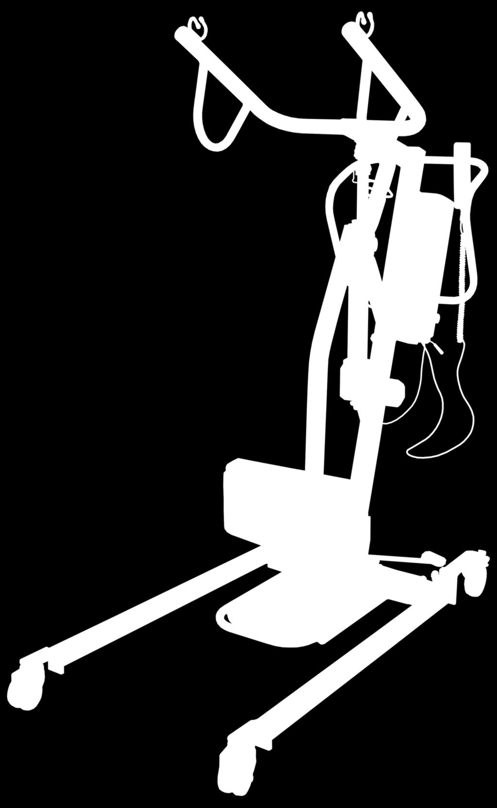
9 5.3 aks-dualo active hoist product overview Mains battery charger Connection cable Active lifting arm Mechanical emergency lowering Lifting arm holder Battery pack Control unit with emergency stop button Standard lifting arm Lift motor shin pad Holder Footboard Chassis Handle Manual control unit Mast Foot pedal for the spreader Rear castor with locking device Front twin castor Figure 03 Page 9
10 5.4 Functional description The aks-dualo is a mobile patient hoist with an electrical lifting and/or standaid function. It is fitted with lifting arms which can be removed without the need for tools and, depending on the application required, can be assembled as a standard hoist for lifting or an active hoist for assisting patients to stand. The U-shaped chassis is equipped with four castors, the rear two of which can be locked. The chassis legs can be spread by pressing a foot pedal. It may be necessary to adapt the chassis legs to the width of the place where the patient is sitting or to increase stability. A mast is mounted on the chassis. This can be folded forwards for transport or storage purposes. An ergonomic handle is attached to the mast to facilitate pushing of the patient hoist. In addition, the control unit and a removable battery pack can also be found on the side of the mast. The lifting arm holder is mounted on the top end of the mast. It can be adjusted using an electric lift motor. The standard lifting arm or active lifting arm respectively can be inserted into the lifting arm holder. The inserted lifting arm is secured with a socket pin to prevent its falling out. The inserted lifting arm is secured with a tube clip against falling out. The pin is attached to the lifting arm holder via a wire to ensure that is does not go missing. The standard lifting arms of the aks-dualo and aks-mini dualo versions are of different lengths. For safety reasons they are designed in such a way that it is not possible to insert them into the wrong hoist. Various aks spreader bars can be mounted on the standard lifting arm. These accept the different aks-slings. The active lifting arm has hooks on it, into which the slings can be hung directly. The aks-dualo active hoist also has a removable footboard with a height-adjustable shin pad affixed to the chassis. The footboard also has a holder for the standard lifting arm not currently in use. The electromotive height adjustment of the lifting arm is performed by a linear motor, which also features a manual emergency lowering. This is controlled using a manual control unit. The required electrical energy is provided by a high performance, removable 24 V battery pack attached to the control unit. This can either be charged on the hoist or using a separate wall charging station. Page 10

. The curved end of the plate slips over the bevel of the bolt.")
11 6 6.1 Assembly Locking plate The aks-patient hoist is equipped with universal bolts and locking plates at several places. These locking plates allow you to mount and remove individual components quickly and without the need for tools, particularly in so far as the assembly and folding away of the hoist is concerned and when mounting or exchanging spreader bars. The correct application and disengaging of the locking plate is described below. Locking plate Applying the locking plate Slide the locking plate into the groove at the end of the bolt (Figure 04). The curved end of the plate slips over the bevel of the bolt. The locking plate is correctly positioned when it clicks into place audibly and can be rotated freely in the bolt s groove. The incorrect and correct positions are shown in Figures 05 and 06 respectively. Universal bolt Figure 04 Incorrect Correct Figure 05 Figure 06 Disengaging the locking plate Retract the curved end of the plate slightly and slide the locking plate out of the bolt s groove (Figure 07). Figure Page 11

.")
. Bolt with locking plate Figure 10 Figure 11 5. 6.")
12 Assembly of the standard hoist To start, place the frame module with the castors on the floor and lock the rear castors (Figure 08). Release the locking plate on the mast holder and pull the bolt out (Figure 09). Bolt with locking plate Figure 08 Figure Pull the mast upright (Figure 10). Reinsert the bolt into the mast holder in order to lock the mast in place. Secure the bolt with the locking plate (Figure 11). Bolt with locking plate Figure 10 Figure Remove the cable tie which holds together the lifting arm holder, the lift motor and the mast for safety reasons during transport. Disengage the locking plate on the upper motor retaining fork of the lifting arm holder and pull the universal bolt out. Page 12
.")
. 9. 10.")
.")
.")
13 7. Swing the lifting arm holder up and secure the lift motor with the universal bolt on the motor retaining fork (Figure 12). Secure the universal bolt with the locking plate (Figure 13). 1 Lifting arm holder Motor retaining fork 2 Universal bolt with locking plate Lift tube Figure 12 Figure Now remove the tube clip from the lifting arm holder. First fold down the clamp on the tube clip (Figure 15) Insert the uncoated end of the standard lifting arm into the lifting arm holder as far as it will go. The lifting arm of the aks-dualo has been designed so that it only fits in the lifting arm holder when correctly orientated (Figure 14). Secure the standard lifting arm using the tube clip. Insert it as far as the stop and fold down the clamp (Figure 15). The tube clip is correctly attached if the clamp encircles the lifting arm tube (Figure 18). Figure 14 Standard lifting arm Lifting arm holder Note: If the tube clip cannot be inserted, this can be caused by the holes not being exactly on top of each other. Pull back the standard lifting arm somewhat until the holes are exactly on top of each other. Figure 15 Standard lifting arm Socket pin Page 13

 and insert the retaining bolt with collar through the spreader bar")

14 The aks patient hoist must only be operated with a correctly attached tube clip! falsch falsch richtig Figure 16 Figure 17 Figure Remove the retaining bolt with collar at the end of the lifting arm for the installation of the spreader bar. Unbutton the padding (as shown in Figure 19) and insert the retaining bolt with collar through the spreader bar from below. Button the padding back up again. Then mount the retaining bolt with collar with spreader bar on the lifting arm. Secure the universal bolt with the locking plate (Figure 20). Padding Retaining bolt with collar Lifting arm Universal bolt with locking plate Standard spreader bar Figure 19 Figure 20 Page 14
.")

15 6.3 Assembling the active hoist Steps 1 to 8 are the same for the assembly of the active hoist as they are for the standard hoist Insert the uncoated end of the active lifting arm into the lifting arm holder as far as it will go (Figure 21). The lifting arm of the aks-dualo has been designed so that it only fits in the lifting arm holder when correctly orientated. Secure the active lifting arm with the socket pin (Figure 22). This is done by pressing the button and retaining it depressed whilst inserting the socket pin as far as it will go. The socket pin is in the correct position if the safety catches on the socket pin are visible on the opposite side (Figure 18). Active lifting arm Lifting arm holder Active lifting arm Socket pin Figure 21 Figure 22 Note: If it is not possible to insert the socket pin even though the button is depressed, it is likely that the holes are not correctly aligned. Retract the active lifting arm slightly until the holes are aligned exactly. The aks-patient hoist must only be operated with a correctly inserted socket pin! 11. Place the footboard on the crossmember of the chassis legs (Figure 23). Shin pad 12. Insert the shin pad into the holder tube on the footboard and secure it in place at the required height using the clamping lever (Figure 23). Clamping lever Footboard Figure 23 Page 15
16 Attaching the aks-calf strap (optional) 13. Loosen the four screws on the shin pad and remove the cushioning (Figure 24). 14. Place the aks-calf strap with the four openings onto the screws of the shin pad (Figure 25). Shin cushioning Screws 15. Now reattach the shin cushioning using the screws (Figure 26). Figure 24 Calf strap Figure 25 Figure 26 Page 16
17 7 Commissioning Please note before commissioning that the Medical Devices Operator Regulations are binding for the operator / user of medical devices. 1. Check the plug connections on the control unit (Figure 26): HS = Manual control unit M1 = Lift motor M2 = not used (blanking plug) AC = Charging socket Charge the battery pack before the aks-patient hoist is used for the first time. To do this, proceed according to Section 8.6 Batteries. Unlock the emergency stop button (Figure 27) if it has been pressed by turning clockwise. Finally, establish the safe condition of the aks-patient hoist using Section 20.2 Maintenance plan. Yellow LED Green LED Emergency stop button Control unit Charging cable Figure 27 Page 17
. The aks-patient hoist can no longer be pushed in this setting.")
18 8 8.1 Operation Parking brake The parking brakes are one of the important safety elements of an aks patient hoist. The rear castors are fitted with parking brakes which act directly on the wheels. To lock the castors, press the parking lever to the stop using your foot (Figure 28). The aks-patient hoist can no longer be pushed in this setting. To release the castors, press the parking lever pointing upwards (Figure 29). When locking the castors always ensure that both castors are locked! If only one castor is locked on a sloping floor, the unlocked wheel will roll downhill around the locked wheel. Depending on the slope of the surface, there is the danger that the aks patient hoist will tip over sideways. Locking lever Locking lever Castor locked Figure 28 Castor released Figure 29 Page 18
.")

19 8.2 Spreader The chassis legs can be spread to increase stability during lifting and lowering. Press the right foot pedal down to spread the chassis legs (Figure 30). Press the left foot pedal down to return the chassis legs to their original parallel position (Figure 31). Moving the aks-patient hoist forwards and backwards gently makes it easier to spread the chassis legs. Ensure there is sufficient clearance from other objects when spreading the chassis legs. There must not be any objects or limbs located in the adjustment range. Foot pedal Foot pedal Figure 30 Figure Emergency stop button The power supply to the motor of your aks-patient hoist is disconnected immediately by pressing the red emergency stop button on the control unit (Figure 32). This function enables you to avoid damage in emergencies. The button is unlocked again by turning it clockwise (direction of arrow). Figure 32 Emergency stop button Page 19
 at the fork head of the motor and turning the lift tube (as seen from above) clockwise. In this way, you lower the patient.")
20 8.4 Mechanical emergency lowering The aks-patient hoist is equipped with mechanical emergency lowering in case of a defect in electrical parts or complete discharge of the battery pack. This is done by folding up the bar (Figure 33) at the fork head of the motor and turning the lift tube (as seen from above) clockwise. In this way, you lower the patient. 2 1 Bar Fork head Lift tube Figure Manual control unit The manual control unit is used to control the lift motor. It is fitted with a rocker switch (Figure 34). Press the left side of the rocker switch (up arrow) to raise the lifting arm and the right side (down arrow) to lower it. Left switch: Raise lifting arm Right switch: Lower lifting arm 8.6 Batteries Figure 34 General The batteries used in the aks-patient hoists are lead gel batteries. These batteries must be permanently charged (similar to a car battery). There is no memory effect for the batteries. A deep discharge damages the batteries so severely that they become unusable. New, freshly charged batteries have a capacity of approx. 40 lifting cycles under full load. Attention: Always charge the batteries in a well ventilated place. Batteries must be completely charged before their first use. Connection Connect the mains battery charger (Figure 35) with the charging cable to the control unit (Figure 36) using the connection cable. Now plug the mains battery charger into a mains power socket with a connection value of 230 V / 50 Hz. Mains battery charger Connection cable Figure 35 Page 20
21 The aks-patient hoist does not function with a mains battery charger connected! For the charging, always connect the mains battery charger to the aks patient hoist first and not to the mains power supply until afterwards. Failure to observe can result in damage to the unit! After the charging, disconnect the mains battery charger from the mains power supply first and then from the aks patient hoist. Indicator lamps on the control unit Green LED The correct connection of the mains battery charger to the control unit is indicated by the green LED on the control unit (Figure 36). If the green LED does not light, there is no charging voltage present, i.e., the mains battery charger or the connection is defective. Yellow LED Yellow LED Green LED Charging cable The yellow LED indicates the charging process (Figure 36). It also lights every time the mains Figure 36 battery charger is connected. When the batteries are completely charged, the yellow LED goes out and the mains battery charger automatically switches to standby mode. If the battery capacity is less than a specified value after some time, the mains battery charge switches on again automatically and the yellow indicator lamp is lit again. If the batteries are almost fully charged, the yellow indicator may flash for a short time. This is not a fault. Charging time and capacity indicator lamp on the manual control unit The batteries of the aks-patient hoist should always be charged when not in use. Depending on the condition of the batteries, the charging process can take up to 24 hours, however 12 hours are usually sufficient. The batteries should be completely charged at least once per month in order to avoid a deep discharge, which can result in the destruction of the batteries. If the battery capacity drops below a minimum value, when the switch is pressed the capacity indicator lamp on the manual control unit (Figure 37) changes from green to red and a warning tone is given at the same time. In this case, the batteries must be charged immediately. Figure 37 Capacity indicator lamp (green / red) When red Page 21
22 When the green capacity indicator on the manual control unit is lit and the batteries are connected for charging, it only takes a few hours for the batteries to be fully charged again (fast charge). If the manual control unit indicator changes from green to red, the aks-patient hoist must not be operated further. A lifting cycle already started can, of course, be completed. Further operation in this condition (i.e., capacity indicator lamp lit red) results in a deep discharge and can thus result in damage to the batteries. If the batteries are now connected for charging, the charging voltage is reduced for the protection of the batteries. In this condition, the charging time is significantly increased (up to max. 3 days). If the batteries are not completely charged after 3 days, they are defective and must be replaced. Do not use the aks-patient hoist any more for lifting if the capacity control indicator is lit red or if a warning tone sounds during manual control. Failure to observe may damage the batteries. Removing and inserting the battery pack The battery pack on the aks-patient hoist can be removed without the need for tools. This gives you the possibility to exchange the battery pack quickly or charge it separately in a wall charging station Insert your fingers into the recessed grip on the battery pack from above and pull the unlocking lever upwards (Figure 38). Simultaneously pull the battery pack off the mounting rail and then upwards and out of the holder (Figure 38). To insert, repeat the process in the reverse order. Ensure that the unlocking lever clicks into place in the mounting rail and the battery pack lies securely flush to the mounting rail (Figure 39). Recessed grip with unlocking lever Battery pack Mounting rail Control unit Figure 38 Correct Incorrect Figure 39 Figure 40 Page 22
23 8.7 Exchanging the lifting arm on the standard hoist If you wish to convert the aks-dualo from a standard hoist to an active hoist you need the active lifting arm and the footboard with the installed shin pad. Proceed as follows: Remove the tube clip from the lifting arm holder (Figure 41). Remove the standard lifting arm from the lifting arm holder and place it to one side (Figure 41). Insert the active lifting arm into the lifting arm holder (Figure 42). Secure the active lifting arm using the tube clip (Figure 42) Figure 41 Figure Affix the footboard on the chassis by clipping it in onto the crossmember using the brackets (Figure 43). Insert the removed standard lifting arm into the holder provided for it on the footboard (Figure 44). Figure 43 Figure 44 Page 23
. Remove the active lifting arm from the lifting arm holder and place it to one side (Figure 45).")
24 8.8 Exchanging the lifting arm on the active hoist If you wish to convert the aks-dualo from an active hoist to a standard hoist you need the standard lifting arm and a suitable aks-spreader bar. Proceed as follows: Remove the socket pin from the lifting arm holder (Figure 45). Remove the active lifting arm from the lifting arm holder and place it to one side (Figure 45). Insert the standard lifting arm in the lifting arm holder (Figure 46). Secure the standard lifting arm with the socket pin (Figure 46) Figure 45 Figure Remove the footboard from the chassis (Figure 47). Store the removed active lifting arm and the footboard in a suitable location. Figure 47 Page 24

.")

25 8.9 Folding up the hoist The aks-dualo can be folded up for transport purposes or space-saving storage. To do this it is necessary to remove the spreader bar from the standard hoist and the active lifting arm and footboard with the shin pad from the active hoist. Afterwards, proceed as follows: Remove the locking plate and the universal bolt on the lifting arm holder (Figure 48). Swing the motor first followed by the lifting arm holder or standard lifting arm up to the mast (Figure 49). Affix the motor and lifting arm holder or standard lifting arm to the mast using a cable tie or Velcro strip. Lifting arm 2 Motor retaining plate Universal bolt with locking plate 1 Lift tube Figure 48 Figure Now remove the locking plate with the bolt on the mast holder and fold the mast forwards (Figure 50). Then lock it in the mast holder using the bolt and the locking plate (Figure 51). Figure 50 Universal bolt with locking plate Figure 51 Page 25
26 9 9.1 Patient transport Safety instructions Observe the following safety instructions before every lifting / assisting to stand and conveying of the patient: The member of care staff (user) must have the corresponding expert knowledge to select and use a suitable aks-sling. For use as a standard hoist, check the permissibility of the combination of spreader bar and sling before use based on the Table 04 in Chapter 10 Accessories/ Combinations. Check the correct sling size and sling form in relation to the patient. Check the safe condition of the sling before every use. The sling must have neither tears in the material nor damaged seams. Check whether the correct loop combination has been attached. All loops have 3 different mounting levels: long - medium - short. Each loop pair (e.g., leg loops, shoulder loops, etc.) must only show the following mounting combination: long - long, medium - medium or short - short. Check whether all loops are mounted in the hooks. Lock the wheels of the wheelchair, homecare bed, stretcher etc., in order to be able to raise and lower the patient safely. In doing so, leave the castors of the aks-patient hoist unbraked. Plan the patient transport to be as short as possible and never leave the patient unsupervised when suspended in the sling or positioned on the footboard. Supervise the patient during the transfer. Sharp movements of the patient or holding on to objects during the transfer can pose risks. Only lift the patient as high as is necessary. Ensure that the patient is positioned stably on the footboard when using the active hoist to assist him to stand and transport him. Employ a calf strap if necessary. Keep the hoist slings away from extreme heat and naked flames; they are not flame-retardent. Page 26

27 9.2 Patient transport with standard hoist In order to lift and convey a patient with the aks-dualo, it must be assembled as a standard hoist. Further prerequisites for this use are a suitable aks-spreader bar and suitable aks-sling. The type and size of the sling always depends on the stature of the patient and the type of use. aks provides several different spreader bars and a wide range of slings (see Chapter (10 Accessories/Combinations) which are adapted to the respective requirements. The attachment of an aks-standard sling (Figure 52) in combination with an aks-standard spreader bar on a patient in the lying position is described below. aks-standard sling Shoulder loop Manoeuvring handle Back panel of sling Leg strap Leg loop Figure If the patient is lying on his back, roll him on to his side so that he is facing away from you. Fold the aks-standard sling in half down the middle. Place the aks-standard sling with the folded side down the back of the patient. When doing so, the aks logo and the labels must face downwards. Ensure that the bottom edge of the back panel of the sling reaches the coccyx and the top edge is at the patient's shoulders. Now roll the patient back over the aks-standard sling on to his other side. Now pull the folded half of the aks-standard sling under the patient and position it correctly Return the patient to his back. The patient is lying correctly on the aks-standard sling if his back is completely on the back panel of the sling and the leg straps are next to the thighs. Now raise the back part of the homecare bed until the patient is sitting almost upright. Page 27

28 Pass the leg straps from the outside to the inside around the patient's respective thighs. Position your aks-patient hoist with the aks-standard spreader bar so that the aks-standard spreader bar is at eye level in front of the patient. Ensure that the aks-standard spreader bar is not too close to the patient's face. Before attaching the sling to the spreader bar make sure that both the shoulder loops and both the leg loops are at the same height. Now hang both the shoulder loops on the outer hooks of the aks-standard spreader bar. Then hang both the leg loops crossed over on the inner hooks. Raise the lifting arm of the aks-patient hoist somewhat until the leg and shoulder loops become taut. Now check whether the aks-standard sling is attached correctly and comfortably. You can now lift the patient. Use the manoeuvring handle located on the top edge of the back panel of the sling for easier manoeuvring. 9.3 Patient transport with active hoist In order to assist a patient to stand and convey a patient with the aks-dualo, it must be assembled as an active hoist. A suitable aks-standaid sling is also needed for this application. The size of the sling always depends on the patient's stature. Attaching an aks-standaid sling with chest loop (Figure 53) in combination with the aks-calf strap and the bringing of a seated patient to a standing position from a chair are described below: aks standaid sling with chest loop Underarm padding Sling loop Chest loop Figure 53 Page 28
29 Undo the Velcro on the chest loop on the aks-standaid sling and place the sling behind the patient. The stuck-on aks logo must be visible on the outside from behind and the underarm pads must be nestled in the armpits. Close the chest loop over the patient's chest with the Velcro. Now spread the chassis legs of the akspatient hoist and position it in front of the patient. Ensure that the patient lifts his feet beforehand. The akspatient hoist is orientated correctly if Figure 54 the patient's feet are comfortably and completely positioned on the footplate of the footboard. Knee pad Calf strap (optional) Clamping lever Footplate Release the clamping lever on the shin pad and adjust the correct height of the shin pad (Figure 54). The top edge of the shin pad must be just below the patient's kneecaps. Undo the Velcro on the aks-calf strap and place this around the patient's calves. Close the Velcro again. Now lower the lifting arm if necessary and attach both sling loops of the aks-standaid sling to the hooks of the lifting arm. Raise the lifting arm of the aks-patient hoist somewhat until the sling loops become taut. Now check whether the aks-standaid sling is attached correctly and comfortably. The patient must now grasp the handles of the lifting arm tightly with both hands. You can now assist the patient to stand and transport him to the desired place. Page 29
30 10 Accessories / Combinations Only use original aks accessory parts as accessories as they have been tested by us and guarantee faultless and safe functioning. Accessories: Table 02 Accessories Order no. Standard spreader bar, including padding Spreader bar for lying position, including padding Spreader bar for lying position with 8-point attachment Spreader bar padding Charger unit Battery pack Wall charging station for battery pack aks-dw 150 (digital hoist scales with adapter, adjustable) aks-efw 150 (calibratable hoist scales with adapter and standard spreader bar) Head support for the standard sling and bath sling Calf strap See Table 04 for other hoist slings Combinations: The aks-dualo is of modular construction. It is easy to convert your hoist to a new product with a minimum of effort. Replace the existing lifting arm with the corresponding conversion set. The combination possibilities are given in Table 03. Table 03 Existing product Conversion set Order no. New product aks-dualo standard hoist aks-dualo/mini dualo active lifting arm (incl. footboard and aks-dualo active hoist shin pad) aks-mini dualo standard hoist aks-dualo/mini dualo active lifting arm (incl. footboard and aks-mini dualo active hoist shin pad) aks-dualo active hoist aks-dualo standard lifting arm aks-dualo standard hoist aks-mini dualo active hoist aks-mini dualo standard lifting arm aks-mini dualo standard hoist The combinations tested and approved by us for using an aks-sling with an aks-spreader bar are summarised in Table 04. The user must have the corresponding expert knowledge to be able to assess the suitability of the sling for the patient and the application correctly. Page 30
31 Product Application / posture S = sitting L = lying A = for assisting to stand Table 04 Standard spreader bar Spreader bar for lying position Spreader bar for lying postion (with 8 hooks) Standard sling S x x - Standard sling with back reinforcement and head support Comfort sling with integrated head support S x x - S x x - Bath sling S x x - Bath sling with back reinforcement and integrated head support Comfort bath sling with integrated head support S x x - S x x - Order no. (sorted by size) (S) (M) (L) (XL) (XXL) (S) (M) (L) (S) (M) (L) (XL) (XXL) (S) (M) (L) (XL) (XXL) (S) (M) (L) (S) (M) (L) (XL) (XXL) Bath sling aqua blue S x x (M) (S) Hygienic sling S x x (M) (L) (S) Comfort / hygienic sling S x x (M) (L) Rapid transport sling with chest loop S x x (S) (M) (L) Sling for lying position L - x (M) Sling for lying position, 8-point attachment (without filling material) Seat sling for patients with amputated limbs (without filling material) Bath sling for patients with amputated limbs L - - x S x - - L x (M) (L) (XL) (XXL) (M) (L) (M) (L) Standaid sling (2 single slings) S x (M) Standaid sling with chest loop (can only be used with active hoists) A (M) (L) (XL) (XXL) Page 31
32 11 Troubleshooting / fault clearance Should a fault occur and the aks-patient hoist no longer function, check the fault using Table 05. If the cause of the fault cannot be established and corrected, inform your aks authorised dealer. Table 05 Fault Possible causes Action Emergency stop button pressed Unlock emergency stop button Manual control unit cable not plugged in or plugged in Plug in manual control unit cable aks-patient hoist does not lift incorrectly (LED on the manual control unit does not light) aks-patient hoist does not lift (LED on the manual control unit lights green) aks-patient hoist does not lift Hoist connected to charger unit Battery pack discharged Battery pack defective Motor cable not plugged in or plugged in incorrectly Battery pack discharged Wait until the charging process is complete, then disconnect the charger unit from the hoist Charge battery pack Replace battery pack Plug in motor cable Charge battery pack (LED on the manual control lights red) Battery is not charged (green LED on the manual control does not light) Battery pack defective No correct connection between charging cable and mains battery charger Connection cable or mains battery charger defective Replace battery pack Check plug connections Replace defective part Page 32
33 12 Care / cleaning The aks-patient hoist can be cleaned manually using a damp cloth. Cleaning and care materials suitable for plastic furniture can be used as cleaning materials. Thereby, observe the following points: Do not use any abrasive agents or cleaning materials containing ammonium chloride. Only use dermatologically tested materials. Do not use any basic and alkaline cleaning agents. Do not use any aggressive cleaning agents (e.g., solvents) or hard brushes etc. Do not dip the electrical components in water; clean these with a barely damp cloth. Only use alcohol-free and chlorine-free disinfectants and methods from the RKI (Robert-Koch Institut) list or the disinfectants list of the VAH (Verbund für Angewandte Hygiene e.v.) for spraying and wiping disinfection. Observe the instructions and safety precautions from the manufacturers of the cleaning and disinfectant materials. Never clean the aks-patient hoist, especially the electrical system, with a high pressure cleaner, water hose or similar because doing so could damage the surfaces and seals, and water could enter. Page 33
34 13 When not in use If the aks-patient hoist is not needed, it should always be connected to the mains battery charger in order to ensure the full capacity of the batteries for the next use. The integrated charging electronics prevent overcharging of the batteries and switch to trickle charging when the batteries are completely charged. Always charge the batteries in a well ventilated place. 14 Storage Store the aks-patient hoist in as cool and dry a place as possible. The ambient conditions of the storage location should be at an ambient temperature of between 0 C and 40 C, humidity of between 20% and 80% and air pressure of between 700 hpa and 1060 hpa. Avoid direct sunlight. Use the original packaging for the storage. In the case of long periods of storage, it must be ensured that the batteries are completely charged at least once per month to avoid a possible deep discharge. A deep discharge results in destruction of the batteries. 15 Reuse The aks-dualo patient hoist is suitable for repeated use. The aks-patient hoist must be cleaned, disinfected and serviced according to Chapter 20 Maintenance at the very latest just before the reuse. Page 34
35 16 Service life The service life of the aks-patient hoist is largely dependent on the quantity of lifting procedures performed each day, the device s being used correctly and regular maintenance. The aks-patient hoist has been tested for long-term functional capacity with 11,000 lift procedures according to DIN EN ISO Please note that the factory warranty of your aks-patient hoist is valid for 24 months from the date of purchase (see Chapter 18 Guarantee). 17 Disposal If the aks-patient hoist has outlived its purpose, the electrical components must be treated as waste electrical equipment according to the WEEE Directive (Waste Electrical and Electronic Equipment) and disposed of properly. This is indicated by the symbol in Figure 55. In the case of electrical equipment brought into circulation as new equipment after 13/08/2005, the owner is legally obliged not to give their electrical components to municipal collecting points but to return them directly to the manufacturer. Our General Terms and Conditions are applicable for the return. Unusable batteries must not be disposed of in domestic waste. These must be disposed of in accordance with the regulations for the return and disposal of used batteries. The used plastic and metal parts of the aks-dualo must be disposed of separately and properly. Contact your local disposal company for this. Figure 55 Page 35
36 18 Warranty The aks-dualo and aks-mini dualo aks-patient hoists are distinguished by their long service lives and high reliability. Nevertheless, should technical problems arise which cannot be rectified with the measures from Chapter 11 Troubleshooting / Fault clearance, please contact your local authorised dealer. The dealer will provide assistance as quickly as possible and acquire all necessary spare parts if required. We guarantee our aks-patient hoists for faultless condition in the context of our delivery and payment conditions. We offer a factory warranty for material defects of 24 months from the date of purchase. We reserve the right to make technical changes for the purpose of improvement. Please refer to the rating plate on the lower end of the mast for the model designation and serial number. Failure to observe the operating instructions, improperly carried out maintenance work and technical modifications and additions (attachments) without the permission of aks void the warranty and the general product liability. In the case of change of owner of the aks-patient hoist, please pass on this operating manual. 19 Declaration of conformity All aks-patient hoists in the aks-dualo series comply with the applicable requirements of the EU Council Directive 93/42/EEC Medical Devices taking account of the amending Directive 2007/47/EC. The following norms were employed in its development: EN Medical electrical equipment - Part 1 : General requirements for basic safety and essential performance EN Medical electrical equipment - Part 1-2: General requirements for basic safety and essential performance - Collateral standard: Electromagnetic compatibility - Requirements and tests EN ISO Hoists for the transfer of disabled persons - Requirements and test methods EN Assistive products for persons with disability General requirements and test methods Page 36
37 Maintenance General maintenance instructions The service life of the patient hoist is basically influenced by the handling. In order to ensure safe operation, a visual inspection and functional check according to the maintenance plan must be carried out at least annually by suitable qualified personnel. If the patient hoist is not regularly maintained properly, safe use is no longer guaranteed. Wear, damage or also loosening of connecting elements can thus not be detected. The Medical Products law (MPG) and the Medical Products Operator Regulations are applicable in Germany. The corresponding national requirements are applicable in other countries. EN in the respective current version must be used as test specification for this medical product. In the case of damage to load-bearing parts, electrical cables or parts of the electrical system, the patient hoist must no longer be used. Press the emergency stop button and remove the battery pack. In the case of damage and defects, inform your authorised dealer who will replace these parts. Connection or disconnection of electrical components must only be done when the power supply is disconnected. Press the emergency stop button for this. Only original aks spare parts and aks accessories which have been approved for this product are permitted to be used, otherwise any warranty and product liability are excluded. You must not make any technical modifications and additions without permission from aks. Page 37
38 20.2 Maintenance schedule The maintenance must be performed at least annually and before each reuse according to EN The slings must be serviced at least every 6 months according to EN ISO Pos. Check point ok 1 Check of the basic requirements 1.1 Appropriate and safe use 1.2 Permitted accessories or equipment combination 1.3 Rating plate, stickers and warnings present 1.4 Presence of operating manual 2 Visual inspection of spreader bar 2.1 No damage (general condition) 3 Visual inspection sling 3.1 No damage (general condition) 3.2 No severe localised wear or tears, holes or burn marks in the material 3.3 No soiling/damage induced by chemical agents 3.4 No seams with unpicked, worn, pulled out or ripped stitches. 4 Visual inspection standard lifting arm 4.1 No damage (general condition) 4.2 Universal bolt with locking plate (replace in the case of signs of wear, e.g., embedding) 4.3 Retaining bolt with collar of spreader bar (replace in the case of wear, e.g., embedding; the collar height must be at least 4 mm) 5 Visual inspection active lifting arm 5.1 No damage (general condition) 5.2 All plastic caps (4x) and plugs (2x) are present 6 Visual inspection footboard 6.1 Clamping lever present 6.2 Footboard with rubber mat undamaged and securely in place 6.3 Cushioning on shin pad undamaged and securely in place 6.4 Square stoppers present on the shin pad 7 Visual inspection of frame 7.1 Castors undamaged 7.2 Spreader mechanism (both rubber caps present on the foot pedal) 7.3 Universal bolt with locking plate (replace in the case of signs of wear, e.g., embedding) 7.4 Drive (fork fixing, lift tube fixing with universal bolt and locking plate) 7.5 Tube clip connected with the wire is available 8 Visual inspection of general condition of patient hoist (complete) 8.1 No improper handling 8.2 No wear or abrasion 8.3 No unauthorised interventions or modifications 8.4 No soiling (in particular the lift tubes) 8.5 No surface damage or corrosion 9 Weld seams / deformation of patient hoist (complete) 9.1 Chassis 9.2 Mast 9.3 Lifting arm holder 9.4 Standard lifting arm or active lifting arm 9.5 Footboard with shin pad 9.6 Spreader bar Page 38
39 10 Threaded connections of patient hoist (complete) 10.1 Castors: All fixing screws and nuts are tight 10.2 Chassis: All fixing screws and nuts are tight 10.3 Spreader: All fixing screws and nuts are tight 10.4 Mast: Fixing screw and nut between the mast and chassis are tight 10.5 Lifting arm holder: Fixing screw and nut between the lifting arm holder and mast are tight 10.6 Mounting rail for battery pack and control unit: Both fixing screws are tight 11 Inspection of the electric parts of the patient hoist (complete) 11.1 Case (drive(s), control unit, battery pack, manual control unit) 11.2 Cables (manual control unit cable, charging cable, plug connections with sealing ring) 11.3 Mains battery charger (connector, cable, case, rating plate / lettering) 11.4 Indicator lamp in the manual control unit (green = battery capacity OK; red + acoustic alarm = below fast charge limit) 11.5 Mains battery charger connection (green LED indicates the proper connection of the mains battery charger) 11.6 Charging indicator (yellow LED shows the charging process) 11.7 Note service life of the batteries (batteries must be replaced after 4 years at the latest) 12 Functional inspection of patient hoist (complete) 12.1 All castors can be turned in any direction easily and rotate 360 without a problem 12.2 Both lockable breaks can be locked and unlocked easily 12.3 The battery pack can be removed and reinserted without a problem 12.4 The chassis legs can be spread to the foreseen width with the foot pedal (Dimension p in Section 21.2 Data) and returned to parallel 12.5 The emergency stop button can be depressed and clicks in; it overrides every other electrically activated adjustment 12.6 The emergency stop button can be unlocked by turning clockwise 12.7 The mechanical emergency lowering functions correctly 12.8 The tube clip can be used as intended; the clamp can be folded into the open / closed position 12.9 The shin pad can be adjusted for height without a problem and fixed in position with the clamping lever The lifting arm(s) can only be inserted correctly in one position, removed and secured with the tube clip The lifting arm(s) can be electrically adjusted without loading across the whole lifting range (dimension m in Section 21.2 Data) and stop(s) in both end positions (dimension l and k in Section 21.2 Data) The lifting arm(s) can be electrically adjusted with the maximum load of 150 kg across the whole lifting range (dimension m in Section 21.2 Data); self-locking present Patient hoist is in full working order: Inspector: Overall assessment of patient hoist Yes No Date of inspection: Signature: Company: aks-dualo frame: Components used Serial no. or date of manufacture Next service aks-mini dualo frame: aks-dualo standard lifting arm aks-mini dualo standard lifting arm aks-dualo/mini dualo active lifting arm: aks-dualo/mini dualo footboard: Spreader bar (please record model here): Sling (please record model here): Page 39


40 21 Technical data 21.1 Rating plates and stickers Figure Page 40

41 Table 06 Rating plates and stickers Pos. Pos. Typ: Modell: Bauteil: Patientenlifter aks-dualo Hebearm standard 1 2 Serien-Nr.: SN Maximallast 150 kg C aks-dualo Typ: Modell: Bauteil: Patientenlifter aks-mini dualo Hebearm standard aks-dualo aks-mini dualo Serien-Nr.: SN Maximallast 150 kg C aks-mini dualo 3 Typ: Modell: Bauteil: Patientenlifter aks-dualo / mini dualo Hebearm aktiv Serien-Nr.: SN Typ: Modell: Bauteil: Patientenlifter aks-dualo / mini dualo Trittbrett Serien-Nr.: SN Maximallast 150 kg C Maximallast 150 kg C 5 6 Date of manufacture 7 Maximallast 150 kg 8 ACHTUNG! Den Bolzen mit der SL-Sicherung sichern. 9 ACHTUNG! Betätigung des Steckbolzens nur durch eingewiesenes Fachpersonal. Page 41
aks-clino II Patient hoist Operating manual
 Patient hoist Operating manual Date: 2011_12 Page 2 TABLE OF CONTENTS 1 Introduction 4 2 Intended purpose 5 3 General safety instructions 6 4 Scope of delivery 7 5 Product description 8 6 Assembly 10 7
aks-goliath Operating manual (translation of the original operating manual)
") Operating manual (translation of the original operating manual) Date: 03/2007 Dear Customer, thank you for purchasing our hoist. You have acquired a functional hoist with simple handling and the highest
Operating manual (translation of the original operating manual) Date: 03/2007 Dear Customer, thank you for purchasing our hoist. You have acquired a functional hoist with simple handling and the highest
aks-efw 300 Fastening set with weighing hanger for hoist scales with EC calibration Operating manual (translation of the original operating manual)
") Fastening set with weighing hanger for hoist scales with EC calibration Operating manual (translation of the original operating manual) Date: 2012_01 Page 2 TABLE OF CONTENTS 1 Introduction 4 2 Intended
Fastening set with weighing hanger for hoist scales with EC calibration Operating manual (translation of the original operating manual) Date: 2012_01 Page 2 TABLE OF CONTENTS 1 Introduction 4 2 Intended
AQUATEC R / AQUATEC F / AQUATEC XL. Bathlift Operating instructions
 AQUATEC R / AQUATEC F / AQUATEC XL Bathlift Operating instructions 1 2 3 4 5 6 7 8 9 10 11 Contents 1 General instructions................. 3 1.1 Introduction......................... 3 1.2 Proper use.........................
Liko M220 / Liko M230
 Liko M220 / Liko M230 Instruction Guide English 7EN150106-04 2012-03-06 Applies to the following models: Liko M220 Prod. no. 2050010 Liko M230 Prod. no. 2050015 Liko M230 Product Description Liko M220
All-in-One Hoist User Manual , , ,
 All-in-One Hoist User Manual 25-20010, 25-20020, 25-20030 25-20040, 25-20050 PDF 5946 Nov-2010 General about the hoist Index General about the hoist 3 Operation Operating instructions 4 Battery charging
Operating instructions ErgoPack 600 E
 Operating instructions ErgoPack 600 E Operation of the device is only permitted if the operating instructions have been carefully read and understood before use! Declaration of conformity EU declaration
Molift Mover 180. EN - User manual. BM08101 Rev. D
 Molift Mover 180 EN - User manual BM08101 Rev. D 2016-04-01 English manual Content Molift Mover 180...2 Lifter components...2 About Molift Mover 180...2 General...3 Declaration of conformity...3 Conditions
Molift Mover 300. EN - User manual. BM06101 Rev. F
 Molift Mover 300 EN - User manual BM06101 Rev. F 2016-06-01 English Manual Content Molift Mover 300...2 Lifter components...2 About Molift Mover 300...2 General...3 Declaration of conformity...3 Conditions
USER MANUAL PRODUCT CODE: WC CareCo (UK) Ltd, Hubert Road, Brentwood, Essex, CM14 4JE PAGE 1
 Ltd, Hubert Road, Brentwood, Essex, CM14 4JE PAGE 1") by USER MANUAL PRODUCT CODE: WC01059 CareCo (UK) Ltd, Hubert Road, Brentwood, Essex, CM14 4JE PAGE 1 CONTENTS 1. INTRODUCTION 2. IDENTIFICATION OF PARTS 3. SAFETY REGULATIONS 4. SAFETY WARNINGS 5. USER
by USER MANUAL PRODUCT CODE: WC01059 CareCo (UK) Ltd, Hubert Road, Brentwood, Essex, CM14 4JE PAGE 1 CONTENTS 1. INTRODUCTION 2. IDENTIFICATION OF PARTS 3. SAFETY REGULATIONS 4. SAFETY WARNINGS 5. USER
Drive Unit e-drive1. Installation instructions 04/2014. English translation of the original German installation instructions
 Drive Unit e-drive1 Installation instructions 04/2014 English translation of the original German installation instructions Contents Foreword... 3 Availability... 3 Structural features in the text... 3
Installation and operating instructions. Solar charge controller MPPT 10 A / 20 A Z Z
 Installation and operating instructions Solar charge controller MPPT 10 A / 20 A EN 1 Contents 1. About these instructions... 3 1.1 Applicability... 3 1.2 Users... 3 1.3 Description of symbols... 3 2.
Pallas/150. Stand-aid lifter. User instruction. Important - information. This user instruction must be read before the Pallas 150 is used.
 Pallas/150 Stand-aid lifter User instruction Important - information This user instruction must be read before the Pallas 150 is used. This user instruction is intended for technicians, installers, therapists
SGA-440 by Prism Medical
 SGA-440 by Prism Medical Introduction... 2 Overview... 2 Components of the Sit to Stand Lift... 3 Component List... 4 Specifications... 5 Cautions... 6 Assembly Instruction... 7 Operation Charging......12
Molift Mover 205. EN - User manual. BM05101 Rev. L
 Molift Mover 205 EN - User manual BM05101 Rev. L 2016-04-01 English Manual Content Molift Mover 205...2 Lifter components...2 About Molift Mover 205...2 General...3 Declaration of conformity...3 Conditions
Oxford. Manufacturer s Contact Details. Contents. Oxford Presence. English
 English Manufacturer s Contact Details EUROPE Joerns Healthcare Limited Drakes Broughton Business Park, Worcester Road Drakes Broughton, Pershore, Worcestershire WR10 2AG United Kingdom Tel: 0844 811 1156
Molift Partner 255. EN - User manual. BM03101 Rev. L
 Molift Partner 255 EN - User manual BM03101 Rev. L 2016-06-14 English Manual Content Molift Partner 255...2 Lifter components...2 About Molift Partner 255...2 General...3 Declaration of conformity...3
Owners Manual Unilift
 Owners Manual Unilift Contents Chapter Page Introduction 2 Safety Advise 3 Warranty 4 Using the Unilift 5 Fitting the Sling 6 Lifting and lowering 7 Emergency Controls 8 Battery and Charging Systems 9
KeContact P20. User manual
 KeContact P20 User manual Comments to this manual In this manual you will find warnings against possible dangerous situations. The used symbols apply to the following meanings:!! WARNING! Indicates a potentially
D Dräger Alcotest 3000 Breath Alcohol Measuring Device
 D Dräger Alcotest 3000 Breath Alcohol Measuring Device Instructions for Use ST-14138-2008_sw.eps Table of Contents For Your Safety....................................... 3 Intended Use..........................................
User Manual Operator chair Carl Mk2
 User Manual Operator chair Carl Mk2 - Model R5 - Easy - Model R6 - Rilis - Model R7 - OneGrip - Model R8 - FlexiDoc - 2011-0058 v6 Table of content 1. Operator chair Carl Mk2... 3 2. Important Before Use...
Instruction manual. RP800 - HYDRAULIC actuator, load 150Kg. RP815 - LINAK actuator, load 150Kg
 HYDRAULIC patient lift RP800 - HYDRAULIC actuator, load 150Kg MA RP800_805_806_ 807_810_811_815 02 A_12-2010 Electric patient lifts RP805 - LINAK actuator, load 150Kg RP806 - HIWIN actuator, load 150Kg
User manual. Model Mini, Small, Medium and Large
 User manual Model Mini, Small, Medium and Large 2 Contents Introduction..3 CE marking and labels...3 Safety precautions..3 Prior to first use 4 Meywalk 4 parts...4 Joining the top part and bottom frame.5
PRISM MEDICAL UK SA160C STAND AID
 PRISM MEDICAL UK SA160C STAND AID USER GUIDE Unit 1, Tir Llwyd Industrial Estate, St Asaph Avenue, Kinmel Bay, Nr Rhyl, Conwy, LL18 5JZ info@prismmedical.co.uk Tel +44 (0)1924 840100 www.prismmedical.co.uk
Visual inspection Inspect lift functions regularly. Check to ensure that material is free from damage.
 MiniLift200 Manual The MiniLift200 is an electrically powered stand-up lifter for people with impaired mobility and strength and who are unable to stand up unassisted. The MiniLift200 is designed for indoor
MADITA-Fun mini. the therapy chair for initial assistance. Instructions for use
 MDIT-Fun mini the therapy chair for initial assistance Instructions for use Dear Customer, t this point we would like to thank you for placing your trust in our company and for purchasing our product.
Free Standing Track. Owner s Manual. Use and Care Trouble Shooting
 Free Standing Track Owner s Manual Use and Care Trouble Shooting VANCARE, INC. 1515 1ST STREET, AURORA, NE 68818 T (800) 694-4525 F (402) 694-3994 info@vancare.com www.vancare.com Table of Contents Free
EZ Way Shower Trolleys
 EZ Way Shower Trolleys 2000/3000 Operator s Instructions EZ Way, Inc. PO Box 89 Clarinda, IA 51632 1-800-627-8940 www.ezlifts.com Form 2-207 Rev. 12/14/11 The EZ Way Shower trolley is unique with its side-mounted
OPERATION & MAINTENANCE INSTRUCTIONS
 AUTOMATIC BATTERY CHARGER / MAINTAINER MODEL NO: CBO9-6/12 PART NO: 6267020 OPERATION & MAINTENANCE INSTRUCTIONS LS0615 INTRODUCTION Thank you for purchasing this CLARKE product. Before attempting to use
U S E R M A N U A L. To avoid injury, read user manual prior to use. enablelifecare.com.au. Hoyer Journey. Joerns Hoyer Presence
 U S E R M A N U A L Hoyer Journey To avoid injury, read user manual prior to use. enablelifecare.com.au Contents 1. The Hoyer Journey Patient Lift... 3 2. Introduction: About Your Lift... 4 3. Assembly
Table of contents 1 Introduction 2 Suitability 3 General safety instructions 4 Adjustments 24 5 Seat location selection and adjustment
 Table of contents...... 1 Introduction................................. 20 2 Suitability.................................. 20 3 General safety instructions....................... 21 4 Adjustments.................................
User Manual TABLE MAGNIFIER TL-70. User-friendly Manual ID: #05007
 User Manual TABLE MAGNIFIER TL-70 MANUAL DEVELOPED IN GERMANY myhansecontrol.com User-friendly Manual ID: #05007 Contents Overview... 4 Device parts... 5 Scope of delivery/device parts...6 Preface... 7
OPERATION & MAINTENANCE INSTRUCTIONS
 AUTOMATIC BATTERY CHARGER / MAINTAINER MODEL NO: CBO9-12 PART NO: 6267025 OPERATION & MAINTENANCE INSTRUCTIONS LS0315 INTRODUCTION Thank you for purchasing this CLARKE product. Before attempting to use
OPERATION & MAINTENANCE INSTRUCTIONS
 AUTOMATIC BATTERY CHARGER / MAINTAINER MODEL NO: CBO9-12 PART NO: 6267025 OPERATION & MAINTENANCE INSTRUCTIONS ORIGINAL INSTRUCTIONS LS0118 - ISS 3 INTRODUCTION Thank you for purchasing this CLARKE product.
Armon Edero. User manual
 User manual Armon Edero Foreword.... 2 Symbols used 2 Intended use.... 2 About the Armon Edero... 2 Mounting options of the Edero 2 Braces. 3 How to set up the Armon Edero.. 3 How to attach the brace to
USER MANUAL. CareCo (UK) Ltd, Hubert Road, Brentwood, Essex, CM14 4JE PAGE 1 PRODUCT CODE WC01060.BLU
 Ltd, Hubert Road, Brentwood, Essex, CM14 4JE PAGE 1 PRODUCT CODE WC01060.BLU") by USER MANUAL PRODUCT CODE WC01060.BLU PAGE 1 CareCo (UK) Ltd, Hubert Road, Brentwood, Essex, CM14 4JE INFORMATION Thank you for purchasing a wheelchair from I-GO. This I-GO wheelchair has been designed
by USER MANUAL PRODUCT CODE WC01060.BLU PAGE 1 CareCo (UK) Ltd, Hubert Road, Brentwood, Essex, CM14 4JE INFORMATION Thank you for purchasing a wheelchair from I-GO. This I-GO wheelchair has been designed
GARDENA. N FIN P E I DK S NL F GB D
 GARDENA AccuCut 400 Li Art. 8840 D Betriebsanleitung Operating Instructions F Mode d emploi Coupe bordures NL Instructies voor gebruik S Bruksanvisning freeetrim DK Brugsanvisning freeetrim I Istruzioni
Prism A-205. Owner s Manual. Aluminium Mobile Hoist. Use and Care Trouble Shooting Warranty Information. Introduction Overview...
 Prism A-205 Aluminium Mobile Hoist Introduction... 2 Overview... 2 Components of the Mobile hoist... 3 Component List... 4 Specifications... 5 Cautions... 6 Assembly Instruction... 7 Operation Charging......13
Ensure the product has been assembled according to the instructions in this manual.
 ConvaQuip S I T - T O - S T A N D L I F T MODELS ConvaQuip STS600E ConvaQuip STS600E-D PRODUCT FEATURES *ConvaQuip STS600E shown Ensure the product has been assembled according to the instructions in this
Turner PRO. User manual. BM61099 Rev B
 Turner PRO User manual BM6099 Rev B 06-09- Contents User manual - English - 4 Bruksanvisning - Svenska - 8 Brukermanual - Norsk - Brugsvejledning - Dansk - 6 Käyttöohje - Suomi - 0 Gebrauchsanweisung
Marlin Bath Lift BLM-8200 WARNING! Read ALL instructions before using this product!
 Marlin Bath Lift BLM-8200 www.inspiredbydrive.com WARNING! Read ALL instructions before using this product! PRODUCT DESCRIPTIONS Your Marlin Bath Lift has been built to the highest standards of quality
The Future of Homecare Lifting is Here!
 HYDRAULIC OR BATTERY OPERATED MODEL:400H / 400EL / 400LK The Future of Homecare Lifting is Here! Thank you for choosing the BestLift 400 To better serve you, please record the following information: Dealer
Operating Instructions
 Operating Instructions Pendant Light Fitting > Contents 1 Contents 1 Contents...2 2 General Information...2 3 General Notes Regarding Safety...3 4 Intended Area of Application...4 5 Technical Data...5
QA4 Surgery Trolley System Manual Function Operating Instructions
 QA4 Surgery Trolley System Manual Function Operating Instructions Catalogue No. 21310 Anetic Aid Ltd. Queensway Guiseley West Yorkshire, LS20 9JE United Kingdom T +44 (0) 1943 878647 F +44 (0) 1943 870455
C3 Operating Instructions
 Version 3.1 Stand 09.2014 Robert Bosch (Australia) Pty. Ltd. 1555 Centre Road Clayton, Victoria 3168 C3 Operating Instructions For further information please contact Bosch at: Australia 1300 30 70 40 www.boschautoparts.com.au
User guide Operator chair Carl Carl Foot and Carl Heel
 User guide Operator chair Carl Carl Foot 120-00102-00 and Carl Heel 120-00102-01 2007-0004 issue 6 Tel +46- Table of content 1. Operator chair Carl... 3 2. Important - Before use... 3 3. Installation...
c-go 24V/6A 24V/8A 24V/12A
 c-go 24V/6A 24V/8A 24V/12A Battery charger GB Instruction manual 1 Index 1. Product description... 2 2. Safety advices... 3 3. Quick start guide... 4 4. Operation... 4 5. Problem solving... 6 6. Specifications...
Operating Instructions for Porsche Junior Seat ISOFIX
 Operating Instructions for Porsche Junior Seat ISOFIX 33 Porsche, the Porsche Crest and Tequipment are registered trademarks of Dr. Ing. h.c. F. Porsche AG. Reprinting, even of excerpts, or duplication
and USER MANUAL PRODUCT CODES SELF PROPELLED WC01061 TRANSIT WC02059 CareCo (UK) Ltd, Hubert Road, Brentwood, Essex, CM14 4JE PAGE 1
 Ltd, Hubert Road, Brentwood, Essex, CM14 4JE PAGE 1") and by USER MANUAL PRODUCT CODES SELF PROPELLED WC01061 TRANSIT WC02059 PAGE 1 CareCo (UK) Ltd, Hubert Road, Brentwood, Essex, CM14 4JE INFORMATION Thank you for purchasing a wheelchair from I-GO. This
and by USER MANUAL PRODUCT CODES SELF PROPELLED WC01061 TRANSIT WC02059 PAGE 1 CareCo (UK) Ltd, Hubert Road, Brentwood, Essex, CM14 4JE INFORMATION Thank you for purchasing a wheelchair from I-GO. This
HST -LS Interlocking device (Translation of Original Manual)
") Installation and Operating Manual for Components HST -LS Interlocking device (Translation of Original Manual) HST-LS Ident.-No.: 10268 HST-LS Ident.-No.: 10269 HST-LS, pictured Ident-Nr. 10269 The image
Installation and Operating Manual for Components HST -LS Interlocking device (Translation of Original Manual) HST-LS Ident.-No.: 10268 HST-LS Ident.-No.: 10269 HST-LS, pictured Ident-Nr. 10269 The image
Molift Quick Raiser 205
 Molift Quick Raiser 205 EN - User manual BM13001 Rev. C 2018-01-08 English Manual Content Molift Quick Raiser 205...2 Lifter components...2 About Molift Quick Raiser 205...2 General...3 Declaration of
SCOPELITE TIMING LIGHT OPERATING MANUAL
 SCOPELITE TIMING LIGHT OPERATING MANUAL MOTORTECH Tools & Test Equipment for Ignition Systems P/N 01.10.020-EN Rev. 11/2015 Copyright Copyright 2015 MOTORTECH GmbH. All rights reserved. Distribution and
USER MANUAL. Item: #13246 Stand-Aid Lift. Drive Medical Design and Manufacturing
 USER MANUAL Item: #13246 Stand-Aid Lift IMPORTANT SAFEGUARDS Your lift is for transferring patients only. Do not use the lift for any other purpose. Stand-Aid Lift is intended to be used for persons within
USER MANUAL. Item: #13246 Stand-Aid Lift. Drive Medical Design and Manufacturing Push Handle. Base Width Adjustment Handle.
 USER MANUAL Item: #13246 Stand-Aid Lift Push Handle Base Width Adjustment Handle Mast Sling Attachment Hook Adjustable Knee Pad Front Caster W/Brake Foot Plate Front Caster W/O Brake Rev1.06.11.14 IMPORTANT
EASY CHARGE Waterproof portable Battery Charger
 EASY CHARGE Waterproof portable Battery Charger 1.1 AND 4.3 AMP MODELS EN NL, DE, FR, ES, IT USER S MANUAL WWW.MASTERVOLT.COM/EASYCHARGE-PORTABLE 10000009117/04 2 EN / EasyCharge 1.1 and 4.3 Amp - User
Mobile Shower Commode Chair
 BA No.: 02.07.081/2016-12 REBOTEC Rehabilitationsmittel GmbH PO Box Q541 Queen Victoria Building NSW 1230 rebotec.com.au info@rebotec.com.au User Manual Mobile Shower Commode Chair Hamburg 356.xx.xx Height-adjustable
Installation and operating instructions. Solar charge controller 10 A / 15 A / 0 A / 30 A PHOTOVOLTAIK - PHOTOVOLTAICS - PHOTOVOLTAIQUE - FOTOVOLTAICA
 PHOTOVOLTAIK - PHOTOVOLTAICS - PHOTOVOLTAIQUE - FOTOVOLTAICA Installation and operating instructions Solar charge controller 10 A / 15 A / 0 A / 30 A EN 74.86 08.4 1. About this manual These operating
MINOS GLOBAL ALU User Manual
 MINOS GLOBAL ALU User Manual Think Global Introduction Thank you for choosing a MINOS wheelchair. Our company is young but we have broad experience in the sector. The wheelchair you have just bought is
 IU0U automatic charger Read these instructions carefully before the installation and commissioning and keep them in a safe place. Pass it on to the buyer in case of the further sale of the system. Contents
ACROBAT SWING STAND MODEL
 Mounting instructions Directions for use ACROBAT SWING STAND MODEL Dr. Mach GmbH u. Co.KG, Flossmannstrasse 28, D-85560 Ebersberg Tel.: +49 (0)8092 2093 0, Fax +49 (0)8092 2093 50 Internet: www.dr-mach.com,
Bathlift OPERATING INSTRUCTIONS ENGLISH
 Bathlift OPERATING INSTRUCTIONS ENGLISH 2 English Table of contents Bellavita Product description............................................................. 3 Scope...................................................................................
Viking L. Product Description. Instruction Guide
 Viking L Instruction Guide English 7EN136102-02 2009-07-06 Applies to the following model: Viking L Prod. No. 2040004 Product Description Viking L is a mobile lift that has been specially developed for
GB... Guldmann mobile lifter
 GB....... Guldmann mobile lifter Guldmann mobile lifter Item nos: 11220-xxx 11230-xxx 11240-xxx 1.00......... Purpose and Use.............................................. 3 1.01......... Manufacturer..................................................
SPARKSCAN1 HIGH VOLTAGE CLAMP OPERATING MANUAL
 SPARKSCAN1 HIGH VOLTAGE CLAMP OPERATING MANUAL MOTORTECH Tools & Test Equipment for Ignition Systems P/N 01.10.019 Rev. 01/2013 Copyright Copyright 2012 MOTORTECH GmbH. All rights reserved. Distribution
Push Down Wheeled Walker
 Push Down Wheeled Walker Push down hand grip Handle height adjustment knob Backrest Padded seat with concealed pouch Side brace Bag with shopping basket inside Push down brake stopper 6 inch (150 mm) wheels
User manual Patient chair Malin
 User manual Patient chair Malin - Model 120-00103-00 Rock - Model 120-00103-01 Swing - Model 120-00103-02 Slim Behandlingsstol 120-00103-0n 2007-0013 issue 7 Tel +46-8- Table of content 1. Rini patient
DOC /500/600 Series Sit to Stand Lift Owner's Manual REV 001
 Page1 BESTCARE MODELS COVERED BestStand 400 Series Sit to Stand BestStand 500 Series Sit to Stand BestStand 600 Series Sit to Stand CONTENTS Product Features Assembly Operating Instructions Warranty BEFORE
EuroScooter OWNER S MANUAL
 EuroScooter OWNER S MANUAL 1 TABLE OF CONTENTS Conformity... 2 Introduction... 2 Scope of delivery... 3 Purpose of use... 3 General safety instructions, warnings and cautions... 3 Safety and traffic regulations...
Instructions for use Shower stretcher Marina
 Instructions for use Shower stretcher Marina Important: Read these instructions carefully before using the Marina! Date of first use User Name Address Manufactured by: Lopital Nederland B.V. Laarakkerweg
Instructions for use. digital. Bure Rise & Go Walker and Stand-aid with Power Rise Function. Bure Rise & Go
 Instructions for use digital Bure Rise & Go Walker and Stand-aid with Power Rise Function Bure Rise & Go 56-316 1 Dear User Congratulations on obtaining a Walker and Stand-aid with Power Rise Function!
Breezy EC Transport Wheelchair
 B r e e z y E C Tr a n s p o r t W h e e l c h a i r Breezy EC Transport Wheelchair O w n e r s M a n u a l READ BEFORE USE REVIEW THIS MANUAL Before using this chair you, and each person who may assist
The Bike with Bite. Directions for use Notice D Utilisation Manual De Usario Gebruikershandleiding
 The Bike with Bite Directions for use Notice D Utilisation Manual De Usario Gebruikershandleiding Introduction (1.2) Dear Customer, We are delighted that you have chosen this top quality QUICKIE product.
Able Assist Transfer Aids User Manual
 www.drivemedical.co.uk The Team at Drive Medical develops its products to give our customers the freedom to live independently. This encompasses their daily home life and provides them with the opportunity
Installation manual portable distributors
 EN Installation manual portable distributors EN 60003206 Issue 11.2016 15/11/2016 Table of contents 1 About this manual 3 1.1 Structure of the warnings 3 1.2 Symbols used 4 1.3 Signal words used 4 2 Intended
OPERATOR. Molift Mover 180. Etac AS Etac Supply Gjøvik Hadelandveien 2 N Gjøvik
 OPERATOR manual Molift Mover 180 Etac AS Etac Supply Gjøvik Hadelandveien 2 N - 2816 Gjøvik BM08101 Molift MOVER 180 English - Rev B 05-2013 Innhold About Molift Mover 180...3 Declaration of conformity...
User s Manual. Automatic Switch-Mode Battery Charger
 User s Manual Automatic Switch-Mode Battery Charger IMPORTANT Read, understand, and follow these safety rules and operating instructions before using this battery charger. Only authorized and trained service
Operating Instructions CYR52
 BA01300C/07/EN/02.14 71261315 Products Solutions Services Operating Instructions CYR52 Ultrasonic cleaning Document information Warnings The structure, signal words and safety colors of the signs comply
Tri-Wheel Wheeled Walker
 Tri-Wheel Wheeled Walker Handle with lever brake Brake cable Handle height adjustment knob Removable basket and tray Large vinyl bag 8 inch (203 mm) wheels user guide Prior to use please read all instructions.
Overhead lift Roomer 5200
 USER S MANUAL Overhead lift Roomer 5200 The Roomer 5200 offers you the unique ability to lift and move a patient from one room to another. The lift is equipped with two belts. When transferring from room
Self-propelling Shower and Commode Wheel chairs
 BA-Nr.: 02.07.32/206-2 REBOTEC Rehabilitationsmittel GmbH PO Box Q54 Queen Victoria Building NSW 230 User Manual rebotec.com.au info@rebotec.com.au Self-propelling Shower and Commode Wheel chairs Genf
Instructions for Fitting, Operating and Maintenance Canopy Door RE / (St.: )
") EN Instructions for Fitting, Operating and Maintenance Canopy Door 1 818 012 RE / (St.: 12.2010) 12.2010 ENGLISH Contents 1 Safety Instructions... 3 1.1 Qualified persons... 3 1.2 Symbols and signal words
EN Instructions for Fitting, Operating and Maintenance Canopy Door 1 818 012 RE / (St.: 12.2010) 12.2010 ENGLISH Contents 1 Safety Instructions... 3 1.1 Qualified persons... 3 1.2 Symbols and signal words
Mod: KLD6-12/35XLAS-N
 12/2011 Mod: KLD6-12/35XLAS-N Production code: 1914070 INSTRUCTION MANUAL LOGIC LINE PLUS HOOD Reseller Stamp for Warranty Dear customer, Above all, thank you for choosing our product and we would like
DIGITAL BATTERY TORQUE WRENCH (BC-RAD SELECT) USER GUIDE
 USER GUIDE") DIGITAL BATTERY TORQUE WRENCH (BC-RAD SELECT) USER GUIDE W.CHRISTIE (INDUSTRIAL) LTD CHRISTIE HOUSE, MEADOWBANK ROAD, ROTHERHAM, SOUTH YORKSHIRE, S61 2NF, UK T: +44(0)1709 550088 F: +44(0)1709 550030 E:
DIGITAL BATTERY TORQUE WRENCH (BC-RAD SELECT) USER GUIDE W.CHRISTIE (INDUSTRIAL) LTD CHRISTIE HOUSE, MEADOWBANK ROAD, ROTHERHAM, SOUTH YORKSHIRE, S61 2NF, UK T: +44(0)1709 550088 F: +44(0)1709 550030 E:
Instruction Manual. Made in Israel Distributed by:
 Instruction Manual Made in Israel Distributed by: 1333 South Claudina Street Anaheim, CA 92805, U. S. A. Toll Free: (800) 854 9305 Telephone: (714) 533 2221 FAX: (714) 635 7539 Web Site: http://www.mettlerelectronics.com
Before installing this unit, read the operating instructions carefully. Strictly adhere to these operating instructions.
 Instruction Manual ENGLISH Before installing this unit, read the operating instructions carefully. Strictly adhere to these operating instructions. BIBO QUICK START GUIDE Insert the bibo Mouthpiece into
TR 2000/3000. Operating manual. Shower Trolleys. Hygiene Equipment Designed for People
 Operating manual Always study this manual carefully before operating the Shower Trolley. Operating instructions and recommended maintenance procedures are explained in the following pages. Only qualified
seca 954 D GB F I E Instruction manual and guarantee
 seca 954 D GB F I E Instruction manual and guarantee 1. Congratulations! By purchasing the seca 954 electronic chair scale, you have acquired a highly-accurate and sturdy piece of equipment. seca has been
Translation of the Original operating instructions Lifting device Z 70 /...
 Translation of the Original operating instructions Lifting device Z 70 /... Content 1. Lifting device / Correct use according to regulations 2. Basic principles 3. General information 4. Special remarks
Aston Shower Commode Chair Owner s Handbook
 Aston Shower Commode Chair Owner s Handbook Aston Shower Commode (CWC003) Page 1 of 12 Introduction Aston Shower Commode Chair These instructions aid the user and/or carer about the safe and efficient
ACROBAT SWING STAND MODEL
 Mounting instructions Directions for use ACROBAT SWING STAND MODEL Stand lamps: Mach 120... Mach 120F... Mach 130... Mach 130F... Mach LED 120... Mach LED 120F... Mach LED 130... Mach LED 130F... Order
5 IN 1 JUMP START OPERATION & MAINTENANCE INSTRUCTIONS MODEL NO: JS5IN1 PART NO: LS0810
 5 IN 1 JUMP START MODEL NO: JS5IN1 PART NO: 6240005 OPERATION & MAINTENANCE INSTRUCTIONS LS0810 INTRODUCTION Thank you for purchasing this CLARKE product. Before attempting to use this product, please
Instructions for useis 410
 Instructions for useis 410 A B C A B C Contents Safety instructions... 2 The IS 410 stethoset receiver system... 3 Delivery includes... 3 Operating controls... 4 Receiver (see inside cover)... 4 Transmitter
Nimbo Lightweight Posterior Posture Walker
 Nimbo Lightweight Posterior Posture Walker Assembly & Operating Instructions with optional Forearm Platforms with optional Pelvic Stabiliser Please read these instructions carefully before assembling or
Installation manual wall-mounted distributor
 EN Installation manual wall-mounted distributor EN 60003233 Issue 11.2016 2016-14-11 Table of contents 1 About this manual 3 1.1 Structure of the warnings 3 1.2 Symbols used 4 1.3 Signal words used 4 2
Nurmi Neo. Instructions for Use... 27
 Nurmi Neo Instructions for Use... 27 Instructions for Use for Nurmi Neo Table of Contents Page 1 General Information...28 1.1 Preface...28 1.2 Intended Use...28 1.3 Liability...28 1.4 CE Conformity...29
Electric Hi Lo Screen lift Trolley Mount 8960
 Electric Hi Lo Screen lift 750 - Trolley Mount 8960 - Max Capacity 100kg - Min Capacity 5kg - Screens upto 86 WARNING! THIS IS NOT A TOY! WARNING! CHILDREN SHOULD NOT OPERATE LIFT OR HAVE ACCESS TO THE
Accessibility At Its Best
 Accessibility At Its Best Wheelchair personal lift USER GUIDE & WARRANTY TERMS Veziris H E A L T H C A R E Dear Customer, Thank you for your confidence in purchasing our product. You have just acquired
SOLAR CHARGE CONTROLLER
 SOLAR CHARGE CONTROLLER SCE 1010 / SCE 1515 / SCE 2020 / SCE 3030 Instruction Manual Please read user manual carefully before use. 1.About this manual These operating instructions are part of the product.
320 kg yoke diagnostic
 U S E R G U I D E 320 kg yoke diagnostic overview The Premium Lifter 320 is a heavy duty, fully featured mobile lifter designed for professional care and rehabilitation. Ideal for the majority of common
BATTERY OPERATED PATIENT LIFT MODEL:650HD OWNER S MANUAL
 BATTERY OPERATED PATIENT LIFT MODEL:650HD OWNER S MANUAL Thank you for choosing BestcareLift! To better serve you, please record the following information: Supplier Name: Telephone: Serial #: Date of Purchase: