WISPA LITE PORTABLE CEILING MOUNTED ELECTRIC HOIST SERVICE MANUAL
|
|
|
- Darlene Fox
- 6 years ago
- Views:
Transcription

1 WISPA LITE PORTABLE CEILING MOUNTED ELECTRIC HOIST SERVICE MANUAL
2 CONTENTS: 1. Introduction. 2. Operating Instructions 3. Routine Maintenance. 4. Servicing and Repair. 5. Load testing. 6. Spare Parts Listing 7. Appendix 2
3 This manual is a controlled document loaned by Chiltern Invadex Ltd for the sole use of approved personnel who have attended the Chiltern Invadex training course on this product. It must not be copied in whole or part and it remains the property of Chiltern Invadex Ltd. Preface Read and understand this manual before attempting to service or repair the hoist. Warnings, Cautions and Notes WARNINGS given in this manual identify possible hazards in procedures or conditions which, if not correctly followed, could result in loss of life or severe personal injury. Cautions given in this manual identify procedures or conditions which, if not correctly followed, could result in equipment damage. Notes given in this manual are used to explain or amplify a procedure or condition. General Warnings The installation must be carried out by a competent person and be in accordance with the relevant requirements of local Building Regulations and Health and Safety at Work Act 1974 and associated regulations All electrical work must be carried out by a competent electrical engineer in accordance with the current edition of IEE Wiring Regulations. 1.0 Introduction. The Wispa Lite Portable hoist was designed to improve the independence of the disabled person, with the help of a carer. It should be used in conjunction with a Wispa sling and other lifting accessories from the Chiltern Invadex range, as assessed by a trained person. Note: Not all slings and accessories are compatible with the hoist. If you are unsure please contact your nearest Chiltern Invadex Office. Using an appropriate sling, available from Chiltern Invadex, the overhead hoist will raise the user from a bed or wheelchair and transfer them to the bath or toilet where the hoist will lower them under total control. The hoist has a Safe Working Load of 200Kgs (31 stones) (440lbs) and power is supplied by two rechargeable 12 volt batteries which are contained within the hoist. 3
4 Wispa Lite Portable: Powered Lifting - Manual Traversing Wispa Lite Introduced in 2004 with significant changes from previous portable: Remote charger, emergency lowering, battery LED, dual controls, new handset styling, improved electronics with fault diagnostic alarms FEATURES MANUAL TRAVERSING CORDLESS BATTERY OPERATION DUAL CONTROLS EMERGENCY LOWERING 200kgs (440lb) SAFE WORKING LOAD LOW BATTERY WARNING INDICATOR SELF DIAGNOSTIC ALARMS 15 x 600mm (2ft) 91 kgs ON FULLY CHARGED BATTERY W P 2. Operating Instructions 4
5 2.1 For Wispa Lite Portable Ensure that the Emergency Stop On/Off switch is in the on position by pressing in the red on/off button on the side of the unit. Notice that the battery indicator shows a green light. If showing Red, charge the batteries immediately. Check the sling and lifting tape for fraying or broken stitching. Select the appropriate sling and position it around the individual (refer to the sling instructions if this procedure is unfamiliar) Pull the lifting tape to the required length by operating the hand control or the cover controls, ensuring that the tape is kept tight. Attach the tape hook to the ceiling fixing. Caution: Check that the tape hook is securely attached to the ceiling fixing before lifting commences. To obtain the ideal position for the sling loops to the hoist; adjust the height of the Wispa Lite Portable with the hand controls, using either the up or down functions. Maximum lifting travel 2.6mtrs (102 ins) The hoist is equipped with limit switches on the lifting tape. 1 Maximum lift limit 2 Maximum lower limit 3 Slack lifting tape Should any of the above limit switches be activated the hoist will stop. After use, switch on the hoist by pressing the red on/off button, and put on charge if required. 2.2 EMERGENCY LOWERING In the unlikely event of a component failure, the individual can be lowered using the emergency lowering button as described below. The individual may be lowered, whilst suspended in the sling. Remove the grommet cover, push and hold the button, which is on one end of the case, until the client is lowered safely. The emergency lowering facility will only work if there is sufficient capacity in the batteries. The emergency device should not be used for normal lowering except in an emergency situation. 3. Routine Maintenance. 3.1 The Hoist Service Sheet A typical hoist service sheet is shown in the appendix, this shows an example of the information required forming a service record or database. The purpose of this sheet is to retrieve as much information about the hoist installation with a quick reference checklist. When servicing hoists in large numbers you may be asked to service all types and make of hoist, this is why the hoist service sheet covers all aspects of hoist servicing. There are a number of 5
6 checks listed, however this report is used for overhead and mobile hoists, so some of the checks do not apply to all overhead or mobile hoists which have to be carried out during a biannual or annual hoist service. Each check has been abbreviated to keywords to jog the mind of the experienced service engineer, if further instructions are required refer to "The Check List Explained". This provides an in depth technical support relating to all servicing, repairs and maintenance. When carrying out any type of servicing to a hoist, the first action is a visual inspection of all mechanical fixings to ensure that they are tight and secure. The outer casing must always be removed for a closer inspection, and to bear in mind that any component part must last until the next service. The load test should be carried out using at least 100% of the maximum load. An example of a hoist and lift test certificate is shown in the appendix. 3.2 An operator s guide for checking the safety of the equipment. a) Heavy Duty Areas: - Institutional / Hospital Utilisation Above average activity. Abnormal environment (E.g. Corrosive atmospheres such as hydrotherapy pools etc.) Heavy weight patients. In the above case the routine maintenance should be carried out at 6 monthly intervals. b) Light to Standard Duty areas:- Domiciliary Utilisation Light to standard activity environment and the patient's weight. In the above case the routine maintenance should be carried out at 12 monthly intervals Note: Lifting Operations & Lifting Equipment Regulations These regulations came into force in December They apply to all types of lifting equipment used at work, including patient hoists, irrespective of whether they are new, second-hand or existing items of equipment. Further details can be obtained from the Health and Safety Executive in a booklet called Simple Guide to the Lifting Operations and Lifting Equipment Regulations Detailed records must also be maintained of all inspections and servicing especially if equipment is moved about from location to location. 3.3 The Service Check List Explained 1. Carry Bar condition/cover must be tested under load with the rated capacity. Check welds are secure and that the covers are complete and without any splits or tears. Check that distance between carry handles and cover is equal. 2. Boom Condition - Mobile Hoists only 3. Mast Condition - Mobile Hoist only 4. Leg adjustment - Mobile Hoist only 5. Castor Security - Mobile Hoist only 6
7 6. Ram/Actuator condition - Mobile Hoist only 7. Spline disengagement - Mobile Hoist only 8. On/Off switch operation check that it works and the terminals are not corroded. 9. Condition of Batteries - these should last for at least 3 years if correctly maintained, however, this is often not the case due to deep discharging and infrequent re-charging. There is no danger of over charging the batteries due to the electronic regulator circuit. It is the role of the Installer and Service Engineer to educate the user or carer to always put the hoist on charge when not in use. If you suspect a faulty battery, check the terminal voltage of each battery independently and if one of the batteries is one volt or more lower, then it is faulty and needs replacing. 10. Charger leads and plugs - involves inspecting to ensure that the leads and plugs are not damaged. The transformer should be checked that it has the correct rating for load applied. The minimum requirement is a 240VAC transformer with an output of 29v AC-output charger. 11. Clean & lubricate the hoist taking care not to trap any wires when replacing the cover. Always remove any greasy finger marks from hoist and track. 12. Carry bar fixing - not applicable to portable hoist 13. Brakes - Mobile Hoist only 14. Creep test pass - Mobile Hoist only 15. Correct range of travel - ensure that the hoist tape operates over its full range. Any traversing should also be checked to ensure smoothness of travel. 16. Visual/Audio battery indicator - check operation if fitted. 17. All other indicators - ensure that the LED s are working correctly. 18. Hand controls condition - Up & Down Control should be operated on and off load. 19. Boom alignment - Mobile Hoist only 20. Mast alignment - Mobile Hoist only 21. Bumpers - Mobile Hoist only 22. Oil seals may weep one or two drops of oil through their lifetime, but if oil can be seen on the inside cover, the motor/gearbox should be replaced. 23. Correct descent rate - applicable to non portable overhead hoists only 24. Audible battery indicator - ensure that it is working correctly when the battery voltage is low or faulty. 25. Limit Switches - All limit switches should be checked on and off load. - ensure that the up limit switch operates as the magnet in the tape enters the hoist. 7
8 If more tape is required due to high ceilings, a lanyard can be fitted from the track trolley to the Handley bar, the hoist is then connected to the other side of the Handley bar as normal. 26. Max. Load labelled as - this should be entered onto the service label that is attached to the cover of the hoist to indicate the rating of the hoist and when it was last serviced and next due. Also check that the serial number is correct with the label inside the hoist. 27. Charging rate (v) to check that there is an output from the charger, test across the batteries to see if there is any increase in voltage. 28. Overall hoist condition will vary depending on the environment; if installed over hydro/swimming pools etc. the electrical components may require additional protection against corrosion. 29. Track & Track fixing - check alignment of track, condition of moving parts (trolleys and turntables), check all parts for corrosion especially if fitted in hydrotherapy pools and other corrosive atmospheres. Track fittings should be inspected to see that they are tight and secure, the track fixings may become loose if the timber strengthening beams have shrunk due to seasoning. If studding is used, check that locking nuts are present. Coach screws may need a quarter turn to close up any gaps between brackets and plasterboard. Always check the installation has sufficient number of bracket fixings and the spacing is no more than one metre or a minimum of three fixings. Where tracks are fixed between walls or on a gantry frame, always check the deflection is not greater than the specified figure shown on chart. Finally, check all the Allen cap screws that secure the fixing bracket to the track are tight to 10Nm 30. End stops are one of the most important safety aspects of any installation. If you need to remove the hoist trolley from the track for repairs, and then refit, Never forget to replace the stop end as someone's life could depend on it. Check the bolts are tight with a 13mm torque spanner or wrench to 26Nm and traverse the hoist into both end stops. 31. Trolley bearings/nuts. Trolley Bearings rarely require lubrication as they are greased when assembled from new. However, if a bearing becomes dry and starts to squeak then a few drops of light oil applied in between the drive wheel and bearing housing will cure the problem. The non-driven trolleys are sealed units and are maintenance free. Trolley Nuts must be inspected to see that they are tight and that half nuts and lock nuts have been fitted. 32. Traverse motor/drive - Non portable overhead hoists only 33. Gear/chain lubrication - Lubricate all gears 34. Motor fixings should be checked for tightness, also pay attention to the motor and gearbox casting as cracks may appear if fatigue is occurring. Check during load test. 35. Wiring internal/mains - All portable hoists are supplied with a charger with a moulded plug attached. Check that the correct fuse is fitted in the plug top and the mains cable is free from damage. NOTE: - Consult the current IEEE wiring regulation for the correct protection. 35. Lifting tape wear can vary depending on application, but it is recommended that they should be replaced every other service or every 2 years. 36. Condition of accessories - any accessories attached to the hoist must be checked for damage. Slings, lanyards, etc. Check for pulled stitching where loops attached to the net and polyester 8
9 fabric. 37. Emergency lowering must be tested with the load attached, raise the load pressing the up button and lower by pulling the cord to its fullest extent. 38. Emergency stop not fitted to portable hoists 39. Weight tested to maximum load by lifting 100% of the maximum load. Raise the weight to the up limit and lower to within 50mm (2 ) of the floor, traverse the hoist along the track to either end. If the hoist completes this test successfully a Hoist test certificate form must be completed. 40. Date of last inspection/service - enter the date of the last inspection or service 41. Date of next inspection/service - enter the next due date for inspection or service 42. SWL labelled as - enter the maximum load of the hoist 43. Certificate No. - of the hoist weight test certificate 44. Safe to use - mark Yes or No if the hoist is safe to use 45. Lifting tape replacement due date - enter the date when the lifting tape is due to be replace. Normally this is every two years or sooner if worn or damaged. AFTER THE SERVICE HAS BEEN CARRIED OUT THE CUSTOMER OR AUTHORITY MAY REQUIRE A SIGNATURE OF ACCEPTANCE FROM THE END USER. 3.4 SERVICE RECORD LABEL Apply a service record label to the case and complete the details as required 4. Servicing and Repair 4.1 9
10 a) This section gives information and procedures for the removal and installation of replacement parts and sub-assemblies. Setting up procedures, which may be necessary following component replacement, are included. a) Minor procedures, which may be deemed self-evident, have not been included. b) Do not dismantle more than necessary to replace a defective item c) Before removing any electric wire, make a note of its position and identification to assist reassembly. 4.2 Handset The handset is removed from the hoist by unscrewing the two securing screws on the hand control plug. 4.3 Cover Removal Remove two screws from the side covers The end covers are retained by moulded lugs so it may require easing with a small coin to get them over the lugs. Ease the covers off and disconnect the membrane leads from their plugs Feed the carry bar levers through the aperture in the cover. The top cover requires the handle to be unscrewed first and then the top screw can be removed. The bottom cover is retained by two screws each side with spacers. Re-fitting is the reverse procedure as above. When refitting ensure that there are no wires trapped between the covers 4.4 Lifting Tape Removal 1 Remove the covers as detailed in Press the down button on the handset or side controls and pull the tape out from the hoist to its maximum length or use the emergency lowering switch to activate the hoist. 3 Disconnect one lead from the battery 4 Slacken the battery clamp retaining nut and slide the battery to clear the lower limit switch pin. 5 Remove the push on fix and remove the pin which releases the lover tape limit lever and spring. 6 Unscrew the lower limit switch bracket from the chassis 7 Push the tape through the main shaft to allow you to remove the retaining pin 8 Pull the tape back through the shaft slot until it is clear Re-fitting 1 Place the tape loop through the top slot and into spool recess ensuring the tape passes the 10
11 slack tape pin 2 Push the tape through the shaft slot and fit the tape pin retainer 3 Pull the tape back through the slot ensuring that the tape pin is located correctly 4 Re-fit lead to battery 5 Rewind the tape back onto the spool, using the lift button on the handset to obtain the correct rotation, otherwise when the emergency button is pressed the hoist will not come down. 6 Refit the lower limit switch lever and adjust as required 7 Re-fit cover and test the hoist 8 Check the correct operation of the lower tape limit switch and slack tape switch 4.5 Battery replacement 1 Remove the covers as detailed in Disconnect the leads from the battery terminals 3 Remove the nut from battery clamp 4 Disconnect the remaining leads from the terminals 5 Remove the foam packing from the bottom battery and refit to the new battery Refitting is the reverse procedure of the above Put hoist on charge 4.6 Motor/Gearbox removal 1 Remove all the covers as detailed in Disconnect one lead from the battery 3 Remove the two wires from the motor connection plug 4 Remove three screws that hold the gearbox to the chassis 5 Remove collar from motor gearbox shaft 6 Swing the motor/gearbox down and slide sideways out of the chassis Re-fitting is the reverse procedure of the above 3.2 Main PCB removal 1 Remove all the covers as detailed in Disconnect one lead from the battery to isolate the supply 3 The PCB is retained by double sticky backed tape, replace as required 4 Disconnect the wires from the connector block on the main board noting their positions Refitting is the reverse procedure of the above 3.3 Membrane Switches Replacement 1 Remove the end covers as detailed in Disconnect one lead from the battery to isolate the supply 3 Remove two screws that retain board onto the side of the motor 4 Disconnect wires from connector block noting their location Re-fitting is the reverse procedure of the above 3.4 Tape Limit Switches 11
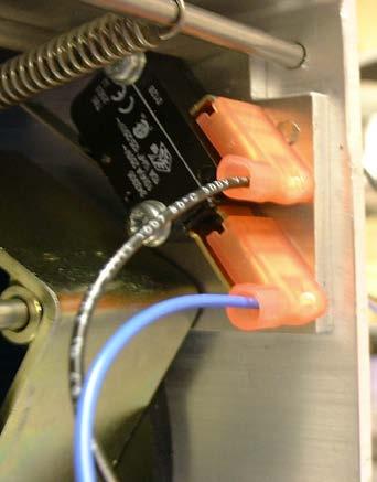
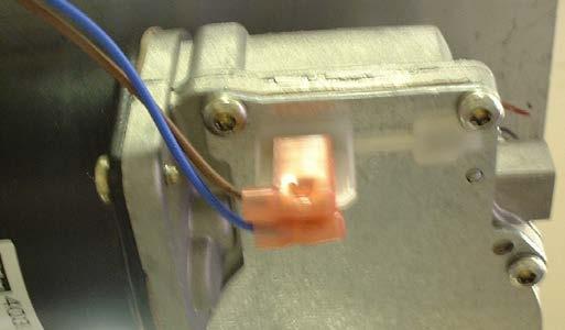
12 If the tape is wound in too far, the double thickness of the tape contains a magnet which operates a reed switch. This breaks the motor circuit and stops the motor instantly. There is also a lower limit switch to prevent the lifting tape to unwind too far, this is controlled by a metal lever which rests on the wound tape until it reduced sufficiently to operate the switch which stops the motor. This switch can be adjusted so that there is sufficient tape wound around the shaft to hold the hoist correctly. Also there is a slack tape switch which is operated should the hoist lower onto something and the tape goes slack. This again turns off the motor until the tape is tight again. 3.5 Emergency Stop On/Off Switch 1 Remove the covers as detailed in Disconnect one lead from the battery to isolate the supply 3 Unsolder the leads to the switch making a note of their positions 4 Press the sides of the switch locating lugs inwards to disengage from the side cover Refitting is the reverse procedure of the above 3.6 Emergency Lowering Switch 1 Remove the top cover as detailed in Disconnect one lead from the battery to isolate the supply 3 Disconnect the wires on the switch 4 Squeeze the switch locking arms in to allow the switch to pass through its holder Refitting is the reverse procedure of the above 4. Electrical Wiring See the attached schematic drawing 5. Load Testing All installations/hoists should be proof load tested to at least 100% of its maximum load along the entire track length to ensure that the installation is safe. To carry out this test, a weight of 200kg (440lbs) is attached to the sling support arms. Raise the weight to the up limit and lower to within 50mm (2 ) of the floor, traverse the hoist along the track to either end. If the hoist completes this test successfully a Hoist test certificate form should be completed. 6. Spare Parts 12
13 13
14 14
15 Wispa Lite Spare Parts ITEM PART No. QTY DESCRIPTION Chassis Tape Shaft Bush 15mm Internal Diameter Bush 20mm Internal Diameter Worm Shaft Pin 4mm diameter x 90.5mm long Push-On Fixing 4mm diameter Gear Wheel Spool Guide Disc - 20 Internal Diameter Spool Guide Disc 26 Internal Diameter Lanyard & Handle Bracket Governor Arm Pin Motor 15 MHWMES27 2 Battery - 12V, 2A Stop Block Arm 17 COM M5 Nylon Pillar 18 OH Micro Switch 19 COM Circlip 20mm diameter 20 COM Circlip 8mm diameter Main PCB Wheel Pin Governor Arm Pin Hanger Arm Left Hanger Arm Right Strap Retainer 27 0H Reed Switch (Part of loom) Membrane Panel LH Membrane Panel RH 30 COM Thrust Bearing Slack tape shaft 32 COM Spring 32A OH Governor Arm Spring Carry Handle 34 OH On / Off Switch 35 OH Emergency Lower Switch 36 COM Covered Push On Fixing 37 N/A 1 Hand Control Connector 38 OH Micro switch with lever CI 1 Hand Control 40 COM R Clip 15
16 ITEM PART No. QTY DESCRIPTION Lifting Tape 42 COM Push-On Fixing M4 43 COM Nylon Washer 44 COM Ball Spring Plunger 45 COM M6 Hex Head Screw x 55mm 46 COM M6 Nylok 47 COM Tape Securing Pin 48 OH Battery Cushion Pad self adhesive foam Micro switch Plate Cover Retaining Bar Battery Bracket Top Cover Bottom Cover LH Side Cover RH Side Cover 56 N/A 1 Charger Socket Part of loom 57 COM M6 Countersunk Head Screw x 12mm long 58 COM M5 Button Head Screw x 10mm long 59 COM M4 Switch adjust Screw x 12mm long 60 COM M6 Governor arm washer Washer 61 COM M3 Pozi Driv Button Head Screw x 14mm long 62 COM M3 Plain Washer 63 5 Cover screws 64 COM M4 Bolt x 18mm long 65 N/A N/A Not Available 66 COM M3 Reed switch screw x 12mm long 67 COM Reed switch plain washer Emergency Lowering Switch Bracket 69 COM M4 EL screws x 12mm long Not Shown CI 1 Charger Unit Not Shown BF 1 Charger Unit USA 110 volt 16
17 7. Appendix 17

18 OHWLP01 WIRING DIAGRAM Slack Tape Switch Top Limit Switch Battery Connections Low Limit Switch On / Off Switch PCB-Loom Connections Membrane Connections Charge Socket Emergency Lowering Motor Connections 18 D. MILNER
19 19


20 20
Moving and Handling. 200 and 300 Series Ceiling Mounted Hoist Range. Wispa
 Moving and Handling Wispa 200 and 300 Series Ceiling Mounted Hoist Range The complete Moving & Handling solution for the home, nursing home and hospital Chiltern Invadex the Complete Moving and Handling
Moving and Handling. Wispa. 200 and 300 Series Ceiling Mounted Hoist Range
 Moving and Handling www.chilterninvadex.co.uk Wispa 200 and 300 Series Ceiling Mounted Hoist Range The complete Moving & Handling solution for the home, nursing home and hospital Moving and Handling Wispa
Secure Sling Hooks with safety catches.
 Porter 500 The Porter-500 is a mobile Transfer Lift designed and developed in collaboration with Health Care Professionals. The sleek, strong built lift, included with a complete range of functional slings,
Moving and Handling Solutions
 Ceiling Track Hoist Wispa Moving and Handling Solutions Made in the UK Wispa Hoist Range Moving and handling solutions for home, leisure and caring environments Healthcare providers have been working towards
Guidelines for the Safe Use of Mobile Electric Patient Lifting Hoists
 Guidelines for the Safe Use of Mobile Electric Patient Lifting Hoists Responsible person: Tina Sore, Clinical Skills Lead Reviewed by: Tina Sore, Clinical Skills Lead and Anita Mobley, Manual Handling
Oxford /Hoyer. Professional Series. Presence Lift SERVICE MANUAL Rev B
 Oxford /Hoyer Presence Lift Professional Series SERVICE MANUAL CONTENTS Pages 3-4 Inspection Criteria of the Oxford/Hoyer Presence Page 5 Testing of the Oxford/Hoyer Presence Pages 6-13 Service and Maintenance
SONATA 150 ELS MOBILE PATIENT LIFTING HOIST USER MANUAL IMPORTANT:
 SONATA 150 ELS MOBILE PATIENT LIFTING HOIST USER MANUAL IMPORTANT: Do not use the SONATA 150 ELS PATIENT LIFTING HOIST Without having first read this manual. 30-32 James Street, Lidcombe, NSW 2141 Australia
Oxford /Hoyer. Professional Series. Adaptive Power Cradle SERVICE MANUAL Rev A
 Oxford /Hoyer Adaptive Power Cradle Professional Series SERVICE MANUAL CONTENTS Pages 3-4 Inspection Criteria of the Oxford/Hoyer APC Page 5 Testing of the Oxford/Hoyer APC Pages 6-11 Service and Maintenance
C300/P300. Technical Manual
 C300/P300 By Vancare Technical Manual Manufactured for: VANCARE, INC. 1515 1ST STREET, AURORA, NE 68818 T (800) 694-4525 F (402) 694-3994 info@vancare.com www.vancare.com P300/C300 Technical Manual REV
WISPA 100 Plus. User Guide. All 100 Plus models
 This user guide contains essential information in relation to safe use and troubleshooting and should be retained with the hoist for reference WISPA 100 Plus User Guide All 100 Plus models Unit 6C Thorpe
A205 Patient Lifter - Aluminium USER MANUAL
 A205 Patient Lifter - Aluminium USER MANUAL IMPORTANT: Do not use the ASPIRE A205 Lifter without having first read this manual. TABLE OF CONTENTS 1. Overview 3 2. Safety Precautions 4 3. Parts Glossary
1 TONNE FOLDING CRANE. 1 TONNE FOLDING CRANE MODEL No CFC100 PART No OPERATING & MAINTENANCE INSTRUCTIONS 1202
 1 TONNE FOLDING CRANE 1 TONNE FOLDING CRANE MODEL No CFC100 PART No 7611005 OPERATING & MAINTENANCE INSTRUCTIONS 1202 2 11 SPARE PARTS No Description Qty Part No No Description Qty Part No 1 Main Support
Yesterday s challenge Today s solution. User Manual. innova.uk.com
 Yesterday s challenge Today s solution User Manual innova.uk.com Contents 2 www.innova.uk.com Contents Contents 1. Purpose & Use 1.1 Introduction 4 1.2 Who are Innova? 5 1.3 Unpacking & preparation 6 1.4
Service Manual. Model L500 and L600 Smart Lift. WARNING: Cancer and Reproductive Harm - Form #1-144 Rev.
 Service Manual Model L500 and L600 Smart Lift WARNING: Cancer and Reproductive Harm - www.p65warnings.ca.gov. Form #1-144 Rev. 2/5/19 Table of Contents Parts Breakdown 3 Monthly Maintenance Checklist 5
Service Manual Model L1000 Smart Lift
 Service Manual Model L1000 Smart Lift Form #1-147 Rev. 10/1/13 Table of Contents Parts Breakdown 3 Monthly Maintenance Checklist 5 Smart Lift Operating Instructions 7 Scale Calibration 8 Advanced Smart
P-600. Technical Manual. Troubleshooting Repairs Replacements
 P-600 Technical Manual Troubleshooting Repairs Replacements Table of Contents P-600 Lift Symptoms and Problems Finding the Problem Before Getting Inside 3 Pneumatic Systems 4 Electrical Systems 5 Mechanical
Moving and Handling Solutions
 Ceiling Track Hoist Wispa 200 and 300 Hoist Range Moving and Handling Solutions 93/42/EEC Made in the UK Wispa Hoist Range Moving and handling solutions for home, leisure and caring environments Healthcare
Yesterday s challenge Today s solution. User Manual. innova.uk.com
 Yesterday s challenge Today s solution User Manual innova.uk.com Contents 2 www.innova.uk.com Contents Contents 1. Purpose & Use 1.1 Introduction 4 1.2 About the manufacturer 5 1.3 Unpacking & preparation
Likorall. LOAD TESTING 12 Mechanical lowering load test (242) Maximum load rail system... DOCUMENTATION 14 Instructions / Instruction guide...
 Maximum load rail system... DOCUMENTATION 14 Instructions / Instruction guide...") 6.1 Likorall 200, 240, 242, 243, 250 Periodic inspection 24-06-26 Lift type:... Prod No:... Version: Serial No:... Prod. Year:... Customer Reference: Contract No:... Name:... Address:... (Zip Code)...
6.1 Likorall 200, 240, 242, 243, 250 Periodic inspection 24-06-26 Lift type:... Prod No:... Version: Serial No:... Prod. Year:... Customer Reference: Contract No:... Name:... Address:... (Zip Code)...
A200S Patient Stander - Aluminium USER MANUAL
 A200S Patient Stander - Aluminium USER MANUAL IMPORTANT: Do not use the ASPIRE A200S Stander without having first read this manual. TABLE OF CONTENTS 1. Overview 3 2. Safety Precautions 4 3. Parts Glossary
atient lifters Assembly, Maintenance & Specifications Manual SUNRISE HML400 Hoyer Manual Patient Lift HPL400 Hoyer Power Patient Lift Sunrise Medical
 SUNRISE 800-556-5438 Oshkosh, WI 54901 2815 Oregon Street Continuing Care Group Sunrise Medical HML400 Hoyer Manual Patient Lift HPL400 Hoyer Power Patient Lift Assembly, Maintenance & Specifications Manual
INSTRUCTION MANUAL. Pacific Self-locking Beam Trolleys Pacific Adjustable Angle Clamps Pacific Top Girder Clamps
 INSTRUCTION MANUAL Pacific Self-locking Beam Trolleys Pacific Adjustable Angle Clamps Pacific Top Girder Clamps IMPORTANT Please read this instruction manual before using these products. This manual contains
 Minivator 1000 series 000137 52049 issue 0200 Installation Manual Contents First check that all the required components are available: 4 Special installation tools 4 To assemble the track 5 Fit the charge
SGA-440 by Prism Medical
 SGA-440 by Prism Medical Introduction... 2 Overview... 2 Components of the Sit to Stand Lift... 3 Component List... 4 Specifications... 5 Cautions... 6 Assembly Instruction... 7 Operation Charging......12
Voyager Portable. Oxford. Key features. High performance portable lifting solutions
 Oxford Voyager Portable High performance portable lifting solutions Voyager Portable The Voyager Portable hoist, Easytrack and Easytrack FS systems combine to form a unique portable overhead lifting solution
WARNING. When installed in accordance with these instructions, the front protection bar does not affect operation of the SRS airbag.
 Part Number: 36030 Product Description: BULL BAR WINCH TYPE Suited to vehicle/s: CHEVROLET C/K 500-3500 988-998 YEAR MODEL RANGE AND Warn 9,500-5,000lb WINCHES WARNING REGARDING VEHICLES EQUIPPED WITH
WARNING. When installed in accordance with these instructions, the front protection bar does not affect operation of the SRS airbag.
 Part Number: 343870 F/Kit 17557 Product Deluxe Combination Winch and Non Winch Bull Bar Description: Suited to Nissan XTERRA 05ON USA Only vehicle/s: WARNING REGARDING VEHICLES EQUIPPED WITH SRS AIRBAG;
Moving and Handling. Specify. The technical specifications manual for the Polaris Medical Range of Ceiling Track Lifts.
 C ei lin g Tr ac k Moving and Handling Specify The specifications manual for the Polaris Medical Range of Ceiling Track Lifts H oi st s Ceiling Track Hoist Range Contents This work is the property of Chiltern
Numatic International Spare Parts Model No: Numatic International Spare Parts Model No: NB: FOR WIRING SEE DRAWING: DRW-7279
 TTB 0 BASE ASSEMBLY EXPLODED DRAWING NB: FOR WIRING SEE DRAWING: DRW- 0 0 0 0 0 0 0 0 0 0 0 DRAWING: DRW-0 ISS:A0 /0/0 0 TTB 0 BASE ASSEMBLY EXPLODED DRAWING TTB 0 CHASSIS WELDED ASSEMBLY 0 TTB 0 HANDLE
Wallace Tri-Adjustable Gantry Cranes Square Tube Assembly Instructions
 Wallace Tri-Adjustable Gantry Cranes Square Tube Assembly Instructions For any additional information, Please call 1- S 1. Read and understand instructions before using this gantry. 2. Inspect gantry thoroughly
SERVICE MANUAL. Koala
 SERVICE MANUAL Koala US How to contact Permobil Permobil Inc. USA 6961 Eastgate Blvd. Lebanon, TN 37090 USA Phone: 800-736-0925 Fax: 800-231-3256 Email: info@permobilusa.com Head Office of the Permobil
GMR-S and GMR40-S Disc Brake Caliper - Spring Applied, Air Released
 (GMR) 9 (GMR) ø GMR-S and GMR-S Disc Brake Caliper - Spring Applied, Air Released DB Nominal dimensions given. For specific dimensions please contact Twiflex Limited. For GMR Mk caliper details see DB
Prism A-205. Owner s Manual. Aluminium Mobile Hoist. Use and Care Trouble Shooting Warranty Information. Introduction Overview...
 Prism A-205 Aluminium Mobile Hoist Introduction... 2 Overview... 2 Components of the Mobile hoist... 3 Component List... 4 Specifications... 5 Cautions... 6 Assembly Instruction... 7 Operation Charging......13
SERVICE GUIDE For WARN PULLZALL 24Vdc P/N &
 SERVICE GUIDE For WARN PULLZALL 24Vdc P/N 885005 & 885006 REPAIR / REPLACEMENT INSTRUCTIONS TROUBLE SHOOTING GUIDE 987606A1.doc Page 1 of 46 WARNING This guide identifies potential hazards and has important
USER MANUAL. Item: #13246 Stand-Aid Lift. Drive Medical Design and Manufacturing
 USER MANUAL Item: #13246 Stand-Aid Lift IMPORTANT SAFEGUARDS Your lift is for transferring patients only. Do not use the lift for any other purpose. Stand-Aid Lift is intended to be used for persons within
STRUT SPRING COMPRESSOR
 OWNER S MANUAL PRODUCT CODE: 1221T STRUT SPRING COMPRESSOR Capacity Stroke Spring Coil Spring Spring Coil Net Weight (Maximum) Thickness Length Diameter 1,000kg 330mm 10-18mm 210-570mm 100-158mm 36kg Made
W BW GW. Workshop manual. Mechanical suspensions BPW, series ECO Cargo W / BW / GW. BPW-WH-W-BW-GW e
 W BW GW Workshop manual Mechanical suspensions BPW, series ECO Cargo W / BW / GW BPW-WH-W-BW-GW 35251401e Page 2 BPW-WH-W-BW-GW 35251401e BPW-WH-W-BW-GW 35251401e Page 3 Contents 1. Product identification...
CHAPTER 10 : STERLING STAR PLUS
 CHAPTER 10 : STERLING STAR PLUS Sterling Star range is a transportable rear wheel drive, three or four wheel electric powered Scoota with pneumatic tyres, rake adjustable tiller, upholstered seat with
Pallas/150. Stand-aid lifter. User instruction. Important - information. This user instruction must be read before the Pallas 150 is used.
 Pallas/150 Stand-aid lifter User instruction Important - information This user instruction must be read before the Pallas 150 is used. This user instruction is intended for technicians, installers, therapists
Before equipment use, please read this operation manual carefully. Serial Number: Date Purchased:
 Pushed & Geared Trolleys OPERATION MANUAL This operation manual is intended as an instruction manual for trained personnel who are in charge of installation, maintenance, repair etc. Before equipment use,
AURELIA LTD A59 EXCAVATOR 360 ABOVE 10 TONNES INC LIFTING TECHNICAL TEST THEORY CPCS Issue 09-Jul-2012
 Name THREE ways that a plant operator can contribute in ensuring repeat business with the client or principal contractor. What is the meaning of this hand signal (being demonstrated by the tester)? What
SPIRIT - FRAME ASSEMBLY
 Titel - 1 - Titel - 2 - Table Of Contents QUICKIE SPIRIT... 4 FRAME... 4 SPIRIT - FRAME ASSEMBLY... 4 SEATING... 6 SPIRIT - STD SEAT AND BACKREST... 6 SPIRIT - UNISUN BACKREST- DISCONTINUED... 8 HANGERS
PERFORM THE FOLLOWING SAFETY CHECK DAILY:
 FITNESS Introduction We at Vectra Fitness appreciate your selection of our product for your fitness program, and invite your questions and comments. We're sure that you ll be pleased with your new Vectra
USER MANUAL. Item: #13246 Stand-Aid Lift. Drive Medical Design and Manufacturing Push Handle. Base Width Adjustment Handle.
 USER MANUAL Item: #13246 Stand-Aid Lift Push Handle Base Width Adjustment Handle Mast Sling Attachment Hook Adjustable Knee Pad Front Caster W/Brake Foot Plate Front Caster W/O Brake Rev1.06.11.14 IMPORTANT
Standard Valves Series Globe Valves Series Angle Valves Series Way-Valves
 Installation, Operation, Maintenance Instructions Standard Valves Series 035 000 Globe Valves Series 031 000 Angle Valves Series 033 000 3-Way-Valves 1 GENERAL INFORMATION These instructions are designed
Convertible - Rated 3 4-Ton /2-Ton Nylon Strap Hoists Refer to any questions about the use, application, repair or testing of this hoist to:
 Operating and Servicing Instructions for Convertible - Rated 3 4-Ton - 1 1 /2-Ton Nylon Strap Hoists Refer to any questions about the use, application, repair or testing of this hoist to: Hubbell / Chance
Poollift Neptune with Transporter
 Poollift Neptune with Transporter Operating and Product Care Instructions Doc.:065 Rev.: 0 Datum: 26/11/2012 Thank you for purchasing Nibotechncis equipment. Your POOL LIFT is one of a series of quality
The EFL 2000/1 & 2 User Guide Test Sieve Shaker. Contents
 The EFL 2000/1 & 2 User Guide Test Sieve Shaker ISSUE 04-02 Contents Description Page 1 Setting Up: 2-8 Unpacking 2 Assembly 3 Clamping Assembly 4 Electrical Connections 5 Sieve Stacking 6 8 Operating
FX140 & FX140R Skidding Winch Parts Manual
 EMB Manufacturing Inc. 4144 Boomer Line St. Clements, On N0B 2M0 Canada Ph: (519) 699-9283 Fax: (519) 699-4146 www.wallensteinequipment.com FX140 & FX140R Skidding Winch Parts Manual S/N 514094 & After
ARB 4x4 ACCESSORIES Corporate Head Office
 Part Number: 34500 Product Description: Suited to vehicle/s: COMBAR DODGE RAM 003-05 500 00-05 ADD BRACKET KIT# 35500 500/3500 003-05 ADD BRACKET KIT# 35500 WARNING REGARDING VEHICLES EQUIPPED WITH SRS
500kg HYDRAULIC TABLE LIFT
 Product Code: 6007T OWNER S MANUAL PRODUCT CODE: 6007T 500kg HYDRAULIC TABLE LIFT Working Load Limit 500kg Maximum Height 1575mm Minimum Height 440mm Table Dimensions 1010x520mm Wheel Diameter 150mm Made
Instruction Booklet INSTRUCTION MANUAL
 Instruction Booklet INSTRUCTION MANUAL INTRODUCTION Introduction These instructions must be read by any person intending to use or service the machine. Purpose of use This equipment is expressly designed
WARNING. When installed in accordance with these instructions, the front protection bar does not affect operation of the SRS airbag.
 Part Number: 346400 F/Kit 6774 Product ARB WINCH BULL BAR Description: Suited to NISSAN TITAN YEAR MODELS 04 to 07 vehicle/s: WARNING REGARDING VEHICLES EQUIPPED WITH SRS AIRBAG: When installed in accordance
SERVICE GUIDE For WARN PULLZALL 120Vac P/N &
 SERVICE GUIDE For WARN PULLZALL 120Vac P/N 885000 & 885001 REPAIR / REPLACEMENT INSTRUCTIONS TROUBLE SHOOTING GUIDE 987604A2.doc Page 1 of 48 WARNING This guide identifies potential hazards and has important
Service Tools. Service and Repair Manual Model 900/950/990 ITEM PART NO. DESCRIPTION ITEM PART NO. DESCRIPTION ITEM PART NO.
 12 1 3 2 4 5 8 10 6 7 9 11 14 24 12 13 17 22 29 18 23 25 19 26 15 20 27 21 16 22 33 37 38 32 31 36 30 34 35 40 41 42 43 ITEM PART NO. DESCRIPTION 1 9170 0231 30 LONG ALLEN KEY 2 9170 0737 20 3/32 PIN PUNCH
WARNING. Part Number: Description: Suited to TOYOTA FJ CRUISER ALSO, NOTE THE FOLLOWING:
 Part Number: 5620010 Product ARB REAR BAR Description: Suited to TOYOTA FJ CRUISER vehicle/s: ALSO, NOTE THE FOLLOWING: WARNING This product must be installed exactly as per these instructions using only
Uniclass L7716 EPIC Q233. Oxford. CI/SfB (66.2) X (U35) Voyager Ceiling Hoist Range. Redefining patient handling
 X (U35) Voyager Ceiling Hoist Range. Redefining patient handling") Oxford Uniclass L7716 CI/SfB EPIC Q233 (66.2) X (U35) Voyager Ceiling Hoist Range Redefining patient handling Voyager 420, 550 & 800 Whether its for the institutional or homecare environment, the Voyager
Oxford Uniclass L7716 CI/SfB EPIC Q233 (66.2) X (U35) Voyager Ceiling Hoist Range Redefining patient handling Voyager 420, 550 & 800 Whether its for the institutional or homecare environment, the Voyager
Free Standing Track. Owner s Manual. Use and Care Trouble Shooting
 Free Standing Track Owner s Manual Use and Care Trouble Shooting VANCARE, INC. 1515 1ST STREET, AURORA, NE 68818 T (800) 694-4525 F (402) 694-3994 info@vancare.com www.vancare.com Table of Contents Free
SERVICE MANUAL. Chairman HD3
 SERVICE MANUAL Chairman HD3 US How to contact Permobil Head Office of the Permobil group Produced and published by Permobil AB, Sweden Edition no.3, 2009-08 Article no.: 201161-US-0 Contents Contents
Electric Diesel Pump EDP/12, EDP/24
 INSTRUCTION MANUAL Electric Diesel Pump EDP/1, EDP/4 S1940, Rev C Congratulations on purchase of this World Class Electric Diesel Pump! Portable Diesel transfer pumps designed for everyday use in Agricultural,
Sub Section Title Page No.
 Sub Section Title Page No. 1 Introduction 3 2 Routine Maintenance 3 3 Disassembly 4 3.1 Disassembly of Double Crank Design 4 3.2 Disassembly of Scotch Yoke Design 5 3.3 Disassembly of Actuator Cylinder
Safelift Overhead Runway Beams & Rolling Beam Cranes
 Operation & Maintenance Instructions Instructions for Safe Use Safelift Overhead Runway Beams & Rolling Beam Cranes Certification Safelift overhead runway beams and rolling beam cranes are lifting appliances
Electric Hoist. LE 250 (kg) D 230 V 60 m. 6 m. 60 m. 6 m
 D 230 V 60 m. 6 m. 60 m. 6 m") Electric Hoist LE 250 (kg) D 230 V 60 m 6 m 6 m 60 m 1 TECHNICAL DATA Model 2 LE 250 D 230 V 60 mtr Voltage 230V, 50Hz Current (A) 5.7 Input power (W) 1300 Rated load (kg) 250 Lifting height (m) 60 *Rated
Electric Hoist LE 250 (kg) D 230 V 60 m 6 m 6 m 60 m 1 TECHNICAL DATA Model 2 LE 250 D 230 V 60 mtr Voltage 230V, 50Hz Current (A) 5.7 Input power (W) 1300 Rated load (kg) 250 Lifting height (m) 60 *Rated
Maxi Twin II. Parts List. ...with people in mind. 05.KT.02_8EN 01/2018 XXX.XXX Rev A 12/2014
 Maxi Twin II Parts List 05.KT.0_8EN 01/018 XXX.XXX Rev A 1/014...with people in mind General information Note. All article numbers starting with 85 indicates that more than one detail is included in the
VANDERLIFT II MAINTENANCE MANUAL. Models: B450, B450 w/scale, B600 and B600 w/scale
 VANDERLIFT II MAINTENANCE MANUAL Models: B450, B450 w/scale, B600 and B600 w/scale Table of Contents Part Diagrams & Lists Vanderlift II B450...2-3 Vanderlift II SB450 w/built in scale...4-5 Vanderlift
Service manual. English. F5 Corpus
 Service manual English F5 Corpus Introduction The Service Manual is intended for technical personnel who maintain and repair power wheelchairs. It is important that anyone who performs maintenance and
WARNING. Electric Recovery Winch. General Safety Precautions
 1 Electric Recovery Winch Thanks for purchasing a WINCH. This manual covers operation and maintenance of the winch. All information in this publication is based on the latest production information available
SERVICE MANUAL US. Permobil M300/M400. Power Wheelchair
 SERVICE MANUAL US Permobil M300/M400 Power Wheelchair How to contact Permobil Head Office of the Permobil group Produced and published by Permobil AB, Sweden Version 2, 2011-06 Article no.: 205261-US-0
SERVICE MANUAL. Chairman. Playman/Robo
 SERVICE MANUAL Chairman Playman/Robo US How to contact Permobil Permobil Inc. USA 6961 Eastgate Blvd. Lebanon, TN 37090 USA Phone: 800-736-0925 Fax: 800-231-3256 Email: info@permobilusa.com Head Office
Instruction manual. RP800 - HYDRAULIC actuator, load 150Kg. RP815 - LINAK actuator, load 150Kg
 HYDRAULIC patient lift RP800 - HYDRAULIC actuator, load 150Kg MA RP800_805_806_ 807_810_811_815 02 A_12-2010 Electric patient lifts RP805 - LINAK actuator, load 150Kg RP806 - HIWIN actuator, load 150Kg
3 Axles and brakes. 3.1 Function and construction of the axles Construction Function
 3 Axles and brakes 3.1 Function and construction of the axles 3.1.1 Function Each wheel has an independent suspension system in the axle body (1), so that individual wheel suspension is provided. The swinging
Z TECHNICAL INSTRUCTIONS
 ÍNDICE: Z40 2.0 TECHNICAL INSTRUCTIONS 1.- Error list 2.- Replace the control board 3.- Opening the machine 4.- Replace the power board 5.- Dismantling motor and gear box 6.- Assembly of gear box 7.- Pushing
SECTION H STEERING. Section Description Page No. H.1 GENERAL DESCRIPTION 3 H.2 STEERING WHEEL 3 H.3 INNER COLUMN 5 H.
 SECTION H STEERING Section Description Page No. H.1 GENERAL DESCRIPTION 3 H.2 STEERING WHEEL 3 H.3 INNER COLUMN 5 H.4 OUTER COLUMN 5 H.5 STEERING UNIT LOCK STOPS 6 H.6 STEERING UNIT 6 H.7 STEERING ARMS
215E. Operator and Parts Manual MM158
 5E Operator and Parts Manual MM58 This manual is furnished with each new TENNANT Model 5E This manual consists of Specifications; Operation; Maintenance; Appendix; the How To Use This Manual; Low Dump
ON-THE-VEHICLE BRAKE LATHE
 800 ON-THE-VEHICLE BRAKE LATHE Parts Identification READ these instructions before placing unit in service. KEEP these and other materials delivered with the unit in a binder near the machine for ease
Graduate 150 Scholar 175 Master 200
 Instruction Manual for Graduate 150 Scholar 175 Master 200 Contents Unihoist Ltd Electric and Hydraulic illustrations..... 2-3 Introduction.. 4 Assembly and commissioning instructions... 5-6 Safety precautions....
SERVICE MANUAL. Chairman
 SERVICE MANUAL Chairman US How to contact Permobil Permobil Inc. USA 6961 Eastgate Blvd. Lebanon, TN 37090 USA Phone: 800-736-0925 Fax: 800-231-3256 Email: info@permobilusa.com Head Office of the Permobil
USER S MANUAL CAUTION. Visit our website at. new products, prizes, fitness tips, and much more!
 Patent Pending Model No. 831.159730 Serial No. The serial number is found in the location shown below. Write the serial number in the space above. USER S MANUAL Serial Number Decal SEARS, ROEBUCK AND CO.
The Future of Homecare Lifting is Here!
 HYDRAULIC OR BATTERY OPERATED MODEL:400H / 400EL / 400LK The Future of Homecare Lifting is Here! Thank you for choosing the BestLift 400 To better serve you, please record the following information: Dealer
OWNERS GUIDE 12V / 24V DC ELECTRIC WINCH. 12,000lb (6124kg) TWO SPEED VERY IMPORTANT
 TWO SPEED VERY IMPORTANT") OWNERS GUIDE 12V / 24V DC ELECTRIC WINCH. 12,000lb (6124kg) TWO SPEED VERY IMPORTANT IT IS ESSENTIAL THAT YOU READ AND UNDERSTAND THIS GUIDE BEFORE INSTALLING AND OPERATING YOUR WINCH WINCHMAX UK WWW.WINCHMAX.CO.UK
OWNERS GUIDE 12V / 24V DC ELECTRIC WINCH. 12,000lb (6124kg) TWO SPEED VERY IMPORTANT IT IS ESSENTIAL THAT YOU READ AND UNDERSTAND THIS GUIDE BEFORE INSTALLING AND OPERATING YOUR WINCH WINCHMAX UK WWW.WINCHMAX.CO.UK
Your G3 buggy is fitted with three switches on the front part of the body:
 CONTENTS Buggy operation... 3 General Maintenance... 5 Technical Maintenance... 6 Front wheel bearing replacement... 6 Rear wheel bearing replacement... 7 Chain replacement... 8 Chain Adjustment... 9 Brake
P44 Stepper. User Manual
 P44 Stepper User Manual Table of Contents Introduction 1 Safety Warning 2 Overview of Parts 2 Attaching to Chair 3 Manoeuvring Around 4 Setting Pedal Stops 4 Getting On 5 Setting the Resistance (models
Encore S28/L28/S33/L33/S38/L38. Section II. Parts and Service Manual (79049B)
") Encore S8/L8/S/L/S8/L8 Section II Parts and Service Manual (9049B) CLARKE TECHNOLOGY Operator's Manual - Encore S8/L8/S/L/S8/L8 - - HOW TO CORRECT PROBLEMS IN THE MACHINE PROBLEM CAUSE ACTION The machine
Encore S8/L8/S/L/S8/L8 Section II Parts and Service Manual (9049B) CLARKE TECHNOLOGY Operator's Manual - Encore S8/L8/S/L/S8/L8 - - HOW TO CORRECT PROBLEMS IN THE MACHINE PROBLEM CAUSE ACTION The machine
DB4604 GMR-SD and GMR40-SD Disc Brake Caliper - Spring Applied, Air Released
 DB464 GMR-SD and GMR4-SD Disc Brake Caliper - Spring Applied, Air Released Nominal dimensions given. For specific dimensions please contact Twiflex Limited. For GMR Mk 2 caliper details see DB 364 Air
PIL0478 ISSUE 01/ 07/16
 ISSUE 01/ 07/16 PIL0478 ZAFIR G9 CEILING FITTING PIL0478 ISSUE 01/ 07/16 PART C PART E PART 21 SELV 1 1.B 1 3.1 3.3 3.4 3.5 3.6, 3.8 3.10 3.12 3.14 3.16 3.17 3.18 3.19 3.19 ATTENTION! THE TABLE BELOW
HEAVY DUTY CRANE HDC RANGE OPERATING G & MAINTENANCE INSTRUCTIONS
 HEAVY DUTY CRANE HDC RANGE OPERATING G & MAINTENANCE INSTRUCTIONS 0599 SPECIFICATIONS cont... No. Description Part No. No. Description Part No. MAXIMUM SAFE WORKING LOADS (kg) HDC50 HDC100 HDC150 HDC200
ALTO LIFT 200 Mobile Patient Lifting Hoist Instruction & Safety Manual
 ALTO LIFT 200 Mobile Patient Lifting Hoist Instruction & Safety Manual Please read this manual before operation, for The enabling power of applied knowledge ALTO LIFT 200, Instruction & Safety Manual Contents
 AUTOGARD SERIES 820 TORQUE LIMITER Installation and Maintenance Manual DB0009 Issue 11 21 Feb 2017 British Autogard Ltd 2 Wilkinson Rd., Love Lane Industrial Estate, Cirencester, Glos., GL7 1YT UK Tel.
Fitting Instructions: Street Triple from VIN and Street Triple R from VIN A
 English Fitting Instructions: Street Triple from VIN 560477 and Street Triple R from VIN 560477 A9808113 Thank you for choosing this Triumph genuine accessory kit. This accessory kit is the product of
WH/WK JEEP GRAND CHEROKEE 2005 ON WARNING
 Part Number: 3450130 F/KIT: 6172092 Product Description: Suited to vehicle/s: COMBINATION BULL BAR WH/WK JEEP GRAND CHEROKEE 2005 ON WARNING REGARDING VEHICLES EQUIPPED WITH SRS AIRBAG; When installed
RIGID PENDANT. Phoenix Pipeline Products Limited. Installation, Operation and Maintenance Manual
 RIGID PENDANT Phoenix Pipeline Products Limited. Unit 8, McKenzie Industrial Park, Tel No.: 44 (0) 161 428 7200 Bird Hall Lane, Fax No.: 44 (0) 161 428 7010 Stockport, Email: info@p3-phoenix.com U.K.,
Technical Test Theory Excavator 360 above 10 tonnes A59
 1 If the operator has loaded the machine onto a transporter/trailer on behalf of a driver, what checks must be carried out before they leave the cab? 2 Why should different soils be segregated during excavating?
Disassembly and Reassembly Manual
 AS No.ER2-0908-MC-00 ER2 Series Electric Chain Hoist (125kg to 5t) Disassembly and Reassembly Manual Safety precaution This Disassembly and Reassembly Manual includes contents to prevent injury to any
WARNING. ARB 4x4 ACCESSORIES. Corporate Head Office Garden St Tel: +61 (3) Kilsyth, Victoria Fax: +61 (3) AUSTRALIA 3137
 Kilsyth, Victoria Fax: +61 (3) AUSTRALIA 3137") Part Numbers: Suited to vehicle/s: 3212400 - ARB BULL BAR NON-FLARED 3212410 - ARB BULL BAR FLARED 3412400 - ARB WINCH BAR NON-FLARED* 3412408 - ARB WINCH BAR NON-FLARED (EXPORT ONLY)* 3412410 - ARB WINCH
Part Numbers: Suited to vehicle/s: 3212400 - ARB BULL BAR NON-FLARED 3212410 - ARB BULL BAR FLARED 3412400 - ARB WINCH BAR NON-FLARED* 3412408 - ARB WINCH BAR NON-FLARED (EXPORT ONLY)* 3412410 - ARB WINCH
PAPER SHREDDER S16 PAPER SHREDDER S16 ILLUSTRATED PARTS LIST AND SERVICE INSTRUCTIONS
 PAPER SHREDDER S16 PAPER SHREDDER S16 ILLUSTRATED PARTS LIST AND ISSUE 2 08/08/2002 PAPER SHREDDER INDEX S16 CONTENTS HEADING SECTION PREFACE AND INDEX INDEX ILLUSTRATED PARTS LIST 1 INSTALLATION 2 2 MODEL
MAINTENANCE AND TESTING OF PORTABLE ELECTRICAL EQUIPMENT, RCDS AND TOOLS CS-OHS-33
 CS ENERGY OPERATIONS PROCEDURE FOR MAINTENANCE AND TESTING OF PORTABLE ELECTRICAL EQUIPMENT, RCDS AND TOOLS CS-OHS-33 Responsible Officer: Electrical Services Engineering Manager Responsible Manager: Group
English. Fitting Instructions: Sprint GT 1050 A and A of 12
 English Fitting Instructions: Sprint GT 050 A950855 and A950856 Thank you for choosing this Triumph genuine accessory kit. This accessory kit is the product of Triumph's use of proven engineering, exhaustive
SERVICE MANUAL. Permobil C350. Power Wheelchair
 SERVICE MANUAL US Permobil C350 Power Wheelchair Contents Contents Introduction... 5 Rating plates... 6 Covers... 8 Batteries... 10 Rear wheels... 12 Support wheels... 14 Front wheels... 16 Wheel fork...
SERVICE MANUAL OF SERVOMOTORS HD/HR RANGE
 SERVICE MANUAL HD/HR RANGE OF SERVOMOTORS ISSUE 2 WARNING Servomotors contain magnetic material which will attract metal particles. Care should be taken when dismantling motors to avoid this. All D.C.
OPERATION MANUAL Electric Wire Wrapper TDWW501B
 OPERATION MANUAL Electric Wire Wrapper TDWW501B 4270 Airborn Drive Addison, Texas 75001 USA t. 972.248.1999 f. 972.248.1991 info@startinternational.com www.startinternational.com INTRODUCTION Thank you