Feed Bin Installation and Operation Manual 6, 7, 9, and 12 Diameter Feed Bins
|
|
|
- Joseph Lane
- 6 years ago
- Views:
Transcription


1 Feed Bin Installation and Operation Manual 6, 7, 9, and 12 Diameter Feed Bins
2 Table of Contents Hog Slat General Page... 3 Support Information... 3 Hardware Identification... 3 Safety Recognize Safety Information... 4 Warning Label... 4 General Safety Statement... 4 Hazards... 6 Foundation Foot Tank Foot Tank Foot Tank Foot Tank Alternate Anchors Sidewall Sheet Gauge Charts Sidewall Sheet Assembly Top Ring Middle Rings Bottom Rings Roof Panel Assembly Hopper Assembly Leg Assembly Brace Assembly Cross Brace Assembly Hopper Brace Assembly Lid Assembly Ladder Assembly Ladder Stand Off Vertical Ladder Assembly Roof Ladder Assembly Ladder Handrail Assembly Safety Cage Assembly Pnuematic Fill Assembly Erecting the Feed Bin Grounding Ladder Matrix Component Listing Foot Tank Foot Tank Foot Tank Foot Tank Lid Assembly Tank Specification Hog Slat Limited Warranty Company Info
. Failure to follow specified instructions may cause damage to equipment and/or personal injury or death.")
 when working with the equipment.")

3 Hog Slat General Page General Installation Notes: Installation of this equipment and related OEM equipment should be in accordance with these instructions, OEM s installation instructions and local codes (if applicable). Failure to follow specified instructions may cause damage to equipment and/or personal injury or death. Take special note of any Warnings or Safety Decals on the equipment and in manuals. Always wear protective clothing and any applicable Personal Protective Equipment (Safety Glasses and/or Ear Plugs) when working with the equipment. Discarded materials, equipment and boxes should be recycled in accordance with local and national codes. Support Information Hog Slat Feed Bins are designed for grains and/or free flowing materials. Using this equipment for any other purpose or in a way not within the operating recommendations specified in this Manual will void the Warranty and may cause injury or death. Do NOT place feed bins in direct air flow of exhaust fans. Identification of Hardware: WARNING! No hardware substitutions are permitted unless noted. HS722 Serrated Flange Nut HS714 5/16 x 3/4 Truss Head Bin Bolt HS712 5/16 x 1 Hex Head Bin Bolt Grade 8.2 Markings 3
4 Safety Warning Labels Warning Decals have been placed on the equipment to warn of potentially dangerous situations. Care should be taken to keep this information intact and easy to read at all times. Replace missing or damaged safety signs. Safety Alert Symbol This is a safety alert symbol. When you see this symbol on your equipment, be alert to the potential for personal injury. Hog Slat equipment is designed to be installed and operated as safely as possible...however, hazards do exist. Important Information Symbol This is an Information alert symbol. When you see this symbol throughout this installation manual, be sure to read the information provided. Safety decals should be read and understood thoroughly by individuals within the local area of the Feed System. Should a decal be missing or damaged, please contact Hog Slat Inc. for a free replacement: Hog Slat Inc. 206 Fayetteville St. Newton Grove, NC Toll Free: Local: DANGER! It is a matter of extreme SAFETY importance that your bins are NOT placed where feed trucks, augers or other equipment may accidentally come in contact with electric power lines, control boxes or other electrical hazards which may result in serious injury or death! Contact your power company before construction for a review of proper line clearance. This could save you the expense of moving facilities later. 4


 when Lid is in")
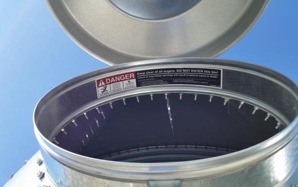
5 This safety decal should be represented and visible on the inside of the ladder rail at eye-level. This safety decal should be represented and visible on the inside of the Peak Ring (Fill-Hole) when Lid is in the open position. 5


6 DANGER! There are Suffocation Hazards in Flowing Grain and Feed! Never enter a bin of flowing feed, grain, or other material. Failure to follow these instructions will result in death or serious injury From the time the auger starts, you have 2-3 seconds to react. In 4-5 seconds, you are trapped. After 22 seconds, you are completely covered. 6
7 Foundation 6 Diameter Feed Bins # of Rings Slab Thickness (T) Concrete Volume Wire Mesh Area Qty of Legs Square " [279 mm] 2.2 Cu. Yards [1.68 Cu. Meters] 60 Sq. Ft. [5.57 Sq. Meters] 4 Round " [279 mm] 1.7 Cu. Yards [1.31 Cu. Meters] 55 Sq. Ft. [5.11 Sq. Meters] 4 Square Foundation Round Foundation 6 Maximum above Grade 6 Maximum above Grade 1. Foundation recommendations are based on 3500 lbs / ft² allowable soil bearing capacity. 2. Foundation recommendations are based on a minimum compressive strength of 3000 PSI at 28 days. 3. The foundation site must be well drained and free of vegetation and debris. 4. The foundation should be level within 1/4" overall and within +/-1/8 in any 10 foot length along the anchor bolt circle. 5. Material estimates do not include allowance for shrinkage and waste. 6. These layouts are recommendations for Hog Slat tanks only. Consult Hog Slat engineering for special tank foundations. 7
8 7 Diameter Feed Bins # of Rings Slab Thickness (T) Concrete Volume Wire Mesh Area Qty of Legs Square " [330 mm] 3.3 Cu. Yards [2.52 Cu. Meters] 80 Sq. Ft. [7.43 Sq. Meters] 4 Round " [330 mm] 2.6 Cu. Yards [1.91 Cu. Meters] 65 Sq. Ft. [6.04 Sq. Meters] 4 Square Foundation Round Foundation 6 Maximum above Grade 6 Maximum above Grade 1. Foundation recommendations are based on 3500 lbs / ft² allowable soil bearing capacity. 2. Foundation recommendations are based on a minimum compressive strength of 3000 PSI at 28 days. 3. The foundation site must be well drained and free of vegetation and debris. 4. The foundation should be level within 1/4" overall and within +/-1/8 in any 10 foot length along the anchor bolt circle. 5. Material estimates do not include allowance for shrinkage and waste. 6. These layouts are recommendations for Hog Slat tanks only. Consult Hog Slat engineering for special tank foundations. 8
9 9 Diameter Feed Bins # of Rings Slab Thickness (T) Concrete Volume Wire Mesh Area Qty of Legs Square " [330 mm] 4.9 Cu. Yards [4.85 Cu. Meters] 125 Sq. Ft. [11.61 Sq. Meters] 6 Round " [330 mm] 3.8 Cu. Yards [2.91 Cu. Meters] 100 Sq. Ft. [9.29 Sq. Meters] 6 Square Foundation Round Foundation 6 maximum above Grade 6 maximum above Grade 1. Foundation recommendations are based on 3500 lbs / ft² allowable soil bearing capacity. 2. Foundation recommendations are based on a minimum compressive strength of 3000 PSI at 28 days. 3. The foundation site must be well drained and free of vegetation and debris. 4. The foundation should be level within 1/4" overall and within +/-1/8 in any 10 foot length along the anchor bolt circle. 5. Material estimates do not include allowance for shrinkage and waste. 6. These layouts are recommendations for Hog Slat tanks only. Consult Hog Slat engineering for special tank foundations. 9
10 12 Diameter Feed Bins # of Rings Slab Thickness (T) Concrete Volume Wire Mesh Area Qty of Legs Square " [381 mm] 9.1 Cu. Yards [6.93 Cu. Meters] 196 Sq. Ft. [18.21 Sq. Meters] 8 Square 6 16" [406 mm] 9.7 Cu. Yards [7.40 Cu. Meters] 196 Sq. Ft. [18.21 Sq. Meters] 8 Round " [381 mm] 7.1 Cu. Yards [5.45 Cu. Meters] 155 Sq. Ft. [14.40 Sq. Meters] 8 Round 6 16" [406 mm] 7.6 Cu. Yards [5.81 Cu. Meters] 155 Sq. Ft. [14.40 Sq. Meters] 8 Square Foundation Round Foundation 6 maximum above Grade 6 maximum above Grade 1. Foundation recommendations are based on 3500 lbs / ft² allowable soil bearing capacity. 2. Foundation recommendations are based on a minimum compressive strength of 3000 PSI at 28 days. 3. The foundation site must be well drained and free of vegetation and debris. 4. The foundation should be level within 1/4" overall and within +/-1/8 in any 10 foot length along the anchor bolt circle. 5. Material estimates do not include allowance for shrinkage and waste. 6. These layouts are recommendations for Hog Slat tanks only. Consult Hog Slat engineering for special tank foundations. 10
11 Anchor bolt 5/8" x 8" (203 mm) bolt with an 1/8" thick x 1-3/4" O.D. washer on head. 11
12 Side Wall Sheet Gauge Chart Tank Gauge 6' - 60 Hopper BFT 6'-1 Ring 20 BFT 6'-2 Ring BFT 6'-3 Ring BFT 6'-4 Ring ' - 67 Hopper BFT 7'-1 Ring 20 BFT 7'-2 Ring BFT 7'-3 Ring BFT 7'-4 Ring BFT 7'-5 Ring BFT 7'-6 Ring ' - 60 Hopper BFT 9'-1 Ring 20 BFT 9'-2 Ring BFT 9'-3 Ring BFT 9'-4 Ring BFT 9'-5 Ring BFT 9'-6 Ring ' - 60 Hopper BFT 12'-1 Ring 18 BFT 12'-2 Ring BFT 12'-3 Ring BFT 12'-4 Ring BFT 12'-5 Ring BFT 12'-6 Ring Side wall sheets are color coded on edges for gauge identification. Simply match the gauge color with the number. Sheet Gauge Color Chart 20ga 18ga 16ga 14ga 12ga 10ga Red Orange Blue Green Black Yellow 12

. Be sure to caulk all seams along both sides of the holes to form a good seal and prevent leaking! 3. Place the caulked end over the un-caulked end of each adjacent hopper sheet. 4.")
13 Side Wall Sheet Assembly 1. Identify the 3 lightest corrugated Top sheets (color coded), or by the top row of holes being spaced 3 1/8 apart. The top sheet will also have a decal. Sheet Gauge Color Chart 20ga Red 18ga Orange 16ga Blue 14ga Green 12ga Black 10ga Yellow 2. Apply the roll caulking (HS721) to the inside of the side wall sheets, (Vertical Seam) along each side the holes (except top sheet with 3 1/8 center holes, this caulk will be added on the roof panels). Be sure to caulk all seams along both sides of the holes to form a good seal and prevent leaking! 3. Place the caulked end over the un-caulked end of each adjacent hopper sheet. 4. Assemble ends with HS712 bin bolts and HS722 Hex Nuts (Hex nuts on inside of bin). Continue inserting Bin Bolts and Hex Nuts to all the holes along the vertical seam as you assemble the ring. Do not tighten until all sheets of each ring are assembled. Roll Caulking (HS721) Tighten Hex nuts Only! Tightening by the bolt head may result in seal failure. 13


14 5. Add 2 rows of roll caulk to the top-outside edge of the Mid Sidewall sheet on each side of holes. Roll Caulk 6. Place (1) Mid Sidewall sheet on inside of the assembled top ring making sure the mid sidewall sheet ends are at the center of the first top sheet and holes align, as illustrated. Use the HS712 Hex Bin Bolt and the HS722 Hex Nuts in each hole to attach. Top Sheet center 7. After completing the second ring you should lay assembly on its side so hoppers can be rolled easily to help make remaining assembly easier as shown. On 5 and 6 ring bins you will need to align leg holes with bottom ring leg holes. 8. Tighten horizontal seams by starting in center of hopper sheet and working toward ends as shown with blue arrows. Vertical Seams When all hopper sheets are assembled you should have the heaviest corrugation on the bottom, the decal sheet on top, and with each vertical seam staggered. Tighten bin bolts from center of panels working outward Heaviest sheet with Drip Lip on Bottom 14


15 Roof Panels The roof and sidewall ladders are centered between top sheet vertical seams 1. Begin caulking roof panels along the inside edge of one side and the inside edge of the top corrugated flange, as shown. 2. Align the center of the first roof panel with any of the top sidewall sheet vertical seams. 3. Assemble roof decks over the top of the previous panel in a counterclockwise direction. Use the HS712 Hex Bin Bolts and the HS722 Hex Nuts. Keep bolt heads to the outside. 4. After determining the ladder location, add the two Roof Ladder Support braces at each side of the one roof panel that the ladder will be centered on. 5. After all roof panels are installed, caulk the inside flange of the peak ring and attach to roof using HS712 Hex Bin Bolts and the HS722 Hex Nuts Inside Inside * 3/8 x1/2 slot Caulk these inside edges of each roof panel (with slot at flange corner) = Ladder Location Options Inside 6 & 7 Diameter * * * * Ladder support Brackets Bolt to the inside of Feed Bin 9 Diameter * * 12 Diameter * * 15


16 Hopper Panels 1. Begin caulking around the inside of the bottom row of holes on the bottom ring of corrugated side wall sheets. 2. Caulk the hopper panel sheets along the vertical edge with the bend towards the outside. Caulk all hoppers panels on the same inside edge and apply to both sides of holes. 3. Align the center of the first hopper panel section with any of the vertical seams on the top ring and assemble to inside of corrugated sidewall sheets using HS712 Hex Bin Bolts and the HS722 Hex Nuts. 4. Continue around until all but one hopper panel are assembled and bolts tightened. 3/8 Round Hole Caulk Vertical Seam Hopper Reinforcement Angle GST-HR960 for ring tanks GST-HR1260 for ring tanks 5. Before installing the last hopper panel. Apply caulk on both sides of the holes on the hopper collar and insert into the flanged end of the assembled hopper panels. 6. Bolt the hopper collar to the hopper panel flange using HS714 Truss head bins bolts and HS722 Flange nuts. Truss heads to the inside. 16

17 Legs 1. Assemble top and bottom Leg Base Plates to each leg. 2. The bin leg attaches to the (11) leg holes in the bottom ring. The bin legs with 23 holes will require the bottom two rings. 3. Align holes with Drift Pin from outside of bin. Hand tighten the HS712 Hex Bin Bolts and the HS722 Flange nuts on all holes. Keep bolt heads to the Inside of tank. 4. Roll the bin to assemble each leg until all the legs are complete. Tighten all nuts secure. 5. Before person exits bin, have them check for missing bolts by darkening bin and looking for light thru open holes. Leg A Curved Washer must be installed at the bottom Leg Bolt next to the Hopper Panel (All Tanks). 17


18 Leg X-Brace / Hopper Brace 1. Install the Hopper Braces and X-Braces to Legs using 3/8 x 1'' Hex Head Gr. 8 Bolts and 3/8'' Nuts. Do not tighten X-brace s until all hopper braces have been installed and tightened. 2. The Longest tab of the x-braces should be to the top. 64 7/ /16 3. Attach hopper braces to the leg and secure. 4. Align the hopper end of the brace to the nearest hole in the hopper collar and secure. Install with the Flange pointing downward as shown 18


19 Lid Assembly 1. Place lid assembly over peak ring and reattach the 3/8 x 3 bolt along with lid stop bracket. 2. Tighten bolt enough so that the lid stop will be in contact with both clamp band flanges. GST-LD2017 Lid Latch GST-LD2056 Actuation Cable 3. With the lid in full open position - Slip the Lock Collar over the cable and tighten just under the GST- LD1011 Guide bracket to lock the lid in the open position. 4. Loop the cable trough the GST- LD1013 Tube and secure with Cable Clamp. Trim off excess cable. GST-LD1019 Pull guide Assembly Cable Clamp GST-LD1011 Guide Bracket GST-LD1013 Tube GST-LD2041 Lock Collar (Set with lid at full open) 19
 GST-LS6411 (7 tank) 2.")


20 Ladder Assembly 1. Attach the roof ladder stand-off brackets at the third hole down from the collar. Centered on the Roof Panel that has the ladder reinforcement bracket. Roof stand-off bracket GST-LS6405 (6, 9, & 12 tanks) GST-LS6411 (7 tank) 2. Attach the Ladder top mount brackets (left and right handed) at the fourth hole from each roof seam (5 holes in between and centered on roof panel). 3. Mount the curved ladder support channel to the legs through the nearest available hole to the X-brace mounts (Using the HS716 3/8 x 1 Gr8 bolts and HS724 3/8 serrated flange nut). Ladder Top mount brackets GST-LS6406 (Right) GST-LS6412 (Left) 4. Continue to mount the GST-LS6403 vertical ladder mount bracket to each horizontal sidewall seam and at the Curved ladder support channels immediately below the top mount brackets (in-line) Ladder Standoff Bracket GST-LS6403 Ladder Top mount brackets GST-LS6407 (9 tank) GST-LS6408 (6 tank) GST-LS6409 (7 tank) GST-LS6410 (12 tank) 20

 Ladder Corner Bracket GST-LDR40")


21 5. Starting at the top ladder mount brackets, attach the ladder and the corner bracket at the same time using the HS714 5/16 x ¾ truss head bin bolts. (Truss head to the inside of ladder) Ladder Corner Bracket GST-LDR40 Ensure the truss head is to the inside of the ladder assembly. 6. Starting at the top, continue to attach the vertical ladder to each GST-LD6403 using the GST-LD6404 retainer and HS717 Carriage bolt. Secure with HS722 serrated flange nut. 7. Splice each ladder section using the GST-LDR360 Splice plate Splice Plate GST-LDR360 21
 8.")


22 Roof stand-off bracket GST-LS6405 (6, 9, & 12 tanks) GST-LS6411 (7 tank) 8. Attach the roof ladder to the corner brackets and roof stand-off brackets Using HS714 Truss head bin bolts and HS722 Serrated hex nuts. Corner Bracket GST-LDR40 Skip steps 9 and 10 and proceed to the next page if you are installing a Safety Cage system. 9. Slide the Ladder handrail support channel through the first rung of the vertical ladder and the second rung of the roof ladder. Ladder Handrail GST-LS Attach the gusset, ladder handrail, and channel at the same time using the /16 x 1 ¾ bolts provided. Ladder Handrail Gusset GST-LS6420 Ladder Handrail Channel GST-LS


23 Safety Cage 1. Attach the GST-LDR54SC ladder cage extension rails using the GST-LS6419, 2 spacer through the top two 3/8 diameter holes available on the vertical ladder. Secure using the FL /16-18 x 2 ½ bolt and the HS722 Serrated Flange nut. GST-LDR54SC GST-LS6419 GST-LS6425 GST-LS Attach the GST-LS6425 to the cage extension rail using the GST-LS6404 retainer and HS717 carriage bolt Top View 4. Attach the GST-LS6416, 48 Tube to roof panel seem at the third hole from the ladder support bracket, using the HS712 bolt already installed 23


24 3. Attach the GST-LS6417 to the roof ladder using two GST-LS6404 and one HS717 Carriage bolt. GST-LS Attach the GST-LS6416, 48 Tube to roof panel seem at the third hole from the ladder support bracket, using the HS712 bin bolt already installed. GST-LS6417 Slide the GST-LS6425 up or down the handrail to align tube with the top panel seam hole. 5. Attach the top safety cage ring GST-LS6413 (small Ring) flush to the top of the ladder extension rails. 6. Bolt the two loop halves together with the HS714 Truss Head bin bolt and HS722 Serrated Flange Nut. Tighten all bolts secure. Ensure the Truss Head of HS714 is to the inside of all cage loops 24


25 7. Place the extension tubes to the inside of the loops and secure using the HS714 truss head tin bolt and the HS722 Serrated flange nut. 8. Continue working down the tank installing the loops and extension tubes. Only the bell extension uses the larger diameter cage loop. All others are the same size. 25

.")

.")

26 Pneumatic Fill Assembly Caulk each side of the holes on the Elbow Flange side of the roof panel. As shown in black Add additional Flange provided to inside of roof panel to ensure a tight seal (no sealant required on the inside of roof panel). Secure using HS712 bin bolt and HS724 serrated flange nut. Cut Exhaust extension tube to fit. Secure tube connections using the #10x3/4 self drilling screws provided. Side Fill Tube (not included in Kit). Attach Clamp bands at center of roof panel using the HS712 Carriage bolt and HS724 serrated flange nut. After installing lid assembly, apply the GST-PNF1011 edge grip seal around the top edge of peak ring. Attach the GST-LD1022 Latch bracket centered at the lid clamp bracket. Attach the GST- PNF1012 Latch to the GST- LD1022 bracket. Secure using the ¼ bolt and ¼ nylock nuts. 26

27 GST-PNF1001PF GST-PNF1010 GST-PNF1016 6ft = GST-PNF1017 7ft = GST-PNF1022 9ft = GST-PNF ft = GST-PNF1023 GST-PNF1000 GST-PNF1008 GST-PNF1001 GST-PNF1003 GST-PNF1004 Not provided with Kit Not provided with Kit Pneumatic Fill Kits GST-PNF1026 Kit, Pneumatic Fill, 6' Tank 40 GST-PNF1027 Kit, Pneumatic Fill, 7' Tank 40 GST-PNF1029 Kit, Pneumatic Fill, 9' Tank 40 GST-PNF10212 Kit, Pneumatic Fill, 12' Tank 40 GST-PNF1020 Tube, 4" OD, 14 ga Galvanized, 20 foot section GST-PNF1030 Tube, 4" OD, 14 ga Galvanized, 10 foot section GST-PNF1034 Clamp Band Kit, 4" GST-PNF1036 Clamp Band Kit, 6" GST-RP640PF GST-RP940PF GST-RP740PF GST-RP1240PF Roof Panel (inlet and outlet roof panels are the same) Roof Panel, Formed, 40 degree, 6ft Tank, Pneumatic fill Roof Panel, Formed, 40 degree, 9ft Tank, Pneumatic fill Roof Panel, Formed, 40 degree, 7ft Tank, Pneumatic fill Roof Panel, Formed, 40 degree, 12ft Tank, Pneumatic fill 27

28 Erecting the Bin Before erecting your new bin, be sure all parts are assembled properly and hardware tightened securely. 1. Peel protective paper off decal before raising bin. 2. Cut 2 x 4 braces and fasten between legs as shown. 3. Raise the bin as shown below. Be sure to use appropriate equipment. Be sure to use proper strength heavy equipment such as; crane, truck with hydraulic lift bed or other. Level the legs, to assure stability, after the bin is raised. Failure to adequately secure legs may result in damage to your Feed Bin. Do not place bins in the immediate air flow from exhaust fans 2 x 4 brace Bottom End View All bins shall have two Ground Connections. Ground Rod Clamps must be spaced equally around the bin. IMPORTANT! Make sure electrical equipment is properly installed and grounded by a qualified electrician according to the National Electrical Code. 28
29 GST-LDR36RA GST-LDR48RA GST-LDR72RA GST-LDR60A GST-LDR72A GST-LDR84A GST-LDR96A GST-LDR108A GST-LS6424 GST-LS6426 GST-LS6427 GST-LS6423 total feet /tank Feed Bins Ladder Matrix Roof Sidewall Safety Cage Handrail BFT 6'-1 Ring BFT 6'-2 Ring BFT 6'-3 Ring BFT 6'-4 Ring BFT 7'-1 Ring BFT 7'-2 Ring BFT 7'-3 Ring BFT 7'-4 Ring BFT 7'-5 Ring BFT 7'-6 Ring BFT 9'-1 Ring BFT 9'-2 Ring BFT 9'-3 Ring BFT 9'-4 Ring BFT 9'-5 Ring BFT 9'-6 Ring BFT 12'-1 Ring BFT 12'-2 Ring BFT 12'-3 Ring BFT 12'-4 Ring BFT 12'-5 Ring BFT 12'-6 Ring
 3 Ring Bin GST-SWB618 (2) GST-SWM620 (2) GST-SWT620 (1) GST-SWT620 w/decal (1) 4 Ring Bin GST-SWB618 (2) GST-SWM620 (2) GST-SWM620 (2) GST-SWT620 (1) GST-SWT620 w/decal (1) GST-LG109 Leg 1-4 Ring")
30 6 Diameter Components GST-PR22 Peak Ring Corrugated sidewall sheets 1 Ring Bin GST-SWB620S (1) GST-SWB620S w/decal (1) GST-RP640 Roof Panel 2 Ring Bin GST-SWB620 (2) GST-SWT620 (1) GST-SWT620 w/decal (1) 3 Ring Bin GST-SWB618 (2) GST-SWM620 (2) GST-SWT620 (1) GST-SWT620 w/decal (1) 4 Ring Bin GST-SWB618 (2) GST-SWM620 (2) GST-SWM620 (2) GST-SWT620 (1) GST-SWT620 w/decal (1) GST-LG109 Leg 1-4 Ring GST-HP660 Hopper Panel (6) GST-HB6 Hopper Brace GST-HC60 Hopper Collar GST-BP1 Base Plate, Top GST-BP2 Base Plate, Bottom 30
31 Item number Quantity Unit Item name GST-SWT620 1 EACH Side Wall Sheet, 20ga Top, 6 ft Tank GST-SWT6HS 1 EACH Sidewall, Top Sheet, w/hog Slat Decal GST-SWM620 Varies EACH Side Wall Sheet, 20ga Middle, 6 ft Tank GST-SWB618 Varies EACH Side Wall Sheet, 18ga Bottom, 6 ft Tank GST-HP660 6 EACH Hopper Panel, Formed, 6 ft 60 Degree With Flange 18ga GST-RP640 6 EACH Roof Panel, Formed, 40 Degree, 6 ft Tank GST-LG109 4 EACH Leg, 12ga 6 ft 1-4 Rings GST-HB6 4 EACH Hopper Brace, 6 ft Tank, Formed GST-LS EACH Ladder, Stand Off Support Brace, 6 ft Tank, Formed GST-LDR24RA 1 EACH Ladder, 24" Roof, 40 Degree GST-LDR60A 1 EACH Ladder, 60" Vertical GST-LDR72A 2 EACH Ladder, 72" Vertical GST-LD EACH Lid Assembly, Latch Style GST-HDW EACH Hardware Package, 6 ft 4 ring, 60 Degree hopper, 16" collar HS712 Varies EACH Bolt 5/16-18 X 1 Hex Head Bin Gr 8.2 with PE Washer JS1000 HS714 Varies EACH Bolt 5/16-18 X 3/4 Truss Head Bin Gr 8.2 W/PE Washer JS1000 HS716 4 EACH Bolt 3/8-16 X 1 Hex Head Gr 8 JS1000 HS719 Varies EACH Finish Hex Nut 5/16-18 Grade 5 JS1000 HS722 Varies EACH Nut 5/16-18 Hex Serrated Flange Grade 5 JS1000 HS724 4 EACH Nut 3/8-16 Hex Serrated Flange Grade 5 JS1000 GST-BP1 4 EACH Leg Base Plate, Inside GST-BP2 4 EACH Leg Base Plate, Outside HS721 Varies ROLL Sealant Preformed Butyl Sealant 1/8" X 1/4" X 24' Rolls GST-LDR40 2 EACH Ladder, Corner Bracket, 40 Degree GST-LS EACH Ladder, Stand Off Bracket, Roof 6 ft and 7 ft Tank, Formed GST-LS EACH Ladder, Stand Off Bracket, Peak Right, Formed GST-LS EACH Ladder, Stand Off Bracket, Peak Left, Formed GST-LS6403 Varies EACH Ladder, Stand Off Bracket GST-LS6404 Varies EACH Ladder, Stand Off Retainer GST-LDR360 Varies EACH Ladder, Splice Plate HS717 Varies EACH Bolt 5/16-18 X 1 Carriage Gr 5.2 JS1000 GST-LD EACH Lid, Guide Bracket, Formed GST-LD EACH Lid, Pull Guide Assembly GST-LS EACH Ladder, Handrail Kit GST-LS EACH Ladder, Handrail Bracket w/out Safety Cage, Formed GST-LS EACH Ladder Handrail w/out Safety Cage GST-LS EACH Ladder, Handrail Support Channel, Formed EACH Bolt Hex Cap 5/16-18 X 1-3/4'' Zinc HS722 8 EACH Nut 5/16-18 Hex Serrated Flange Grade 5 JS
 3 Ring Bin GST-SWB718 (2) GST-SWM720 (2) GST-SWT720 (1) GST-SWT720 w/decal (1) 4 Ring Bin GST-SWB718 (2) GST-SWM718 (2) GST-SWM720 (2) GST-SWT720 (1) GST-SWT720 w/decal (1) 5 Ring Bin GST-SWB716")
32 7 Diameter Components Corrugated sidewall sheets 1 Ring Bin GST-SWB720S (1) GST-SWB720S w/decal (1) GST-PR22 Peak Ring GST-RP740 Roof Panel 2 Ring Bin GST-SWB718 (2) GST-SWT720 (1) GST-SWT720 w/decal (1) 3 Ring Bin GST-SWB718 (2) GST-SWM720 (2) GST-SWT720 (1) GST-SWT720 w/decal (1) 4 Ring Bin GST-SWB718 (2) GST-SWM718 (2) GST-SWM720 (2) GST-SWT720 (1) GST-SWT720 w/decal (1) 5 Ring Bin GST-SWB716 (2) GST-SWM718L (2) GST-SWM718 (2) GST-SWM720 (2) GST-SWT720 (1) GST-SWT720 w/decal (1) 6 Ring Bin GST-SWB714 (2) GST-SWM716L (2) GST-SWM718 (2) GST-SWM718 (2) GST-SWM720 (2) GST-SWT720 (1) GST-SWT720 w/decal (1) GST-HR767 Hopper Reinforcement Angle, 5-6 Ring GST-HB7 Hopper Brace GST-LG142 Leg 1-4 Ring GST-LG169 Leg 5-6 Ring GST-HP767 Hopper Panel GST-LB71 X-Brace Outer GST-LB72 X-Brace Inner GST-BP1 Base Plate, Top GST-BP2 Base Plate, Bottom GST-HC60 Hopper Collar 32
33 7 Diameter Components continued Item number Quantity Unit Item name GST-SWT720 1 EACH Side Wall Sheet, 20ga Top, 7 ft Tank GST-SWT7HS 1 EACH Sidewall, Top Sheet, w/hog Slat Decal GST-SWM716 varies EACH Side Wall Sheet, 16ga Middle, 7 ft Tank GST-SWM716L varies EACH Side Wall Sheet, 16ga Middle w/leg Holes, 7 ft Tank GST-SWM718 varies EACH Side Wall Sheet, 18ga Middle, 7 ft Tank GST-SWM718L varies EACH Side Wall Sheet, 18ga Middle w/leg Holes, 7 ft Tank GST-SWM720 varies EACH Side Wall Sheet, 20ga Middle, 7 ft Tank GST-SWB714 varies EACH Side Wall Sheet, 14ga Bottom, 7 ft Tank GST-SWB716 varies EACH Side Wall Sheet, 16ga Bottom, 7 ft Tank GST-SWB718 varies EACH Side Wall Sheet, 18ga Bottom, 7 ft Tank GST-SWB720S varies EACH Side Wall Sheet, 20ga Bottom/Top, 7 ft Tank GST-HP767 6 EACH Hopper Panel, Formed, 7 ft 67 Degree With Flange 16ga GST-RP740 6 EACH Roof Panel, Formed, 40 Degree, 7 ft Tank GST-LG142 4 EACH Leg, 12ga 7 ft 1-4 Rings, 9 ft 1-5 Rings GST-LG169 4 EACH Leg, 10ga 7 ft 5-6 Rings, 9 ft 6 Rings GST-HR767 (5-6 ring) 6 EACH Hopper Reinforcement, 7 ft Tank, 5-6 Ring, Formed GST-LB72 4 EACH Leg Brace, Outside, 7 ft Tank, Formed GST-LB71 4 EACH Leg Brace, Inside, 7 ft Tank, Formed GST-HB7 4 EACH Hopper Brace, 7 ft Tank, Formed GST-LS EACH Ladder, Stand Off Support Brace, 7 ft Tank, Formed GST-LDR36RA 1 EACH Ladder, 36" Roof, 40 Degree GST-LDR84A 1 EACH Ladder, 84" Vertical GST-LDR72A 3 EACH Ladder, 72" Vertical GST-LD EACH Lid Assembly, Latch Style GST-PR22 1 EACH Peak Ring, Formed, 40 Degree, 22" Diameter GST-HC60 1 EACH Hopper Collar, Formed, 60 Degree, 6-9 ft Tank GST-HDW EACH Hardware Package, 7 ft 6 ring, 67 Degree hopper, 16" collar HS712 varies EACH Bolt 5/16-18 X 1 Hex Head Bin Gr 8.2 with PE Washer JS1000 HS714 varies EACH Bolt 5/16-18 X 3/4 Truss Head Bin Gr 8.2 W/PE Washer JS1000 HS EACH Bolt 3/8-16 X 1 Hex Head Gr 8 JS1000 HS719 varies EACH Finish Hex Nut 5/16-18 Grade 5 JS1000 HS722 varies EACH Nut 5/16-18 Hex Serrated Flange Grade 5 JS1000 HS EACH Nut 3/8-16 Hex Serrated Flange Grade 5 JS1000 GST-BP1 4 EACH Leg Base Plate, Inside GST-BP2 4 EACH Leg Base Plate, Outside HS721 varies ROLL Sealant Preformed Butyl Sealant 1/8" X 1/4" X 24' Rolls GST-LDR40 2 EACH Ladder, Corner Bracket, 40 Degree GST-LS EACH Ladder, Stand Off Bracket, Roof 6 ft and 7 ft Tank, Formed GST-LS EACH Ladder, Stand Off Bracket, Peak Right, Formed GST-LS EACH Ladder, Stand Off Bracket, Peak Left, Formed 33
34 GST-LS6403 varies EACH Ladder, Stand Off Bracket GST-LS6404 varies EACH Ladder, Stand Off Retainer GST-LDR360 varies EACH Ladder, Splice Plate HS717 varies EACH Bolt 5/16-18 X 1 Carriage Gr 5.2 JS1000 GST-LD EACH Lid, Guide Bracket, Formed GST-LD EACH Lid, Pull Guide Assembly GST-LS EACH Ladder, Handrail Kit, Safety Cage GST-LS EACH Bushing PVC.875 OD x 2.00 GST-LDR54SC 2 EACH Ladder, 54" Extension Rail, Safety Cage FL EACH Bolt Gr5 5/16-18 X 2 1/2 Zn HS EACH Nut 5/16-18 Hex Serrated Flange Grade 5 JS1000 GST-LS EACH Safety Cage Vertical Support 48" GST-LS EACH Safety Cage Vertical Support 24" GST-LS EACH Ladder, Stand Off Retainer HS EACH Bolt 5/16-18 X 1 Carriage Gr 5.2 JS1000 HS712 6 EACH Bolt 5/16-18 X 1 Hex Head Bin Gr 8.2 with PE Washer JS1000 GST-LS EACH Ladder, Safety Cage Support Mount Bracket, Formed GST-LS EACH Safety Cage Loop, Formed HS EACH Bolt 5/16-18 X 3/4 Truss Head Bin Gr 8.2 W/PE Washer JS1000 GST-LS EACH Ladder, Cage Extension 4' GST-LS EACH Safety Cage Vertical Support 48" HS EACH Nut 5/16-18 Hex Serrated Flange Grade 5 JS1000 GST-LS EACH Safety Cage Loop, Formed HS EACH Bolt 5/16-18 X 3/4 Truss Head Bin Gr 8.2 W/PE Washer JS1000 GST-LS EACH Ladder, Stand Off Retainer HS717 2 EACH Bolt 5/16-18 X 1 Carriage Gr 5.2 JS1000 GST-LS EACH Ladder, Cage Extension, 24" Bell GST-LS EACH Safety Cage Vertical Support 24" HS EACH Nut 5/16-18 Hex Serrated Flange Grade 5 JS1000 GST-LS EACH Safety Cage Loop, Bell, Formed HS EACH Bolt 5/16-18 X 3/4 Truss Head Bin Gr 8.2 W/PE Washer JS1000 GST-LS EACH Ladder, Stand Off Retainer HS717 2 EACH Bolt 5/16-18 X 1 Carriage Gr 5.2 JS1000 GST-LS EACH Ladder, Handrail Kit GST-LS EACH Ladder, Handrail Bracket w/out Safety Cage, Formed GST-LS EACH Ladder Handrail w/out Safety Cage GST-LS EACH Ladder, Handrail Support Channel, Formed EACH Bolt Hex Cap 5/16-18 X 1-3/4'' Zinc HS722 8 EACH Nut 5/16-18 Hex Serrated Flange Grade 5 JS
 3 Ring Bin GST-SWB920 (3) GST-SWM920 (3) GST-SWT920 (2) GST-SWT920 w/decal (1) 4 Ring Bin GST-SWB918 (3) GST-SWM918 (3) GST-SWM920 (3) GST-SWT920 (2) GST-SWT920 w/decal (1) 5 Ring Bin GST-SWB916")
35 9 Diameter Components GST-PR22 Peak Ring Corrugated sidewall sheets GST-RP940 Roof Panel 1 Ring Bin GST-SWB920S (2) GST-SWB920S w/decal (1) 2 Ring Bin GST-SWB920 (3) GST-SWT920 (2) GST-SWT920 w/decal (1) 3 Ring Bin GST-SWB920 (3) GST-SWM920 (3) GST-SWT920 (2) GST-SWT920 w/decal (1) 4 Ring Bin GST-SWB918 (3) GST-SWM918 (3) GST-SWM920 (3) GST-SWT920 (2) GST-SWT920 w/decal (1) 5 Ring Bin GST-SWB916 (3) GST-SWM918 (3) GST-SWM918 (3) GST-SWM920 (3) GST-SWT920 (2) GST-SWT920 w/decal (1) 6 Ring Bin GST-SWB914 (3) GST-SWM916L (3) w/leg holes GST-SWM918 (3) GST-SWM918 (3) GST-SWM920 (3) GST-SWT920 (2) GST-SWT920 w/decal (1) GST-LG142 Leg 1-5 Ring GST-LG169 Leg 6 Ring GST-HR960 Hopper Reinforcement angle (3-6 Ring) GST-HP960 Hopper Panel GST-LS6407 Ladder Support GST-LB91 X-Brace Inner GST-LB92 X-Brace Outer GST-HB9 Hopper Brace GST-HC60 Hopper Collar GST-BP1 Base Plate, Top GST-BP2 Base Plate, Bottom 35
36 9 Diameter Components - Continued Item number Quantity Unit Item name GST-SWT920 2 EACH Side Wall Sheet, 20ga Top, 9 ft Tank GST-SWT9HS 1 EACH Sidewall, Top Sheet, w/hog Slat Decal GST-SWM920 Varies EACH Side Wall Sheet, 20ga Middle, 9 ft Tank GST-SWM918 Varies EACH Side Wall Sheet, 18ga Middle, 9 ft Tank GST-SWM918L Varies EACH Side Wall Sheet, 18ga Middle w/leg Holes, 9 ft Tank GST-SWM916L Varies EACH Side Wall Sheet, 16ga Middle w/leg Holes, 9 ft Tank GST-SWB920 Varies EACH Side Wall Sheet, 20ga Bottom, 9 ft Tank GST-SWB918 Varies EACH Side Wall Sheet, 18ga Bottom, 9 ft Tank GST-SWB916 Varies EACH Side Wall Sheet, 16ga Bottom, 9 ft Tank GST-SWB914 Varies EACH Side Wall Sheet, 14ga Bottom, 9 ft Tank GST-HP960 9 EACH Hopper Panel, Formed, 9 ft 60 Degree With Flange 16ga GST-RP940 9 EACH Roof Panel, Formed, 40 Degree, 9 ft Tank GST-LG142 6 EACH Leg, 12ga 7 ft 1-4 Rings, 9 ft 1-5 Rings GST-LG169 6 EACH Leg, 10ga 7 ft 5-6 Rings, 9 ft 6 Rings GST-HR960 (3-6 Ring) 9 EACH Hopper Reinforcement, 9 ft Tank, 3-6 Ring, Formed GST-LB92 6 EACH Leg Brace, Outside, 9 ft Tank, Formed GST-LB91 6 EACH Leg Brace, Inside, 9 ft Tank, Formed GST-HB9 6 EACH Hopper Brace, 9 ft Tank, Formed GST-LS EACH Ladder, Stand Off Support Brace, 9 ft Tank, Formed GST-LDR48RA 1 EACH Ladder, 48" Roof, 40 Degree GST-LDR940 2 EACH Ladder, Roof Support angle, 9 ft, Formed GST-LDR84A 1 EACH Ladder, 84" Vertical GST-LDR72A 3 EACH Ladder, 72" Vertical GST-LD EACH Lid Assembly, Latch Style GST-PR22 1 EACH Peak Ring, Formed, 40 Degree, 22" Diameter GST-HC60 1 EACH Hopper Collar, Formed, 60 Degree, 6-9 ft Tank GST-HDW EACH Hardware Package, 9 ft 6 ring, 60 Degree hopper, 16" collar HS712 Varies EACH Bolt 5/16-18 X 1 Hex Head Bin Gr 8.2 with PE Washer JS1000 HS714 Varies EACH Bolt 5/16-18 X 3/4 Truss Head Bin Gr 8.2 W/PE Washer JS1000 HS EACH Bolt 3/8-16 X 1 Hex Head Gr 8 JS1000 HS718 6 EACH Washer 3/8 X 2 X 1/8 Curved Fender Zinc Finish HS719 Varies EACH Finish Hex Nut 5/16-18 Grade 5 JS1000 HS722 Varies EACH Nut 5/16-18 Hex Serrated Flange Grade 5 JS1000 HS EACH Nut 3/8-16 Hex Serrated Flange Grade 5 JS1000 GST-BP1 6 EACH Leg Base Plate, Inside GST-BP2 6 EACH Leg Base Plate, Outside HS721 Varies ROLL Sealant Preformed Butyl Sealant 1/8" X 1/4" X 24' Rolls GST-LDR40 2 EACH Ladder, Corner Bracket, 40 Degree GST-LS EACH Ladder, Stand Off Bracket, Roof 9 ft and 12 ft Tank, Formed GST-LS EACH Ladder, Stand Off Bracket, Peak Right, Formed GST-LS EACH Ladder, Stand Off Bracket, Peak Left, Formed GST-LS6403 Varies EACH Ladder, Stand Off Bracket GST-LS6404 Varies EACH Ladder, Stand Off Retainer GST-LDR360 Varies EACH Ladder, Splice Plate HS717 Varies EACH Bolt 5/16-18 X 1 Carriage Gr 5.2 JS1000 GST-LD EACH Lid, Guide Bracket, Formed GST-LD EACH Lid, Pull Guide Assembly GST-LS EACH Ladder, Handrail Kit, Safety Cage GST-LS EACH Bushing PVC.875 OD x 2.00 GST-LDR54SC 2 EACH Ladder, 54" Extension Rail, Safety Cage 36
37 FL EACH Bolt Gr5 5/16-18 X 2 1/2 Zn HS EACH Nut 5/16-18 Hex Serrated Flange Grade 5 JS1000 GST-LS EACH Safety Cage Vertical Support 48" GST-LS EACH Safety Cage Vertical Support 24" GST-LS EACH Ladder, Stand Off Retainer HS EACH Bolt 5/16-18 X 1 Carriage Gr 5.2 JS1000 HS712 6 EACH Bolt 5/16-18 X 1 Hex Head Bin Gr 8.2 with PE Washer JS1000 GST-LS EACH Ladder, Safety Cage Support Mount Bracket, Formed GST-LS EACH Safety Cage Loop, Formed HS EACH Bolt 5/16-18 X 3/4 Truss Head Bin Gr 8.2 W/PE Washer JS1000 GST-LS EACH Ladder, Cage Extension 4' GST-LS EACH Safety Cage Vertical Support 48" HS EACH Nut 5/16-18 Hex Serrated Flange Grade 5 JS1000 GST-LS EACH Safety Cage Loop, Formed HS EACH Bolt 5/16-18 X 3/4 Truss Head Bin Gr 8.2 W/PE Washer JS1000 GST-LS EACH Ladder, Stand Off Retainer HS717 2 EACH Bolt 5/16-18 X 1 Carriage Gr 5.2 JS1000 GST-LS EACH Ladder, Cage Extension, 24" Bell GST-LS EACH Safety Cage Vertical Support 24" HS EACH Nut 5/16-18 Hex Serrated Flange Grade 5 JS1000 GST-LS EACH Safety Cage Loop, Bell, Formed HS EACH Bolt 5/16-18 X 3/4 Truss Head Bin Gr 8.2 W/PE Washer JS1000 GST-LS EACH Ladder, Stand Off Retainer HS717 2 EACH Bolt 5/16-18 X 1 Carriage Gr 5.2 JS1000 GST-LS EACH Ladder, Handrail Kit GST-LS EACH Ladder, Handrail Bracket w/out Safety Cage, Formed GST-LS EACH Ladder Handrail w/out Safety Cage GST-LS EACH Ladder, Handrail Support Channel, Formed EACH Bolt Hex Cap 5/16-18 X 1-3/4'' Zinc HS722 8 EACH Nut 5/16-18 Hex Serrated Flange Grade 5 JS
 3 Ring Bin GST-SWB1214 (4) GST-SWM1218 (4) GST-SWT1220 (3) GST-SWT1220 w/decal (1) 4 Ring Bin GST-SWB1214 (4) GST-SWM1216 (4) GST-SWM1220 (4) GST-SWT1220 (3) GST-SWT1220 w/decal (1) 5")
38 12 Diameter Components GST-PR22 Peak Ring Corrugated sidewall sheets 1 Ring Bin GST-SWB1218S (3) GST-SWB1218S w/decal (1) GST-RP1240 Roof Panel 2 Ring Bin GST-SWB1214 (4) GST-SWT1220 (3) GST-SWT1220 w/decal (1) 3 Ring Bin GST-SWB1214 (4) GST-SWM1218 (4) GST-SWT1220 (3) GST-SWT1220 w/decal (1) 4 Ring Bin GST-SWB1214 (4) GST-SWM1216 (4) GST-SWM1220 (4) GST-SWT1220 (3) GST-SWT1220 w/decal (1) 5 Ring Bin GST-SWB1212 (4) GST-SWM1216 (4) GST-SWM1218 (4) GST-SWM1220 (4) GST-SWT1220 (3) GST-SWT1220 w/decal (1) 6 Ring Bin GST-SWB1212 (4) GST-SWM1214L (4) w/leg holes GST-SWM1216 (4) GST-SWM1218 (4) GST-SWM1220 (4) GST-SWT1220 (3) GST-SWT1220 w/decal (1) GST-LS6410 Ladder Support GST-LG173 Leg Rings GST-LG200 Leg 12 6 Rings GST-LB121 X-Brace Inner GST-LB122 X-Brace Outer GST-HP1260 Hopper Panel GST-HB12 Hopper Brace GST-BP1 Base Plate, Top GST-BP2 Base Plate, Bottom GST-HC609 Hopper Collar 38
39 12 Diameter Components - Continued Item number Quantity Unit Item name GST-SWT EACH Side Wall Sheet, 20ga Top, 12 ft Tank GST-SWT12HS 1 EACH Sidewall, Top Sheet, w/hog Slat Decal GST-SWM1220 Varies EACH Side Wall Sheet, 20ga Middle, 12 ft Tank GST-SWM1218 Varies EACH Side Wall Sheet, 18ga Middle, 12 ft Tank GST-SWM1216 Varies EACH Side Wall Sheet, 16ga Middle, 12 ft Tank GST-SWM1214L Varies EACH Side Wall Sheet, 14ga Middle w/leg Holes, 12 ft Tank GST-SWM1216 Varies EACH Side Wall Sheet, 16ga Middle, 12 ft Tank GST-SWM1218 Varies EACH Side Wall Sheet, 18ga Middle, 12 ft Tank GST-SWM1220 Varies EACH Side Wall Sheet, 20ga Middle, 12 ft Tank GST-SWB1212 Varies EACH Side Wall Sheet, 12ga Bottom, 12 ft Tank GST-SWB1214 Varies EACH Side Wall Sheet, 14ga Bottom, 12 ft Tank GST-SWB1218S Varies EACH Side Wall Sheet, 18ga Bottom/Top, 12 ft Tank GST-HP EACH Hopper Panel, Formed, 12 ft 60 Degree With Flange 14ga GST-RP EACH Roof Panel, Formed, 40 Degree, 12 ft Tank GST-LG173 8 EACH Leg, 12ga 12 ft 1-5 Rings GST-LG200 8 EACH Leg, 10ga 12 ft 6-7 Rings GST-HR1260 (Optional) 12 EACH Hopper Reinforcement, 12 ft Tank, Formed GST-LB EACH Leg Brace, Outside, 12 ft Tank, Formed GST-LB EACH Leg Brace, Inside, 12 ft Tank, Formed GST-HB12 8 EACH Hopper Brace, 12 ft Tank, Formed GST-LS EACH Ladder, Stand Off Support Brace, 12 ft Tank, Formed GST-LDR72RA 1 EACH Ladder, 72" Roof, 40 Degree GST-LDR EACH Ladder, Roof Support angle, 12 ft, Formed GST-LDR84A 3 EACH Ladder, 84" Vertical GST-LDR72A 1 EACH Ladder, 72" Vertical GST-LDR EACH Ladder, Roof Support angle, 12 ft, Formed GST-LD EACH Lid Assembly, Latch Style GST-PR22 1 EACH Peak Ring, Formed, 40 Degree, 22" Diameter GST-HC6012R 1 EACH Hopper Collar, Formed, 60 Degree, 12 ft Tank GST-HDW EACH Hardware Package, 12 ft 6 ring, 60 Degree hopper, 16" collar HS712 1 EACH Bolt 5/16-18 X 1 Hex Head Bin Gr 8.2 with PE Washer JS1000 HS714 Varies EACH Bolt 5/16-18 X 3/4 Truss Head Bin Gr 8.2 W/PE Washer JS1000 HS EACH Bolt 3/8-16 X 1 Hex Head Gr 8 JS1000 HS718 8 EACH Washer 3/8 X 2 X 1/8 Curved Fender Zinc Finish HS719 1 EACH Finish Hex Nut 5/16-18 Grade 5 JS1000 HS722 Varies EACH Nut 5/16-18 Hex Serrated Flange Grade 5 JS1000 HS EACH Nut 3/8-16 Hex Serrated Flange Grade 5 JS1000 GST-BP1 8 EACH Leg Base Plate, Inside GST-BP2 8 EACH Leg Base Plate, Outside HS721 Varies ROLL Sealant Preformed Butyl Sealant 1/8" X 1/4" X 24' Rolls GST-LDR40 2 EACH Ladder, Corner Bracket, 40 Degree GST-LS EACH Ladder, Stand Off Bracket, Roof 9 ft and 12 ft Tank, Formed GST-LS EACH Ladder, Stand Off Bracket, Peak Right, Formed GST-LS EACH Ladder, Stand Off Bracket, Peak Left, Formed GST-LS6403 Varies EACH Ladder, Stand Off Bracket GST-LS6404 Varies EACH Ladder, Stand Off Retainer GST-LDR360 Varies EACH Ladder, Splice Plate HS717 Varies EACH Bolt 5/16-18 X 1 Carriage Gr 5.2 JS1000 GST-LD EACH Lid, Chain Guide Bracket, Formed 39
40 GST-LD EACH Chain Pull Guide Assembly GST-LS EACH Ladder, Handrail Kit, Safety Cage GST-LS EACH Bushing PVC.875 OD x 2.00 GST-LDR54SC 2 EACH Ladder, 54" Extension Rail, Safety Cage FL EACH Bolt Gr5 5/16-18 X 2 1/2 Zn HS EACH Nut 5/16-18 Hex Serrated Flange Grade 5 JS1000 GST-LS EACH Safety Cage Vertical Support 48" GST-LS EACH Safety Cage Vertical Support 24" GST-LS EACH Ladder, Stand Off Retainer HS EACH Bolt 5/16-18 X 1 Carriage Gr 5.2 JS1000 HS712 6 EACH Bolt 5/16-18 X 1 Hex Head Bin Gr 8.2 with PE Washer JS1000 GST-LS EACH Ladder, Safety Cage Support Mount Bracket, Formed GST-LS EACH Safety Cage Loop, Formed HS EACH Bolt 5/16-18 X 3/4 Truss Head Bin Gr 8.2 W/PE Washer JS1000 GST-LS EACH Ladder, Cage Extension 4' GST-LS EACH Safety Cage Vertical Support 48" HS EACH Nut 5/16-18 Hex Serrated Flange Grade 5 JS1000 GST-LS EACH Safety Cage Loop, Formed HS EACH Bolt 5/16-18 X 3/4 Truss Head Bin Gr 8.2 W/PE Washer JS1000 GST-LS EACH Ladder, Stand Off Retainer HS717 2 EACH Bolt 5/16-18 X 1 Carriage Gr 5.2 JS1000 GST-LS EACH Ladder, Cage Extension, 24" Bell GST-LS EACH Safety Cage Vertical Support 24" HS EACH Nut 5/16-18 Hex Serrated Flange Grade 5 JS1000 GST-LS EACH Safety Cage Loop, Bell, Formed HS EACH Bolt 5/16-18 X 3/4 Truss Head Bin Gr 8.2 W/PE Washer JS1000 GST-LS EACH Ladder, Stand Off Retainer HS717 2 EACH Bolt 5/16-18 X 1 Carriage Gr 5.2 JS1000 GST-LS EACH Ladder, Handrail Kit GST-LS EACH Ladder, Handrail Bracket w/out Safety Cage, Formed GST-LS EACH Ladder Handrail w/out Safety Cage GST-LS EACH Ladder, Handrail Support Channel, Formed EACH Bolt Hex Cap 5/16-18 X 1-3/4'' Zinc HS722 8 EACH Nut 5/16-18 Hex Serrated Flange Grade 5 JS
41 Lid Assembly Components Item number Quantity Units Item name GST-LD2001 Lid Assembly, Latch Style GST-LD Each Lid, Clamp Band, Formed GST-PR22 1 Each Peak Ring, Formed, 40 Degree, 22" Diameter GST-HC60 1 Each Hopper Collar, Formed, 60 Degree, 6-9 ft Tank GST-LD Each Bushing, Flange.377 x.503 x 1/4 x 11/16 x 1/16 GST-LD Each Lid, Clamp Band Pivot Bracket, Formed HS726 2 Each Bolt 3/8-16 X 6.5 Hex Head Grade 2 Zinc Finish GST-LD Each Lid Housing GST-LD Each Lid, Pivot Bracket, Formed GST-LD Each Lid, Swing Arm pivot Bracket, Formed HS714 6 Each Bolt 5/16-18 X 3/4 Truss Head Bin Gr 8.2 W/PE Washer JS1000 HS715 9 Each Stud Steel FH Steel Stud HS Each Nut 5/16-18 Hex Serrated Flange Gr 5 JS1000 GST-LD Each Lid, Swing Arm, Formed Each Bolt Hex Cap 5/16-18 X 3-1/2'' Zinc GST-LD Each Spring Double Torsion GST-LD Each Handle Lid Pull Handle GST-LD Each Latch, Mount Bracket, Formed GST-LD Each Lid, Swing Arm pivot Bracket, Formed GST-LD Each Lid, Spring Latch Bracket, Formed Each Nut Lock Hex Nylon Insert 3/8-16 Zn BX005 1 Each Box, 26x10x Each Nut Lock Hex Nylon Insert 5/16-18 Zn GST-LD Each Clevis Pin, 1/4" x 1-3/4, 1-9/16" usable length GST-LD Each Cotter Pin, 1/16" x 1/2" Stainless Steel GST-LD Each Spring, Torsion, Stainless Steel, 120 Degree, Right Hand GST-LD Each Lid Actuation Cable, Universal GST-LD Each Lid, Hardware Package Each Washer, Flat, 1/4" Zinc GST-LD2056 Each Lid Actuation Cable, Universal Each Cable SS 7 X 19 1/8'' GST-LD Each Shaft Collar, Stainless Steel, 1/8" shaft GST-LD Each Compression Sleeve, 1/8" GST-LD Each Wire Rope Stop, 1/8" Zinc Plated GST-LD2060 Each Lid, Hardware Package GST-LD Each Shaft Collar, Stainless Steel, 1/8" shaft Each Clamp Cable SS 1/8" GST-LD Each Handle Lid Pull Handle GST-LD Each Lid, Latch Stop Plate, Formed Each Bolt Hex Cap 3/8-16 X 2-3/4'' Grade 5 Zinc Each Nut Lock Hex Nylon Insert 3/8-16 Zn 41
42 Tank Specifications CAPACITY Based on 40 Lbs./Cubic Feet (641 Kg/M3) Fill Height Tons Metric Tons Cubic Feet M 3 FT./IN. Meters 6-ft. (1.8-m) diameter bins with 60º hopper GST K ' 6" 3.5 GST K ' 2" 4.3 GST K ' 10" 5.1 GST K ' 6" ft. (2.1-m) diameter bins with 67º hopper GST K ' 9" 4.5 GST K ' 5" 5.3 GST K ' 1" 6.1 GST K ' 9" 6.9 GST K ' 5" 7.7 GST K ' 1" ft. (2.7-m) diameter bins with 60º hopper GST K ' 7" 4.7 GST K ' 3" 5.6 GST K ' 11" 6.4 GST K ' 7" 7.2 GST K ' 3" 8 GST K ' 11" ft. (3.7-m) diameter bins with 60º hopper GST K ' 5" 5.9 GST K ' 1" 6.7 GST K ' 9" 7.5 GST K ' 5" 8.4 GST K ' 1" 9.2 GST K ' 9" 10 42
43 Hog Slat Bulk Feed Bin Limited Warranty Hog Slat warrants Bulk Feed Bins to be free from defects in material or workmanship for a period of 5 years from the date of original purchase. Hog Slat will credit, repair, or replace, at its option any product deemed defective within this time period. Labor costs associated with the replacement or repair of the product are not covered by the Seller/Manufacturer. Conditions and Limitations 1. The product must be installed by and operated in accordance with the instructions published by the Seller/Manufacturer or Warranty will be void. 2. This Warranty does not apply to Cosmetic discoloration or corrosion caused by contact with external corrosive elements. 3. Warranty is void if all components are not original equipment supplied by the Seller/Manufacturer. 4. This product must be purchased from and installed by an authorized retailer/distributor or certified representative thereof or the Warranty will be void. 5. Malfunctions or failure resulting from misuse, abuse, negligence, alteration, accident, or lack of proper maintenance shall not be considered defects under the Warranty. 6. This Warranty applies only to components/systems for the care of poultry and livestock. Other applications in industry or commerce are not covered by this Warranty. 7. This Warranty applies only to the Original Purchaser of the product. The Seller/Manufacturer shall not be liable for any Consequential or Special Damage which any purchaser may suffer or claim to suffer as a result of any defect in the product. Consequential or Special Damages as used herein include, but are not limited to, lost or damaged products or goods, costs of transportation, lost sales, lost orders, lost income, increased overhead, labor and incidental costs and operational inefficiencies. THIS WARRANTY CONSTITUTES THE SELLER/MANUFACTURER S ENTIRE AND SOLE WARRANTY AND THIS MANUFACTURER EXPRESSLY DISCLAIMS ANY AND ALL OTHER WARRANTIES, INCLUDING, BUT NOT LIMITED TO, EXPRESS AND IMPLIED WARRANTIES AS TO MERCHANTABILITY, FITNESS FOR PARTICULAR PURPOSES SOLD AND DESCRIPTION OR QUALITY OF THE PRODUCT FURNISHED HEREUNDER. Hog Slat Retailers/Distributors are not authorized to modify or extend the terms and conditions of this Warranty in any manner or to offer or grant any other warranties for GrowerSelect products in addition to those terms expressly stated above. An officer of Hog Slat must authorize any exceptions to this Warranty in writing. The Seller/Manufacturer reserves the right to change models and specifications at any time without notice or obligation to improve previous models. 43


")

44 This equipment must be installed in accordance with all State and Local Codes and applicable Regulations which should be followed in all cases. Authorities having jurisdiction should be consulted before installations are made. Hog Slat, Inc. PO Box 300 Newton Grove, NC Phone: (910) Fax: (910) Copyright 2015 by Hog Slat, Inc. Part Number: HSMANUAL-065 Rev 8 Market Hog & Poultry 44
AS-57FMH Flush Mount Kit AS-57EBDBP
 AS-57FMH Flush Mount Kit AS-57EBDBP Table of Contents GrowerSELECT General Page...3 Safety...4 Warning Labels...4 Installation...5 Operation Safety...5 Maintenance Safety...5 Installation...6 Framing...6
HS583 Sprocket Models- Curtain/Vent Machine
 HS583 Sprocket Models- Curtain/Vent Machine Installation Manual General Installation Notes: Make sure that power is disconnected from system prior to servicing. Installation of this equipment and related
HS593 Feed Line Control Unit 230V Single Phase
 HS593 Feed Line Control Unit 230V Single Phase General Installation Notes: Make sure that power is disconnected from system prior to servicing. Installation of this equipment and related OEM equipment
Air Storm Fans AS-57EBDBP AS-57EBDBP-HE
 AS-57EBDBP AS-57EBDBP-HE Fan 57" Panel Composite BD 1.5HP 230/115V 50/60Hz W/Cone Fan 57" Panel Composite BD 1.5HP 230/115V 50/60Hz W/Cone High Efficiency Table of Contents GrowerSELECT General Page...3
30Deg.Two Motor Tandem
 30Deg.Two Motor Tandem Installation Instructions for Model 75, 90, & HMC F LEX-AUGER Feed Delivery Systems APRIL 02 MA524F Two Motor Tandem Installation Instruction The Chore-Time Warranty Chore-Time Equipment
Extension Boot System
 Extension Boot System Installation Instructions for Model 108 F LEX-AUGER Feed Delivery Systems Effective May 1995 MA1102A12 WARRANTY INFORMATION Chore-Time equipment warrants each new product manufactured
Extension Hopper Installation & Operator s Instruction Manual for Model 55, 75, 90, & HMC FLEX-AUGER Feed Delivery Systems
 Extension Hopper Installation & Operator s Instruction Manual for Model 55, 75, 90, & HMC FLEX-AUGER Feed Delivery Systems April 02 Chore-Time Warranty Chore-Time Equipment warrants each new product manufactured
Two Motor Tandem. Installation Instructions. for Model 108 F LEX-AUGER Feed Delivery Systems
 Two Motor Tandem Installation Instructions for Model 108 F LEX-AUGER Feed Delivery Systems Effective May 1995 MA1101A12 WARRANTY INFORMATION Chore-Time equipment warrants each new product manufactured
Two Motor Tandem. Installation Instructions. for Model 108 F LEX-AUGER Feed Delivery Systems. Model 108 Two Motor Tandem Installation Instruction
 Two Motor Tandem Installation Instructions for Model 108 F LEX-AUGER Feed Delivery Systems Effective April 2002 1 MA1718A WARRANTY INFORMATION Chore-Time Equipment, a division of CTB, Inc., ( Chore-Time
VANGUARD Series 36" Slant Wall and Cone Direct Drive Fans Installation & Operator s Instruction Manual
 VANGUARD Series 36" Slant Wall and Cone Direct Drive Fans Installation & Operator s Instruction Manual MV1600-1C 9/99 1625-003 2/2000 March 200 Chore-Time Warranty VANGUARD Series 36" Slant Wall and Cone
Model 90 Twin Control Unit
 Model 90 Twin Control Unit Installation Manual MAY 02 Model 90 Twin Control Unit Installation Manual Page 1 MA1277B Warranty Information Chore-Time Equipment, a division of CTB, Inc., ("Chore-Time") warrants
Part Number Mini Linear Lift Assembly Installation & Operator s Instruction Manual
 Part Number 39644 Mini Linear Lift Assembly Installation & Operator s Instruction Manual April 1999 MV1505C Chore-Time Warranty Mini Linear Lift Assembly Manual Chore-Time Warranty Chore-Time Equipment
Linear Actuator. Installation Manual. warranty installation parts list. Linear Actuator Installation Manual Page 1
 Linear Actuator Installation Manual warranty installation parts list January 2004 Linear Actuator Installation Manual Page 1 MA1221B12 Warranty Information Chore-Time Equipment ( Chore-Time ) warrants
48" and 52" Hyflo Fans Installation and Operators Instruction Manual
 48" and 52" Hyflo Fans Installation and Operators Instruction Manual Thank You The employees of Chore-Time Equipment would like to thank your for your recent Chore-Time purchase. If a problem should arise,
36" Galvanized Direct Drive Hyflo Fan Installation and Operators Instruction Manual. Fan and Framing Dimensions
 6" Galvanized Direct Drive Hyflo Fan Installation and Operators Instruction Manual Fan and Framing Dimensions Planning the layout of the spacing between Fans is very important. Spacing too close together
48" Vanguard Slant Wall and Cone Belt Drive Fans Installation & Operator s Instruction Manual
 8" Vanguard Slant Wall and Cone Belt Drive Fans Installation & Operator s Instruction Manual MV1600-1C 9/99 MV1601-9 9/99 March 2002 Chore-Time Warranty Belt Drive Fans Chore-Time Warranty Chore-Time Equipment
Turbo-House Air Inlet Installation & Operator s Instruction Manual
 Turbo-House Air Inlet Installation & Operator s Instruction Manual October 2011 Chore-Time Warranty Turbo-House Air Inlet Chore-Time Warranty Chore-Time Equipment ( Chore-Time ) warrants each new Chore-Time
14", 18" & 24" Fiberglass Turbo Fans Installation & Operator s Instruction Manual
 14", 18" & 24" Fiberglass Turbo Fans Installation & Operator s Instruction Manual 09484:09#52
54" Galvanized Hyflo Fan Installation & Operator s Instruction Manual
 54" Galvanized Hyflo Fan Installation & Operator s Instruction Manual Thank You The employees of CTB Inc. would like to thank you for your recent Chore-Time purchase. If a problem should arise, your Chore-Time
Feed Scale Installation & Operator s Instruction Manual
 Installation & Operator s Instruction Manual May 004 CTB Inc. Warranty CTB Inc. Warranty CTB Inc. warrants each new C-Collect product manufactured by it to be free from defects in material or workmanship
Curtain Timer Control
 Operation Guide for Curtain Timer Control for use with Light Duty Winch & Heavy Duty Winch 1 MV989A8-693 WARRANTY INFORMATION Chore-Time Equipment warrants each new product manufactured by it to be free
Potentiometer Thrust Plate Kit (50421) Installation & Operator s Instruction Manual
 Installation & Operator s Instruction Manual") Potentiometer Thrust Plate Kit (0) Installation & Operator s Instruction Manual Thank You The employees of Chore-Time Equipment would like to thank you for your recent Chore-Time purchase. If a problem
Potentiometer Thrust Plate Kit (0) Installation & Operator s Instruction Manual Thank You The employees of Chore-Time Equipment would like to thank you for your recent Chore-Time purchase. If a problem
Ladder, Safety Cage and Platform Assembly for GSI Hopper Tanks. Installation Manual PNEG Date: PNEG-1451
 Ladder, Safety Cage and Platform Assembly for GSI Hopper Tanks Installation Manual PNEG-1451 Date: 03-17-11 PNEG-1451 2 PNEG-1451 Ladder, Safety Cage and Platform for Hopper Tanks Table of Contents Contents
52" Turbo Fan with Hyflo Door
 5" Turbo Fan with Hyflo Door Installation & Operator s Instruction Manual Fan Type Fan Assembly Part No. Voltage Hz Ph HP Fan rpm cfm @.0" w.c. cfm/watt.0" w.c. Standard 49740-* 30 60.5 564 4900 0.8 High
48 Belt Drive Turbo with Tensioner Cone and Grill Fan Installation and Operators Instruction Manual
 8 Belt Drive Turbo with Tensioner Cone and Grill Fan Installation and Operators Fan Assembly Part Number Fan Sub- Assembly Part Number Fan Interior Color Outlet Voltage Hz Ph HP Motor Part No. V-Belt p/n
Light Duty Winch. Part #25800 Installation & Operator s Instruction Manual
 Light Duty Winch Part #25800 nstallation & Operator s nstruction Manual March 1997 MV988B16 Chore-Time Warranty Chore-Time Equipment warrants each new product manufactured by it to be free from defects
Strap Winch Installation and Operators Instruction Manual
 Installation and Operators Manual Strap Winch Installation and Operators Instruction Manual Installation and Operators Manual Contact your nearby Chore-Time distributor or representative for additional
Strap Winch Installation and Operators Instruction Manual
 Installation and Operators Manual Strap Winch Installation and Operators Instruction Manual Installation and Operators Manual Contact your nearby Chore-Time distributor or representative for additional
Swivel Top Linear-Lift Installation & Operator s Instruction Manual
 Swivel Top Linear-Lift Installation & Operator s Instruction Manual Mv7-0 06/0 August 006 MV7F Chore-Time Warranty Swivel Top Linear-Lift Chore-Time Warranty Chore-Time Equipment ( Chore-Time ) warrants
Swivel Top Linear-Lift
 Swivel Top Linear-Lift Installation & Operator s Instruction Manual Mv7-0 06/0 March 009 Chore-Time Warranty Swivel Top Linear-Lift Chore-Time Warranty Chore-Time Equipment ( Chore-Time ) warrants each
DRAGO. Corn Header Manual f HEADSIGHT.COM
 DRAGO Corn Header Manual 09020801f HEADSIGHT.COM 574.546.5022 About Headsight Headsight Contact Info Headsight, Inc. 4845 3B Road Bremen, IN 46506 Phone: 574-546-5022 Fax: 574-546-5760 Email: info@headsight.com
AGCO. Corn Header Manual d HEADSIGHT.COM
 AGCO Corn Header Manual 09020401d HEADSIGHT.COM 574.546.5022 About Headsight Headsight Contact Info Headsight, Inc. 4845 3B Road Bremen, IN 46506 Phone: 574-546-5022 Fax: 574-546-5760 Email: info@headsight.com
CORN HEADER MANUAL: CNH PRE-2012
 CORN HEADER MANUAL: CNH PRE-2012 09020201c HEADSIGHT.COM 574.546.5022 About Headsight Headsight Contact Info Headsight, Inc. 4845 3B Road Bremen, IN 46506 Phone: 574-546-5022 Fax: 574-546-5760 Email:
52" TURBO Fan with HYFLO Door Installation & Operator s Instruction Manual
 5" TURBO Fan with HYFLO Door Installation & Operator s Instruction Manual Fan Type Fan Assembly Part No. Voltage Hz Ph HP Fan rpm cfm @.0" w.c. cfm/watt.0" w.c. Standard 49740-* 30 60.5 564 4900 0.8 High
MANUAL NO CREATED: 08/08/2012 MMH REV A STEEL COMPANY R 65 BUSHEL MINI-BIN PARTS AND ASSEMBLY MANUAL
 MANUAL NO. 195988 CREATED: 08/08/2012 MMH REV A STEEL COMPANY R 65 BUSHEL MINI-BIN PARTS AND ASSEMBLY MANUAL TABLE OF CONTENTS SAFETY AND STATEMENTS OF IMPORTANCE... 2 GENERAL INFORMATION... 3 ASSEMBLY
52" TURBO Fan with HYFLO Door and One Piece Cone Installation & Operator s Instruction Manual
 5" TURBO Fan with HYFLO Door and One Piece Cone Installation & Operator s Instruction Manual Fan Type Sub Assembly Part No. Bess Lab Test No. Voltage Hz Ph HP Fan rpm cfm @.0" w.c. cfm/watt.0" w.c. Standard
HOG SLAT. Pit Scraper System. Installation Instructions. Take special note of any warnings or safety decals on the equipment and in this manual.
 HOG SLAT Installation Instructions General Installation Notes: Make sure that all power is disconnected at source prior to installation. Installation of this equipment and related OEM equipment should
Installation Instructions/Operation and Maintenance Manual. PS DOORS Contact Information. Website psdoors.com
 Rev. 110717 Ladder Safety Gate Installation Instructions/Operation and Maintenance Manual Models All Models: LSG-15 to LSG-48 Table of Contents Product Information...2 Inspection & Maintenance...2 Warranty
GERINGHOFF. Corn Header Manual f HEADSIGHT.COM
 GERINGHOFF Corn Header Manual 09020701f HEADSIGHT.COM 574.546.5022 About Headsight Headsight Contact Info Headsight, Inc. 4845 3B Road Bremen, IN 46506 Phone: 574-546-5022 Fax: 574-546-5760 Email: info@headsight.com
Volume III (December 1995 to January 2007)
") FLEX-AUGER Repair Parts Volume III (December 1995 January 2007) Note: The original, authoritative version of this manual is the English version produced by CTB, Inc. or any of its subsidiaries or divisions,
FLEX-AUGER Repair Parts Volume III (December 1995 January 2007) Note: The original, authoritative version of this manual is the English version produced by CTB, Inc. or any of its subsidiaries or divisions,
Installation Instructions/Operation and Maintenance Manual. PS DOORS Contact Information. Website psdoors.com
 Ladder Safety Gate Installation Instructions/Operation and Maintenance Manual Models All Models: LSG-5 to LSG-48 Table of Contents Product Information...2 Inspection & Maintenance...2 Warranty Information...2
MODEL 55, 75, 90, & HR
 MODEL 55, 75, 90, & HR Installation & Operator s Manual Warranty Installation Operation Parts List Maintenance Grow- Flex TM Feed System This page is intentionally left blank. 2 Grow- Flex TM Feed System
MODEL L/R/EF Sectional Tire Spreader
 MODEL L/R/EF Sectional Tire Spreader Installation, Operation & Repair Parts Information Branick Industries, Inc. 4245 Main Avenue P.O. Box 1937 Fargo, North Dakota 58103 REV08032016 P/N: 81-0195E TABLE
WARNING NOTICE CAUTION ASSEMBLY INSTRUCTIONS
 MODEL 284 EZ-GLIDE SYSTEM 10' HIGH CUBE VAN DRIVER SIDE ALUMINUM DROP DOWN LADDER RACK ATTENTION Read and understand all instructions and warnings before operating or using this product. WARNING This product
INSTALLATION INSTRUCTIONS AND OWNER S MANUAL
 INSTALLATION INSTRUCTIONS AND OWNER S MANUAL Thank you for purchasing ADARAC Truck Bed Rack. Agri-Cover, Inc. proudly manufactured this product using superior quality materials and workmanship. With proper
Instruction Manual. SaltDogg Spreader Hopper Poly Electrical 0.65 cubic yards. Table of Contents. General Information. Vehicle Requirements: WARNING
 SaltDogg Spreader Hopper Poly Electrical 0.5 cubic yards Instruction Manual Table of Contents General Information... Warranty Information... Safety Precautions... Installation Instructions... -3 Spreader
Installation Instructions
 9049 Tyler Blvd. Mentor, Ohio 44060 Phone (440) 974-8888 Fax (440) 974-0165 Toll-Free Fax 800-841-8003 saltdogg.com Installation Instructions Salt Dogg Spreader Hopper Poly Electrical 2.0 cubic yards Serial
TRUSS KITS FOR SPOUTING Installation Manual
 TRUSS KITS FOR SPOUTING Installation Manual LAMBTON CONVEYOR LIMITED 102 Arnold Street Wallaceburg, ON N8A 3P4 Canada Telephone: (519) 695-2316 Telephone: (519) 627-8228 ONE SOURCE ONE SOLUTION Toll free:
MODEL 5500 Tire Repair Station
 MODEL 5500 Tire Repair Station Installation, Operation and Repair Parts Information Branick Industries, Inc. 4245 Main Ave P.O. Box 1937 Fargo, North Dakota 58103 P/N: 81-0047C TABLE OF CONTENTS SAFETY
Sidewall Bin Stair Assembly
 Sidewall Bin Stair Assembly Assembly Manual PNEG-1112 Date: 03-12-10 PNEG-1112 2 PNEG-1112 Sidewall Bin Stair Assembly Table of Contents Contents Chapter 1 Safety... 4 Safety Guidelines... 4 General Safety
OPERATOR S MANUAL MODEL GC-STC-V
 MODEL GC-STC-V THIS MANUAL CONTAINS THE OPERATING INSTRUCTIONS AND SAFETY INFORMA- TION FOR YOUR SCAG ACCESSORY. READ- ING THIS MANUAL WILL PROVIDE YOU WITH MAINTENANCE AND ADJUSTMENT PROCEDURES TO KEEP
MODEL 5120 Tire Repair Station
 MODEL 5120 Tire Repair Station 00-0049 Installation, Operation & Repair Parts Information Branick Industries, Inc. 4245 Main Avenue P.O. Box 1937 Fargo, North Dakota 58103 REV01182017 P/N: 81-0058G CAUTION
MODEL EF Full Circle Tire Spreader
 MODEL EF Full Circle Tire Spreader Installation, Operation & Repair Parts Information Branick Industries, Inc. 4245 Main Avenue P.O. Box 1937 Fargo, North Dakota 58103 REV. 062917 P/N: 81-0050C CAUTION
450250/ ROOSTER WINCH Installation Manual
 450250/455012 ROOSTER WINCH Installation Manual 210 E. MAIN ST. P.O. BOX 117 COLDWATER, OHIO 45828 USA Phone: 419-678-8731 Fax: 419-678-2200 MANUAL 000196 Effective 08-08-2007 TABLE OF CONTENTS PAGE WINCH
JODALE PERRY. Parts List & Mounting Instructions. Jacobsen HR9016 JDP BUILT FOR LIFE
 JODALE PERRY Parts List & Mounting Instructions Jacobsen HR9016 JDP BUILT FOR LIFE Jacobsen HR9016 Mounting Instructions Standard Parts 1 - LH Rear Mounting Bracket 1 - RH Rear Mounting Bracket 1 - Front
Installation Instructions
 9049 Tyler Blvd. Mentor, Ohio 44060 Phone (440) 974-8888 Fax (440) 974-0165 Toll-Free Fax 800-841-8003 saltdogg.com Installation Instructions SHPE4000 SaltDogg Electric Drive Poly Hopper Spreader 4.0 cubic
Please visit for the latest version of these installation instructions.
 Please visit www.blueox.com for the latest version of these installation instructions. BX1986 Please read BOTH these and the General Information sheet prior to installing or operating this equipment. 1.
Talc Applicator OPERATORS MANUAL
 OPERATORS MANUAL Rev.4.17.2017 Talc Applicator J. & M. Mfg. Co., Inc. 284 Railroad Street - P.O. Box 547 Fort Recovery, OH 45846 Ph: (419) 375-2376 Fax: (419) 375-2708 www.jm-inc.com 2 Table Of Contents
Model 55,75,90, & HMC FLEX-AUGER
 Model 55,75,90, & HMC FLEX-AUGER Installation and Operators Manual Installation and Operators Manual Contact your nearby Chore-Time distributor or representative for additional parts and information. August
SHOP PRESS ASSEMBLY INSTRUCTIONS
 SHOP PRESS ASSEMBLY INSTRUCTIONS 240AO - 40 Ton Air Over Shop Press PRESS SPECIFICATIONS Sunex Part No. A B C D E F G H 240AO 74.2" 32" 29.7" 12" 6.7" 1.2" Air Assist Y(2) A - Total Height B - Inside Width
MG12K24T60V4 Mechanical Grapple
 170 State Route 271 Attachment Solutions MG12K24T60V4 Mechanical Grapple Operators Manual KENCO Mechanical Grapple Operation Manual 1 TABLE OF CONTENTS 170 State Route 271 Section I. General Information....
Installation Instructions
 Equipment Required: Installation Instructions Fastener Kit: F Wrenches: 15/16, 10 mm Drill Bits: 1/4 Other Tools: Drill, Reciprocating Saw 9464/9474 HIDE-A-GOOSE HITCH All Fasteners Typical, Both Sides
Instruction Manual. SHPE1500 Salt Dogg Spreader Hopper Poly Electrical 1.5 cubic yards
 9049 Tyler Blvd. Mentor, Ohio 44060 Phone (440) 974-8888 Fax (440) 974-0165 Toll-Free Fax 800-841-8003 buyersproducts.com SHPE1500 Salt Dogg Spreader Hopper Poly Electrical 1.5 cubic yards Instruction
SIDE BELT NEST ASSEMBLY INSTRUCTIONS
 SIDE BELT NEST ASSEMBLY INSTRUCTIONS People. Products. Solutions. TABLE OF CONTENTS SIDE BELT NEST PARTS ASSEMBLY FIXTURE NEST ASSEMBLY CONNECTING TROUGHS TO NESTS AND TABLE INSTALLING WALL COVERS SEWING
Installation Instructions
 9049 Tyler Blvd. Mentor, Ohio 44060 Phone (440) 974- Fax (440) 974-0165 Toll-Free Fax 00-41-003 saltdogg.com Installation Instructions Salt Dogg Spreader Hopper Poly Electrical 1.5 cubic yards Protected
Instruction Sheet SRSR SERIES. Rotating Sliding Rail System
 Instruction Sheet SRSR SERIES Rotating Sliding Rail System THANK YOU Thank you for purchasing the SRSR Series Rotating Sliding Rail System. Please read these instructions thoroughly before assembling this
Installation Instructions
 Equipment Required: Fastener Kit: F Wrenches: 15/16, 15/16 Crowfoot Adaptor Drill Bits: 1/4 Other Tools: Drill, Reciprocating saw Optional, Raise Bed: 18mm socket, 15 extension As an option you can loosen
2000SR. Installation Instructions May Donovan Enterprises 3353 S.E. Gran Park Way Stuart, Florida
 311499-Donovan 4/28/04 11:22 PM Page 1 Installation Instructions May 2003 Donovan Enterprises 3353 S.E. Gran Park Way Stuart, Florida 34997 1-800-327-8287 Visit our web site at: www.donovan-ent.com 311499-Donovan
J. & M. Mfg. Co., Inc. 284 Railroad Street - P.O. Box 547 Fort Recovery, OH Ph: (419) Fax: (419)
 Fax: (419)") OPERATORS MANUAL Rev.8.14.17 Talc Applicator (Hydraulic) J. & M. Mfg. Co., Inc. 284 Railroad Street - P.O. Box 547 Fort Recovery, OH 45846 Ph: (419) 375-2376 Fax: (419) 375-2708 www.jm-inc.com 2 Table
OPERATORS MANUAL Rev.8.14.17 Talc Applicator (Hydraulic) J. & M. Mfg. Co., Inc. 284 Railroad Street - P.O. Box 547 Fort Recovery, OH 45846 Ph: (419) 375-2376 Fax: (419) 375-2708 www.jm-inc.com 2 Table
Owner s Manual, Operating Instructions Manual, and Replacement Parts Manual. Lift-Rite Hand Pallet Trucks Model SS45
 Owner s Manual, Operating Instructions Manual, and Replacement Parts Manual Lift-Rite Hand Pallet Trucks Model SS45 This publication, 1188027A, applies to the Lift-Rite Hand Pallet Truck, Model SS45 and
REPLACING ROLTEC SPRING ARMS
 REPLACING ROLTEC SPRING ARMS NOTICE TO INSTALLER: Even if familiar with hardware, read instructions prior to installation as improvements may be made without notice. Always handle components with care.
Installation Instructions
 Equipment Required: Fastener Kit: F Wrenches: 15/16, 10 mm Drill Bits: 1/4 Other Tools: Drill, Reciprocating Saw 9464/9474 HIDE-A-GOOSE HITCH INSTALLATION All Fasteners Typical, Both Sides WARNING: Under
Technical Support Line: (952) Hanover Ave. Lakeville, MN
 Hanover Ave. Lakeville, MN") Technical Support Line: (952) 985-5675 Email: Sales@QA1.net 21730 Hanover Ave. Lakeville, MN 55044 www.qa1.net INSTALLATION INSTRUCTIONS QA1 1967-1979 Mopar A-Body Rear 6 link Conversion System QA1 p/n
Technical Support Line: (952) 985-5675 Email: Sales@QA1.net 21730 Hanover Ave. Lakeville, MN 55044 www.qa1.net INSTALLATION INSTRUCTIONS QA1 1967-1979 Mopar A-Body Rear 6 link Conversion System QA1 p/n
Heavy Duty Engine Cranes
 Heavy Duty Engine Cranes Operating Instructions & Parts Manual Model Number Atd-7484 Atd-7485 (Foldable Legs) Capacity 2 Ton 2 Ton Model Atd-7484 Model Atd-7485 Atd Tools Inc. 160 Enterprise Drive, Wentzville,
Operating Instructions and Parts Manual AHR-50 Auto Rewind Hose Reel
 Operating Instructions and Parts Manual AHR-50 Auto Rewind Hose Reel JET 427 New Sanford Road LaVergne, Tennessee 37086 Part No. M-426238 Ph.: 800-274-6848 Revision C 04/2017 www.jettools.com Copyright
Installation Instructions
 Equipment Required: Fastener Kit: F Wrenches: 3/4, 15/16, 13mm Drill Bits: 1/4, some older models a 1/2 Other Tools: Drill, Saber Saw 5/8 Fasteners From Hitch Fastener Kit Installation Instructions GOOSENECK
OPERATOR S MANUAL FABRIC 3-BAG GRASS CATCHER PART NO PRINTED 8/2012 PRINTED IN USA
 OPERATOR S MANUAL FABRIC -BAG GRASS CATCHER Models: GC-STC-V This manual contains the operating instructions and safety information for your Scag mower accessory. Reading this manual can provide you with
Installation Instructions
 Equipment Required: Fastener Kit: F Wrenches: 3/4, 15/16, 13mm Drill Bits: 1/4, some older models a 1/2 Other Tools: Drill, Saber Saw 5/8 Fasteners From Hitch Fastener Kit Installation Instructions GOOSENECK
Installation Instructions
 Equipment Required: Fastener Kit: F Wrenches: 15/16, 15/16 Crowfoot Adaptor Drill Bits: 1/4 Other Tools: Drill, Reciprocating saw Optional, Raise Bed: 18mm socket, 15 extension As an option you can loosen
HATCHGRIP Installation Instructions/Operation and Maintenance Manual
 HATCHGRIP Installation Instructions/Operation and Maintenance Manual Models: HTG-PCG Contact Information Table of Contents: Safety Precautions... 2 Product Information... 2 Operation... 3 Installation
FRONT DRIVELINE MODIFICATION MAY BE NECESSARY!!!!
 INSTALLATION INSTRUCTIONS FOR 2009 DODGE 2500/3500 4WD & 1500 Mega Cab 6 SUSPENSION SYSTEM PART NUMBER 7206 Requires the following parts (sold separately) for a complete installation: Front Coil Spring
INSTALLATION INSTRUCTIONS FOR FORD 4WD SUPER DUTY F /2 COIL SPRING SUSPENSION SYSTEM
 INSTALLATION INSTRUCTIONS FOR 2005-07 FORD 4WD SUPER DUTY F250-350 4 1/2 COIL SPRING SUSPENSION SYSTEM Requires the following parts (sold separately) for a complete installation: KIT PART NUMBER (6345
INSTALLATION MANUAL VAN SOLUTIONS FOR THE WAY YOU WORK. Models & E. Terra Cotta Ave Fax
 VAN SOLUTIONS FOR THE WAY YOU WORK INSTALLATION MANUAL Models 2275-3-01 & 2277-3-01 Weather Guard / Knaack 800-456-7865 Toll Free 420 E. Terra Cotta Ave 800-334-2981 Fax Crystal Lake, IL 60014 USA Knaack.OrderEntry@wernerco.com
Installation Instructions
 Installation Instructions Application Fits 2016 Honda HR-V X7322 & X7323 2 & 1.25 EcoHitch Stealth 200 lb. Tongue Weight/ 2,000 lb. Towing Weight Torklift Central 315 Central Ave N Kent, WA 98032 253-854-1832
1250 LB. CAPACITY MECHANICAL WHEEL DOLLY
 1250 LB. CAPACITY MECHANICAL WHEEL DOLLY 67287 SET-UP AND OPERATING INSTRUCTIONS Visit our website at: http://www.harborfreight.com Read this material before using this product. Failure to do so can result
Installation Instructions GOOSENECK MOUNTING KIT Chevrolet/GMC 1500/2500/3500 All except 4-door Crew-Cab
 GOOSENECK MOUNTING KIT Equipment Required: Fastener Kit: F Wrenches: 3/4, 7/8, 15/16 Drill Bits: 1/4 Other Tools: Drill WARNING: Under no circumstances do we recommend exceeding the towing vehicle manufacturers
Installation Instructions
 9049 Tyler Blvd. Mentor, Ohio 44060 Phone (440) 974-8888 Fax (800) 841-8003 www.saltdogg.com SHPE0750 Series SaltDogg Electric Drive Poly Hopper Spreader 0.65 cubic yards Serial Number 2300 and higher.
MODEL G300 BRAKE BLEEDER
 MODEL G300 BRAKE BLEEDER Installation, Operation & Repair Parts Information Branick Industries, Inc. 4245 Main Avenue P.O. Box 1937 Fargo, North Dakota 58103 REV120716 P/N: 81-0035H THIS PAGE INTENTIONALLY
Please visit for the latest version of these installation instructions.
 Please visit www.blueox.com for the latest version of these installation instructions. BX3796 Attachment Tab Height: 13-1/2 Serial Number Attachment Tab Width: 24 Please read BOTH these and the General
57" Endura Flush Mount Fan
 57" Endura Flush Mount Fan Installation & Operator s Instruction Manual Thank You The employees of CTB Inc. would like to thank you for your recent Chore-Time purchase. If a problem should arise, your
BC Brake Caliper. (i) MEX (55) QRO (442) MTY (81) DIST. AUTORIZADO
 MEX (55) QRO (442) MTY (81) DIST. AUTORIZADO") MEX (55) 5 6 QRO (44) 95 7 60 MTY () 54 0 BC Brake Caliper (i) FORM NO. L-0066-B-040 In accordance with Nexen s established policy of constant product improvement, the specifications contained in this
MEX (55) 5 6 QRO (44) 95 7 60 MTY () 54 0 BC Brake Caliper (i) FORM NO. L-0066-B-040 In accordance with Nexen s established policy of constant product improvement, the specifications contained in this
OPW Installation and Maintenance Instructions OPW Series Primary and Secondary Bucket Replacement Instructions
 OPW Installation and Maintenance Instructions OPW 1-3100 Series Primary and Secondary Bucket Replacement Instructions IMPORTANT: Please read these warnings and follow the assembly instructions completely
Installation Instructions
 Equipment Required: Fastener Kit: F Wrenches: 3/4, 15/16, 10mm, 18mm Drill Bits: 1/4 Other Tools: Drill, Reciprocating saw 9465/9475 HIDE-A-GOOSE HITCH INSTALLATION All Fasteners Typical, Both Sides WARNING:
JOHN DEERE 9970 COTTON PICKERS
 PARTS CATALOG FOR Mud Hog System II Rear Wheel Drive FOR JOHN DEERE 9970 COTTON PICKERS Mud Hog Model Numbers Tread Center OEM Aftermarket JD40005 JD47655 82, 90, 94, 106 TUTHILL Drive Systems 9098 West
Owner s Manual. ATV ACCESSORIES Sold as Separate Pieces!!!! Plow Blade 2645 MANUFACTURING QUALITY LAWN CARE EQUIPMENT SINCE 1945
 MANUFACTURING QUALITY LAWN CARE EQUIPMENT SINCE 1945 Owner s Manual 2643 2646 Plow Blade 2645 2644 2645 IMPORTANT Read and follow all Safety Precautions and Instructions Before Operating this Equipment.
Please visit for the latest version of these installation instructions.
 Please visit www.blueox.com for the latest version of these installation instructions. Attachment Tab Height: 25 Serial Number Attachment Tab Width: 22-1/2 Please read BOTH these and the General Information
MODEL 7400 STRUT SPRING COMPRESSOR
 MODEL 7400 STRUT SPRING COMPRESSOR Installation, Operation & Repair Parts Information Branick Industries, Inc. 4245 Main Avenue P.O. Box 1937 Fargo, North Dakota 58103 REV112712 P/N: 81-0103A TABLE OF
Installation Instructions
 Equipment Required: Fastener Kit: F Wrenches: 3/4, 15/16 Drill Bits: 1/4 Other Tools: Drill, Reciprocating saw WARNING: Under no circumstances do we recommend exceeding the towing vehicle manufacturers
Sidewalk-Pro SP-50 Sidewalk-Pro SP-65
 O M D Sidewalk-Pro SP-50 Sidewalk-Pro SP-65 Trynex International 200 (REV 000) Table of Contents INTRODUCTION..............................................................................................
COVER PAGE CUSTOM QUICK INSTALL MOUNTING KIT NOTE!
 COVER PAGE NOTE! Prior to installing product, please visit one of our websites to assure your kit contains the most recent revision to installation instruction and verify vehicle application. www.reeseproduct.com