aks-clino II Patient hoist Operating manual
|
|
|
- Daisy Rice
- 6 years ago
- Views:
Transcription


1 Patient hoist Operating manual Date: 2011_12
2 Page 2
3 TABLE OF CONTENTS 1 Introduction 4 2 Intended purpose 5 3 General safety instructions 6 4 Scope of delivery 7 5 Product description 8 6 Assembly 10 7 Commissioning 13 8 Operation 15 9 Patient transport Accessories / Combinations Troubleshooting / fault clearance Care / cleaning Shutdown times Storage Reuse Service life Disposal Warranty Declaration of conformity Maintenance 31 Page 3
4 1 Introduction Dear Customer, Thank you very much for purchasing an aks-clino II patent hoist. You have decided on a hoist which is equipped with a fast lift drive and can be manoeuvred extremely easily thanks to special castors. It guarantees you mobility, independence and as a result increased quality of life. In addition to a high level of safety, it provides support during lifting and moving for the care personnel. The mature technology and the convenient configuration ensure safe use. The aks-clino II is distinguished by the following basic characteristics: fast lift drive easy to manoeuvre electric motor operated lifting function spreadable chassis legs 24 V system with removable battery pack Read and observe this operating manual before every use. The present operating manual gives you the information which is important for safe use. Keep the operating manual in the vicinity of the aks patient hoist so that it is available for reference at any time. Include this operating manual in the case of change of ownership of the aks patient hoist. Page 4
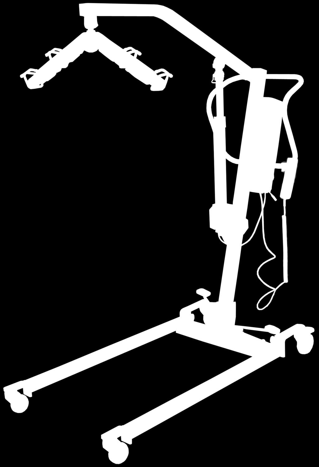
5 2 Intended purpose General The aks-clino II patient hoist (Figure 01) is an active Class I medical product according to EU Council Directive 93/42/EC, Appendix IX. It can be universally used in the entire care sector (except potentially explosive areas). Its use compensates for the disability or incapacity of the patient and makes the working conditions easier for the care personnel. It is provided exclusively for transfer and transport of a patient with restricted mobility caused by illness or disability. Moving the aks-clino II patient hoist is only suitable for short distances inside the residence / sphere of activity of the patient and on one building level. It is only permitted to be used on a flat and level surface. It is intended for short-time use without contact with injured skin and needs a suitable hoist sling for use. The patient is picked up in sitting position as standard; however a lying position is also possible when an aks lying transport clamp and lying transport sling are used. Even picking up a patient from the floor is possible. The aks-clino II is suitable for a patient weight up to maximum 150 kg. The operation is performed by an instructed carer. The aks-clino II is suitable for use at an ambient temperature from 0 C to 40 C, humidity of 20% to 80% and air pressure of 700 hpa to 1060 hpa in normally composed atmospheric air. It may be used in humid rooms such as bathrooms and toilets. Do not use this hoist under a running shower. Syndromes such as osteogenesis imperfecta, osteoporosis or spinal column damage and mental aberration or epileptic attacks can be contraindications. The aks-clino II is only permitted to be used after careful consideration of the individual patient by the doctor and the care personnel. Page 5
6 3 General safety instructions Only use the patient hoist in accordance with its intended purpose, the requirements of the medical products law and all related legal regulations, the occupational health and safety and accident prevention regulations as well as the generally recognised rules of standard engineering practice. Note that the patient hoist is a medical product and the Medical Products Operator Regulations (MPBetreibV) are binding for the operating organisation / user. The requirements for the electrical installation of the room / area where the patient hoist is operated must comply with the state of the art. Only use the patient hoist if you have been instructed about its handling and you have the corresponding expert knowledge. Read the operating manual completely before commissioning in order to avoid damage due to incorrect operation or hazards. It contains important information and instructions which are necessary for the proper operation of the patient hoist. Only use the patient hoist in accordance with the present operating manual. Keep the operating manual safely for possible reference. Include this operating manual with the aks-clino II in the case of change of ownership. Ensure the patient hoist and its accessories are in proper, fault-free condition before every use. If you want to use the patient hoist in combination with other medical products or non-medical products, check whether this product combination is permissible and can be operated safely. Note that the installation, operation, maintenance and repair of the patient hoist must only be performed by suitable qualified personnel. You as the user / owner must ensure (e.g. by corresponding instructions and precautions) that mechanical load of the charging cable (e.g. kinking, pulling, shearing, driving over the cable with the hoist itself or with equipment trolleys) during the charging or room cleaning is avoided. This also applies to cables for other equipment which is used in combination with the patient hoist. Pay attention to compliance with the activation time and the maximum load. These must not be exceeded, otherwise reliable operation can no longer be guaranteed (see Chapter 7 Commissioning and Chapter 21 Technical Data). Protect the aks patient hoist against direct sunlight and heat. Ensure that no moisture penetrates into the electrical system. Charge the batteries at a well ventilated place. The patient hoist is not EX-protected and must not be operated in potentially explosive areas. Note that possible electromagnetic or other influences between the patient hoist and other equipment cannot be ruled out. If there is a risk of interactions, remove the interference source or do not use the patient hoist. Page 6
7 Faults due to the use of mobile communications devices cannot be completely ruled out. Therefore, maintain a safety distance of at least 3.3 m to guarantee reliable operation of the hoist. - See position paper of the German Federal Institute for Drugs and Medical Products (BfArM) (reference No.: 9 / 0508) - Do not leave children in the surroundings of the patient hoist unsupervised. The patient hoist is not a toy! Observe the storage conditions in chapters 13 Shutdown Times and 14 Storage in the case of not using the patient hoist for a long time. In the case of unusual noises, damage or malfunction, the patient hoist must not be further operated. Do not connect the hoist to the charger and contact your authorised dealer. Ensure that only original spare and accessory parts which have been approved for this product are used. These are tested specifically for the product and comply with the existing type approval for spare parts; for accessory parts, they guarantee a safe and functional combination. 4 Scope of delivery The aks patient hoist has already been inspected at the factory for freedom from defects and completeness. Nevertheless, check the product immediately after receipt for possible transport damage. Check whether all items are present using the delivery note and thus that the delivery is complete. Table 01 Carton Contents Quantity Patient hoist aks-clino II aks-clino II 1 Battery pack (removable) 1 Mains battery charger 1 Operating manual 1 Transport clamp (depending on order) - The lying transport clamp with 8-point attachment is packaged separately 1 Hoist sling (depending on order) 1 Page 7
8 5 5.1 Product description Product overview Mains battery charger Connection cable Lifting arm Grab handle Transport clamp with padding Manual control unit mechanical emergency lowering Battery pack Control unit with EMERGENCY STOP button Lift drive Chassis Stand mast Foot pedal for the spreader bar Front castor Figure 01 Rear castor with locking device Page 8
9 5.2 Functional description The aks-clino II is a mobile patient hoist with electrically operated lifting and lowering function. The U-shaped chassis is equipped with four castors of which the rear ones are lockable. The chassis can be spread manually using a foot pedal. Spreading can be required to adjust the chassis to the width of the seating of the patient or to increase the stability. The stand mast is mounted on the chassis and can be folded forwards for transport and storage purposes. An ergonomic grab handle is attached to the stand mast for pushing the patient hoist. The control unit and a removable battery pack are located on the side of the stand mast. The lifting arm holder which can be adjusted using an electric lift drive is mounted at the top end of the stand mast. Various aks transport clamps for the accommodation of the various hoist slings can be attached to the lifting arm. The lifting arm is moved using the manual control unit by the lift drive which is equipped with manual emergency lowering. The necessary electrical energy is provided by a powerful 24 V battery pack which is located on and can be removed from the control unit. This can be charged either on the patient hoist via the mains battery charger or at a separate wall charging station. Page 9

. In doing so, the curved end of the plate slides over the chamfer of the pin.")
10 6 6.1 Assembly Locking plate The aks patient hoist is equipped with a universal bolt and locking plate at several places. This locking plate enables fast installation and removal without tools of individual components, particularly for the assembly and folding of the patient hoist and for attachment and replacement of a transport clamp. The correct installation and removal of Locking plate the locking plate are described below. Installation of the locking plate Push the locking plate into the groove at the end of the pin (Figure 02). In doing so, the curved end of the plate slides over the chamfer of the pin. The locking plate is seated correctly when it audibly engages and can be freely turned in the groove of the pin. Figures 03 and 04 show the incorrect and correct position respectively. Universal bolt Figure 02 incorrect correct Figure 03 Figure 04 Removal of the locking plate Pull the curved end of the plate back somewhat and push the locking plate out of the groove of the pin (Figure 05). Figure Page 10


 and then secure it again using the")
11 Assembly of the hoist Place the chassis with the castors on the floor and brake the rear castors (Figure 06). Figure Remove the universal bolt with locking plate from the hole for the transport lock (Figure 07). Universal bolt 2 Locking plate 1 Figure Upright the stand mast (Figure 08) and then secure it again using the universal bolt and locking plate (Figure 09). Figure 08 Universal bolt 1 Figure 09 Locking plate 2 Page 11

12 4. 5. Remove the cable tie which holds the lifting arm and stand mast together as transport lock. In order to attach the lift drive to the lifting arm, remove the universal bolt with locking plate from the motor retaining plate on the lifting arm. Pay attention to correct fastening of the universal bolts with locking plates (see section 6.1 Locking Plate) for subsequent installation of the lift drive 6. Raise the lifting arm and align the drill hole of the lift tube with that of the motor retaining plate. Fasten the lift drive to the motor retaining plate of the lifting arm by inserting the universal bolt and securing afterwards using the locking plate (Figure 10). Lifting arm Motor retaining plate Universal bolt with locking plate Lift tube Figure For mounting the transport clamp, remove the attached universal bolt with locking plate for transport and the retaining bolt with collar at the end of the lifting arm. Then insert the retaining bolt with collar from below through the holding sleeve of the transport clamp. Fasten the transport clamp with the inserted retaining bolt by connecting it to the universal bolt on the lifting arm and securing with the locking plate against loosening (Figure 11 / 12). Locking plate Universal bolt Lifting arm Figure 11 Retaining bolt with collar Figure 12 Standard transport clamp Page 12
. HS = Manual control unit M1 = Lift drive M2 = not used (blanking plug) AC = Charging socket 2. 3. 4.")
13 7 Commissioning Before commissioning, note that the Medical Products Operator Regulations are binding for the operating organisation / user of medical products. 1. Check the plug connections on the control unit (Figure 13). HS = Manual control unit M1 = Lift drive M2 = not used (blanking plug) AC = Charging socket Charge the battery pack before the first use of the patient hoist. Proceed according to section 8.6 Batteries. Unlock the EMERGENCY STOP button (Figure 13) if it has been pressed by turning clockwise. Finally, establish the safe condition of the patient hoist using the maintenance plan in section 20.2 Maintenance Plan. Charging cable Dummy plug Lift drive Manual control unit yellow LED green LED EMERGENCY STOP button Control unit Figure 13 Charging cable Page 13
14 The motor operated movement is not suitable for continuous operation. The following activation time must not be exceeded: 15% for max. continuous operation of 2 minutes; max. 5 activation cycles per minute Explanation: After the maximum activation time of 2 minutes, there must be a cooling down phase of at least 11 minutes. A maximum of 5 activations per minute is permitted in the maximum activation time. In order to counteract any overload, the control unit is fitted with a self-resetting safety device. If the activation time is exceeded or the minimum cooling time is not achieved, the overload protection automatically switches off the drive system. After an adequate cooling down phase, the overload protection automatically releases the drive system again. For this reason, several electrical functions must not be performed simultaneously for the adjustment of the patient hoist. Page 14

15 8 8.1 Operation Parking brake The parking brakes are important safety elements of a patient hoist. The rear castors are fitted with parking brakes which act directly on the wheels. Press the locking lever down with your foot until it engages to lock the castors. The patient hoist can no longer be moved in this state. Press the locking device upwards to release the castors (Figure 14). Foot brake unbraked braked Figure 14 If the castors should be braked, always lock both castors. When only one castor is locked on a sloping floor, the unlocked wheel rolls downwards around the braked wheel. Depending on the slope of the surface, there is the danger of the patient hoist tipping over sideways. Page 15
16 8.2 Spreader Spreading can be required to adjust the chassis to the width of the seating of the patient or to increase the stability. Press the right foot pedal down with your foot to spread the chassis (Figure 15). Press the left foot pedal down to realign the chassis parallel (Figure 16). In order to be able to spread the chassis legs of the patient hoist more easily, move it slightly forwards and backwards. Ensure there is sufficient freedom of movement for the spreading. Neither objects nor limbs must be located in the adjustment range. Foot pedal Figure 15 Foot pedal Figure EMERGENCY STOP button The power supply to the motor of your patient hoist is disconnected immediately by pressing the red EMERGENCY STOP button on the control unit (Figure 17). This function enables you to avoid damage in emergencies. The button is unlocked again by turning it clockwise (arrow direction). Figure 17 EMERGENCY STOP button Page 16
 at the red fork head of the lift drive and turn the lift tube (as seen from above) clockwise for this. In this way, you lower the patient.")
17 8.4 Mechanical emergency lowering The patient hoist is equipped with mechanical emergency lowering for the case of a defect in electrical parts or complete discharge of the battery pack. Fold up the clamp (Figure 18) at the red fork head of the lift drive and turn the lift tube (as seen from above) clockwise for this. In this way, you lower the patient. Clamp Fork head Lift tube 2 1 Figure Manual control unit The manual control unit is used for controlling the lift drive. It has a rocker switch (Figure 19). Press the left side of the rocker switch (up arrow) to raise the lifting arm and the right side (down arrow) for the lowering. Left button: Raise lifting arm Right button: Lower lifting arm Figure 19 Page 17
18 8.6 Batteries General The batteries used in the aks patient hoists are lead gel batteries. These batteries must be permanently charged (similar to a passenger car battery). There is no memory effect for the batteries. A deep discharge damages the batteries so severely that they become unusable. New, freshly charged batteries have a capacity of approx. 25 lifting cycles under full load. Mains battery charger Connection cable Figure 20 Batteries must be completely charged before their first use. Always charge the batteries at a well ventilated place. Connection Connect the mains battery charger (Figure 20) with the charging cable to the control unit (Figure 21) using the connection cable. Now plug the mains battery charger into a 230 V / 50 Hz mains power socket. The patient hoist does not function with a charger connected to the mains power supply! For the charging, always connect the mains battery charger to the patient hoist first and not to the mains power supply until afterwards. Non-observance can result in damage to the unit. After the charging, disconnect the mains battery charger from the mains power supply first and then from the patient hoist. Page 18

19 Indicator lamps on the control unit Green LED The correct connection of the mains battery charger to the control unit is indicated by the green LED on the control unit (Figure 21). If the green LED does not light, there is no charging voltage present, i.e. the mains battery charger or the connection is defective. Yellow LED The yellow LED indicates the charging process (Figure 21). It also lights for every connection of the mains battery charger. In the case of completely charged batteries, the yellow LED Figure 21 yellow LED green LED Charging cable goes out and the mains battery charger is automatically switched to the standby mode. If the battery capacity is less than a specified value after some time, the mains battery charger switches on again automatically and the yellow indicator lamp is lit again. If the batteries are almost fully charged, flashing of the yellow indicator can happen for a short time. This is not a fault. Charging time and capacity indicator on the manual control unit The batteries of the patient hoist should always be charged during the idle times. Depending on the condition of the batteries, the charging process can take up to 24 hours; however 12 hours are usually sufficient. The batteries should be completely charged at least once per month in order to avoid a deep discharge which can result in destruction of the batteries. If the battery capacity drops below a minimum value, the capacity indicator lamp in the manual control unit (Figure 22) changes from green to red when the buttons are pressed and a warning tone sounds at the same time. In this case, the batteries must be charged immediately. Capacity indicator lamp (green/ red) As long as the green capacity indicator in the manual control unit is lit and the batteries when red are connected for charging, the time until (signal tone) the batteries are fully charged again is only a few hours (fast charge). If the manual control unit indicator changes from green to red, the Figure 22 patient hoist must no longer be operated. A lifting cycle already started can of course be continued to the end. Further operation in this condition (i.e. capacity indicator lamp lit red) results in a deep discharge and can thus result in damage to the batteries. If the batteries are now connected for charging, the charging voltage is reduced for the protection of the batteries. In this condition, the charging time is significantly increased (up to max. 3 days). If the batteries are not completely charged after 3 days, they are defective and must be replaced. Page 19
20 Do not use the aks patient hoist any more for lifting if the capacity control indicator on the control unit, the manual control unit is lit red and/or the warning tone sounds. In the case of non-observance, damage to the batteries cannot be ruled out. Removal and installation of the battery pack The battery pack on the patient hoist can be removed without tools. This gives you the possibility to replace the battery pack quickly or to charge it separately at a wall charging station Reach into the recessed grip on the battery pack from above and pull the unlocking lever up with your fingers (Figure 23). At the same time, pull the battery pack slightly away from the mounting rail and then upward out of the mounting (Figure 23). Proceed in reverse order for installing. Ensure that the locking lever engages in the mounting rail and that the battery pack is firmly on the mounting rail (Figure 24). Recessed grip with unlocking lever Battery pack Mounting rail Control unit Figure 23 correct incorrect Figure 24 Figure 25 Page 20
21 9 9.1 Patient transport Safety instructions Observe the following safety instructions before every lifting / uprighting and conveying of the patient: The care personnel (user) must have the corresponding expert knowledge to select and use a suitable hoist sling. Check the permissibility of the combination of transport clamp and hoist sling based on Chapter 10 Accessories / Combinations before using the patient hoist. Verify the actual maximum load of the combination. In the case of differences between the maximum loads of patient hoist, transport clamp and sling, the lowest maximum load is always mandatory for you. Check the correct sling size and sling form in relation to the patient. Check the safe condition of the sling before every use. The sling must have neither tears in the material nor damaged seams. Check whether the correct loop combination has been attached. All loops have 3 different mounting levels: long - medium - short. Each loop pair (e.g. leg loops, shoulder loops) must only show the following mounting combination: long long, medium medium or short short. Check whether all loops are attached in the mounting hook. Lock the rollers/castors/wheels of the wheelchair, the homecare bed, the stretcher etc. in order to be able to raise and lower the patient safely. In doing so, leave the castors of the patient hoist unbraked. Arrange the patient transport to be as short as possible and never leave the patient hanging unsupervised in the hoist sling. Observe the patient during the transfer. Violent movements of the patient or holding on to objects during the transfer can result in hazards. Only lift the patient as high as is necessary. Keep the hoist slings away from intense heat or open flame; they are not flame retardant. Page 21

22 9.2 Patient transport In order to lift and convey a patient with the aks-clino II, it must have been assembled properly according to Chapter 6 Assembly. Chapter 7 Commissioning must also be noted previously. A suitable hoist sling is also needed for this application. The type and size of the sling always depends on the stature of the patient and the type of use. aks provides a wide range of hoist slings (see Chapter 10 Accessories / Combinations) which are suited to the respective requirements. The following describes attaching an aks standard sling (Figure 26) to a lying patient (Look for descriptions of further slings and applications in the particular user guide of the slings): aks standard sling Shoulder loop Manoeuvring handle Sling back part Leg part Leg loop Figure If the patient is lying on his back, turn him so that he is facing away from you. Fold the aks standard sling in half in the longitudinal direction. Place the aks standard sling with the folded side on the back of the patient. In doing so, the aks logo and the labels must face downwards. Ensure that the bottom edge of the sling back part is on the coccyx and the top edge is on the shoulders of the patient. Now roll the patient over the aks standard sling to the other side. Now pull the folded half of the aks standard sling under the patient and place it properly Now turn the patient back onto his back. The patient is lying correctly on the aks standard sling if his back is completely on the sling back part and the leg supports are next to the thighs. Now raise the back part of the homecare bed until the patient is almost sitting upright. Fold both the leg supports from the outside to the inside around the respective thighs of the patient. Page 22
23 Position your aks patient hoist with the aks standard transport clamp so that the aks standard transport clamp is at eye height in front of the patient. Ensure there is sufficient clearance between the face of the patient and the aks standard transport clamp. Ensure before attaching to the clamp that both the shoulder loops as well as both the leg loops are at the same height. Now hang both the shoulder loops in the outer hooks of the aks standard transport clamp. Afterwards, hang both the leg loops crosswise on the inner hooks. Raise the lifting arm of the aks patient hoist slightly until the leg and shoulder loops are tensioned. Now check whether the aks standard sling is attached correctly and comfortably. You can now lift the patient. Use the manoeuvring handle located on the top edge of the sling back part for easier manoeuvring. Page 23
24 10 Accessories / Combinations Only use original aks accessory parts as accessories (Table 02) because only these are approved by ourselves and guarantee faultless and safe functioning. Accessories: Table 02 Accessories Order No. Standard transport clamp (150 kg, light grey), including padding Lying transport clamp (150 kg, light grey), including padding Lying transport clamp with 8-point attachment (150 kg, light grey) Clamp padding Charger Battery pack Wall charging station for battery pack (without battery pack) aks-dw 150 (digital hoist scales with adapter, adjustable) aks-efw 150 (hoist scales which can be calibrated with adapter and standard transport clamp) Head support for the standard sling and bath sling See Table 03 for other hoist slings Table 03 The aks-clino II has been tested and approved for safe use with the aks transport clamps shown in Table 02 and the aks hoist slings shown in Table 03. The user must have the corresponding expert knowledge to be able to correctly assess the suitability of the sling for the patient and the application. Page 24
25 Product Application / posture S = sitting L = lying A = for uprighting Table 03 Standard transport clamp Lying transport clamp Lying transport clamp (8-point attachment) Standard sling S x x - Standard sling with back reinforcement and head support Comfort sling with integrated head support S x x - S x x - Bath sling S x x - bath sling with back reinforcement and integrated head support comfort bath sling with integrated head support Bath sling aqua blue S x x - S x x - Order No.(sorted by size) (S) (M) (L) (XL) (XXL) (S) (M) (L) (S) (M) (L) (XL) (XXL) (S) (M) (L) (XL) (XXL) (S) (M) (L) (S) (M) (L) (XL) (XXL) S x x (M) Hygienic sling S x x - Comfort hygienic sling S x x - Fast transport sling with breast loop S x x - Lying transport sling (S) (M) (L) (S) (M) (L) (S) (M) (L) L - x (M) Lying transport sling 8-point (without filling material) Seat sling for patients with amputated limbs (without filling material) Bath sling for patients with amputated limbs Uprighting sling (2 single slings) L - - x S x - - L x (M) (L) (XL) (XXL) (M) (L) (M) (L) S x (M) Page 25
26 11 Troubleshooting / fault clearance If a fault occurs and the patient hoist no longer functions, check the malfunction using Table 04. Contact your authorised dealer if the cause of the fault cannot be rectified. Table 04 Fault possible causes Remedy Emergency stop button pressed Unlock emergency stop button Manual control unit cable not plugged in or not plugged in Plug in manual control unit cable aks patient hoist does not lift correctly (LED on the manual control unit does not light) aks patient hoist does not lift (LED on the manual control unit lights green) aks patient hoist does not lift Hoist connected to the charger Battery pack discharged Battery pack defective Drive cable not plugged in or not plugged in correctly Battery pack discharged Wait until the charging process is complete; then disconnect the charger from the hoist Charge battery pack Replace battery pack Plug in drive cable Charge battery pack (LED on the manual control lights red) Battery is not charged (green LED on the control unit does not light) Battery pack defective no correct connection between charging cable and mains battery charger Connection cable or mains battery charger defective Replace battery pack Check plug connections replace defective part Page 26
27 12 Care / cleaning The patient hoist must always be disconnected from the charger for cleaning and disinfection in order to prevent risk of electric shock, fire hazard and functional failure. The existing plug connectors and sockets on the patient hoist are only protected against spray water when plugged together. The patient hoist is suitable for manual cleaning with a moist cloth. Cleaning and care materials suitable for wooden and plastic furniture can be used as cleaning materials. Thereby, observe the following points: Do not use any abrasive agents or cleaning materials containing ammonium chloride. Only use dermatologically tested materials. Do not use any basic and alkaline cleaning agents. Do not use any aggressive cleaning materials (e.g. solvents) or hard brushes etc. Only use alcohol-free and chlorine-free disinfectants and methods from the RKI (Robert-Koch Institut) list or the disinfectants list of the VAH (Verbund für Angewandte Hygiene e.v.) for spraying and wiping disinfection. Observe the instructions and safety precautions of the cleaning and disinfectants materials manufacturers. The electrical components of the patient hoist are protected against spray water according to IPX4. Never clean the patient hoist, particularly the electrical system, with a high pressure cleaner, water hose or in an automatic bed washing system because the surfaces and seals can be damaged and water can penetrate. Page 27
28 13 Shutdown times If the patient hoist is not needed, it should always be connected to the mains battery charger in order to guarantee the full capacity of the batteries for the next use. The integrated charging electronics prevent overcharging of the batteries and switch to trickle charging when the batteries are completely charged. Always charge the batteries at a well ventilated place. 14 Storage Select an as cool as possible and dry storage location for storing the patient hoist. The climatic conditions of the storage location should be an ambient temperature from 0 C to 40 C, relative humidity from 20% to 80% and air pressure from 700 hpa to 1060 hpa in normally composed atmospheric air. Avoid direct sunlight. Use the original packaging for the storage. In the case of long storage, it must be ensured that the batteries are completely charged at least once per month so that no deep discharge occurs. A deep discharge results in destruction of the batteries. Page 28

29 15 Reuse The patient hoist is suitable for reuse. Ensure that the patient hoist has been cleaned according to Chapter 12 Care / Cleaning and serviced according to Chapter 20 Maintenance before the reuse. 16 Service life The service life of the patient hoist basically depends on the number of lifting processes, intended use and regular maintenance. The aks-clino II patient hoist verifiably complies with the endurance functionality of lifting processes required in EN Disposal If the patient hoist has outlived its purpose, the electrical components must be treated as waste electrical equipment according to the WEEE Directive (Waste Electrical and Electronic Equipment) and disposed of properly. This is indicated by the symbol in Figure 27. In the case of electrical equipment brought into circulation as new equipment after 13/08/2005, the owner is legally obligated not to give its electrical components to municipal collecting points but to send them directly to the manufacturer. Our General Terms and Conditions are applicable for the return. Unusable batteries must not be disposed of in domestic waste. These must be disposed of in accordance with the regulations for the return and disposal of used batteries and accumulators. The plastic and metal parts used in the aks-clino II must be separated and disposed of properly. Contact your local disposal company for this. Figure 27 Page 29
30 18 Warranty The aks-clino II patient hoist is distinguished by its long service life and high reliability. Nevertheless, should technical problems arise which cannot be rectified using the measures from Chapter 11 Troubleshooting / Fault Clearance, contact your authorised dealer. The dealer will provide assistance as quickly as possible. We guarantee our aks patient hoists for faultless condition in the context of our sales and delivery conditions. We make a factory warranty of 24 months from date of purchase for material defects. We reserve the right to make technical changes for the purpose of improvement. Refer to the rating plate on the lower end of the stand mast for the model designation and serial number. Non-observance of the operating instructions, improperly carried out maintenance work and technical modifications and additions without the permission of the company aks result in voidance of the warranty and general product liability. Include this operating manual with the aks patient hoist in the case of change of ownership. 19 Declaration of conformity The aks-clino II patient hoist complies with the requirements of the EU Council Directive 93/42/EC Medical Products taking account of the amending Directive 2007/47/EC. The following standards have been applied for the development: EN Medical electrical equipment - Part 1 : General requirements for basic safety and essential performance EN Medical electrical equipment - Part 1-2: General requirements for basic safety and essential performance - Collateral standard: Electromagnetic compatibility - Requirements and tests EN ISO Hoists for the transfer of disabled persons - Requirements and test methods EN Assistive products for persons with disability General requirements and test methods Page 30
31 Maintenance General maintenance instructions The service life of the patient hoist is basically influenced by the handling. In order to ensure safe operation, a visual inspection and functional check according to the maintenance plan must be carried out at least annually by suitable qualified personnel. In Germany, the checks must be made in accordance with the Medical Products law, the Medical Products Operator Regulations and EN in the respective applicable version. The corresponding national requirements are applicable in other countries. If the patient hoist is not regularly maintained properly, safe use is no longer guaranteed. Wear, damage or also loosening of connecting elements can thus not be detected. In order to rule out hazards in advance, e.g. due to damaged insulation on the cables, the patient hoist must be disconnected from the mains battery charger for the visual inspection. In the case of damage to load-bearing parts, electrical cables or parts of the electrical system, the patient hoist, if connected, must be disconnected from the mains battery charger and must no longer be used. In the case of damage and defects, inform your authorised dealer who will replace these parts. Only original aks spare parts and aks accessories which have been approved for this product are permitted to be used, otherwise any warranty and product liability are excluded. You must not make any technical modifications and additions without permission from aks. The Medical Products Operator Regulations are binding for the operator / user of medical products. The operating organisation / user of electrically operated patient hoists is obligated in accordance with the applicable (BGV A3) accident prevention regulations to check this equipment before every start-up, after every repair and otherwise in the course of the annual maintenance by a qualified electrician. Page 31
32 20.2 Maintenance schedule Check the patient hoist according to EN at least annually, before every reuse and after every repair. Check the hoist slings according to EN at least every 6 months. Pos. Check point OK 1 Check of the basic requirements 1.1 Appropriate and safe use (no collision points for the lifting function and during transport) 1.2 Permitted accessories or equipment combination 1.3 Rating plate, manufacturing date and warnings sticker present (see Table 05) 1.4 Presence of operating manual 2 Visual inspection of the mechanical parts (the patient hoist must be disconnected from the charger) 2.1 No unauthorised interventions, modifications or improper handling 2.2 No soiling (in particular the lift tubes) 2.3 No surface damage or corrosion 2.4 No deformation or sheared weld seams 2.5 No mechanical wear 2.6 Connection elements (bolts tightened and pins secured with locking plate) 2.7 Castors: undamaged and fastened 2.8 Spreader mechanism (both rubber caps present on the foot pedal) 2.9 Universal bolt with locking plate (replace universal bolt in the case of signs of wear, e.g. embedding) 2.10 Retaining bolt with collar of the transport clamp (replace in the case of wear, e.g. embedding; the collar height must be at least 4 mm) 2.11 Transport clamp not damaged, with sticker, see Table 05, padding and protective caps 3 Visual inspection of the electrical parts (the patient hoist must be disconnected from the charger) 3.1 Mains battery charger not damaged (case with connector, connection cable, rating plate / lettering) 3.2 Connection cable (damage, routing, risk of getting caught) 3.3 No visible damage of the electrical system. (no cracks on cases, fork heads and lift tubes). 3.4 All sockets on the control unit are closed with connectors or dummy plugs with sealing ring. The sealing rings are not torn or porous. 3.5 The lift drive is securely attached. The mountings of the fork heads on the case and those on the lift tube are secured with the universal bolt and locking plate (see section 6.1 Locking Plate) 3.6 Capacity indicator lamp in the manual control unit. (green = battery capacity OK; red + acoustic alarm = below fast charge limit) Connect mains battery charger no additional sockets, e.g. multiple socket strips used for the connection, - green LED indicates the correct connection of the mains battery charger) 3.8 Charging indicator (yellow LED shows the charging process) 3.9 Note service life of the batteries (batteries must be replaced after 4 years at the latest) 4 Functional check 4.1 All castors can be turned easily and swivelled freely by Both parking brakes can be locked and released without faults 4.3 The battery pack can be removed properly and securely replaced 4.4 The chassis can be spread with the foot pedal to the intended width (dimension p in section 21.2 Data) and aligned parallel again 4.5 The emergency stop button can be pressed and engaged; interrupts any electrically operated movement 4.6 The emergency stop button can be unlocked again by turning it clockwise Page 32
33 4.7 The mechanical emergency lowering functions without faults 4.8 The lift drive is moved over the complete adjustment range (limit switch in both directions, no unusual noises). 4.9 The lifting arm can be moved electrically with the maximum load of 150 kg in the complete lifting range (dimension m in section 21.2 Data); self-locking is present 5 Sling visual inspection 5.1 Sewn-in label (type label) and size marking present and legible 5.2 No damage (general condition) 5.3 No high local wear of the fabric (e.g. cuts, holes or burn marks) 5.4 No contamination / damage from chemicals 5.5 No seams with ruptured, removed or undone stitches Patient hoist overall assessment Patient hoist OK: yes no Test date: Inspector: Signature: Company: Product / Accessory Serial number and date of manufacture next service Transport clamp (please enter type): Sling (please enter type): Notes for the maintenance schedule: If indications of damage / defects arise for these checks, the patient hoist must no longer be operated until they are rectified. Defects / damage must be checked, assessed and repaired by suitable qualified personnel. Checking and assessment for electrical components must only be performed by a qualified electrician. Page 33
34 21 Technical Data 21.1 Rating plates and stickers (see Table 05 for explanations) Figure 28 Page 34


35 Table 05 Rating plates and stickers Pos. Pos. 2 Date of manufacture 1 3 aks-clino II rating plate maximum load 4 5 Safety sign Safety instruction for locking plate 6 Type plates of the usable transport clamps 7 aks-clino II product sticker Page 35
36 21.2 Dimensions drawing Reference body 1 Travel direction Reference body 2 Figure 29 Page 36
37 Table 06 Technical Data a) Maximum range at 600 mm reference height: 675 mm b) Maximum range starting from chassis: 675 mm c) Range from the chassis when spreading the leg supports to 700 mm: 313 mm d1) Castor diameter, back: 100 mm d2) Castor diameter, front: 75 mm e) Overall height: 1290 mm f) Turning diameter: 1443 mm g) Chassis length: 1273 mm k) max. attachment height: 2025 mm l) min. attachment height: 821 mm m) Lifting range: 1204 mm o) min. outer width: 621 mm p) max. inner width: 944 mm q) Inner width for maximum range of the attachment point: 866 mm r) min. inner width: 520 mm t) Height of the chassis: 120 mm u) Clearance of the chassis: 70 mm w) Grab handle width: 452 mm x) Minimum distance from the wall to the attachment point for its maximum height (leg supports spread): 607 mm y) Minimum distance from the wall to the attachment point for its minimum height (leg supports spread): 341 mm z) Minimum distance from the wall to the attachment point for maximum range (leg supports spread): 230 mm overall dimensions (without transport clamp and sling): 38 kg / 39.5 kg Maximum load: 150 kg Operating force of the manual control unit: 2 N Sound power level: 51 db (A) Used Materials: steel (powder coated), commercial plastics such as POM, ABS, PVC, PA6.6 and rubber. - ambient temperature from 0 C to 40 C Climatic conditions: - relative humidity from 20% to 80% - air pressure from 700 hpa to 1060 hpa - normally composed atmospheric air Page 37
: Operating voltage (battery unit): Capacity (battery unit): Protection type (battery unit): Protection type (control unit): Protection type (lift drive): Activation")
 only suitable for dry indoor areas WEEE marking (The device must not be")
38 21.3 Electrical Data Input voltage (charger): Output voltage (charger): Input voltage (lift drive): max. current consumption (lift drive): Operating voltage (battery unit): Capacity (battery unit): Protection type (battery unit): Protection type (control unit): Protection type (lift drive): Activation duration: Electrical Data 230 V AC / 50 Hz / 26 W 24 V AC / 830 ma / 20 VA 24 V DC 9.5 A 24 V DC 4.5 Ah IPx4 IPX4 IPX4 ED 15% for max. continuous operation of 2 minutes; max. 5 switching cycles per minute Explanation of the symbols Protection class II Type B operating manual Attention (safety sign) only suitable for dry indoor areas WEEE marking (The device must not be disposed of with the domestic waste) This product complies with the basic requirements of the Medical Products Directive 93/42/EC Normal washing program; max. washing temperature 60 C do not bleach (new symbol) do not iron no chemical cleaning possible Tumbler drying; dry with reduced thermal load All parts and data are subject to constant further development and can thus be different from the information shown in this document. Page 38
39 Please enter the serial number of your aks patient hoist here: Serial number: Please enter the year of manufacture of your aks patient hoist here: Year of manufacture: Enter the telephone number and name of the contact person of your authorised dealer here: Name: Telephone number: Notes: Page 39
40 aks - aktuelle krankenpflege systeme GmbH Antwerpener Straße Troisdorf Tel.: / Fax.: / aks@aks.de web: Reprints whether in whole or in part are only allowed with the previous permission of the publisher. All rights reserved. We also reserve the right to make technical changes.
aks-efw 300 Fastening set with weighing hanger for hoist scales with EC calibration Operating manual (translation of the original operating manual)
") Fastening set with weighing hanger for hoist scales with EC calibration Operating manual (translation of the original operating manual) Date: 2012_01 Page 2 TABLE OF CONTENTS 1 Introduction 4 2 Intended
Fastening set with weighing hanger for hoist scales with EC calibration Operating manual (translation of the original operating manual) Date: 2012_01 Page 2 TABLE OF CONTENTS 1 Introduction 4 2 Intended
aks-goliath Operating manual (translation of the original operating manual)
") Operating manual (translation of the original operating manual) Date: 03/2007 Dear Customer, thank you for purchasing our hoist. You have acquired a functional hoist with simple handling and the highest
Operating manual (translation of the original operating manual) Date: 03/2007 Dear Customer, thank you for purchasing our hoist. You have acquired a functional hoist with simple handling and the highest
aks-dualo Patient hoist Operating manual
 Patient hoist Operating manual Date: 2012_12 TABLE OF CONTENTS 1 Introduction 3 2 Intended purpose 4 3 General safety instructions 5 4 Scope of delivery 6 5 Product description 7 6 Assembly 11 7 Commissioning
AQUATEC R / AQUATEC F / AQUATEC XL. Bathlift Operating instructions
 AQUATEC R / AQUATEC F / AQUATEC XL Bathlift Operating instructions 1 2 3 4 5 6 7 8 9 10 11 Contents 1 General instructions................. 3 1.1 Introduction......................... 3 1.2 Proper use.........................
KeContact P20. User manual
 KeContact P20 User manual Comments to this manual In this manual you will find warnings against possible dangerous situations. The used symbols apply to the following meanings:!! WARNING! Indicates a potentially
Installation and operating instructions. Solar charge controller MPPT 10 A / 20 A Z Z
 Installation and operating instructions Solar charge controller MPPT 10 A / 20 A EN 1 Contents 1. About these instructions... 3 1.1 Applicability... 3 1.2 Users... 3 1.3 Description of symbols... 3 2.
Molift Mover 180. EN - User manual. BM08101 Rev. D
 Molift Mover 180 EN - User manual BM08101 Rev. D 2016-04-01 English manual Content Molift Mover 180...2 Lifter components...2 About Molift Mover 180...2 General...3 Declaration of conformity...3 Conditions
Molift Mover 300. EN - User manual. BM06101 Rev. F
 Molift Mover 300 EN - User manual BM06101 Rev. F 2016-06-01 English Manual Content Molift Mover 300...2 Lifter components...2 About Molift Mover 300...2 General...3 Declaration of conformity...3 Conditions
Drive Unit e-drive1. Installation instructions 04/2014. English translation of the original German installation instructions
 Drive Unit e-drive1 Installation instructions 04/2014 English translation of the original German installation instructions Contents Foreword... 3 Availability... 3 Structural features in the text... 3
Liko M220 / Liko M230
 Liko M220 / Liko M230 Instruction Guide English 7EN150106-04 2012-03-06 Applies to the following models: Liko M220 Prod. no. 2050010 Liko M230 Prod. no. 2050015 Liko M230 Product Description Liko M220
Instructions for Fitting, Operating and Maintenance Canopy Door RE / (St.: )
") EN Instructions for Fitting, Operating and Maintenance Canopy Door 1 818 012 RE / (St.: 12.2010) 12.2010 ENGLISH Contents 1 Safety Instructions... 3 1.1 Qualified persons... 3 1.2 Symbols and signal words
EN Instructions for Fitting, Operating and Maintenance Canopy Door 1 818 012 RE / (St.: 12.2010) 12.2010 ENGLISH Contents 1 Safety Instructions... 3 1.1 Qualified persons... 3 1.2 Symbols and signal words
Molift Partner 255. EN - User manual. BM03101 Rev. L
 Molift Partner 255 EN - User manual BM03101 Rev. L 2016-06-14 English Manual Content Molift Partner 255...2 Lifter components...2 About Molift Partner 255...2 General...3 Declaration of conformity...3
Mod: KLD6-12/35XLAS-N
 12/2011 Mod: KLD6-12/35XLAS-N Production code: 1914070 INSTRUCTION MANUAL LOGIC LINE PLUS HOOD Reseller Stamp for Warranty Dear customer, Above all, thank you for choosing our product and we would like
Translation of the Original operating instructions Lifting device Z 70 /...
 Translation of the Original operating instructions Lifting device Z 70 /... Content 1. Lifting device / Correct use according to regulations 2. Basic principles 3. General information 4. Special remarks
Molift Mover 205. EN - User manual. BM05101 Rev. L
 Molift Mover 205 EN - User manual BM05101 Rev. L 2016-04-01 English Manual Content Molift Mover 205...2 Lifter components...2 About Molift Mover 205...2 General...3 Declaration of conformity...3 Conditions
MANN+HUMMEL ENTARON XD. Installation and Maintenance Manual. Version 0709
 MANN+HUMMEL ENTARON XD Installation and Maintenance Manual Version 0709 Contact information This installation and maintenance manual is a component part of the scope of delivery. It must be kept in a safe
c-go 24V/6A 24V/8A 24V/12A
 c-go 24V/6A 24V/8A 24V/12A Battery charger GB Instruction manual 1 Index 1. Product description... 2 2. Safety advices... 3 3. Quick start guide... 4 4. Operation... 4 5. Problem solving... 6 6. Specifications...
Operating Instructions
 Operating Instructions Pendant Light Fitting > Contents 1 Contents 1 Contents...2 2 General Information...2 3 General Notes Regarding Safety...3 4 Intended Area of Application...4 5 Technical Data...5
Operating Instructions
 Operating Instructions Ex UPS Combination of > 8265/5 GUBox control panel > 8316 battery box Contents 1 Contents 1 Contents 2 2 General Information 2 3 Safety Instructions 2 4 Conformity to standards 3
Installation and operating instructions. Solar charge controller 10 A / 15 A / 0 A / 30 A PHOTOVOLTAIK - PHOTOVOLTAICS - PHOTOVOLTAIQUE - FOTOVOLTAICA
 PHOTOVOLTAIK - PHOTOVOLTAICS - PHOTOVOLTAIQUE - FOTOVOLTAICA Installation and operating instructions Solar charge controller 10 A / 15 A / 0 A / 30 A EN 74.86 08.4 1. About this manual These operating
SOLAR CHARGE CONTROLLER
 SOLAR CHARGE CONTROLLER SCE 1010 / SCE 1515 / SCE 2020 / SCE 3030 Instruction Manual Please read user manual carefully before use. 1.About this manual These operating instructions are part of the product.
SPARKSCAN1 HIGH VOLTAGE CLAMP OPERATING MANUAL
 SPARKSCAN1 HIGH VOLTAGE CLAMP OPERATING MANUAL MOTORTECH Tools & Test Equipment for Ignition Systems P/N 01.10.019 Rev. 01/2013 Copyright Copyright 2012 MOTORTECH GmbH. All rights reserved. Distribution
EZ Way Shower Trolleys
 EZ Way Shower Trolleys 2000/3000 Operator s Instructions EZ Way, Inc. PO Box 89 Clarinda, IA 51632 1-800-627-8940 www.ezlifts.com Form 2-207 Rev. 12/14/11 The EZ Way Shower trolley is unique with its side-mounted
Owners Manual Unilift
 Owners Manual Unilift Contents Chapter Page Introduction 2 Safety Advise 3 Warranty 4 Using the Unilift 5 Fitting the Sling 6 Lifting and lowering 7 Emergency Controls 8 Battery and Charging Systems 9
HST -LS Interlocking device (Translation of Original Manual)
") Installation and Operating Manual for Components HST -LS Interlocking device (Translation of Original Manual) HST-LS Ident.-No.: 10268 HST-LS Ident.-No.: 10269 HST-LS, pictured Ident-Nr. 10269 The image
Installation and Operating Manual for Components HST -LS Interlocking device (Translation of Original Manual) HST-LS Ident.-No.: 10268 HST-LS Ident.-No.: 10269 HST-LS, pictured Ident-Nr. 10269 The image
GARDENA. N FIN P E I DK S NL F GB D
 GARDENA AccuCut 400 Li Art. 8840 D Betriebsanleitung Operating Instructions F Mode d emploi Coupe bordures NL Instructies voor gebruik S Bruksanvisning freeetrim DK Brugsanvisning freeetrim I Istruzioni
AC 100. Operating instructions Pneumatic Crimper AC 100. Date of issue: 05/2010. Keep for future use!
 Operating instructions Pneumatic Crimper AC 100 Date of issue: 05/2010 Keep for future use! SAFETY SAFETY Basic information The basic prerequisite for ensuring safe use and continuous operation of the
All-in-One Hoist User Manual , , ,
 All-in-One Hoist User Manual 25-20010, 25-20020, 25-20030 25-20040, 25-20050 PDF 5946 Nov-2010 General about the hoist Index General about the hoist 3 Operation Operating instructions 4 Battery charging
Instructions for use Shower stretcher Marina
 Instructions for use Shower stretcher Marina Important: Read these instructions carefully before using the Marina! Date of first use User Name Address Manufactured by: Lopital Nederland B.V. Laarakkerweg
Operating Instructions for Porsche Junior Seat ISOFIX
 Operating Instructions for Porsche Junior Seat ISOFIX 33 Porsche, the Porsche Crest and Tequipment are registered trademarks of Dr. Ing. h.c. F. Porsche AG. Reprinting, even of excerpts, or duplication
SIGMA. User Manual MB8100GB
 SIGMA User Manual Introduction Congratulations on your choice of your new lifting chair. Quality and functionality are keywords for all Handicare lifting chairs. For your own safety, and in order to get
Battery Charger JCB- SCH20LI.2
 Safety and operating manual Battery Charger JCB- SCH20LI.2 ORIGINAL INSTRUCTIONS SAFETY INSTRUCTIONS WARNING: Read all safety warnings and all instructions.failure to follow the warnings and instructions
User Manual TABLE MAGNIFIER TL-70. User-friendly Manual ID: #05007
 User Manual TABLE MAGNIFIER TL-70 MANUAL DEVELOPED IN GERMANY myhansecontrol.com User-friendly Manual ID: #05007 Contents Overview... 4 Device parts... 5 Scope of delivery/device parts...6 Preface... 7
Pallas/150. Stand-aid lifter. User instruction. Important - information. This user instruction must be read before the Pallas 150 is used.
 Pallas/150 Stand-aid lifter User instruction Important - information This user instruction must be read before the Pallas 150 is used. This user instruction is intended for technicians, installers, therapists
STAND MODEL FOR MACH M2
 Mounting instructions Directions for use STAND MODEL FOR MACH M2 Stand lamps: Mach M2... Mach M2 F... Order No. 170 120 1300 Order No. 170 230 1300 GmbH u. Co. KG, Flossmannstrasse 28, D-85560 Ebersberg
 IU0U automatic charger Read these instructions carefully before the installation and commissioning and keep them in a safe place. Pass it on to the buyer in case of the further sale of the system. Contents
Assembly and Operating Instructions
 A35AE FU...A150AE FU en Assembly and Operating Instructions Plug-in drives Important information for: Fitters / Electricians / Users Please forward accordingly! These instructions must be kept safe for
Battery Charger JCB-FCH12Li
 Safety and operating manual Battery Charger JCB-FCH12Li ORIGINAL INSTRUCTIONS SAFETY INSTRUCTIONS WARNING: Read all safety warnings and all instructions.failure to follow the warnings and instructions
Assembly and Maintenance Manual Type AS
 Assembly and Maintenance Manual Type AS Hatschekstr.36 69126 Heidelberg Germany Tel +49(0)6221 30470 Fax +49(0)6221 304731 info@stieber.de www.stieber.de Date of issue: 30.05.2018 GB Revision: 0 U:\EngUsers\!ProduktDoku\1AAA_Einbauerklaerung_Wartungsanleitung_Konformitaetserklaerung\1AAA_Wartungsanleitungen\Orginal_Worddatei\_AS.docx
Catalyser Introduction. 3. Hazard Information. 2. Area of Application. 3.1 Symbology
 ENGLISCH Catalyser 2300-0001 1. Introduction We are pleased with your decision to purchase the Catalyser. Please read the following operating instructions carefully and observe the safety information they
C3 Operating Instructions
 Version 3.1 Stand 09.2014 Robert Bosch (Australia) Pty. Ltd. 1555 Centre Road Clayton, Victoria 3168 C3 Operating Instructions For further information please contact Bosch at: Australia 1300 30 70 40 www.boschautoparts.com.au
Assembly and Maintenance Manual Type ASNU
 Assembly and Maintenance Manual Type ASNU Hatschekstr.36 69126 Heidelberg Germany Tel +49(0)6221 30470 Fax +49(0)6221 304731 info@stieber.de www.stieber.de Date of issue: 30.05.2018 GB Revision: 0 U:\EngUsers\!ProduktDoku\1AAA_Einbauerklaerung_Wartungsanleitung_Konformitaetserklaerung\1AAA_Wartungsanleitungen\Orginal_Worddatei\_ASNU.docx
Operating instructions ErgoPack 600 E
 Operating instructions ErgoPack 600 E Operation of the device is only permitted if the operating instructions have been carefully read and understood before use! Declaration of conformity EU declaration
QA4 Surgery Trolley System Manual Function Operating Instructions
 QA4 Surgery Trolley System Manual Function Operating Instructions Catalogue No. 21310 Anetic Aid Ltd. Queensway Guiseley West Yorkshire, LS20 9JE United Kingdom T +44 (0) 1943 878647 F +44 (0) 1943 870455
RESTWELL RISE & RECLINE ARMCHAIRS OWNER S HANDBOOK PARTS DESCRIPTION
 RESTWELL RISE & RECLINE ARMCHAIRS OWNER S HANDBOOK CONTENTS 1. Introduction 2. Parts Description 3. Personal Safety 4. Installation Instructions 5. Backrest Removal 6. Operating Instructions and Guidelines
NEW SOLAR CHARGE CONTROLLERS
 190 SOLAR CHARGE CONTROLLERS Steca Solarix 2020-x2 Dual battery charge controller The Steca Solarix 2020-x2 is a state-of-the-art dual battery charge controller that is ideal for use in leisure applications.
These operating instructions apply for: NCX 380 NCZ 300 NCX 480 NCZ 370 NCX 580 L NCZ 480 NCX 660 K NCZ 560 NCZ 660 NCZ 800
 Original instructions Operating Instructions for May 2010 Electric Internal Vibrators BA No. 1092E Series NCX and NCZ These operating instructions apply for: NCX 380 NCZ 300 NCX 480 NCZ 370 NCX 580 L NCZ
Battery Charger JCB-FCH20LI2
 Safety and operating manual Battery Charger JCB-FCH20LI2 ORIGINAL INSTRUCTIONS SAFETY INSTRUCTIONS WARNING: Read all safety warnings and all instructions.failure to follow the warnings and instructions
OPERATION & MAINTENANCE INSTRUCTIONS
 AUTOMATIC BATTERY CHARGER / MAINTAINER MODEL NO: CBO9-12 PART NO: 6267025 OPERATION & MAINTENANCE INSTRUCTIONS LS0315 INTRODUCTION Thank you for purchasing this CLARKE product. Before attempting to use
OPERATION & MAINTENANCE INSTRUCTIONS
 AUTOMATIC BATTERY CHARGER / MAINTAINER MODEL NO: CBO9-12 PART NO: 6267025 OPERATION & MAINTENANCE INSTRUCTIONS ORIGINAL INSTRUCTIONS LS0118 - ISS 3 INTRODUCTION Thank you for purchasing this CLARKE product.
Overhead lift Roomer 5200
 USER S MANUAL Overhead lift Roomer 5200 The Roomer 5200 offers you the unique ability to lift and move a patient from one room to another. The lift is equipped with two belts. When transferring from room
Tension Meter. Edition FT 03.E. FT Series. Instruction Manual. Valid as of: Please keep the manual for future reference!
 Tension Meter FT Series S C H M I D T c o n t r o l i n s t r u m e n t s Edition FT 03.E Model FT Instruction Manual Valid as of: 01.09.2011 Please keep the manual for future reference! Contents 1 Warranty
HST-BL-2830MS & HST-BL-2830MS-USA
 HST-BL-2830MS & HST-BL-2830MS-USA Release date: 02/2017 High - System - Technik Im Martelacker 12 D-79588 Efringen-Kirchen Phone 0 76 28-91 11-0 Fax 0 76 28-91 11-90 E-Mail: info@hs-technik.com Web: www.hs-technik.com
TR 2000/3000. Operating manual. Shower Trolleys. Hygiene Equipment Designed for People
 Operating manual Always study this manual carefully before operating the Shower Trolley. Operating instructions and recommended maintenance procedures are explained in the following pages. Only qualified
Eva450EE. Functional inspection. Always read the manual. SystemRoMedic TM. Manual - English
 Eva450EE Manual - English 1 3 4 5 6 7 2 13 11 12 9 1. Boom 2. Mast 3. Handlebar 4. Battery pack 5. Emergency stop 6. Control box 7. Motor for base-width adjustment 8. Rear castors with brakes 9. SlingBar
OPERATION & MAINTENANCE INSTRUCTIONS
 AUTOMATIC BATTERY CHARGER / MAINTAINER MODEL NO: CBO9-6/12 PART NO: 6267020 OPERATION & MAINTENANCE INSTRUCTIONS LS0615 INTRODUCTION Thank you for purchasing this CLARKE product. Before attempting to use
EASY CHARGE Waterproof portable Battery Charger
 EASY CHARGE Waterproof portable Battery Charger 1.1 AND 4.3 AMP MODELS EN NL, DE, FR, ES, IT USER S MANUAL WWW.MASTERVOLT.COM/EASYCHARGE-PORTABLE 10000009117/04 2 EN / EasyCharge 1.1 and 4.3 Amp - User
Adjustable Speaker Mount GRAVIS 8
 Adjustable Speaker Mount GRAVIS 8 User's Manual Translation of the original instructions Important Information, Please Read Before Use! KLING & FREITAG GmbH Junkersstraße 14 D-30179 Hannover TEL +49 (0)
Adjustable Speaker Mount GRAVIS 12
 Adjustable Speaker Mount GRAVIS 12 User's Manual Translation of the original instructions Version 3.3 Released: 19.01.2017 Important Information, Please Read Before Use! KLING & FREITAG GmbH Junkersstraße
Molift Quick Raiser 205
 Molift Quick Raiser 205 EN - User manual BM13001 Rev. C 2018-01-08 English Manual Content Molift Quick Raiser 205...2 Lifter components...2 About Molift Quick Raiser 205...2 General...3 Declaration of
User Manual Rittal PMC UPS 6kVA
 User Manual Rittal PMC UPS 6kVA Germany Rittal GmbH & Co. KG Auf dem Stützelberg D-35745 Herborn Tel.: ++49-27 72-5 05-0 Fax: ++49-27 72-5 05-23 19 Internet: www.rittal.de 26 Contents 1. Introduction...
A company of ThyssenKrupp Elevator. ThyssenKrupp Aufzugswerke. Operating Manual. Oil buffer
 A company of ThyssenKrupp Elevator ThyssenKrupp Aufzugswerke Operating Manual Oil buffer OPERATING MANUAL Printer s imprint All rights reserved. Copyright by: THYSSENKRUPP AUFZUGSWERKE GMBH P.O. box 23
ACROBAT SWING STAND MODEL
 Mounting instructions Directions for use ACROBAT SWING STAND MODEL Dr. Mach GmbH u. Co.KG, Flossmannstrasse 28, D-85560 Ebersberg Tel.: +49 (0)8092 2093 0, Fax +49 (0)8092 2093 50 Internet: www.dr-mach.com,
User guide Operator chair Carl Carl Foot and Carl Heel
 User guide Operator chair Carl Carl Foot 120-00102-00 and Carl Heel 120-00102-01 2007-0004 issue 6 Tel +46- Table of content 1. Operator chair Carl... 3 2. Important - Before use... 3 3. Installation...
Installation and operating instructions. Solar charge controller Solarix MPPT 1010 and Z Z
 Installation and operating instructions Solar charge controller Solarix MPPT 1010 and 2010 EN 730927 Z04 1440 730927 Z04 1440 1 Contents 1. About these instructions...3 1.1 Applicability...3 1.2 Users...3
ACROBAT SWING STAND MODEL
 Mounting instructions Directions for use ACROBAT SWING STAND MODEL Stand lamps: Mach 120... Mach 120F... Mach 130... Mach 130F... Mach LED 120... Mach LED 120F... Mach LED 130... Mach LED 130F... Order
Register your instrument! HeatSealer S100. Operating manual
 00N) manual Register your instrument! www.eppendorf.com/myeppendorf Operating manual Copyright 2015 Eppendorf AG, Germany. All rights reserved, including graphics and images. No part of this publication
Cordless Rechargeable Saw Instructions for Use
 Technical data Voltage: DC 10.8V Weight: 1.25Kg Stroke rate: 0-2100/min Stroke: 15mm Cutting capacity: max diameter in wood 80mm / in soft metal 7mm Charging time: Between 5.0-5.5 Hours Battery: 1.3Ah
Installation and Operating Instructions. Solar System Controller ISC3020
 Installation and Operating Instructions Solar System Controller ISC3020 ABOUT THIS MANUAL These operating instructions come with the product and should be kept with it as a reference to all user s of
EuroScooter OWNER S MANUAL
 EuroScooter OWNER S MANUAL 1 TABLE OF CONTENTS Conformity... 2 Introduction... 2 Scope of delivery... 3 Purpose of use... 3 General safety instructions, warnings and cautions... 3 Safety and traffic regulations...
D Dräger Alcotest 3000 Breath Alcohol Measuring Device
 D Dräger Alcotest 3000 Breath Alcohol Measuring Device Instructions for Use ST-14138-2008_sw.eps Table of Contents For Your Safety....................................... 3 Intended Use..........................................
Before installing this unit, read the operating instructions carefully. Strictly adhere to these operating instructions.
 Instruction Manual ENGLISH Before installing this unit, read the operating instructions carefully. Strictly adhere to these operating instructions. BIBO QUICK START GUIDE Insert the bibo Mouthpiece into
Printed: Doc-Nr: PUB / / 000 / 00
 ORIGINAL OPERATING INSTRUCTIONS Hilti HTE-P 33 dispenser It is essential that the operating instructions are read before the tool is operated for the first time. Always keep these operating instructions
User Manual S Line Bed
 User Manual S Line Bed Important Please read before operation Model SLLS001 2 Contents 1 Essential Information 5 1.1 Technical Specifications 5 1.2 Intended Use 6 1.3 Unintended Use 7 1.4 Transportation
SOLAR CHARGE CONTROLLER N 2010 IN 2011/ N 2012/ N 2014
 SOLAR CHARGE CONTROLLER N 2010 IN 2011/ N 2012/ N 2014 Instruction Manual Please read user manual carefully before use. CE 1.About this manual These operating instructions are part of the product. ~ Read
Instruction manual. RP800 - HYDRAULIC actuator, load 150Kg. RP815 - LINAK actuator, load 150Kg
 HYDRAULIC patient lift RP800 - HYDRAULIC actuator, load 150Kg MA RP800_805_806_ 807_810_811_815 02 A_12-2010 Electric patient lifts RP805 - LINAK actuator, load 150Kg RP806 - HIWIN actuator, load 150Kg
Accessories for Wind Power Inverter WINDY BOY PROTECTION BOX 400 / 500 / 600
 Accessories for Wind Power Inverter WINDY BOY PROTECTION BOX 400 / 500 / 600 Installation Guide WBP-Box-IEN103320 IMEN-WBP-BOX Version 2.0 EN SMA Solar Technology AG Table of Contents Table of Contents
Operating manual. ZSK Automatic Bobbin Winder 230V 50Hz/60/Hz / Z
 Operating manual ZSK Automatic Bobbin Winder 230V 50Hz/60/Hz 574 228 / Z-008-1380 02418V10 [GB] - 2016 Subject to change! Änderungen vorbehalten! ZSK Stickmaschinen GmbH Printed in Germany [ GB ] 02418V10
Operating manual. original operating manual. HDA eco Box 12/24V DC Automatic Dispenser. Translation of the. Item No.:
 Operating manual HDA eco Box 12/24V DC Automatic Dispenser Item No.: 110 500 900 Translation of the original operating manual Important! Copyright The operating manual is always to be read before commissioning
Mobile Shower Commode Chair
 BA No.: 02.07.081/2016-12 REBOTEC Rehabilitationsmittel GmbH PO Box Q541 Queen Victoria Building NSW 1230 rebotec.com.au info@rebotec.com.au User Manual Mobile Shower Commode Chair Hamburg 356.xx.xx Height-adjustable
The Future of Homecare Lifting is Here!
 HYDRAULIC OR BATTERY OPERATED MODEL:400H / 400EL / 400LK The Future of Homecare Lifting is Here! Thank you for choosing the BestLift 400 To better serve you, please record the following information: Dealer
WELDING INVERTER. PEGAS 160 E Smart PEGAS 200 E Smart OPERATING MANUAL. ALFA IN a.s. PEGAS E Smart Manual EN 04
 WELDING INVERTER PEGAS 160 E Smart PEGAS 200 E Smart OPERATING MANUAL PEGAS 160-200 E Smart Manual EN 04 2/12 CONTENT: 1. INTRODUCTION... 3 2. SAFETY INSTRUCTIONS AND WARNINGS... 4 3. TECHNICAL DATA...
Accessibility At Its Best
 Accessibility At Its Best Wheelchair personal lift USER GUIDE & WARRANTY TERMS Veziris H E A L T H C A R E Dear Customer, Thank you for your confidence in purchasing our product. You have just acquired
SGA-440 by Prism Medical
 SGA-440 by Prism Medical Introduction... 2 Overview... 2 Components of the Sit to Stand Lift... 3 Component List... 4 Specifications... 5 Cautions... 6 Assembly Instruction... 7 Operation Charging......12
User manual. Model Mini, Small, Medium and Large
 User manual Model Mini, Small, Medium and Large 2 Contents Introduction..3 CE marking and labels...3 Safety precautions..3 Prior to first use 4 Meywalk 4 parts...4 Joining the top part and bottom frame.5
PURE SINE WAVE DC TO AC POWER INVERTER
 PURE SINE WAVE DC TO AC POWER INVERTER 60S-12A / 60S-24A 60S-12E / 60S-24E 100S-12A / 100S-24A 100S-12E / 100S-24E 150S-12A / 150S-24A 150S-12E / 150S-24E Instruction manual SINE WAVE INVERTER Please read
User s Manual. Automatic Switch-Mode Battery Charger
 User s Manual Automatic Switch-Mode Battery Charger IMPORTANT Read, understand, and follow these safety rules and operating instructions before using this battery charger. Only authorized and trained service
Turner PRO. User manual. BM61099 Rev B
 Turner PRO User manual BM6099 Rev B 06-09- Contents User manual - English - 4 Bruksanvisning - Svenska - 8 Brukermanual - Norsk - Brugsvejledning - Dansk - 6 Käyttöohje - Suomi - 0 Gebrauchsanweisung
TIC 300 PRO. Users Manual Mode d emploi Bedienungshandbuch Manual d uso Manual de uso. Non Contact AC Voltage Detector. High Energy Tic Tracer
 TIC 300 PRO High Energy Tic Tracer Non Contact AC Voltage Detector Users Manual Mode d emploi Bedienungshandbuch Manual d uso Manual de uso TIC 300 PRO High Energy Tic Tracer Non Contact AC Voltage Detector
Installation and Operating Instructions. Solar System Controller ISC3030
 Installation and Operating Instructions Solar System Controller ISC3030 ABOUT THIS MANUAL These operating instructions come with the product and should be kept with it as a reference to all user s of the
OPERATOR. Molift Mover 180. Etac AS Etac Supply Gjøvik Hadelandveien 2 N Gjøvik
 OPERATOR manual Molift Mover 180 Etac AS Etac Supply Gjøvik Hadelandveien 2 N - 2816 Gjøvik BM08101 Molift MOVER 180 English - Rev B 05-2013 Innhold About Molift Mover 180...3 Declaration of conformity...
Instruction manual. CSV 402 caravan power supply. Table of contents
 Instruction manual CSV 402 caravan power supply Table of contents 1 Introduction... 2 2 Safety information... 2 2.1 Significae of the warning signs... 2 2.2 General safety instructions... 2 Application
Instructions for Fitting, Operating and Maintenance
 EN Instructions for Fitting, Operating and Maintenance Retractable Door 1 818 024 RE / 10.2011 ENGLISH Contents 1 Safety Instructions... 3 1.1 Qualified persons... 3 1.2 Symbols and signal words used...
Electric Hi Lo Screen lift Trolley Mount 8960
 Electric Hi Lo Screen lift 750 - Trolley Mount 8960 - Max Capacity 100kg - Min Capacity 5kg - Screens upto 86 WARNING! THIS IS NOT A TOY! WARNING! CHILDREN SHOULD NOT OPERATE LIFT OR HAVE ACCESS TO THE
Original Operating Manual
 matev GmbH Nürnberger Str. 50 90579 Langenzenn T +49 (0) 9101 9087-0 F +49 (0) 9101 9087-20 info@matev.eu www.matev.eu Original Operating Manual Snow blade SRM-FB 120 CD Angle adjustment mechanical Version
Ultrasonic Leak Detector and Seal Control Device SONAPHONE R
 SONOTEC Ultraschallsensorik Halle GmbH Nauendorfer Straße 2 D-06112 Halle/Saale Tel: ++49-(0)345-13317-0 Fax:++49-(0)345-13317-99 http://www.sonotec.de e-mail: SONOTEC@sonotec.de Ultrasonic Leak Detector
TX900. Microwave Leakage Detector. 99 Washington Street Melrose, MA Phone Toll Free
 TX900 Microwave Leakage Detector 99 Washington Street Melrose, MA 02176 Phone 781-665-1400 Toll Free 1-800-517-8431 Visit us at www.testequipmentdepot.com Users Manual TX900 Microwave Leakage Detector
Operator s manual Manuel d utilisation Manual de instrucciones. BLi520x BLi940x
 Operator s manual Manuel d utilisation Manual de instrucciones BLi520x BLi940x Please read the operator s manual carefully and make sure you understand the instructions before using the machine. Lire attentivement
OPERATING INSTRUCTIONS
 Emergency Cord Switch Type PRS Device identification No.: 91.054 033.001, /.101 and /.201 OPERATING INSTRUCTIONS 2 CE Sign and Conformity The device meets the requirements of the valid European and national
Medial Thigh Support installation & user manual
 User Manual for all Spex Medial Thigh Supports (product code begins with 1162- ) Revision: Pommel20170320 S Medial Thigh Support installation & user manual User Name: Serial Number: IMPORTANT CONSUMER