THIS PAGE WAS INTENTIONALLY LEFT BLANK.
|
|
|
- Mercy Lloyd
- 6 years ago
- Views:
Transcription
1
2 THIS PAGE WAS INTENTIONALLY LEFT BLANK.
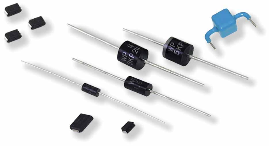
3 Table of Contents Transient Suppression Diodes General Information P4KE Series 400 Watt SA Series 500 Watt P6KE Series 600 Watt KE Series 1500 Watt KP Series 3000 Watt KP Series 5000 Watt KP Series Watt KP Series Watt NEW KP Series Watt NEW P4SMAJ Series 400 Watt Surface Mount P6SMBJ Series 600 Watt Surface Mount SMCJ Series 1500 Watt Surface Mount SMCJ Series 3000 Watt Surface Mount SMCJ Series 5000 Watt Surface Mount Circuit Examples Applications Transient Suppression Diodes World Products, LLC is committed to providing the optimum products for your transient/surge protection problems. Our TVS Diode satisfies the toughest requirements for a low clamping device and provides superior performance in all applications. World Products expands your options... Large selection of equivalents to essentially all TVS Diodes. World Products specifications are designed to provide all of the necessary physical and electrical parameters required for proper component selection. Discover why the first choice in TVS Diodes is WPI. QS 9000 ISO 9002 E N V I R O N M E N TA L S Y S T E M ISO REGISTERED COMPANY SOCIÉTÉ ENREGISTRÉE REGISTERED COMPANY SOCIÉTÉ ENREGISTRÉE TVS Diodes 1
4 General Information TVS Diode Technology World Products Transient Suppression (TVS) Diodes are silicon avalanche devices designed, manufactured, specified and tested according to voltage suppression applications. These devices, with their fast response and low clamping characteristics, protect all MOS technology based devices, hybrids, and other voltage sensitive components. The low clamping factor and pico-second response time of World Products TVS Diodes clamps transient pulses early and maintains them at an acceptable level for their entire duration. In other overvoltage protection devices, response times are delayed by 24nS to 2μs allowing transients to reach dangerous levels. World Products TVS Diodes are designed to meet a 1.30 maximum clamping factor at their rated peak impulse current. This can be compared to clamping factors of 2 to 5 found in other protection devices. TVS Diode Applications TVS Diodes are the optimum choice in protecting computer or data processor circuits and power supplies, airframe avionics and controls, numerically controlled machines, telecom circuits, and many other applications. These devices are designed to protect against transient voltages generated by lightning, electro-static discharge (ESD), and inductive switching. TVS Diode RoHS Compliance All axial TVS Diodes (no suffix code required) and SMD TVS Diodes (denoted by suffix F ) products purchased from World Products, LLC comply to a maximum concentration value of 0.1% by weight in homogeneous materials for lead (Pb), mercury, hexavalent chromium, polybrominated biphenyls (PBB) and polybrominated diphenyl ethers (PBDE) and of 0.01% weight in homogeneous materials for cadmium and are in compliance with Directive 2002/95/EC of the European Parliament and of the Council of 27 January 2003 on the restriction of the use of certain hazardous substances in electrical and electronic equipment (RoHS Directive). Note: Lead(Pb) in high-melting point solder for internal connections is not inhibited by RoHS. (i.e. tin-lead solder alloys containing more than 85%) Selecting the Correct Part Type The following guidelines should be observed in selecting the correct diode: TVS Parameters Application Parameters 1. Stand-off (Vwm) >= Operating (Vop) 2. Peak Pulse (Ippm) >= Source Transient (Is) 3. Clamping (Vc) =< Withstand (Vws) 1. If the stand-off voltage is less than the operating voltage of the application, the diode will continually clamp the circuit voltage. 2. The Peak Pulse (Ippm) is the maximum current the TVS can handle. The source transient current is determined by dividing the peak transient voltage by the source impedance this is often difficult to determine. In many cases, however, this may be obtained from industry standard documents, customer requirements, etc. 3. Determine the maximum voltage level that the protected device can withstand (Vws). Select a suppressor which will clamp the transient at a lower level (Vc). Consider the transient source: lightning, electro-static discharge, inductive switching or nuclear explosion (NEMP). Often, a 1500 watt peak pulse rated device will protect against transients due to secondary lightning effects or inductive switching on power, data and telephone lines. A 500 watt device is sufficient to protect sensitive components against transients generated by electro-static discharge. 2 TVS Diodes
5 General Information (continued) Schematic Symbols Definitions of Terms Unidirectional Bidirectional Vc Clamping : Peak voltage across the suppressor measured at a specific Ippm. (Note: due to thermal, reactive or other effects, peak voltage and peak current are not necessarily coincident in time.) Ipp Peak : Peak current measured using a specified waveform. Ippm Peak : maximum value of peak impulse current (Ipp) applied using a 10 x 1000μs waveform. (Minimum of 10 pulses applied.) Vwm Standoff : working (continuous) DC or peak voltage which may be applied over the standard operating temperature range. (Note: Vwm of a selected device must be greater than or equal to the maximum operating voltage of the line to be protected.) Stand-By : current that flows through the suppressor at rated standoff voltage (Vwm) at a specified temperature. Vbr Breakdown : The voltage measured across the suppressor at a specified DC test current (It). It Test : The specific DC current applied to the suppressor used to determine breakdown voltage (Vbr). Vbr Temperature Coefficient: The ratio of change in breakdown voltage (Vbr) to changes in temperature. Expressed either as millivolts per degree centigrade (mv/ C) or percent change in breakdown voltage per degree centigrade (%Vbr/ C). Cf Clamping Factor: Ratio of the measured clamping voltage (Vc) at specified peak pulse current (Ipp) to breakdown voltage (Vbr) on a specific device. Vc CF = Vbr C Capacitance: Capacitance between the two terminals of a suppressor measured at a specific frequency and bias voltage. Pppm Multiple Peak Pulse Power: Derived by multiplying the maximum clamping voltage (Vc) times the Peak (Ippm). IFSM Forward Surge : Unidirectional devices only. forward current during a 8.3ms half sine wave of AC line frequency (60Hz). TVS Diodes 3
6 General Information (continued) Waveform % of Peak Value µs 1000µs Time - µs Mechanical Characteristics Case: UL94V-0 Molded Epoxy Leads: Tinned Copper Bending Terminal Leads (Through-hole) Types When bending the leads, in order to avoid stress to the area where the leads enter the resinous body, use a tool that clamps the point between the package and the bending point. Improper bending will damage the die or separate the resin from the mounting frame, resulting in a degradation in electrical characteristics or a reliability problem such as poor resistance to moisture. The leads must be bent only once and they should not be bent at an angle of more than 90 C. Leads must be formed before fixing them to a printed circuit board. Never form the leads after soldering. Recommended distances are: 2mm for P4KE and SA series. 3mm for 1.5KE series. 4mm for 3KP, 5KP, 15KP, 20KP and 30KP series. Right Jig or Tool Right Jig or Tool 4 TVS Diodes
7 General Information (continued) Solderability Military Standard 202G Method 208H Heat Resistance of Solder Standard Temperature Profile for Lead Solder (Sn-Pb eutectic) Peak temperature: 240 C Max Standard Temperature Profile for Lead-free Solder Peak temperature: 260 C Max Temperature ( C) Preheating area 150 C±10 C 90s±30s Soldering area 235 C±5 C 10s Temperature ( C) Preheating area 150 C±10 C 90s±30s Soldering area 255 C±5 C 10s Time (s) Time (s) Note: For Lead-free solder, the maximum temperature during mounting processes will be 260 C for both re-flow and flow soldering processes. Soldering of Through-hole Mounting Devices Resistance to soldering heat test is carried out under the condition shown below. Soldering should be completed at a lowest possible temperature for a shortest period. Temp. 260± 5 C Duration 10± 1s General requirements for manual soldering are as follows: Use a soldering iron of 30 watts maximum, that is grounded or with a high insulation resistance. The iron tip is kept away from any resinous body. Attachment should be achieved in not more than 3 seconds. Be sure again not to put an excessive mechanical stress on devices, such as a rough insertion of device into a throughhole, or manual reforming of leads after soldering. Axial Lead Devices Solder Temperature ( C) L= 0 L= 5mm L L Duration of Immersion (sec) $0 TVS Diodes 5
8 General Information (continued) Preformed Lead Drawings R R A A C B C Min. 3.0 B C B B A A D Case type DO-41 package P4KE Series DO-15 package SA Series P6KE Series DO-201AD package 1.5KE Series R-6 package 3KP Series 5KP Series 15KP Series 20KP Series 30KP Series Preformed type Part Marking For Surface Mount Devices Cathode Band M E B C A (mm) B (mm) C (mm) D (mm) R (mm) Range Tolerance Range Tolerance Range Tolerance Range Tolerance Range Tolerance M 11~20 ±0.5 8~20 ± max E 11~20 ±0.5 11~16 ±1.0 4~5 ± max B 7.5 ±0.5 19~22 ± ± max. 2.5~4 typ. C 4.5 ±0.8 18~19 ± ± max. 2.5~4 typ. M 13~20 ±0.5 8~22 ± max E 13~20 ±0.5 11~16 ±1.0 4~5 ± max M 15~20 ±1.0 8~22 ± max E 15~20 ±1.0 10~22 ±1.0 3~5 ± max M 15~20 ±1.0 8~22 ± max M 15~20 ±1.0 8~22 ± max Date Code Example: 5 = 2005, 1 = Jan (Use O for October, N for November, D for December) For Axial Lead Cathode Band Date Code Example: 5 = 2005, 1 = Jan (Use O for October, N for November, D for December) WP XX XXX WP XX XXX = Marking for RoHS Compliance "F" Suffix Type WP XX 1.5KE220A WP XX 1.5KE220CA Part Marking Code Please refer to the specifications tables for each specific part marking code. Optional (internal factory designation) Note: All Axial lead TVS Diodes are RoHS Compliant 6 TVS Diodes
9 General Information (continued) Part Numbering System Axial Type Example Part Number: P4KE 20 C A TR (1) (2) (3) (4) (5) (1) Series: P4KE = 400 Watt SA = 500 Watt P6KE = 600 Watt 1.5KE = 1500 Watt 3KP = 3000 Watt 5KP = 5000 Watt 15KP = Watt 20KP = Watt 30KP = Watt Notes: RoHS Compliance standard. (2) : 20 = 20V Nominal Breakdown For P4KE, P6KE, 1.5KE Standoff For SA, 3KP, 5KP, 15KP, 20KP, 30KP (3) Polarity: Blank = Unidirectional C = Bidirectional (4) Tolerance: Blank = 10% A = 5% (5) Packaging: Blank = Bulk TR = Tape and Reel Surface Mount Example Part Number: P4SMAJ 20 C A F (1) (2) (3) (4) (5) (1) Series: P4SMAJ = 400 Watt Surface Mount P6SMBJ = 600 Watt Surface Mount 1.5SMCJ = 1500 Watt Surface Mount 3.0SMCJ = 3000 Watt Surface Mount 5.0SMCJ = 5000 Watt Surface Mount (2) Stand- Off : 20 = 20V (3) Polarity: Blank = Unidirectional C = Bidirectional (4) Tolerance: Blank = 10% A = 5% Notes: For RoHS Compliance, add suffix F. Standard packaging for Surface Mount parts is Tape and Reel. P4SMAJ = 5000 pieces P6SMBJ = 3000 pieces 1.5SMCJ = 3000 pieces 3.0SMCJ = 3000 pieces 5.0SMCJ = 3000 pieces (5) RoHS Compliance: Blank: No Compliance F: RoHS Compliance TVS Diodes 7
10 P4KE Series 400 Watt P4KE Series Features RoHS Compliance Standard 400 watt peak pulse power dissipation Available in voltages from 6.8V to 440V Unidirectional and Bidirectional Glass passivated junction Low clamping factor Available in bulk or tape and reel (Reel quantity = 5,000 pieces) Each device 100% surge tested Tape and Reel to EIA Standard RS-296-E UL 497B Recognized, File #E Absolute Ratings Parameter Peak pulse power dissipation (PPPM) at 25 C Steady state power dissipation at lead temperature = 75 C (Lead length 3/8 min.) Value 400W 1W Operating and storage temperatures -65 C to C Mechanical Dimensions Diameter 0.8 ± 0.1 mm ± in Diameter 2.35 ± 0.35 mm ± in Minimum 25.4 mm 1.0 in Standard Mounting Pad Layout 1.97 (50.0) 4.65 ± 0.55 mm ± in 0.19 (3.0) Minimum 25.4 mm 1.0 in 1.97 (50.0) D NOTE: Dimension D a.) P4KE (DO-41 Package) (9.2) b.) SA / P6KE (DO-15 Package) (11.6) Hole Diameter a.) (1.1) All dimensions in inches and (millimeters) (2.0) 0.28 (7.0) 8 TVS Diodes
11 P4KE Series 400 Watt (continued) Electrical Characteristics Standoff Breakdown Clamping Peak Ippm# Vwm (Volts) Min Max (ma) (μa) (Volts) (Amperes) P4KE P4KE6.8A P4KE P4KE7.5A P4KE P4KE8.2A P4KE P4KE9.1A P4KE P4KE10A P4KE P4KE11A P4KE P4KE12A P4KE P4KE13A P4KE P4KE15A P4KE P4KE16A P4KE P4KE18A P4KE P4KE20A P4KE P4KE22A P4KE P4KE24A P4KE P4KE27A * = Add C or CA suffix for bidirectional device types. + = For Bidirectional Types Having VWM <= 10V, their ID limit is doubled. # = See General Information for Waveform. TVS Diodes 9
12 P4KE Series 400 Watt (continued) Electrical Characteristics (continued) Standoff Breakdown Clamping Peak Ippm# Vwm (Volts) Min Max (ma) (μa) (Volts) (Amperes) P4KE P4KE30A P4KE P4KE33A P4KE P4KE36A P4KE P4KE39A P4KE P4KE43A P4KE P4KE47A P4KE P4KE51A P4KE P4KE56A P4KE P4KE62A P4KE P4KE68A P4KE P4KE75A P4KE P4KE82A P4KE P4KE91A P4KE P4KE100A P4KE P4KE110A * = Add C or CA suffix for bidirectional device types. + = For Bidirectional Types Having VWM <= 10V, their ID limit is doubled. # = See General Information for Waveform. 10 TVS Diodes
13 P4KE Series 400 Watt (continued) Electrical Characteristics (continued) Standoff Breakdown Clamping Peak Ippm# Vwm (Volts) Min Max (ma) (μa) (Volts) (Amperes) P4KE P4KE120A P4KE P4KE130A P4KE P4KE150A P4KE P4KE160A P4KE P4KE170A P4KE P4KE180A P4KE P4KE200A P4KE P4KE220A P4KE P4KE250A P4KE P4KE300A P4KE P4KE350A P4KE P4KE400A P4KE P4KE440A * = Add C or CA suffix for bidirectional device types. + = For Bidirectional Types Having VWM <= 10V, their ID limit is doubled. # = See General Information for Waveform. TVS Diodes 11
14 SA Series 500 Watt SA Series Features RoHS Compliance Standard 500 watt peak pulse power dissipation Available in voltages from 5.0V to 170V Unidirectional and Bidirectional Glass passivated junction Low clamping factor Available in bulk or tape and reel (Reel quantity = 4,000 pieces) Each device 100% surge tested Tape and Reel to EIA Standard RS-296-E UL 497B Recognized, File #E Absolute Ratings Parameter Peak pulse power dissipation (PPPM) at 25 C Steady state power dissipation at lead temperature = 75 C (Lead length 3/8 min.) Value 500W 1W Operating and storage temperatures -55 C to C Mechanical Dimensions Diameter 0.8 ± 0.1 mm ± in Diameter 2.35 ± 0.35 mm ± in Minimum 25.4 mm 1.0 in Standard Mounting Pad Layout 1.97 (50.0) 4.65 ± 0.55 mm ± in 0.19 (3.0) Minimum 25.4 mm 1.0 in 1.97 (50.0) D NOTE: Dimension D a.) P4KE (DO-41 Package) (9.2) b.) SA / P6KE (DO-15 Package) (11.6) Hole Diameter a.) (1.1) All dimensions in inches and (millimeters) (2.0) 0.28 (7.0) 12 TVS Diodes
15 SA Series 500 Watt (continued) Electrical Characteristics Standoff Breakdown Clamping Peak Ippm# Vwm (Volts) Min Max (ma) (μa) (Volts) (Amperes) SA SA5.0A SA SA6.0A SA SA6.5A SA SA7.0A SA SA7.5A SA SA8.0A SA SA8.5A SA SA9.0A SA SA10A SA SA11A SA SA12A SA SA13A SA SA14A * = Add C or CA suffix for bidirectional device types. + = For Bidirectional Types Having VWM <= 10V, their ID limit is doubled. # = See General Information for Waveform. TVS Diodes 13
16 SA Series 500 Watt (continued) Electrical Characteristics (continued) Standoff Breakdown Clamping Peak Ippm# Vwm (Volts) Min Max (ma) (μa) (Volts) (Amperes) SA SA15A SA SA16A SA SA17A SA SA18A SA SA20A SA SA22A SA SA24A SA SA26A SA SA28A SA SA30A SA SA33A SA SA36A SA SA40A * = Add C or CA suffix for bidirectional device types. + = For Bidirectional Types Having VWM <= 10V, their ID limit is doubled. # = See General Information for Waveform. 14 TVS Diodes
17 SA Series 500 Watt (continued) Electrical Characteristics (continued) Standoff Breakdown Clamping Peak Ippm# Vwm (Volts) Min Max (ma) (μa) (Volts) (Amperes) SA SA43A SA SA45A SA SA48A SA SA51A SA SA54A SA SA58A SA SA60A SA SA64A SA SA70A SA SA75A SA SA78A SA SA85A SA SA90A * = Add C or CA suffix for bidirectional device types. + = For Bidirectional Types Having VWM <= 10V, their ID limit is doubled. # = See General Information for Waveform. TVS Diodes 15
18 SA Series 500 Watt (continued) Electrical Characteristics (continued) Standoff Breakdown Clamping Peak Ippm# Vwm (Volts) Min Max (ma) (μa) (Volts) (Amperes) SA SA100A SA SA110A SA SA120A SA SA130A SA SA150A SA SA160A SA SA170A * = Add C or CA suffix for bidirectional device types. + = For Bidirectional Types Having VWM <= 10V, their ID limit is doubled. # = See General Information for Waveform. 16 TVS Diodes
19
20 P6KE Series 600 Watt P6KE Series Features RoHS Compliance Standard 600 watt peak pulse power dissipation Available in voltages from 6.8V to 400V Unidirectional and Bidirectional Glass passivated junction Low clamping factor Available in bulk or tape and reel (Reel quantity = 4,000 pieces) Each device 100% surge tested Tape and Reel to EIA Standard RS-296-E UL 497B Recognized, File # E (6.8V - 82V) Absolute Ratings Parameter Peak pulse power dissipation (PPPM) at 25 C Value 600W Steady state power dissipation at lead temperature = 75 C (Lead length 3/8 min.) 5W Operating and storage temperatures -55 C to C Mechanical Dimensions Diameter 0.8 ± 0.1 mm ± in Diameter 3.1 ± 0.5 mm ± in Minimum 25.4 mm 1.0 in 6.7 ± 0.9 mm ± in Minimum 25.4 mm 1.0 in Standard Mounting Pad Layout 1.97 (50.0) 0.19 (3.0) 1.97 (50.0) D NOTE: Dimension D a.) P4KE (DO-41 Package) (9.2) b.) SA / P6KE (DO-15 Package) (11.6) Hole Diameter a.) (1.1) All dimensions in inches and (millimeters) (2.0) 0.28 (7.0) 18 TVS Diodes
21 P6KE Series 600 Watt (continued) Electrical Characteristics Standoff Breakdown Clamping Peak Ippm# Vwm (Volts) Min Max (ma) (μa) (Volts) (Amperes) P6KE P6KE6.8A P6KE P6KE7.5A P6KE P6KE8.2A P6KE P6KE9.1A P6KE P6KE10A P6KE P6KE11A P6KE P6KE12A P6KE P6KE13A P6KE P6KE15A P6KE P6KE16A P6KE P6KE18A P6KE P6KE20A P6KE P6KE22A P6KE P6KE24A P6KE P6KE27A * = Add C or CA suffix for bidirectional device types. + = For Bidirectional Types Having VWM <= 10V, their ID limit is doubled. # = See General Information for Waveform. TVS Diodes 19
22 P6KE Series 600 Watt (continued) Electrical Characteristics (continued) Standoff Breakdown Clamping Peak Ippm# Vwm (Volts) Min Max (ma) (μa) (Volts) (Amperes) P6KE P6KE30A P6KE P6KE33A P6KE P6KE36A P6KE P6KE39A P6KE P6KE43A P6KE P6KE47A P6KE P6KE51A P6KE P6KE56A P6KE P6KE62A P6KE P6KE68A P6KE P6KE75A P6KE P6KE82A P6KE P6KE91A P6KE P6KE100A P6KE P6KE110A * = Add C or CA suffix for bidirectional device types. + = For Bidirectional Types Having VWM <= 10V, their ID limit is doubled. # = See General Information for Waveform. 20 TVS Diodes
23 P6KE Series 600 Watt (continued) Electrical Characteristics (continued) Standoff Breakdown Clamping Peak Ippm# Vwm (Volts) Min Max (ma) (μa) (Volts) (Amperes) P6KE P6KE120A P6KE P6KE130A P6KE P6KE150A P6KE P6KE160A P6KE P6KE170A P6KE P6KE180A P6KE P6KE200A P6KE P6KE220A P6KE P6KE250A P6KE P6KE300A P6KE P6KE350A P6KE P6KE400A P6KE P6KE440A P6KE P6KE550A * = Add C or CA suffix for bidirectional device types. + = For Bidirectional Types Having VWM <= 10V, their ID limit is doubled. # = See General Information for Waveform. TVS Diodes 21
24 1.5KE Series 1500 Watt 1.5KE Series Features RoHS Compliance Standard 1500 watt peak pulse power dissipation Available in voltages from 6.8V to 400V Unidirectional and Bidirectional Glass passivated junction Low clamping factor Available in bulk or tape and reel (Reel quantity = 1,200 pieces) Each device 100% surge tested Metal hermetically sealed (DO13) version of this diode is available upon request UL 497B Recognized, File # E (6.8V - 300V) Tape and Reel to EIA Standard RS-296-E Absolute Ratings Parameter Peak pulse power dissipation (PPPM) at 25 C Value 1500W Steady state power dissipation at lead temperature = 75 C (Lead length 3/8 min.) 5W Operating and storage temperatures -55 C to C Mechanical Dimensions Diameter ± mm ± in Diameter mm / mm / in Minimum 27.9 mm 1.10 in 0.32 ± in 8.35 ± 1.15 mm Minimum 27.9 mm 1.10 in Standard Mounting Pad Layout 1.97 (50.0) 1.97 (50.0) D mm / mm / in 0.19 (3.0) NOTE: Dimension D a.) 1.5KE (DO-201 Package) (15.5) b.) 3KP / 5KP /15KP (R-6 Package) (17.1) Hole Diameter a.) (1.5) All dimensions in inches and (millimeters) (2.0) 0.28 (7.0) 22 TVS Diodes
25 1.5KE Series 1500 Watt (continued) Electrical Characteristics Standoff Breakdown Clamping Peak Ippm# Vwm (Volts) Min Max (ma) (μa) (Volts) (Amperes) 1.5KE KE6.8A KE KE7.5A KE KE8.2A KE KE9.1A KE KE10A KE KE11A KE KE12A KE KE13A KE KE15A KE KE16A KE KE18A KE KE20A KE KE22A KE KE24A KE Metal hermetically sealed (DO13) version of this diode is available upon request. * = Add C or CA suffix for bidirectional device types. + = For Bidirectional Types Having VWM <= 10V, their ID limit is doubled. # = See General Information for Waveform. TVS Diodes 23
26 1.5KE Series 1500 Watt (continued) Electrical Characteristics (continued) Standoff Breakdown Clamping Peak Ippm# Vwm (Volts) Min Max (ma) (μa) (Volts) (Amperes) 1.5KE27A KE KE30A KE KE33A KE KE36A KE KE39A KE KE43A KE KE47A KE KE51A KE KE56A KE KE62A KE KE68A KE KE75A KE KE82A KE KE91A KE KE100A Metal hermetically sealed (DO13) version of this diode is available upon request. * = Add C or CA suffix for bidirectional device types. + = For Bidirectional Types Having VWM <= 10V, their ID limit is doubled. # = See General Information for Waveform. 24 TVS Diodes
27 1.5KE Series 1500 Watt (continued) Electrical Characteristics (continued) Standoff Breakdown Clamping Peak Ippm# Vwm (Volts) Min Max (ma) (μa) (Volts) (Amperes) 1.5KE KE110A KE KE120A KE KE130A KE KE150A KE KE160A KE KE170A KE KE180A KE KE200A KE KE220A KE KE250A KE KE300A KE KE350A KE KE400A KE KE440A Metal hermetically sealed (DO13) version of this diode is available upon request. * = Add C or CA suffix for bidirectional device types. + = For Bidirectional Types Having VWM <= 10V, their ID limit is doubled. # = See General Information for Waveform. TVS Diodes 25
28 3KP Series 3000 Watt 3KP Series Features RoHS Compliance Standard 3000 watt peak pulse power dissipation Available in voltages from 10V to 220V Unidirectional and Bidirectional Glass passivated junction Low clamping factor Available in bulk or tape and reel (Reel quantity = 800 pieces) Each device 100% surge tested UL 497B Recognized, File # E Tape and Reel to EIA Standard RS-296-E Absolute Ratings Parameter Peak pulse power dissipation (PPPM) at 25 C Value 3000W Steady state power dissipation at lead temperature = 75 C (Lead length 3/8 min.) 8W Operating and storage temperatures -55 C to C Mechanical Dimensions Diameter 1.25 ± 0.05 mm 0.05 ± in Diameter 8.85 ± 0.25 mm 0.35 ± 0.01 in Minimum 25.4 mm 1.0 in Minimum 25.4 mm 1.0 in Standard Mounting Pad Layout 8.85 ± 0.25 mm 0.35 ± 0.01 in 1.97 (50.0) D 1.97 (50.0) 0.19 (3.0) NOTE: Dimension D a.) 1.5KE (DO-201 Package) (15.5) b.) 3KP / 5KP /15KP (R-6 Package) (17.1) Hole Diameter a.) (1.5) All dimensions in inches and (millimeters) (2.0) 0.28 (7.0) 26 TVS Diodes
29 3KP Series 3000 Watt (continued) Electrical Characteristics Standoff Breakdown Clamping Peak Ippm# Vwm (Volts) Min Max (ma) (μa) (Volts) (Amperes) 3KP KP10A KP KP11A KP KP12A KP KP13A KP KP14A KP KP15A KP KP16A KP KP17A KP KP18A KP KP20A KP KP22A KP KP24A KP KP26A Add C or CA suffix for bidirectional device types. + = For Bidirectional Types Having VWM <= 10V, their ID limit is doubled. # = See General Information for Waveform. TVS Diodes 27
30 3KP Series 3000 Watt (continued) Electrical Characteristics (continued) Standoff Breakdown Clamping Peak Ippm# Vwm (Volts) Min Max (ma) (μa) (Volts) (Amperes) 3KP KP28A KP KP30A KP KP33A KP KP36A KP KP40A KP KP43A KP KP45A KP KP48A KP KP51A KP KP54A KP KP58A KP KP60A KP KP64A KP KP70A KP KP75A Add C or CA suffix for bidirectional device types. + = For Bidirectional Types Having VWM <= 10V, their ID limit is doubled. # = See General Information for Waveform. 28 TVS Diodes
31 3KP Series 3000 Watt (continued) Electrical Characteristics (continued) Standoff Breakdown Clamping Peak Ippm# Vwm (Volts) Min Max (ma) (μa) (Volts) (Amperes) 3KP KP78A KP KP85A KP KP90A KP KP100A KP KP110A KP KP120A KP KP130A KP KP150A KP KP160A KP KP170A KP KP180A KP KP190A KP KP200A KP KP210A KP KP220A Add C or CA suffix for bidirectional device types. + = For Bidirectional Types Having VWM <= 10V, their ID limit is doubled. # = See General Information for Waveform. TVS Diodes 29
32 5KP Series 5000 Watt 5KP Series Features RoHS Compliance Standard 5000 watt peak pulse power dissipation Available in voltages from 5V to 180V Unidirectional and Bidirectional Glass passivated junction Low clamping factor Available in bulk or tape and reel (Reel quantity = 800 pieces) Each device 100% surge tested UL 497B Recognized, File # E Tape and Reel to EIA Standard RS-296-E Absolute Ratings Parameter Peak pulse power dissipation (PPPM) at 25 C Value 5000W Steady state power dissipation at lead temperature = 75 C (Lead length 3/8 min.) 8W Operating and storage temperatures -55 C to C Mechanical Dimensions Diameter 1.25 mm ± 0.05 mm 0.05 in ± in Diameter 8.85 mm ± 0.25 mm 0.35 in ± 0.01 in Minimum 25.4 mm 1.0 in Minimum 25.4 mm 1.0 in Standard Mounting Pad Layout 8.85 mm ± 0.25 mm 0.35 in ± 0.01 in 1.97 (50.0) D 1.97 (50.0) 0.19 (3.0) NOTE: Dimension D a.) 1.5KE (DO-201 Package) (15.5) b.) 3KP / 5KP /15KP (R-6 Package) (17.1) Hole Diameter a.) (1.5) All dimensions in inches and (millimeters) (2.0) 0.28 (7.0) 30 TVS Diodes
33 5KP Series 5000 Watt (continued) Electrical Characteristics Standoff Breakdown Clamping Peak Ippm# Vwm (Volts) Min Max (ma) (μa) (Volts) (Amperes) 5KP KP5.0A KP KP6.0A KP KP6.5A KP KP7.0A KP KP7.5A KP KP8.0A KP KP8.5A KP KP9.0A KP KP10A KP KP11A KP KP12A KP KP13A KP KP14A KP KP15A KP KP16A * = Add C or CA suffix for bidirectional device types. + = For Bidirectional Types Having VWM <= 10V, their ID limit is doubled. # = See General Information for Waveform TVS Diodes 31
34 5KP Series 5000 Watt (continued) Electrical Characteristics (continued) Standoff Breakdown Clamping Peak Ippm# Vwm (Volts) Min Max (ma) (μa) (Volts) (Amperes) 5KP KP17A KP KP18A KP KP20A KP KP22A KP KP24A KP KP26A KP KP28A KP KP30A KP KP33A KP KP36A KP KP40A KP KP43A KP KP45A KP KP48A KP KP51A * = Add C or CA suffix for bidirectional device types. + = For Bidirectional Types Having VWM <= 10V, their ID limit is doubled. # = See General Information for Waveform 32 TVS Diodes
35 5KP Series 5000 Watt (continued) Electrical Characteristics (continued) Standoff Breakdown Clamping Peak Ippm# Vwm (Volts) Min Max (ma) (μa) (Volts) (Amperes) 5KP KP54A KP KP58A KP KP60A KP60B KP KP64A KP KP70A KP KP75A KP KP78A KP KP85A KP KP90A KP KP KP KP KP * = Add C or CA suffix for bidirectional device types. + = For Bidirectional Types Having VWM <= 10V, their ID limit is doubled. # = See General Information for Waveform TVS Diodes 33
36 15KP Series Watt 15KP Series Features RoHS Compliance Standard watt peak pulse power dissipation Avaliable in voltages from 30V to 200V Unidirectional and Bidirectional Glass passivated junction Low clamping factor Each device 100% surge tested Available in bulk or tape and reel (Reel quantity = 800 pieces) UL 497B Recognized, File # E Tape and Reel to EIA Standard RS-296-E Absolute Ratings Parameter Peak pulse power dissipation (PPPM) at 25 C Steady state power dissipation at lead temperature = 75 C (Lead length 3/8 min.) Operating and storage temperatures Mechanical Dimensions Diameter Minimum: 1.2 mm, in : 1.3 mm, in Diameter Minimum: 8.6 mm, in : 9.1 mm, in Value 15000W 8W -55 C to +175 C Minimum: 25.4 mm, 1.0 in Minimum: 25.4 mm, 1.0 in Standard Mounting Pad Layout 1.97 (50.0) 1.97 (50.0) D Minimum: 8.6 mm, in : 9.1 mm, in 0.19 (3.0) NOTE: Dimension D a.) 1.5KE (DO-201 Package) (15.5) b.) 3KP / 5KP /15KP (R-6 Package) (17.1) Hole Diameter a.) (1.5) All dimensions in inches and (millimeters) (2.0) 0.28 (7.0) 34 TVS Diodes
37 15KP Series Watt (continued) Electrical Characteristics Standoff Vwm Breakdown Clamping Peak Ippm# Vwm (Volts) Min (ma) (μa) (Volts) (Amperes) 15KP KP30A KP KP33A KP KP36A KP KP40A KP KP43A KP KP45A KP KP48A KP KP51A KP KP54A KP KP58A KP KP60A KP KP64A KP KP70A KP KP75A KP KP78A * = Add C or CA suffix for bidirectional device types. # = See General Information for Waveform TVS Diodes 35
38 15KP Series Watt (continued) Electrical Characteristics (continued) Standoff Vwm Breakdown Clamping Peak Ippm# Vwm (Volts) Min (ma) (μa) (Volts) (Amperes) 15KP KP85A KP KP90A KP KP KP KP KP KP KP KP KP * = Add C or CA suffix for bidirectional device types. # = See General Information for Waveform 36 TVS Diodes
39
40 20KP Series Watt 20KP Series Features RoHS Compliance Standard watt peak pulse power dissipation Avaliable in voltages from 20V to 300V Unidirectional and Bidirectional Glass passivated junction Low clamping factor Each device 100% surge tested Available in bulk or tape and reel (Reel quantity = 300 pieces) UL 497B Recognized, File # E Tape and Reel to EIA Standard RS-296-E Absolute Ratings Parameter Peak pulse power dissipation (PPPM) at 25 C Steady state power dissipation at lead temperature = 75 C (Lead length 3/8 min.) Operating and storage temperatures Mechanical Dimensions Diameter Minimum: 1.22 mm, in : 1.32 mm, in Diameter Minimum: 8.6 mm, in : 9.1 mm, in Value 20000W 8W -55 C to +175 C Minimum: 25.4 mm, 1.0 in Minimum: 25.4 mm, 1.0 in Standard Mounting Pad Layout 1.97 (50.0) Minimum: 8.6 mm, in : 9.1 mm, in 0.19 (3.0) NOTE: Dimension D a.) 1.5KE (DO-201 Package) (15.5) b.) 3KP / 5KP /15KP / 20KP / 30KP (R-6 Package) (17.1) 1.97 (50.0) D Hole Diameter a.) (1.5) (2.0) All dimensions in inches and (millimeters) 0.28 (7.0) 38 TVS Diodes
41 20KP Series Watt Electrical Characteristics Standoff Vwm Breakdown Clamping Peak Ippm# Vwm (Volts) Min (ma) (μa) (Volts) (Amperes) 20KP20A KP24A KP26A KP28A KP30A KP32A KP34A KP36A KP40A KP44A KP48A KP52A KP56A KP60A KP64A KP68A KP72A KP80A KP88A KP96A KP104A KP112A KP120A KP132A KP144A KP160A KP172A KP180A KP192A KP204A KP216A KP232A KP240A KP256A KP280A KP300A * = Add CA suffix for bidirectional device types. # = See General Information for Waveform TVS Diodes 39
42 30KP Series Watt 30KP Series Features RoHS Compliance Standard watt peak pulse power dissipation Avaliable in voltages from 28V to 288V Unidirectional and Bidirectional Glass passivated junction Low clamping factor Each device 100% surge tested Available in bulk or tape and reel (Reel quantity = 300 pieces) UL 497B Recognized, File # E Tape and Reel to EIA Standard RS-296-E Absolute Ratings Parameter Peak pulse power dissipation (PPPM) at 25 C Steady state power dissipation at lead temperature = 75 C (Lead length 3/8 min.) Operating and storage temperatures Mechanical Dimensions Diameter Minimum: 1.22 mm, in : 1.32 mm, in Diameter Minimum: 8.6 mm, in : 9.1 mm, in Value 30000W 8W -55 C to +175 C Minimum: 25.4 mm, 1.0 in Minimum: 25.4 mm, 1.0 in Standard Mounting Pad Layout 1.97 (50.0) Minimum: 8.6 mm, in : 9.1 mm, in 0.19 (3.0) NOTE: Dimension D a.) 1.5KE (DO-201 Package) (15.5) b.) 3KP / 5KP /15KP / 20KP / 30KP (R-6 Package) (17.1) 1.97 (50.0) D Hole Diameter a.) (1.5) (2.0) All dimensions in inches and (millimeters) 0.28 (7.0) 40 TVS Diodes
43 30KP Series Watt Electrical Characteristics Standoff Vwm Breakdown Clamping Peak Ippm# Vwm (Volts) Min (ma) (μa) (Volts) (Amperes) 30KP28A KP30A KP33A KP36A KP39A KP42A KP43A KP45A KP48A KP51A KP54A KP58A KP60A KP64A KP66A KP70A KP71A KP72A KP75A KP78A KP84A KP90A KP96A KP102A KP108A KP120A KP132A KP144A KP150A KP158A KP160A KP168A KP170A KP180A KP198A KP216A KP240A KP258A KP260A KP270A KP280A KP288A * = Add CA suffix for bidirectional device types. # = See General Information for Waveform TVS Diodes 41
44 P4SMAJ Series 400 Watt Surface Mount P4SMAJ Series Features RoHS Compliance Standard 400 watt peak pulse power dissipation Available in voltages from 5.0V to 188V Unidirectional and bidirectional Glass passivated junction Low clamping factor Available in tape and reel (Reel quantity = 5,000 pieces) Each device 100% surge tested Tape and Reel to EIA Standard RS-481-A UL 497B Recognized, File #E (except for 188V, which is not recognized) Absolute Ratings Parameter Value Peak pulse power dissipation (PPPM) at 25 C 400W Operating and storage temperatures -55 C to C Mechanical Characteristics DO214AC package UL94V-0 Thermoset Epoxy Solder plated terminals Solderable per MIL-STD-750 Method 2026 Mechanical Dimensions ± mm ± in 1.5 ± 0.1 mm ± in 2.7 ± 0.2 mm ± in 2.21 ± mm ± in ± mm ± in 4.3 ± 0.3 mm ± in ± mm ± in 5.04 ± 0.24 mm ± 0.01 in Standard Mounting Pad Layout MAX. (2.69 MAX.) MIN. (2.10 MIN.) MIN. (1.27 MIN.) REF. All dimensions in inches and (millimeters) 42 TVS Diodes
45 P4SMAJ Series 400 Watt Surface Mount (continued) Electrical Characteristics Uni Part Marking Bi Part Marking Standoff Vwm Breakdown Clamping Peak Ippm# (Volts) Min Max (ma) (μa) (Volts) (Amperes) P4SMAJ5.0 HD TD P4SMAJ5.0A HE TE P4SMAJ6.0 HF TF P4SMAJ6.0A HG TG P4SMAJ6.5 HH TH P4SMAJ6.5A HK TK P4SMAJ7.0 HL TL P4SMAJ7.0A HM TM P4SMAJ7.5 HN TN P4SMAJ7.5A HP TP P4SMAJ8.0 HQ TQ P4SMAJ8.0A HR TR P4SMAJ8.5 HS TS P4SMAJ8.5A HT TT P4SMAJ9.0 HU TU P4SMAJ9.0A HV TV P4SMAJ10 HW TW P4SMAJ10A HX TX P4SMAJ11 HY TY P4SMAJ11A HZ TZ P4SMAJ12 ID UD P4SMAJ12A IE UE P4SMAJ13 IF UF P4SMAJ13A IG UG P4SMAJ14 IH UH P4SMAJ14A IK UK * = Add C or CA suffix for bidirectional device types. + = For Bidirectional Types Having VWM <= 10V, their ID limit is doubled. # = See General Information for Waveform. TVS Diodes 43
46 P4SMAJ Series 400 Watt Surface Mount (continued) Electrical Characteristics (continued) Uni Part Marking Bi Part Marking Standoff Vwm Breakdown Clamping Peak Ippm# (Volts) Min Max (ma) (μa) (Volts) (Amperes) P4SMAJ15 IL UL P4SMAJ15A IM UM P4SMAJ16 IN UN P4SMAJ16A IP UP P4SMAJ17 IQ UQ P4SMAJ17A IR UR P4SMAJ18 IS US P4SMAJ18A IT UT P4SMAJ20 IU UU P4SMAJ20A IV UV P4SMAJ22 IW UW P4SMAJ22A IX UX P4SMAJ24 IY UY P4SMAJ24A IZ UZ P4SMAJ26 JD VD P4SMAJ26A JE VE P4SMAJ28 JF VF P4SMAJ28A JG VG P4SMAJ30 JH VH P4SMAJ30A JK VK P4SMAJ33 JL VL P4SMAJ33A JM VM P4SMAJ36 JN VN P4SMAJ36A JP VP P4SMAJ40 JQ VQ P4SMAJ40A JR VR * = Add C or CA suffix for bidirectional device types. + = For Bidirectional Types Having VWM <= 10V, their ID limit is doubled. # = See General Information for Waveform. 44 TVS Diodes
47 P4SMAJ Series 400 Watt Surface Mount (continued) Electrical Characteristics (continued) Uni Part Marking Bi Part Marking Standoff Vwm Breakdown Clamping Peak Ippm# (Volts) Min Max (ma) (μa) (Volts) (Amperes) P4SMAJ43 JS VS P4SMAJ43A JT VT P4SMAJ45 JU VU P4SMAJ45A JV VV P4SMAJ48 JW VW P4SMAJ48A JX VX P4SMAJ51 JY VY P4SMAJ51A JZ VZ P4SMAJ54 RD WD P4SMAJ54A RE WE P4SMAJ58 RF WF P4SMAJ58A RG WG P4SMAJ60 RH WH P4SMAJ60A RK WK P4SMAJ64 RL WL P4SMAJ64A RM WM P4SMAJ70 RN WN P4SMAJ70A RP WP P4SMAJ75 RQ WQ P4SMAJ75A RR WR P4SMAJ78 RS WS P4SMAJ78A RT WT P4SMAJ85 RU WU P4SMAJ85A RV WV P4SMAJ90 RW WW P4SMAJ90A RX WX * = Add C or CA suffix for bidirectional device types. + = For Bidirectional Types Having VWM <= 10V, their ID limit is doubled. # = See General Information for Waveform. TVS Diodes 45
48 P4SMAJ Series 400 Watt Surface Mount (continued) Electrical Characteristics (continued) Uni Part Marking Bi Part Marking Standoff Vwm Breakdown Clamping Peak Ippm# (Volts) Min Max (ma) (μa) (Volts) (Amperes) P4SMAJ100 RY WY P4SMAJ100A RZ WZ P4SMAJ110 SD XD P4SMAJ110A SE XE P4SMAJ120 SF XF P4SMAJ120A SG XG P4SMAJ130 SH XH P4SMAJ130A SK XK P4SMAJ150 SL XL P4SMAJ150A SM XM P4SMAJ160 SN XN P4SMAJ160A SP XP P4SMAJ170 SQ XQ P4SMAJ170A SR XR P4SMAJ188A SS VS * = Add C or CA suffix for bidirectional device types. + = For Bidirectional Types Having VWM <= 10V, their ID limit is doubled. # = See General Information for Waveform. 46 TVS Diodes
49
50 P6SMBJ Series 600 Watt Surface Mount P6SMBJ Series Features RoHS Compliance Standard 600 watt peak pulse power dissipation Available in voltages from 5.0V to 170V Unidirectional and bidirectional Glass passivated junction Low clamping factor Available in tape and reel (Reel quantity = 3,000 pieces) Each device 100% surge tested Tape and Reel to EIA Standard RS-481-A UL 497B Recognized, File # E (5.0V - 75V) Absolute Ratings Parameter Peak pulse power dissipation (PPPM) at 25 C 600W Steady state power dissipation at 25 C 5W Operating and storage temperatures -55 C to C Value Mechanical Characteristics DO214AA package UL94V-0 Thermoset Epoxy Solder plated terminals Solderable per MIL-STD-750 Method 2026 Mechanical Dimensions ± mm ± in ± mm ± in ± mm 0.17 ± 0.01 in 3.62 ± 0.32 mm ± in ± mm 0.09 ± in ± mm ± in ± mm ± in 5.40 ± 0.19 mm ± in Standard Mounting Pad Layout MAX. (2.69 MAX.) MIN. (2.10 MIN.) MIN. (1.27 MIN.) REF. All dimensions in inches and (millimeters) 48 TVS Diodes
51 P6SMBJ Series 600 Watt Surface Mount (continued) Electrical Characteristics Uni Part Marking Bi Part Marking Standoff Vwm Breakdown Clamping Peak Ippm# (Volts) Min Max (ma) (μa) (Volts) (Amperes) P6SMBJ5.0 KD AD P6SMBJ5.0A KE AE P6SMBJ6.0 KF AF P6SMBJ6.0A KG AG P6SMBJ6.5 KH AH P6SMBJ6.5A KK AK P6SMBJ7.0 KL AL P6SMBJ7.0A KM AM P6SMBJ7.5 KN AN P6SMBJ7.5A KP AP P6SMBJ8.0 KQ AQ P6SMBJ8.0A KR AR P6SMBJ8.5 KS AS P6SMBJ8.5A KT AT P6SMBJ9.0 KU AU P6SMBJ9.0A KV AV P6SMBJ10 KW AW P6SMBJ10A KX AX P6SMBJ11 KY AY P6SMBJ11A KZ AZ P6SMBJ12 LD BD P6SMBJ12A LE BE P6SMBJ13 LF BF P6SMBJ13A LG BG P6SMBJ14 LH BH P6SMBJ14A LK BK * = Add C or CA suffix for bidirectional device types. + = For Bidirectional Types Having VWM <= 10V, their ID limit is doubled. # = See General Information for Waveform. TVS Diodes 49
52 P6SMBJ Series 600 Watt Surface Mount (continued) Electrical Characteristics (continued) Uni Part Marking Bi Part Marking Standoff Vwm Breakdown Clamping Peak Ippm# (Volts) Min Max (ma) (μa) (Volts) (Amperes) P6SMBJ15 LL BL P6SMBJ15A LM BM P6SMBJ16 LN BN P6SMBJ16A LP BP P6SMBJ17 LQ BQ P6SMBJ17A LR BR P6SMBJ18 LS BS P6SMBJ18A LT BT P6SMBJ20 LU BU P6SMBJ20A LV BV P6SMBJ22 LW BW P6SMBJ22A LX BX P6SMBJ24 LY BY P6SMBJ24A LZ BZ P6SMBJ26 MD CD P6SMBJ26A ME CE P6SMBJ28 MF CF P6SMBJ28A MG CG P6SMBJ30 MH CH P6SMBJ30A MK CK P6SMBJ33 ML CL P6SMBJ33A MM CM P6SMBJ36 MN CN P6SMBJ36A MP CP P6SMBJ40 MQ CQ P6SMBJ40A MR CR * = Add C or CA suffix for bidirectional device types. + = For Bidirectional Types Having VWM <= 10V, their ID limit is doubled. # = See General Information for Waveform. 50 TVS Diodes
53 P6SMBJ Series 600 Watt Surface Mount (continued) Electrical Characteristics (continued) Uni Part Marking Bi Part Marking Standoff Vwm Breakdown Clamping Peak Ippm# (Volts) Min Max (ma) (μa) (Volts) (Amperes) P6SMBJ43 MS CS P6SMBJ43A MT CT P6SMBJ45 MU CU P6SMBJ45A MV CV P6SMBJ48 MW CW P6SMBJ48A MX CX P6SMBJ51 MY CY P6SMBJ51A MZ CZ P6SMBJ54 ND DD P6SMBJ54A NE DE P6SMBJ58 NF DF P6SMBJ58A NG DG P6SMBJ60 NH DH P6SMBJ60A NK DK P6SMBJ64 NL DL P6SMBJ64A NM DM P6SMBJ70 NN DN P6SMBJ70A NP DP P6SMBJ75 NQ DQ P6SMBJ75A NR DR P6SMBJ78 NS DS P6SMBJ78A NT DT P6SMBJ85 NU DU P6SMBJ85A NV DV P6SMBJ90 NW DW P6SMBJ90A NX DX * = Add C or CA suffix for bidirectional device types. + = For Bidirectional Types Having VWM <= 10V, their ID limit is doubled. # = See General Information for Waveform. TVS Diodes 51
54 P6SMBJ Series 600 Watt Surface Mount (continued) Electrical Characteristics (continued) Uni Part Marking Bi Part Marking Standoff Vwm Breakdown Clamping Peak Ippm# (Volts) Min Max (ma) (μa) (Volts) (Amperes) P6SMBJ100 NY DY P6SMBJ100A NZ DZ P6SMBJ110 PD ED P6SMBJ110A PE EE P6SMBJ120 PF EF P6SMBJ120A PG EG P6SMBJ130 PH EH P6SMBJ130A PK EK P6SMBJ150 PL EL P6SMBJ150A PM EM P6SMBJ160 PN EN P6SMBJ160A PP EP P6SMBJ170 PQ EQ P6SMBJ170A PR ER * = Add C or CA suffix for bidirectional device types. + = For Bidirectional Types Having VWM <= 10V, their ID limit is doubled. # = See General Information for Waveform. 52 TVS Diodes
55
56 1.5SMCJ Series 1500 Watt Surface Mount 1.5SMCJ Series Features RoHS Compliance Standard 1500 watt peak pulse power dissipation Available in voltages from 5.0V to 170V Unidirectional and bidirectional Glass passivated junction Low clamping factor Available in tape and reel (Reel quantity = 3,000 pieces) Each device 100% surge tested UL 497B Recognized, File # E Tape and Reel to EIA Standard RS-481-A Absolute Ratings Parameter Value Peak pulse power dissipation (PPPM) at 25 C 1500W Operating and storage temperatures -55 C to C Mechanical Characteristics DO214AB package UL94V-0 Thermoset Epoxy Solder plated terminals Solderable per MIL-STD-750 Method 2026 Mechanical Dimensions ± mm ± in mm mm in in 6.86 ± 0.24 mm 0.27 ± 0.01 in 5.9 ± 0.32 mm ± in 2.31 ± 0.31 mm ± in ± mm ± in 7.94 ± 0.19 mm ± in mm mm in in Standard Mounting Pad Layout MAX. (4.69 MAX.) MIN. (3.07 MIN.) MIN. (1.52 MIN.) REF. All dimensions in inches and (millimeters) 54 TVS Diodes
57 1.5SMCJ Series 1500 Watt Surface Mount (continued) Electrical Characteristics Uni Part Marking Bi Part Marking Standoff Vwm Breakdown Clamping Peak Ippm# (Volts) Min Max (ma) (μa) (Volts) (Amperes) 1.5SMCJ5.0 GDD BDD SMCJ5.0A GDE BDE SMCJ6.0 GDF BDF SMCJ6.0A GDG BDG SMCJ6.5 GDH BDH SMCJ6.5A GDK BDK SMCJ7.0 GDL BDL SMCJ7.0A GDM BDM SMCJ7.5 GDN BDN SMCJ7.5A GDP BDP SMCJ8.0 GDQ BDQ SMCJ8.0A GDR BDR SMCJ8.5 GDS BDS SMCJ8.5A GDT BDT SMCJ9.0 GDU BDU SMCJ9.0A GDV BDV SMCJ10 GDW BDW SMCJ10A GDX BDX SMCJ11 GDY BDY SMCJ11A GDZ BDZ SMCJ12 GED BED SMCJ12A GEE BEE SMCJ13 GEF BEF SMCJ13A GEG BEG SMCJ14 GEH BEH SMCJ14A GEK BEK * = Add C or CA suffix for bidirectional device types. + = For Bidirectional Types Having VWM <= 10V, their ID limit is doubled. # = See General Information for Waveform. TVS Diodes 55
58 1.5SMCJ Series 1500 Watt Surface Mount (continued) Electrical Characteristics (continued) Uni Part Marking Bi Part Marking Standoff Vwm Breakdown Clamping Peak Ippm# (Volts) Min Max (ma) (μa) (Volts) (Amperes) 1.5SMCJ15 GEL BEL SMCJ15A GEM BEM SMCJ16 GEN BEN SMCJ16A GEP BEP SMCJ17 GEQ BEQ SMCJ17A GER BER SMCJ18 GES BES SMCJ18A GET BET SMCJ20 GEU BEU SMCJ20A GEV BEV SMCJ22 GEW BEW SMCJ22A GEX BEX SMCJ24 GEY BEY SMCJ24A GEZ BEZ SMCJ26 GFD BFD SMCJ26A GFE BFE SMCJ28 GFF BFF SMCJ28A GFG BFG SMCJ30 GFH BFH SMCJ30A GFK BFK SMCJ33 GFL BFL SMCJ33A GFM BFM SMCJ36 GFN BFN SMCJ36A GFP BFP SMCJ40 GFQ BFQ SMCJ40A GFR BFR * = Add C or CA suffix for bidirectional device types. + = For Bidirectional Types Having VWM <= 10V, their ID limit is doubled. # = See General Information for Waveform. 56 TVS Diodes
59 1.5SMCJ Series 1500 Watt Surface Mount (continued) Electrical Characteristics (continued) Uni Part Marking Bi Part Marking Standoff Vwm Breakdown Clamping Peak Ippm# (Volts) Min Max (ma) (μa) (Volts) (Amperes) 1.5SMCJ43 GFS BFS SMCJ43A GFT BFT SMCJ45 GFU BFU SMCJ45A GFV BFV SMCJ48 GFW BFW SMCJ48A GFX BFX SMCJ51 GFY BFY SMCJ51A GFZ BFZ SMCJ54 GGD BGD SMCJ54A GGE BGE SMCJ58 GGF BGF SMCJ58A GGG BGG SMCJ60 GGH BGH SMCJ60A GGK BGK SMCJ64 GGL BGL SMCJ64A GGM BGM SMCJ70 GGN BGN SMCJ70A GGP BGP SMCJ75 GGQ BGQ SMCJ75A GGR BGR SMCJ78 GGS BGS SMCJ78A GGT BGT SMCJ85 GGU BGU SMCJ85A GGV BGV SMCJ90 GGW BGW SMCJ90A GGX BGX * = Add C or CA suffix for bidirectional device types. + = For Bidirectional Types Having VWM <= 10V, their ID limit is doubled. # = See General Information for Waveform. TVS Diodes 57
60 1.5SMCJ Series 1500 Watt Surface Mount (continued) Electrical Characteristics (continued) Uni Part Marking Bi Part Marking Standoff Vwm Breakdown Clamping Peak Ippm# (Volts) Min Max (ma) (μa) (Volts) (Amperes) 1.5SMCJ100 GGY BGY SMCJ100A GGZ BGZ SMCJ110 GHD BHD SMCJ110A GHE BHE SMCJ120 GHF BHF SMCJ120A GHG BHG SMCJ130 GHH BHH SMCJ130A GHK BHK SMCJ150 GHL BHL SMCJ150A GHM BHM SMCJ160 GHN BHN SMCJ160A GHP BHP SMCJ170 GHQ BHQ SMCJ170A GHR BHR * = Add C or CA suffix for bidirectional device types. + = For Bidirectional Types Having VWM <= 10V, their ID limit is doubled. # = See General Information for Waveform. 58 TVS Diodes
61
62 3.0SMCJ Series 3000 Watt Surface Mount 3.0SMCJ Series Features RoHS Compliance Standard 3000 watt peak pulse power dissipation Available in voltages from 5.0V to 170V Unidirectional and bidirectional Glass passivated junction Low clamping factor Available in tape and reel (Reel quantity = 3,000 pieces) Each device 100% surge tested UL 497B Recognized, File # E Tape and Reel to EIA Standard RS-481-A Absolute Ratings Parameter Value Peak pulse power dissipation (PPPM) at 25 C 3000W Operating and storage temperatures -55 C to C Mechanical Characteristics DO214AB package UL94V-0 Thermoset Epoxy Solder plated terminals Solderable per MIL-STD-750 Method 2026 Mechanical Dimensions ± mm ± in mm mm in in 6.86 ± 0.24 mm 0.27 ± 0.01 in 5.9 ± 0.32 mm ± in 2.31 ± 0.31 mm ± in ± mm ± in 7.94 ± 0.19 mm ± in mm mm in in Standard Mounting Pad Layout MAX. (4.69 MAX.) MIN. (3.07 MIN.) MIN. (1.52 MIN.) REF. All dimensions in inches and (millimeters) 60 TVS Diodes
63 3.0SMCJ Series 3000 Watt Surface Mount (continued) Electrical Characteristics Uni Part Marking Bi Part Marking Standoff Vwm Breakdown Clamping Peak Ippm# (Volts) Min Max (ma) (μa) (Volts) (Amperes) 3.0SMCJ5.0 HDD IDD SMCJ5.0A HDE IDE SMCJ6.0 HDF IDF SMCJ6.0A HDG IDG SMCJ6.5 HDH IDH SMCJ6.5A HDK IDK SMCJ7.0 HDL IDL SMCJ7.0A HDM IDM SMCJ7.5 HDN IDN SMCJ7.5A HDP IDP SMCJ8.0 HDQ IDQ SMCJ8.0A HDR IDR SMCJ8.5 HDS IDS SMCJ8.5A HDT IDT SMCJ9.0 HDU IDU SMCJ9.0A HDV IDV SMCJ10 HDW IDW SMCJ10A HDX IDX SMCJ11 HDY IDY SMCJ11A HDZ IDZ SMCJ12 HED IED SMCJ12A HEE IEE SMCJ13 HEF IEF SMCJ13A HEG IEG SMCJ14 HEH IEH SMCJ14A HEK IEK * = Add C or CA suffix for bidirectional device types. + = For Bidirectional Types Having VWM <= 10V, their ID limit is doubled. # = See General Information for Waveform. TVS Diodes 61
64 3.0SMCJ Series 3000 Watt Surface Mount (continued) Electrical Characteristics (continued) Uni Part Marking Bi Part Marking Standoff Vwm Breakdown Clamping Peak Ippm# (Volts) Min Max (ma) (μa) (Volts) (Amperes) 3.0SMCJ15 HEL IEL SMCJ15A HEM IEM SMCJ16 HEN IEN SMCJ16A HEP IEP SMCJ17 HEQ IEQ SMCJ17A HER IER SMCJ18 HES IES SMCJ18A HET IET SMCJ20 HEU IEU SMCJ20A HEV IEV SMCJ22 HEW IEW SMCJ22A HEX IEX SMCJ24 HEY IEY SMCJ24A HEZ IEZ SMCJ26 HFD IFD SMCJ26A HFE IFE SMCJ28 HFF IFF SMCJ28A HFG IFG SMCJ30 HFH IFH SMCJ30A HFK IFK SMCJ33 HFL IFL SMCJ33A HFM IFM SMCJ36 HFN IFN SMCJ36A HFP IFP SMCJ40 HFQ IFQ SMCJ40A HFR IFR * = Add C or CA suffix for bidirectional device types. + = For Bidirectional Types Having VWM <= 10V, their ID limit is doubled. # = See General Information for Waveform. 62 TVS Diodes
65 3.0SMCJ Series 3000 Watt Surface Mount (continued) Electrical Characteristics (continued) Uni Part Marking Bi Part Marking Standoff Vwm Breakdown Clamping Peak Ippm# (Volts) Min Max (ma) (μa) (Volts) (Amperes) 3.0SMCJ43 HFS IFS SMCJ43A HFT IFT SMCJ45 HFU IFU SMCJ45A HFV IFV SMCJ48 HFW IFW SMCJ48A HFX IFX SMCJ51 HFY IFY SMCJ51A HFZ IFZ SMCJ54 HGD IGD SMCJ54A HGE IGE SMCJ58 HGF IGF SMCJ58A HGG IGG SMCJ60 HGH IGH SMCJ60A HGK IGK SMCJ64 HGL IGL SMCJ64A HGM IGM SMCJ70 HGN IGN SMCJ70A HGP IGP SMCJ75 HGQ IGQ SMCJ75A HGR IGR SMCJ78 HGS IGS SMCJ78A HGT IGT SMCJ85 HGU IGU SMCJ85A HGV IGV SMCJ90 HGW IGW SMCJ90A HGX IGX * = Add C or CA suffix for bidirectional device types. + = For Bidirectional Types Having VWM <= 10V, their ID limit is doubled. # = See General Information for Waveform. TVS Diodes 63
66 3.0SMCJ Series 3000 Watt Surface Mount (continued) Electrical Characteristics (continued) Uni Part Marking Bi Part Marking Standoff Vwm Breakdown Clamping Peak Ippm# (Volts) Min Max (ma) (μa) (Volts) (Amperes) 3.0SMCJ100 HGY IGY SMCJ100A HGZ IGZ SMCJ110 HHD IHD SMCJ110A HHE IHE SMCJ120 HHF IHF SMCJ120A HHG IHG SMCJ130 HHH IHH SMCJ130A HHK IHK SMCJ150 HHL IHL SMCJ150A HHM IHM SMCJ160 HHN IHN SMCJ160A HHP IHP SMCJ170 HHQ IHQ SMCJ170A HHR IHR * = Add C or CA suffix for bidirectional device types. + = For Bidirectional Types Having VWM <= 10V, their ID limit is doubled. # = See General Information for Waveform. 64 TVS Diodes
67
68 5.0SMCJ Series 5000 Watt Surface Mount 5.0SMCJ Series Features RoHS Compliance Standard 5000 watt peak pulse power dissipation Available in voltages from 11V to 170V Unidirectional and bidirectional Glass passivated junction Low clamping factor Available in tape and reel (Reel quantity = 3,000 pieces) Each device 100% surge tested UL 497B Recognized, File # E (PENDING) Tape and Reel to EIA Standard RS-481-A Absolute Ratings Parameter Value Peak pulse power dissipation (PPPM) at 25 C 5000W Operating and storage temperatures -55 C to C Mechanical Characteristics DO214AB package UL94V-0 Thermoset Epoxy Solder plated terminals Solderable per MIL-STD-750 Method 2026 Mechanical Dimensions ± mm ± in mm mm in in 6.86 ± 0.24 mm 0.27 ± 0.01 in 5.9 ± 0.32 mm ± in 2.31 ± 0.31 mm ± in ± mm ± in 7.94 ± 0.19 mm ± in mm mm in in Standard Mounting Pad Layout MAX. (4.69 MAX.) MIN. (3.07 MIN.) MIN. (1.52 MIN.) REF. All dimensions in inches and (millimeters) 66 TVS Diodes
69 5.0SMCJ Series 5000 Watt Surface Mount Electrical Characteristics (continued) Part Number Uni Part Marking Bi Part Marking Standoff Vwm Clamping Peak Ippm# (Volts) Min Max (ma) (μa) (Volts) (Amperes) 5.0SMCJ11A 5PEN 5BEN SMCJ12A 5PEP 5BEP SMCJ13A 5PEQ 5BEQ SMCJ14A 5PER 5BER SMCJ15A 5PES 5BES SMCJ16A 5PET 5BET SMCJ17A 5PEU 5BEU SMCJ18A OET 5BEV SMCJ20A OEV 5BEW SMCJ22A OEX 5BEX SMCJ24A OEZ 5BEZ SMCJ26A OFE 5BFE SMCJ28A OFG 5BFG SMCJ30A OFK 5BEK SMCJ33A OFM 5BFM SMCJ36A OFP 5BFP SMCJ40A 5PFR 5BFR SMCJ43A 5PFT 5BFT SMCJ45A 5PFV 5BFV SMCJ48A 5PFX SMCJ51A 5PFZ SMCJ54A 5RGE SMCJ58A 5PGG SMCJ60A 5PGK SMCJ64A 5PGM SMCJ70A 5PGP SMCJ75A 5PGR SMCJ78A 5PGT SMCJ85A 5PGV SMCJ90A 5PGX SMCJ100A 5PGZ SMCJ110A 5PHE SMCJ120A 5PHG SMCJ130A 5PHK SMCJ150A 5PHM SMCJ160A 5PHP SMCJ170A 5PHR * = Add CA suffix for bidirectional device types. + = For Bidirectional Types Having VWM <= 10V, their ID limit is doubled. # = See General Information for Waveform. TVS Diodes 67
70 Circuit Examples Data Line Protection R L1 L1 VZ (10mm disc size) VZ (10mm disc size) TVS (LCE) TVS (LCE) L2 L2 VZ (10mm disc size) R TVS (LCE) G G AC Line Protection H VZ20D241KBS L 1.5KE250C 1.5KE250C H VZ20D241KBS WXE-104K L WYE-222M N N VZ20D241KBS WYE-222M G 1.5KE250C G Telecom Circuit Protection R R Tip 1.5KE250C 1.5KE250C Tip WPGT-3R230 VZ20D241KBS VZ20D241KBS Ring R Ring VZ20D241KBS 1.5KE250C G G 68 TVS Diodes
 transient voltages and diverts transient currents.")

71 Applications Transient Suppression Diodes or TVSD is a semiconductor diode with a single P-N junction which may operate in either direction and employs its breakdown characteristics as part of its function. This device limits (clamp) transient voltages and diverts transient currents. TVSD in Bridge Rectifier Protection TVSD in SMPS Output Protection TVSD in Triac Protection TVSD in AC Line Protection GDT & TVSD In Telephone Line Protection TVSD in Servo Motor Protection TVSD in Automtoive Equipment Protection TVSD in Low Capacitance Applications All application notes/circuits are shown as examples only. It is the responsibility of the purchaser to insure that the application meets purchaser s specifications. No representation or warranty, whether express or implied, is given and no liability is assumed by WPI with respect to the use of such examples. WPI Reserves Copyright DISLAIMER: The names of the products and the specifications in this catalog are subject to change without notice for the sake of improvement. World Products, LLC also reserves the right to discontinue any of these products. The products in this catalog are intended for use in ordinary electronic products. If any of these products are to be used in special applications requiring extremely high reliability, where product defects might pose a safety risk, please consult World Products, LLC Though World Products, LLC has taken all possible precautions to ensure the quality and reliability of its products, improper use of products may result in bodily injury, fire, or similar accident. If you have any questions regarding the use of the products in question, please consult World Products, LLC Please be advised that World Products, LLC accepts no responsibility for any infraction by users of World Products, LLC products on third party patents or industrial copyrights. TVS Diodes 69
THIS PAGE WAS INTENTIONALLY LEFT BLANK.
 THIS PAGE WAS INTENTIONALLY LEFT BLANK. Table of Contents Transient Suppression Diodes... 1 General Information... 2 P4KE Series 400 Watt... 8 SA Series 500 Watt... 12 P6KE Series 600 Watt... 18 1.5KE
DEVICES FOR BIPOLAR APPLICATIONS. For Bidirectional use C or CA suffix for types P4KE6.8 thru P4KE440
 GPP TRANSIENT VOLTAGE SUPPRESSOR 4 WATT PEAK POWER 1. WATT STEADY STATE TVS P4KE SERIES FEATURES * Plastic package has underwriters laboratory * Glass passivated chip construction * 4 watt surage capability
1.5KE SERIES Taiwan Semiconductor
 Transient Voltage Suppressor FEATURES - Excellent clamping capability - Low dynamic impedance - 1500W surge capability at 10 / 0 μs waveform - Fast response time: Typically less than 1.0ps from 0 volt
AQHV Series 200W Discrete Unidirectional TVS Diode
 AQHV Series W Discrete Unidirectional TVS Diode RoHS Pb GREEN Description The AQHV series is designed to provide an option for very fast acting, high performance over-voltage protection devices. Ideally
SPHV-C Series 200W Discrete Bidirectional TVS Diode
 SPHV-C Series W Discrete Bidirectional TVS Diode RoHS Pb GREEN Description The SPHV-C series is designed to replace multilayer varistors (MLVs) in portable applications, LED lighting modules, and low speed
Transient Voltage Suppression Diodes SMTO ka > LTKAK6 series. Description. Features. Test Current I T. Reverse Breakdown Voltage (V BR I T
 SMTO-218-6 ka > LTKAK6 series LTKAK6 Series RoHS Pb e3 Description The LTKAK6 series offers superior clamping characteristics over standard S.A.D. technologies by virtue of the Littelfuse Foldbak technology,
SIDACtor Protection Thyristors Baseband Protection (Voice-DS1)
") SIDACtor Series - DO-214 Description SIDACtor Series DO-214AA are designed to protect baseband equipment such as modems, line cards, CPE and DSL from damaging overvoltage transients. The series provides
SIDACtor Series - DO-214 Description SIDACtor Series DO-214AA are designed to protect baseband equipment such as modems, line cards, CPE and DSL from damaging overvoltage transients. The series provides
Metal-Oxide Varistors (MOVs) Surface Mount Multilayer Varistors (MLVs) > MLA Automotive Series
 Surface Mount Multilayer Varistors (MLVs) > MLA Automotive Series") MLA Automotive Varistor Series RoHS Description The MLA Automotive Series of transient voltage surge suppression devices is based on the Littelfuse Multilayer fabrication technology. These components are
MLA Automotive Varistor Series RoHS Description The MLA Automotive Series of transient voltage surge suppression devices is based on the Littelfuse Multilayer fabrication technology. These components are
China - Germany - Korea - Singapore - United States - smc-diodes.com
 TPK30KPXX TVS Rectifier Features SPD-4 Low profile surface mount Fast response Suppresses transients up to 30kW @ 10/1000µs and 200kW @ 8/20µs This is a Pb Free Device Open top for heat dissipation and
SIDACtor Protection Thyristors Baseband Protection (Voice-DS1) SIDACtor Series - DO-214 E Description
 SIDACtor Series - DO-214 E Description") SIDACtor Series - DO-214 RoHS Pb e3 Description SIDACtor Series DO-214AA are designed to protect baseband equipment such as modems, line cards, CPE and DSL from damaging overvoltage transients. The series
SIDACtor Series - DO-214 RoHS Pb e3 Description SIDACtor Series DO-214AA are designed to protect baseband equipment such as modems, line cards, CPE and DSL from damaging overvoltage transients. The series
SM24CANB Series 500W TVS Diode Array
 SM4CANB Series 5W TVS Diode Array RoHS Pb GREEN Description The SM4CANB TVS Diode Array is designed to protect automotive Controller Area Network (CAN lines from damage due to electrostatic discharge (ESD,
Features. Continuous AUML Series Units. ) 1.5 to 25 J Jump Start Capability (5 minutes), (V JUMP. ) 48 V Operating Ambient Temperature Range (T A
 1.5 to 25 J Jump Start Capability (5 minutes), (V JUMP. ) 48 V Operating Ambient Temperature Range (T A") AUML Varistor Series RoHS Description The AUML Series of Multilayer Transient Surge Suppressors was specifically designed to suppress the destructive transient voltages found in an automobile. The most
AUML Varistor Series RoHS Description The AUML Series of Multilayer Transient Surge Suppressors was specifically designed to suppress the destructive transient voltages found in an automobile. The most
AQxxC Series 450W Discrete Bidirectional TVS Diode
 AQxxC Series 5W Discrete Bidirectional TVS Diode RoHS Pb GREEN Description The bidirectional AQxxC series is designed to replace multilayer varistors (MLVs) in electronic equipment for low speed and DC
Sensitive Triacs. Description. Features. 10Amps. Applications. Schematic Symbol. Symbol Parameter Value Unit = 50 C SOT-223 T L TO-92 T C
 Description New 1Amp bi-directional solid state switch series offering direct interface to microprocessor drivers in economical TO-92 and surface mount packages. The die voltage blocking junctions are
Features. Isolation PFM. Block Diagram
 Features SMT Technology 2:1 Input Range Efficiency up to 85 I/O Isolation 00 Remote on/off Control Short Circuit Protection MTBF > 1,000,000 Hours RoHS Compliant MSL2 (Moisture Sensitivity Level) per IPC/JEDEC
TVS Diode Arrays (SPA Diodes) SP2502L Series 3.3V 75A Diode Array. Lightning Surge Protection - SP2502L Series. RoHS Pb GREEN.
 SP2502L Series 3.3V 75A Diode Array. Lightning Surge Protection - SP2502L Series. RoHS Pb GREEN.") SP202L Series 3.3V 7A Diode Array RoHS Pb GREEN Description The SP202L provides overvoltage protection for applications such as 0/00/000 Base-T Ethernet and T3/ E3 interfaces. This device has a low capacitance
SP202L Series 3.3V 7A Diode Array RoHS Pb GREEN Description The SP202L provides overvoltage protection for applications such as 0/00/000 Base-T Ethernet and T3/ E3 interfaces. This device has a low capacitance
1SMA10CAT3G Series, SZ1SMA10CAT3G Series. 400 Watt Peak Power Zener Transient Voltage Suppressors. Bidirectional
 110CAT3G Series, SZ110CAT3G Series 400 Watt Peak Power Zener Transient Voltage Suppressors Bidirectional The series is designed to protect voltage sensitive components from high voltage, high energy transients.
S J
 1. Part Number Identification SPECIFICATION Brightek (Europe) Limited S01-2220 - 240 250 J Series Name Inner Code Size 1206~3220 250 250 = 25 10 0 V=25J 1R5 1R5 = 1.5J Breakdown Voltage 240 = 24 10 0 V=24V
Transient Voltage Suppressor
 Features 400W surge capability at 1ms Excellent clamping capability Low zener impedance Fast response time : typically less then 1.0 ps from 0 volt to VBR(min.) Typical IR less then 1μA above 10V RoHS
AUML Varistor Series. Surface Mount Varistors
 The AUML Series of Multilayer Transient Surge Suppressors was specifically designed to suppress the destructive transient voltages found in an automobile. The most common transient condition results from
SFI Electronics Technology
 1. Part Number Identification SFI 2220 SA 240 250 J Company Logo Inner Code Size 1206~3220 SA SHA Series 250 250 = 25 10 0 V=25J 1R5 1R5 = 1.5J Breakdown Voltage 240 = 24 10 0 V=24V 151 = 15 10 1 V=150V
varistor plus catalog
 varistor plus catalog Single Layer Varistor Technology Surface Mount & Leaded Products SEI electronics inc. P.O.Box 58789 Raleigh,NC 27658-8789 Tel. 1-888-sei-sei-sei Fax. 919-850-9504 www.seielect.com
Features. Figure 1. Block Diagram. Figure 2. Input - Output DC Voltage
 Features CBAM PQ-28 The Power Quality Module (PQ-28) is a single input power conditioning module 1/2 brick package (2.28 x 2.4 x 0.50 ) Designed for 200 Watts Designed to interface with MIL-STD-1275B,
Features. Samples. Units Continous: Steady State Applied Voltage: DC Voltage Range (VM(DC)) 150 to 970 V AC Voltage Range (V M(AC)RMS
) 150 to 970 V AC Voltage Range (V M(AC)RMS") S 34S Varistor Series RoHS Description The Littelfuse S 34S thermally protected varistor is a self-protected device. It consists of a 34mm square varistor with an integral thermal designed to open in the
S 34S Varistor Series RoHS Description The Littelfuse S 34S thermally protected varistor is a self-protected device. It consists of a 34mm square varistor with an integral thermal designed to open in the
Gas Discharge Tube (GDT) Products CG/CG2 Series. CG/CG2 Series
 Products CG/CG2 Series. CG/CG2 Series") Description Littelfuse highly reliable GDTs provide a high degree of surge protection in a small size ideal for board level circuit protection. GDTs function as switches which dissipate a minimum amount
Description Littelfuse highly reliable GDTs provide a high degree of surge protection in a small size ideal for board level circuit protection. GDTs function as switches which dissipate a minimum amount
400W, 5V - 188V Surface Mount Transient Voltage Suppressor
 400W, 5V - 188V Surface Mount Transient Voltage Suppressor FEATURES Low profile package Ideal for automated placement Glass passivated junction Excellent clamping capability Fast response time: Typically
CGA Series Automotive Grade Capacitors
 CGA Series Automotive Grade Capacitors Type: CGA2 [EIA CC0402] CGA3 [EIA CC0603] CGA4 [EIA CC0805] CGA5 [EIA CC1206] CGA6 [EIA CC1210] Issue date: April 2011 TDK MLCC US Catalog REMINDERS Please read before
NS6A5.0AFT3G, SZNS6A5.0AFT3G Series. 500 Watt Peak Power Zener Transient Voltage Suppressors. Unidirectional
 OBSOLETE/EOL NS65.0FT3G, SZNS65.0FT3G Series DTE June/30/2018 PCN/ECN# LFPCN41246 REPLCED BY SM6L Series 500 Watt Peak Power Zener Transient Voltage Suppressors Littelfuse.com Unidirectional The NS6xxFT3G
THIS PAGE WAS INTENTIONALLY LEFT BLANK.
 THIS PAGE WAS INTENTIONALLY LEFT BLANK. Table of Contents Features... 2 Applications... 2 Approvals... 2 Part Marking... 3 System... 4 Absolute Ratings... 4 Fuse Configuration and Dimensions... 5 Specifications...
Gas Discharge Tubes SL1002A Series
 SL12A Series SL12A Series RoHS Agency Approvals AGENCY AGENCY FILE NUMBER E128662 2 Electrode GDT Graphical Symbol Additional Information Description The Broadband Optimized SL12A series has been especially
Introduction fo FPV Series Multilayer Chip Varistor
 Introduction fo FPV Series Multilayer Chip Multilayer Chip s (MLV) are Transient Voltage Suppressors (TVS) which manufactured from semiconducting ceramics by the highly advanced multilayer formation technologies,
PTC Thermistor for Automotive:TPM-C Series
 Features 1. Qualification based on AEC-Q200 Rev-C 2. RoHS & Halogen-free compliant 3. EIA size 0603,0805 4. Fast and reliable response Recommended Applications 1. Automotive electronics Part Number Code
Metal-Oxide Varistors (MOVs) Surface Mount Multilayer Varistors (MLVs) > MLN Series. MLN SurgeArray TM Suppressor. Description
 Surface Mount Multilayer Varistors (MLVs) > MLN Series. MLN SurgeArray TM Suppressor. Description") MLN SurgeArray TM Suppressor RoHS Description The MLN SurgeArray Suppressor is designed to help protect components from transient voltages that exist at the circuit board level. This device provides four
MLN SurgeArray TM Suppressor RoHS Description The MLN SurgeArray Suppressor is designed to help protect components from transient voltages that exist at the circuit board level. This device provides four
Glass Encapsulated SMD Varistor MLV
 (VJ12, 2, 13, 14, 15, 32) Transient Voltage Suppression, ESD Protection Devices & EMI Devices GENERAL DESCRIPTION AVX s Professional Multilayer Varistors include 3 series of glass coated products as listed
SM Series 400W TVS Diode Array
 General Purpose ESD Protection - SM5 through SM3 SM Series W TVS Diode Array RoHS Pb GREEN Description The SM series TVS Diode Array is designed to protect sensitive equipment from damage due to electrostatic
Anti-Surge Thick Film Chip Resistors
 FEATURES EXCELLENT ANTI-SURGE CHARACTERISTICS AEC-Q200 QUALIFIED RATED POWER UPGRADE IN SMALLER PACKAGE SIZE MEETS +85 C/85%RH TEST 000 HOURS MEETS CLIMATE CATEGORY (IEC 60068): 55/55/56 AVAILABLE IN ±
C Series Mid Voltage Application
 C Series Mid Application Type: C1005 [EIA CC0402] C1608 [EIA CC0603] C2012 [EIA CC0805] C3216 [EIA CC1206] C3225 [EIA CC1210] C4532 [EIA CC1812] C5750 [EIA CC2220] Issue date: April 2011 TDK MLCC US Catalog
Teccor brand Thyristors Standard Bidirectional SIDACs
 Kxxxzy SIDAC Description The SIDAC is a silicon bilateral voltage triggered switch. Upon application of a voltage exceeding the SIDAC breakover voltage point, the SIDAC switches on through a negative resistance
PTC Thermistor for Automotive:TPM-C Series
 SMD PTC Thermistor for Features 1. Qualification based on AEC-Q200 Rev-C 2. RoHS & Halogen-free compliant 3. EIA size 0603,0805 4. Fast and reliable response Recommended Applications 1. Automotive electronics
NTC Thermistor for Automotive: TSM-C Series
 Features 1. Qualification based on AEC-Q200 Rev-C 2. Operating temperature range: -50 ~ +150 3. Superior stability in high-temperature and high-humidity environment 4. RoHS & Halogen Free (HF) compliant
POLYFUSE Resettable PTCs Surface Mount > 2920L Series
 Surface Mount > Description The PTC provides surface mount overcurrent protection for medium voltage ( 60V) applications where resettable protection is desired. Features Agency Approvals AGENCY AGENCY
Bridgelux Micro SM4. Product Data Sheet DS27 PRELIMINARY, Expires 03/31/12. Introduction. Features. Benefits
 Bridgelux Micro SM4 Product Data Sheet DS27 PRELIMINARY, Expires 03/31/12 Introduction The Bridgelux Micro SM4 delivers high performance, compact and cost-effective solid-state lighting solutions to serve
1.0A Low Profile Chip Schottky Rectifier TSCD12WSH-TSCD16WSH. Features. Application. Mechanical Data
 1.0A Low Profile Chip Schottky Rectifier 1.0A Low Profile Chip Schottky Rectifier Features Lead less chip form, no lead damage Low profile with SMD package Low power loss, High efficiency High current
Contact: Customer Service Phone: Fax: esales.electrocube.com Website:
 Supplier: Electrocube, Inc., 3366 Pomona Blvd., Pomona, California 91768 Contact: Customer Service Phone: 909-595-4037 Fax: 909-595-0186 Email: esales..com Website: www..com Date: 01/02/13 Quality Assurance
Anti-Surge Thick Film Chip Resistors
 FEATURES EXCELLENT ANTI-SURGE & ANTI-SULFUR CHARACTERISTICS AEC-Q200 QUALIFIED RATED POWER UPGRADE IN SMALLER PACKAGE SIZE AVAILABLE IN ± TOLERANCE BOTH FLOW SOLDER AND REFLOW SOLDERING ARE APPLICABLE
POLYFUSE Resettable PTCs Surface Mount > 2920L Series
 Surface Mount > Description The device provides surface mount overcurrent protection for medium voltage ( 60V) applications where resettable protection is desired. Features Agency Approvals AGENCY AGENCY
Positive Temperature Coefficient (PTC) Data Sheet
 Data Sheet") Positive Temperature Coefficient (PTC) Data Sheet Description The 0805 series provides miniature surface mount resettable overcurrent protection with holding current from 0.1A to 1.1A. This series is suitable
Positive Temperature Coefficient (PTC) Data Sheet Description The 0805 series provides miniature surface mount resettable overcurrent protection with holding current from 0.1A to 1.1A. This series is suitable
2920L Series. POLY-FUSE Resettable PTCs. Surface Mount > 2920L Series. Description
 RoHS Description The PTC provides surface mount overcurrent protection for medium voltage ( 60V) applications where resettable protection is desired. Features RoHS compliant, lead-free and halogen-free
Electrical Specifications 5mm. Ic (A) (V)
 (V)") Features: AC operating voltage from 11V to 1000V DC operating voltage from 14V to 1465V Peak current up to 6500 amps Energy handling up to 625J UL1449 certified file no. E476752 Operating temperature range
Features: AC operating voltage from 11V to 1000V DC operating voltage from 14V to 1465V Peak current up to 6500 amps Energy handling up to 625J UL1449 certified file no. E476752 Operating temperature range
LANC245.1W12. DC/DC Converter VDC Input 5.1 VDC Output at 2.4A. Features:
 DC/DC Converter 18-36 VDC Input 5.1 VDC Output at 2.4A Features: Applications: Distributed Power Architectures Communications Equipment Computer Equipment Work Stations UL TUV CB CE MARK RoHS Compliant
Features. V max (Vdc) I max (A) typ. (W) P d
 I max (A) typ. (W) P d") 2016L Series RoHS Description The 2016L Series PTC provides surface mount overcurrent protection for low voltage ( 60V applications where resettable protection is desired. Features RoHS compliant, lead-free
2016L Series RoHS Description The 2016L Series PTC provides surface mount overcurrent protection for low voltage ( 60V applications where resettable protection is desired. Features RoHS compliant, lead-free
SMB. Features. Mechanical Characteristics. Maximum Ta=25 unless otherwise specified. Peak Pulse Power Dissipation by10/1000μs Test Waveform
 KLS5-SMBJ Features SMBJ Series *600W peak pulse capability at 0/000μs waveform *IEC 6000-4-2(ESD) 5Kv(air), 8kV(contact) *Quick response to surge voltage *Excellent clamping capability *Typical failure
P-Series 11 to to to to to to to 1100 >1000 <25
 Description CNR D/V/P/H series metal oxide varistor are nonlinear resistors, consisting main of zinc oxide and several kinds of metal oxide additive.they are bilateral and symmetrical V-I characteristics
AV / AVY Series Automotive SMD Varistor
 Description: Almost all electronic systems in internal-combustion powered vehicles, e.g., anti-lock brakes, direct ignition, airbag control, wiper motors, etc. are susceptible to damage from destructive
Rev.A0
 PRIMARY CHARACTERISTICS SMB(DO-214AA) PACKAGE P D V Z 3W 6.2V~200V T J,Max 150 Body Marking Example Marking : Please See Page 2~3 Ex : SMB3EZ5.6D5 Logo Date Code 3H6 VYM Cathode Band Marking Code FEATURES
n For use in telecommunication circuit applications requiring low current protection with high surge tolerance
 *RoHS COMPLIANT & **HALOGEN FREE 0.5 SinglFuse SF-3812TM-T Series Features n Replacement for Bourns Telefuse models B0500T, B1250T and B2000T n For use in telecommunication circuit applications requiring
Conductive Polymer Aluminum Capacitors SMD (Chip), Low Impedance
, Low Impedance") Conductive Polymer Aluminum Capacitors SMD (Chip), Low Impedance FEATURES Useful life: up to 2000 h at 105 C Very low ESR and high ripple current High voltages up to 100 V AEC-Q200 qualified products on
Conductive Polymer Aluminum Capacitors SMD (Chip), Low Impedance FEATURES Useful life: up to 2000 h at 105 C Very low ESR and high ripple current High voltages up to 100 V AEC-Q200 qualified products on
Features. Samples. I max (A) P d. typ. (W)
 P d. typ. (W)") 0805L Series RoHS Description The 0805L Series PTC provides surface mount overcurrent protection for applications where space is at a premium and resettable protection is desired. Features Agency Approvals
0805L Series RoHS Description The 0805L Series PTC provides surface mount overcurrent protection for applications where space is at a premium and resettable protection is desired. Features Agency Approvals
Surface Mount > 0603L Series. Description. Features. Applications. Maximum Time To Trip Current (A) P d typ. (W)
 P d typ. (W)") 0603L Series RoHS Description The 0603L Series PTC provides surface mount overcurrent protection for applications where space is at a premium and resettable protection is desired. Features Agency Approvals
0603L Series RoHS Description The 0603L Series PTC provides surface mount overcurrent protection for applications where space is at a premium and resettable protection is desired. Features Agency Approvals
Varistor Products Radial Lead Varistors > ZA Series
 Description The of transient voltage surge suppressors are radial leaded varistors (MOVs) designed for use in the protection of low and medium-voltage circuits and systems. Typical applications include
TSPB008A-TSPB350C. SMD Thyristor Surge Protector. Features. Applications. Mechanical Data
 SMD Thyristor Surge Protector Features Low Capacitance for T1/E1 Trunk and Line Card Application High Surge Capability Peak Off-State from 6 to 320 volts Symmetrical Characteristics Glass Passivated Chip
Description. Applications
 3.5x2.8mm SURFACE MOUNT LED LAMP Features Industry standard PLCC-2 package. High reliability LED package. Wide viewing angle. Single color. Suitable for all SMT assembly and solder process. Available on
Dear Customer, Terms & Conditions for last Time Buy. Best Regards. Meng Wang. Product Manager, Tel: EXT 7955
 Littelfuse, Inc. 8755 West Higgins Road, Suite 5 Chicago, IL 6631 USA (773) 628-1 7.1,218 RE: LFPCN41214 From: Littelfuse Product Management Team Dear Customer, Please be aware that Littelfuse is discontinuing
PLED Ultra Low Holding Current Series
 RoHS Description Agency Approvals This PLED ultra-low holding current series exhibits a low holding current parameter that makes it compatible with LED lighting strings. The series provide a switching
POLY-FUSE Resettable PTCs. 2920L Series. Surface Mount > 2920L Series E R RoHS. Description
 2920L Series RoHS Description The 2920L Series PTC provides surface mount overcurrent protection for medium voltage ( 60V applications where resettable protection is desired. Features RoHS compliant, lead-free
1W, 10V - 200V Surface Mount Silicon Zener Diode
 1W, 10V - 200V Surface Mount Silicon Zener Diode FEATURES Photo Glass passivated junction Ideal for automated placement Low inductance Typical IR less than 1μA above 11V Compliant to RoHS Directive 2011/65/EU
SA2 Series High Voltage Gas Discharge Tube
 *RoHS COMPLIANT Features n Formerly a n High insulation resistance n Quick response, long service life n Available DC breakdown range: 2.4 kv to 7.2 kv n Wide operating temperature range n RoHS compliant*
COMPACT FLAT SIZE FOR AUTOMOTIVE
 PACT FLAT SIZE FOR AUTOMOTIVE RELAYS RoHS compliant FEATURES Compact flat type Flat size enables it to be built-in switch units. PC board terminal type: 9.5 mm.374 inch Surface-mount terminal
MCF3 DC86V11CT Inrush-withstand
 RoHS Pb Dimensions and construction: (mm) Case: Cover: Terminal substrate metal: Terminal primary plating: Terminal surface plating: Adhesive: Marking: Ceramic Ceramic Copper t=0.1 mm Nickel plated copper,
COMPACT FLAT SIZE FOR AUTOMOTIVE
 PACT FLAT SIZE FOR AUTOMOTIVE RELAYS RoHS compliant FEATURES Compact flat type Flat size enables it to be built-in switch units. PC board terminal type: 9.5 mm.374 inch Surface-mount terminal
Spezifikation für Freigabe / specification for release
 Datum / Date : 2007-01-24 ROHS Compliant A Mechanische Abmessungen / dimensions : SIZE SISE W L T a 402 0.5 1.0 0.6 0.25 603 0.8 1.6 0.9 0.3 805 1.25 2.0 1.2 0.3 1206 1.6 3.2 1.5 0.5 1210 2.5 3.2 1.5 0.5
TABLE of contents. Metal Oxide Varistor (MOV) Varistors-5D Series Varistors-7D Series Varistors-10D Series... 5
 Varistors-5D Series Varistors-7D Series Varistors-10D Series... 5") TABLE of contents Subject Page Metal Oxide Varistor (MOV)..................................................... 1 Varistors-5D Series............................................................ 3 Varistors-7D
TABLE of contents Subject Page Metal Oxide Varistor (MOV)..................................................... 1 Varistors-5D Series............................................................ 3 Varistors-7D
Surface Mount > 1812L Series. Description. Features. Applications. I max (A) typ. (W) P d. Current (A)
 typ. (W) P d. Current (A)") 1812L Series RoHS Description The 1812L Series PTC provides surface mount overcurrent protection for applications where resettable protection is desired. Features RoHS compliant, lead-free and halogen-free
1812L Series RoHS Description The 1812L Series PTC provides surface mount overcurrent protection for applications where resettable protection is desired. Features RoHS compliant, lead-free and halogen-free
POLY-FUSE Resettable PTCs Surface Mount > 1206L Series
 Description The PTC provides surface mount overcurrent protection for applications where space is at a premium and resettable protection is desired. Features Agency Approvals AGENCY AGENCY FILE NUMBER
Metal Oxide Varistor (MOV) Data Sheet
 Data Sheet") Metal Oxide Varistor (MOV) Data Sheet Features Wide operating voltage (V 1mA ) range from 18V to 1800V Fast responding to transient over-voltage Large absorbing transient energy capability Low clamping
Metal Oxide Varistor (MOV) Data Sheet Features Wide operating voltage (V 1mA ) range from 18V to 1800V Fast responding to transient over-voltage Large absorbing transient energy capability Low clamping
METAL OXIDE VARISTOR (MOV)
") METAL OXIDE VARISTOR (MOV) How to Order SR 241 K 10 D S 40 X Type code Tolerance Disk Size Code Disk Type Lead Type or Taping Code Lead Cutting Special Request SR: Walsin ( volt) (From 180 to 112) Two
METAL OXIDE VARISTOR (MOV) How to Order SR 241 K 10 D S 40 X Type code Tolerance Disk Size Code Disk Type Lead Type or Taping Code Lead Cutting Special Request SR: Walsin ( volt) (From 180 to 112) Two
150 WATT HEW SINGLE SERIES DC/DC CONVERTERS
 Features Description The 4:1 Input Voltage 150 W single HEW Series of DC/DC converters provide precisely regulated dc outputs. The output voltage is fully isolated from the input, allowing the output to
SinglFuse SF-0603FPxxxF Series Features. SF-0603FPxxxF Series - Fast Acting Precision Surface Mount Fuses. Electrical Characteristics
 *RoHS COMPLIANT & **HALOGEN FREE H SinglFuse SF-0603FPxxxF Series Features n Single blow fuse for overcurrent protection n 1608 (EIA 0603) miniature footprint n Fast-acting precision fuse n UL 248-14 listed
 MULTILAYER CHIP VARISTOR") (MV) MUTIAYER CHIP VARISTOR MV
(MV) MUTIAYER CHIP VARISTOR MV VZCA2.E VZCA8.E CQC CQC CQC CQC CQC D-Seires. 11 to to 1465.
 Description CNR D/V/P/H series metal oxide varistor are nonlinear resistors, consisting main of zinc oxide and several kinds of metal oxide additive.they are bilateral and symmetrical V-I characteristics
MCF3 25CT Inrush-withstand
 RoHS Pb Dimensions and construction: (mm) Case: End-cap substrate metal: End-cap primary plating: End-cap surface plating: Adhesive: Marking: Ceramic Copper t=0.25 mm Nickel plated, 0.5 μm or more Tin
Axial Lead & Cartridge Fuses 2AG > Time Lag > 229/230 Series
 229/ 2AG, Slo-Blo Fuse with Indicating Option PS E Description Agency Approvals Agency Agency File Number Ampere Range E10480 250mA - 3.5A LR 29862 250mA - 7A E10480 4A - 7A Littelfuse 229/230 series Slo-Blo
Description. Applications
 3.5x2.8mm SURFACE MOUNT LED LAMP Part Number: AA3528ZGS-AMT Green Features Industry standard PLCC-2 package. High reliability LED package. Wide viewing angle. Single color. Suitable for all SMT assembly
Surface Mount > 1210L Series. Description. Features. Applications. Maximum Time To Trip Current (A) P d typ. (W) Time (Sec.)
 P d typ. (W) Time (Sec.)") 1210L Series RoHS Description The 1210L Series PTC provides surface mount overcurrent protection for applications where space is at a premium and resettable protection is desired. Features Agency Approvals
1210L Series RoHS Description The 1210L Series PTC provides surface mount overcurrent protection for applications where space is at a premium and resettable protection is desired. Features Agency Approvals
E CQC CQC CQC CQC CQC D-Seires. 11 to to to
 Description CNR D/V/P/H/N series metal oxide varistor are nonlinear resistors, consisting main of zinc oxide and several kinds of metal oxide additive.they are bilateral and symmetrical V-I characteristics
EVERLIGHT ELECTRONICS CO., LTD.
 Features Side view white LED White SMT package Lead frame package with individual 2 pins Wide viewing angle Soldering methods: IR reflow soldering Pb-free The product itself will remain within RoHS compliant
Rated DC Voltage 004 = 4V 006 = 6.3V 010 = 10V 016 = 16V 020 = 20V 025 = 25V 035 = 35V 050 = 50V
 FEATURES Improved reliability 2x standard reduced by 25% to 0.0075 CV Robust against higher thermo-mechanical stresses during assembly process CV range: 0.10-680μF / 4-50V 6 case sizes available 130 low
Subject: TVS Diode LKTAK series alternative assembly line approval
 April 13th, 2017 RE: LFPCN41259 To: Our Valued Customers. From: Littelfuse Product Management Team Subject: TVS Diode LKTAK series alternative assembly line approval In order to support growing demand,
HV Supercapacitors Cylindrical cells
 HV Supercapacitors Cylindrical cells Supersedes October 2015 Pb HALOGEN HF FREE Features Ultra low ESR for high power density UL recognized Applications Electric, Gas, Water smart meters Controllers RF
TMJ Tantalum SMD S1gma TM Series Capacitors
 The AVX S1gma TM series is offering a next generation of statistical screening and process control enhancement of tantalum capacitors for professional applications with improved reliability and extremely
Spezifikation für Freigabe / specification for release
 Artikelnummer / part number : 820 553 811 Datum / Date : 2006-06-28 ROHS Compliant A Elektrische Eigenschaften / electrical properties : TECHNICAL DATA Part Number Breakdown Working Clamping Current Peak
Metal Oxide Varistor:TVM-B Series
 Features 1. RoHS compliant 2. High surge suppress capability 3. EIA size 0402 ~ 2220 4. Operating voltage: 5.5 ~ 85 Vdc 5. Bidirectional and symmetrical V/I characteristics 6. Multilayer ceramic construction
MIDDLE LOAD RELAY FOR SMART J/B
 MIDDLE LOAD RELAY FOR SMART J/B CN-M RELAYS (ACNM) New Compliance with RoHS Directive FEATURES. Best space savings in its class.. Compact and high-capacity A load switching.. Full line up (High heat-resistant
Spezifikation für Freigabe / specification for release
 Artikelnummer / part number : 82550200 Datum / Date : 31.07.06 description : 0805 SMD VARISTOR Lead Free SMD size: 0805 ROHS Compliant A Mechanische Abmessungen / dimensions : SIZE SIZE W L T a 0402 0.5
Lead-free glass Nickel plated brass Ceramic Tin plated copper Sn-1.5Cu Pb87.5-Sn10.0-Ag2.5* SOC NSD9 D32V [rated current]
![Lead-free glass Nickel plated brass Ceramic Tin plated copper Sn-1.5Cu Pb87.5-Sn10.0-Ag2.5* SOC NSD9 D32V [rated current]](/thumbs/92/108310896.jpg "Lead-free glass Nickel plated brass Ceramic Tin plated copper Sn-1.5Cu Pb87.5-Sn10.0-Ag2.5* SOC NSD9 D32V [rated current]") * RoHS Dimensions and construction: (mm) Tube: End-cap: Core: Lead wire: Solder: Marking: Lead-free glass Nickel plated brass Ceramic Tin plated copper Sn-1.5Cu Pb87.5-Sn10.0-Ag2.5* SOC NSD9 D32V [rated
* RoHS Dimensions and construction: (mm) Tube: End-cap: Core: Lead wire: Solder: Marking: Lead-free glass Nickel plated brass Ceramic Tin plated copper Sn-1.5Cu Pb87.5-Sn10.0-Ag2.5* SOC NSD9 D32V [rated
Output Current Input Current Over Load VDC VDC ma ma(typ.) ma(typ.) VDC μf %
 ma(typ.) VDC μf %") Doc. EC-0093 FEATURES Industrial Standard 2"x1" Package Ultra-wide Input Range 9-36VDC, 18-75VDC, 40-160VDC I/O Isolation 3000VAC with Reinforced Insulation Operating Ambient Temp. Range -40 C to +88 C
Doc. EC-0093 FEATURES Industrial Standard 2"x1" Package Ultra-wide Input Range 9-36VDC, 18-75VDC, 40-160VDC I/O Isolation 3000VAC with Reinforced Insulation Operating Ambient Temp. Range -40 C to +88 C
GAS DISCHARGE TUBES (GDTS)
") GAS DISCHARGE TUBES (GDTS) Littelfuse's GDTs (Gas Discharge Tubes) are placed in front of, and in parallel with, sensitive telecom equipment such as power lines, communication lines, signal lines and data
GAS DISCHARGE TUBES (GDTS) Littelfuse's GDTs (Gas Discharge Tubes) are placed in front of, and in parallel with, sensitive telecom equipment such as power lines, communication lines, signal lines and data
Features. P d typ. (W) I max (A) 1206L012 A X X 1206L016 B
 I max (A) 1206L012 A X X 1206L016 B") RoHS Description The PTC provides surface mount overcurrent protection for applications where space is at a premium and resettable protection is desired. Features Agency Approvals AGENCY AGENCY FILE NUMBER
RoHS Description The PTC provides surface mount overcurrent protection for applications where space is at a premium and resettable protection is desired. Features Agency Approvals AGENCY AGENCY FILE NUMBER
2W, Low Cost DIP, Dual Output DC/DC Converters
 2W, Low Cost DIP, Dual Output DC/DC s Key Features Low Cost 500 Isolation MTBF > 0,000 Hours mv P-P Ripple and Noise Input 12 Output {15 Temperature Performance -25] to +71] Short Circuit Protection UL
5 x 20mm Fuses S500 Series, Fast-Acting, Glass Tube
 5 x 20mm Fuses S500 Series, Fast-Acting, Glass Tube Fast-acting, low breaking capacity Optional axial leads available 5 x 20mm physical size Glass tube with silver-plated (32-125mA) and nickel-plated (160mA-10A)