75500MAX Series and 75500MAXM Series
|
|
|
- Erik Malone
- 5 years ago
- Views:
Transcription


1 75500MAX Series and 75500MAXM Series Marine Fuel Filter/Water Separators Instruction Part Number Rev E Racor Turbine Series fuel filter/ water separators protect the precision components of your engine from dirt, rust, algae, asphaltines, varnishes and especially water, which is prevalent in engine fuels. They remove contaminants from fuel using the legendary three stage process described below. The Racor MAX assembly allows the isolation of one filter at a time for servicing while the engine is running. The handle pointer always indicates which unit is on-line. To take one filter off-line for servicing while engine is running, select the filter to stay on-line, then begin servicing the other unit. MARINE TYPE APPROVED PRODUCT 75500MAX Assembly Shown Here Contact Information Parker Hannifin Corporation Racor Division 3400 Finch Road Modesto, CA phone fax racor@parker.com web parker.com/racor How It Works Stage 1 - Separation Using the fuel flow, the turbine separates large solids and free water through enchanced centrifugal force. Stage 2 - Coalescing Smaller water droplets and solids coalesce on the conical baffle and fall to the collection bowl. Stage 3 - Filtration Engines will benefit from near 100% water separation and fuel filtration with Racor s proprietary Aquabloc water repelling media. The replaceable filters are available in 2, 10 and 30 micron ratings.
 Pressure Side: Fuel transfer pump not to exceed maximum PSI or flow rate of filter. Not ideal - pumps emulsify water hindering filter performance.")
2 Mounting Instructions 5.0 in. (12.7 cm) 6.35 in. (16.1 cm) 6.35 in. (16.1 cm) MAX: 5.5 in. (14.0 cm) MAXM: 5.0 in. (12.7 cm) 12.7 in. (32.3 cm) 3/8 in. (1.0 cm) diameter clearance for fasteners Installation Diagram Fuel tanks above filter head pressure should not exceed maximum PSI of filter. Fuel Tank (Pressure Side Installation) Pressure Side: Fuel transfer pump not to exceed maximum PSI or flow rate of filter. Not ideal - pumps emulsify water hindering filter performance. Optional Bypass Installation and Operation (allows user to service filter without shutting down engine) Valves Unit On-line Open Open Closed Unit Off-line Closed Closed Open Install a shut-off valve when fuel tank is higher than filter Suction (vacuum) Side: Primary (first) filter - use 30 micron. If it is the only filter in the system, use 2 or 10 micron. Fuel Tank (Ideal Vacuum Side Installation) Valve 1 Valve 2 Engine Install a check valve (with light or no restriction) when tank is lower than filter to maintain prime. Fuel Tank (Vacuum Side Installation) Fuel tank below filter Do not exceed 5 (1.5m) of lift or 4 inches of mercury (inhg) of inlet piping restrictions Maintain a clearance above filter assembly of at least 4 in. (10.2 cm) and at least 2 in. (5.1 cm) below the filter assembly to service and drain bowl. Valve 3 Fuel transfer pump (IDEAL vacuum side installation)
3 Installation Guidelines These customer supplied materials should be on hand before beginning installation. Shop Towels Mounting Hardware (3/8 ) Inlet/Outlet Fittings Fuel Hose Clean Diesel Fuel (2-3 gals.) Clean Motor Oil Thread Sealant (no thread tapes) Positioning The Filter Assembly Install filter assembly on suction side of fuel transfer pump for optimum water separating efficiency. See Installation Diagram. Keep fuel line restrictions to a minimum. Locate the filter assembly between horizontal planes of the bottom of the fuel tank and inlet of fuel pump, if possible. If filter assembly is installed in an application where the fuel tank is higher than the filter, a shut-off valve must be installed between the tank and filter assembly INLET. This will be used when servicing the replacement filter. BEFORE Installing The Filter Assembly Obtain good ventilation and lighting. Maintain a safe working environment. Engine must be off for installation. DO NOT smoke or allow open flames near installation. Installing The Filter Assembly Completely remove any suction side filters in fuel line between fuel tank and fuel pump. This is where the Racor filter will mount. Leaving these filters in place will add to fuel system restriction. Filter heads cast into the engine or that are non-removable or hard piped should be serviced with a new filter and left in place. Keep fuel flow restriction to a minimum. Always use the maximum size fuel hose possible. Do not make sharp bends with flexible hose as kinks may occur. Avoid use of two 45 elbow fittings where one 90 elbow will work. Service Instructions Draining Water Frequency of water draining is determined by the contamination level of the fuel. Inspect or drain collection bowls of water daily or as necessary. Collection bowls must be drained before contaminants reach the bottom of the turbine (inside the bowl), or when the Water Detection Module (optional) indicates a drain is required. Suction Side Applications 1. Close inlet valve (or valve #1) and open drain plug on bottom of bowl. 2. Close drain plug after all water and contaminants have been evacuated DO NOT leave drain open too long as it will eventually completely drain entire filter of water AND fuel. 3. Follow Priming Instructions. When routing hose, avoid surfaces that move, have sharp edges, or get hot (such as exhaust piping). Avoid using one-way check valves that have an opening pressure higher than 0.5 PSI (0.03 bar). Priming Instructions 1. Remove T-handle and lid from top of all filter assemblies. 2. Fill filters with clean fuel. 3. Lubricate lid gaskets and T-handle O-rings with clean fuel or motor oil. 4. Replace lids and T-handles and tighten snugly by hand only do not use tools. 5. If applicable, refer to equipment operator s service manual to complete fuel priming procedure. 6. Start engine and check for fuel system leaks. Correct as necessary with engine off and pressure relieved from filter assembly. Pressure Side Applications 1. Open drain plug on bottom of bowl. Head pressure will push any water and contaminants out of drain while keeping filter primed. 2. Close drain after all water and contaminants have been evacuated DO NOT leave drain open too long as it will eventually completely drain entire filter of water AND fuel, and possibly drain entire tank.
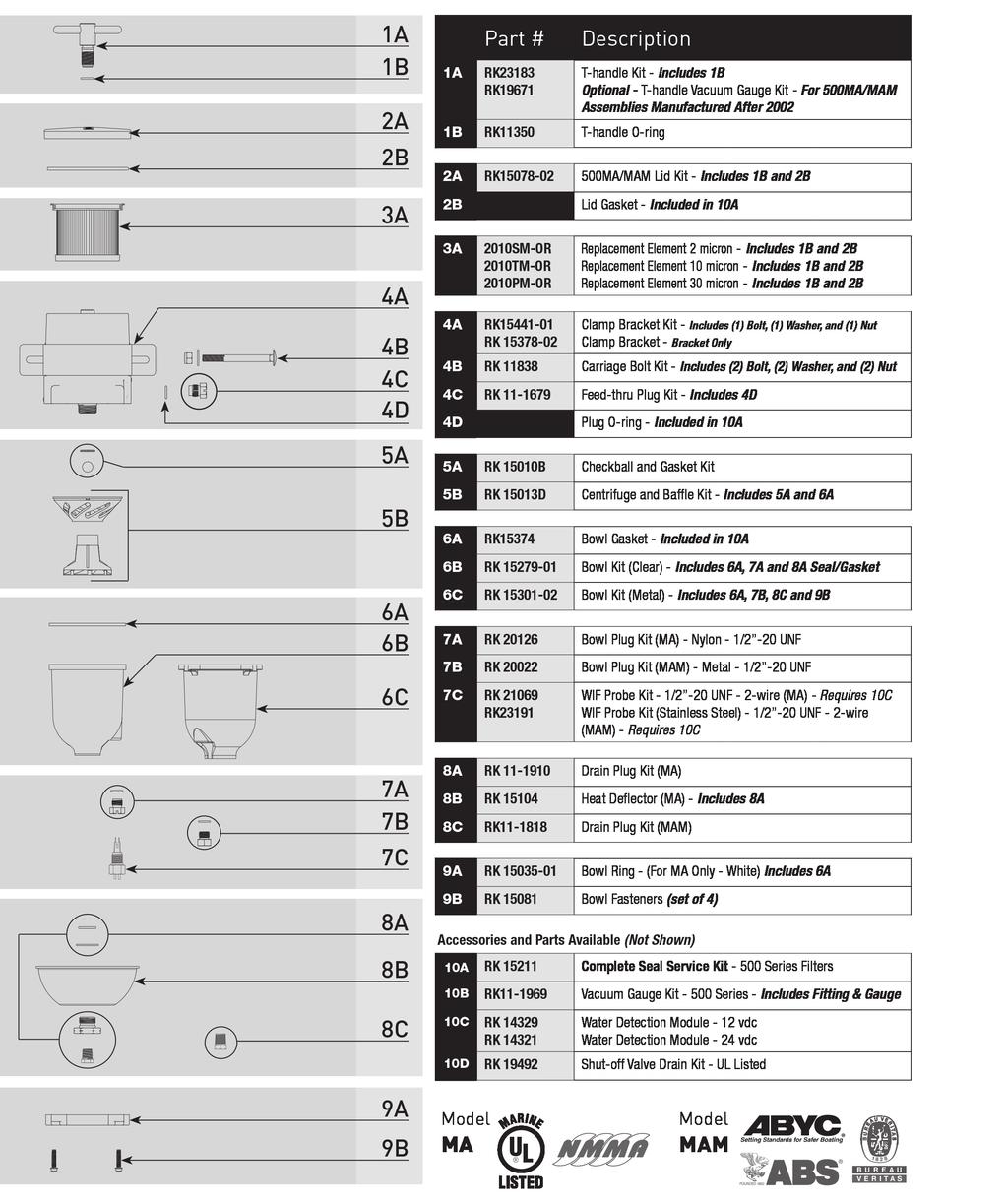
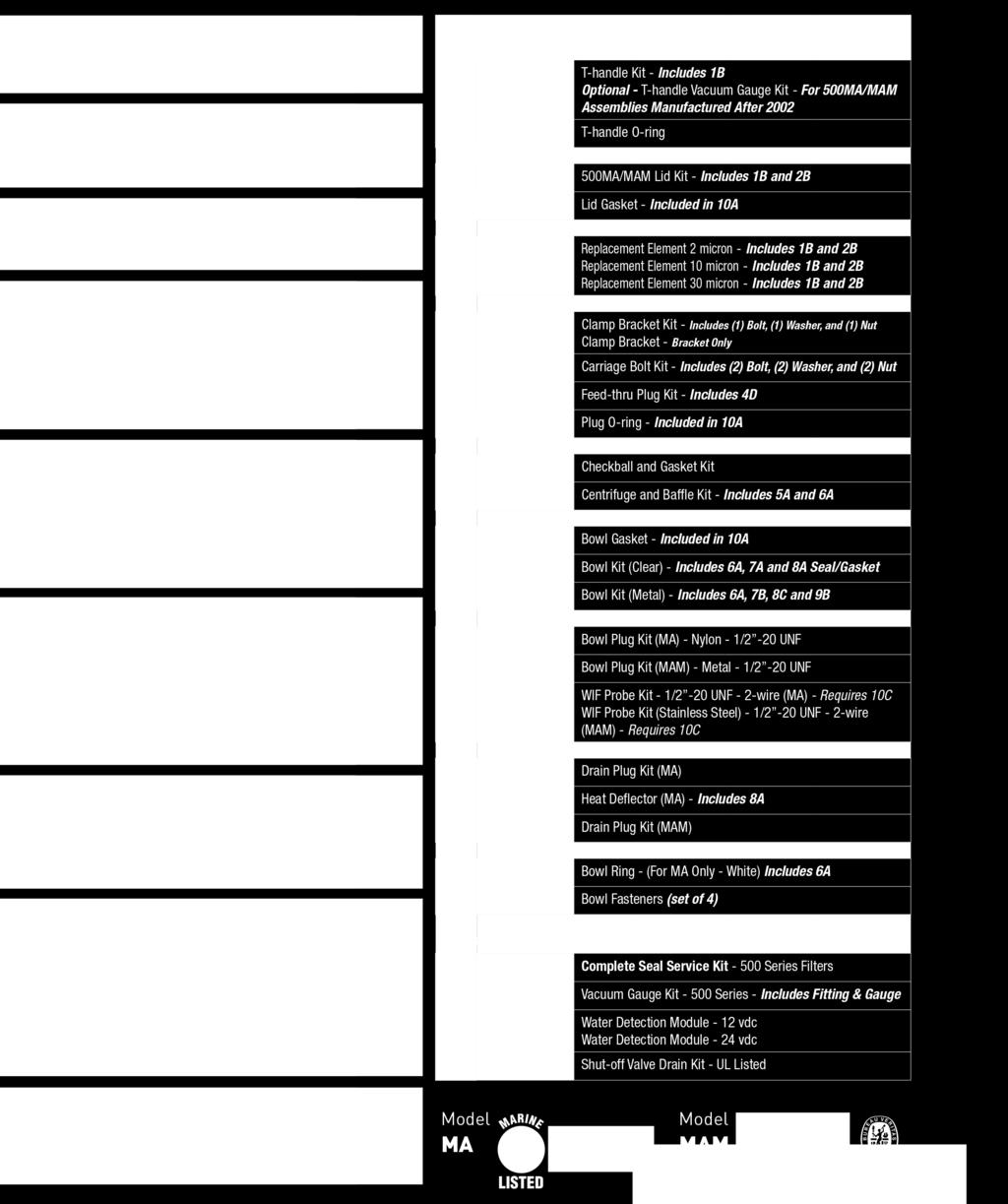
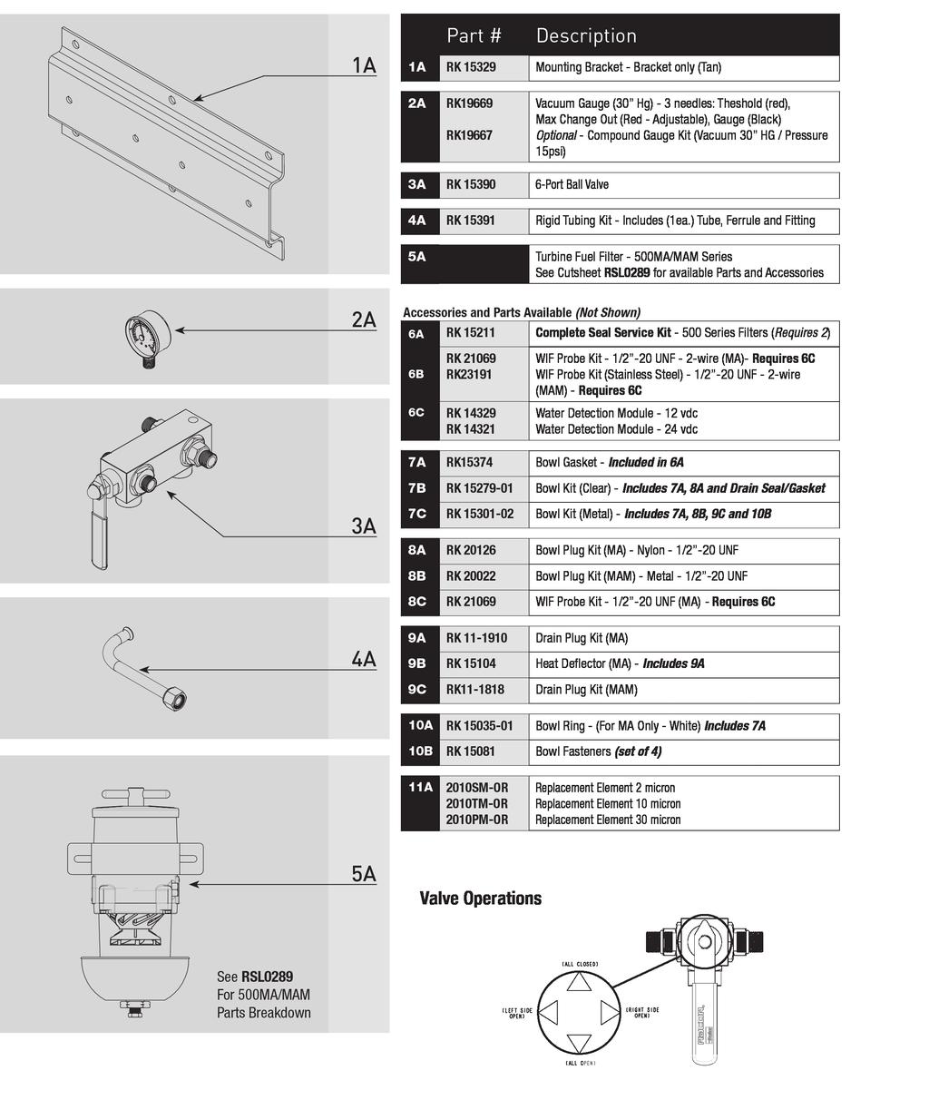
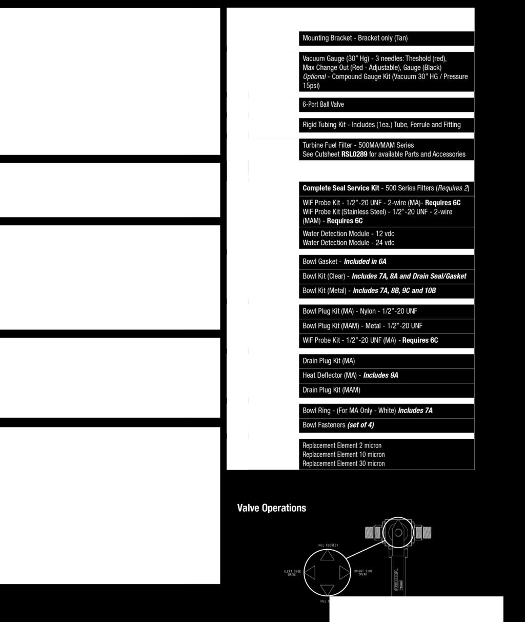
4 Selector Valve The Racor filter assembly allows the isolation of one filter at a time for servicing while engine is running. The handle pointer always indicates which unit is on-line. To take one filter off-line for servicing while engine is running, select the filter to stay on-line, then begin servicing the other unit. CAUTION! The handle can rotate 360, so be very careful to avoid the BOTH OFF position (arrow up) while engine is running. Both On Pointer on handle points down to inlet and outlet ports Left On Pointer on handle points to left unit Right On Pointer on handle points to right unit Both Off Pointer on handle points up/away from inlet and outlet ports Filter Replacement Frequency of filter replacement is determined by contamination level of fuel. Replace filter every 500 hours, every other oil change, when vacuum gauge (optional) reads between 7 to 10 inches of mercury (inhg), if power loss is noticed, or annually, whichever comes first. Note always carry extra replacement filters as one tankful of excessively dirty fuel can plug a filter. Use only genuine Racor Aquabloc replacement filters see Replacement Part list. All Applications: 1. Bypass filter assembly with bypass valves, if applicable. 2. Remove T-handle and lid. 3. Remove filters by holding bail handles and slowly pulling upward with a twisting motion. Dispose properly according to local regulations. 4. Replace old lid gasket and T-handle O-ring with new seals (supplied with new filter). Lubricate both seals with motor oil or diesel fuel before installation. 5. Refer to Priming Instructions, otherwise, fill unit with clean fuel, replace lid and T-handle and tighten snuggly by hand only do not use tools. Note above ground tanks or transfer pump applications may use head pressure to prime filter assembly.

 call Racor Technical Support for assistance: (800) 344-3286 or (209)")
 (two units online) 60 GPH (227 LPH)")
 (below assembly) Replacement Filter (2 micron) (10 micron) (30 micron) 4.")
 11.0 in. (27.9 cm) Width 14.5 in. (36.8 cm) 14.5 in. (36.8 cm) Depth 9.5 in. (24.1 cm) 9.")
 25 PSI (1.7 bar) Clean Pressure Drop 0.7 PSI (0.")
5 Troubleshooting A major cause of power loss or hard starting is result of an air leak (or clogged filter). If your unit will not prime or fails to hold prime, check that drain, bowl and filter are properly tightened. Next, check all fitting connections and ensure fuel lines are not pinched or clogged with contaminants. If problems persist (and filter is new) call Racor Technical Support for assistance: (800) or (209) Specifications 75500MAX 75500MAXM Maximum Flow Rate: (one unit online) (two units online) 60 GPH (227 LPH) 120 GPH (454 LPH) 60 GPH (227 LPH) 120 GPH (454 LPH) Port Size 3/4-16 (SAE J1926) 3/4-16 (SAE J1926) Minimum Service Clearance (above assembly) (below assembly) Replacement Filter (2 micron) (10 micron) (30 micron) 4.0 in. (10.2 cm) 2.0 in. (5.1 cm) 2010SM-OR 2010TM-OR 2010PM-OR 4.0 in. (10.2 cm) 2.0 in. (5.1 cm) 2010SM-OR 2010TM-OR 2010PM-OR Height 11.5 in. (29.2 cm) 11.0 in. (27.9 cm) Width 14.5 in. (36.8 cm) 14.5 in. (36.8 cm) Depth 9.5 in. (24.1 cm) 9.5 in. (24.1 cm) Weight (dry) 17.0 lb (7.7 kg) 18.0 lb (8.2 kg) Max. Working Pressure 25 PSI (1.7 bar) 25 PSI (1.7 bar) Clean Pressure Drop 0.7 PSI (0.048 bar) 0.7 PSI (0.048 bar) Water Removal Efficiency 99% 99% Ambient Temp. Range Max. Fuel Temperature -40 F to +250 F (-40 C to +121 C) 190 F (32 C)
6
7
8 Limited Warranties Statement All products manufactured or distributed by Racor are subject to the following, and only the following, LIMITED EXPRESS WARRANTIES, and no others: For a period of one (1) year from and after the date of purchase of a new Racor product, Racor warrants and guarantees only to the original purchaser-user that such a product shall be free from defects of materials and workmanship in the manufacturing process. The warranty period for pumps and motors is specifically limited to ninety (90) days from date of purchase. A product claimed to be defective must be returned to the place of purchase. Racor, at its sole option, shall replace the defective product with a comparable new product or repair the defective product. This express warranty shall be inapplicable to any product not properly installed and properly used by the purchaser-user or to any product damaged or impaired by external forces. THIS IS THE EXTENT OF WARRANTIES AVAILABLE ON THIS PRODUCT. RACOR SHALL HAVE NO LIABILITY WHATSOEVER FOR CONSEQUENTIAL DAMAGES FLOWING FROM THE USE OF ANY DEFECTIVE PRODUCT OR BY REASON OF THE FAILURE OF ANY PRODUCT. RACOR SPECIFICALLY DISAVOWS ALL OTHER WARRANTIES, EXPRESS OR IMPLIED INCLUDING, WITHOUT LIMITATION, ALL WARRANTIES OF FITNESS FOR A PARTICULAR PURPOSE (EXCEPT FOR THOSE WHICH APPLY TO PRODUCT OR PART THEREOF THAT IS USED OR BOUGHT FOR USE PRIMARILY FOR PERSONAL, FAMILY, OR HOUSEHOLD PURPOSES), WARRANTIES OF DESCRIPTION, WARRANTIES OF MERCHANTABILITY, TRADE USAGE OR WARRANTIES OR TRADE USAGE. Warning Failure or improper selection or improper use of the products and/or systems described herein or related items can cause death, personal injury and property damage. This document and other information from Parker Hannifin Corporation, its subsidiaries and authorized distributors provide product and/or system options for further investigation by users having technical expertise. It is important that you analyze all aspects of your application and review the information concerning the product or system in the current product catalog. Due to the variety of operating conditions and applications for these products or systems, the user, through its own analysis and testing, is solely responsible for making the final selection of the products and systems and assuring that all performance, safety and warning requirements of the applications are met. The products described herein, including with limitation, product features, specifications, designs, availability and pricing, are subject to change by Parker Hannifin Corporation and its subsidiaries at any time without notice. The following statement is required pursuant to proposition 65, applicable in the State of California: This product may contain a chemical known to the State of California to cause cancer or reproductive toxicity. Parker Hannifin Corporation May 2017
Racor 75500FGX Turbine Series fuel
 Installation Instructions 75500FGX Fuel Filter Racor 75500FGX Turbine Series fuel filter/water separator assemblies are designed to be installed on the vacuum side of the fuel transfer pump for best efficiency
320R-RAC Series. Gasoline Fuel Filter/Water Separators. Overview: Contact Information: Product Features: Instruction Part Number Rev.
 30R-RAC Series Gasoline Fuel Filter/Water Separators Instruction Part Number 37 Rev. D Overview: Racor 30R-RAC series filters are designed for high-performance applications, which means your engine will
660R-RAC Series. Gasoline Fuel Filter/Water Separators. Overview: Contact Information: Product Features: Instruction Part Number Rev F
 660R-RAC Series Gasoline Fuel Filter/Water Separators Instruction Part Number 1385 Rev F Overview: Don t be caught in the water without one of these Racor gasoline spin on series filters. These filters
900MA/MAM and 1000MA/MAM (for marine applications)
") 900MA/MAM and 1000MA/MAM (for marine applications) Fuel Filter/Water Separator Instruction Part Number 19526 Rev B Racor Turbine Series fuel filter/ water separator protects the precision components of
900MA/MAM and 1000MA/MAM (for marine applications) Fuel Filter/Water Separator Instruction Part Number 19526 Rev B Racor Turbine Series fuel filter/ water separator protects the precision components of
Product Features: Removes 99% of free water. Available with 2, 10, or 30 micron Aquabloc II media
 120A and 120B Series Fuel Filter/Water Separators Instruction Part Number 10219 Rev B Overview: 120A and 120B fuel filter/water separators are designed to be installed on the suction side of the fuel system
120RMAM Marine Series Fuel Filter/Water Separators
 10RMAM Marine Series Fuel Filter/Water Separators Instruction Part Number 1945 Rev A Overview The 10RMAM fuel filter/water separator features 1/4-18 NPTF inlet and outlet fuel ports and a unitized mounting
Product Features. Easy installation. Pump adds only 3.3 to the overall assembly height. 60 GPH (227 LPH) flow rate while in priming mode.
 flow rate while in priming mode.") Primer Pump Kits RKP1912 (12 vdc) and RKP1924 (24 vdc) Instruction Part Number 14356 Rev C Primer pump kits are an innovative and proprietary system consisting of a prescreen filter, a flow by-pass circuit,
Primer Pump Kits RKP1912 (12 vdc) and RKP1924 (24 vdc) Instruction Part Number 14356 Rev C Primer pump kits are an innovative and proprietary system consisting of a prescreen filter, a flow by-pass circuit,
400 Series Spin-on Fuel Filter/Water Separators
 00 Series Spin-on Fuel Filter/Water Separators Instruction Part Number 09 Rev G 00 Series fuel filter/water separators are designed to handle today s tough fuel filtration problems and can be used anywhere
Marine Fuel Filtration Marine 800 Series
 Racor recyclers offer large diesel engine operators both ease of maintenance and continuous engine operation. Continuous operations include filter changeouts and the draining of accumulated water from
Marine Gasoline Products
 025 -RAC eries Marine Gasoline Products In -line Fuel Filters Being on the water is fun, having water in your fuel is not. More than ever, today s high performance gasoline engines require clean, dry fuel.
Marine Fuel Filtration. Marine Turbine Series. Stage One: Separation. Stage Two: Coalescing. Stage Three: Filtration. And more
 filter assemblies are designed to be installed on the vacuum side of the fuel transfer pump for best efficiency and protect precision engine components from dirt, rust, algae, asphaltines, varnishes, and
All Racor filter materials and seals are compatible with ultra-low sulphur diesel (ULSD) fuel and B2 to B20 Biodiesel. See Racor bulletin 7679.
 fuel and B2 to B20 Biodiesel. See Racor bulletin 7679.") 000MA Water-in-fuel sensor and indicator. MA units have shielded see-thru bowls; MAM bowls are all-metal. UL-listed drain valve and water sensor probe options are available. Turbine Series Electric Primer
000MA Water-in-fuel sensor and indicator. MA units have shielded see-thru bowls; MAM bowls are all-metal. UL-listed drain valve and water sensor probe options are available. Turbine Series Electric Primer
Marine Turbine Series
 1000MA Water-in-fuel sensor and indicator. All Racor filter materials and seals are compatible with ultra-low sulphur diesel (ULSD) fuel and B2 to B20 Biodiesel. See Racor bulletin 7679. The complete Primer
900FH and 1000FH Turbine Series Fuel Filter/Water Separators Installation, Operation, and Service Information
 900FH and 1000FH Turbine eries Fuel Filter/Water eparators Installation, Operation, and ervice Information Overview The 900FH and 1000FH Turbine eries filter assemblies protect precision engine components
Marine Fuel Filtration. Marine FBO. Features:
 The Racor assembly is specifically designed to meet the filtration requirements of today s high pressure common rail diesel injection systems. The unit is used for fuel dispensing pumps or as a primary
Introduction. Marine Turbine Series. Model Illustrations. Special Notes. Specifications 77/1000MA 73/1000MA 75/500MAX 75/900MAX 79/1000MAV 75/1000MAX
 Introduction Model Illustrations 5MA 5MAM 9MA 1MA 7/1MA 77/1MA 75/5MAX Special Notes 75/9MAX 75/1MAX 79/1MAV 1. See--thru bowl MA / MAX / MAV units are approved for Diesel service only. UL Listed, USCG
MARINE. Diesel Fuel/Water Separators. Installation. Operation. Parts. Service Information
 Diesel Fuel/Water Separators stallation Operation Parts Service formation INSTALLATION A. Filter Mounted Above Fuel Storage Tank. Select a location in the fuel line between the fuel tank and the fuel pump,
General The Racor Marine Diesel Spin--on Series feature a variety of compact sizes to fit most installations and cramped engine compartments.
 Selection Selection Information General The Racor Marine Diesel Spin--on Series feature a variety of compact sizes to fit most installations and cramped engine compartments. Mounting Heads: These units
TORK DIESEL FILTER/WATER SEPARATOR
 TORK DIESEL FILTER/WATER SEPARATOR www.smstork.com TECHNICAL SPECIFICATION MODELS T-WPS100 T-WPS230 T-WPS560 T-WPS1120 T-WPS1680 T-WPS2240 In-out Port Flow Rate LPH Horse Power Particle Seperation Dimensions
ACHL Series Pump. Operation and Maintenance Manual Air Driven, Hand Operated High Pressure Liquid Pump
 ACHL Series Pump Operation and Maintenance Manual Air Driven, Hand Operated High Pressure Liquid Pump Catalog: 02-9245ME February 2013 Model # Serial # Drawing # Order # Mfg. Date Table of Contents page
FPS-500. Fuel Polishing System Eliminates Microbial Contamination. Operating Manual
 FPS-500 Fuel Polishing System Eliminates Microbial Contamination Operating Manual Stabilizes Fuel Removes Water & Sludge Prevents Tank Sediments Improves Engine Reliability Optimizes Fuel Quality Optimal
Maintenance Manual. Automated Fuel Maintenance System FTI-5A SINGLE TANK FUEL TECHNOLOGIES INTERNATIONAL
 Maintenance Manual Automated Fuel Maintenance System FTI-5A SINGLE TANK FUEL TECHNOLOGIES INTERNATIONAL 05/01/2016 Rev A Fuel Technologies FTI-5A Single Tank Maintenance Section FTI - Fuel Maintenance
Dual/Triple Manifold Water Filtration Systems Instruction Manual
 3M TM Water Filtration Products Dual/Triple Manifold Water Filtration Systems Instruction Manual High Flow Series Water Filtration Systems Installer: Please leave this manual with owner/operator. 3M Water
Gasoline Fuel Filters. For Marine Applications
 Gasoline Fuel Filters For Marine Applications Complete Protection On The Water Every time you squeeze the trigger, you threaten your engines life. More than ever, today s high-performance gasoline inboard
Dual Flow Manifold Systems Instruction Manual
 3M TM Water Filtration Products Dual Flow Manifold Systems Instruction Manual For DF1XX and DF2XX High Flow Series manifolds and water filtration systems Installer: Please leave this manual with owner/operator.
11101, & INSTALLATION INSTRUCTIONS
 11101, 11108 & 11151 INSTALLATION INSTRUCTIONS WARNING! The fuel system is under pressure. Do not open the fuel system until the pressure has been relieved. Refer to the appropriate vehicle service manual
PARTS AND INSTALLATION MANUAL
 PSP-3240 POLYPROPYLENE SELF-PRIMING 2 CENTRIFUGAL PUMP PARTS AND INSTALLATION MANUAL PSP-3240 Shown with GX-160 Honda CDS-JOHN BLUE COMPANY DIVISION OF ADVANCED SYSTEMS TECHNOLOGY, INC. 165 Electronics
Maintenance Manual. Automated. Fuel Maintenance System FTI-5A. FUEL TECHNOLOGIES INTERNATIONAL LLC
 Maintenance Manual Automated Fuel Maintenance System FTI-5A FUEL TECHNOLOGIES INTERNATIONAL LLC www.fueltechnologiesinternational.com 03/01/2011 - Fuel Technologies FTI-5A Maintenance Section FTI - Fuel
Dual Port Manifold Water Filtration Systems Instruction Manual
 M TM Water Filtration Products Dual Port Manifold Water Filtration Systems Instruction Manual For DP1XX, DP2XX and DPXX High Flow Series Water Filtration Systems Installer: Please leave this manual with
Maintenance Manual WITH ONE SUBMERSIBLE PUMP. Automated Fuel Maintenance System FTI-5A FUEL TECHNOLOGIES INTERNATIONAL LLC
 Maintenance Manual WITH ONE SUBMERSIBLE PUMP Automated Fuel Maintenance System FTI-5A FUEL TECHNOLOGIES INTERNATIONAL LLC Replacement Manuals Available on Website: www.fueltechnologiesinternational.com
BMK-30. Heavy-Duty By-Pass Filtration System Installation and Servicing Instructions
 BMK-30 Heavy-Duty By-Pass Filtration System Installation and Servicing Instructions IMPORTANT NOTICE Read all instructions completely before attempting to install this unit. Improper installation could
High Pressure Gear Pumps & Motors Series PZG Pumps Series MZG Motors
 High Pressure Gear Pumps & Motors Series PZG Pumps Series MZG Motors Bulletin 650-Z1 High Pressure Gear Pumps and Gear Motors for today s demanding mobile and industrial applications. The PZG and MZG Series
DY Series 1-Piece Ball Valves. Catalog 1001C-A. July 2012 欧陆传动
 DY Series 1-Piece Ball Valves Catalog 1001C-A July 2012 欧陆传动 aerospace climate control electromechanical filtration fluid & gas handling hydraulics pneumatics process control sealing & shielding Contents
STC 2W Series Solenoid Valves
 STC 2W160-500 Series Solenoid Valves 2W160-500 Series Solenoid Valve Specifications Valve Model 2W160-3/8 2W160-1/2 2W200-3/4 2W250-1 2W350-1 1/4 2W400-1 1/2 2W500-2 Valve Type Action 2 Way, Normally Closed
AEROMOTIVE Part # INSTALLATION INSTRUCTIONS
 AEROMOTIVE Part # 14102 INSTALLATION INSTRUCTIONS CAUTION: Installation of this product requires detailed knowledge of automotive systems and repair procedures. We recommend that this installation be carried
FPS-500 / FPS 750. Fuel Polishing System. Installation and Operating Manual
 FPS-500 / FPS 750 Fuel Polishing System Eliminates Microbial Contamination Installation and Operating Manual Stabilizes Fuel Removes Water & Sludge Prevents Tank Sediments Improves Engine Reliability Optimizes
AEROMOTIVE Part # Generic Fuel System Kit INSTALLATION INSTRUCTIONS
 AEROMOTIVE Part # 17125 Generic Fuel System Kit INSTALLATION INSTRUCTIONS CAUTION: Installation of this product requires detailed knowledge of automotive systems and repair procedures. We recommend that
STC 2L Series Solenoid Valves
 STC 2L170-500 Series Solenoid Valves 2L170-500 Series Solenoid Valve Specifications Valve Model 2L170-3/8 2L170-1/2 2L170-3/4 2L200-1 2L300-1 1/2 2L500-2 Valve Type Action 2 Way, Normally Closed (NC) Pilot
Stainless Steel Pilot Piston Solenoid Valve 2MS Series for High Temperature & High Pressure
 Stainless Steel Pilot Piston Solenoid Valve 2MS Series for High Temperature & High Pressure S T C TM To Order, Please Specify: 1) Model No., 2) Voltage 2 Way, NC Pilot Piston Stainless Steel Part No. Voltage
18660, 18661, & Stealth Fuel Cell INSTALLATION INSTRUCTIONS
 18660, 18661, 18662 & 18663 Stealth Fuel Cell INSTALLATION INSTRUCTIONS WARNING! The fuel system is under pressure. Do not open the fuel system until the pressure has been relieved. Refer to the appropriate
13101 / / and Installation Instructions
 13101 / 13151-13109 / 13159 and 13114 Installation Instructions WARNING! The fuel system is under pressure. Do not open the fuel system until the pressure has been relieved. Refer to the appropriate vehicle
DIESEL FUEL FILTER/WATER SEPARATORS & Recycler Systems
 DIESEL FUEL FILTER/WATER SEPARATORS & Recycler Systems DAHL DIESEL FUEL FILTER/WATER SEPARATORS REMOVE DIESEL FUEL SYSTEM PROBLEMS ALONG WITH WATER Water and solid contaminants displace the diesel fuel
WARNING User Responsibility
 WARNING User Responsibility FAILURE OR IMPROPER SELECTION OR IMPROPER USE OF THE PRODUCTS DESCRIBED HEREIN OR RELATED ITEMS CAN CAUSE DEATH, PERSONAL INJURY AND PROPERTY DAMAGE. This document and other
INSTRUCTION MANUAL G-Surge Tank #40007, #40008 & #40009
 FiTech Fuel Injection INSTRUCTION MANUAL Tank #40007, #40008 & #40009 Warning: Caution must be observed when installing any product involving fuel system parts or gas tank modifications. Work in a well
AEROMOTIVE Part # and F-Body Fuel System Kit INSTALLATION INSTRUCTIONS
 AEROMOTIVE Part # 17101 and 17102 93-97 F-Body Fuel System Kit INSTALLATION INSTRUCTIONS CAUTION: Installation of this product requires detailed knowledge of automotive systems and repair procedures. We
18324 INSTALLATION INSTRUCTIONS 65 PONTIAC LEMANS
 18324 INSTALLATION INSTRUCTIONS 65 PONTIAC LEMANS The enclosed Aeromotive fuel tank/pump assembly utilizes an o-ring sealed AN-06 style feed, return and vent ports. These ports seal with o-rings; they
RECYCOIL Used Oil Tank
 RECYCOIL Used Oil Tank Owners and Users Manual *Tanks may not be exactly as shown. 198900 Rev. 5 Revised 03-12-13 LIMITED WARRANTY Westeel Division of Vicwest Corporation ( Westeel ) warrants products
11202 INSTALLATION INSTRUCTIONS
 11202 INSTALLATION INSTRUCTIONS WARNING! The fuel system may be under pressure. Do not open the fuel system until any pressure has been relieved. The enclosed Aeromotive fuel pump utilizes an o-ring sealed
AEROMOTIVE Part # Mustang 5.0L Fuel System Kit INSTALLATION INSTRUCTIONS
 AEROMOTIVE Part # 17103 83-93 Mustang 5.0L Fuel System Kit INSTALLATION INSTRUCTIONS CAUTION: Installation of this product requires detailed knowledge of automotive systems and repair procedures. We recommend
INSTRUCTIONS AND SERVICE MANUAL WITH PARTS LIST
 CMP SERIES CPM15-15B (25905F300) CPM15-15B-H/D (25905F301) CPM18-15B (25905F303) CPM18-15B-H/D (25905F304) INDUSTRIAL PUMPS INSTRUCTIONS AND SERVICE MANUAL WITH PARTS LIST NOTE! To the installer: Please
AEROMOTIVE Part # & Mustang Stealth Fuel Tank w/fuel pump INSTALLATION INSTRUCTIONS
 AEROMOTIVE Part # 18685 &18686 86-98.5 Mustang Stealth Fuel Tank w/fuel pump INSTALLATION INSTRUCTIONS CAUTION: Installation of this product requires detailed knowledge of automotive systems and repair
# and # FAST Fuel System Kits
 1 INSTRUCTIONS #307500 and #307501 Fuel System Kits Thank you for choosing products; we are proud to be your manufacturer of choice. Please read this instruction sheet carefully before beginning the installation.
200 & 300 SERIES Diesel Fuel/Water Separators
 200 & 300 SERIES Diesel Fuel/Water Separators Installation Operation Parts Service Information INSTALLATION A. FILTER MOUNTED ABOVE FUEL STORAGE TANK 1. Select a location in the fuel line between the fuel
AEROMOTIVE Part # Fuel System Prime Kit INSTALLATION INSTRUCTIONS
 AEROMOTIVE Part # 17301 Fuel System Prime Kit INSTALLATION INSTRUCTIONS CAUTION: Installation of this product requires detailed knowledge of automotive systems and repair procedures. We recommend that
11104 & Installation Instructions
 11104 & 11110 Installation Instructions WARNING! The fuel system is under pressure. Do not open the fuel system until the pressure has been relieved. Refer to the appropriate vehicle service manual for
STC 2DS Series Anti-Hammering Slow Closing Pilot Solenoid Valves
 STC 2DS500-2000 Series Anti-Hammering Slow Closing Pilot Solenoid Valves 2DS500-2000 Series Solenoid Valve Specifications Valve Model 2DS400F 2DS500F 2DS650F 2DS800F 2DS1000F 2DS1250F 2DS1500F 2DS2000F
Installation, Operating and Maintenance Manual
 . Installation, Operating and Maintenance Manual TK 240 Tank Cleaning and Fuel Restoration System www.dieselfueltech.com Email: vernon@dieselfueltech.com Phone: +61 (0) 419 795 676 1 www.dieselfueltech.com
AEROMOTIVE Part # Generic Fuel System Kit INSTALLATION INSTRUCTIONS
 AEROMOTIVE Part # 17242 Generic Fuel System Kit INSTALLATION INSTRUCTIONS CAUTION: Installation of this product requires detailed knowledge of automotive systems and repair procedures. We recommend that
Scale Feeder Manifold Water Filtration System Instruction Manual
 3M TM Water Filtration Products Scale Feeder Manifold Water Filtration System Instruction Manual For SF1XX High Flow Series Water Filtration Systems Installer: Please leave this manual with owner/operator.
PENBERTHY MODELS GL AND GH GAS OPERATED JET PUMPS INSTALLATION, OPERATION AND MAINTENANCE INSTRUCTIONS
 Before installation, these instructions must be read carefully and understood. PRODUCT WARRANTY Emerson warrants its Penberthy products as designed and manufactured to be free of defects in the material
SNAPP. The One-Piece, High-Performance Snap-In Fuel Filter Water Separator. Next
 SNAPP The One-Piece, High-Performance Snap-In Fuel Filter Water Separator 2 Now, getting the fuel filtration you need is a SNAPP. SNAPP. The fuel filter change that changes everything. The world turns
Motorized Stainless 2-Way Valves
 Installation and Operation Manual Motorized Stainless 2-Way Valves Safety Valve ETV Applications WARNING This Heat-Timer valve is strictly an operating valve; it should never be used as a primary limit
Viscount I Hydraulic Motor and Displacement Pump
 INSTRUCTIONS-PARTS LIST 308 674 INSTRUCTIONS This manual contains important warnings and information. READ AND KEEP FOR REFERENCE. Rev. C Supersedes Rev. B Viscount I Hydraulic Motor and Displacement Pump
AEROMOTIVE Part # Ford 5.0 Liter INSTALLATION INSTRUCTIONS
 AEROMOTIVE Part # 14101 86-98 Ford 5.0 Liter INSTALLATION INSTRUCTIONS CAUTION: Installation of this product requires detailed knowledge of automotive systems and repair procedures. We recommend that this
SC2000 Series Stainless Steel, 500 PSI Check Valves
 Sinclair Collins Stainless Steel, 500 PSI Bulletin SC2000-C/USA Climate & Industrial Controls Features & Specifications Features Simple 3-piece design Piston type stem Investment cast 316 stainless steel
AEROMOTIVE Part # Generic Fuel System Kit INSTALLATION INSTRUCTIONS
 AEROMOTIVE Part # 17126 Generic Fuel System Kit INSTALLATION INSTRUCTIONS CAUTION: Installation of this product requires detailed knowledge of automotive systems and repair procedures. We recommend that
Installation and Maintenance Manual
 Installation and Maintenance Manual Automated Fuel Maintenance System FTI-2.8 FUEL TECHNOLOGIES INTERNATIONAL 01/01/2014 Rev A - Fuel Technologies - FTI-2.8 with ModBus OPERATIONS & MAINTENANCE CONTENTS
Section: B Marine Fuel Filtration
 Section: Marine Fuel Filtration aerospace climate control electromechanical filtration fluid & gas handling hydraulics pneumatics process control sealing & shielding Marine Fuel Filtration Table of Contents
Installation and Startup Manual Hydraulic Pumps Series VP1-095 /-110/ -130
 Visit our homepage for additional support parker.com/pmde Installation and Startup Manual Hydraulic Pumps Series VP1-095 /-110/ -130 Effective: May 01, 2015 Supersedes: January 01, 2013 Important installation
PowerFLO 5800/5900 Series
 PowerFLO 5800/5900 Series 5830/5930: 3.0 GPM 5836/5936: 3.6 GPM Inches (mm) Bypass Models Demand Models Switch 1.87 (47.5) 7.58 (192.5) 7.58 (192.5) 9.08 (230.6) 5840/5940: 4.0 GPM 5850/5950: 5.0 GPM Inches
AEROMOTIVE Part # L Ford F L Ford Expedition L Ford F-250 Super Duty INSTALLATION INSTRUCTIONS
 AEROMOTIVE Part # 14118 97-03 5.4L Ford F-150 97-02 5.4L Ford Expedition 98-03 5.4L Ford F-250 Super Duty INSTALLATION INSTRUCTIONS CAUTION: Installation of this product requires detailed knowledge of
Model 100 Series Kits
 Introductory Installation Information 1. Always install DAHL 100 on the vacuum (suction) side of transfer pump and ahead of any other filter: On domestic vehicles, remove the 3/8 inch I.D. hose from the
AEROMOTIVE Part # & Generic Fuel System Kit INSTALLATION INSTRUCTIONS
 AEROMOTIVE Part # 17135 & 17136 Generic Fuel System Kit INSTALLATION INSTRUCTIONS CAUTION: Installation of this product requires detailed knowledge of automotive systems and repair procedures. We recommend
18318 INSTALLATION INSTRUCTIONS CHEVROLET IMPALA
 18318 INSTALLATION INSTRUCTIONS 65-66 CHEVROLET IMPALA The enclosed Aeromotive fuel tank/pump assembly utilizes an o-ring sealed AN-06 style feed, return and vent ports. These ports seal with o-rings;
AEROMOTIVE Part # A3000 Regulator Assembly INSTALLATION INSTRUCTIONS
 AEROMOTIVE Part # 11217 A3000 Regulator Assembly INSTALLATION INSTRUCTIONS CAUTION: Installation of this product requires detailed knowledge of automotive systems and repair procedures. We recommend that
AEROMOTIVE Part # Subaru STI Fuel Rail Kit INSTALLATION INSTRUCTIONS
 AEROMOTIVE Part # 14137 04-06 Subaru STI Fuel Rail Kit INSTALLATION INSTRUCTIONS CAUTION: Installation of this product requires detailed knowledge of automotive systems and repair procedures. We recommend
AEROMOTIVE Part # Ford 5.4L GT500 Shelby Mustang Fuel Rail Kit INSTALLATION INSTRUCTIONS
 AEROMOTIVE Part # 14145 07 Ford 5.4L GT500 Shelby Mustang Fuel Rail Kit INSTALLATION INSTRUCTIONS CAUTION: Installation of this product requires detailed knowledge of automotive systems and repair procedures.
PowerFLO 7800 Series 12 Volt DC Motor-Driven Diaphragm Pumps
 Installation Operation Repair Parts PowerFLO 7800 Series 12 Volt DC Motor-Driven Diaphragm Pumps Specifications Motor Type: 12 VDC, permanent magnet, totally enclosed, non-ventilated Leads: 14 AWG, 12
Operation and Maintenance Manual
 Operation and Maintenance Manual Piston Actuated Air Operated Valve for c1s/c2s/o1s/o2s model operators 10V SW 10SM 20SM 30VM 40VM 60VM 100VM 150V series valves Parker Autoclave Engineers Instrumentation
AEROMOTIVE Part # Subaru Fuel Rails for Top Feed Injectors WRX & STI INSTALLATION INSTRUCTIONS
 AEROMOTIVE Part # 14135 Subaru Fuel Rails for Top Feed Injectors 02-14 WRX & 07-14 STI INSTALLATION INSTRUCTIONS CAUTION: Installation of this product requires detailed knowledge of automotive systems
3V SERIES SOLENOID VALVE
 3V110-410 SERIES SOLENOID VALVE Valve Model 3V110-1/8 3V210-1/4 3V310-3/8 3V410-1/2 Port & Mounting Action & Motion Operating Pressure Body Ported Air Pilot, Spool Design, Response Time
MGFHVLP. Instructions/Parts. Mini Gravity Feed System E. Part No Includes MGFHVLP Mini Gravity Feed Spray Gun and MGC 125 Gravity Cup.
 Instructions/Parts MGFHVLP Mini Gravity Feed System FOR PRODUCT INFORMATION CALL: 1-800-742-7731 309989E For gravity feed spraying of automotive colors and clears. Ideal for touch-up and detail work. Important
AEROMOTIVE Part # /2 4.6L SOHC Ford Fuel Rail Kit INSTALLATION INSTRUCTIONS
 AEROMOTIVE Part # 14125 96-98 1/2 4.6L SOHC Ford Fuel Rail Kit INSTALLATION INSTRUCTIONS CAUTION: Installation of this product requires detailed knowledge of automotive systems and repair procedures. We
INSTALLATION AND OPERATIONS MANUAL FUEL POLISHING MODULE (FPM)
") INSTALLATION AND OPERATIONS MANUAL FUEL POLISHING MODULE (FPM) Models 60M, 90M, 180M DIESEL ENGINES ONLY Don t Leave Shore Without It. IMPORTANT READ BEFORE INSTALLING THE INSTALLATION AND SETUP SHOULD
INSTALLATION AND OPERATIONS MANUAL FUEL POLISHING MODULE (FPM) Models 60M, 90M, 180M DIESEL ENGINES ONLY Don t Leave Shore Without It. IMPORTANT READ BEFORE INSTALLING THE INSTALLATION AND SETUP SHOULD
Model GP Triplex Ceramic Plunger Pump Operating Instructions/ Manual
 Model GP6145-3100 Triplex Ceramic Plunger Pump Operating Instructions/ Manual Contents: Installation Instructions: page 2 Pump Specifications: page 3 Exploded View: page 4 Parts List / Kits: page 5 Repair
Marine Retail Basics. Product Overview
 Marine Retail Basics Product Overview Diesel Fuel Filter/Water Separator The Racor s fuel filter/water separators feature a variety of compact sizes to fit the most cramped engines. Most units feature
AEROMOTIVE Part # L Ford F L Ford Expedition L Ford F-250 Super Duty INSTALLATION INSTRUCTIONS
 AEROMOTIVE Part # 14118 97-03 5.4L Ford F-150 97-02 5.4L Ford Expedition 98-03 5.4L Ford F-250 Super Duty INSTALLATION INSTRUCTIONS CAUTION: Installation of this product requires detailed knowledge of
Installation, Operation and Maintenance Manual
 IOM-HS-QTColdBevMax Installation, Operation and Maintenance Manual QT TM Cold Bev Max TM Models: QTCLDBMX-1S-.5M, QTCLDBMX-2S-.5M, QTCLDBMX-3S-.5M, QTCLDBMX-4S-.5M, QTCLDBMX-5S-.5M Tested and Certified
SNAPP. The One-Piece, High-Performance Snap-In Fuel Filter Water Separator
 SNAPP The One-Piece, High-Performance Snap-In Fuel Filter Water Separator Now, getting the fuel filtration you need is a SNAPP. SNAPP. The fuel filter change that changes everything. The world turns to
4V130P-430P SERIES AIR PILOT VALVE
 4V130P-430P SERIES AIR PILOT VALVE Valve Model 4V130P-1/8 4V230P-1/4 4V330P-3/8 4V430P-1/2 Port & Mounting Action & Motion Operating Pressure Body Ported Double Solenoid, Spool Design, 3 Position, Pressure
GARDEN HOSE UTILITY PUMP
 GARDEN HOSE UTILITY PUMP MODEL #HPP360, HPP12V, 473707 MODEL #HPP360, 473707 MODEL #HPP12V ATTACH YOUR RECEIPT HERE Purchase Date SAFETY INFORMATION Please read and understand this entire manual before
ACF Operation Manual
 ACF-3000 Operation Manual MAHLE Aftermarket Inc., RTI Division 10 Innovation Drive York, Pennsylvania 17402 USA Phone: 717-840-0678 Toll Free: 800-468-2321 Web-site: www.rtitech.com Manual P/N: 035 81825
Voltmaster Centrifugal Trash Pumps
 Voltmaster Centrifugal Trash Pumps Model TSP2, TSP3 and TSP4 Owner s Manual February 2011 Table of Contents 1 Introduction............................ 1 1.1 Read before using..................... 1 1.2
Pneutronics. Miniature Proportional Valves. Catalog PND-MPV-001/US January 2007
 Pneutronics Miniature Proportional Valves January 2007 Non-Thermally Compensated Proportional Valve HF 200 Miniature Ultra High Flow Proportional Valve HF 200 is a high flow proportional valve that provides
Installation & Service Instructions
 49124597 Revision A August 2015 PacE Flow Controller, Replacement Kit Installation & Service Instructions Save These Instructions Table of contents INTRODUCTION...........................................................................
D Instructions/Parts. Siphon Feed Detail Spray Gun D
 Instructions/Parts D-5-55 Siphon Feed Detail Spray Gun FOR PRODUCT INFORMATION CALL: 1-800-742-7731 309991D Important Safety Instructions Read all warnings and instructions in this manual. Save these instructions.
INSTRUCTION MANUAL # FiTech Hy-Fuel Tight-Fit In-Tank Retrofit Kit
 FiTech Fuel Injection INSTRUCTION MANUAL #40015 - FiTech Hy-Fuel Tight-Fit In-Tank Retrofit Kit NOTE: This Hy-Fuel In-Tank Kit can be used with any EFI system, or with the proper low pressure bypass style
AEROMOTIVE Part # C5 Corvette Fuel Rail / Regulator Kit INSTALLATION INSTRUCTIONS
 AEROMOTIVE Part # 14129 99-04 C5 Corvette Fuel Rail / Regulator Kit INSTALLATION INSTRUCTIONS CAUTION: Installation of this product requires detailed knowledge of automotive systems and repair procedures.
DESCRIPTION MECHANICAL FUEL PUMP FUEL FILTER HIGH PRESSURE (35-90 PSI) HIGH PRESSURE (35-90 PSI) (STEEL/INCLUDED)
 HIGH PRESSURE (35-90 PSI) (STEEL/INCLUDED)") Edelbrock EFI Universal Fuel Sump System - Adjustable Part #36031, 36032, 36033, 36034 INSTALLATION INSTRUCTIONS PLEASE study these instructions carefully before beginning this installation. This installation
Edelbrock EFI Universal Fuel Sump System - Adjustable Part #36031, 36032, 36033, 36034 INSTALLATION INSTRUCTIONS PLEASE study these instructions carefully before beginning this installation. This installation
Operating instructions Form no safety definitions
 Operating instructions Form no. 1000437 safety definitions safety symbols are used to identify any action or lack of action that can cause personal injury. Your reading and understanding of these safety