SUBMERSIBLE ELECTROPUMPS 50 HZ
|
|
|
- Mabel Octavia Harrell
- 5 years ago
- Views:
Transcription


1 L.Nemitsas Ltd - Head Office P.O.Box Limassol, Cyprus Tel: & Fax: L.Nemitsas Ltd - Nicosia Branch F.Tsigaridi 19 Str. 2235, Latsia - Nicosia Tel: Fax: info@nemitsas.eu URL: SUBMERSIBLE ELECTROPUMPS 50 HZ

2 4, 6 & 8 SUBMERSIBLE PUMPS Installation and Operating Instructions
3 Before beginning installation, the following checks should be made. They are all critical for the proper installation of this submersible pump. A. Condition of the well. If the pump is to be installed in a new well, the well should be fully developed and bailed or blown free of cuttings and sand. The stainless steel construction of the submersible makes it resistant to abrasion; however, no pump, made of any material, can forever withstand the destructive wear that occurs when constantly pumping sandy water. If this pump is used to replace an oil-filled submersible or oil-lubricated line-shaft turbine in an existing well, the well must be blown or bailed clear of oil. Determine the maximum depth of the well, and the draw-down level at the pump s maximum capacity. Pump selection and setting depth should be based on this data. The inside diameter of the well casing should be checked to ensure that it is not smaller than the size of the pump and motor. B. Condition of the water. Submersible pumps are designed for pumping clear and cold water that is free of air and gases. Decreased pump performance and life expectancy can occur if the water is not cold and clear or contains air and gasses. Maximum water temperature should not exceed 102 F. Special consideration must be given to the pump and motor if it is to be used to pump water above 102 F. The stainless steel submersible is highly resistant to the normal corrosive environment found in some water wells. If water well tests determine the water has an excessive or unusual corrosive quality, or exceeds 102 F, contact your Nemitsas representative for information concerning specially designed pumps for these applications.
4 C. Installation Depth. A check should be made to ensure that the installation depth of the pump will always be at least (5) five to (10) ten feet below the maximum draw-down level of the well. For flow rates exceeding 100 gpm, refer to performance curves for recommended minimum submergence. The bottom of the motor should never be installed lower than the top of the well screen or within five feet of the well bottom. If the pump is to be installed in a lake, pond, tank or large diameter well, the water velocity passing over the motor must be sufficient to ensure proper motor cooling. D. Electrical Supply. The motor voltage, phase and frequency indicated on the motor nameplate should be checked against the actual electrical supply. The wire cable used between the pump and control box or panel should be approved for submersible pump applications. The conductor may be solid or stranded. The cable may consist of individually insulated conductors twisted together, insulated conductors molded side by side in one flat cable or insulated conductors with a round overall jacket. The conductor insulation should be type RW, RUW, TW, TWU or equivalent and must be suitable for use with submersible pumps. An equivalent Canadian Standards Association certified wire may also be used. See Table D for recommended sizes of cable lengths.

5 A good cable splice is critical to proper operation of the submersible pump and must be done with extreme care. If the splice is carefully made, it will work as well as any other portion of the cable, and will be completely watertight. Grundfos recommends using a heat shrink splice kit. The splice should be made in accordance with the kit manufacture s instructions. Typically a heat shrink splice can be made as follows: 1. Examine the motor cable and the drop cable carefully for damage. 2. Cut the motor leads off in a staggered manner. Cut the ends of the drop cable so that the ends match up with the motor leads (See Figure 4-A). On single-phase motors, be sure to match the colors. 3. Strip back and trim off 1/2 inch of insulation from each lead, making sure to scrape the wire bare to obtain a good connection. Be careful not to damage the copper conductor when stripping off the insulation. 4. Slide the heat shrink tubing on to each lead. Insert a properly sized Sta-kon type connector on each lead, making sure that lead colors are matched. Using a Sta-kon crimping pliers, indent the lugs (Figure 4-B). Be sure to squeeze hard on the pliers, particularly when using large cable. 5. Center the heat shrink tubing over the connector. Using a propane torch, lighter, or electric heat gun, uniformly heat the tubing starting first in the center working towards the ends (Figure 4-C). 6. Continue to apply the heat to the tubing using care not to let the flame directly contact the tubing. When the tubing shrinks and the sealant flows from the ends of the tubing, the splice is complete (Figure 4-D).
6 Installation. Do not connect the first plastic or flexible riser section directly to the pump. Always attached a metallic nipple or adapter into the discharge chamber of the pump. When tightened, the threaded end of the nipple or adapter must not come in contact with the check valve retainer in the discharge chamber of the pump. The drop cable should be secured to the riser pipe at frequent intervals to prevent sagging, looping and possible cable damage. Nylon cable clips or waterproof tape may be used. The cable splice should be protected by securing it with clips or tape just above each joint. IMPORTANT Plastic and flexible pipe tend to stretch under load. This stretching must be taken into account when securing the cable to the riser pipe. Leave 3 to 4 inches of slack between clips or taped points to allow for this stretching. This tendency for plastic and flexible pipe to stretch will also affect the calculation of the pump setting depth. As a general rule, you can estimate that plastic pipe will stretch to approximately 2% of its length. For example, if you installed 200 feet of plastic riser pipe, the pump may actually be down 204 feet. If the depth setting is critical, check with the manufacturer of the pipe to determine who to compensate for pipe stretch. When plastic riser pipe is used, it is recommended that a safety cable be attached to the pump to lower and raise it. Check valves: A check valve should always be installed at the surface of the well. In addition, for installations deeper than 200 feet, check valves should be installed at no more than 200 foot intervals. Protect the well from contamination: To protect against surface water entering the well and contaminating the water source, the well should be finished off above grade, and a locally approved well seal or pitless adapter unit utilized.
7 Electrical. WARNING: To reduce the risk of electrical shock during operation of this pump requires the provision of acceptable grounding. If the means of connection to the supply connected box is other than grounded metal conduit, ground the pump back to the service by connecting a copper conductor, at least the size of the circuit supplying the pump, to the grounding screw provided within the wiring compartment. All electrical work should be performed by a qualified electrician in accordance with the latest edition of the National Electrical Code, local codes and regulations. Verification of the electrical supply should be made to ensure the voltage, phase and frequency match that of the motor. Motor voltage, phase, frequency and fullload current information can be found on the nameplate attached to the motor. If voltage variations are larger than ± 10%, do not operate the pump. Direct on-line starting is used due to the extremely fast run-up time of the motor (0.1 second maximum), and the low moment of inertia of the pump and motor. Direct on-line starting current (locked rotor amp) is between 4 and 6.5 times the full-load current. If direct on-line starting is not acceptable and reduced starting current is required, an autotransformer or resistant starters should be used for 5 to 30 HP motors (depending on cable length). For motors over 30 HP, use autotransformer starters. Engine-Driven Generators If the submersible pump is going to be operated using an engine driven generator, we suggest the manufacturer of the generator be contracted to ensure the proper generator is selected and used. See Table B for generator sizing guide.

 current.")
8 Control Box/Panel Wiring 1. Single-Phase Motors: Single-phase motors must be connected as indicated in the motor control box. A typical single-phase wiring diagram using a control box is shown 2. Three-Phase Motors: Three-phase motors must be used with the proper size and type of motor starter to ensure the motor is protected against damage from low voltage, phase failure, current unbalance and overload current. A properly sized starter with ambient-compensated extra quick-trip overloads must be used to give the best possible motor winding protection. Each of the three motor legs must be protected with overloads. The thermal overloads must trip in less than 10 seconds at locked rotor (starting) current. A three-phase motor wiring diagram is illustrated below Pumps should NEVER be started to check rotation unless the pump is totally submerged. Severe damage may be caused to the pump and motor if they are run dry.
9 Control Box/Panel Grounding The control box or panel shall be permanently grounded in accordance with the National Electrical Code and local codes or regulations. The ground wire should be a bare copper conductor at least the same size as the drop cable wire size. The ground wire should be run as short a distance as possible and be securely fastened to a true grounding point. True grounding points are considered to be: a grounding rod driven into the water strata, steel well casing submerged into the water lower than the pump setting level, and steel discharge pipes without insulating couplings. If plastic discharge pipe and well casing are used or if a grounding wire is required by local codes, a properly sized bare copper wire should be connected to a stud on the motor and run to the control panel. Do not ground to a gas supply line. Connect the grounding wire to the ground point first and then to the terminal in the control box or panel. Start-Up After the pump has been set into the well and the wiring connections have been made, the following procedures should be performed: A. Attach a temporary horizontal length of pipe with installed gate valve to the riser pipe. B. Adjust the gate valve one-third of the way open. C. On three-phase units, check direction of rotation and current unbalance according to the instructions below. For single-phase units proceed directly to Developing the Well. D. Under no circumstances should the pump be operated for any prolonged period of time with the discharge valve closed. This can result in motor and pump damage due to overheating. A properly sized relief valve should be installed at the well head to prevent the pump from running against a closed valve. Three-Phase Motors 1. Check the direction of rotation Three-phase motors can run in either direction depending on how they are connected to the power supply. When the three cable leads are first connected to the power supply, there is a 50% chance that the motor will run in the proper direction. To make sure the motor is running in the proper direction, carefully follow the procedures below: A. Start the pump and check the water quantity and pressure developed. B. Stop the pump and interchange any two leads. C. Start the pump and again check the water quantity and pressure. D. Compare the results observed. The wire connection which gave the highest pressure and largest water quantity is the correct connection.
10 2. Check for current unbalance Current unbalance causes the motor to have reduced starting torque, overload tripping, excessive vibration and poor performance which can result in early motor failure. It is very important that current unbalance be checked in all threephase systems. Current unbalance between the legs should not exceed 5% under normal operating conditions. The supply power service should be verified to see if it is a two or three transformer system. If two transformers are present, the system is an open delta or wye. If three transformers are present, the system is true three-phase. Make sure the transformer rating in kilovolt amps (KVA) is sufficient for the motor load. The percentage of current unbalance can be calculated by using the following formulas and procedures: To determine the percentage of current unbalance: A. Measure and record current readings in amps for each leg (hookup 1). Disconnect power. B. Shift or roll the motor leads from left to right so the drop cable lead that was on terminal 1 is now on 2, lead on 2 is now on 3, and lead on 3 is now on 1 (hookup 2). Rolling the motor leads in this manner will not reverse the motor rotation. Start the pump, measure and record current reading on each leg. Disconnect power. C. Again shift drop cable leads from left to right so the lead on terminal 1 goes to 2, 2 to 3 and 3 to 1 (hookup 3). Start pump, measure and record current reading on each leg. Disconnect power. D. Add the values for each hookup. E. Divide the total by 3 to obtain the average. F. Compare each single leg reading from the average to obtain the greatest amp difference from the average. G. Divide this difference by the average to obtain the percentage of unbalance. Use the wiring hookup which provides the lowest percentage of unbalance.
11 Developing the Well After proper rotation and current unbalance have been checked, start the pump and let it operate until the water runs clear of sand, silt and other impurities. Slowly open the valve in small increments as the water clears until the desired flow rate is reached. Do not operate the pump beyond its maximum flow rating. The pump should not be stopped until the water runs clear. If the water is clean and clear when the pump is first started, the valve should still be slowly opened until the desired flow rate is reached. As the valve is being opened, the drawdown should be checked to ensure the pump is always submerged. The dynamic water level should always be more than 3 feet above the inlet strainer of the pump. Disconnect the temporary piping arrangements and complete the final piping connections. Under no circumstances should the pump be operated for any prolonged period of time with the discharge valve closed. This can result in motor and pump damage due to overheating. A properly sized relief valve should be installed at the well head to prevent the pump from running against a closed valve. Start the pump and test the system. Check and record the voltage and current draw on each motor lead. Operation 1. The pump and system should be periodically checked for water quantity, pressure, drawdown, periods of cycling and operation of controls.
12 Preliminary Tests

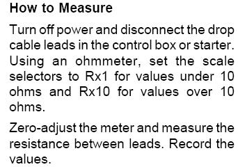
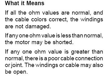
13 Total Resistance of Drop Cable (OHMS) The values shown in this table are for copper conductors. Values are for the total resistance of drop cable from the control box to the motor and back. To determine the resistance: 1. Disconnect the drop cable leads from the control box or panel. 2. Record the size and length of drop cable. 3. Determine the cable resistance from the table. 4. Add drop cable resistance to motor resistance. 5. Measure the resistance between each drop cable lead using an ohmmeter. Meter should be set on Rx1 and zero-balanced for this measurement. 6. The measured values should be approximately equal to the calculated values.
14 Troubleshooting Tips - Submersible Pumps Fuse overload or circuit breaker trips when motor is started CAUSE OF TROUBLE HOW TO CHECK HOW TO CORRECT Check the line voltage terminals in the 1. Incorrect line voltage control box (or connection box) with a If the voltage is incorrect, contact the voltmeter. Make sure the voltage is power company to have it corrected. within the min/max range prescribed by the manufacturer. 2. Defective control box: a. Defective wiring Check all motor and power-line wiring in the control box, following the wiring diagram inside the box. See that all connections are tight and no short circuits exist due to worn insulation, crossed wires, etc. b. Incorrect components Check all control box components to see that they are the type and size specified for the pump in the manufacturer's literature. In previous service work the wrong components may have been installed. Rewire any incorrect circuits. Tighten loose connections. Replace worn wires. Replace any incorrect component with the size and type recommended by the manufacturer. c. Defective starting capacitor (skip for 2-wire models) d. Defective relay (skip for 2-wire models) Using an ohmmeter, X1000 scale, determine the resistance across the disconnected starting capacitor. When contact is made, the ohmmeter needle should jump toward 0, and then drift back slowly towards infinity. No movement indicates an open capacitor, low resistance means the capacitor is shorted. Using an ohmmeter, check the relay coil and contacts. Their resistance should be as shown in the manufacturer's literature. 3. Incorrectly wired pressure switch Check the wiring at the pressure switch Replace defective starting capacitor If coil resistance is incorrect or the contacts are defective, replace the relay. Make sure all line, load and ground connections in the switch match the diagram. 4. Defective motor winding or cable: a. Shortened or open motor winding Check the resistance of the motor winding by using an ohmmeter on the proper terminals in the control box (see manufacturer's wiring diagram). The resistance should match the ohms specified in the data sheet. If it's too low the motor winding may be shorted. If the ohmmeter needle doesn't move, indicating high or infinite resistance, there is an open If the motor winding is defective - shorted or open, the pump must be pulled and the motor should be repaired.
15 b. Grounded cable or winding circuit in the motor winding or cable. Ground one lead of the ohmmeter onto the drop pipe or well casing, then Pull the pump and inspect the cable for touch the other lead to each motor wire damage. Replace damaged cable. If terminal. If the ohmmeter moves cable checks OK, the motor winding is appreciably when this is done, there is grounded. a ground in either the cable or the motor winding. 5. Pump locked Check the line amps before the trip. If amps are twice normal, or higher, the pump is probably locked. Pull pump, disassemble from motor and check which one is locked. Replace one or both if defective. Pump operates but delivers too little or no water CAUSE OF TROUBLE HOW TO CHECK HOW TO CORRECT 1. Pump may be air locked Stop and start the pump several times, waiting about one minute between If this test fails to correct the trouble cycles. If the pump resumes it's normal proceed as below. delivery, air lock was the trouble. 2. Water level in the well is too low Well production may be too low for the pump capacity. Restrict the low of pump output, then wait for the well to recover, and start pump. 3. Discharge line check valve installed backwards. Examine check valve on the discharge line to make sure that the arrow indicating direction of flow points in the right direction. 4. Leak in drop pipe Raise the pipe and examine for leaks. 5. Pump check valve jammed by drop pipe 6. Pump intake screen blocked 7. Pump parts are worn 8. Motor shaft uncoupled When pump is pulled after completing Step 4 above, examine connection of drop pipe to pump outlet. If the threaded section of drop pipe has been screwed in too far, it may be jamming the pump's check valve in the closed position. The intake screen on the pump may be blocked by sand or mud. Examine the screen. Abrasives in the water may result in excessive wear on the impeller, casing and other close-clearance parts. Before pulling the pump, reduce setting on the pressure switch to see if the pump shuts off. If it does, worn parts are probably at fault. Coupling between motor and pump shaft may have worn out or worked loose. Inspect for this after pulling the pump and looking for worn components, as in Step 7 above. If partial restriction corrects trouble, leave valve or cock at the restricted setting. Otherwise lower pump in well if depth is sufficient. Do not lower if sand clogging might occur. Reverse the valve if necessary. Replace the damaged section of drop pipe. Unscrew the drop pipe and cut off the portion of threads. Clean the screen and when reinstalling the pump, make sure it is located several feet above the well bottom - preferably 10 feet or more. Pull the pump and replace the worn components. Tighten all connections, setscrews, etc. Replace parts if worn out.
16 Pump starts too frequently CAUSE OF TROUBLE HOW TO CHECK HOW TO CORRECT 1. Pressure switch defective or out of adjustment Check the setting on the pressure switch and examine for defects. Adjust the pressure setting or replace switch. For discharge or bladder captive air 2. Leak in pressure tank above water tanks, drain the tank and check the precharge pressure. It should be equal to level or 2 psig below pump cut-in pressure. If lower, check welds, braze joints, Replace tank mechanical joints and valve core with a soap solution. DO NOT ATTEMPT TO REPAIR BY WELDING. 3. Leak in plumbing system Examine the service line to the house and distribution branches for leaks. Repair leaks 4. Discharge line check valve leaking Remove and examine. Replace if defective 5. Air volume control plugged Remove and inspect the air volume control. Clean or replace 6. Snifter valve plugged Remove and inspect the snifter valve. Clean or replace 7. Captive air tank has lost charge Check tank. Recharge or replace tank Fuse, overload or circuit breaker trips when pump motor is running CAUSE OF TROUBLE HOW TO CHECK HOW TO CORRECT 1. Incorrect voltage Check the line voltage terminals in the 2. Overheated control or starter 3. Defective control box components (skip this for 2 wire models) control box or connection box in the case of 2 wire models, with a voltmeter. Make sure the voltage is within the min-max range prescribed by the manufacturer. If sunlight or other sources of heat makes the box too hot, overload may trip and fuses may blow. If the box is hot to the touch, this may be the problem. Using an ohmmeter, X1000 scale, determine the resistance across the disconnected running capacitor. When contact is made the ohmmeter needle should jump toward 0, and then drift back towards infinity. No movement indicates an open capacitor; low resistance means the capacitor is shortened. Using an ohmmeter, check the relay coil, its resistance should be shown in the manufacturer's literature. Check amps in red motor lead with the motor running. If amps are much higher than the manufacturer specifies, the start relay contacts are failing to open. If amps are lower, the run capacitor is defective or the motor is overloaded. If the voltage is incorrect, contact the power company for service. Ventilate or shade the box, or remove it from the source of heat. Replace defective components
17 4. Defective motor winding or cable 5. Pump is overloading Check resistance of the motor winding by using an ohmmeter on the proper terminals in the control box. See the manufacturer's wiring diagram. The resistance should match the ohms specified in the manufacturer's data sheet. If too low the motor winding may be shorted. If the ohmmeter needle doesn't move, indicating high or infinite resistance, there is an open circuit in the motor winding. Ground one lead of the ohmmeter onto the drop line or well casing, then touch the other lead to each motor wire terminal. If the ohmmeter needle moves appreciably when this is done, there is a ground in either the cable or the motor winding. If the fuses blow or overloads trip while the well pump is operating, check line amps. If more than 5% above the manufacturer's nameplate value, the pump is overloading, which indicates a defective well pump and / or motor. If neither cable or winding is defective, shorted, grounded or open, the well pump must be pulled and serviced. Pull pump, disassemble from motor and replace one or both if defective. Pump won't shut off CAUSE OF TROUBLE HOW TO CHECK HOW TO CORRECT 1. Defective pressure switch Check the pressure switch to insure contacts are open at the correct pressure. Adjust or replace switch 2. Water level in the well is too low Well production in the well may be too If partial restriction corrects the trouble low for the pump capacity. Restrict leave the cock or valve at the restricted the flow of pump output, wait for the well to recover and then try starting the pump again. setting. Otherwise lower the pump into the well if depth is sufficient. Do not lower if sand clogging might occur. 3. Leak in drop line Replace the damaged section of the drop Raise the pipe and examine it for leaks. pipe. 4. Submersible pump parts are worn The presence of abrasives in the water may result in excessive wear on the impeller, casing and other closeclearance parts. Before pulling the pump, reduce setting on the pressure switch to see if the pump shuts off. If it does, worn parts are probably at fault. Pull the submersible pump and replace worn components.
18 Motor does not start, but fuses don't blow CAUSE OF TROUBLE HOW TO CHECK HOW TO CORRECT Check overloads and circuit breaker to 1. Overload protection is tripped see if they are operable. Check power supply to the control box 2. No power (or overload protection box), by placing a voltmeter across the incoming power lines. Voltage should approximate nominal line voltage. 3. Defective pressure switch Check whether contacts are closed and the same voltage is present between load terminals as line terminals. 4. Defective control box Reset overloads or circuit breaker If no power is reaching the box, contact the power company for service. If the line voltage is not on the line terminals, replace the switch. Examine the winding in the control box to make sure all the contacts are tight. With a voltmeter check voltage at the line and motor terminals. If no voltage is shown at terminals, wiring is Correct faulty wiring or tighten loose defective from pressure switch or in contacts. You may also try cleaning the the control box. With a voltmeter, contacts or replace the switch. check voltage across the pressure switch while the switch is closed. If the voltage drop is equal to the line voltage, the switch is not making contact.
Redi-Flo4. Stainless Steel Submersible Pumps for Environmental Applications GRUNDFOS INSTRUCTIONS. US Installation and operating instructions
 GRUNDFOS INSTRUCTIONS Redi-Flo4 Stainless Steel Submersible Pumps for Environmental Applications US Installation and operating instructions Please leave these instructions with the pump for future reference.
Installation & Operating Manual
 Installation & Operating Manual 6 WS Series Submersible Turbine Pumps Congratulations On Your Choice In Purchasing This Webtrol Pump 6/11 Edition Its Quality is unsurpassed in material and workmanship
2015 EDITION SUBMERSIBLE MOTORS AIM MANUAL. APPLICATION INSTALLATION MAINTENANCE 60 Hz, Single-Phase and Three-Phase Motors. franklinwater.
 0 EDITION AIM MANUAL SUBMERSIBLE MORS APPLICATION INSTALLATION 60 Hz, Single-Phase and Three-Phase Motors franklinwater.com All Motors System Troubleshooting Motor Does Not Start A. No power or incorrect
OWNERS GUIDE TO INSTALLATION AND OPERATION OF 1/2-5 HP, 5, 7, 10, 15, 19 & 27 GPM 4 SUBMERSIBLE PUMPS
 FW0080 0511 Supersedes 0610 OWNERS GUIDE TO INSTALLATION AND OPERATION OF 1/2-5 HP, 5, 7, 10, 15, 19 & 27 GPM 4 SUBMERSIBLE PUMPS IL0632 WARNING IMPORTANT SAFETY INSTRUCTIONS RULES FOR SAFE INSTALLATION
SS/SSH Submersible Pump. Owner s Manual
 Est. 1985 www.aquascience.net SS/SSH Submersible Pump Owner s Manual 4 SUBMERSIBLE PUMP INSTALLATION INSTRUCTIONS IMPORTANT: Read this manual carefully before installing or operating the pump. Review instructions
6TSP Series Radial Flow
 OWNER S MANUAL Submersible Turbine Pumps 293 Wright Street, Delavan, WI 53115 Phone: 888-237-5353 Fax: 800-321-8793 Web Site: berkeleypumps.com 6TSP Series Radial Flow Installation/Operation/Parts For
SUBMERSIBLE PUMPS
 motralec rue Lavoisier. ZA Lavoisier. 5223 HERBLAY CEDEX Tel. : 1.3.7.65. / Fax. : 1.3.7.68 Demande de prix / e-mail : service-commercial@motralec.com www.motralec.com SUBMERSIBLE PUMPS - 6-8 INSTALLATION,
SP4 4-Inch Stainless Steel Sub mers ible Pumps
 GRUNDFOS INSTRUCTIONS SP4 4-Inch Stainless Steel Sub mers ible Pumps US Installation and operating instructions WATER QUALITY DRINKING WATER SYSTEM COMPONENTS ANSI/NSF 61 65 GM 30 C/86 F PUMP END ONLY
2 Wire Plus Ground 3 Wire Plus Ground IL0655
 4 INCH SUBMERSIBLE WELL PUMP 2 & 3 Wire 2 Wire Plus Ground 3 Wire Plus Ground Español p. 21 For installation videos and other information, scan with your smart phone. Or, visit: starwatersystems.com and
JET PUMP INSTALLATION MANUAL. motralec SHALLOW WELL JET PUMPS
 motralec 4 rue Lavoisier. ZA Lavoisier. 95223 HERBLAY CEDEX Tel. : 01.39.97.65.10 / Fax. : 01.39.97.68.48 Demande de prix / e-mail : service-commercial@motralec.com www.motralec.com JET PUMP INSTALLATION
GRUNDFOS INSTRUCTIONS SQ, SQE. Installation and operating instructions
 GRUNDFOS INSTRUCTIONS SQ, SQE Installation and operating instructions LIMITED WARRANTY Products manufactured by GRUNDFOS PUMPS CORPORATION (Grundfos) are warranted to the original user only to be free
4" ENVIRONMENTAL E-SERIES PUMPS OWNER'S MANUAL. DANGER warns about hazards that will cause. WARNING warns about hazards that can cause
 4" ENVIRONMENTAL E-SERIES PUMPS OWNER'S MANUAL BEFORE INSTALLING PUMP, BE SURE TO READ THIS OWNER S MANUAL CAREFULLY. CAUTION Fill pump with water before starting or pump will be damaged. The motor on
VERTICAL MULTI-STAGES CENTRIFUGAL PUMPS
 Installation and Operating Instructions VERTICAL MULTI-STAGES CENTRIFUGAL PUMPS Models 1, 3, 5, 10, 15, 20, 32, 45, 64, 90, 120, 150 1. Model numbering and nameplate format 1.1 Model numbering Example:
HALLMARK INDUSTRIES INC. Deep Well Submersible Pumps Operating & Installation Instructions
 Deep Well Submersible Pumps Operating & Installation Instructions WARNING: Read the user s manual thoroughly before installing the pump! A 115V pump is for 115V (or 110V) power! A 230V pump is for 230V
OWNERS GUIDE TO INSTALLATION AND OPERATION GPM and GPM GPM SUBMERSIBLE PUMPS
 OWNERS GUIDE TO INSTALLATION AND OPERATION 4 3-8 GPM and 6 0-20 GPM 8 32-400 GPM SUBMERSIBLE PUMPS WARNING IMPORTANT SAFETY INSTRUCTIONS RULES FOR SAFE INSTALLATION AND OPERATION 1. Read these warnings
PWP - PWS Submersible Pumps INSTALLATION AND OPERATING INSTRUCTIONS INSTALLATION RECORD
 PWP - PWS 4-6 - 8 Submersible Pumps INSTALLATION AND OPERATING INSTRUCTIONS INSTALLATION RECORD Date of Installation: Model Number: Serial Number: Depth of the Well: Depth of Water: Pump Setting: Wire
VERTICAL MULTI-STAGE CENTRIFUGAL PUMPS
 Installation and Operating Instructions VERTICAL MULTI-STAGE CENTRIFUGAL PUMPS Models 1, 3, 5, 10, 15, 20, 32, 45, 64, 90 1. Model numbering and nameplate format 1.1 Model numbering Example: SBI / SBN
Installation, Operation and Maintenance Manual Stancor SSD & SL Series Pumps
 Installation, Operation and Maintenance Manual Stancor SSD & SL Series Pumps EI-700-008 Rev -- Table of Contents Safety Guidelines 3 Caution 4 Wiring 4 Maintenance 4 Nameplate format 4 Prior to Operation
Installation & Operating Manual
 Installation & Operating Manual VN Series Non-Clog Pumps Congratulations On Your Choice In Purchasing This Webtrol Pump 10/15 Edition Its Quality is unsurpassed in material and workmanship and has been
SDS SERIES DC SUBMERISIBLE PUMPS
 SDS SERIES DC SUBMERISIBLE PUMPS INSTALLATION MANUAL Kyocera Solar, Inc. / SOLARJACK, 7812 E. Acoma Drive, Scottsdale, AZ 85260 Telephone (800) 223-9580 FAX (480) 483-6431 E-mail info@kyocerasolar.com
Material required for drilled well application (indoor use only)
") SAFETY INSTRUCTIONS: This fine pump that you have just purchased is designed from the latest in material and workmanship. Before installation and operation, we recommend the following procedures: A B C
SAFETY INSTRUCTIONS: This fine pump that you have just purchased is designed from the latest in material and workmanship. Before installation and operation, we recommend the following procedures: A B C
TABLE OF CONTENTS. Pump Selection General Safety Electrical Installation Troubleshooting Repair Parts...
 Owner s Manual 4 Submersible Pumps Two & Three Wire, 1/2 through 1-1/2 HP TABLE OF CONTENTS Pump Selection................. 2-3 General Safety.................... 4 Electrical....................... 5-6
2-Wire Deep Well Submersible Pump
 2-Wire Deep Well Submersible Pump Owner s Manual WARNING: Read carefully and understand all ASSEMBLY AND OPERATION INSTRUCTIONS before operating. Failure to follow the safety rules and other basic safety
 Motor Trouble-Shooting Chart Caution:. Disconnect power to the motor before performing service or maintenance.. Discharge all capacitors before servicing motor.. Always keep hands and clothing away from
Submersible Tank Pump
 Submersible Tank Pump Applications: Silent household pressure systems, garden irrigation, or water transfer. Performance Outline Pump Features High efficiency moulded impellers Stainless steel construction,
Commander Pro 100 SUBMERSIBLE SYSTEM Installation, Operation and Trouble-Shooting Manual
 Commander Pro 100 SUBMERSIBLE SYSTEM Installation, Operation and Trouble-Shooting Manual FW1206 0608 Supersedes NEW Owner Information System Model Number Pump Model / Date Code Pump Serial Number (Silver
L-SERIES PUMPS. Operating Manual. Includes Pumps: L-305 L PONDS
 L-SERIES PUMPS Operating Manual Includes Pumps: L-305 L-310 1-877-80-PONDS www.atlanticwatergardens.com Introduction Thank you for selecting the TidalWave L-305/L-310 series pumps. Before using this pump
Model 6TS Submersible Turbine
 Owner s/operator s Manual Model 6TS Submersible Turbine INSTALLATION / OPERATION MAINTENANCE This pump should be serviced by authorized personnel only. For more information, please call Berkeley Pumps
SUBMERSIBLE PUMP HSE RANGE
 SUBMERSIBLE PUMP HSE RANGE OPERATION & MAINTENANCE INSTRUCTIONS 0806 SPECIFICATIONS Model No. HSE120* HSE200 HSE300*/ HSE360*/ HSEC400* HSE301 HSE361 Outlet Dia. (mm/inches) 32/1-1/4 38/1-1/2 50/2 50/2
SQ/SQE. Installation and Operating Instructions. High Starting Torque. Soft Start. Built-in "Smart" Motor Protection with automatic restart
 SQ/SQE Installation and Operating Instructions High Starting Torque Soft Start (2 seconds to reach maximum rpm, and maximum pressure) Built-in "Smart" Motor Protection with automatic restart Simple Installation
MODEL SS INSTALLATION INSTRUCTIONS
 WWW.BURCAM.COM 2190 Boul. Dagenais West TEL: 514.337.4415 LAVAL (QUEBEC) FAX: 514.337.4029 CANADA H7L 5X9 info@burcam.com Your pump has been carefully packaged at the factory to prevent damage during shipping.
SUBMERSIBLE PUMP HSE RANGE
 SUBMERSIBLE PUMP HSE RANGE OPERATION & MAINTENANCE INSTRUCTIONS 0707 SPECIFICATIONS HSE300* HSE360* Model No. HSE130* HSE200A HSE300A HSE360A HSEC400* HSE301A HSE361A Outlet Dia. (mm/inches) 32/1-1/4 38/1-1/2
OWNER S MANUAL SELF-PRIMING PORTABLE UTILITY PUMP
 Model 54011-0 OWNER S MANUAL SELF-PRIMING PORTABLE UTILITY PUMP Questions, problems, missing parts? Before returning to the store call AQUAPRO Customer Service 8 a.m. - 5 p.m., EST, Monday-Friday 1-844-242-2475
Automatic taper of charge rate for superior battery life through good equalization of cells and low water use rate.
 FEATURES Automatic taper of charge rate for superior battery life through good equalization of cells and low water use rate. Silicon diodes with inherent surge protection operated at a conservative percentage
40041 Heavy Duty ADA System with Booster Bracket for JK Heavy Duty ADA System with Booster Bracket for 2012 to Current JK
 40041 Heavy Duty ADA System with Booster Bracket for 2007-2011 JK 40044 Heavy Duty ADA System with Booster Bracket for 2012 to Current JK 40049 Heavy Duty ADA System Universal for all vehicles (booster
Electronic Products ELECTRONIC MAINTENANCE
 SubDrive2W, 75, 100, 150, 300, MonoDrive, and MonoDrive XT Should an application or system problem occur, built-in diagnostics will protect the system. The FAULT light or digital display on the front of
3-Wire Deep Well Submersible Pump
 3-Wire Deep Well Submersible Pump Owner s Manual WARNING: Read carefully and understand all ASSEMBLY AND OPERATION INSTRUCTIONS before operating. Failure to follow the safety rules and other basic safety
PAGE 1. TES Operation & Testing Guidelines: Tes Trouble shooting
 PAGE 1 This document outlines questions to ask and components to check during TES troubleshooting. More detailed troubleshooting procedures are available in the TES Troubleshooting Guide. 1. Flow Light
Installation, Operation and Maintenance Manual Stancor SE, SV, SS & SC Series Pumps
 Installation, Operation and Maintenance Manual Stancor SE, SV, SS & SC Series Pumps EI-700-005 Rev -- Table of Contents Safety Guidelines 3 Caution 4 Wiring 4 Maintenance 4 Nameplate format 4 Prior to
Installation & Operating Manual
 Installation & Operating Manual Centrifugal Pump SPC75 & SPC150 Self-Priming / Stainless Steel Congratulations On Your Choice In Purchasing This Webtrol Pump Its Quality is unsurpassed in material and
Thank you for selecting the GD submersible grinder pump.
 GD INDEX Introduction..PAGE. 2 Nameplate format...page. 2 Prior to Operation...PAGE. 3 Installation....PAGE. 3 Electrical Wiring...PAGE. 4 Operation. PAGE. 5 Maintenance...PAGE. 5 Construction PAGE. 6
Professional Series 1/2HP 2 YEAR WARRANTY CONVERTIBLE JET PUMP REPAIR PARTS
 Model T033 CONVERTIBLE JET PUMP /HP 900 GPH Suction lift Head of 5 (7.5m) in shallow well mode Professional Series YEAR WARRANTY Suction: /4 Discharge: NPT Maximum pressure: 85 PSI US GPH LPH 5 900 3400
MODEL P INSTALLATION INSTRUCTIONS
 WWW.BURCAM.COM 2190 Boul. Dagenais West TEL: 514.337.4415 LAVAL (QUEBEC) FAX: 514.337.4029 CANADA H7L 5X9 info@burcam.com Your pump has been carefully packaged at the factory to prevent damage during shipping.
INSTALLATION AND SERVICE INSTRUCTIONS AND REPAIR PARTS LIST FOR MODELS K4RP & K4VP SUBMERSIBLE SOLIDS-HANDLING SEWAGE PUMPS
 471 US Hwy 250 East, Ashland, Ohio 44805 PH: 419-207-9400 FX: 419-207-8031 INSTALLATION AND SERVICE INSTRUCTIONS AND REPAIR PARTS LIST FOR MODELS K4RP & K4VP SUBMERSIBLE SOLIDS-HANDLING SEWAGE PUMPS 10/2014
Potable Water Submersible Turbine Pumps
 Notice to installer: Instructions must remain with installation. Your Peace of Mind is Our Top Priority Product information presented here reflects conditions at time of publication. Consult factory regarding
Submersible Turbine READ AND FOLLOW SAFETY INSTRUCTIONS! Owner s/operator s Manual GENERAL CONSIDERATIONS. Table of Contents:
 Owner s/operator s Manual Submersible Turbine INSTALLATION / OPERATION MAINTENANCE Table of Contents: Safety...1 General...1 Specifications...2 Pre-Installation Procedures and Checks...2-3 Installation...3-4
Installation and Operating Instructions
 Installation and Operating Instructions Congratulations on your purchase of a Franklin Electric pump protection system. Pumptec-Plus is the most sophisticated pump protection system on market today. It
C.E. Niehoff & Co. C653/C653A and C625 Alternators Troubleshooting Guide NOTICE. Hazard Definitions. Battery Charge Volt and Amp Values
 C.E. Niehoff & Co. C653/C653A and C625 Alternators Troubleshooting Guide Hazard Definitions These terms are used to bring attention to presence of hazards of various risk levels or to important information
VADA - V75-S PRODUCT OVERVIEW CONSTRUCTION USAGE LIMITATIONS MOTOR WARRANTY
 PRODUCT OVERVIEW The VADA V75-S submersible pumps are suitable for installation in traditional wells, water deposits, collection tanks, clear watercourses, lakes etc. The V75-S provides a hydraulic system
MODEL NUMBER: MEDIUM DUTY ONBOARD AIR SYSTEM
 MODEL NUMBER: 10003 MEDIUM DUTY ONBOARD AIR SYSTEM IMPORTANT: It is essential that you and any other operator of this product read and understand the contents of this manual before installing and using
HEAVY DUTY ONBOARD AIR SYSTEM PART NO
 IMPORTANT: It is essential that you and any other operator of this product read and understand the contents of this manual before installing and using this product. SAVE THIS MANUAL FOR FUTURE REFERENCE
UNPACKING SAFETY GUIDELINES GENERAL SAFETY INFORMATION. Operating Instructions & Maintenance Manual
 Please read and save this Repair Parts Manual. Read this manual and the General Operating Instructions carefully before attempting to assemble, install, operate or maintain the product described. Protect
Series LM/LP. Installation and Operating Instructions LIMITED WARRANTY. Single Stage In-Line Centrifugal Pumps
 LIMITED WARRANTY Products manufactured by (GRUNDFOS) GRUNDFOS PUMPS CORPORATION are warranted to the original user only to be free of defects in material and workmanship for a period of 18 months from
Model T Professional Series 1/2HP 2 YEAR WARRANTY SHALLOW WELL JET PUMP
 Model T03121 SHALLOW WELL JET PUMP Professional Series 2 YEAR WARRANTY 1/2HP 916 GPH Head of 25 (7,5 m) US GPH LPH Suction: 1 1/4 NPT Discharge: 1 NPT Maximum Pressure: 65 PSI Stainless steel shaft and
INSTALLATION INSTRUCTIONS
 www.burcam.com 2190 Dagenais Blvd.West TEL: 514.337.4415 LAVAL (QUEBEC) FAX: 514.337.4029 CANADA H7L 5X9 info@burcam.com Your pump has been carefully packaged at the factory to prevent damage during shipping.
INSTALLATION, OPERATION, SERVICE & REPAIR PARTS MANUAL FOR
 INSTALLATION, OPERATION, SERVICE & REPAIR PARTS MANUAL FOR RED JACKET Extracta Remote Gasoline Pumps Models P75S17-3, P150S17-3 & X4P150S17 380 Volt, 3 Phase, 50 Hertz by 051-138 Rev. C ELECTRICAL SERVICE
HALLMARK INDUSTRIES INC
 Performance Part No. HP. CONVERTIBLE JET PUMP USER S MANUAL GPH of Water @ Total Discharge Pressure of 40 psi Max. Pressure Max suction (shallow well) Max Suction (deep well) Max GPM (@0 head) Max Discharge
Centrifugal Pumps (Part Nos. PS2SS PS73SS) PS2SS
 PS2SS") Centrifugal Pumps (Part Nos. PS2SS PS73SS) PS2SS Part No. Serial Number Date Purchased Table of Contents Page Safety Messages...2 Pump Curves...2 Pump End Assembly...3 Disassembly...3 Installation...4
Centrifugal Pumps (Part Nos. PS2SS PS73SS) PS2SS Part No. Serial Number Date Purchased Table of Contents Page Safety Messages...2 Pump Curves...2 Pump End Assembly...3 Disassembly...3 Installation...4
INSTALLATION INSTRUCTIONS
 www.burcam.com 2190 Dagenais Blvd.West TEL: 514.337.4415 LAVAL (QUEBEC) FAX: 514.337.4029 CANADA H7L 5X9 info@burcam.com INSTALLATION INSTRUCTIONS MODEL 506518SS AND BY-PRODUCTS LIKE Your pump has been
Table of Contents 1 1. GENERAL SAFETY GUIDELINES. 2. NOMENCLATURE 2.1 Motors 2.2 Variable/High Speed Drives 2.3 Submersible Motor Controls
 Table of Contents 1 1. GENERAL SAFETY GUIDELINES 2. NOMENCLATURE 2.1 Motors 2.2 Variable/High Speed Drives 2.3 Submersible Motor Controls 3. INSTALLATION & SETUP 3.1 General Installation Guidelines 3.2
GD series Submersible Grinder Pump
 GD series Submersible Grinder Pump 60HZ STAIRS INDUSTRIAL CO., LTD. GD series-submersible Grinder Pump Model code GD - 15-30 - M A A = AUTO M = Single Phase T = Three Phase Connection dimensions Output
P Original Series Cargo Van Lift Mounting Instructions Fullsize Ford Van present. Preparing the Gate
 Fullsize Ford Van- 1992-present Preparing the Gate 1. Remove the mounting hardware which is banded to the liftgate. 2. Verify mounting kit (Figure 1 and Table 1). S-400-40 STRAP VAN MOUNTING EAR BENT BRACKET
Trouble Shooting Guide EWA, 3-phase (D2422)
") Trouble Shooting Guide EWA, 3-phase (D2422) Trouble Shooting Guide Problem Possible Cause Possible Remedy Unit does not start Breaker tripped, no power to unit Loose wire Defective contactor or coil Close
Trouble Shooting Guide EWA, 3-phase (D2422) Trouble Shooting Guide Problem Possible Cause Possible Remedy Unit does not start Breaker tripped, no power to unit Loose wire Defective contactor or coil Close
Installation and Operating Instructions
 PUMP PROTECTION SYSTEM Installation and Operating Instructions Congratulations on your purchase of a Franklin Electric pump protection system. Pumptec-Plus is the most sophisticated pump protection system
Matala. VersiFlow Series. Instruction and Maintenance Manual
 VersiFlow Series High Flow Multi-Purpose "Versatile " Pump V-3200 1/5HP 150W / Discharge 2 V-3900 1/3HP 250W / Discharge 2 V-4700 1/2HP 400W / Discharge 2 V-5600 1HP 750W / Discharge 2 Instruction and
MAGNETIC MOTOR STARTERS
 Chapter 6 MAGNETIC MOTOR STARTERS 1 The basic use for the magnetic contactor is for switching power in resistance heating elements, lighting, magnetic brakes, or heavy industrial solenoids. Contactors
SUBMERSIBLE TURBINE PUMPS OWNER'S MANUAL
 SUBMERSIBLE TURBINE PUMPS OWNER'S MANUAL READ AND FOLLOW SAFETY INSTRUCTIONS This is the safety alert symbol. When you see this symbol on your pump or in this manual, look for one of the following signal
Wilo SP Series Submersible Utility Pumps ETT. ETT Installation and operating instructions
 Wilo SP Series Submersible Utility Pumps ETT ETT24-10.25 Installation and operating instructions 1. PREINSTALLATION CHECK Inspect this pump before it is used. Occasionally, pumps can be damaged during
650 Series Cargo Van Lift Mounting Instructions Fullsize Ford 1992-Present
 TOMMY GATE OWNER'S / OPERATOR'S MANUAL 650 Series 650 LB Capacity 650 Series Cargo Van Lift Mounting Instructions Fullsize Ford 1992-Present Installing the Base Plate 1. Examine the interior and exterior
GeyserMax-Flow Series
 GeyserMax-Flow Series 115V/60Hz Waterfall Pump GM-3900 1/5HP 150W / Discharge 1-1/2 GM-4700 1/3HP 250W / Discharge 2 GM-5400 1/2HP 400W / Discharge 2 GM-6200 3/4HP 750W / Discharge 2 230V/50Hz GM-3800
INSTALLATION, OPERATION AND MAINTENANCE INSTRUCTIONS
 INSTALLATION, OPERATION AND MAINTENANCE INSTRUCTIONS Contents Section 1. General Observations... 2 2. Operation... 4 3. Control During Operation... 5 4. Trouble Shooting... 6 5. Maintenance... 7 Please
Pump Installation and Service Manual HRS Hydromatic Retractable System
 Pump Installation and Service Manual HRS Hydromatic Retractable System NOTE! To the installer: Please make sure you provide this manual to the owner of the pumping equipment or to the responsible party
SUBMERSIBLE WATER PUMPS
 SUBMERSIBLE WATER PUMPS Model Nos. CS85S - CS85SA CS120S - CS120SA CS185S - CS185SA CS240S - CS240SA CS305S - CS305SA OPERATING & MAINTENANCE INSTRUCTIONS 1000 CONTENTS Warranty conditions... 3 Safety
StormPro BA Series Sump Pump
 Page 1 of 8 Marks & Meanings DANGER: Keep the pump equipment out of the reach of children! Warns that the failure to follow the directions given could cause serious risk to individuals or objects. WARNING:
OWNER S MANUAL SUBMERSIBLE UTILITY PUMP
 Model 51101-0 OWNER S MANUAL SUBMERSIBLE UTILITY PUMP Questions, problems, missing parts? Before returning to the store call AQUAPRO Customer Service 8 a.m. - 5 p.m., EST, Monday-Friday 1-844-242-2475
650 Series Cargo Van Lift Mounting Instructions Ford Transit (Standard Roof) 2015-Present
 2015-Present") TOMMY GATE OWNER'S / OPERATOR'S MANUAL 650 Series 650 LB Capacity 650 Series Cargo Van Lift Mounting Instructions Ford Transit (Standard Roof) 2015-Present Installing the Base Plate 1. Examine the interior
TOMMY GATE OWNER'S / OPERATOR'S MANUAL 650 Series 650 LB Capacity 650 Series Cargo Van Lift Mounting Instructions Ford Transit (Standard Roof) 2015-Present Installing the Base Plate 1. Examine the interior
Control. Part B, Section 2. This section covers the following unit configurations. 3400V 3500V. Voltage 4. Pump Piston (E, F, G)
") Part B, Section 2 Model This section covers the following unit configurations. Voltage 4 3100V 3400V 3500V Pump Piston (E, F, G) Manifold 4-Port (A) 6-Port (B, C) 2-Port (S, T) Vista Standard (V) B 2-0
Part B, Section 2 Model This section covers the following unit configurations. Voltage 4 3100V 3400V 3500V Pump Piston (E, F, G) Manifold 4-Port (A) 6-Port (B, C) 2-Port (S, T) Vista Standard (V) B 2-0
6 Litre Oil-Less Air Compressor
 Operator s Manual 6 Litre Oil-Less Air Compressor WARNING! Before using this appliance, read the Operator s manual and follow all its safety rules and instructions. SPECIFICATION HWKAC1 1.1 kw / 1.5 HP
SUNC1200 / ITEM #40882 SUBMERSIBLE UTILITY PUMP OPERATIONS MANUAL
 SUNC1200 / ITEM #40882 SUBMERSIBLE UTILITY PUMP OPERATIONS MANUAL WWW.SUNRUNNERPOOL.COM Performance Model HP GPH of Water @ Total Feet Of Lift 0 ft. 5 ft. 10 ft. 15 ft. 20 ft. 25 ft. Max. Lift SUNC1200
AUXILIARY BATTERY BOX INSTALLATION INSTRUCTIONS
 AUXILIARY BATTERY BOX INSTALLATION INSTRUCTIONS The original TOMMY GATE hydraulic lift Assembling the Auxiliary Battery Box 1. Remove the cover from the auxiliary battery box by removing the two nuts and
SPC-PANEL Simplex, Single Phase Pump Control Panel
 Pump Installation and Service Manual SPC-PANEL Simplex, Single Phase Pump Control Panel Pump Controls for 2 HP Grinder Pumps NOTE! To the installer: Please make sure you provide this manual to the owner
Submersible Turbine Pump (Volute) STM type (T, TU, and TU3) SSTM type (TUA)
 STM type (T, TU, and TU3) SSTM type (TUA)") Instruction Manual Installation Manual Submersible Turbine Pump (Volute) STM type (T, TU, and TU3) SSTM type (TUA) Thank you for your purchase of Teral (Volute) Submersible Turbine Pump. To the customers
Instruction Manual Installation Manual Submersible Turbine Pump (Volute) STM type (T, TU, and TU3) SSTM type (TUA) Thank you for your purchase of Teral (Volute) Submersible Turbine Pump. To the customers
ETF-600 Sensor Operated Lavatory Faucet
 INSTALLATION INSTRUCTIONS OPTIMA SYSTEMS SENSOR OPERATED LAVATORY FAUCET ETF-600 I.I. Code No. 0816318 ETF-600 Sensor Operated Lavatory Faucet Includes Instructions for Installation of Optional Back Checks
2 Stainless Steel Submersible Pumps for Environmental Purge & Sampling Applications
 GRUNDFOS INSTRUCTIONS 2 Stainless Steel Submersible Pumps for Environmental Purge & Sampling Applications USA Installation and operating instructions Please leave these instructions with the pump for future
HEAVY DUTY ONBOARD AIR SYSTEM
 HEAVY DUTY ONBOARD AIR SYSTEM PART NO. 10005 IMPORTANT: It is essential that you and any other operator of this product read and understand the contents of this manual before installing and using this
CALTRAP INSTALLATION AND OPERATIONS MANUAL
 INSTALLATION AND OPERATIONS MANUAL NOTE Please read this entire installation and operations manual before energizing the. Safety Considerations: Installing and servicing capacitor equipment can be hazardous.
INSTALLATION INSTRUCTIONS MODEL Z Z Z Z 1.5 HP 115/230V Z Z 2.0 HP 115/230V Z Z
 INSTALLATION INSTRUCTIONS 2190 Dagenais Blvd.West Laval (Quebec) Canada H7L 5X9 Tel. : 514.337.4415 Fax : 514.337.4029 info@burcam.com see us at www.burcam.com Your pump has been carefully packaged at
STEP-BY-STEP INSTALLATION GUIDE
 Battery Backup System STEP-BY-STEP INSTALLATION GUIDE Operating Instructions & Parts Manual ESP25 Please read and save these instructions. Read carefully before attempting to assemble, install, operate
User s Manual. Automatic Switch-Mode Battery Charger
 User s Manual Automatic Switch-Mode Battery Charger IMPORTANT Read, understand, and follow these safety rules and operating instructions before using this battery charger. Only authorized and trained service
SLR / SLR-S/N. Instruction Manual. Walrus America Inc
 SLR / SLR-S/N Instruction Manual Walrus America Inc 1. Installation and Connection 1.1. Pump Installation The pump should be sited in a well ventilated and frost-free position. The distance between pumps-motors
MD10. Engine Controller. Installation and User Manual for the MD10 Engine Controller. Full Version
 MD10 Engine Controller Installation and User Manual for the MD10 Engine Controller. Full Version File: MartinMD10rev1.4.doc May 16, 2002 2 READ MANUAL BEFORE INSTALLING UNIT Receipt of shipment and warranty
INSTALLATION, OPERATION, AND MAINTENANCE MANUAL RBK FRP FAN
 Bulletin 62-January-20-09 ROOF UPBLAST & SIDEWALL CENTRIFUGAL FIBERGLASS EXHAUST FAN INSTALLATION, OPERATION, AND MAINTENANCE MANUAL RBK FRP FAN The M.K. Plastics catalog on the above corrosion resistant
Owners Manual: - Pumps
 Owners Manual: - Pumps GENERAL SAFETY RULES 1. The products mentioned in this manual are specially designed for the pre-filtering and re-circulation of water in swimming pools and spas. 2. They are designed
P P 3001 SERVICE INSTRUcTION
 SERVICE INSTRUcTION These Service Instructions apply to PUMPEX electric submersible drainage pump models P 601-701-801-1001-1501-2001 and 3001. All configurations; including, centerline, high volume, normal
LANCASTER HYDRO-FORCE
 Bulletin # LHF4 10/14 LANCASTER HYDRO-FORCE 4 Submersible Motors Single Phase, 230 Volt, 60 Hertz 2-Wire Motors 3-Wire Motors Control Boxes for use with 3-Wire Motors TECHNICAL BULLETIN PAGE 1 INDEX Technical
OWNER'S MANUAL SUBMERSIBLE TURBINE PUMPS READ AND FOLLOW SAFETY INSTRUCTIONS
 SUBMERSIBLE TURBINE PUMPS OWNER'S MANUAL READ AND FOLLOW SAFETY INSTRUCTIONS This is the safety alert symbol. When you see this symbol on your pump or in this manual, look for one of the following signal
SHORT-STOP. Electronic Motor Brake Type G. Instructions and Setup Manual
 Electronic Motor Brake Type G Instructions and Setup Manual Table of Contents Table of Contents Electronic Motor Brake Type G... 1 1. INTRODUCTION... 2 2. DESCRIPTION AND APPLICATIONS... 2 3. SAFETY NOTES...
GARDEN HOSE UTILITY PUMP
 GARDEN HOSE UTILITY PUMP MODEL #HPP360, HPP12V, 473707 MODEL #HPP360, 473707 MODEL #HPP12V ATTACH YOUR RECEIPT HERE Purchase Date SAFETY INFORMATION Please read and understand this entire manual before
6L Oil-less Air Compressor 53103
 6L Oil-less Air Compressor 53103 Operating Instructions Please read and save these instructions before attempting to assemble, install, operate or maintain the product. Protect yourself and others by observing
INSTALLATION INSTRUCTIONS MODELS S S SHALLOW WELL & CONVERTIBLE JET PUMPS PAGE 3 PAGE 8
 INSTALLATION INSTRUCTIONS WWW.BURCAM.COM 2190 Blvd. Dagenais West LAVAL (QUEBEC) CANADA H7L 5X9 MODELS 503132S 503332 503232S 503732 TEL : 514.337.4415 FAX : 514.337.4029 info@burcam.com Your pump has