UHS Subtitle Propane Burnisher
|
|
|
- Jessie Townsend
- 5 years ago
- Views:
Transcription


1 A company of the Group UHS Subtitle Propane Burnisher PE440BU Title We help you shine.
2

3 Instructions For Use Failure to read and understand this manual before operating this machine or performing service on this machine may result in injury to the operator or nearby personnel or result in damage to the machine or nearby property. Each operator must be trained in the operation of this machine before being allowed to use it. Contact Amano Pioneer Eclipse Customer Service at or or an authorized Amano Pioneer Eclipse Distributor to inquire about training or to request a replacement manual. NOTICE Proper maintenance is necessary with all propane powered floor machines. Following the scheduled maintenance procedures found in your operation manual will provide many years of uninterrupted service. In addition to the scheduled maintenance procedures listed it is recommended to have your machine serviced by certified service personnel every three months. This service should include an emissions check.
4 DANGER! For your safety, if you smell propane: 1. Extinguish any open flame. 2. Open window. 3. Do not touch electrical switches. 4. Immediately call your propane supplier. DANGER! Do not store or use gasoline or other flammable vapors and liquids in the vicinity of this or any other appliance. Record This Important Information Date of Purchase Purchased From Address City State Zip Phone Contact Machine Model Machine Serial Number Important Phone Numbers Medical Emergency Police Fire Department In this Operation Manual you will find three statements that you must read and observe to ensure safe operation of this machine. DANGER! indicates that the possibility of severe bodily injury or death can occur if DANGER! statements are ignored. Read and observe all DANGER! statements included in the Operation Manual and attached to the machine. WARNING! indicates that the possibility of bodily injury to the operator and other people can occur if WARNING! statements are ignored. Read and observe all WARNING! statements included in the Operation Manual and attached to the machine. CAUTION! indicates that the possibility of damage to the machine or other property can occur if CAUTION! statements are ignored. Read and observe all CAUTION! statements included in the Operation Manual and attached to the machine.
5 Contents Quick Reference Specifications...1 Safety Precautions...2 Refueling and Storage of Fuel Cylinders...4 Canadian Safety Requirements...4 Operator Responsibility...5 Test for Operator-Ear Sound Pressure Level...5 Test for Hand-Arm Vibration...5 Machine Preparation...6 Unpacking the Machine...6 Filling the LP Cylinder...6 Installing the LP Cylinder...6 Controls and Instruments...7 Machine Components...7 Engine Ignition Switch...8 Bail Throttle...8 SafeSense Emissions Monitoring System...8 Hour Meter/Tachometer...9 Rok-Bak...9 Pad Change...10 Fuses...10 Wheel Adjustment...10 Dust Bag...11 How the Machine Works...11 Pre-Operation Checklist...11 LP Fuel Cylinder...11 Installing the LP Fuel Cylinder...11 Starting the Machine...13 Burnishing...13 Idling and Stopping the Machine...13 Machine Troubleshooting...14 Scheduled Maintenance Chart...15 Maintenance...16 Oil Level Inspection...16 Oil Change...16 Oil Filter Replacement...16 Spark Plug Inspection and Replacement...17 Air Filter Inspection and Replacement...17 Inspect Fuel Hose and Connections...17 Engine Dust Filter...18 Check and adjust valve clearance/retorque Heads...18 Clean and lap valve-seating surface...18 Head Bolt Maintenance...18 Cooling Fin Maintenance...18 Inspect Pad and Padholders...18 Belt Maintenance...18 Battery Maintenance...19 Machine Storage...19 Repacking the Machine...19 Transporting the Machine...19 Machine Specifications...20 Wiring Schematic...21 Connections...22 Engine Assembly...24 Deck Sub-Assembly...26 Bulkhead Assembly...28 Main Assembly...30 Regulator, Handle, and Hood Assembly...32 Skirt and Padholders...34 Small Off Road Engine Certification Warranty Form...37 Warranty...38 Safety Awareness Form...39
6
7 Quick Reference Specifications: Capacities: Engine Oil: - Filter not removed: 1.6qt. (1.5L) - Filter removed: 1.8qt. (1.7L) - Engine Oil Type: SAE30 with API Service Classification SH or SJ Routine Maintenance Parts: Engine Dust Filter (Hood): MP Engine Oil Filter: KA Engine Primary Air Filter (Paper Element): KA Engine Air Pre-Cleaner (Foam Element): KA Spark Plug: KA Battery: MP Drive Belt: MP8070 (21 ) MP8049 (24 ) MP (28 ) Fuses: - 20A: SS A: MP Pads: - 21 Blue Blend: PDBB Natural Poly-Blend: PDNP Thermal Thunder: PDTT White Lightning: PD Blue Blend: PDBB Natural Poly-Blend: PDNP Thermal Thunder: PDTT White Lightning: PD Blue Blend: PDBB Natural Poly-Blend: PDNP Thermal Thunder: PDTT White Lightning: PD Your Authorized Amano Pioneer Eclipse Distributor Authorized Amano Pioneer Eclipse Distributor Telephone Number Amano Pioneer Eclipse:

8 Safety Precautions Anyone operating the machine should read the following carefully and be informed of potentially dangerous operating conditions. Operators should be familiar with the location and use of all safety devices on the machine. Do not use the machine if it is not in proper operating condition, and report any damage or operation faults immediately. DANGER! Operate this machine in a well-ventilated area. It is the responsibility of the machine operator, machine owner, and the site manager to ensure that the air exchange system where the machine is to be used is in compliance with local building codes and is operating properly. Failure to operate this machine in a well-ventilated area could lead to sickness, injury, or death from carbon monoxide (CO) exposure. DANGER! This machine emits CO, which is colorless, odorless, non-irritating gas. The first symptoms of CO exposure include headache, drowsiness, dizziness, and nausea. If you should experience any of these symptoms while operating the machine, shut off the machine and go outside to get fresh air. Have the machine tested for CO emissions by a qualified service technician before using it again. DANGER! Prolonged or high exposure to CO may result in vomiting, confusion, and collapse in addition to loss of consciousness and muscle weakness. If such symptoms occur, call 911 for emergency medical attention. If you have experienced these symptoms, DO NOT operate this machine or any other propane machine again until cleared by a physician. Excessive exposure to CO can result in death. DANGER! Propane is a highly flammable fuel. If you smell propane, shut off the machine immediately and take it outside the building. DO NOT use the machine again until a qualified service technician has corrected the propane leak. DO NOT use or allow another person to use an ignition source such as a cigarette lighter near the propane machine. DO NOT smoke near the propane machine. DO NOT vent a propane cylinder inside a building. DO NOT store propane cylinders inside a building. DANGER! This machine has parts, including the pad assemblies, that can cause severe injury if these parts are contacted while they are moving. DO NOT allow any part of the body or clothing to come in contact with these parts while they are moving. DO NOT try to change attachments while the machine is running. DO NOT allow other people to come near the machine while it is in operation. DO NOT allow the machine to run unattended. DO NOT leave the machine in a place where unauthorized or untrained personnel could use the machine. DO NOT run the machine with the pad off center, damaged or missing. DO NOT run machine with unsecured guards and shields. DO NOT operate the machine if the machine has loose parts. DANGER! Federal law and California State law prohibits the following acts or the causing thereof: (1) the removal or rendering inoperative by any person other than for purposes of maintenance, repair, or replacement, of any device or element of design incorporated into any new engine for the purpose of emission control prior to its sale or delivery to the ultimate purchaser or while it is in use, or (2) the use of the engine after such device or element of design has been removed or rendered inoperative by any person. Among those acts presumed to constitute tampering are the acts listed below: DO NOT tamper with the original emission related part. Throttle body and internal parts Spark plugs Magneto or electronic ignition system Air cleaner elements Crankcase Cylinder heads Breather chamber and internal parts Intake pipe and tube Regulator Fuel lock-off WARNING! Overfilled or liquid withdraw cylinders can damage the fuel system and create a fire hazard. DO NOT overfill the cylinder or use a liquid withdraw cylinder on the machine. If the regulator freezes stop the burnisher and take the cylinder outside. Inspect cylinder, if a vapor withdraw cylinder, use gloves or pliers to open bleeder valve and purge cylinder until only vapor is escaping. If it is a liquid withdraw cylinder, replace with a vapor withdraw cylinder. Both cylinders are shown below. 2
9 WARNING! Modifications or alterations to this machine can lead to personal injury or damage to the machine. DO NOT make unauthorized modifications or alterations to this machine. Amano Pioneer Eclipse assumes no liabilities for injury or damage resulting from an unauthorized modification or alteration to the machine. Any unauthorized modification or alteration to this machine voids all warranties. WARNING! The muffler and the engine become hot enough while the machine is in operation, and for a long time after the machine is shut off, to cause severe burns. DO NOT touch these parts of the machine until they have cooled. WARNING! Injury can occur to the eyes and body while using the machine. Safety goggles, safety shoes, and safety clothing are recommended while operating the machine. WARNING! Continuous exposure to high noise levels can cause hearing loss. Hearing protection is recommended while the machine is in operation. WARNING! Machine vibration may cause tingling or numbness in the fingers or hands. Gloves are recommended to reduce machine vibration. If tingling or numbness persists, shut off the machine. If the vibration is caused by loose parts, adjust or tighten these parts before using the machine again. CAUTION! A dirty engine filter can cause overheating. Check and replace following recommended maintenance schedule. CAUTION! Overheating can be caused by insufficient or low oil. Check oil before each use, and fill or change as needed. CAUTION! Perform all recommended scheduled maintenance. Regular maintenance of your propane powered floor machine is necessary to keep it in safe working condition. CAUTION! DO NOT operate machine unless trained and authorized. DO NOT operate machine unless you have read and understand the operation manual. DO NOT operate machine in flammable or explosive areas. CAUTION! Before starting machine ensure all safety devices are in place and functioning properly. Before starting machine check for proper operation. CAUTION! When using machine, go slowly on inclines or slippery surfaces. Use care when operating machine in reverse. CAUTION! When servicing machine, stay clear of moving parts. DO NOT wear loose clothing when working on machine. Block machine wheels before raising or jacking up machine. Use hoist stands that will support the weight of the machine. Wear eye and ear protection when using pressurized air or water. Disconnect battery connections before servicing machine. Use only replacement parts supplied by Amano Pioneer Eclipse or an Amano Pioneer Eclipse Authorized Distributor or Service Center. CAUTION! When loading or unloading machine onto or off a truck or trailer, turn machine OFF. Only use a truck or trailer that will support the weight of the machine to transport. DO NOT push the machine onto or off a truck or trailer unless the load height is 15 in (380mm) or less from the ground. Block machine wheels when transporting. Tie the machine down securely to truck or trailer when transporting. CAUTION! Never over-fill engine with oil. Over-filling could cause irreparable damage to the engine. CAUTION! Overheating can be caused by dirty oil. Check oil before each use and change regularly following recommended maintenance schedule. CAUTION! Do not engage starter for more than 5 seconds. Allow a 10 second cool-down period for second failed start-up attempt. 3
10 This machine is manufactured for commercial use only. This machine is designed and manufactured for indoor use in burnishing wax coated hard floor surfaces. Amano Pioneer Eclipse does not recommend use of this machine in any environment other than an indoor environment. This propane powered floor machine is designed and manufactured for commercial floor burnishing only. This machine is designed to burnish most modern types of floors including composition tile, stone, marble, terrazzo, and resilient floor covering, and some coated wood floors. Even though NFPA says... the use of floor maintenance machines in buildings frequented by the public, including the times when such buildings are occupied by the public, shall require the approval of the authority having jurisdiction. Amano Pioneer Eclipse suggests usage when occupancy of a given work area is minimal. These machines should not be used In nursing homes, hospitals, day-care centers, etc. that are occupied. By unqualified or untrained personnel. Unless properly maintained and adjusted. On areas with obstructions such as thresholds, floor outlet boxes, etc. In areas where loose debris or other objects are present. In rooms and areas without proper ventilation. Refueling and Storage of Fuel Cylinders This machine uses a 20lb (9.1kg) capacity aluminum or steel cylinder, which meets the DOT 4E240 standards. These cylinders are also listed by UL. In addition, the steel cylinder meets European TPED specifications and is CE compliant. Filling should be done ONLY by a qualified propane dealer. FILL THROUGH THE SERVICE VALVE ONLY. A properly filled cylinder should not exceed 80% of the rated capacity. DO NOT attempt cylinder repair. Return the cylinder to your propane dealer if repair is necessary. Please note that DOT regulations prohibit shipping of cylinders after the cylinder has been filled with propane. When not in use, cylinders should always be stored outside in an upright position in a secure, tamper-proof, steel mesh storage cabinet. The cabinet may be located next to the building, but with at least five feet (1.5 m) of space between the cabinet and the nearest building opening (door or window). The cylinder to be used on this machine is a vapor withdraw cylinder. A liquid withdraw cylinder is not to be used with this machine. The use of a liquid withdraw cylinder on a vapor withdraw system could freeze the regulator and create a fire hazard. The National Fire Protection Association (NFPA) Standard for Storage and Handling of LP Gas is the appropriate authority for safe propane use. A copy of this publication is available through the National Fire Protection Association ( ) or Canadian Safety Requirements 1. A sign indicating "NO SMOKING" shall be permanently displayed at the storage area. The sign shall be in accordance with the sign required in Clause of CAN/CGA-B149.2-M91, Propane Installation Code. 2. When the cylinder is attached to the floor maintenance machine for use, the operator shall not leave the unit unattended except for short periods of time such as rest stops, washroom, or meal stops. 3. The requirements of (e) and (g) do not apply in industrial buildings. 4. A floor maintenance machine shall only be used in buildings: a. Provided with continuous mechanical ventilation that removes products of combustion to the outdoors of not less that 300 CFM for each 10,000 BTU-hr or fraction thereof. b. Provided with natural ventilation of not less than 300 CFM for each 10,000 BTU-hr input or fraction thereof, based on a maximum of one-quarter-air exchange per hour for the net building volume. 5. The owner of a floor maintenance machine shall ensure that the operator has participated in a course authorized by the manufacturer of the unit on the safe handling of propane and the safe operation of the machine. 6. The owner of a floor maintenance machine shall ensure that the unit is maintained in accordance with the manufacturer's recommended maintenance procedures in a safe operating condition and the owner shall maintain a record of the maintenance for a period of two years. 7. Before transporting a floor maintenance machine, the cylinder shall be securely fastened with the system valve closed, and the cylinder shall be located in a well-ventilated space. 4
11 Operator Responsibility The operator is responsible for performing the recommended daily maintenance and checkups of the machine to keep it in good working condition. The operator must inform the service mechanic or supervisor when recommended maintenance procedures are required as described in the MAINTENANCE section of this manual. Read this manual carefully before operating this machine. FOR SAFETY: DO NOT operate machine before reading and understanding the operation manual. Check the machine for shipping damage. Keep your machine regularly maintained by following the maintenance information in this manual. We recommend taking advantage of a service contract from your Amano Pioneer Eclipse Authorized Distributor or Service Center. Order parts and supplies only from an Authorized Amano Pioneer Eclipse Distributor. Use the parts illustration section of your manual when ordering parts. During and after operation, perform the recommended daily and hourly procedures outlined in the Maintenance Chart. Test for Operator-Ear Sound Pressure Level Amano Pioneer Eclipse measures and rates the operatorear sound pressure level for hand-guided floor treatment and floor cleaning machines for industrial use. All tests are performed in accordance with European Machinery Directive (2006/42/EC). Outdoor test area consists of a flat open space free from effects of signboards, buildings or hillsides for at least 15 m (50 ft) from the center of the test surface. Indoor tests are conducted in a semi-anechoic or sound deadening room. The test surface is a single sheet of floor covering at least 1 m (3.3 ft) wider and longer than the equipment being tested. In order to not affect the sound reading, the observer taking readings is at least 2 m (6.6 ft.) from the equipment being tested, or standing directly behind the operator. All machines are tested while stationary and centered on the test surface. With the traction drive in neutral (where applicable) the test is conducted with the machine at maximum engine or motor speed as specified by the manufacturer. The operator is located in the normal operating position with the microphone or meter supported independent of the machine, 1,68 m (66 in) above the test surface, 25 cm (10 in) to the right and left centerline of the operators position, and 20 cm (8 in) to the rearmost point of the handle, with the handle in the most forward position. The sound level meter is observed for a minimum of 5 seconds or until a stabilized reading is obtained. The maximum repeatable sound level observed during the test at each microphone position is recorded and documented. Test for Hand-Arm Vibration at the Grip Surface of Hand-Guided Machinery Amano Pioneer Eclipse measures and rates the vibration at the machine-hand contact surface of hand-guided machines that are provided with handles in accordance with European Machinery Directive (2006/42/EC). The test area consists of a flat open floor area that allows the machine to be operated normally. The transducer is mounted firmly at a point halfway along the length of the handle where the handle would normally be held. Machines are tested while stationary, with all mechanisms necessary for the equipment to perform its intended functions engaged and the traction drive in neutral (if applicable). The machine will be tested at maximum engine or motor speed as specified by the manufacturer of the subject machine. The measurements are recorded from the dominant axis. 5


12 Machine Preparation Unpacking the Machine The machine is shipped boxed on a wooden pallet. To unpack machine: 1. Cut and remove bands holding the box to the pallet. 2. Remove staples attaching the box to the platform at the bottom edge of the box. 3. With two people, one at either end of the box, lift box straight up and off machine. 4. Cut and remove bands securing the machine to the pallet. 5. Remove back brace. Filling the LP Cylinder This machine uses the 20 lb (9.1 kg) capacity cylinder, which meets the D.O.T. 4E240 standards. These cylinders are also listed by UL. In addition, the steel cylinder meets European TPED specifications and is CE compliant. Filling should be done ONLY by a qualified propane dealer. A properly filled cylinder should not exceed 80% of the rated capacity. Do not overfill the cylinder or use a liquid withdraw cylinder on the machine. The use of a liquid withdraw cylinder on a vapor withdraw system could freeze the regulator and create a fire hazard. Installing the LP Cylinder Place the Safe-Fill cylinder on the cylinder platform at the back of the machine. Connect the fuel hose coupling to the service valve by turning to the right (clockwise). HAND TIGHTEN ONLY! Make sure coupling is not cross threaded and check for leakage by noting any propane odors immediately after cylinder is connected. Finally, secure the tank to the machine using the adjustable strap. Remove slack by pulling on the loose end and secure back to strap. 6. Loosen the handle pivot knobs and pull up on the handle. Rotate the handle downward to the operating position and push inward until the handle stops. Tighten the handle pivot knobs. TO REMOVE THE LP CYLINDER, reverse the above procedure. Always connect or change cylinders in a well-ventilated area. 7. Remove the two knobs that retain the hood to the bulkhead. 8. Remove the hood and connect the battery cables to the battery. NOTE: Connect the red cable to the (+) post and the black cable to the (-) post. 9. Check machine fluid levels (engine oil). See Maintenance section. Note: If machine was shipped by airfreight, add engine oil. 10. Carefully back the machine off of the pallet. 6


13 Machine Components Controls and Instruments Bail Throttle Handle Pivot Knob Key Switch Hour Meter SafeSense Light Display 7


 After the warm-up cycle, the alert light will go out. None of the SafeSense lights will be illuminated as long as the machine is running safely.")
14 Engine Ignition Switch This machine features a key switch ignition. Start: Turn the key all the way clockwise or START to engage the engine starter motor. Once the engine starts release the key. Note: Always start this machine with the bail throttle in the idle or slow position. Run: This is the position of the key while the engine is running. Off: Turn the key to the OFF position to stop the engine from running. Note: For safety, always close the propane cylinder valve to stop the engine and then turn the key switch to the OFF position. SafeSense Emissions Monitoring System SafeSense is an emissions monitoring device that monitors the exhaust emissions and will shut the engine down if the emissions levels are too low or too high. Note: After engine starts, the YELLOW alert light will flash for a 3 minute warm-up cycle of the SafeSense system. (The machine may be operated during this warm-up period.) After the warm-up cycle, the alert light will go out. None of the SafeSense lights will be illuminated as long as the machine is running safely. Bail Throttle Do not try to start machine with the bail throttle in the operating position. After the engine has started, pull the bail throttle to the operating position. The clutch will engage automatically and the engine will throttle to the correct speed. CAUTION! DO NOT pull the bail throttle with the burnishing head lowered to the floor. Release the bail and the clutch will automatically disengage and the engine speed will return to idle. OIL: Light comes on when there is low oil pressure. If the engine losses oil pressure, the engine shuts down until the condition is corrected. The light comes on each time the engine is stopped. TILT/IDLE: Light comes on when the machine is tilted to the pad change position and the engine shuts down. If the machine is allowed to idle for more than 4 minutes, the light flashes for 1 minute then the engine shuts down. RED SafeSense SERVICE: If carbon monoxide levels exceed a pre-set level, the light will flash. The machine will shut down after the light flashes continuously for one minute. If the machine does not operate normally after the engine air filter is checked and cleaned, it must be serviced by a qualified technician. OXYGEN SENSOR: If light comes on during normal operation, check the oxygen sensor wire for a snug fit into the harness and for a snug fit of the harness into the SafeSense board. If the light still remains on, the machine must be serviced by a qualified technician. TURN GAS OFF: Light comes on to remind the operator to turn off the gas after the engine shuts down. BATTERY: Light comes on when the battery voltage is low indicating the need to service charging system. 8

15 YELLOW SafeSense ALERT: If light comes on during normal operation, check and clean the engine air filter. Check the carburetor air filter for holes, tears, or punctures and replace if damaged. If the light still remains on, the machine must be serviced by a qualified technician. NOTE: Any light that is on when the engine stops will remain illuminated for 20 seconds to indicate the reason for machine shut down. The oxygen sensor must reach operating temperature before it will start to send signals to the SafeSense module. This warm up period is approximately 3 minutes. After the initial 3 minutes the module will start evaluating the signal from the oxygen sensor and if the module receives an abnormal reading for a period of 1 minute, the unit will shut down. If the machine is also allowed to idle for more than 4 minutes. An indicator light will flash for 1 minute and then the engine will shut down. If this happens, turn the key to the off position several seconds to clear the SafeSense module and restart the engine. Once the engine has started, advance the Bail throttle to operating position and start the operation. With the engine at full throttle under load, the signal from the oxygen sensor should be within the normal operating ranges for safe operation. If the engine s air intake filter needs to be serviced, or an over-filled cylinder has been installed by mistake, or there is a problem with the fuel system that causes the oxygen sensors signal to be out of range, SafeSense will shut the unit down after 1 minute. The unit can be re-started after clearing the module by turning off the key switch. If corrections have not been made to the unit, SafeSense will continue to shut the unit down until the problem is corrected. Hour Meter / Tachometer The hour meter / tachometer records the number of hours the machine has been powered ON. The hour meter reading is used to mark recommended maintenance intervals. It also displays the engine speed. This meter displays hours when the machine is turned OFF and engine speed when the machine is turned ON. Rok-Bak 1. Close the valve on the propane cylinder, allow the engine to stop and turn the machine OFF. 2. Remove the propane cylinder. 3. Loosen the handle pivot knobs so that the handle can slide. 4. Pull the handle out until it stops. 5. Rotate handle towards the front of the machine until it is vertical. 6. Push downward on the handle until it stops. Engines tend to go to a lean burn if allowed to idle for even short periods. Even at high idle speeds most engines will continue to lean downward. It is always best to shut the engine off when it is not being used to do work. Remember the engine is always creating emissions as long as it is running. The best manner to operate a unit equipped with SafeSense is as follows. 1. With the bail throttle in the idle position, turn the key switch to the start position, once the engine starts, advance the bail throttle to the operating position. 2. When ready to stop operation, release the bail throttle. If the unit will not be used within forty-five seconds, turn the key switch to the off position. If the unit will not be returned to service within a few minutes it is best to turn the gas valve on the tank off first and let the engine consume all fuel that is in lines. Once the engine dies, turn the key switch to off position. 3. When ready to restart, open the gas valve on the tank, and turn key switch to the start position. Once the engine has started, move bail throttle to the operating position and return to operation. 9


 Wheel Adjustment 1. Close the valve on the propane cylinder, allow the engine to stop and turn the machine OFF. 2. Remove the propane cylinder. 3.")
 move wheels to rear of machine. To decrease pad pressure (less aggressive) move wheels toward the front of machine. 2.")
16 7. Tighten the handle pivot knobs so that the handle can not move. 8. Go to the front of the machine and lift up on the deck, rocking the machine back until it rests on the back of the bulkhead. Fuses The machine s electrical circuit is protected by two fuses, which stops the flow of current in the event of a circuit overload. Once a fuse blows, it must be replaced. If the overload that caused the fuse to fail is still present, the new fuse will fail and the problem must be corrected. DO NOT bypass any fuse. 20 A Fuse 7.5 A Fuse 9. When lowering the machine down, DO NOT drop the machine. Slowly lower the machine to the floor until the wheels are on the ground. 10. With the handle in the operating position, the height of the handle can be adjusted. Loosen the handle pivot knobs and position the handle to the desired height. Then tighten the handle pivot knobs. Pad Change 1. Place the machine in the Rok-Bak position. (see Rok-Bak section) Wheel Adjustment 1. Close the valve on the propane cylinder, allow the engine to stop and turn the machine OFF. 2. Remove the propane cylinder. 3. Place the machine in the Rok-Bak position (see Rok-Bak section). 4. Remove the clevis pin that retains each wheel and relocate to the desired wheel position. NOTE: To increase pad pressure (more aggressive) move wheels to rear of machine. To decrease pad pressure (less aggressive) move wheels toward the front of machine. 2. Remove centering device and inspect pad. If pad has worn less than 1/4 (6mm), replace it. CAUTION! Carefully inspect the pad holder for cracks or damage. Replace if necessary. WARNING! A damaged pad holder rotating at high speeds may be an extreme hazard if it should come apart. 10

 capacity cylinder, which meets the D.O.T. 4E240 standards. These cylinders are also listed by UL.")

17 Dust Bag 1. Remove the dust bag cover by lifting upward on the back of the cover. WARNING! A DAMAGED PAD HOLDER ROTATING AT HIGH SPEEDS MAY BE AN EXTREME HAZARD IF IT SHOULD DISINTEGRATE. Inspect air filter. Clean or replace if necessary. A dirty air filter could lead to elevated levels of carbon monoxide. Refer to Maintenance. Inspect the drive belt. Replace if necessary. Refer to Maintenance. Check the machine for leaks or loose fasteners. LP Fuel Cylinder 2. Pull dust bag downward off dust tube by holding at the front and pulling down and to the rear to remove. This machine uses the 20 lb (9.1 kg) capacity cylinder, which meets the D.O.T. 4E240 standards. These cylinders are also listed by UL. In addition, the steel cylinder meets European TPED specifications and is CE compliant. Filling should be done ONLY by a qualified propane dealer. A properly filled cylinder should not exceed 80% of the rated capacity. Do not overfill the cylinder or use a liquid withdraw cylinder on the machine. The use of a liquid withdraw cylinder on a vapor withdraw system could freeze the regulator and create a fire hazard. Installing the LP Cylinder 3. Empty bag by rubbing or gently tapping on sides, in a downward motion, to loosen soil trapped on sides of bag. For heavy soil, turn bag inside out to clean. 4. Reinstall bag by hooking elastic edge onto back of dust tube lip, and fitting elastic around dust tube. 5. Feed the dust bag into the bottom of the cover. 6. Using the clips on the side of the deck, lower the cover back into place. How the Machine Works 1. Before bringing a propane cylinder indoors, always check it for over-filling. 2. Place the tank on the machine and secure with the retaining strap. Remove slack by pulling on the loose end of the strap and secure back to strap. Connect the fuel hose coupling to the service valve by turning clockwise. HAND TIGHTEN ONLY. Make sure coupling is not cross threaded and check for leakage by noting any propane odors immediately after cylinder is connected. (It is sometimes easier to install if the connection to the service valve is made before strapping the cylinder in place.) This machine is a propane burnisher that has a pad driver that is belt driven directly from the engine crank shaft. Pre-Operation Checklist Check the engine oil level. Add oil if needed. Refer to Maintenance. Inspect the engine dust filter and clean off any debris or dust buildup. Refer to Maintenance. Inspect the burnishing pad and replace, if necessary. Refer to Maintenance. Inspect the pad holder for cracks or damage! Replace if necessary. Refer to Maintenance. 11


18 CAUTION! Always open service valve slowly to allow pressure to equalize in hoses. Opening quickly may cause the flow check valve to engage, limiting fuel flow. Only Use a Vapor Cylinder! TO REMOVE THE SAFE-FILL CYLINDER, reverse procedure. Always connect or change cylinders in a well ventilated area. Pressure Relief Valve Liquid Level Sight Gauge Bleeder Valve Service Valve 12
19 Starting the Machine 1. Check oil and fuel levels. 2. Check and clean engine dust filter. CAUTION! Never run continuously for more than 1 hour without cleaning or changing engine dust filter. 3. Check carburetor air filter. Change if necessary. (See Scheduled Maintenance ) 4. Turn propane service valve counterclockwise to open. CAUTION! Always open service valve slowly to allow pressure to equalize in hoses. Opening quickly may cause the flow check valve to engage, limiting fuel flow. 5. Allow machine to tilt backward (pad off floor). 6. With the bail throttle in the idle position, engage the starter by turning the key switch to the starting position for approximately 5 seconds. If the engine does not start, release the key switch for 10 seconds, then try to start again in another 5 seconds. 7. After the engine has started, allow the engine to warm up for approximately 30 seconds. It is recommended to start burnishing on the right side of the aisle, turn and come back down the aisle in the opposite direction, overlapping the previous path slightly. Continue this pattern until the floor area to be burnished has been covered with the last pass being on the right side of the machine. The forward speed is generally at normal walking speed. 5. When done burnishing, push the machine to the desired location. Turn off the LP cylinder service valve. When the fuel is depleted and the engine stops, turn the key switch OFF. 6. Remove the LP cylinder and store properly. Refer to Refueling and Storage of Fuel Cylinders. Idling and Stopping the Machine DANGER! Allowing the engine to idle excessively will increase carbon monoxide emissions! To stop the engine, close the service valve on the fuel cylinder by turning it clockwise (the engine will stop when the fuel in the lines is used up). Once the engine stops, turn the keyswitch off. WARNING! Catalytic mufflers require a few minutes to warm up before effectively removing harmful emissions. Make sure of proper ventilation during this warm-up period! Burnishing 1. After engine has started, allow approximately 30 seconds for the engine to warm up. 2. Pull the bail throttle to operating position. 3. Lower the burnishing head to the floor while moving the machine forward slowly. CAUTION! Do not run the burnisher without moving the machine. If the machine is allowed to run in one spot, damage to the floor may occur. 4. To stop burnishing, push down on handle to raise the burnishing head off the floor. CAUTION! DO NOT add weight to the burnisher head. CAUTION! DO NOT lift up on the handle to add pressure while burnishing. Note: To not comply with any of the CAUTION! statements could cause the engine to overheat and/or damage the padholder or drive components. 13
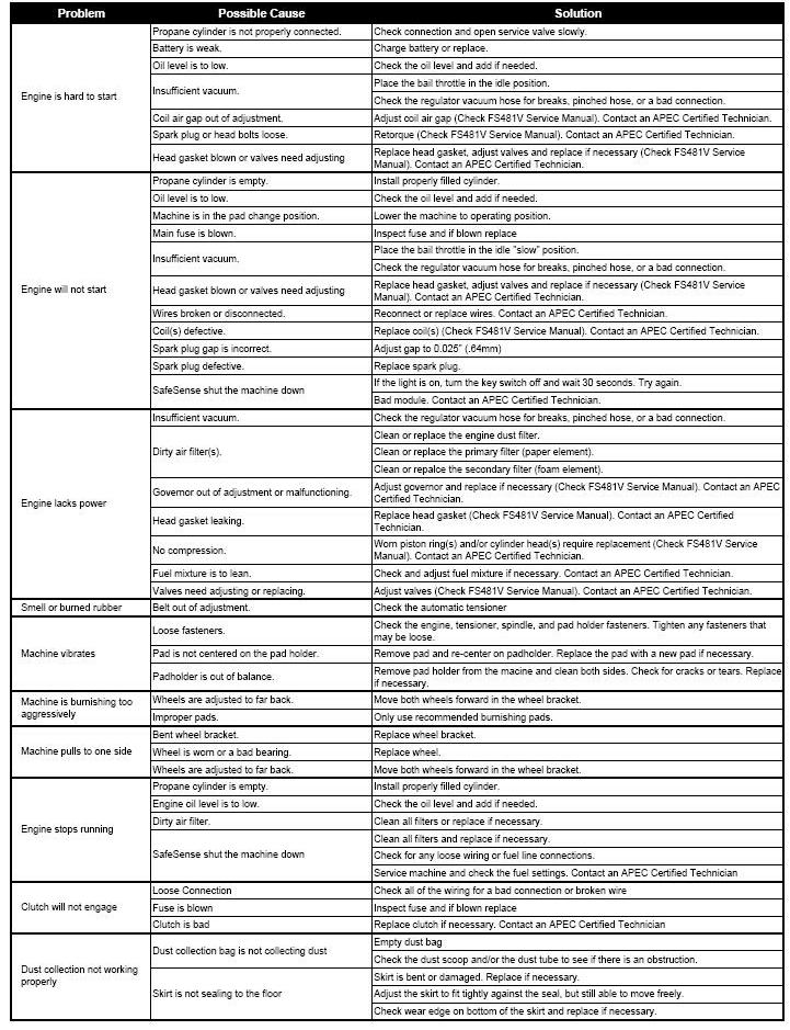
20 Machine Troubleshooting 14
21 Scheduled Maintenance Operation Daily First 8 Hrs. Every 50 Hrs. Every 100 Hrs. Check & add engine oil Check for loose or lost fasteners Check for oil leakage Inspect fuel hose and connections Clean Engine dust filter Inspect pad holder Change Engine Oil Change engine oil filter Check & clean air cleaner paper element Check & clean air cleaner foam element Inspect battery and battery connections Replace air cleaner paper element Replace air cleaner foam element Inspect, clean, & re-gap spark plugs, Replace if necessary Check & adjust valve clearance.* Retorque heads.* Clean & lap valve seating surface.* Check engine emissions* Clean cooling fins Inspect drive belt Inspect burnishing head assembly Replace drive belt Interval Every 200 Hrs. As Required * Check FS481V Service Manual. Contact Amano Pioneer Eclipse Certified Technician. Every 300 Hrs. Every 400 Hrs. Every 500 Hrs. 15


 Note: If the oil level is too high, remove the excess oil by loosening the oil drain valve. CAUTION! Do not fill above the \"FULL\" mark.")

22 Maintenance Oil Level Inspection 5. Place a suitable container under the end of the oil drain hose. WARNING! Be careful with hot oil being drained. It may be hot enough to cause severe burns. 1. Push machine to level surface. 2. Turn off LP cylinder and remove it. 3. Clean area around the oil gauge before removing it. 4. Remove the oil gauge and wipe it with a clean cloth. 5. The machine should be in an upright level position. If necessary, place a block under the back of the machine or apply weight to the front of the deck to maintain an upright, level position. 6. Insert the oil gauge into the tube, but do not tighten the oil gauge. 7. Check the oil level. It should be between the FULL and ADD marks on the oil gauge. Note: If the oil level is near or below the "ADD" mark, remove the oil gauge and add enough engine oil to bring oil level to the "FULL" mark. (SH or SJ SAE30 Oil) Note: If the oil level is too high, remove the excess oil by loosening the oil drain valve. CAUTION! Do not fill above the "FULL" mark. Excess oil will cause a smoking condition and may cause the engine to overheat. Oil Change 1. Change the oil after the first 8 hours of operation and every 50 hours thereafter. 2. Start and warm the engine so the oil will drain easily and completely. Push machine to a level surface. Stop the engine. 3. Turn off LP cylinder and remove it. 4. Locate the drain hose inside the bulkhead compartment. Lower the drain hose from the clamp and remove the cap on the end of oil drain hose. 6. Slowly turn the valve counter-clockwise, until the oil starts to drain. Note: In order for the oil to drain, it may be necessary to loosen the oil fill cap. 7. Close the drain valve. Place cap back on the end of the hose and place hose back in clamp. 8. Remove oil fill cap and add clean SH or SJ SAE 30 oil. Use 1.6 U.S. qt. (1.5 L) when the filter is not changed and 1.8 U.S. qt. (1.7 L) when filter is changed. 9. Screw in oil gauge. Reconnect the LP cylinder to the fuel hose. 10. Run the engine at low idle for 2 minutes. Check for leaks around the engine. 11. Stop the engine. Check the oil level (see Oil Level Inspection section). Oil Filter Replacement 1. Place a suitable container underneath the oil filter. 2. Using a strap wrench or oil filter wrench, remove the oil filter. Turn the filter counter-clockwise to remove it. 3. Apply a thin coat of new oil or grease to the oil filter seal (A). 4. Install the new filter (Amano Pioneer Eclipse part # KA ) by turning it clockwise. 5. Turn the filter until the seal contacts the mounting surface (B) of the engine. Then, turn the filter BY HAND 3/4 turn more. 6. Reconnect the LP cylinder to the fuel hose. 7. Run the engine at low idle for 2 minutes. Check for leaks around the engine. 8. Stop the engine. Check the oil level (see Oil Level Inspection section). 16

.")

23 Spark Plug Inspection and Replacement 1. Turn off LP cylinder and remove it. 2. Pull spark plug cap off of spark plug. 3. Remove spark plug by turning counter-clockwise and inspect it. Note: If the plug is oily or has carbon build up on it, clean the plug using a high flash-point solvent and a wire brush or other suitable tool. Note: If the spark plug electrodes are corroded or damaged, or if the insulator is cracked, replace the plug. Use Only Amano Pioneer Eclipse part # KA Do not use any other spark plug! 4. Measure the gap with a wire-type thickness gauge. The correct gap is.025 in (.635 mm). If the gap is incorrect, carefully bend the side electrode with a suitable tool to obtain the correct gap A: Insulator B: Center Electrode C: Plug Gap D: Side Electrode CAUTION! Do not wash the air cleaner filters. Do not oil the air filters. Do not use pressurized air to clean the air filters. 6. Inspect both primary and secondary air filters. If necessary, clean primary filter by lightly tapping and wipe seal ends with a clean cloth. If primary filter cannot be cleaned, is bent, or damaged, it must be replaced. (Amano Pioneer Eclipse part # KA ). If secondary filter is dirty, do not attempt to clean it. Replace it with a new filter (Amano Pioneer Eclipse part #KA ). 7. Check the intake hose for cracks or damage. 8. Install filters and replace cover. Inspect Fuel Hose and Connections 1. Push machine to level surface. 2. Turn off LP cylinder and remove it. 3. Inspect hoses for abrasions and other signs of wear. Replace all worn or damaged hoses. 4. Check for gas leaks by spreading a soapy water solution around all connections while the LP cylinder is reconnected and the service valve is turned ON. Air Filter Inspection and Replacement 1. Push machine to level surface. 2. Turn off LP cylinder and remove it. 3. Remove the hood to allow the filter cover to be removed. 4. Turn the two knobs 1/4 turn counter-clockwise and remove the filter cover. 5. If a leak is detected, turn off the LP cylinder. If the leak is in a hose, replace it. If the leak is at a fitting, loosen and clean it. Apply pipe-sealing compound and re-tighten it. 6. Recheck for leaks using a soapy water solution. If leaks persist at fittings, replace them and recheck with a soapy water solution once more. 5. Loosen clamp that retains filter and remove the air filter. 17
. 3. Allow the filter to air dry.")
24 Engine Dust Filter 1. The engine dust filter should be cleaned each hour and after each use by shaking out the dust and then rinsing with mild detergent. The filter can also be vacuumed with a wet-dry vacuum. 2. Squeeze out the excess water (do not wring). 3. Allow the filter to air dry. Note: Failure to maintain a clean engine filter will cause the engine to overheat. Also, it may cause the exhaust emissions to elevate to harmful levels. If necessary, replace with (APEC part number: MP373400). WARNING! A damaged pad holder rotating at a high rate of speed may be an extreme hazard if it should come apart. 6. If the pad holder needs to be removed, a 3/4 wrench will be required. Locate the wrench flats on top of the spindle shaft. With the spindle shaft secure, turn the pad holder counter clockwise until it is free of the spindle shaft. 7. Save the washer and/or spacer that is on the spindle shaft. Be sure they are in place when the pad holder is re-installed. 8. When threading the pad holder onto the spindle shaft, use the wrench to keep the shaft from turning. Be sure the pad holder is tight before proceeding. 9. Secure the pad with the centering device. 10. Lower the machine. Belt Maintenance Check and adjust valve clearance. Re-torque heads: Refer to Kawasaki s FS481V service manual. Clean and lap valve-seating surface: Refer to Kawasaki s FS481V service manual. Head Bolt Maintenance Refer to Kawasaki s FS481V service manual. Cooling Fin Maintenance A. Remove blower housing and any other shrouds. B. Clean the cooling fins as necessary using compressed air or pressure washer. C. Reinstall all housings and shrouds. Inspect Pads and Pad Holders 1. Push machine to level surface. 2. Turn off LP cylinder and remove it. 3. Place the machine in the Rok-Bak position (See Rok-Bak section.) 4. Remove centering device and inspect the pad. If the pad has worn less than 1/4 (6 mm), replace it. 5. Inspect the pad holder for cracks or damage. If the pad holder does not have any damage proceed to Step Push machine to level surface. 2. Turn off LP cylinder and remove it. 3. Place the machine in the Rok-Bak position. (See Rok-Bak section) 4. Rotate the pad drive and inspect the belt. 5. If cracks or excessive wear is present, the belt needs to be replaced. 6. To check for the proper tightness, squeeze the belt together. The belt should depress between 1/4 (0.6 cm) and 1/2 (1.3 cm). To change belt: (21 ) APEC Part Number: MP8070 (24 ) APEC Part Number: MP8049 (28 ) APEC Part Number: MP A. Remove the pad holder by holding the end of the shaft on the top of the machine with a 3/4 wrench and turn the pad holder counter-clockwise. B. Use the 3/4 wrench to turn the end of the spindle shaft on top of the machine while removing the old belt from the spindle pulley. C. Finish removing the belt from the engine pulley, or clutch, if necessary. D. Check engine pulley, or clutch for correct alignment with the spindle pulley. Check hardware attaching pulleys and/or clutch for proper tightness. E. Install the new belt onto the engine pulley or clutch. F. Reinstall the new belt onto the spindle pulley using the 3/4 wrench to turn the spindle clockwise. Make sure the belt is correctly placed on the idler pulley. G. Reinstall the pad holder onto the spindle shaft. H. Turn the machine upright in the burnishing position. I. Check belt for correct operation. Check all hardware for proper tightness. 18

25 Battery Maintenance The battery supplied with this machine is a sealed, absorbed glass mat (AGM), maintenance free type. It never needs servicing. When battery replacement is necessary, use Amano Pioneer Eclipse part #:MP Push machine to level surface. 2. Turn off LP cylinder and remove it. 3. Disconnect the BLACK negative battery cable first. Disconnect the RED positive battery cable last. 4. Loosen battery-retaining strap. 5. Lift out old battery and replace with new battery. 6. Secure battery with battery-retaining strap. 7. Connect the RED positive battery cable first. Connect the BLACK negative battery cable last. Note: Dispose of old battery in the proper manner. Most auto parts stores accept used batteries for recycling. PROPOSITION 65 WARNING Battery posts, terminals, and related accessories contain lead and lead compounds, chemicals known to the State of California to cause cancer and reproductive harm. Batteries also contain other chemicals known to the State of California to cause cancer. Wash hands after handling. Machine Storage Only authorized, trained personnel should have access to propane cylinders and machines. 1. Remove propane fuel cylinder when not in use and store it outside in a storage cage in accordance with NFPA Handbook 58 CAN/CGAB Do not release or bleed propane inside the building. Please consult your local Fire Marshal to ensure that you are in compliance with local fire codes. 2. Store machine away from objects that may fall and damage it. 3. Never store machine or fuel cylinders near an open flame or heat-producing device. 4. Make sure machine is cleaned properly before storing. 5. Never store machine with cylinders installed, or store spare cylinders in an enclosed van or trailer. 6. Store machine in a dry location, temperature not to exceed 120 F (50 C). Repacking the Machine Refer to Unpacking and repack the machine using original packing materials and container. Store machine in a dry location, temperature not to exceed 120 F (50 C). Transporting the Machine When transporting a propane powered floor machine with the fuel cylinder installed, the cylinder should be securely fastened with the service valve closed and the machine should be secured in the vehicle. Any propane fuel cylinders not installed should be securely fastened to avoid movement and damage. Never store machine with cylinder installed or store spare cylinders in an enclosed van or trailer. It is a good practice to check propane cylinders for overfilling before transporting them. If overfilled, correct before loading them in the vehicle by venting the excess propane outside in a safe area using the bleeder valve. 19
26 Machine Specifications Starting: Deck: Sound Level: 12VDC Battery Cast Aluminum < 89 db(a) Vibration: Less than 2.5 m/s 2 Engine: Engine Speed: Engine Oil: Engine Oil Capacity: Filter not removed - 1.6qt (1.5L) Filter removed - 1.8qt (1.7L) Kawasaki FS481V, 603cc Air Cooled Idle rpm High Idle rpm SAE 30 w/ API Service SH or SJ Engine Primary Air Filter (Paper Element): KA Engine Air Pre-Cleaner (Foam Element): KA Spark Plug: Spark Plug Gap: LP Cylinder Type: KA in. (0.635 mm) 20lb (9.1 kg) Vapor Withdraw 21 Machines 24 Machines Pad Size: 21 (53.3 cm) Pad Size: 24 (61.0 cm) Pad Speed: 2000 RPM Pad Speed: 1800 RPM Width: 24.5 (62.2 cm) Width: 27.5 (69.9 cm) Length (Max): 58 (148 cm) Length (Max): 61 (155 cm) Height (Max): 44.5 (113 cm) Height (Max): 44.5 (113 cm) Weight (w/o Tank): 242 lb (110kg) Weight (w/o Tank): 248 lb (113 kg) 28 Machines Pad Size: 28 (71.1 cm) Pad Speed: 1700 RPM Width: 31.5 (80 cm) Length (Max): 65.5 (167 cm) Height (Max): 44.5 (113 cm) Weight (w/o Tank): 262lb (119 kg) 20
27 Wiring Schematic
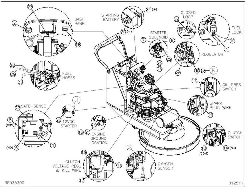
28 Connections
29 Connections Continued Ref. Part # Description Qty. A MP HARNESS, WIRING, BLKHD, w/ SAFE 1 B MP2012 HARNESS, WIRING, METER, HOUR, 27 1 C MP CABLE, BATTERY, POS., SM BOOT, 34 1 D MP CABLE, BATTERY, POS., LEFT BOOT, 14 1 E MP HARNESS, TACH/HOUR, 63 1 Ref. Part # Description Qty. F MP WIRE, SOLENOID, BATTERY 1 G SS2570 FUSE, 20 AMP, ATO 1 H MP FUSE, 7.5 AMP, ATO 1 J NB9545 NUT, SPIN LOCK, 1/ K NB7282 CLAMP, HOSE, NO
UHS Subtitle Propane Burnisher
 A company of the Group UHS Subtitle Propane Burnisher PE420BU Title We help you shine. Instructions For Use Failure to read and understand this manual before operating this machine or performing service
Propane Subtitle Stripping Machine
 A company of the Group Propane Subtitle Stripping Machine PE440ST Title We help you shine. Instructions For Use Failure to read and understand this manual before operating this machine or performing service
To Order Parts Call
 A company of the Group UHS Subtitle Propane Burnisher PE420BU Title We help you shine. Instructions For Use Failure to read and understand this manual before operating this machine or performing service
UHS Subtitle Propane Burnisher
 A company of the Group UHS Subtitle Propane Burnisher PE400BU Title We help you shine. Instructions For Use Failure to read and understand this manual before operating this machine or performing service
PE400BU Operator s Manual
 Propane Burnisher PE400BU Operator s Manual Instructions For Use Failure to read and understand this manual before operating this machine or performing service on this machine may result in injury to the
PROPANE BURNISHER INSTRUCTION MANUAL
 PROPANE BURNISHER INSTRUCTION MANUAL Read Manual Before Operating Machine 402573 Rev B Table of Contents Table of Contents... 2 Instructions for Use... 3 Specifications... 4 Safety... 5 General Guidelines
SAVE THESE INSTRUCTIONS
 OPERATION MANUAL WARHORSE IMPORTANT SAFETY INSTRUCTIONS WARNING: Failure to observe these instructions can cause personal injury to machine operator or bystanders. WARNING: Asphyxiation Hazard. An improperly
PE440BU Operator s Manual
 UHS Propane Burnisher PE440BU Operator s Manual Instructions For Use Failure to read and understand this manual before operating this machine or performing service on this machine may result in injury
A company of the PE420BU. Title. We help you shine.
 A company of the Group UHS Subtitle Propane Burnisher PE420BU Title We help you shine. Instructions For Use Failure to read and understand this manual before operating this machine or performing service
SAVE THESE INSTRUCTIONS
 OPERATION MANUAL COMMANDER IMPORTANT SAFETY INSTRUCTIONS WARNING: Failure to observe these instructions can cause personal injury to machine operator or bystanders. WARNING: Asphyxiation Hazard. An improperly
Propane Stripping Machine PE440ST Operator s Manual
 Propane Stripping Machine PE440ST Operator s Manual Instructions For Use Failure to read and understand this manual before operating this machine or performing service on this machine may result in injury
OWNER'S MANUAL 21'' & 27'' BUFFER. Powered by the E PA/Carb certified Kawasaki 603cc Engine
 OWNER'S MANUAL 21'' & 27'' BUFFER Powered by the E PA/Carb certified Kawasaki 603cc Engine... r----ll PG. 2 IMPORTANT SAFETY INSTRUCTIONS READ and UNDERSTAND all instructions and warnings before operating
PE420BU Operator s Manual
 UHS Propane Burnisher PE420BU Operator s Manual Instructions For Use Failure to read and understand this manual before operating this machine or performing service on this machine may result in injury
Table of Contents. Safety symbols... 3 Assembly 6. Operation Maintenance Troubleshooting 11. Storage. 12. Notes. 13
 Table of Contents Safety symbols... 3 Assembly 6 Operation... 8 Maintenance... 10 Troubleshooting 11 Storage. 12 Notes. 13 2 Safety Information Attention; this machine can be dangerous! All operators should
OWNER'S MANUAL WARNING DANGER. Propane cylinders sold separately. The propane cylinder must be disconnected when this firebowl is not use.
 OWNER'S MANUAL READ BEFORE USE! Model No.: BH5003-3 Style No.: 66646 For Outdoor Use Only! Use Propane Gas Only! Propane cylinders sold separately. USE PROPANE GAS ONLY! -Do not store or use gasoline or
OWNER S MANUAL. PB 24" Propane Burnisher READ THESE INSTRUCTIONS BEFORE USING. Powered by the EPA/Carb certified Kawasaki 603cc Engine
 OWNER S MANUAL PB 24" Propane Burnisher Powered by the EPA/Carb certified Kawasaki 603cc Engine READ THESE INSTRUCTIONS BEFORE USING PG. 2 IMPORTANT SAFETY INSTRUCTIONS READ and UNDERSTAND all instructions
1200W INVERTER GENERATOR
 1200W INVERTER GENERATOR MODEL NO: IG1200 PART NO: 8877070 OPERATION & MAINTENANCE INSTRUCTIONS LS0117 INTRODUCTION Thank you for purchasing this CLARKE 1200W Inverter Generator. Before attempting to use
OWNER S MANUAL. 27" LowRider CE, LEED, CARB, EPA & GS-42 COMPLIANT. Powered by the EPA/Carb Certified Kawasaki 603cc Engine
 OWNER S MANUAL 27" LowRider Powered by the EPA/Carb Certified Kawasaki 603cc Engine Available With Optional Dust Control Upgrade CE, LEED, CARB, EPA & GS-42 COMPLIANT 201 COMMERCE DRIVE MONTGOMERVILLE,
SASE Burnisher 4/ Stock Creek Blvd. Rockford, TN
 4/2015 2475 Stock Creek Blvd. Rockford, TN 37853 800.522.2606 www.sasecompany.com IMPORTANT SAFETY INSTRUCTIONS Read and observe all DANGER, WARNING, AND CAUTION statements included in the These statements
EZT715-EZT750 Owner's Manual
 EN EZT715-EZT750 Owner's Manual ESS FRC IMPORTANT: Read all safety precautions and instructions carefully before operating equipment. Refer to operating instruction of equipment that this engine powers.
Draft. Proprietary Photo. Record Engine Information to reference when ordering parts or obtaining warranty coverage. Engine Model.
 Engine Model XXxxxx Liquefied Petroleum Gas (LPG) or LPG / Natural Gas (NG) Fueled Operation Manual TP-6901 Important: Proprietary Photo Read all safety precautions and instructions carefully before operating
1-1/2 DIAMETER WATER PUMP
 1-1/2 DIAMETER WATER PUMP 2.2HP/79.8cc Engine MODEL # 101099 Operation Manual This safety alert symbol identifies important safety messages in this manual. Failure to follow this important safety information
Installation Manual. English. French
 Installation Manual For model N400 - a 4.5 cu. ft., 2-way or 3-way, refrigerator. For model N500 - a 5.5 cu. ft., 2-way or 3-way, refrigerator. For model N510 - a 5.5 cu. ft., 2-way or 3-way, refrigerator.
SPECIFICATIONS Horsepower: 1.5 HP Running Maximum PSI: 125 PSI Tank Capacity: 15 Gallons CFM: 6 40 PSI 5 90 PSI
 15 GALLON AIR COMPRESSOR Model: 7678 DO NOT RETURN TO STORE Please call 800-348-5004 for parts and service CALIFORNIA PROPOSITION 65 WARNING: You can create dust when you cut, sand, drill or grind materials
PE300BU Operator s Manual
 UHS Battery Burnisher PE300BU Operator s Manual Instructions For Use Failure to read and understand this manual before operating this machine or performing service on this machine may result in injury
1100W PORTABLE GENERATOR
 1100W PORTABLE GENERATOR MODEL NO: G1200 PART NO: 8010110 OPERATION & MAINTENANCE INSTRUCTIONS LS0312 INTRODUCTION Thank you for purchasing this CLARKE 1100W Portable Generator. Before attempting to use
PW2750 HOT WATER HI PRESSURE WASHER INSTRUCTION MANUAL
 4/10/2012 PW2750 HOT WATER HI PRESSURE WASHER INSTRUCTION MANUAL READ ALL INSTRUCTIONS AND WARNINGS BEFORE USING THIS PRODUCT. This manual provides important information on proper operation & maintenance.
Voltmaster Centrifugal Trash Pumps
 Voltmaster Centrifugal Trash Pumps Model TSP2, TSP3 and TSP4 Owner s Manual February 2011 Table of Contents 1 Introduction............................ 1 1.1 Read before using..................... 1 1.2
KT715-KT745 Owner's Manual
 EN KT715-KT745 Owner's Manual ESS FRC IMPORTANT: Read all safety precautions and instructions carefully before operating equipment. Refer to operating instruction of equipment that this engine powers.
INSPECTION/ADJUSTMENT
 3 3 INSPECTION/ADJUSTMENT SERVICE INFORMATION----------------------------------------------------------------------- 3-1 MAINTENANCE SCHEDULE-------------------------------------------------------------------
PORTABLE TRASH PUMPS MDP200
 PORTABLE TRASH PUMPS MDP200 OPERATING & PARTS MANUAL INTRODUCTION This manual provides information and procedures to safely operate and maintain the engine and pump. For your own safety and protection
Parts & Instruction Manual 28 Mirage Propane Burnisher
 Parts & Instruction Manual Table of Contents Safety Instructions... 2 Transport & Preparation... 2 Preparation... 3 Starting The Engine... 3 Operation... 4 Stopping The Engine... 4 Procedures... 4 Maintenance...
Propane torch. Model Assembly And Operation Instructions
 Propane torch Model 39953 Assembly And Operation Instructions Due to continuing improvements, actual product may differ slightly from the product described herein. 3491 Mission Oaks Blvd., Camarillo, CA
PROPANE TORCH WITH TURBO BURNER
 PROPANE TORCH WITH TURBO BURNER MODEL 91894 ASSEMBLY AND OPERATING INSTRUCTIONS 3491 Mission Oaks Blvd., Camarillo, CA 93011 Visit our Web site at http://www.harborfreight.com TO PREVENT SERIOUS INJURY,
SV471-SV601 Owner's Manual
 EN ESS SV471-SV601 Owner's Manual FRC IMPORTANT: Read all safety precautions and instructions carefully before operating equipment. Refer to operating instruction of equipment that this engine powers.
ZT710-ZT740 Owner's Manual
 EN ZT710-ZT740 Owner's Manual ESS FRC IMPORTANT: Read all safety precautions and instructions carefully before operating equipment. Refer to operating instruction of equipment that this engine powers.
North Dakota State University Grounds Maintenance Equipment
 North Dakota State University Grounds Maintenance Equipment I. Introduction Grounds maintenance equipment is an important part of the work activities on NDSU campus. They can make grounds maintenance jobs
Wheel Horse. 44 Snowthrower. for 5xi Lawn and Garden Tractors. Model No & Up. Operator s Manual
 FORM NO. 8 Rev A Wheel Horse Snowthrower for 5xi Lawn and Garden Tractors Model No. 7966 890050 & Up Operator s Manual IMPORTANT: Read this manual, and your tractor manual, carefully. They contain information
Instruction Manual. Vibratory Plate Compactor
 Instruction Manual Vibratory Plate Compactor Model VPC45R Model VPC65R Model VPC85R Model VPC95R Table of Contents 1. INTRODUCTION...1 2. SAFETY...1-2 3. SPECIFICATIONS.....2 4. APPLICATION.. 2 5. CHECK
M-3025CB-AV Fuel Pump
 SAVE THESE INSTRUCTIONS M-3025CB-AV Fuel Pump Owner s Manual TABLE OF CONTENTS General Information... 2 Safety Instructions... 2 Installation... 3 Operation... 4 Maintenance... 4 Repair... 5 Troubleshooting...
SIP Direct Drive Oil-Lube Air Compressors - Operating & Maintenance Instructions
 SIP Direct Drive Oil-Lube Air Compressors - Operating & Maintenance Instructions Please read and fully understand the instructions in this manual before operation. Keep this manual safe for future reference.
KING CANADA 950W PORTABLE GENERATOR MODEL: KCG-951G INSTRUCTION MANUAL COPYRIGHT 2011 ALL RIGHTS RESERVED BY KING CANADA TOOLS INC.
 KING CANADA 950W PORTABLE GENERATOR MODEL: KCG-951G INSTRUCTION MANUAL COPYRIGHT 2011 ALL RIGHTS RESERVED BY KING CANADA TOOLS INC. WARRANTY & SERVICE INFORMATION 1-YEAR LIMITED WARRANTY FOR THIS 950W
3. INSPECTION/ADJUSTMENT
 3 3 INSPECTION/ADJUSTMENT SERVICE INFORMATION -------------------------------------------- 3-1 MAINTENANCE SCHEDULE ---------------------------------------- 3-2 FUEL LINE/FUEL FILTER -------------------------------------------
5.5KVA GENERATOR MODEL NO: PG6500DVES OPERATION & MAINTENANCE INSTRUCTIONS PART NO: LS0616
 5.5KVA GENERATOR MODEL NO: PG6500DVES PART NO: 8857810 OPERATION & MAINTENANCE INSTRUCTIONS LS0616 INTRODUCTION Thank you for purchasing this CLARKE 5.5KVA Generator. Before attempting to use this product,
Operation Manual. 21 Inch Self-Propelled Lawn Mower MODEL #
 21 Inch Self-Propelled Lawn Mower MODEL # 106461 Operation Manual This safety alert symbol identifies important safety messages in this manual. Failure to follow this important safety information may result
PORTABLE INVERTER GENERATOR MODEL
 3200Watts PORTABLE INVERTER GENERATOR MODEL #104612 Operation Manual This safety alert symbol identifies important safety messages in this manual. Failure to follow this important safety information may
Gasoline Inverter Generator
 user manual Gasoline Inverter Generator table of contents Preface Introduction... Safety Information Exhaust fumes are poisonous... Fuel is highly flammable and poisonous... Engine and muffler may be hot...
PORTABLE TRASH PUMPS MTP200 MTP300 MTP400
 PORTABLE TRASH PUMPS MTP200 MTP300 MTP400 OPERATING & PARTS MANUAL INTRODUCTION This manual provides information and procedures to safely operate and maintain the engine and pump. For your own safety and
TP300 INDUSTRIAL TRASH PUMP OPERATOR S MANUAL
 TP300 INDUSTRIAL TRASH PUMP OPERATOR S MANUAL IT IS EXTREMELY IMPORTANT TO READ AND UNDERSTAND THE ENTIRE CONTENTS OF THIS OPERATOR S MANUAL BEFORE ATTEMPTING TO OPERATE THE PRODUCT. THIS EQUIPMENT IS
Water pump Owner's Manual
 Water pump Owner's Manual Safety Precautions I. General Safeguards Please read this operation manual to have a thorough understanding of the content there before use the product. Failure to do so may lead
107086_0607. Hustler Z BAC-VAC Owner s Manual
 107086_0607 Hustler Z BAC-VAC Owner s Manual TABLE OF CONTENTS 1. General Information...Sect. 1 2. Safety Precautions...Sect. 2 3. Assembly Instructions...Sect. 3 4. Operation...Sect. 4 5. Maintenance...Sect.
HOW - TO EMISSION CONTROL BASICS EMISSION CONTROL BASICS
 HOW - TO EMISSION CONTROL BASICS EMISSION CONTROL BASICS Tool And Material Checklist Bore Brush Thermometer Portable Vacuum Pump Screwdriver Combination Wrench Set 3/8 Drive Socket Set Tachometer Rag Service
CH940-CH1000 CV940-CV1000 Owner's Manual
 CH940-CH1000 CV940-CV1000 Owner's Manual IMPORTANT: Read all safety precautions and instructions carefully before operating equipment. Refer to operating instruction of equipment that this engine powers.
Table of Contents. Safety Assembly Pre-operation / Starting. 7. Operation.. 8. Maintenance. 9. Storage 10
 Table of Contents Safety... 3 Assembly... 6 Pre-operation / Starting. 7 Operation.. 8 Maintenance. 9 Storage 10 Parts drawings..11 Parts list by number..12 Notes.13 2 Safety Information Attention; this
Part No FJ180V KAI. 4-stroke air-cooled gasoline engine OWNER, S MANUAL
 Part No. 99920-2280-02 FJ180V KAI 4-stroke air-cooled gasoline engine OWNER, S MANUAL SAFETY AWARENESS FOREWORD TABLE OF CONTENTS Whenever you see the symbols shown below, heed their instructions! Always
ROOF WARRIOR OPERATORS INSTRUCTION MANUAL
 ROOF WARRIOR OPERATORS INSTRUCTION MANUAL Per OSHA 1926.503 it is the machine owner s responsibility to ensure that all workers using this Roof Warrior are thoroughly trained in its use and limitations.
Operation Manual. 10 Mini-Cultivator MODEL #
 10 Mini-Cultivator MODEL # 103350 Operation Manual This safety alert symbol identifies important safety messages in this manual. Failure to follow this important safety information may result in serious
AC2T & AC2T-ES INDUSTRIAL GASOLINE AIR COMPRESSOR
 AC2T & AC2T-ES INDUSTRIAL GASOLINE AIR COMPRESSOR INDUSTRIAL GAS AIR COMPRESSOR OPERATOR S MANUAL IT IS ETREMELY IMPORTANT TO READ AND UNDERSTAND THE ENTIRE CONTENTS OF THIS OPERATOR S MANUAL BEFORE ATTEMPTING
WARNING: Read these instructions before using the machine GENERATOR MODEL NO: IG3500F PART NO: OPERATION & MAINTENANCE INSTRUCTIONS
 WARNING: Read these instructions before using the machine GENERATOR MODEL NO: IG3500F PART NO: 8877100 OPERATION & MAINTENANCE INSTRUCTIONS ORIGINAL INSTRUCTIONS LS0217 INTRODUCTION Thank you for purchasing
Operating and Assembly Manual
 Model 470-/H/PRO/IC Operating and Assembly Manual Midwest Equipment Manufacturing, Inc. 5225 Serum Plant Road Thorntown, IN 46071 11-11-11 SAFETY RULES Remember, any power equipment can cause injury if
IMPORTANT INFORMATION
 Table of Contents IMPORTANT INFORMATION Section 1B - Maintenance MAINTENANCE 1 B Specifications........................... 1B-1 Special Tools........................... 1B-2 Mercury/Quicksilver Lubricants
Operating and Assembly Manual
 Model 1080 Operating and Assembly Manual Midwest Equipment Manufacturing, Inc. 5225 Serum Plant Road Thorntown, IN 46071 08-02-16 SAFETY RULES Remember, any power equipment can cause injury if operated
PORTABLE CONCRETE VIBRATOR
 PORTABLE CONCRETE VIBRATOR OPERATION MANUAL MODEL PV45S INTRODUCTION We have taken care in the selection, testing and design of this product. Should service or spare parts be required this can be provided
Owner s/operator s Manual
 Water Pump MP2533E2 Owner s/operator s Manual Completely read and understand this manual before using this product. Foreword This Owner s/ Operator s Manual is designed to familiarize the operator with
FORZA BOLT OUTBOARD MOTOR OWNER S MANUAL
 FORZA BOLT OUTBOARD MOTOR OWNER S MANUAL Table Of Contents 1.Introduction...1 2.Safety Information.1 3.Refuelling Information...1 4.Safety Matters 2 5.Preparation.3 6.Operation.3 7.Maintenance...4 8.Storage...5
KS530-KS595 Owner's Manual
 EN ESS KS530-KS595 Owner's Manual FRC IMPORTANT: Read all safety precautions and instructions carefully before operating equipment. Refer to operating instruction of equipment that this engine powers.
3KVA DUAL VOLTAGE GENERATOR MODEL NO: PG3800DV
 3KVA DUAL VOLTAGE GENERATOR MODEL NO: PG3800DV PART NO: 8857815 OPERATION & MAINTENANCE INSTRUCTIONS LS1016 INTRODUCTION Thank you for purchasing this CLARKE 3KVA Dual Voltage Generator. Before attempting
Pump Owner s Manual. PLEASE! Read All Instructions Carefully Before Installing Pump
 Pump Owner s Manual PLEASE! Read All Instructions Carefully Before Installing Pump Guarantee Associate Engineering Corporation warrants that pumps purchased from them will be free of defects in material
FSG175 FENCE STAPLE GUN
 Kencove Farm Fence Supplies 344 Kendall Rd Blairsville, PA 15717 1-800-KENCOVE sales@kencove.com www.kencove.com OPERATING MANUAL FSG175 FENCE STAPLE GUN To reduce the risk of possible injury, read the
Hydraulic Immediate Need Power Pack
 Safety, Operation, and Maintenance Manual WARNING Improper use of this tool can result in serious bodily injury This manual contains important information about product function and safety. Please read
44 and 52 Twin Bagger 100 Series Z Master
 Form No. 7 87 and 5 Twin Bagger 00 Series Z Master Model No. 7855 Serial No. 000000 and Up Operator s Manual English (CE) Contents Page Introduction................................ Safety.....................................
FX850V. 4 stroke air-cooled V-twin gasoline engine OWNER S MANUAL
 FX850V 4 stroke air-cooled V-twin gasoline engine OWNER S MANUAL SAFETY AWARENESS Whenever you see the symbols shown below, heed their instructions! Always follow safe operating and maintenance practices.
AIR-COOLED DIESEL GENERATOR OWNERʼS MANUAL. This manual contains important safety information. TDG2500E TDGW7000E TDG7000SE TDG4500E
 AIR-COOLED DIESEL GENERATOR OWNERʼS MANUAL This manual contains important safety information. TDG2500E TDGW7000E TDG7000SE TDG4500E TDG8000-3 TDG7000SE-3 TDG7000E TDG8000E TDGW7000SE TDG7000E3 TDGW8000E
TR SERIES 20 HP PROPANE BURNISHERS MODELS:TR-21, TR-24 & TR-27
 TR SERIES 20 HP PROPANE BURNISHERS MODELS:TR-21, TR-24 & TR-27 INTRODUCTION O PERATING & MAINTENANCE INSTRUCTIONS READ THIS BOOK This operator s book has important information for the use and safe operation
GENERATOR MODEL NO: FG2500 OPERATION & MAINTENANCE INSTRUCTIONS PART NO: LS0114
 GENERATOR MODEL NO: FG2500 PART NO: 8857727 OPERATION & MAINTENANCE INSTRUCTIONS LS0114 INTRODUCTION Thank you for purchasing this CLARKE Generator. Before attempting to use this product, please read this
AIR COMPRESSOR OPERATING INSTRUCTION AND PARTS LIST
 AIR COMPRESSOR OPERATING INSTRUCTION AND PARTS LIST BELT TYPE IMPORTANT PLEASE MAKE CERTAIN THAT THE PERSON WHO IS TO USE THIS EQUIPMENT CAREFULLY READS AND UNDERSTANDS THESE INSTRUCTIONS BEFORE STARTING
MODEL 565CKG Operating and Assembly Manual Midwest Equipment Manufacturing, Inc Serum Plant Road Thorntown, IN 46071
 MODEL 565CKG Operating and Assembly Manual Midwest Equipment Manufacturing, Inc. 5225 Serum Plant Road Thorntown, IN 46071 11-20-14 SAFETY RULES Remember, any power equipment can cause injury if operated
CH640, CH730, CH740. Liquefi ed Petroleum Gas (LPG) or LPG/Natural Gas (NG) Fueled Owner's Manual
 or LPG/Natural Gas (NG) Fueled Owner's Manual") CH640, CH730, CH740 Liquefi ed Petroleum Gas (LPG) or LPG/Natural Gas (NG) Fueled Owner's Manual IMPORTANT: Read all safety precautions and instructions carefully before operating equipment. Refer to operating
CH640, CH730, CH740 Liquefi ed Petroleum Gas (LPG) or LPG/Natural Gas (NG) Fueled Owner's Manual IMPORTANT: Read all safety precautions and instructions carefully before operating equipment. Refer to operating
720W PORTABLE GENERATOR
 720W PORTABLE GENERATOR MODEL NO: G720 PART NO: 8857800 OPERATION & MAINTENANCE INSTRUCTIONS LS0214 INTRODUCTION Thank you for purchasing this CLARKE 720W Portable Generator Before attempting to use this
8500M INDUSTRIAL GASOLINE GENERATOR OPERATOR S MANUAL
 8500M INDUSTRIAL GASOLINE GENERATOR OPERATOR S MANUAL IT IS EXTREMELY IMPORTANT TO READ AND UNDERSTAND THE ENTIRE CONTENTS OF THIS OPERATOR S MANUAL BEFORE ATTEMPTING TO OPERATE THE PRODUCT. THIS EQUIPMENT
Operating instructions Form no safety definitions
 Operating instructions Form no. 1000437 safety definitions safety symbols are used to identify any action or lack of action that can cause personal injury. Your reading and understanding of these safety
GENERATOR MODEL NO: FG3005 OPERATION & MAINTENANCE INSTRUCTIONS PART NO: LS0413
 GENERATOR MODEL NO: FG3005 PART NO: 8857707 OPERATION & MAINTENANCE INSTRUCTIONS LS0413 INTRODUCTION Thank you for purchasing this CLARKE Generator. Before attempting to use this product, please read this
LAWN MOWER OWNER S MANUAL
 LAWN MOWER OWNER S MANUAL Woodies SKU: 1153279 & 1153280 CAUTION: Read and follow all Safety Rules and Instructions before operating this equipment Thank you for choosing our Gasoline Lawnmower. 1 To ensure
OWNER S MANUAL ULTRAEDGE
 OWNER S MANUAL ULTRAEDGE Propane Concrete Edger PG. 2 ULTRAEDGE IMPORTANT SAFETY INSTRUCTIONS READ and UNDERSTAND all instructions and warnings before operating this machine!! Do not store or use gasoline
MODEL CJ-95 CoilJet Portable HVAC Coil Cleaning System
 MODEL CJ-95 CoilJet Portable HVAC Coil Cleaning System OPERATING AND MAINTENANCE INSTRUCTIONS CJ-95 Manual 2009 All Rights Reserved 07/2009 Table of Contents Warranty... 1 Important Safety Instructions...
MODEL HD99 HYDRAULIC ONE MAN TOWABLE EARTHDRILL
 DO NOT THROW AWAY IMPORTANT MANUAL MODEL HD99 HYDRAULIC ONE MAN TOWABLE EARTHDRILL Operators Manual GROUND HOG, INC. P.O.BOX 290 San Bernardino, CA. 92402 Phone (909) 478-5700 Fax (909) 478-5710 E-mail:
Operator s Manual Signature Series
 Operator s Manual Signature Series Signature Series Operator Manual 1 WARNING READ & UNDERSTAND OPERATOR S MANUAL BEFORE USING THIS MACHINE This symbol is used throughout this manual to warn of hazards
LDG6000SA DIESEL GENERATOR OWNERS MANUAL
 LDG6000SA DIESEL GENERATOR OWNERS MANUAL BEFORE OPERATING THIS EQUIPMENT PLEASE READ THESE INSTRUCTIONS CAREFULLY Preface Thank-you for purchasing this generator. This operation manual contains information
AIR CLEANER GENERAL REMOVAL. 1CAUTION Do not run engine without filter element in place. Debris could be drawn into the engine causing damage.
 AIR CLEANER GENERAL The air cleaner prevents foreign material from entering the carburetor and engine by trapping airborne dust and dirt in the filter element. Service air cleaner filter element every
Single and Double Head Powered Screed. Screed King. User Manual. SCR-UM EN-04 (December 2018)
") Single and Double Head Powered Screed Screed King SCR-UM-00364-EN-04 () User Manual Single and Double Head Powered Screed, Screed King CONTENTS Scope of This Manual.............................................
Single and Double Head Powered Screed Screed King SCR-UM-00364-EN-04 () User Manual Single and Double Head Powered Screed, Screed King CONTENTS Scope of This Manual.............................................
Installation Instructions for Load Management Kit A051C329
 Instruction Sheet 12-2014 Installation Instructions for Load Management Kit A051C329 1 Introduction The information contained within is based on information available at the time of going to print. In
HD675, HD775 Owner's Manual
 EN ESS HD675, HD775 Owner's Manual FRC IMPORTANT: Read all safety precautions and instructions carefully before operating equipment. Refer to operating instruction of equipment that this engine powers.
Loose Parts Note: Determine the left and right sides of the machine from the normal operating position.
 Brake Kit Dingo TX 0 & Compact Utility Loader Part No. 0 0 & 0 Loose Parts Note: Determine the left and right sides of the machine from the normal operating position. Description Qty. Use Drive wheel Brake
950 Watts (104609) /1200Watts (104610) /2000Watts (104611) PORTABLE INVERTER GENERATORS. MODELS #104609, # and #
 /1200Watts (104610) /2000Watts (104611) PORTABLE INVERTER GENERATORS. MODELS #104609, # and #") 950 Watts (104609) /1200Watts (104610) /2000Watts (104611) PORTABLE INVERTER GENERATORS MODELS #104609, #104610 and #104611 Operation Manual This safety alert symbol identifies important safety messages
950 Watts (104609) /1200Watts (104610) /2000Watts (104611) PORTABLE INVERTER GENERATORS MODELS #104609, #104610 and #104611 Operation Manual This safety alert symbol identifies important safety messages
No part of this publication may be reproduced without written permission.
 Thank you for purchasing a Honda generator. This manual covers operation and maintenance of the EB3000 and EB4000 generators. All information in this publication is based on the latest product information
OPERATOR S MANUAL 7(5 & ( 8&. $5.00 P/N REV.B
 OPERATOR S MANUAL &281 2817( 7(5 %$/$1&( /,)7 7758& 8&. $5.00 P/N 901345 REV.B As a lift truck operator, you are responsible for a machine that is useful, powerful, and can be hazardous if not operated
OPERATING & INSTRUCTION MANUAL
 251 Welsh Pool Rd Exton, PA 19341 610-941- 4333 www.safetyhoistcompany.com OPERATING & INSTRUCTION MANUAL VH-300 BRIGGS & STRATTON VH-300 HONDA IMPORTANT RETAIN THIS MANUAL For instruction on assembly
PCH680, PCH740 PCV680, PCV740
 PCH680, PCH740 PCV680, PCV740 Propane Electronic Fuel Injection (EFI) Owner's Manual IMPORTANT: Read all safety precautions and instructions carefully before operating equipment. Refer to operating instruction
OPERATION & MAINTENANCE INSTRUCTIONS
 WARNING Read the instructions before using the machine PETROL DRIVEN POWER WASHER MODEL NO: TIGER1700 PART NO: 7320054 OPERATION & MAINTENANCE INSTRUCTIONS LS0511 2 INTRODUCTION Thank you for purchasing
OPERATIONS MANUAL. Battery Burnisher
 OPERATIONS MANUAL Battery Burnisher BB20N 20 Non-Traction drive BB20T 20 Traction Drive BB24T 24 Traction Drive IPC Eagle 3650 Dodd Rd, Eagan MN 55123 800.486.2775 www.ipceagle.com 1 Instructions For Use