OM944T For Models: M944T and M38CR2 OPERATOR S MANUAL. Marine Generators Marine Diesel Engines
|
|
|
- Caitlin Carter
- 5 years ago
- Views:
Transcription


1 OM944T For Models: M944T and M38CR2 OPERATOR S MANUAL Marine Generators Marine Diesel Engines
2 CALIFORNIA Proposition 65 Warning: Diesel engine exhaust and some of its constituents are known to the State of California to cause cancer, birth defects, and other reproductive harm. Northern Lights th Avenue N.W. Seattle, WA Tel: (206) Fax: (206) Copyright 2017 Northern Lights, Inc. All rights reserved. Northern Lights, and the Northern Lights logo are trademarks of Northern Lights, Inc. Printed in U.S.A. PART NO.: OM944T 3/17
3 OPERATOR'S MANUAL for Northern Lights M944T and M38CR2 Diesel Generator Sets Read this operator's manual thoroughly before starting to operate your equipment. This manual contains information you will need to run and service your new unit. Table of Contents INTRODUCTION...2 Model Numbers...2 Serial Numbers...2 WARRANTY...3 SAFETY RULES LOCK OUT / TAG OUT PROCEDURES... 8 COMPONENT LOCATIONS M944T Generator Set M38CR2 Generator Set CONTROL PANELS Northern Lights Generator Sets OPERATING PROCEDURES Break-in Period Before Starting Starting Operating Stopping Shutdowns and Alarms Spare Parts SERVICING (Continued) V-Belts Valve Clearances Fuels - General Fuel Filters Bleeding the Fuel System Injector Service Injection Pump Turbocharger Cooling System Heat Exchanger Raw Water Pump Zinc Electrodes Electrical System - General Booster Batteries Battery Care Winterizing / Out-of-Service TROUBLESHOOTING Electrical Engine WIRING DIAGRAMS AC Electrical DC Electrical SERVICING SCHEDULE CHART SERVICING Lubrication - General Checking Oil Oil Changes Changing Oil Filter Air Filter Proprietary Information This publication is the property of Northern Lights, Inc. It may not be reproduced in whole or in part without the written permission of Northern Lights, Inc. Northern Lights, Inc. All rights reserved. Litho U.S.A. Publication number OM944T 3/17 1
4 Introduction The servicing of marine engines and generator sets presents unique problems. In many cases, boats cannot be moved to a repair facility. Marine engines cannot be compared to the servicing of automobiles, trucks, or even farm equipment. Failures often occur in remote areas far from competent assistance. Marine engines are taxed far more severely than auto or truck engines; therefore, maintenance schedules must be adhered to more strictly. Failures begin with minor problems that are overlooked and become amplified when not corrected during routine maintenance. As operator, it is your obligation to learn about your equipment and its proper maintenance. This is not a comprehensive technical service manual. Nor will it make the reader into an expert mechanic. Its aim is to aid you in maintaining your unit properly. Unit Identification MODELS INCLUDED This manual covers the operating instructions for: M944T and M38CR2 marine and commercial generator sets, which use the 944 engine block, turbocharged. Model Numbers Model Numbers Model numbers give the unit's application, block model, aspiration, and RPM: M 944 T M - Northern Lights marine generator set + Model number of engine block Bore Cylinders 94 mm 4 + T - Turbocharged M944T = Northern Lights marine diesel generator set with a 944 engine and a LX-E 34E series generator end. M38CR2 = Northern Lights commercial marine diesel generator set with a 944 engine and a Newage series generator end, 38 kw. Serial Numbers Serial Part Duty KW Your set has three serial numbers: 1 an engine number stamped on a plate attached to the valve cover, 2 a generator end serial number, and 3 a generator set serial number. Adapter KVA Frame Lead Amb. C RPM Phase Hertz Rule NEMA Insula. Rise PF Volts Volts Amps Amps FL V DC FL Amp Northern Lights, Inc., Seattle, WA U.S.A. (206) ISO:9001 Certified NOTE: Always use the generator set serial number when ordering parts or in correspondence. The generator set serial number plate is found on the service side of the generator and resembles the drawing in Figure 1. Figure 1: Generator set serial number plate. 2
5 Revised 7/12/13 Warranty A warranty registration certificate is supplied with your set. It entitles the original purchaser of our equipment to a warranty covering material or assembly faults. The extent of coverage is described in the Limited Warranty Statement. We recommend that you study the statement carefully. Safety Rules NOTE: If the warranty is to apply, the servicing instructions outlined in this manual must be followed. If further information is needed, please contact an authorized dealer or the factory. NOTICE: Accident reports show that careless use of engines causes a high percentage of accidents. You can avoid accidents by observing these safety rules. Study these rules carefully and enforce them on the job. IMPORTANT SAFETY INSTRUCTIONS. Electromagnetic equipment, including generator sets and their accessories, can cause bodily harm and life threatening injuries when improperly installed, operated or maintained. To prevent accidents be aware of potential dangers and act safely. READ AND FOLLOW ALL SAFETY INSTRUCTIONS IN THIS MANUAL, PRIOR TO THE INSTALLATION OF ANY GENERATOR SET OR ACCESSORY. KEEP THESE INSTRUCTIONS FOR FUTURE REFERENCE. Recognize Safety Symbols and Instructions In addition to the information found in this section, this operator s manual uses three different signal words to outline potential dangers of a specific nature. DANGER indicates a hazardous situation which, if not avoided, will result in death or serious injury. WARNING indicates a hazardous situation which, if not avoided, could result in death or serious injury. CAUTION indicates a hazardous situation which, if not avoided, could result in minor or moderate injury. Follow All Safety Instructions Carefully read and understand all safety messages in this manual and on your machine s safety signs. Keep signs in good and clean condition. Replace missing or damaged signs. Be sure new equipment components and repair parts include the current safety signs. For replacement signs, proper placement of safety signs or clarification on any safety issue, consult your Northern Lights dealer or the factory. There can be additional safety information contained on parts and components from outside suppliers that is not reproduced in this manual. Consult the suppliers for additional safety information. Learn how to operate the machine and how to use the controls properly. Only trained personnel should operate machines, or work on or around them. Keep you machine in proper working condition. UNAUTHORIZED MODIFICATIONS TO THE MACHINERY MAY IMPAIR ITS FUNCTION AND SAFETY PARAMETERS. Prevent Bypass and Accidental Starting Do not start engine by shorting across start terminal. Engine will start if normal circuitry is bypassed, creating a hazard by runaway machinery. Start engine only from operator s station. Handle Fuel Safely - Avoid Flames Diesel is highly flammable and should be treated with care at all times. Do not refuel while smoking or when near sparks or open flame. ALWAYS STOP ENGINE BEFORE FUELING MACHINE. Always fill portable fuel tank outdoors. Never fuel a hot engine. 3
6 Added 12/12/12 Prevent accidental discharge of starting fluids by storing all cans in a cool, safe place, away from sparks or open flame. Store with cap securely on container. Never incinerate or puncture a fuel container. Safety Rules (Continued) Operating equipment requires the full attention of the operator. Do not use radio or music headphones while operating machinery. Prevent fires by keeping machine clean of accumulated trash, grease and debris. Always clean any spilled fuel as swiftly as possible. Do not store oily rags, which can ignite and burn spontaneously. Be prepared if a fire starts. Keep a first aid kit and fire extinguisher handy. Keep emergency contact numbers for fire department, doctors, ambulance and hospital near the telephone. Service Machines Safely Do not wear a necktie, scarf, necklace, rings or other jewelry, or any loose clothing when working near moving parts. Tie long hair behind your head. If any of these items get caught in moving machinery, severe injury or death could result. Check for any loose electrical connections or faulty wiring. Look completely around engine to make sure that everything is clear before starting. Practice Safe Maintenance Understand all service procedures before starting work. Keep area clean and dry. Never lubricate, service, or adjust machine while it is in operation. Keep hands, feet and clothing away from powerdriven equipment. When shutting down an engine, disengage all power and operator controls. Allow the engine to cool completely before beginning any service work. Securely support any machinery elements that must be raised for service work with support or lifting machinery specifically intended for that purpose. Keep all parts in good conditions and properly installed. Fix damage immediately. Replace any worn or broken parts. Remove any build up of grease, oil or debris. Disconnect battery ground cable (-) before making any adjustments or service work. Stay Clear of Rotating Drivelines Wear Protective Clothing To prevent catching anything in moving machinery, always wear close fitting clothes and safety equipment appropriate to the job. Prolonged exposure to loud noise can cause hearing loss or impairment. Wear suitable authorized hearing protection, such as earmuffs or plugs to protect against loud noises. Entanglement in rotating drivelines can cause serious injury or death. Keep shields in place at all times. Make sure that rotating shields turn freely in pace with the drivelines. Do not wear loose fitting equipment around rotating drivelines. Stop the engine and make sure that all moving parts have stopped before making any adjustments, connections, or performing any other type of service to the engine or other driven equipment. 4
7 Added 12/12/12 Install all Safety Guards Direct contact with rotating fans, belts, pulley and drives can cause serious injury. Keep all guards in place at all times during engine operation. Wear close-fitting clothes. Stop the engine and be sure all fans, belts, pulleys and drives are stopped before making adjustments, connections, or cleaning near fans and their components. Do not allow anything on your person to dangle into or come in contact with a moving fan, belt, pulley or drive. Fans can act as vacuums and pull materials up from below, so avoid that area as well while in service. Safe Battery Handling Safety Rules (Continued) To Avoid Hazards: Fill batteries only in well-ventilated areas. Wear appropriate eye protection and rubber gloves. Never use air pressure to clean batteries. Wear appropriate ventilation equipment to avoid inhaling fumes when adding electrolyte. Do not spill or drip electrolyte. Use correct jump-start procedure if required. If acid is spilled on skin or in eyes: 1. Flush skin with water. 2. Apply baking soda or lime to help neutralize acid. 3. Flush eyes with water for minutes. 4. Get medical attention immediately. If acid is swallowed: 1. DO NOT induce vomiting. 2. Drink large amounts of water or milk, without exceeding 2 liters (2 quarts) 3. Get medical attention immediately Prevent Battery Explosions Battery gas is highly flammable. Battery explosions can cause severe injury or death. To help prevent battery explosions, keep sparks, lighted matches and open flame away from the top of battery. When checking battery electrolyte level, use a flashlight. Never check battery charge by contacting the posts with a metal object. Use a volt-meter or hydrometer. Frozen batteries may explode if charged. Never charge a battery that has not been allowed to warm to at least 16 o C (60 o F). Always remove grounded (-) battery clamp first and replace ground clamp last. Sulfuric acid in battery electrolyte is poisonous and strong enough to burn skin, eat holes into clothing and other materials, and cause blindness if splashed into eyes. Battery posts, terminals, and related accessories can contain lead and lead compounds, chemicals known to the State of California to cause cancer and reproductive harm. Wash hands after handling. Handle Chemical Products Safely Direct exposure to hazardous chemicals can cause serious injury. Among the potentially hazardous chemicals that may be used with Northern Lights products are lubricants, coolants, paints and adhesives. All potentially hazardous chemicals come with a Material Data Safety Sheet (MSDS). The MSDS provides specific details on chemical products, including physical hazards, safety procedures and emergency response techniques 5
8 Added 12/12/12 Safety Rules (Continued) Read and understand the MSDS for each chemical before you start any job that includes it. Follow the procedures and use appropriate equipment exactly as recommended. Contact your Northern Lights dealer or Northern Lights factory for MSDS s used on Northern Lights products. engine has been shut off. Do not remove a filler cap unless it is cool enough to comfortably grip with bare hands. Slowly loosen cap to relieve pressure before opening fully. Avoid High Pressure Fluids Work in Well Ventilated Areas Exhaust fumes from engines contain carbon monoxide and can cause sickness or death. Work in well ventilated areas to avoid prolonged exposure to engine fumes. If it is necessary to run an engine in an enclosed area, route the exhaust fumes out of the area with an approved, leak proof exhaust pipe extension. Remove Paint Before Welding or Heating Hazardous fumes can be generated when paint is heated by welding, soldering or using a torch. To avoid potentially toxic fumes and dust, remove paint before heating. Remove paint a minimum of 100 mm (4 in.) from the area that will be affected by heat. If paint cannot be removed, wear an approved respirator. If you sand or grind paint, use an approved respirator. If you use solvent or paint stripper, remove stripper with soap and water before welding. Remove solvent or paint stripper containers from the area. Allow at least 15 minutes for fumes to disperse before welding or heating. Do not use a chlorinated solvent in an area where welding will occur. Work only in areas that are well ventilated. Dispose of paint and solvent properly. Relieve pressure prior to disconnecting pressurized lines. Escaping fluid under pressure can penetrate the skin causing serious injury. Always relieve pressure before disconnecting hydraulic or other pressurized lines. Tighten all connections firmly before re-applying pressure. If searching for leaks, use a piece of cardboard. Always protect your hands and other body parts from high-pressure fluids. If an accident occurs, see a doctor immediately. Any high pressure spray injected into the skin must be removed within a few hours to prevent the risk of gangrene or other infection. Avoid Heating Near Pressurized Fluid Lines Flammable spray can be generated by heating near pressurized fluid lines, resulting in severe burns and bodily injury. Pressurized lines can rupture when heat goes beyond the immediate flame area. Do not weld, solder or use a torch or open flame near pressurized lines or other flammable fluids. Do Not Open High-Pressure Fuel System Service Cooling System Safely Opening a pressurized cooling system can release explosive fluids and causing serious burns. Before opening any pressurized cooling system, make sure the Many Northern Lights engines use high-pressure fuel injection. High-pressure fluid remaining in fuel lines can cause serious injury. Do not disconnect or attempt any repair of fuel lines, sensors, or other 6
9 Revised Safety Rules (Continued) components between the high-pressure fuel pump and nozzles on engines with high pressure fuel systems. ONLY AUTHORIZED TECHNICIANS CAN PERFORM REPAIRS ON AN HIGH PRESSURE FUEL INJECTION SYSTEMS. for cleaning. Avoid brushing or grinding materials containing asbestos. When servicing, wear an approved respirator. A special vacuum cleaner is recommended to clean asbestos. If this vacuum is not available, apply a mist of oil or water on the material containing asbestos. Keep all bystanders away from any area where asbestos dust may be generated. Avoid Hot Exhaust Use Proper Lifting Equipment and Techniques Avoid exposure to and physical contact with hot exhaust gases. Exhaust parts and streams can reach high temperatures during operation, leading to burns or other serious injury. Cleaning exhaust filters can also lead to exposure to hot exhaust gas and the injury risk associated with it. Avoid exposure to and physical contact with hot exhaust gases when cleaning exhaust filters. During auto or manual/stationary exhaust filter cleaning operations, the engine will run at elevated temperatures for an extended period of time. Exhaust parts and streams can reach high temperatures during operation, leading to burns or other serious injury. Avoid contact with Turbo Housing The unit s turbocharger reaches very high temperatures during operation. Avoid ALL direct contact with the turbocharger/ Lifting heavy components incorrectly can cause severe injury or damage to machinery. Avoid unbalanced loads. Do not use lifting eyes. Lift the generator set using lifting bars inserted through the lifting holes on the skid. Follow all recommended removal and installation procedures in this and associated Northern Lights manuals. Use Proper Tools Makeshift tools and procedures can create safety hazards. Always use appropriate tools for the job. Use power tools only to loosen threaded parts and fasteners. For loosening and tightening hardware, always use the correct sized tools. Do not use US measurement tools on metric fasteners, or vice versa. Use only service parts that meet Northern Lights specifications. Avoid Harmful Asbestos Dust Dispose of Waste Properly Inhaling asbestos fibers may cause lung cancer. Avoid breathing any dust that may be generated when handling components containing asbestos fibers, including some gaskets. The asbestos used in these components is usually found in a resin or otherwise sealed. Normal handling of these components is not dangerous, as long as airborne dust containing asbestos is not generated. Avoid creating dust. Never use compressed air Disposing of waste improperly can threaten the environment and lead to unsafe working conditions. Potentially harmful waste used in Northern Lights equipment can include oil, fuel, coolant, filters and batteries. Use leakproof containers to drain fluid. Do not use food or beverage containers that may mislead someone into drinking from them. Do not pour waste onto the ground, down a drain or into any water source. 7
10 added Lock Out / Tag Out Procedures Scope During maintenance, repairs or retooling of a Northern Lights generator set, simply turning the machine off or unplugging it while it is being worked on does not give enough protection to others who are not performing the maintenance or repair. Many serious accidents happen when someone thought the machine was turned off, or all of its energy was safely blocked or released. General Policy To avoid dangerous or hazardous situations, refrain from any of the following: Removing or bypassing a guard or other safety device Placing any part of your body in a position where you could be caught by moving machinery. Cleaning or oiling machinery when in operation. Adjusting circuits, chillers, pumps, air handlers, valves, circuit breakers or fans while in operation. Working on piping or high pressure systems. Lock Out/Tag Out Instructions - Electrical Equipment Be sure the equipment s ON/OFF switch is in the OFF position and is unplugged from any electrical source before attempting to perform any type of work on the equipment. Obtain an electrical plug cap cover with a lockset. Secure the plug terminal end using the electrical plug lockout cap. Lock the cap and retain the key. If the equipment is directly wired into an electrical box with a shut off switch, obtain a lock pad and/or the appropriate colored tags and place the lock and tag through the shut off lever. Retain the key until the repair is completed and the machine is safe to start. Be certain the shut off lever is in the OFF position before restarting. NEVER give a lock out key to unauthorized personnel. If the equipment is directly wired into an electrical box without a shut off switch and lock out capability, then a circuit breaker lock out will be required. Obtain a circuit lock and tag set. Install the lock onto the circuit breaker box. Ensure the unit ON/OFF switch is in the OFF position before restarting. Lock Out/Tag Out Instructions - Pneumatic and Hydraulic Equipment If shutting off of air, water or other material cannot be achieved at the local supply valve, shut off valves further back in the system and re-check the bleed-off point until complete shut-off is achieved. Affix a DO NOT OPERATE tag to each valve handle that requires shut off. Each DO NOT OPERATE tag must be signed and dated by the authorized technician servicing the equipment. Lock Out/Tag Out Instructions - Air Hose Connected Pneumatic Equipment Equipment connected to the compressed air system through an air hose with a detachable fitting must be shutdown and unplugged. Excess air must be bled prior to removing the air hose, prior to any maintenance or repair activities. Affix a DO NOT OPERATE tag to the air hose near the detachable fitting. Each DO NOT OPERATE tag must be signed and dated by the authorized technician servicing the equipment. Check that the equipment cannot be operated by activating the ON switch. Stored Energy Immediately after applying Lock Out or Tag Out devices, ensure that all potentially hazardous stored or residual energy is relieved, disconnected, restrained and otherwise rendered safe. Verification of Isolation Verify the machinery or equipment is actually isolated and de-energized prior to beginning work on a machine or on equipment that has been locked out. Restarting Procedures For servicing pneumatic and hydraulic equipment, the following additional procedures must be implemented, following completion of lock out/tag out procedures for the unit to be serviced: Shut off air, water or supply valves at the equipment to be serviced. Check the local bleed-off point for completed release of pressurized air, water or oil. Follow the procedures below prior to restoring energy: Ensure that all machinery or equipment is properly reassembled. Inspect the machinery or equipment to verify non-essential items have been removed. Ensure that all personnel are safely outside danger zones. Notify personnel that lock out/tag out devices have been removed and energy will be reapplied. Only authorized personnel may remove lock out/tag out devices or notices. 8
11 added Notes 9


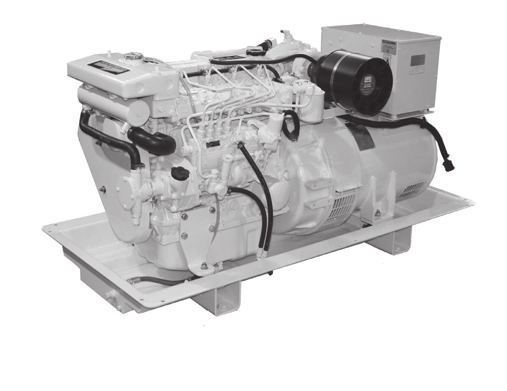
12 Updated 12/24/12 M944T Generator Set Component Locations Figure 2: M944T3 Service Side 1. Expansion Tank 2. Coolant Fill 3. Thermostat Housing 4. Rocker Arm Cover 5. Lube Oil Fill 6. Intake Manifold 7. Fuel Filter 8. Breather 9. Air Filter 10. Junction Box 11. Lube Oil Dipstick 12. Oil Filter 13. Vibration Mounts 14. Fuel Supply & Return Connections 15. Fuel Primer Pump 16. Injection Pump 17. Lube Oil Drain 18. Raw Water Pump 19. Heat Exchanger Raw Water Drain and Zinc 20. Heat Exchanger 10

13 Updated 9/28/12 M944T Generator Set Component Locations Figure 3: M944T Non-Service Side 19. Turbocharger 20. Wet Exhaust Elbow 21. Exhaust Manifold 22. Alternator 23. Belt Guard 24. Starter 25. Oil Pan 11
 11. Oil Filter 12. Fuel Primer Pump 13.")
14 M38CR2 Generator Set Component Locations Figure 4: M38CR2 Service Side (Representative only - early production) 1. Expansion Tank 2. Coolant Fill 3. Thermostat Housing 4. Fuel Filter 5. Intake Manifold 6. Air Cleaner 7. Junction Box 8. Harness Plug 9. Lube Oil Dipstick 10. Fuel Manifold (optional) 11. Oil Filter 12. Fuel Primer Pump 13. Injection Pump 14. A.C. Coolant Heater (optional) 12
 19. Turbocharger 20. Exhaust Manifold 21. Alternator 22. Belt Guard 23. Oil Pan 24.")
15 M38CR2 Generator Set Component Locations Figure 5: M38CR2 Non-Service Side (Representative only - early production) 19. Turbocharger 20. Exhaust Manifold 21. Alternator 22. Belt Guard 23. Oil Pan 24. Starter 13


16 Control Panels 1. PREHEAT/ SHUTDOWN BYPASS This switch serves two functions: 1. Preheats air before beginning the starting process. Press switch for seconds before attempting startup. 2. Bypasses the safety shutdown feature during the starting process. Keep switch engaged while starting engine, and for 2 to 3 seconds afterwards, allowing oil pressure to build beyond shutdown setpoint. Figure 6-A: Series 1-B Generator Control Panel 2. ENGINE CONTROL SWITCH To start the engine, hold this switch in the START position until the engine is running. After the engine starts, release the switch and it will return to RUN position. To stop the engine, hold the switch in the STOP position. NOTE: The rocker switch is used on Series 1 panels only, and has a light that glows when the set is running. 3. HOUR METER Keeps track of engine running time. 4. OIL PRESSURE GAUGE Shows the oil pressure in the engine lubricating system. 5. WATER TEMPERATURE GAUGE Registers the temperature of the cooling water. Figure 6-B: Series 3 Generator Control Panel 6. D.C. VOLTMETER When the engine is stopped, the voltmeter indicates the condition of the battery. When the engine is running, the voltmeter indicates the voltage output of the alternator. For Series 4 Control Panels only: 7. A.C. VOLTMETER Shows the generator output voltage. 8. FREQUENCY METER (Hertz) The frequency meter indicates alternating current frequency: 60 Hz (1800 rpm) or 50 Hz (1500 rpm). 9. AMMETER/VOLTMETER SELECTOR Used to check the voltage and current of each phase. Return to Amps Off position when not monitoring. Figure 6-C: Series 4 Generator Control Panel 10. A.C. AMMETER Shows the generator load on each phase. The phase is selected with the Ammeter Selector switch (#9). 14
17 revised Emission-Related Installation & Instructions Failing to follow these instructions when installing a certified engine in a vessel violates federal law (40 CFR (b)), subject to fines or other penalties as described in the Clean Air Act. The installed exhaust system should not create exhaust back pressure greater than 27 (686 mm) of water for a turbocharged engine and 27 (686 mm) for a nonturbocharged unit, measured at the engine exhaust elbow. If you install the engine in a way that makes the engine s emission control information label hard to read during normal engine maintenance, you must place a duplicate label on the vessel, as described in 40 CFR Operating Procedures BREAK-IN PERIOD 1. The first 100 hours on a new or reconditioned engine are critical to its life and performance. 2. Constantly check the engine temperature and oil pressure gauges. 3. Oil consumption is greater during break-in as piston rings take time to seat. 4. Break-In Oil Changes: Change engine oil and filter at 50 hours. Change oil and filter again at 100 hours (consult Lubricants section for oil recommendation). Operating Instructions: Maintain at least a 75% load on your generator set for the first 100 hours. If this is not possible, maintain no less than a 50% load to ensure proper seating of the piston rings. Vary the load to help seat the rings. BEFORE STARTING 1. Check the water level by removing the pressure cap from the expansion tank. In order to give the cooling water an opportunity to expand, the level should be about 1 in. (2.5 cm) below the filler cap sealing surface when the engine is cold. CAUTION: Use protective clothing and open the filler cap carefully when the engine is warm to prevent burns. 2. Check the oil level in the crankcase with the dipstick. The oil level must be between high and low marks on the stick. Never allow the level to go below this area. Always add the same viscosity of oil as is already in the crankcase. 3. Check the fuel tank level and open any fuel valves on the tank and at the secondary fuel filter. 4. Close the sea-cock, check and clean the sea strainer, and reopen the sea-cock. 5. Place the battery switch in the ON position. NOTE: The battery switch must always be kept ON while the engine is running. If the switch is turned OFF while the engine is running, the battery charging alternator could be damaged. 15
18 Operating Procedures STARTING 1. Hold the Shutdown Bypass switch in the ON position. 2. While holding the Shutdown Bypass switch in the ON position, push the Engine Control switch to the START position. 3. As soon as the engine starts, release both switches. Do not crank the starter for more than 10 seconds consecutively. If the engine fails to start with the first attempt, be sure that it has stopped completely before re-engaging the starter. NOTE: Excessive cranking of the starter on marine sets equipped with a water lift muffler can cause engine damage. If the engine does not start after 3 consecutive 10-second cranks, remove the impeller from the seawater pump. This will prevent the muffler from filling with water and backfilling the exhaust line and engine. Once the engine starts, shut if off immediately and reinstall the impeller. Restart and check the exhaust overboard outlet for gushes of water. OPERATING 1. Units with Series 3 and Series 4 Control Panels: check gauges often. Oil pressure must be above 15 PSI. The D.C. voltmeter should read between 11 and 15 volts at 80 F (25 C) ambient temperature. The water temperature gauge must be below 200 F (94 C). Check the A.C. voltage and frequency meters (Series 4 panel). If the gauges deviate from normal levels, shut down the generator set and investigate. 2. Add electrical load. STOPPING 1. Remove electrical load from the generator set. 2. Run the engine for a two to three minute cool-down period. 3. Move the Engine Control switch to the STOP position. 16
19 Operating Procedures SHUTDOWNS AND ALARMS 1. Your unit is fitted with a system to protect it from high water temperature or low oil pressure. a. Generator sets have shutdown systems to stop the engine. They have no warning horns. b. Other alarms and shutdowns are available as optional equipment. NOTE: If your unit is equipped with optional shutdowns and alarms, do not rely on your warning or shutdown system to the exclusion of careful gauge monitoring. Watching your gauges can prevent damage to the unit and dangerous power losses. 2. Do the following when your warning or shutdown system is activated: a. Check the temperature gauge. If above 205 F (96 C), shut off the engine immediately. b. Use the Trouble Shooting Guide on page 25 to isolate the cause of the overheat. CAUTION: Do not remove the water fill cap of an overheated engine. Escaping high temperature steam can cause severe burns. Allow the engine to cool and then remove the cap slowly using protective clothing. SPARE PARTS 1. ADE recommends that you keep the following spare parts on hand for field service. The parts are available from your local Northern Lights dealer. Some marine models may already have On-Board Kits, a handy box that contains the most common parts you will need. a. Primary and secondary fuel filter elements b. Oil filters c. Air filter elements d. Alternator belt e. Thermostat and gaskets f. Seawater pump impeller and gaskets g. Glow plugs h. Injector and washer 2. If your set is operating a long distance from a servicing dealer, add the following: a. Complete set of injectors b. Copper washers for injector change c. Complete set of glow plugs d. Fuel lift pump c. Make repairs and restart after the temperature gauge registers below 200 F (94 C). d. Watch the temperature gauge regularly and turn off the unit if the temperature rises above 205 F (96 C). Repeat troubleshooting. 3. If shutdown is activated and the temperature gauge shows temperature within normal temperature range: a. Check the engine crankcase oil level. b. If the oil level is low, fill with recommended lubricating oil and restart. Watch the oil pressure gauge carefully and shut off the engine if it does not show a normal reading (20-60 PSI) after a few seconds of operation. c. If the oil level is normal, DO NOT restart the engine. Call your dealer for assistance. 17
20 Servicing Schedule Chart The Servicing Schedule Chart below shows the service schedule required for proper maintenance of your generator set. More detailed coverage of each Service Point (SP) is listed on the page noted in the page column. DAILY: SP1 SP8 SP16 Check oil level in engine Check primary fuel filter Check cooling water level Check sea strainer AFTER FIRST 50 HOURS: SP2/3 Change engine oil and filter SP5 Check V-belt tension SP21 Check electrolyte level in batteries EVERY 50 HOURS: SP5 Check V-belt tension SP21 Check electrolyte level in batteries AFTER FIRST 100 HOURS: SP2/3 Change engine oil and filter EVERY 250 HOURS: SP2/3 Change engine oil and filter EVERY 250 HOURS cont.: SP4 Check air cleaner SP14 Check turbocharger SP20 Check zinc electrodes EVERY 500 HOURS: SP6 Check valve clearances SP9 Change primary fuel filter element SP10 Change secondary fuel filter SP12 Check injectors SP17 Check cooling system SP19 Change impeller SP22 Check state of charge of batteries EVERY 1000 HOURS or as needed: SP4 Change air cleaner SP13 Check fuel injection pump SP18 Check and clean heat exchanger SP24 Inspect starter and alternator SERVICE POINT PAGE OPERATION DAILY Hours Hours Hours Hours Hours ENGINE: SP1 12 Check oil level SP2 12 Change engine oil 1, 5 SP3 13 Change lube oil filters 1, 5 SP4 13 Check air cleaner 1, 3, 4 SP5 13 Check V-belt tension 1, 5 SP7 14 Check valve clearances 8 FUEL SYSTEM: SP8 15 Check primary filter 2 SP9 15 Change primary filter element 2, 3 SP10 15 Change secondary fuel filter 1, 3 SP11 16 Bleed the fuel system 3 SP12 17 Check injectors 1, 6 SP13 18 Check fuel injection pump 3 TURBOCHARGER: SP14 19 Check air, oil, & cooling water lines for leakage 1 COOLING SYSTEM: SP16 20 Check cooling water level SP17 20 Check and flush cooling system 7 SP18 21 Check and clean heat exchanger SP19 21 Change impeller in raw water pump 1, 3 SP20 21 Check zinc electrodes 3 ELECTRICAL SYSTEM: SP21 23 Check electrolyte level in batteries 1, 3 SP22 23 Check condition of batteries with hydrometer 1 SP24 24 Inspect alternator and starter 3 OUT OF SERVICE: SP23 23 Winterizing or out-of-service 3 1) Perform maintenance once a year even if hour level has not been reached. 2) Consult manufacturer's maintenance schedule, note on chart. 3) Or Whenever necessary. 4) Change at 1000 hours. 5) After first 50 hours. 6) Fuel inj. valve opening pressure: MPa (120 kgf/cm 2 ) 1710 PSI. 7) Or every 2 years. 8) Valve clearance =.25 mm ( ). 18
21 Service Record Service Point OPERATION HOURS/ DATE 50 HOURS SP5 Check V-belt tension SP21 Check electrolyte in batteries 250 HOURS SP2 SP3 SP4 SP14 SP20 Change engine oil Change lubricating oil filters Check air cleaner Check turbocharger Check zinc electrodes EVERY 500 HOURS SP7 SP8 SP10 SP12 SP19 SP22 Check valve clearances Change primary filter element Change secondary fuel filter Check injectors Change impeller in seawater pump Check condition of batteries with hydrometer 1000 HOURS or as required SP13 SP18 Check fuel injection pump Check and clean heat exchanger Service Notes: 19
22 Servicing LUBRICATION - GENERAL 1. Use only clean, high quality lubricants stored in clean containers in a protected area. 2. These lubricants are acceptable: a. API Service CD, CE, and CF-4 single viscosity oils. b. API Service CD, CE, and CF-4 multi-viscosity oils. 3. Use the proper weight oil for your average operation temperature. Air Single Multi- Temperature Viscosity Viscosity Above 32 F SAE 30W SAE 15-40W (0 C) -10 to 32 F SAE 10W SAE 10-30W (-23 to 0 C) Figure 7: Lube Oils 4. Never put additives or flushing oil in crankcase. SP1. CHECKING OIL LEVEL 1. While the engine is stopped, check the oil level in the crankcase with the dipstick daily. The oil level must be between the high and low marks on the stick. Fill with the recommended oil, and fill only to the high mark on the dipstick. Follow the lubrication recommendations in Figure 7. SP2. OIL CHANGES 1. The set is delivered with special break-in oil. Change the engine oil and oil filter after 50 hours of operation. Use Service CC30 weight oil during the first 100 hours. 2. Change the oil and filter again at 100 hours using the oil recommended in the above paragraph. After this, change oil and filter every 250 hours. 3. During intermittent cold weather operation, change oil every 100 hours or six weeks, whichever comes first. 4. Change oil at any seasonal change in temperature when a new viscosity of oil is required. 5. Change oil when engine is warm but not hot. 6. Dispose of waste oil in an approved manner. 7. Never use a flushing oil. 8. Loosen clamp on oil change tube. Remove cap. Drain oil. Replace cap and tube. 9. Refill engine with recommended oil. 10. Engine capacity with new oil filter is: gallons (10 liters) 20
23 Servicing SP3. CHANGING LUBE OIL FILTER 1. Change the lube oil filter every 250 hours. 2. Use a filter wrench to remove old filter. Dispose of filter in approved manner. 3. Make sure the gasket from the old filter is removed and discarded. Clean mount face. 4. Spread a thin film of engine oil on the rubber gasket on the new filter and screw it on nipple until gasket meets the sealing surface. SP5. V-BELTS 1. Check the tension and wear on the V-belt after every 50 hours. 2. Use your thumb to press on the belt at the midpoint between the crankshaft and alternator pulleys. The tension is correct if the belt can be depressed about.39 to.47 in. (10-12 mm) with 22 lbs. (10 kg) force. 5. Using hands only no wrench tighten filter one-half turn farther. Overtightening can do damage to filter housing. 6. Fill engine with recommended oil. Start engine and check for leakage. Stop engine, wait 3 minutes, and check oil level. Add additional oil if necessary. 7. Oil filter part number is:...# SP4. AIR CLEANER 1. Visually inspect air cleaner every 250 hours. 2. Take off the hose clamp on the bracket and the hump hose to detach the air cleaner. 3. Make sure the hump hose is clean inside and also that the new filter element is absolutely clean and installed properly. Note: Make absolutely sure no impurities enter the engine while changing the element, and do not run the engine with the air cleaner removed. Do not clean the filter with diesel fuel, solvent, or gasoline. Serious engine damage can result. 21

24 Servicing SP7. VALVE CLEARANCES 1. Readjust valve clearance after first 50 hours of operation. Check valves every 500 hours thereafter. 2. Check the valves when the engine is cold. 3. Rotate the crankshaft in a clockwise direction in the front to bring each piston to the top dead center on the compression stroke. Top dead center (TDC) is when notch on the pulley aligns with the pointer and the two valves on cylinder No. 1 rock. Rocking is when the rocker arms (for the two valves on a given cylinder) are moving in opposite directions, one up closing the valve and one down opening the other valve. The moment when the two rocker arms are exactly aligned with each other is when they rock. Figure 9: Valve Adjustment 6. Adjust the remaining valves. 7. Replace the rocker arm cover. Figure 8: Timing Mark 4. Measure the valve clearance for each of the valves, with a feeler gauge, in the firing order ( ). Standard valve clearances for a cold engine are: Intake (IN) in. (0.25 mm) Exhaust (EX) in. (0.25 mm) Z Front 5. To adjust valve clearance, loosen the lock nut on the adjustment screw. Insert a feeler gauge between the rocker arm and the valve stem cap. Adjust, while measuring the clearance, until the feeler gauge slides with a slight drag. Tighten the lock nut and recheck the clearance (Figure 9). Tightening Cylinder Head Bolts Order 17 bolts total, Tightening Torque: 113 to 123 N m (11.5 to 12.5 kgf m) [83.2 to 90.4 lbf ft] 22
25 Servicing FUELS - GENERAL 1. Use only clean, high quality fuels of the following specifications, as defined by ASTM designation D975 for diesel fuels: a. Use grade No. 2 diesel at ambient temperatures above freezing 32 F (0 C). b. Use grade No. 1 at ambient temperatures below freezing. c. International fuel specifications: JIS K2204 ISO-8217-DMA BS 2869 Part 1 Class A1 BS 2869 Part 2 Class A2 2. Use fuel having less that 0.2% sulphur of weight (less than 0.05% recommended). 3. The cetane number should be 45 or higher. 4. Particulate contaminate should be 5.0 mg/l ( oz/u.s. gal) or lower. SP8-10. FUEL FILTER 1. Your generator set should have a primary fuel filter installed. We recommend the Northern Lights brand of fuel filters. a. Check the primary fuel filter daily as recommended by the filter manufacturer. b. Change the engine mounted filter as often as necessary or every 250 hours. c. Remove the fuel filter with a filter wrench. d. Apply a coating of fuel to the o-ring of the new fuel filter. e. Tighten the new filter by hand, do not use a filter wrench for tightening. f. The filter should be dry. g. Do not add fuel to the fuel filter before installation, as this could cause unfiltered fuel to enter the fuel pump. h. Bleed the air out of the filter. The fuel filter part number is: DO NOT use these unsuitable grades of fuel: a. Domestic heating oils, all types. b. Class B engine. c. Class D domestic fuels. d. Class E, F, G or H industrial or marine fuels. e. ASTM-D975-60T No. 4-D and higher number fuels. 6. Storing fuel: a. Keep dirt, scale, water, and other foreign matter out of fuel. b. Avoid storing fuel for long periods of time. c. Fill the fuel tank at the end of each day s operation. This will reduce condensation. 23
26 Servicing SP11. BLEEDING THE FUEL SYSTEM CAUTION: Escaping diesel fuel under pressure can penetrate skin causing serious personal injury. Before disconnecting lines be sure to relieve all pressure. Before applying pressure, be sure all connections are tight and lines, pipes and hoses aren't damaged. Fuel escaping from a very small hole can be almost invisible. Use a piece of cardboard or wood, rather than hands, to search for suspected leaks. If injured by escaping fuel, see a doctor at once. Serious infection or reaction can develop if proper medical treatment is not administered immediately. 1. Fuel system air bleeding may be needed when: a. After fuel has been added to a newly installed engine. b. A new fuel filter is installed. c. The engine has run out of fuel. d. The fuel lines, injection pump, or any other fuel system component has been removed and installed. 2. After changing the fuel filter, air only needs to be bled from the fuel filter. To do this: a. Loosen the air vent plug (#1 on Figure 10) on the fuel filter by about 1-1/2 turns. (Be sure to cover the vent with a cloth to prevent fuel from splashing.) b. Turn the priming pump cap on the fuel feed pump counterclockwise to unlatch it. Move the priming pump plunger (#2 on Figure 10) up and down. To close the pump turn the cap clockwise while depressing it. c. Close the air vent plug when no more air bubbles can be seen in the fuel flowing from the air vent plug hole. Figure 10 Fuel Feed Pump 3. To bleed air at the fuel injection pump: a. Turn the air vent plug (#3 on Figure 10) about 1-1/2 turns to loosen it. (Cover the vent with a cloth to prevent fuel from splashing.) b. Pump the feed pump cap up and down. c. When there are no air bubbles to be seen in the fuel flowing from the air vent plug hole, push down the priming pump cap and turn it clockwise to lock it in place. NOTE: Do not close the air vent plug before locking the priming pump cap in place, because the internal pressure in the pump will prevent the priming pump cap from returning to the original position. 4. If the engine does not start after this bleeding process, loosen a fuel line at the injector while cranking the engine with the starter motor until pure fuel escapes. Then tighten the connections. Do each line one-at-a-time. After the engine has started, use a piece of cardboard to look for fuel leaks. 24
27 Servicing SP12. INJECTOR SERVICE 1. Injectors should be checked every 500 hours. This check should be made by a Northern Lights dealer or local injection repair station. CAUTION: Escaping diesel fuel under pressure can have sufficient force to penetrate the skin causing serious personal injury. If injured by escaping fuel, see a doctor at once. 2. Injector removal: a. Clean loose dirt from around the injectors and the fuel lines. b. Relieve high pressure in the fuel lines by loosening the delivery line flare nuts at each injector. c. Remove delivery lines by disconnecting them from the injectors and injection pump. Remove all lines as an assembly; do not remove the spacers. Cover the ends of the lines, the injector inlets, and the injection pump outlets to keep dirt out. d. Remove the return line retaining bolts, washers, and return line. e. Loosen the injector retaining nuts at the same time a little at a time. Remove the injector. f. Remove the injector seat. Cover the holes to prevent debris from entering the cylinders. 3. Injector repair and cleaning: a. Take injectors to your Northern Lights dealer or local injection repair station for testing and service. 4. Injector installation: a. Install new injector seal washer seat and injector. Evenly tighten the injector retaining nuts to 18.1 to 25.3 ft/lbs (24.5 to 34.3 N m), or 2.5 to 3.5 kgf m. Do not overtighten. b. Reinstall the return line using new sealing washers. Tighten bolts to 13.0 to 15.9 ft/lbs (17.7 to 21.6 N m), or 1.8 to 2.2 kgf m. NOTE: Overtightening can damage injectors. c. Reinstall injection lines. Tighten flare nuts at injection pump to 19.5 to 23.9 ft/lbs (26.5 to 32.4 N m), or 2.7 to 3.3 kgf m. Leave the lines loose at injectors for bleeding. d. Bleed the injection lines. Crank the engine to fill the lines. Tighten flare nuts at injectors to 14.5 to 17.4 ft/lbs (21.0 to 23.0 N m), 2.0 to 2.4 kgf m. e. Start the engine and check for leaks using a piece of paper or cardboard. Do not use your hand to check for leaks. Note: Do not use pry bars to remove injectors from the cylinder head. 25
28 Servicing SP13. INJECTION PUMP 1. Since operating conditions may vary considerably, it is difficult to give a definite interval for checking the injection pump. But as a rule, pump settings, maximum speed, and exhaust smoke should be checked after every 2000 hours of operation. Service of the fuel injection pump should only be done if checks indicate pump malfunction. 2. Black smoke can be an indication of pump malfunction. Before servicing the pump, check other possible causes: a. Check cleanliness of the air filter. b. Check valve clearances. c. Clean and check injectors. c. Remove the injection pump drive gear cover plate and the sea water pump. d. Align timing marks on timing gears. e. Remove the pump support bracket on rear of pump. f. Remove the 4 mounting nuts. g. Take the pump to your Northern Lights dealer or an injection repair station for testing and service. 3. Any repair which involves disassembly of the injection pump must be carried out by specially trained mechanics with the proper tools and test equipment. NOTE: All warranties on the engine become null and void if the injection pump seals are broken by unauthorized persons. 4. Injection Pump Removal: CAUTION: Escaping diesel fuel under pressure can have sufficient force to penetrate the skin, causing serious personal injury. If injured by escaping diesel fuel, see a doctor at once. a. Clean the injection pump, hoses, and area around the pump with a cleaning solvent or steam cleaner. NOTE: Never steam clean or pour cold water on an injection pump while the engine is running or the pump is warm. Figure 11: Timing Marks 5. Injection Pump Installation: a. Install the fuel injection pump after having aligned its gear alignment mark with that of the idler gear alignment mark as shown in Figure 11 above. When the alignment marks of the timing gears align as in the diagram to the right, the No. 1 piston is top dead center in the compression stroke. b. Install the injection pump to the side of the engine first then put in the end bolts, and then the tube with its bolts, and then the side bracket. c. Torque mounting bolts to ft/lbs (17.7 to 24.5 N m), 1.8 to 2.5 kgf m. b. Remove the injection lines from the pump and injectors. Remove all lines as an assembly. Do not remove the spacers. Cover the ends of the lines, the injector inlets, and the injection pump outlets to keep dirt out of the injectors, lines, and pump. 26
29 revised Servicing SP14. TURBOCHARGER 1. Check for air leaks every 250 hours. Air leakage will lower engine output and may cause black exhaust smoke and soot. 2. Listen along air line while the engine is running. A whistling or hissing sound indicates leakage. 3. Leakage on the pressure side, between turbo and engine, can be found by applying soapy water to the air line. 4. Tighten the hose clamps and replace hoses or gaskets as required. 5. Check to see that the lubrication and cooling lines are tight and without leaks. COOLING SYSTEM - GENERAL NOTE: Be sure to close the sea-cock before working on the engine cooling system. CAUTION: The cooling water in the engine reaches extremely high temperatures. You must use extreme caution when working on hot engines to avoid burns. Allow the engine to cool before working on the cooling system. Open the filler cap carefully, using protective clothing when the engine is warm. WATER QUALITY 1. Distilled, deionized, soft water is preferred for use in cooling systems. Bottled distilled water from a food store or water supplier is recommended. Tap water often has a high mineral content. Tap water should NEVER be put in a cooling system unless first tested by a water quality laboratory. Do not use water made by the reverse osmosis method unless it has been PH neutralized. 2. Here are acceptable water quality specifications: Parts Grains Contaminates per Million per Gallon Maximum Chlorides Maximum Sulfates Maximum Dissolved Solids Maximum Total Hardness PH Level 5.5 to If chlorides, sulfates or total dissolved solids are higher than the above given specification, the water must be distilled, demineralized, or deionized before it is used in a cooling system. 4. If total hardness is higher than 170 ppm and all other parameters are within the given specifications, the water must be softened before it is used to make coolant solution. SP16. CHECK THE COOLANT LEVEL 1. Check the coolant level each day before starting the engine. a. Check the water level by removing the pressure cap from the expansion tank. In order to give the cooling water an opportunity to expand, the level should be about 1 in. (2.5 cm) below the filler cap sealing surface when the engine is cold. b. Soft water with about a ph about 6.5 to 8.5 combined with an antifreeze in a 30% to 50% (maximum) solution should be used. c. The antifreeze should not contain amine, silicate, or borate. SP17. COOLING SYSTEM FLUSHING 1. Flush the cooling system every 2000 hours or every 12 months, whichever comes first. 2. Remove fill cap and open drains on engine block. The engine block drain is on the service side of the engine above the dipstick, next to the flywheel housing. 3. Pour clean water into the engine until water coming from engine is clear of discoloration. Close drains and refill the engine with recommended coolant mixture. 4. Use 50% water / 50% (maximum) ethylene glycol antifreeze mix. Antifreeze mixture is recommended as a good year-round coolant. 5. Coolant capacity is approximately 3 gal. (11.4 liters). 6. Check hoses and connections and repair any leakage. 7. Start the engine and check for leaks. Run the engine for five minutes, then shut it down. Let engine cool, 27
JOHN DEERE WORLDWIDE COMMERCIAL & CONSUMER EQUIPMENT DIVISION. Lawn Tractors L100, L110, L120, and L130 TM2026 DECEMBER 2002 TECHNICAL MANUAL
 2026 December 2002 JOHN DEERE WORLDWIDE COMMERCIAL & CONSUMER EQUIPMENT DIVISION Lawn Tractors L100, L110, L120, and L130 TM2026 DECEMBER 2002 TECHNICAL MANUAL North American Version Litho in U.S.A. Safety
JOHN DEERE WORLDWIDE COMMERCIAL & CONSUMER EQUIPMENT DIVISION. Lawn Tractors L100, L110, L120, and L130 TM2026 DECEMBER 2002 TECHNICAL MANUAL
 2026 December 2002 JOHN DEERE WORLDWIDE COMMERCIAL & CONSUMER EQUIPMENT DIVISION Lawn Tractors L100, L110, L120, and L130 TM2026 DECEMBER 2002 TECHNICAL MANUAL North American Version Litho in U.S.A. SAFETY
OPERATOR S MANUAL OM944T3. For Models: M944T3 and M40C3
 OPERATOR S MANUAL OM944T3 For Models: M944T3 and M40C3 CALIFORNIA Proposition 65 Warning: Diesel engine exhaust and some of its constituents are known to the State of California to cause cancer, birth
OPERATOR S MANUAL OM944F. For Models: M944W3F, M944T3F, M30CW3F & M40C3F
 OPERATOR S MANUAL OM944F For Models: M944W3F, M944T3F, M30CW3F & M40C3F CALIFORNIA Proposition 65 Warning: Diesel engine exhaust and some of its constituents are known to the State of California to cause
OPERATOR S MANUAL OM843NW3
 OPERATOR S MANUAL OM843NW3 For Models: M843NW3 www.northern-lights.com CALIFORNIA Proposition 65 Warning: Diesel engine exhaust and some of its constituents are known to the State of California to cause
OPERATOR S MANUAL ONL673L4. For Models: NL673L4 & NL673L4E
 OPERATOR S MANUAL ONL673L4 For Models: NL673L4 & NL673L4E ULTRA LOW SULFUR FUEL ONLY RE529956 As of January 2011, U.S. EPA regulations require the application of a permanently applied label near the fuel
OM673L2 For Models: M673L2 and M673LD2 OPERATOR S MANUAL. Marine Generators Marine Diesel Engines Land-Based Generators
 OM673L2 For Models: M673L2 and M673LD2 OPERATOR S MANUAL Marine Generators Marine Diesel Engines Land-Based Generators CALIFORNIA Proposition 65 Warning: Diesel engine exhaust and some of its constituents
ONL673 For Models: NL673K, NL673L, NL673L2, and NL673L3 OPERATOR S MANUAL. Marine Generators Marine Diesel Engines Land-Based Generators
 ONL673 For Models: NL673K, NL673L, NL673L2, and NL673L3 OPERATOR S MANUAL Marine Generators Marine Diesel Engines Land-Based Generators As of January 2008, U.S. EPA regulations require the application
OL944D For Model: L944D OPERATOR S MANUAL. Marine Generators Marine Diesel Engines Land-Based Generators
 OL944D For Model: L944D OPERATOR S MANUAL Marine Generators Marine Diesel Engines Land-Based Generators CALIFORNIA Proposition 65 Warning: Diesel engine exhaust and some of its constituents are known to
OPERATOR S MANUAL OM844W3
 OPERATOR S MANUAL OM844W3 For Models: M844W3, M844DW3, M844LW3, M20CRW3 www.northern-lights.com CALIFORNIA Proposition 65 Warning: Diesel engine exhaust and some of its constituents are known to the State
ONL673 For Models: NL673K, NL673L, NL673L2, and NL673L3 OPERATOR S MANUAL. Marine Generators Marine Diesel Engines Land-Based Generators
 ONL673 For Models: NL673K, NL673L, NL673L2, and NL673L3 OPERATOR S MANUAL Marine Generators Marine Diesel Engines Land-Based Generators As of January 2008, U.S. EPA regulations require the application
OPERATOR S MANUAL OM673L3
 OPERATOR S MANUAL OM673L3 For Models: M673L3, M673LG, M673LD3 and M673LD3G www.northern-lights.com CALIFORNIA Proposition 65 Warning: Diesel engine exhaust and some of its constituents are known to the
OPERATOR S MANUAL OM844W3
 OPERATOR S MANUAL OM844W3 For Models: M844W3, M844DW3, M844LW3, M844LWG3, M20CRW3 www.northern-lights.com CALIFORNIA Proposition 65 Warning: Breathing Diesel engine exhaust and some of its constituents
ONL773LW3 For Model: NL773LW3 OPERATOR S MANUAL. Marine Generators Marine Diesel Engines Land-Based Generators
 ONL773LW3 For Model: NL773LW3 OPERATOR S MANUAL Marine Generators Marine Diesel Engines Land-Based Generators As of January 2008, U.S. EPA regulations require the application of a permanently applied label
OM673 For Models: M673M, M673D, and M673L OPERATOR S MANUAL. Marine Generators Marine Diesel Engines Land-Based Generators
 OM673 For Models: M673M, M673D, and M673L OPERATOR S MANUAL Marine Generators Marine Diesel Engines Land-Based Generators CALIFORNIA Proposition 65 Warning: Diesel engine exhaust and some of its constituents
OPERATOR S MANUAL ONL773LW4
 OPERATOR S MANUAL ONL773LW4 For Models: NL773LW4 and NL773LW4E www.northern-lights.com ULTRA LOW SULFUR FUEL ONLY RE529956 As of January 2011, U.S. EPA regulations require the application of a permanently
OPERATOR S MANUAL ONL844T4E
 OPERATOR S MANUAL ONL844T4E For Model: NL844T4E www.northern-lights.com As of January 2008, U.S. EPA regulations require the application of a permanently applied label near the fuel tank fill port for
OPERATOR S MANUAL ONL843NW4
 OPERATOR S MANUAL ONL843NW4 For Model: NL843NW4 www.northern-lights.com ULTRA LOW SULFUR FUEL ONLY RE529956 As of January 2011, U.S. EPA regulations require the application of a permanently applied label
Maintenance of Pleasureboat Diesel Engine GM Series
 Maintenance of Pleasureboat Diesel Engine GM Series.Safety Precaution for Inspection )Battery Fluid Battery fluid is diluted sulfuric acid. It can blind you if it gets in your eyes, or burn your skin.
OPERATOR S MANUAL O843. For Models M843JK, M843NK, NL843NK
 OPERATOR S MANUAL O843 K For Models M843JK, M843NK, NL843NK CALIFORNIA Proposition 65 Warning: Diesel engine exhaust and some of its constituents are known to the State of California to cause cancer, birth
OL984 For Model: L984 OPERATOR S MANUAL. Marine Generators Marine Diesel Engines Land-Based Generators OL984 03/10
 OL984 For Model: L984 OPERATOR S MANUAL Marine Generators Marine Diesel Engines Land-Based Generators CALIFORNIA Proposition 65 Warning: Diesel engine exhaust and some of its constituents are known to
AIR-COOLED DIESEL GENERATOR OWNERʼS MANUAL. This manual contains important safety information. TDG2500E TDGW7000E TDG7000SE TDG4500E
 AIR-COOLED DIESEL GENERATOR OWNERʼS MANUAL This manual contains important safety information. TDG2500E TDGW7000E TDG7000SE TDG4500E TDG8000-3 TDG7000SE-3 TDG7000E TDG8000E TDGW7000SE TDG7000E3 TDGW8000E
OM1276 For Models: M1276A1 and M1276A2 OPERATOR S MANUAL. Marine Generators Marine Diesel Engines Land-Based Generators
 OM1276 For Models: M1276A1 and M1276A2 OPERATOR S MANUAL Marine Generators Marine Diesel Engines Land-Based Generators CALIFORNIA Proposition 65 Warning: Diesel engine exhaust and some of its constituents
OPERATOR S MANUAL. ONL2-2 For Models: NL1064D, NL1064T1, NL1064T2, NL1064H1, NL1066T, NL1066H1, NL1066H2, and NL1066H3
 ONL2-2 For Models: NL1064D, NL1064T1, NL1064T2, NL1064H1, NL1066T, NL1066H1, NL1066H2, and NL1066H3 OPERATOR S MANUAL Marine Generators Marine Diesel Engines Land-Based Generators CALIFORNIA Proposition
Voltmaster Centrifugal Trash Pumps
 Voltmaster Centrifugal Trash Pumps Model TSP2, TSP3 and TSP4 Owner s Manual February 2011 Table of Contents 1 Introduction............................ 1 1.1 Read before using..................... 1 1.2
NILFISK BA 500 Service Manual
 NILFISK BA 500 Service Manual Model 66324400 12/94 Form Number 043023 TABLE OF CONTENTS Batteries...21 Brush Drive Belt Adjustment Or Replacement...7 Brush Drive Motor - Carbon brush Inspection... 8 Brush
Light condition and operation Windshield glass condition Wiper blade condition Paint condition and corrosion Fluid leaks Door and hood lock condition
 GENERAL CHECKS Engine Compartment The following should be checked regularly: Engine oil level and condition Transmission fluid level and condition Brake fluid level Clutch fluid level Engine coolant level
SECTION 8 1 DO IT YOURSELF MAINTENANCE. Introduction
 SECTION 8 1 DO IT YOURSELF MAINTENANCE Introduction Engine compartment overview............................... 396 Fuse locations............................................. 397 Do it yourself service
Draft. Proprietary Photo. Record Engine Information to reference when ordering parts or obtaining warranty coverage. Engine Model.
 Engine Model XXxxxx Liquefied Petroleum Gas (LPG) or LPG / Natural Gas (NG) Fueled Operation Manual TP-6901 Important: Proprietary Photo Read all safety precautions and instructions carefully before operating
P843NSATS For Models: NL843N2, NL843NW2, and NL843NW3 PARTS CATALOG. Marine Generators Marine Diesel Engines Land-Based Generators
 P843NSATS For Models: NL843N2, NL843NW2, and NL843NW3 PARTS CATALOG Marine Generators Marine Diesel Engines Land-Based Generators CALIFORNIA Proposition 65 Warning: Diesel engine exhaust and some of its
TP300 INDUSTRIAL TRASH PUMP OPERATOR S MANUAL
 TP300 INDUSTRIAL TRASH PUMP OPERATOR S MANUAL IT IS EXTREMELY IMPORTANT TO READ AND UNDERSTAND THE ENTIRE CONTENTS OF THIS OPERATOR S MANUAL BEFORE ATTEMPTING TO OPERATE THE PRODUCT. THIS EQUIPMENT IS
For Models: M65T13 5 OPERATOR S MANUAL. Marine Generators Marine Diesel Engines Land-Based Generators
 For Models: M65T13 5 OPERATOR S MANUAL Marine Generators Marine Diesel Engines Land-Based Generators CALIFORNIA Proposition 65 Warning: Diesel engine exhaust and some of its constituents are known to the
1100W PORTABLE GENERATOR
 1100W PORTABLE GENERATOR MODEL NO: G1200 PART NO: 8010110 OPERATION & MAINTENANCE INSTRUCTIONS LS0312 INTRODUCTION Thank you for purchasing this CLARKE 1100W Portable Generator. Before attempting to use
322, 330, 332 and 430 Lawn and Garden Tractors
 322, 330, 332 and 430 Lawn and Garden Tractors For complete service information also see: Yanmar Gasoline Engines............. CTM12 John Deere Series 220 Diesel Engines... CTM3 John Deere Horicon Works
1200W INVERTER GENERATOR
 1200W INVERTER GENERATOR MODEL NO: IG1200 PART NO: 8877070 OPERATION & MAINTENANCE INSTRUCTIONS LS0117 INTRODUCTION Thank you for purchasing this CLARKE 1200W Inverter Generator. Before attempting to use
Preventive maintenance 4
 00 Series Preventive maintenance Preventive maintenance periods Use the procedures in this chapter to maintain your engine in accordance with the preventive maintenance schedule. Check the periods given
LDG6000SA DIESEL GENERATOR OWNERS MANUAL
 LDG6000SA DIESEL GENERATOR OWNERS MANUAL BEFORE OPERATING THIS EQUIPMENT PLEASE READ THESE INSTRUCTIONS CAREFULLY Preface Thank-you for purchasing this generator. This operation manual contains information
AIR COMPRESSOR OPERATING INSTRUCTION AND PARTS LIST
 AIR COMPRESSOR OPERATING INSTRUCTION AND PARTS LIST BELT TYPE IMPORTANT PLEASE MAKE CERTAIN THAT THE PERSON WHO IS TO USE THIS EQUIPMENT CAREFULLY READS AND UNDERSTANDS THESE INSTRUCTIONS BEFORE STARTING
PARTS MANUAL P For Models: NL773LW4 and NL773LW4E.
 PARTS MANUAL P773-4 For Models: NL773LW4 and NL773LW4E www.northern-lights.com CALIFORNIA Proposition 65 Warning: Breathing Diesel engine exhaust and some of its constituents are known to the State of
Marine Generators Marine Diesel Engines Land-Based Generators
 P1066 For Models: L1066T, L1066A, L1066H, M1066T, M1066A1, M1066A2, M1066A3, M1066H, M1066TMCA, NL1066T, NL1066H1, NL1066H2, NL1066H3, NL1066H4, and M99C2 PARTS CATALOG Marine Generators Marine Diesel
Airless Spray Gun INSTRUCTIONS DP psi (345 bar) Maximum Working Pressure
 Maximum Working Pressure") INSTRUCTIONS DP-6376 Airless Spray Gun 5000 psi (345 bar) Maximum Working Pressure INSTRUCTIONS This manual contains important warnings and information. READ AND KEEP FOR REFERENCE. Table of Contents Warnings......................................
INSTRUCTIONS DP-6376 Airless Spray Gun 5000 psi (345 bar) Maximum Working Pressure INSTRUCTIONS This manual contains important warnings and information. READ AND KEEP FOR REFERENCE. Table of Contents Warnings......................................
Water pump Owner's Manual
 Water pump Owner's Manual Safety Precautions I. General Safeguards Please read this operation manual to have a thorough understanding of the content there before use the product. Failure to do so may lead
5.5KVA GENERATOR MODEL NO: PG6500DVES OPERATION & MAINTENANCE INSTRUCTIONS PART NO: LS0616
 5.5KVA GENERATOR MODEL NO: PG6500DVES PART NO: 8857810 OPERATION & MAINTENANCE INSTRUCTIONS LS0616 INTRODUCTION Thank you for purchasing this CLARKE 5.5KVA Generator. Before attempting to use this product,
GENERATOR MODEL NO: FG2500 OPERATION & MAINTENANCE INSTRUCTIONS PART NO: LS0114
 GENERATOR MODEL NO: FG2500 PART NO: 8857727 OPERATION & MAINTENANCE INSTRUCTIONS LS0114 INTRODUCTION Thank you for purchasing this CLARKE Generator. Before attempting to use this product, please read this
Log Splitter. Owner/Operator Manual. Models HCWP1-26
 Log Splitter Owner/Operator Manual Models HCWP1-26 SAFETY..........................2 SAFETY WARNING SYMBOL.........3 SAFETY RULES.................. 4-5 SPECIFICATIONS................. 6 CONTROLS AND FEATURES.......
P844L3MS For Models: NL844L3.1MS1 and NL844L3.1MS2 PARTS CATALOG. Marine Generators Marine Diesel Engines Land-Based Generators
 P844L3MS For Models: NL844L3.1MS1 and NL844L3.1MS2 PARTS CATALOG Marine Generators Marine Diesel Engines Land-Based Generators CALIFORNIA Proposition 65 Warning: Diesel engine exhaust and some of its constituents
AIR MOTOR DRIVE
 SERVICE MANUAL EN 31-450 AIR MOTOR DRIVE 77-3140-R1.0 (9/2017) 1 / 8 In this part sheet, the words WARNING, CAUTION and NOTE are used to emphasize important safety information as follows: Hazards or unsafe
SECTION 3.00 WARNING WARNING ENGINE STARTUP AND SHUTDOWN PRESTART INSPECTION
 SECTION 3.00 ENGINE STARTUP AND SHUTDOWN PRESTART INSPECTION Be sure that the clutch, circuit breaker, or other main power transmission device is disconnected. Generators develop voltage as soon as the
OM-C3 For Models: M50C13, M65C13 and M99C13 OPERATOR S MANUAL. Marine Generators Marine Diesel Engines Land-Based Generators
 OM-C3 For Models: M50C13, M65C13 and M99C13 OPERATOR S MANUAL Marine Generators Marine Diesel Engines Land-Based Generators CALIFORNIA Proposition 65 Warning: Diesel engine exhaust and some of its constituents
Hydraulic Immediate Need Power Pack
 Safety, Operation, and Maintenance Manual WARNING Improper use of this tool can result in serious bodily injury This manual contains important information about product function and safety. Please read
11 OPERATION AND VERIFICATION
 11 OPERATION AND VERIFICATION Section Page 11.1 PREPARATION FOR A FIRST TIME START... 11-3 11.2 STARTING THE ENGINE... 11-9 11.3 RUNNING THE ENGINE... 11-12 11.4 STOPPING THE ENGINE... 11-14 (Rev. 3/04)
P773-2 For Model: M773LW2 PARTS MANUAL. Marine Generators Marine Diesel Engines Land-Based Generators
 P773-2 For Model: M773LW2 PARTS MANUAL Marine Generators Marine Diesel Engines Land-Based Generators CALIFORNIA Proposition 65 Warning: Diesel engine exhaust and some of its constituents are known to the
Table of Contents. Safety symbols... 3 Assembly 6. Operation Maintenance Troubleshooting 11. Storage. 12. Notes. 13
 Table of Contents Safety symbols... 3 Assembly 6 Operation... 8 Maintenance... 10 Troubleshooting 11 Storage. 12 Notes. 13 2 Safety Information Attention; this machine can be dangerous! All operators should
TC Series Cooling Systems
 TC Series Cooling Systems Table of Contents Table of Contents...1 List of Figures...1 Safety...2 Introduction...2 General Specifications...2 Types of Coolant...2 Routine Maintenance...2 Surge Tank Coolant
Owner s/operator s Manual
 Water Pump MP2533E2 Owner s/operator s Manual Completely read and understand this manual before using this product. Foreword This Owner s/ Operator s Manual is designed to familiarize the operator with
SECTION 7 1 DO IT YOURSELF MAINTENANCE MR2 U. Introduction
 SECTION 7 1 DO IT YOURSELF MAINTENANCE Introduction Engine compartment overview............................... 160 Trunk room overview........................................ 161 Fuse locations.............................................
HOT WASHER MODEL NO: KING 125 OPERATION & MAINTENANCE INSTRUCTIONS PART NO: LS1009
 HOT WASHER MODEL NO: KING 125 PART NO: 7320170 OPERATION & MAINTENANCE INSTRUCTIONS LS1009 INTRODUCTION Thank you for purchasing this Hot Washer. This machine is a portable, high pressure power washer,
SPECIFICATIONS Horsepower: 1.5 HP Running Maximum PSI: 125 PSI Tank Capacity: 15 Gallons CFM: 6 40 PSI 5 90 PSI
 15 GALLON AIR COMPRESSOR Model: 7678 DO NOT RETURN TO STORE Please call 800-348-5004 for parts and service CALIFORNIA PROPOSITION 65 WARNING: You can create dust when you cut, sand, drill or grind materials
3KVA DUAL VOLTAGE GENERATOR MODEL NO: PG3800DV
 3KVA DUAL VOLTAGE GENERATOR MODEL NO: PG3800DV PART NO: 8857815 OPERATION & MAINTENANCE INSTRUCTIONS LS1016 INTRODUCTION Thank you for purchasing this CLARKE 3KVA Dual Voltage Generator. Before attempting
Engine coolant. Introduction WARNING
 Engine coolant Introduction In this section you ll find information about: Warning light and engine coolant temperature gauge Engine coolant specifications Checking engine coolant level and topping off
CALIFORNIA Proposition 65 Warning:
 PARTS MANUAL P1064 For Models: L1064D, L1064A, M1064D, M1064T1, M1064T2, M1064A, M1064H, NL1064D, NL1064T1, NL1064T2, NL1064H1, NL1064H2, M40C2, M55C2, & M65C2 CALIFORNIA Proposition 65 Warning: Diesel
IMPORTANT SAFETY NOTICE
 IMPORTANT SAFETY NOTICE To: Our Valued Customers User safety is a major focus in the design of our products. Following the precautions outlined in this manual will minimize your risk of injury. ITT Goulds
AIR PAINT SHAKER OWNER'S MANUAL
 AIR PAINT SHAKER OWNER'S MANUAL WARNING: Read carefully and understand all INSTRUCTIONS before operating. Failure to follow the safety rules and other basic safety precautions may result in serious personal
GENERATOR MODEL NO: FG3005 OPERATION & MAINTENANCE INSTRUCTIONS PART NO: LS0413
 GENERATOR MODEL NO: FG3005 PART NO: 8857707 OPERATION & MAINTENANCE INSTRUCTIONS LS0413 INTRODUCTION Thank you for purchasing this CLARKE Generator. Before attempting to use this product, please read this
GENERAL SERVICE INFORMATION
 GENERAL SERVICE INFORMATION Component Identification Figure 31 Reference Description Number 1 Lifting Eye (Flywheel End) 2 Turbocharger* 3 Lifting Eye ( Cooling Fan End) 4 Coolant Pump 5 Cooling Fan 6
IMPORTANT SAFETY INSTRUCTIONS
 ASSOCIATED Model 6039 Battery Tester Operator's Manual IMPORTANT SAFETY INSTRUCTIONS 1. SAVE THESE INSTRUCTIONS This manual contains important safety and operating instructions for the battery tester you
Disassembly and Assembly
 SENR9779-03 January 2007 Disassembly and Assembly 1103 and 1104 Industrial Engines DC (Engine) DD (Engine) DJ (Engine) DK (Engine) RE (Engine) RG (Engine) RJ (Engine) RR (Engine) RS (Engine) DF (Engine)
PORTABLE TRASH PUMPS MDP200
 PORTABLE TRASH PUMPS MDP200 OPERATING & PARTS MANUAL INTRODUCTION This manual provides information and procedures to safely operate and maintain the engine and pump. For your own safety and protection
Disassembly and Assembly
 K EN R 623 2-00 August 2006 Disassembly and Assembly 2506-15 Industrial Engine M G A (Engine) MGB (Engine) M G D (Engine) Important Safety Information Most accidents that involve product operation, maintenance
EZT715-EZT750 Owner's Manual
 EN EZT715-EZT750 Owner's Manual ESS FRC IMPORTANT: Read all safety precautions and instructions carefully before operating equipment. Refer to operating instruction of equipment that this engine powers.
Disassembly and Assembly
 SENR9973-01 September 2007 Disassembly and Assembly 400C Industrial Engine HB (Engine) HD (Engine) HH (Engine) HL (Engine) HM (Engine) HN (Engine) HP (Engine) HR (Engine) Important Safety Information Most
WARNING Carefully Read These Instructions Before Use
 DO NOT RETURN THIS SPRAYER TO STORE Call: 1-800-950-4458 Backpack Sprayer Use and Care Manual Manufactured for Northern Tool + Equipment Co., Inc. WARNING Carefully Read These Instructions Before Use Model
DISPLACEMENT PUMP INSTRUCTIONS-PARTS LIST Rev. K. Model , Series A Model , Series B Model , Series A
 INSTRUCTIONS-PARTS LIST INSTRUCTIONS This manual contains important warnings and information. READ AND KEEP FOR REFERENCE. DISPLACEMENT PUMP 308190 Rev. K 3000 psi (210 bar) MAXIMUM WORKING PRESSURE Model
Propane torch. Model Assembly And Operation Instructions
 Propane torch Model 39953 Assembly And Operation Instructions Due to continuing improvements, actual product may differ slightly from the product described herein. 3491 Mission Oaks Blvd., Camarillo, CA
Model: SPTOGT01 TRACTOR PTO GENERATOR
 www.scintex.com.au sales@scintex.com.au Model: SPTOGT01 TRACTOR PTO GENERATOR SET UP, OPERATING, AND SERVICING INSTRUCTIONS Read this material before using this product. Failure to do so can result in
PF-4000, PF-4010, PF-4210 MULTI-PURPOSE ENGINE
 PF-4000, PF-4010, PF-4210 MULTI-PURPOSE ENGINE Date 09-26-01 Supplier To The Outdoor Power Equipment Industry ISM, Inc. 1028 4 th Street SW Auburn, WA 98001 Phone: (253) 333-1200 Fax: (253) 333-1212 WWW.TANAKA-USA.COM
BINKS MODEL 460 LIGHTWEIGHT AUTOMATIC SPRAY GUN
 SERVICE MANUAL EN BINKS MODEL 460 LIGHTWEIGHT AUTOMATIC SPRAY GUN AIR FLOW ADJUSTMENT Clockwise to reduce pressure; Counterclockwise to increase pressure. 1/2" DIA. MOUNTING HOLE FLUID NEEDLE ADJUSTMENT
720W PORTABLE GENERATOR
 720W PORTABLE GENERATOR MODEL NO: G720 PART NO: 8857800 OPERATION & MAINTENANCE INSTRUCTIONS LS0214 INTRODUCTION Thank you for purchasing this CLARKE 720W Portable Generator Before attempting to use this
SIP Direct Drive Oil-Lube Air Compressors - Operating & Maintenance Instructions
 SIP Direct Drive Oil-Lube Air Compressors - Operating & Maintenance Instructions Please read and fully understand the instructions in this manual before operation. Keep this manual safe for future reference.
English N Reference : Date : 12/2007 Version : A. This photograph does not necessarily represent the engine
 English N4.00 Reference : 970 34 343 Date : 2/2007 Version : A This photograph does not necessarily represent the engine N4.00 - Owner s manual Technical characteristics Engine specifications Cycle 4 strokes,
GENERATOR MODEL NO: FG3000 OPERATION & MAINTENANCE INSTRUCTIONS PART NO: LS0609
 GENERATOR MODEL NO: FG3000 PART NO: 8857700 OPERATION & MAINTENANCE INSTRUCTIONS LS0609 INTRODUCTION Thank you for purchasing this CLARKE Generator. Before attempting to use this product, please read this
#9040 FUEL TANK SWEEPER
 #9040 FUEL TANK SWEEPER INSTRUCTION MANUAL FILTERS AND REMOVES FINE BIO-CONTAMINANTS, ALGAE, ETC. SWEEPING PROCESS REMOVES LARGE CONTAMINANTS FROM OIL TANKS SUCH AS RUST, WATER, CRUDE AND DIRT CIRCULATES
75918 Heavy Duty 3-Point Mount
 December 15, 2015 Lit. No. 75581, Rev. 00 75918 Heavy Duty 3-Point Mount Installation Instructions Read Owner's Manual before operating or servicing spreader. A DIVISION OF DOUGLAS DYNAMICS, LLC SAFETY
Trench Filler for Compact Utility Loaders
 Form No. 3353-608 Rev A Trench Filler for Compact Utility Loaders Model No. 22472 260000001 and Up Operator s Manual Register your product at www.toro.com Original Instructions (EN) Contents Page Introduction................................
Single and Double Head Powered Screed. Screed King. User Manual. SCR-UM EN-04 (December 2018)
") Single and Double Head Powered Screed Screed King SCR-UM-00364-EN-04 () User Manual Single and Double Head Powered Screed, Screed King CONTENTS Scope of This Manual.............................................
Single and Double Head Powered Screed Screed King SCR-UM-00364-EN-04 () User Manual Single and Double Head Powered Screed, Screed King CONTENTS Scope of This Manual.............................................
Specialty Pond Sprayer
 Specialty Pond Sprayer 2.75 Gallon Capacity Sprayer Installation & Maintenance Manual (Item # 580121) 1 Year Warranty Specialty Pond Sprayer 2.75 Gallon Capacity Sprayer Thank you for purchasing this compression
5200, 5300 and 5400 Tractors
 5200, 5300 and 5400 Tractors For complete service information also see: 3029, 4039, 4045, 69 and 6068 Engines.............. CTM8 Engine Accessories................. CTM11 John Deere Augusta TM1520 (09MAR92)
Gasoline Inverter Generator
 user manual Gasoline Inverter Generator table of contents Preface Introduction... Safety Information Exhaust fumes are poisonous... Fuel is highly flammable and poisonous... Engine and muffler may be hot...
HD2 and HDX Skid Steer Snowplows
 Fisher Engineering 90750, 90800, 90850, 90900 93800, 93900, 97400 50 Gordon Drive, Rockland, Maine 04841 2139 www.fisherplows.com April 15, 2017 Lit. No. 57831, Rev. 01 HD2 and HDX Skid Steer Snowplows
Today, we re going to talk about battery safety. We ll discuss all the key issues associated with using batteries safely, including battery hazards,
 Today, we re going to talk about battery safety. We ll discuss all the key issues associated with using batteries safely, including battery hazards, battery charging, and battery maintenance. Although
Operation and Maintenance Manual
 SEBU8727-01 July 2013 Operation and Maintenance Manual C3.4B Industrial Engine CJG 1-Up (Engine) SAFETY.CAT.COM Important Safety Information Most accidents that involve product operation, maintenance and
OPERATOR S MANUAL OM175C2 M175C2. For Model:
 OPERATOR S MANUAL OM175C2 For Model: M175C2 CALIFORNIA Proposition 65 Warning: Diesel engine exhaust and some of its constituents are known to the State of California to cause cancer, birth defects, and
Models 8100PP & 86110LP. Installation Instructions CAUTION. Read this document before installing the snowplow. CAUTION
 September 15, 2010 Lit. No. 48645, Rev. 02 POWER PLOW Snowplows Models 8100PP & 86110LP Installation Instructions Read this document before installing the snowplow. See your BLIZZARD outlet/web site for
PORTABLE TRASH PUMPS MTP200 MTP300 MTP400
 PORTABLE TRASH PUMPS MTP200 MTP300 MTP400 OPERATING & PARTS MANUAL INTRODUCTION This manual provides information and procedures to safely operate and maintain the engine and pump. For your own safety and
JOHN DEERE WORLDWIDE COMMERCIAL & CONSUMER EQUIPMENT DIVISION. Gator Utility Vehicles 4X2 and 4X6 TM1518 SEPTEMBER 2004 TECHNICAL MANUAL
 JOHN DEERE WORLDWIDE COMMERCIAL & CONSUMER EQUIPMENT DIVISION 1518 September 2004 Gator Utility Vehicles 4X2 and 4X6 TM1518 SEPTEMBER 2004 TECHNICAL MANUAL North American Version Litho in U.S.A. INTRODUCTION
D Instructions/Parts. Siphon Feed Detail Spray Gun D
 Instructions/Parts D-5-55 Siphon Feed Detail Spray Gun FOR PRODUCT INFORMATION CALL: 1-800-742-7731 309991D Important Safety Instructions Read all warnings and instructions in this manual. Save these instructions.
Installation, Operation & Maintenance Manual
 Installation, Operation & Maintenance Manual Picture may differ from your specific application For Pro-Fill kits with part numbers beginning in BG BL-175 9-20-13 General Information & Precautions This
MGFHVLP. Instructions/Parts. Mini Gravity Feed System E. Part No Includes MGFHVLP Mini Gravity Feed Spray Gun and MGC 125 Gravity Cup.
 Instructions/Parts MGFHVLP Mini Gravity Feed System FOR PRODUCT INFORMATION CALL: 1-800-742-7731 309989E For gravity feed spraying of automotive colors and clears. Ideal for touch-up and detail work. Important
Disc Brake System ( For Cross-Country)
") Technical Service Instructions General Safety Information Disc Brake System ( For Cross-Country) SI-8C60F t WARNING Please use extra caution to keep your fingers away from the rotating disc brake rotor
Technical Service Instructions General Safety Information Disc Brake System ( For Cross-Country) SI-8C60F t WARNING Please use extra caution to keep your fingers away from the rotating disc brake rotor
JOHN DEERE WORLDWIDE COMMERCIAL & CONSUMER EQUIPMENT DIVISION. Gator Utility Vehicle TS and TH 6x4 TM2239 OCTOBER 2004 TECHNICAL MANUAL
 JOHN DEERE WORLDWIDE COMMERCIAL & CONSUMER EQUIPMENT DIVISION 2239 October 2004 Gator Utility Vehicle TS and TH 6x4 TM2239 OCTOBER 2004 TECHNICAL MANUAL North American Version Litho in U.S.A. INTRODUCTION