ST-100 DATA WIZARD USER MANUAL
|
|
|
- Angela Stanley
- 5 years ago
- Views:
Transcription


1 ST-100 DATA WIZARD USER MANUAL Full color manual can be downloaded at 08/10/05
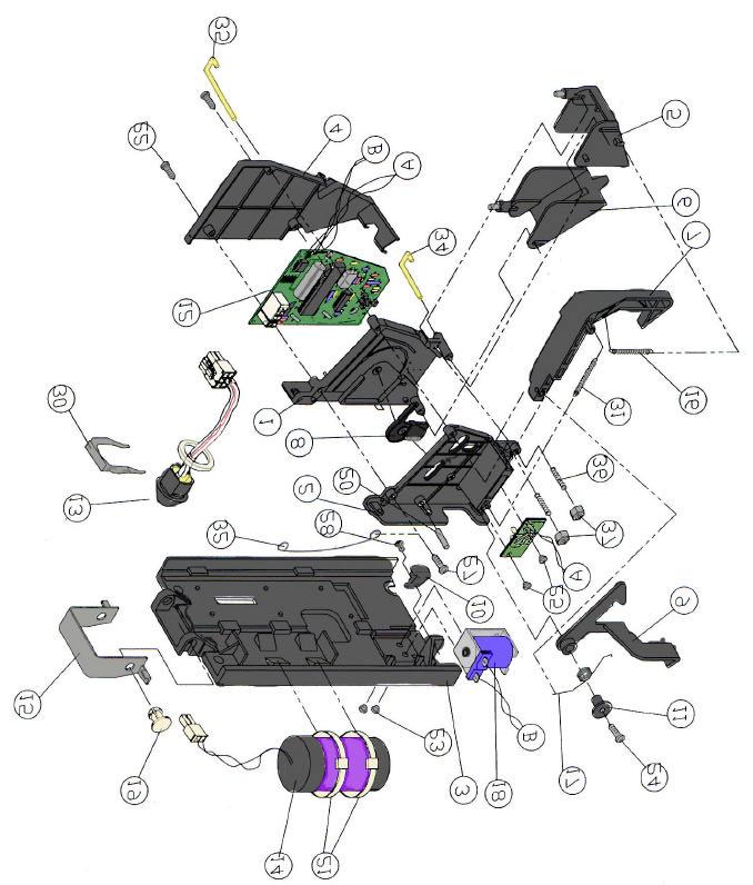
2 Contents Page SUPER WAND OVERVIEW 2 BUFFER BOX 3 ST-100 INSTALLATION 4 SETTING UP AND INITIALIZING 6 ERROR CODES 7 MAINTENANCE 9 TROUBLESHOOTING 12 PARTS DIAGRAM 14 PARTS LIST 15 1

3 Super Wand Overview Audit Wand The Audit Wand provides the communication link between the Data Wizard and the computer. The Audit Wand conveys the current edition, time/date and price to the Data Wizard. At the same time, it extracts sales information from the ST- 201 Data Wizard for transfer to the computer. A Wand can hold data for more than 10,000 sales. An Audit Wand is carried by the delivery driver. It should be carried in the holster to protect it from damage. The Audit Wand is waterresistant but not waterproof. It should not be left in the sun/heat nor should it be left outside in cold weather. The same care should be taken with a Wand as with a cell phone. Collection Wand A collection Wand is used to collect cash data from the Data Wizard. Maintenance Wand The Maintenance Wand is used to set up new Data Wizard locations and to assist with troubleshooting. When docked, the Wand will display an error code if the ST-201 Data Wizard is not working properly. Refer to page 7 of this manual and the Super Wand Manual for error code explanations and Wand functions. 2

4 Download Buffer Box The buffer box is usually located at the newspaper distribution point. The buffer uploads current date, time, edition and price to the Wands. At the same time, it downloads the sales information collected by the Wands. It stores the sales data until it is downloaded by the computer. Delivery personnel need to dock their Wands to the buffer box each day before delivering their route or running maintenance routes to ensure that the Data Wizards are initialized with the current edition, date and time. The buffer box can store several days, sometimes weeks, of data in the event that it cannot be downloaded on a daily basis. A UPS with surge protector should be used with the buffer box to protect against power spikes and power outages. 3


5 ST-100 Installation The ST-100 Data Wizard is designed for easy retrofit into newsracks. The ST-100 model is specifically designed to replace stacker type mechanical coin devices. Tools Required: Medium size pliers Phillips screwdriver Flat blade screwdriver Nut driver 1. Open the paper door and the rack head. Remove the existing mechanism and keyswitch assembly. Retain the spring clip from the keyswitch. Make sure the front of the rack head is not bent. It may be necessary to straighten it before proceeding. 2. Bend the stationary latch slightly to the right to ensure that it does not rub on the plastic coin doors. 3. Insert the datalink through the keyswitch hole from the front of the rack head. Align the datalink so the magnet (visible from the back) in the nose is facing toward the center of the rack. Position the magnet towards the top on side-by-side racks. Use the spring clip to fasten the datalink in place. 4. Remove the nylon tab from the coin path housing. This tab holds the coin damper stationary during transport. 5. Mount the ST-100 on the four studs in the rack head. Lock it into place with the lock-in bracket and wireform. 6. Make sure nothing interferes with the coin doors, the coin deflector, or other mechanical functions. 7. The front side of the coin return slide should fit in between the lower projections of the coin deflector. If the slide does not fit correctly, bend the slide edge to position it properly. 4


6 8. The coin return button should have a small amount of play before contacting the coin return lever. The return catch must not contact the return door pin when the return button is not pushed. If it does, inspect the coin return linkage. 9. Open and close the rack door to check that the door tongue operates smoothly with the Data Wizard. The right side of the door tongue must hold the coin retain door (door nearest the front of the head) fully closed. Make sure the tongue does not interfere with the coin deflector. 10. Plug the datalink connector into the 6-pin housing on the circuit board. 11. Close the rack head before testing. The datalink is light sensitive, especially from the back. Bright light from the back or front of the data link can interfere with communication. 12. Using a Maintenance Wand set the Mech ID and initialize the Data Wizard. Initializing the Data Wizard with a Maintenance Wand sets the current edition and price and eliminates the need to carry an Audit Wand. See the section on Setting up and Initializing the ST-100 for more detailed instructions on setting up the Data Wizard. 13. With the rack door and head closed, check the operation of the ST-100 Data Wizard with coins. 14. Drop enough coins into the coin slot to equal the set price and verify that the rack opens. Open and shut the paper door. 15. Insert another coin (not a penny) that is less than the set price and pull on the door to verify that it does not unlock on less than the set price. 16. Press the coin return button to return the coin. Activating the coin return clears the current cash total. 17. Repeat steps until satisfied that the Data Wizard is recording sales and cash correctly. 5

7 Setting Up and Initializing the ST-100 Data Wizard Clearly mark the inside of the rack head with a permanent marker or a label with the number assigned to this location. This is the Counter/Dealer number that this location has been assigned in the SC2000 database. This number must also be programmed into the Data Wizard with the Maintenance Wand or Audit/Maintenance Wand. This number can be up to five digits in length with the maximum number being Leading zeros will be stripped off. 1. Reset the Data Wizard by shorting the two Reset tabs at the top of the circuit board, together with a flat blade screwdriver or similar object. The tabs on older ST-100s will be labeled TP1 and TP2 instead of Reset. Newer models may have a blue Reset button instead of solder tabs. 2. To set the Mech ID, press the Function button on the Wand. Scroll through the functions with the Enter key until Set Mech ID is displayed on the Wand LCD. Press the Select key. The Wand will prompt for the Mech ID. Enter the number assigned and press the Enter key. The Wand will emit a continuous beep. Dock the Wand to the ST-100 Data Wizard. The solenoid will fire resulting in an audible click. 3. Reset the ST-100 a second time as described in step To set the edition and price, press the Function button on the Wand. Scroll through the functions with the Enter key until Init Mech is displayed on the Wand LCD. Press the Select key. The Wand will emit a continuous beep. Dock the Wand to the ST-100 Data Wizard. The solenoid will fire resulting in an audible click. To set edition and price with an Audit/Maintenance Wand, simply dock the Wand to the ST-100 Data Wizard. 5. Check the ID programmed into the ST-100 Data Wizard ID by docking the Maintenance Wand to it. The ID number will be displayed on the Wand LCD. To check ID with an Audit/Maintenance Wand, press the Function button on the Wand. Scroll through the functions with the Enter key until Display Mech ID is displayed on the Wand LCD. Press the Select key. The Wand will emit a continuous beep. Dock the Wand to the ST-100 Data Wizard. The solenoid will fire resulting in an audible click. The ID number will be displayed on the Wand LCD. 6. Open then close the door. Test the ST-100 Data Wizard with coins to ensure that it reads and counts all coins. 6
8 Error Codes When the Wand is docked, the Data Wizard runs through a self check sequence. If a condition returns an error, an error code is displayed on the Wand LCD. ERROR COMM indicates inability of the Wand to communicate with the Data Wizard. The Wand may have been pulled away before communication was complete. Re-dock the Wand. If the error persists, clean the nose of the Wand with a soft cloth or Q-tip to remove dirt. Datalinks are sensitive to bright light. Shield the datalink from light striking it from both the front and the rear. ERROR COINDOOR could indicate that the coin retain door is not closed properly. It could also suggest that the accept door magnet is missing. Check for damage and/or foreign materials, including coins, that may be preventing the door from closing properly. Verify that the magnet on the retain door is place. It is also possible that the magnet has lost strength and may need replaced. The accept reed switch on the circuit board may be broken. ERROR COIN DET suggests that the ST-100 is not detecting coins. This is indicated by the coin detect reed switch being closed, usually by the magnet on the damper. Make sure there are no foreign materials in the coin path that may be holding the damper down. Spread the counter housings and clean with compressed air. Remove any obstructions. It may be necessary to take the counter housing apart and clean the coin path. Do not use a screwdriver or other sharp object to remove debris. This type of tool may cause scratching in the coin path, causing objects to become lodged more easily. Verify that the damper moves freely and that the damper magnet is in place. The damper or magnet may need to be replaced. The coin detect reed switch on the circuit board may be broken. ERROR SLUG: indicates that the slug detect reed switch is open. This switch is normally held closed by the magnet on the counter housing. This magnet is held in place by a spot of hot melt glue. If a ferrous slug passes the switch, it breaks the magnetic field and opens it. If several slugs are inserted into the coin path, the switch may become stuck open. Run a valid coin through the ST-100 to close a switch that is stuck open. Make sure the house magnet is in place. Try pushing the magnet in or pulling it out slightly to adjust it. The slug detect reed switch on the circuit board may be broken. 7
9 ERROR COIN RET indicates an active coin return reed switch. The coin return reed switch is activated by the magnet on the coin return door, usually when the coin return button is pushed. Check for foreign material, including coins that may prevent the coin return door from closing properly. Make sure the coin return button is not partially pushed in. Make sure that the torsion and extension springs that are attached to the return door and return lever are functioning properly. ERROR PHOTOLED indicates that there is a problem reading coins. Coins are read by shining an infrared light across the coin path through tiny holes in the housing. This light is detected by phototransistors on the circuit board. If there is an obstruction in the coin path or the tiny holes are blocked, the phototransistors will not detect the infrared light. This error can be also be caused by a faulty LED circuit board or faulty phototransistors on the main circuit board. Make sure there are no foreign materials in the coin path that may be blocking the photo sensors. Spread the counter housings and clean with compressed air. Remove any obstructions. It may be necessary to take the counter housing apart and clean the coin path. Do not use a screwdriver or other sharp object to remove debris. This type of tool may cause scratching in the coin path, causing objects to become lodged more easily. Replace the LED circuit board. ERROR TIMEOUT means that the Wand has timed out and needs to be docked to the buffer. The buffer sets a timeout period in the wand. Timeout periods will vary depending on site configuration. Each wand must be docked to the buffer within the timeout period or it will no longer communicate with the Data Wizards. Data will not be lost in the Wand if it times out. 8
10 Routine Maintenance Occasional cleaning of the coin path and door assemblies will prevent most problems. Clean the counter housing twice a year or as required. Clean with compressed air or disassemble the housing and wipe with a Windex and a soft cloth. The coin box assembly should open freely when pressed down. Replace with new doors if needed. Visually inspect the ST-100 Data Wizard for broken or missing parts. With the rack head open, insert enough coins to fire the solenoid. Watch the trip lever to ensure that it falls completely and does not catch on the door tongue. Diagnosis and Repair Field Repairs: When repairing an ST-100 in the field, carry the following items with you. Maintenance Wand to check for the self diagnostic error codes Spare ST-100 in the event of un-repairable damage Damper Retain door Return catch Torsion spring Return lever Trip lever with small pushpin 3/8" and 1/4" nut drivers #2 Phillips screwdriver Needle nose pliers Reverse action tweezers If the Data Wizard is able to communicate with a Wand, the data may be read out of it and copied back into it or into a replacement after repair and testing. Using a Maintenance Wand, press the Function key. Scroll through the functions, using the Enter key until the LCD displays READ DATA. Press the Select key and the wand will begin to beep. Dock the Wand to the Data Wizard. The Wand will chirp as it reads the data out of the Data Wizard into Wand memory. This procedure does not erase the data from the Wizard; it only makes a copy of it into Wand memory. This data will remain in Wand memory until it is overwritten by again reading data from a Data Wizard. This function allows the Data Wizard to be repaired and tested without creating extraneous data. It also allows the data to be written into another Data Wizard if the damaged one needs to be replaced. 9
11 Dock the Maintenance Wand to the rack and monitor error codes. The wand should display the Mech ID#. If it does, try to open the rack door. If the door opens, dock the wand again while the door is open to check the coin door reed switch and magnet. If the reed switch is working properly the Data Wizard should return ERROR COIN DOOR on the Wand. If not, the reed switch or the magnet is not working. Replace these parts and re-test. If door does not open, open the rack head and dock the wand again. Watch the trip lever. The solenoid fire should fire and the trip lever should fall. If the solenoid does not fire, check the wire connections. If the solenoid does fire, but the trip lever does not fall, there may be burrs on the pushpin, the return catch may be broken, the coin return lever may be stuck or the door tongue may not be properly adjusted. If the rack door opens with the Wand but does not return an error code, test the ST-100 with coins. If after inserting enough coins, the rack will not open, replace the damper and coin test again. If the rack still does not open, the ST-100 will need the coin detect reed switch on the circuit board replaced. (S4) The ST-100 should be checked for broken or missing parts. Before leaving the rack, make sure the price setting is correct. If the ST-100 was replaced, make sure that the Mech ID# has been set and the ST-100 initialized to avoid any loss of data for that location. Write the data from the Wand memory into the repaired or the newly installed Data Wizard. This will overwrite data from testing and replace it with the data that the ST-100 initially contained. Press the Function key and scroll through the functions by pressing the Enter key until WRITE DATA is displayed on the Wand LCD. Press the Select key. The Wand will begin to beep. Dock the Wand to the Data Wizard. The Wand will chirp as it overwrites existing data in the Data Wizard with the data in Wand memory. In circumstances where the circuit board on the Data Wizard prevents communication, data will be unrecoverable. 10

12 Removing the ST-100 from the Rack With the rack door open, the coin retain door hangs open. The triangular ramp can hang through the tongue slot on the face of the rack. If the ST-100 is pulled upward during removal, the ramp may be caught in the slot and broken off. The ST-100 should always be removed with the rack door closed. Door Open Door Closed 11
13 Troubleshooting Problem: The Newsrack Will Not Open With the Wand Solution: Turn the wand clockwise or counter-clockwise in the hand while docking for a better communication position. If the rack still does not open, open the rack head and visually inspect the datalink and cable. Make sure that the cable is securely connected to the circuit board. Replace the datalink if damage is detected. Ensure that the front coin door closes completely when the door tongue is pushed against it. If the coin door doesn t close completely, the trip lever will not push the door tongue down far enough to open the door. The door tongue may need to be adjusted. The ST-100 may not communicate if bright sunlight or headlights are shining directly on the datalink. Shade the datalink nose with your hand for a few seconds and retry communication. Make sure that the coin return door closes completely. If the coin return lever sticks and does not slide smoothly, the door may not close, resulting in inability to communicate. Check the rack for physical damage that could cause the door to malfunction. Problem: The Rack Will Not Open With Coins. Solution: Check for damage to the rack. Open the rack and look for jammed coins around the coin doors. Make sure that the tongue does not push on the coin deflector. This can cause the coins to jam in the coin doors. If the rack has a gum stopper, bend it down to prevent interference with the coin door. Make sure that the lock bar does not interfere with the coin return lever. Insert enough coins into the ST-100 to equal the current price. The solenoid should fire. If the solenoid does not fire, check the battery voltage. If the battery voltage is acceptable, the problem likely lies with either the coin detect or coin read circuit or components. 12

14 Problem: The Return Catch Prevents the Trip Lever From Falling and the Door Won t Open Solution: The return catch is designed to touch the trip lever when it is in the up position if the return button is pushed in. If the return lever does not return all the way forward, the return catch will remain down and the foot may bind against the trip lever. Look for anything that may bind the trip lever such as a rough edge, a loose pushpin, binding coin return button or dirt. Problem: The Coin Return Button Does Not Release the Coin Door Solution: Straighten the rack face if it is bent. Replace the short coin return button with a longer one. Bend the stationary latch about 10 degrees to the right from the rack. 13
15 14
16 Item Part Part 2005 # Number Description Price 1 & Counter Housing Set, Right & Left with Magnet $ Mounting Plate $ Cover Deflector $ & & 23 Return/Retain Door Set with magnet $ Return Lever $ Damper With Magnet $ Return Catch $ Trip Lever Assembly, Includes # 28 $ Bushing $ Main PCB/LED Board Assembly $ B-301 Keyswitch, 3 Position, clear $ B-311 Keyswitch, 3 Position, clear $ DataLink for ST-100 $ Lithium 'D" Cell Battery Replacement Kit $ Lock-in Bracket $ Extension Spring (Light) $ Torsion Spring $ Solenoid $ Push-in Fastener, Large, (x2) $ House magnet $ Cable Tie, Large, (x2) $ Screw, # 8 x 5/8, (x2) Type 25 PPH $ Screw, machine, # 6-32 x 3/16, (x2) $ Screw, Type 25, # 6 x 3/4 $ Screw, Type 25, # 6 x1/4, (x2) PPH $ No Part Screw, Type 25, # 6 x3/8 PPH $ Push-in Fastener (Small) $ No Part Spring Clip $ Extension Spring (Heavy) $ Lock-in Wireform $ No Part Hook, Short $ Hook, Long $ Compression Spring (x2) $ ESNA Nut, # 4-40 (x2) $ Return Lever Insert $0.45 Misc Metric e-ring for coin return button $0.35 Misc DataLink for ST-100 upgrade $13.75 Misc No Number B-301, B-311, or B-326 key $
ST-810 plus-mech User Manual
 ST-810 plus-mech User Manual Page 1 of 7 The ST-810 plus-mech is designed to fit into your current TK style newsrack. The ST-810 plusmech accepts nickels, dimes, quarters and dollar coins. It will not
TRITON ERROR CODES ERROR CODE MODEL SERIES DESCRIPTION RESOLUTION
 0 8100, 9100, 9600, 9610, 9615, 9640, No errors 9650, 9700, 9710, 9705, 9750, RL5000 (SDD),RL5000 (TDM), RT2000, 9800, MAKO, SuperScrip 1 9615 Unsolicited note channel 1 2 9615 Unsolicited note channel
Maintenance Information
 Form 16575334 Edition 1 April 2005 Electric Screwdrivers EL, EP and ET 34V DC Series Maintenance Information Save These Instructions WARNING Maintenance procedures have the potential for severe shock hazard
Installation Instructions Z-Gate Shifter
 Installation Instructions Z-Gate Shifter Part Number 80681 1998, 2001 by B&M Racing and Performance Products The B&M Z-Gate shifter can be used in vehicles equipped with most popular three speed automatic
Instructions for repairing the F-Body Hatch Pull-Down Unit By Lon Salgren (ls90rs)
") Instructions for repairing the 1986-87 F-Body Hatch Pull-Down Unit By Lon Salgren (ls90rs) Lonsal@adelphia.net CAUTION: Completely read and understand the instructions before proceeding. There are some
Instructions for repairing the 1986-87 F-Body Hatch Pull-Down Unit By Lon Salgren (ls90rs) Lonsal@adelphia.net CAUTION: Completely read and understand the instructions before proceeding. There are some
DARMAN. ENDURA II Cloth Towel Cabinet Product Guide. Manufacturing Company, Inc Lincoln Ave., Utica, NY 13502
 ENDURA II Cloth Towel Cabinet Product Guide Page 2, 3 4, 5 6, 7 8, 9 10 11 12 Parts Covered Hood Assembly Mechanism Back Assembly Bin and Towel Guide Service Bulletin - Roller Warranty and Maintenance
Installation Instructions. QuickSilver Shifter. Fits: GM, Ford, Chrysler Transmissions See Application Guide for Specific Applications Part # 80683
 Installation Instructions QuickSilver Shifter Fits: GM, Ford, Chrysler Transmissions See Application Guide for Specific Applications Part # 80683 WORK SAFELY! For maximum safety, perform this installation
Auto-Lift Operating System
 Installation Instructions Parasol Cellular Shades Auto-Lift Operating System CONTENTS Getting Started: Product View... 1 Tools and Fasteners Needed... 2 Installation: Installation Overview... 3 STEP 1
Installation Instructions Right Hand Drive Megashifter
 Installation Instructions Right Hand Drive Megashifter Part Number 80685 1995, 2001, 2006, 2010 by B&M Racing & Performance Products The B&M Right Hand Drive Megashifter is designed specifically for vehicles
Light Truck MegaShifter
 Installation Instructions Light Truck MegaShifter The B&M Light Truck Megashifter shifter is designed to be used in most light trucks equipped with most popular three speed or four speed automatic transmissions.
Hurst VMATIC3 INSTALLATION
 FORM 159 8530 07/12 Hurst VMATIC3 3-Speed & 4-Speed Automatic Shifter Catalog #3838530 2012 by Hurst Performance The Hurst Vmatic3 shifter can be used in vehicles equipped with most popular three speed
Installation Instructions StarShifter
 Installation Instructions StarShifter Part Number 80675 2000 by B&M Racing & Performance Products LLC The B&M StarShifter can be used in vehicles equipped with most popular three speed automatic transmissions.
Installation Instructions Megashifter
 Installation Instructions Megashifter The B&M Megashifter shifter can be used in vehicles equipped with most popular three speed or four speed automatic transmissions. Your B&M Megashifter comes equipped
Conflicts: Vehicles without a sunroof Vehicles with a single sunroof
 Toyota Sienna (Dual Sunroof) 2011-10.2 Overhead Video Part Number: 00016-00110 00016-00110-17 Fit Kit 00016-00120 00016-00120-17 Fit Kit Accessory Code: ED5 Conflicts: Vehicles without a sunroof Vehicles
Installation Instructions Sport Shifter
 The B&M Sport Shifter can be used in vehicles equipped with most popular three speed or four speed automatic transmissions. It is equipped with neutral safety and backup light switches, transmission brackets
Troubleshooting. This section outlines procedures for troubleshooting problems with the operation of the system:
 Troubleshooting This section outlines procedures for troubleshooting problems with the operation of the system: 4.1 System Error Messages... 4-2 4.2 Prep Station Troubleshooting... 4-6 4.2.1 Adapter Not
Installation Instructions Street Bandit Shifter
 Installation Instructions Street Bandit Shifter Part Number 80797 (see www.bmracing.com for the latest technical product information) 2006, 2000 by B&M Racing and Performance Products The B&M Street Bandit
Oreck Magnesium Series Service Manual. The Oreck Manufacturing Company
 Oreck Magnesium Series Service Manual The Oreck Manufacturing Company 08/2012 10/2011 The Oreck Manufacturing Company Contents Covering all Magnesium Upright Models Including: LW100, LW125, LW1000, AND
GrilleGuy.com, LLC. Installation Instructions and Care Guide : Toyota Tacoma Grille UPPER GRILLE
 Installation Instructions and Care Guide : 2001 2004 Toyota Tacoma Grille Thanks again for purchasing your custom grille insert from GrilleGuy.com. The following are some general guidelines that will simplify
TCI FastGate Shifter Installation Instructions
 151 INDUSTRIAL DRIVE ASHLAND, MISSISSIPPI 38603 http://www.tciauto.com TELEPHONE: 662-224-8972 FAX LINE: 662-224-8255 E-MAIL: tech@tciauto.com TCI 616541 FastGate Shifter Installation Instructions The
Installation Instructions QUICKSILVER CONSOLE SHIFTER Fits: Chevelle / El Camino
 WORK SAFELY! For maximum safety, perform this installation on a clean, level surface and with the engine turned off. Place blocks or wedges in front of and behind both rear wheels to prevent movement in
Tooling Assistance Center
 Safeguards are designed into this application equipment to protect operators and maintenance personnel from most hazards during equipment operation. However, certain safety precautions must be taken by
Detroit Speed, Inc. Electric Headlight Door Kit Corvette P/N: &
 Detroit Speed, Inc. Electric Headlight Door Kit 1968-82 Corvette P/N: 122006 & 122007 The Detroit Speed Inc. Electric Headlight Door Kit replaces the stock vacuum actuated system on all 1968-82 Corvettes.
Installation Instructions Unimatic Shifter
 Installation Instructions Unimatic Shifter Universal Shifter for Automatic Transmissions Part Number 80775 2010, 2000 by B&M Racing & Performance Products The B&M Unimatic is a universal shifter that will
Photo 1. Shift pattern gate plate
 Installation Instructions MAGNUM GRIP STREET BANDIT SHIFTER Fits: GM, Chrysler, and Ford Automatic Transmissions See Application Guide for Specific Vehicles Catalog # 81050 WORK SAFELY! For maximum safety,
Maintenance Information
 16573370 Edition 2 February 2014 Air Grinder 99V Series Maintenance Information Save These Instructions Product Safety Information WARNING Failure to observe the following warnings, and to avoid these
GENESIS KIT for Rowe. INSTALLATION: BC12R, 1400 Special tools needed drill and a 5/32 bit
 Page 1 of 5 GENESIS KIT for Rowe INSTALLATION: BC12R, 1400 Special tools needed drill and a 5/32 bit THE COIN DETECTOR LIGHT(S) ON THE COIN DISPENSER FRAME NEED TO BE THE NEWER RED LED TYPE. IF YOU HAVE
TrailerTail does not open at all (one or both sides) TrailerTail does not latch closed... 5
 TrailerTail does not latch closed... 5") This is a step-by-step guide to diagnose and repair the most common AutoDeploy field issues. If at any time you would like direct phone support, please call STEMCO Customer Support at 888-283-8245 x2.
This is a step-by-step guide to diagnose and repair the most common AutoDeploy field issues. If at any time you would like direct phone support, please call STEMCO Customer Support at 888-283-8245 x2.
PD10-M-RIM INSTALLATION INSTRUCTIONS. The PD10-M-RIM is a storefront grade 1 exit device equipped with motor drive latch retraction.
 PD10-M-RIM INSTALLATION INSTRUCTIONS The PD10-M-RIM is a storefront grade 1 exit device equipped with motor drive latch retraction. Retrofits Doromatic 1790 & First Choice 3790. B. G. A. C. D. E. F. PD10-M-RIM
TERMINATOR User Manual
 TERMINATOR User Manual TERMINATOR User Manual Table of Contents Section Page 1 2 3 4 5 6 7 8 9 10 11 12 13 14 15 16 17 18 19 20 21 Introduction Safety Precautions Features and Benefits Overview of the
Conflicts: Vehicles with no sunroof or dual sunroof
 Toyota Sienna (Single Sunroof) 2012-8.5 Overhead Video Part Number: 00016-00125 -11 Accessory Code: ED9 Conflicts: Vehicles with no sunroof or dual sunroof General Applicability: 2011 Sienna SMR Kit Contents:
Service Manual Gulf Stream Electronic Full Wall Slide Systems
 Service Manual Gulf Stream Electronic Full Wall Slide Systems CONTENTS Page Before you operate the slide system 2 Operating Instructions 3 Preventive maintenance 3 Manually overriding your slide system
Customer Name: Serial Number: Y-Axis Stall
 Technician Name: Date: Technician Name: Date: Customer Name: Serial Number: Y-Axis Stall Issue Explanation and Background Each drive motor on the machine (the x, y and z axes motors) has a sensor called
Auto Sentry-eXP Maintenance. Revised 12/21/07
 Auto Sentry-eXP Maintenance Revised 12/21/07 Maintenance Procedures for Auto Sentry exp Bill Dispenser Credit Card Reader Bill Acceptor Bill Dispenser Maintenance Bill Dispenser Problem / Cause Bill Dispenser
Installation Instructions Console Megashifter
 Installation Instructions Console Megashifter 1968-1969 Camaro Part Number 81035 This B&M Megashifter is designed to fit in the console of a 1968-1969 Chevrolet Camaro. In 1968, these vehicles were equipped
Installation Instructions Pro Stick Shifter
 Installation Instructions Pro Stick Shifter Part Number 80701, 80702 & 80706 2012, 2010, 2008, 2001, 1998 by B&M Racing and Performance Products The B&M Pro Stick shifter #80701 and #80706 comes equipped
Maintenance Guide AZTEC BNF-2000 BILL ACCEPTOR PRIMARY COMPONENT PARTS
 AZTEC BNF-2000 Bill Acceptor Maintenance Guide October, 2007 October, 2007 Maintenance Guide JCM is a registered trademark of JCM American Corporation. All other product names mentioned herein may be registered
Installation Instructions Unimatic Shifter
 Installation Instructions Unimatic Shifter Universal Shifter for Automatic Transmissions Part Number 80775 2000 by B&M Racing & Performance Products LLC The B&M Unimatic is a universal shifter that will
MANUAL VERSION FEBRUARY
 MANUAL VERSION FEBRUARY 2008 MAINTENANCE AND TROUBLESHOOTING Quick Troubleshooting: WARNING For your safety and to reduce risk of damage to your game read the Important Safety Information in Chapter 1-2
Do not have any open flame or heat sources close to the installation
 March 6, 2017 IS# 791 Page 1 of 16 Thank you for purchasing a Transfer Flow, Inc. 50-gallon replacement fuel system for your 2011-16 Ford diesel short bed pickup. This system will fit any 2x4 or 4x4 crew
MC-CRX. Bill Acceptor Card Reader Combo. Operation & Service Manual
 MC-CRX Bill Acceptor Card Reader Combo Operation & Service Manual TABLE OF CONTENTS SECTION 1: GENERAL INFORMATION Introduction...4 Features...4 For Records...4 After Unpacking...4 Naming Convention...5
Technical Support (707)
") Installation Instructions UNIMATIC SHIFTER Fits: GM, Powerglide, Ford and Chrysler Transmissions See Application Guide for Specific Vehicles Catalog # 80775 WORK SAFELY! For maximum safety, perform this
Installation Instructions UNIMATIC SHIFTER Fits: GM, Powerglide, Ford and Chrysler Transmissions See Application Guide for Specific Vehicles Catalog # 80775 WORK SAFELY! For maximum safety, perform this
Shotgun Double Barrel HPFP install guide
 Shotgun Double Barrel HPFP install guide Thank you for your purchase of the VTT Shotgun Double Barrel HPFP upgrade! First thing to do when you open your box is to make sure all parts are in their respective
BASIC TROUBLE SHOOTING (PERFECTPASS FOR MECHANICAL ENGINES) How PerfectPass Works
 How PerfectPass Works") BASIC TROUBLE SHOOTING (PERFECTPASS FOR MECHANICAL ENGINES) How PerfectPass Works Through the in-dash display the driver sets the desired boat speed or engine RPM depending upon which mode of operation
BASIC TROUBLE SHOOTING (PERFECTPASS FOR MECHANICAL ENGINES) How PerfectPass Works Through the in-dash display the driver sets the desired boat speed or engine RPM depending upon which mode of operation
Technical Service BULLETIN
 Technical Service BULLETIN December 6, 2006 Title: Models: 98 03 Sienna BO027-06 BODY TSB UPDATE NOTICE: The information contained in this TSB supercedes TSB No. BO012-01. TSB No. BO012-01 is now obsolete
Z-Gate Universal Shifter
 Installation Instructions Z-Gate Universal Shifter Fits: GM, Ford, Lincoln and Chrysler Transmissions See Application Guide for Specific Applications Part #80681 Rev 06/01/2018 WORK SAFELY! For maximum
RS-110 Rainfall Sensor Installation Guide
 RS-110 Rainfall Sensor Installation Guide for XR440 and XR5 Data Loggers September 2015 Revision 1.1 1 Disclaimer The following warranty and liability disclaimer apply to this product. PACE SCIENTIFIC
Wheel Angle Sensor Kit Installation
 Wheel Angle Sensor Kit Installation Item Component Part Number Qty 1. WAS Bracket Kit 200-0247-02 1 2. WAS Assembly Kit 200-0468-01 1 3. Instruction Guide 602-0401-01 1 602-0401-01-A Overview Always shut
M-9603-SVT mm Cold Air Kit w/premium Calibration INSTALLATION INSTRUCTIONS
 Please contact the Tech Line for the most current instruction information (800) 367-3788.!!! PLEASE READ THE FOLLOWING INSTRUCTIONS CAREFULLY PRIOR TO INSTALLATION!!! OVERVIEW: This kit is designed for
2" - 24" OS Series Butterfly Valves. Operation and Maintenance Manual. Job Name: Contractor: Date:
 s Operation and Maintenance Manual Job Name: Contractor: Date: Document #: IOM Revision Date: 10/2/2016 SAFETY MESSAGES All safety messages in the instructions are flagged with an exclamation symbol and
LIPPERTCOMPONENTS, INC.
 LIPPERTCOMPONENTS, INC. SCHWINTEK INWALL SLIDEOUT SYSTEM OPERATION AND SERVICE MANUAL Contents I. Controls 1-1 System components 1 1-1A versions C1 & C2 2 1-2 Motor wiring harness connections 3 1-3 Extend
Troubleshooting. Pull Type Clutches - Poor Release
 Troubleshooting Pull Type Clutches - Poor Release Complaint Possible Causes Corrective Action Poor Release Intermediate plate sticking on drive lugs due to cocked drive pins (AS and EP 1402 only) (see
TOYOTA TUNDRA TVIP V4 REMOTE ENGINE STARTER (RES)
") Preparation Part Number: 08586-OC910 Conflicts Do not install into vehicles without RKE systems. Recommended Sequence of Application Item # Accessory 1 TVIP/RES Any TVIP or RES system 2 XM Radio NOTE:
Preparation Part Number: 08586-OC910 Conflicts Do not install into vehicles without RKE systems. Recommended Sequence of Application Item # Accessory 1 TVIP/RES Any TVIP or RES system 2 XM Radio NOTE:
Service/Installation Manual Full Wall Slide Systems CONTENTS. 82-S0379 Rev 3. Page. Before you operate the slide system 2
 Service/Installation Manual Full Wall Slide Systems CONTENTS Page Before you operate the slide system Operating instructions Preventive maintenance Manually overriding your slide system 0" Stroke system
Installation Instructions Table of Contents
 Installation Instructions Table of Contents Pre- Installation of Garage Storage Lift 2 Layout the Garage Storage Lift 3 Installing the strut Channels 3 Install the Drive Assembly 5 Install the Drive Shaft
PRO RATCHET UNIVERSAL SHIFTER
 Installation Instructions PRO RATCHET UNIVERSAL SHIFTER Fits: GM, Ford and Chryslers w/automatic Transmission See Application Guide for Specific Vehicles Catalog # 80842 WORK SAFELY! For maximum safety,
9-I DUETTE SHADES POWERVIEW MOTORISATION
 SECTION: 9-I DUETTE SHADES POWERVIEW MOTORISATION 9-I DUETTE SHADES POWERVIEW MOTORISATION Product View Installation Brackets End Cap Manual Control Button Fabric-Covered Headrail Bottom Rail Battery Wand
Merkur Scorpio Odometer Repair Instructions
 www.odometergears.com Merkur Scorpio Odometer Repair Instructions http://www.bitsprings.com/gearinst.pdf Please read through these instructions completely once before proceeding. It is important to understand
HARNESS KIT F INSTALLATION INSTRUCTIONS. Vehicle: Mazda RX-8 Parts number F CFZ (ipod integration module) C9F4 V6 029 (Harness Kit F)
 C9F4 V6 029 (Harness Kit F)") GENUINE ipod INTEGRATION MODULE HARNESS KIT F INSTALLATION INSTRUCTIONS Vehicle: Mazda RX-8 Parts numberf197 79 CFZ (ipod integration module) C9F4 V6 029 (Harness Kit F) Thank you for purchasing a genuine
GENUINE ipod INTEGRATION MODULE HARNESS KIT F INSTALLATION INSTRUCTIONS Vehicle: Mazda RX-8 Parts numberf197 79 CFZ (ipod integration module) C9F4 V6 029 (Harness Kit F) Thank you for purchasing a genuine
CALIFORNIA TRIMMER MOWER MAINTENANCE MANUAL
 CALIFORNIA TRIMMER MOWER MAINTENANCE MANUAL 2 Table of Contents Section 1: General Information Page Handle Assembly Instructions 4 Maintenance All Models 6 Oil Change Procedures All Models 9 Height Adjustment
QUADBOSS UTV STRAIGHT PUSH TUBE OWNER S MANUAL
 PAGE of 6 PART #938 QUADBOSS UTV STRAIGHT PUSH TUBE OWNER S MANUAL This owner s manual covers all aspects of your new push tube including assembly, replacement parts, installation, warranty, and troubleshooting.
IMPORTANT! Remote Control Instructions
 Remote Control Instructions FOR New Tarp Remote Control Installation Use these in place of the rocker switch and solenoid section of instructions in your roll tarp owner s manual. FOR Existing Electric
DEMON CARBURETOR MANUAL CHOKE KIT #421441
 DEMON CARBURETOR MANUAL CHOKE KIT #421441 CHOKE INSTALLATION INSTRUCTIONS LIT703 This manual choke kit is designed to be used on any Demon Carburetor with a choke tower. This covers the Road Demon Jr.
Marsh Shipping Supply Co. LLC. Marsh TD2100 Electric Taper Technical Manual
 Marsh Shipping Supply Co. LLC Marsh TD2100 Electric Taper Technical Manual 2 A wall-socket must be close to the product and readily accessible. The overall system is protected against overload by the branch
Battery-Powered Motorized System
 Installation, Operation and Care Instructions Battery-Powered Motorized System CONTENTS Getting Started: Product View... 1 Tools and Fasteners Needed... 2 Installation: Installation Overview... 3 STEP
INSTALLATION AND CUSTOMER CARE INFORMATION 80 SERIES & 90 SERIES TREATMENT STATIONS
 INSTALLATION AND CUSTOMER CARE INFORMATION 80 SERIES & 90 SERIES TREATMENT STATIONS Customer Service and Technical Support: 8:00 AM to 5:00 PM central (M-Th) 8:00 AM to 4:30 PM central (Fri) Phone: 800-257-7407
24-48 HP250II Butterfly Valve. Operation and Maintenance Manual. Job Name: Contractor: Date: Document #: 2448HP250OOOM Revision Date: 1/10/11
 24-48 HP250II Butterfly Valve Operation and Maintenance Manual Job Name: Contractor: Date: Document #: 2448HP250OOOM Revision Date: 1/10/11 SAFETY MESSAGES All safety messages in the instructions are flagged
Sunroof Repair. Sunroof Repair TSB. The sunroof repair kit available for the J30 is part number Y20. See images at bottom of document.
 Sunroof Repair This document is the text/images from the TSB (technical service bulletin) issued by Infiniti concerning the repair procedure for sunroof issues. Be advised that this is a LARGE, TIME-CONSUMING
Firehawk Second Stage Regulator Fire Service
 Firehawk Second Stage Regulator Fire Service MAINTENANCE AND REPAIR TAL 1701 (L) Rev. 2 MSA 2017 Prnt. Spec. 10000005389(I) Mat. 10147454 Doc. 10147454 TAL 1701 (L) Rev. 2-10147454 2 NON-CBRN FIREHAWK
INTEGRATION MODULE HARNESS KIT A4, F4
 GENUINE INTEGRATION MODULE HARNESS KIT A4, F4 INSTALLATION INSTRUCTIONS Vehicle: Mazda MX-5 Parts numberbbm2 79 CFZ (ipod integration module) C9FA V6 029 (Harness Kit A4) C9FB V6 029 (Harness Kit F4) Thank
Upper Class Grille Main grille INSERT - #54127 / #54131 / #54133 / #51127 / #51131 / 51133
 Parts included (1) - Main Full Opening - Polished - Part #54127 OR 1 Bar - Polished - Part #54131 OR 2 Bar - Polished - Part #54133 OR Full Opening - Black - Part #51127 OR 1 Bar - Black - Part #51131
TOYOTA RAV4 w/smart 2009 TVIP V4 PREPARATION
 PREPARATION Part #: PT398-42110 Conflicts: Do not install into Vehicles manufactured from November 2012 and Onwards. Kit Contents RES ECU Gateway ECU RES ECU Bracket Gateway ECU Bracket Remote Label Key
Maintenance Information
 16572679 Edition 2 May 2014 Air Drill QP Series Maintenance Information Save These Instructions Product Safety Information WARNING Failure to observe the following warnings, and to avoid these potentially
TOYOTA VENZA w/smart 2009 TVIP V4 PREPARATION
 PREPARATION Part #: PT398-0T110 Conflicts: Will not program with Techstream Lite. Kit Contents RES ECU RES ECU Bracket RES Harness M6 Screw Wire Tie Splicing Connector Remote Label x1 x1 x1 x1 x5 x1 x2
LLP-UL-M-KIT Series Motorized Electric Latch Retraction
 LLP-UL-M-KIT I n s ta l l at I o n InstructIons The LLP-UL-M-KIT is a field installable motorized latch pullback kit for the Hager 4500 and Lawrence 8000 series. B. C. A. D. LLP-UL-M-KIT IncLU d e s A.
Smart Door Lock. Manufacturer's Installation Guide
 Smart Door Lock Manufacturer's Installation Guide Package Contents 1. Quick Start Guide 2. Installation Instructions 3. Door Marker 4. Touchpad (Outside Escutcheon) 5. Latch (Inside Escutcheon) 6. Inside
TORCH Main Grille Main grille INSERT - # / # Chevrolet Silverado
 Parts included (1) TORCH Grille - Main (1) 40 LED - Part #6311271 OR Stealth - Part #6311271-BR OR (1) 30 LED - Part #6311281 OR Stealth - Part #6311281-BR Hardware included (1) - Large Bottom Mounting
Seattle (564) Bungalow & Tree of Life Face
 Bungalow & Tree of Life Face") Compatibility: 564 SS Gas Fireplace 564 Electric Fireplace Packing List: Used on Both Fireplaces Doors Used on 564 SS Gas Fireplaces Only Used on 564 E Electric Fireplaces Only Hinge Pins Hinge Brackets
Compatibility: 564 SS Gas Fireplace 564 Electric Fireplace Packing List: Used on Both Fireplaces Doors Used on 564 SS Gas Fireplaces Only Used on 564 E Electric Fireplaces Only Hinge Pins Hinge Brackets
By Mark Schutzer NMRA National Convention, Sacramento, CA July 2011 Copies of this presentation can be found at
 Troubleshooting and dr Repairing i Brass Steam Locomotives By Mark Schutzer NMRA National Convention, Sacramento, CA July 2011 Copies of this presentation can be found at http://www.markschutzer.com Clinic
VHM-P (Non-Locking) and VHM-PL (Locking) Variable Height Arm with Slide-In Mounting Plate
 and VHM-PL (Locking) Variable Height Arm with Slide-In Mounting Plate") 3875 Cypress Drive Petaluma, CA 94954 800.228.2555 +1.707.773.1100 Fax 707.773.1180 www.gcx.com VHM-P (Non-Locking) and VHM-PL (Locking) Variable Height Arm with Slide-In Mounting Plate (Refer to qualified
3875 Cypress Drive Petaluma, CA 94954 800.228.2555 +1.707.773.1100 Fax 707.773.1180 www.gcx.com VHM-P (Non-Locking) and VHM-PL (Locking) Variable Height Arm with Slide-In Mounting Plate (Refer to qualified
Pretium Wall-Mountable Housing (PWH-02P/-04P/- 06P/-12P and FZB-02P-JB)
") 1. Precautions 2. Carton Contents Pretium Wall-Mountable Housing OR Fiber Zone Box (FZB-02P-JB) PWH-02P and FZB-02B-JP have: (15 inches) edge grommet (1) Laser warning label (2) Fiber identification labels
1. Precautions 2. Carton Contents Pretium Wall-Mountable Housing OR Fiber Zone Box (FZB-02P-JB) PWH-02P and FZB-02B-JP have: (15 inches) edge grommet (1) Laser warning label (2) Fiber identification labels
INSTALLATION INSTRUCTIONS
 0711016 Page 1 INSTALLATION INSTRUCTIONS ELECTRONIC DEADBOLT WITH KEYPAD latch 2-3/8 Your latch is now set 2-3/8 (60mm) backset latch 2-3/4 2-3/4" (70mm) 2-3/8" (60mm) Cylindrical cover Extension plate
GPS AutoSteer System Installation Manual
 GPS AutoSteer System Installation Manual John Deere Track Supported Models 8295RT 8320RT 8345RT PN: 602-0255-01-A LEGAL DISCLAIMER Note: Read and follow ALL instructions in this manual carefully before
Conflicts: Highlander without sunroof
 Toyota Highlander (Sunroof) 2011-8.5 Overhead Video Part Number: 00016-00125; Fit Kit-00016-00125-02 Accessory Code: ED9 Conflicts: Highlander without sunroof Kit Contents: Item # Qty. Component Description
WINDSHIELD WIPERS AND WASHERS
 JA WINDSHIELD WIPERS AND WASHERS 8K - 1 WINDSHIELD WIPERS AND WASHERS CONTENTS page GENERAL INFORMATION MULTI-FUNCTION SWITCH... 1 WINDSHIELD WASHERS... 2 DESCRIPTION AND OPERATION WINDSHIELD WASHERS...
GARAGE DOOR OPENER OWNER S MANUAL S3/S4
 GARAGE DOOR OPENER OWNER S MANUAL S3/S4 Features! Locking door during power failure: If power failure occurs while the door is operating, the door can be released by pulling the clutch down, allowing
INSTALLATION INSTRUCTIONS:
 INSTALLATION INSTRUCTIONS: The CA-5010.II is an ultrasonic parking assist system designed for use on the rear bumper of most cars and trucks. This system detects any people or objects behind the vehicle
Detroit Speed, Inc. Electric Headlight Door Kit Corvette P/N: &
 Detroit Speed, Inc. Electric Headlight Door Kit 1968-82 Corvette P/N: 122006 & 122007 The Detroit Speed Inc. Electric Headlight Door Kit replaces the stock vacuum actuated system on all 1968-82 Corvettes.
Embedded Rack Slide-out System
 Embedded Rack Slide-out System SERVICE MANUAL Rev: 02.16.2017 Page 1 Electric Embedded Rack Slide-out System TABLE OF CONTENTS Safety Information 3 Product Information 3 Operation 4 Extending Slide-Out
The steering column is of a modular construction and features easy to service electrical switches.
 file://c:\tso\tsocache\vdtom_5368\svk~us~en~file=svkb4a01.htm~gen~ref.htm Page 1 of 3 Section 11-04A: Steering Column, Ranger DESCRIPTION AND OPERATION 1997 Ranger Workshop Manual Steering Column NOTE:
Volkswagen Phaeton 43-2
 Стр. 1 из 27 Volkswagen Phaeton 43-2 Self-leveling suspension, servicing Troubleshooting of air spring struts and level control system Condition Verification Possible causes Corrective action Very slow
These instructions were written for reference only and the use of a factory service manual is recommended.
 Introducing the CorkSport High Pressure Fuel Line designed for the MZR DISI. This fuel line is designed to replace the OEM fuel line which are prone to failure at the brazed connection at the rail. The
CAB TILT HYDRAULIC SYSTEM
 OPERATION, MAINTENANCE and SERVICE INSTRUCTIONS CAB TILT HYDRAULIC SYSTEM WITH POWER-PACKER PUMP, CYLINDERS and LATCHES A division of Actuant Corporation 1-800-745-4142 1 www.powerpackerus.com Notice The
(Refer to qualified personnel)
") 3875 Cypress Drive Petaluma, CA 94954 800.228.2555 +1.707.773.1100 Fax 707.773.1180 www.gcx.com Installation Guide VHM-P (Non-Locking) and VHM-PL (Locking) Variable Height Arm (Slide-Above-Arm Configuration)
3875 Cypress Drive Petaluma, CA 94954 800.228.2555 +1.707.773.1100 Fax 707.773.1180 www.gcx.com Installation Guide VHM-P (Non-Locking) and VHM-PL (Locking) Variable Height Arm (Slide-Above-Arm Configuration)
Installation Manual v1.0: RPM Governor Spring Installation Dodge. Please read all instructions before installation.
 Installation Manual v1.0: 705-940-2164 4000 RPM Governor Spring Installation 1994-98 Dodge Please read all instructions before installation. The stock governor springs begin to restrict fuel rack travel
AUTOMATIC CONTROL ROLLING DOOR OPENER
 AUTOMATIC CONTROL ROLLING DOOR OPENER INSTALLATION INSTRUCTION AUTOMATIC OBSTRUCT PHOTOELECTRIC BEAM ROLLING CODE SYSTEM AUTO CLOSE DOOR ANTI-THEFT SYSTEM INSTALLATION INSTRUCTION AND RDO OWNERS MANUAL
Safe-T-element Installation Instructions
 Safe-T-element Installation Instructions For: PTI STEZA (2x2 Burner Configuration) & PTI STEZB (3x1 Burner Configuration) Revision K (May. 3 2012) TABLE OF CONTENTS 1. PREPARATION... 3 1.1 General Safety
OPERATOR, PARTS AND INSTALLATION MANUAL. BX7330 AVENTA TM Tow Bar TOWING PRODUCTS DIVISION
 A V E N T A TM OPERATOR, PARTS AND INSTALLATION MANUAL BX7330 AVENTA TM Tow Bar TOWING PRODUCTS DIVISION SAFETY DO NOT INSTALL, OPERATE OR USE THIS EQUIPMENT UNTIL THE FOLLOWING OPERATING AND SAFETY INSTRUCTIONS
Installation Manual TWM Performance Short Shifter 2008 Mitsubishi Lancer
 Page 1 Installation Manual TWM Performance Short Shifter 2008 Mitsubishi Lancer Please Note: It is preferable to park on a flat surface, as you will have to engage and disengage the hand brake and shift
Southwest Windpower Instruction Sheet AIR-X Circuit Replacement Kit
 Southwest Windpower Instruction Sheet AIR-X Circuit Replacement Kit Tools Required 5 / 32 Hex key 5 / 16 Hex key 7 / 64 Hex key Standard screwdriver Pair of external snap ring pliers Rubber mallet Hammer