TWISTER T40/T60 WELDER/GENERATOR. (and accessory) INSTALLATION OPERATION MANUAL. - A division of Airworks Compressors and Mobile Equipment Corp -
|
|
|
- Anissa Owens
- 5 years ago
- Views:
Transcription
1 - A division of Airworks Compressors and Mobile Equipment Corp - TWISTER and accessory) INSTALLATION & OPERATION MANUAL T40/T60 WELDER/GENERATOR REVISED 06/15 Unit Serial Number Engine SN Compressor SN Control Box SN 0
2 Table of Contents Operating Instructions... 2 Basic Installation/Operation... 2 Safety... 3 Maintenance... 5 Starting/Shutdown Procedures... 6 Coolant Fill Instructions Cold Weather Kit)... 7 Troubleshooting... 9 Caring For Your Twister Warranty Policy Drawings Wiring Control Box Bulkhead Body Base Pan Mounting Instructions Air Flow Engine Compressor Warnings Welder/ Generator Manual Optional Equipment and Tie In Kits
3 Basic Twister Installation and Operation Important: Read and understand operation manual before installation. 1. a) Trace base size and mount hole locations onto cardboard and use as template to drill holes to mount compressor in suitable location. Use caution when drilling; check below for obstacles. b) Allow for proper fitting, hose, wire routing. Allow for proper ventilation and service access. 2. Mount compressor to service body. Securely fasten. Use locking fasteners. 3. a) Run supply and return lines to truck diesel fuel tank. Use the auxiliary pick up provisions on tank. Note: Do not cut into the truck engine lines. Consult vehicle manufacturer for proper procedure, use kit part number ATA013. b) Use caution to prevent rubbing/pinching on fuel line when vehicle in motion. c) Electric fuel pump on Twister may need to be relocated near to fuel tank on long fuel line runs or with for high lifts over 3 feet) and long runs over 6 feet) - Use Airworks P/N ATO110. d) An electric auxiliary fuel pump is available for long fuel line runs for long fuel line runs Part Number AOF Run battery cable from Twister to truck battery. Install a 150 amp circuit breaker Electric tie in kit Part Number ATA012) in system, near battery; size cable properly for length of run. Protect from rubbing and damage. 5. Mount Twister control panel in accessible location. For extended length location use extension P/N AOCBH10 6. If connecting truck cooling system to Twister, use Airworks Cold Weather Package, P/N ATO112. NOTE: Any alteration to Twister cooling system will result in a void warranty! 7. Operating unit with low coolant level will cause damage not covered by Warranty! Installation Notes The electric fuel pump on the Twister is not capable of drawing fuel from long distances. If the installation of the Twister is more than 6 feet from the fuel tank, the pump should be relocated closer to the fuel tank. An auxiliary fuel pump is available from Airworks, part number ATO110 for long runs more than 6 feet) or high lift more than 3 feet). Restrictions in the air line such as 45 degree and 90 degree fittings should be limited to 3 or less. Too many direction changes or elbows will lead to loss of air flow. Size fittings at least the same size as twister air out let or larger. When installing the Twister in a confined location, direction of airflow through the unit should be considered. A source of fresh air in and a place to vent the warm air is critical to the proper operation of the compressor and engine. Do not allow or cause warm air to recirculate back into compressor. When connecting the battery cables to the Twister, it is recommended to use a minimum 4 gauge welding cable with a 150 amp breaker in line. Due to the rubber mounting bases on the Twister, it is recommended that the unit is grounded, using supplied ground lead from Twister to chassis battery. *for installation at a distance over 12 from battery, heavier cable is recommended. 2
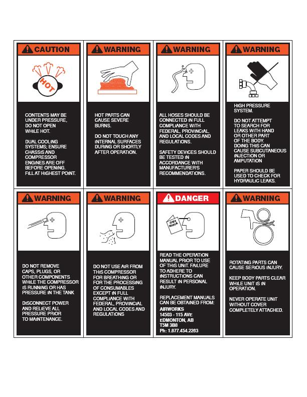
4 Safety Precautions Observe the Following General Safety Rules a) Read and understand operation manual and all related safety materials, before operating machine. Installer to ensure manual and all safety decals are delivered with unit on completion of product installation. b) Follow safe work practices and wear the appropriate safety equipment when operating airpower equipment. c) Avoid contact with the drive system. Do not operate with panels removed. d) Avoid skin contact with pressurized air. Injury or death may result. e) Make sure the air entering the compressor is free of flammable vapours that could cause an explosion. f) Vaporized oil propelled by high pressure air is an explosive mixture. g) Do not breathe the compressor air. Vaporized oil is a respiratory hazard. h) Components are hot during and following operation; use caution. i) Disconnect all power before any servicing. j) Do not attempt to service compressor while under pressure; remove fill cap and filters slowly. k) Never refuel unit while running or hot. l) Avoid sparks and flame when refuelling m) Fuel in a well ventilated area only. n) If using electric generator or welder options ensure all components in good condition, use in dry location only, refer to manual. When operating the compressor: Ensure all users are familiar with safe operation and have read this manual. a) Do not bypass any of the units safety shut down devices. b) Do not expose the unit to extreme heat. c) Do not repair or service a pressurized system. d) Maintenance and repairs are to be performed by qualified personnel only. e) Do not tamper with the pressure relief valve. f) Do not attempt to modify any component. g) Do not operate with cover or doors removed. h) Do not use replacement or service parts other than Airworks recommended components. i) Compressor may start at any time discount power before serving. Safety Features a) 200 psi relief valve b) Temperature safety shut down on engine and compressor c) Rapid blow down valve to discharge system pressure on compressor side of system after unit is shut down d) Low oil pressure shut down on engine e) Outer enclosure prevents contact with hot and moving parts. f) Optional low coolant sensor include in all cold weather kits) g) Warning decal 3
5 Lubrication and Filters a) Use only Airworks certified and approved engine and compressor oils and filters b) Compressor may be under pressure; ensure pressure is released and unit is unloaded before servicing, remove fill cap slowly stop if pressure is present until compressor unloads. c) Oil filters are spin-on type d) Air filters are paper type replaceable e) Spin on coalescing separator element Operating Principals The system uses a flooded lobe, rotary screw compressor. The oil filled compressor contains two rotors turning at a variable speed. When air at atmospheric pressure is introduced into the housing, by the inlet control vavlue it is trapped between the rotors allowing for compression. A lubricated pitch line provides sealing. As the lobes on the rotors mesh, they reduce the volume of air, compressing it to the desired pressure. Oil separation occurs in two stages. One: the mechanical; where the air/oil is first separated through a series of baffles and Two: by the coalescing filter. A liquid to liquid cooling system is used to maintain compressor oil temperature. This system uses the cooling system of the prime mover to act as a heat sink for heat transfer and may also use an air to oil cooler. Rotary screw compressors are machined to close tolerances and ingestion of foreign objects into the system will rapidly damage or shorten the life expectancy of the unit. Important Driving while your unit is running may cause damage to be incurred. Shut your unit off prior to moving your vehicle to prevent this. 4
6 Routine Maintenance You must follow the maintenance schedule and use only Airworks genuine replacement parts to maintain your system and warranty. The most critical aspect of maintenance is proper air filtration and clean oil. If any particles enter the compressor through the air inlet or other means, they can contaminate roller bearings, gears and rotors in the compressor. Contamination will cause severe and rapid damage to components. Ensure compressor is completely unloaded before servicing. Clean Areas to be serviced. Remove fill cap and filters slowly. Damage caused by contamination not covered by warranty. Maintenance Schedule The following maintenance schedule should be observed to assure good performance and long service life. The hours indicated are displayed on the unit s hour meter. To maintain warranty it is recommended to service Twister minimum once per year regardless or hour used. For replacement parts please order the indicated part numbers from an authorized dealer. 250 Hours Change engine oil and oil filter. Change compressor oil, oil filter, and air filter. Inspect unit coupler assembly, check for leaks, loose fasteners, fittings, wire and hoses chaffing as above. T40/T60 - Airworks Service Kit P/N ATS425 T100/T185 - Airworks Service Kit P/N ATS Hours Change engine oil, oil filter, fuel element, fan belt and air cleaner element. Change compressor oil, oil filter, coalescing filter and air filter. Replace fan belt. Replace coupler insert. Set valve lash. T40/T60 - Airworks Service Kit P/N ATS450 T100/T185 - Airworks Service Kit P/N ATS HR Service Kit Instructions NOTE: Fuel filter housing requires bleeding after fuel filter change. a) Turn unit on without starting engine. b) Loosen screw on top of fuel filter housing until a steady flow of fuel is seen. c) Tighten screw, start unit, check for leaks. Clean up any spilt fuel or oil and dispose of properly. Inspect all components for loose or rubbing parts and adjust valve lash. Inspect all items for wear, including drive coupler. Check for fluid and air leaks. Check air pressure and engine speed settings. 5
7 Value Lash Settings Cold Kobota 482 Intake / Exhaust Yanmar 3TNV Intake / Exhaust Twister Starting Procedure Diesel Engines * Turn ignition key to the left and hold for 15 seconds. This primes the fuel pump and engages the pre-heater. In cold temperatures below -10 degrees C), hold pre-heater for up to ONE minute if required NOTE: NEVER USE STARTING FLUIDS * Now turn the key to the right crank position). When engine has started release key. * When engine has reached operating temperature, engage the compressor switch; this will allow the compressor to start. * When pressure reaches preset pressure 150 to 170 psi) unit will idle down. * System is now ready for use. Twister Shutdown Procedure Diesel Engines * Switch compressor button off. * Compressor will disengage and bleed off pressure. * Allow engine to idle 30 seconds * Turn key to off position. * Engine will stop * Never shut the engine off with compressor under load. This may result in compressor damage. 6
8 Coolant Fill Instructions For Use With Cold Weather Kit NEVER OPEN THE COOLING SYSTEM WHILE HOT! Perform a visual check of both the chassis engine and the Twister coolant expansion bottle with both engines cold. The Twister expansion bottle should be 1/3 full or less. Consult the chassis owner s manual for the correct chassis coolant level. Check the coolant level in the Chassis reservoir Coolant should be at the manufacturer s suggested level. If low, open cap very slowly, if coolant remains in Twister, it will spill into chassis reservoir as the air lock is broken. Allow to fill to manufacturer s suggested level from Twister or if required add additional coolant. Once suggested level is reached, close system and DO NOT OPEN AGAIN. Check the coolant level in the Twister SLOWLY open the Twister radiator cap. Correct coolant level is ½ inch above radiator core when cold. If level is not above the core of the radiator, add coolant using the same coolant as suggested by the chassis manufacturer. Do not fill upper radiator tank to top as room is required for expansion as truck and/or Twister heat up. Overfilling will cause coolant overflow at the Twister. Test the system by running the Twister or the chassis engine. Let engines) cool and check for correct level and fill AT THE TWISTER) as necessary until the coolant is at the correct level. TIP: If chassis reservoir has been overfilled by opening the cap and breaking the air lock or by simply adding too much coolant while performing the above checks, ensure that the Twister coolant level is LOW. The coolant levels will then balance themselves as the Twister/truck runs. After running, allow to cool down and recheck levels at both the chassis and Twister. Coolant level should be correct in chassis reservoir. If low at the Twister, add coolant to the Twister to bring to correct level ½ inch above core. 7
9 Pressure Regulation and Engine Speed Control The system uses two control systems. One, an air pressure switch and the other, an engine speed control. This allows for instant response to air demands based on air flow and reduction of load on the engine and reduces fuel usage. These items are set at the factory and should not require adjustment. Adjusting the System If insufficient airflow is developed under high demand conditions, check the engine RPM. The throttle control is preset for maximum delivery by the system at all airflow demands within the unit s abilities at the factory, but in some instance may require minute adjustment by the user. This is done by adjusting the linkage on the throttle control to increase or decrease the engine RPM. The cut out and cut in pressure of the compressor can be adjusted on the pressure switch. Consult your Airworks dealer before attempting adjustment. Airflow and system pressure are related. As the cfm requirements increase, the pressure produced during flow, as with any air system, diminishes. The Twister is designed to efficiently run tools requiring air at 90 psi tool manufacturer s standard psi rating). If you must set up a system without knowing the demands on the system, you can make adjustments by using an orifice in the outlet to stimulate tool use. A system testing and adjustment tool is available from Airworks ATT001). 8
10 Trouble Shooting the System Quick accurate diagnosis of problems will help to effect repairs in a timely fashion and should involve the following: a) Understand the operational characteristics of the system to better determine the problem. b) Run the system, if possible, to determine the problem. c) Do not perform test procedures that are harmful to people or equipment. d) Perform repairs using the correct parts and procedures. e) Consult your local dealer or Airworks Compressors Corp. Symptom: Compressor does not produce adequate air Check and correct the following: a) Compressor oil level is correct b) Coupling between engine and compressor is intact c) Pressure switch is operational d) Air filters are clean e) Engine RPM is set to spec, adjust as required f) Blockage downstream of compressor Symptom: Frequent over-temperature shut downs Check and correct the following: a) Check engine and compressor oil levels b) Check engine coolant level, while unit is cool c) Check engine and compressor hoses for kinks d) Check engine and compressor over temp shut down temp probes e) Check for adequate air circulation around unit, hot air shall not be drawn into unit. f) Check oil filters not plugged g) Fan belt is properly adjusted 9
11 Symptom: Excessive air pressure Check and correct the following: a) Check pressure switch for correct operation b) System pressure line leakingfrom compression to pressure switch) c) Inlet valve functioning and no oil in compressor air filter Symptom: Engine stalls when compressor starts Check and correct the following: a) Engine fuel filter or air filter plugged - replace b) Fuel pump functioning c) Air compressor is under pressure allow to unload d) Operating speed is too low adjust as required e) Blow down valve operating properly f) Compressor switched on, building pressure should be off to start) g) Positive air shut off tripping optional not on all units) Symptom: Low air pressure Check and correct the following: a) Air flow capacity exceeded reduce load demand on compressor b) Engine speed too low adjust as required c) Pressure regulator/switch not operating properly adjust or replace as required Symptom: Excessive oil in the air produced Check and correct the following: a) Check compressor oil level ensure correct level b) Check oil scavenging line is clear clear and inspect c) Check coalescing filter replace as required 10
12 Symptom: Oil blows out of compressor air filter on shut down Check and correct the following: a) Unit shut down while compressor under load b) check inlet control valve seal repair as require Symptom: Diesel engine turns but will not start Check and correct the following Symptoms: a) Adequate fuel supply b) Glow plugs - test c) Compressor switch on/turn off d) Fuel filter restricted/valve off bleed air from filter housing e) Positive air shut off tripped optional not on all units) f) Fuel pump operation check flow Engine Smoking Lack of Power Check and correct the following a) Check coolant level b) Air in fuel filter c) Operating in hot environment air intake can be routed to outside fresh air) 11
13 Caring for Your Twister Your Twister is designed to provide many thousands of hours of working life. By following the listed procedures you will ensure this happens and protect your investment and warranty. Every 25 hours Check fluid levels Check for loose or rubbing components, leaks, air and fluid Every 100 hours As above plus Check air filter elements condition Check fan belt tension Check fuel filter Every 250 hours As above plus Service engine and compressor oil and filters Check radiator hoses and clamps Check air intake hose Check hoses for rubbing and/or wear Check replace belts as required Every 500 hours As above plus Service engine oil and filters Check radiator hoses and clamps Check air intake lines Replace coupler on engine and compressor Replace the fuel filter element Clean the radiator external fins Replace the fan belt/replace generator belt if required Check valve lash see page 5) 500 HR Service Kit Instructions NOTE: Fuel filter housing requires bleeding after fuel filter change. a) Turn unit on without starting engine, to run fuel pump b) Loosen screw on top of fuel filter housing until a steady flow of fuel is seen. c) Tighten screw, start unit, check for leaks. Clean up any spilt fuel and dispose of properly Every 2 years Replace radiator hoses and clamps Change radiator coolant Replace air intake hose 12
14 Warranty Policy General Provisions and Limitations 1. Airworks Compressor Corp. warrants to each original retail purchaser here after the buyer) of its new air compressor system from Airworks or its authorized dealers that such products are free from manufacturer s defects in material and workmanship. 2. No warranty is made with respect to: a) Any products which in Airworks judgment have been subject to negligence, accident or improper storage, installation, application, operation or maintenance, or have been altered or repaired in such a way that effects the product adversely. b) Operation of unit with low coolant level will cause damage no covered by warranty. c) Components or accessories manufactured, warranted and serviced by other than authorized dealer. d) Consequential damages) caused by Products failure. e) Any products) if other than Airworks genuine components are used in the Product and/or installation f) Normal wear and tear g) Paint and cosmetic items 3. The warranty period will commence upon installation of the product. The returned warranty registration form marks the date of installation. If the warranty registration form has not been received by Airworks within 2 months from the date of purchase then the warranty period will be deemed to commence 30 days from date of shipment from Airworks. 4. a) T40/T60 Air end has a limited life time warranty inquire) b) The units are warranted for two 2) years or two thousand 2000) hours, whichever occurs first, against manufactures defects in materials and workmanship. 5. Replacement parts, electrical components and cosmetic items at Airworks discretion) shall be warranted for a period of six 6) months or three hundred 300) hours, whichever occurs first. 6. Airworks Obligation a) Airworks obligation is limited to repairing or at Airworks option, replacing; during normal business hours at an authorized service facility of Airworks, any component, which in Airworks judgment is proven to be defective as warranted. b) Airworks obligation is limited to Products) proven to be warranted. No liability is accepted for any consequential damages, injuries or expenses directly or indirectly related to the Products failure. c) Airworks is not responsible for any costs incurred due to lost time or travel related to warranty issues. d) Airworks is not responsible for time required to service or repair product due to mounting location. e) Airworks is not responsible for return shipping to Airworks of failed components. f) Airworks will be responsible for ground shipment or replacement of validated warranty parts. g) Airworks is to be contacted prior to any possible warranty repairs are undertaken for warranty consideration. 13
15 Buyers Obligations a) You, the buyer, are obligated to notify your dealer within 10 days of any defect and return defective part within 30 days of notification. b) The buyer must prepay all the costs associated with the warranty claim and submit receipts/invoices to your dealer for evaluation. c) The buyer must return components returned under this agreement to your dealer, designated by Airworks, for evaluation, to establish a claim under this warranty. d) Buyer shall maintain and service Airworks products in accordance with this manual. Warranty Registration Validations * A warranty registration is supplied to the buyer with the product that must be returned to Airworks at time of installation. Disclaimer and Warranty Service a) Any labour costs incurred in excess of Airworks set labour rates are not covered. b) Any travel time or labour costs incurred by unauthorized personnel are not covered by this warranty. c) Any related service/repair costs incurred due to mounting location and accessibility are not covered by this warranty. d) This warranty is in lieu of all other warranties expressed or implied e) All warranty claims must be pre-authorised by Airworks and components returned prepaid using the assigned RGA number. 14
16
17
18
19
20
21
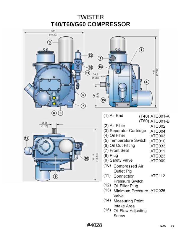
22 TWI STER T40/ T60ENGI NE 1)Wat erdr ai ncock ATE049 2)I nt akemani f ol d ATE052 3)FuelPump ATE013 4)Oi llevelgauge ATE054 5)SpeedCont r ollever ATE046 6)I nj ect i onpump ATE057 7)Engi nest oplever ATE047 8)Cool i ngfan ATE038 9)FanDr i vepul l ey ATE048 Copy r i ghtai r wor k scompr es s or scor p. 10)Oi ldr ai nfi t t i ng ATE )St ar t er ATB002 12)Oi lfi l t ercar t r i dge ATE028 13)Oi lpr essur eswi t chatb005 14)Al t er nat or40amp ATB028 15)Oi lfi l l ercap ATE050 16)ExhaustMani f ol d ATE051 17)Fl ywheel ATE009 # / 14

23 Dimensionsinmm inch) CopyrightAirworksCompressorsCorp.
24
SPECIALTY AIR COMPRESSOR SYSTEM OWNER'S MANUAL
 VEHICLE MOUNTED AIR COMPRESSORS COMPACT. POWERFUL: M SPECIALTY AIR COMPRESSOR SYSTEM OWNER'S MANUAL System# www.vmacair.com VMAC Specialty Products Owner s Manual Introduction... 3 Ordering Parts... 3
Open Frame Gas/Diesel Engine Driven Rotary Screw Compressor. Installation Guide
 Open Frame Gas/Diesel Engine Driven Rotary Screw Compressor Installation Guide Air compressors should only be installed trained installation personnel call 800-531-9656 to find a local trained. Warning:
TP300 INDUSTRIAL TRASH PUMP OPERATOR S MANUAL
 TP300 INDUSTRIAL TRASH PUMP OPERATOR S MANUAL IT IS EXTREMELY IMPORTANT TO READ AND UNDERSTAND THE ENTIRE CONTENTS OF THIS OPERATOR S MANUAL BEFORE ATTEMPTING TO OPERATE THE PRODUCT. THIS EQUIPMENT IS
DIRECT-DRIVE PRESSURE WASHERS
 DIRECT-DRIVE PRESSURE WASHERS PJG SERIES PRESSURE WASHER MANUFACTURED BY: PJG-2002B PJG-2502-6.5B PJG-3002B PJG-4002B INTRODUCTION Thank you for purchasing a Mancorp Pressure Washer. This manual covers
SECTION 3.00 WARNING WARNING ENGINE STARTUP AND SHUTDOWN PRESTART INSPECTION
 SECTION 3.00 ENGINE STARTUP AND SHUTDOWN PRESTART INSPECTION Be sure that the clutch, circuit breaker, or other main power transmission device is disconnected. Generators develop voltage as soon as the
SPECIFICATIONS Horsepower: 1.5 HP Running Maximum PSI: 125 PSI Tank Capacity: 15 Gallons CFM: 6 40 PSI 5 90 PSI
 15 GALLON AIR COMPRESSOR Model: 7678 DO NOT RETURN TO STORE Please call 800-348-5004 for parts and service CALIFORNIA PROPOSITION 65 WARNING: You can create dust when you cut, sand, drill or grind materials
Installation Manual for P170002/R Compressor Lincoln Air Vantage 500 Welder (Cummins)
") Installation Manual for P170002/R170003 Compressor Lincoln Air Vantage 500 Welder (Cummins) 1.0 Information... 4 2.0 Preparation... 14 3.0 Compressor Removal... 14 4.0 Flushing Procedure... 15 5.0 Compressor
Installation Manual for P170002/R170003 Compressor Lincoln Air Vantage 500 Welder (Cummins) 1.0 Information... 4 2.0 Preparation... 14 3.0 Compressor Removal... 14 4.0 Flushing Procedure... 15 5.0 Compressor
Gas Engine Driven 30 CFM Air Compressor Installation, Owner s and Service Manual G300003
 Gas Engine Driven 30 CFM Air Compressor Installation, Owner s and Service Manual G300003 Gas Engine Driven 30 CFM Air Compressor Installation, Owner s and Service Manual G300003 Safety...3 Warranty...4
WEBER CARBURETOR TROUBLESHOOTING GUIDE
 This guide is to help pinpoint problems by diagnosing engine symptoms associated with specific vehicle operating conditions. The chart will guide you step by step to help correct these problems. For successful
1500 Series Roll Off Hoist. Owner s Manual (5-06)
") 1500 Series Roll Off Hoist Owner s Manual (5-06) Section 1: General Information Introduction Safety Information Warranty Information Table of Contents Section 2: Operation Operating the P.T.O. Operating
1500 Series Roll Off Hoist Owner s Manual (5-06) Section 1: General Information Introduction Safety Information Warranty Information Table of Contents Section 2: Operation Operating the P.T.O. Operating
Warranty. (Product Disclosure Statement, PDS) 36 months or 2,000 service hours For Shindaiwa manufactured Mobile Generators and Welders
 36 months or 2,000 service hours For Shindaiwa manufactured Mobile Generators and Welders") Warranty (Product Disclosure Statement, PDS) 36 months or 2,000 service hours For Shindaiwa manufactured Mobile Generators and Welders Please see Engine manufacturers warranty in section 3.1 of this document*
Warranty (Product Disclosure Statement, PDS) 36 months or 2,000 service hours For Shindaiwa manufactured Mobile Generators and Welders Please see Engine manufacturers warranty in section 3.1 of this document*
CAUTION. Start & Stop Procedures. Section 1-2. Engine Oil Level
 Section 1-2 Start & Stop Procedures Before operating this machine, the operator must have: received operator training, a familiarity with this manual, and a complete understanding of all the procedures
INSTALLATION AND OPERATING
 Publication T5-704, Rev. 4 Dated: November 1, 2006 INSTALLATION AND OPERATING MANUAL T50-P TURBOTWIN Engine Air Starter AN 99-448 TABLE OF CONTENTS Section Subject Page 1.0 General Information. 1 2.0 Orientation
AIR COMPRESSOR OPERATING INSTRUCTION AND PARTS LIST
 AIR COMPRESSOR OPERATING INSTRUCTION AND PARTS LIST BELT TYPE IMPORTANT PLEASE MAKE CERTAIN THAT THE PERSON WHO IS TO USE THIS EQUIPMENT CAREFULLY READS AND UNDERSTANDS THESE INSTRUCTIONS BEFORE STARTING
RED23305 Owner s Manual
 RED23305 Owner s Manual 5 foot, 3-Point Mounted Snow Blower 270 West Park Avenue Huron, SD 57350 866-526-5682 Serial Number: Date of Purchase: Red Devil Snow Blower See Figure 1. 1. The Red Devil Snow
11202 INSTALLATION INSTRUCTIONS
 11202 INSTALLATION INSTRUCTIONS WARNING! The fuel system may be under pressure. Do not open the fuel system until any pressure has been relieved. The enclosed Aeromotive fuel pump utilizes an o-ring sealed
RAPTAIR-G30 Gas Drive Air Compressor Installation, Owner s and Service Manual G300002
 RAPTAIR-G30 Gas Drive Air Compressor Installation, Owner s and Service Manual G300002 RAPTAIR-G30 Gas Drive Air Compressor Installation, Owners and Service Manual G300002 General Information... 3 Safety
Pump Sentry. Models 812 PS & 1612 PS INSTALLATION INSTRUCTIONS
 Pump Sentry Models 812 PS & 1612 PS INSTALLATION INSTRUCTIONS The Pump Sentry is an innovative power station designed to operate your pump during a power outage. When properly installed, it will provide
General Information - Inspection, Delivery, Service and Warranty Forms. Delivery and Inspection Information
 Section 1.1 General Information - Inspection, Delivery, Service and Warranty Forms Delivery and Inspection Information... 1.3.2 Pre-Delivery Inspection Form... 1.3.3 Delivery Report... 1.3.5 100-200 Hr
INSTALLATION AND OPERATING MANUAL
 Dated: May 10, 2001 INSTALLATION AND OPERATING MANUAL MODEL: T30-Y TURBOTWIN Engine Air Starter From Tech Development Inc AN96-425 6800 Poe Ave. Dayton OH 45414 Tel: (937) 898-9600 Fax: (937) 898-8431
If there is additional labor or other costs above the 4 hrs labor you must call VMAC for approved coverage
 Installation Manual for the A500027 RAPTAIR MF Dual Air Filter Retrofit Kit Author: Brian Collings Date: 15/07/2014 1900997 - Manual, Installation (A500027) Systems or Parts Affected: D600005BETA01-D600005BETA59
TRANSPORT HYDRAULIC COOLING SYSTEM
 Resource Manual Installation Guide Operating Procedures Parts Breakdown MODEL SS600 TRANSPORT HYDRAULIC COOLING SYSTEM MODELS SS600ER Electric Fan with Relief Valve SS600EV Electric Fan with Control Valve
11101, & INSTALLATION INSTRUCTIONS
 11101, 11108 & 11151 INSTALLATION INSTRUCTIONS WARNING! The fuel system is under pressure. Do not open the fuel system until the pressure has been relieved. Refer to the appropriate vehicle service manual
H.S. MACHINERY RING COMPRESSORS
 OPERATION & PARTS MANUAL Thank you for purchasing an H.S Machinery Limited Regenerative Blower. This product is manufactured under strict ISO-9001-2000 quality control guidelines to ensure your satisfaction.
OBE, OBEXU, ON BOARD Battery Chargers
 C O R P O R A T IO N O P E R A T I N G I N S T R U C T I O N S OBE, OBEXU, ON BOARD Battery Chargers INTRODUCTION: These chargers are designed for the permanent installation on battery powered vehicles
MOBILE HYDRAULIC COOLING SYSTEMS MODELS AVAILABLE IN BOTH VERSIONS
 Resource Manual Installation Guide Operating Procedures Parts Breakdown MODEL 934 MOBILE HYDRAULIC COOLING SYSTEMS MODELS AVAILABLE IN BOTH VERSIONS SS/BK934ER Electric Fan with Relief Valve SS/BK934EV
SHOP PRO FXP 95 TECHNICAL MANUAL
 SHOP PRO FXP 95 TABLE OF CONTENTS Applications and Features... 1 Shop Pro FXP 95 Components... 2 Important Safety Precautions.... 3 Set-up and Maintenance... 4 Prevent Fuel Spillage... 5 Hoses and Adapters...
Portable Electric/Gas Compressor Operating Instructions
 Portable Electric/Gas Compressor Operating Instructions NOTICE Carefully read this instruction manual before attempting to operate this compressor. MODEL # SERIAL # 1-800-551-2406 TABLE OF CONTENTS Safety
INSTALLATION, OPERATION, AND MAINTENANCE INSTRUCTIONS. Part Number: P DM
 INSTALLATION, OPERATION, AND MAINTENANCE INSTRUCTIONS Whole House Duct-Mount HEPA Air Cleaner Part Number: P102-400DM TABLE OF CONTENTS Page SAFETY CONSIDERATIONS...1 INTRODUCTION...1,2 INSTALLATION...2,3
OBAE, OBAEXU, ON BOARD Battery Chargers
 C O R P O R A T IO N O P E R A T I N G I N S T R U C T I O N S OBAE, OBAEXU, ON BOARD Battery Chargers INTRODUCTION: The OBAE line of chargers are designed for the permanent installation on battery powered
AIR/HYDRAULIC INJECTION GUN MODEL INSTRUCTIONS
 I. OPERATION & DESCRIPTION The Air / Hydraulic Injection Gun is a high-pressure tool that should be used with caution and according to these instructions. IMPORTANT: The Gun is 0,000 psi rated. Do not
KING CANADA 950W PORTABLE GENERATOR MODEL: KCG-951G INSTRUCTION MANUAL COPYRIGHT 2011 ALL RIGHTS RESERVED BY KING CANADA TOOLS INC.
 KING CANADA 950W PORTABLE GENERATOR MODEL: KCG-951G INSTRUCTION MANUAL COPYRIGHT 2011 ALL RIGHTS RESERVED BY KING CANADA TOOLS INC. WARRANTY & SERVICE INFORMATION 1-YEAR LIMITED WARRANTY FOR THIS 950W
INSTALLATION AND OPERATING MANUAL
 Publication T3-76, Rev. 1 Dated: May 9, 21 INSTALLATION AND OPERATING MANUAL MODEL: T3-I TURBOTWIN Engine Air Starter AN96-419 From Tech Development Inc 68 Poe Ave. Dayton OH 45414 Tel: (937) 898-96 Fax:
13101 / / and Installation Instructions
 13101 / 13151-13109 / 13159 and 13114 Installation Instructions WARNING! The fuel system is under pressure. Do not open the fuel system until the pressure has been relieved. Refer to the appropriate vehicle
6 Litre Oil-Less Air Compressor
 Operator s Manual 6 Litre Oil-Less Air Compressor WARNING! Before using this appliance, read the Operator s manual and follow all its safety rules and instructions. SPECIFICATION HWKAC1 1.1 kw / 1.5 HP
VR LITE AIR COMPRESSOR OWNERS MANUAL
 VR LITE AIR COMPRESSOR OWNERS MANUAL General Information... 4 Introduction... 4 Ordering Parts... 4 Safety Messages... 4 Important Safety Notice... 5 Safety Precautions... 7 Personal Hazards... 8 System
8" - 12" Hydraulic Steel Squeeze Off Tool
 8" - 12" Hydraulic Steel Squeeze Off Tool ECN 19130 C812S Hydraulic Steel Squeeze Off Tool for Steel Pipe Page 1 of 8 This Footage Tools C812S Steel Squeeze Off Tool is sold with one pump configuration
Operating Instructions - Electric Pow'r-Riser Models
 ADivisionOf Templeton, Kenly& Co., Inc. Operating Instructions - Electric Pow'r-Riser Models Table of Contents 1.0 Recieving Instructions 2.0 Safety 3.0 Specifications 4.0 Initial Installation Before Operating
MODEL SS675 TRANSPORT HYDRAULIC COOLING SYSTEM
 Resource Manual Installation Guide Operating Procedures Parts Breakdown MODEL SS675 TRANSPORT HYDRAULIC COOLING SYSTEM MODELS SS675ER / SS675ER-ND SS675HR / SS675HR-ND SS675E000ND / SS675H000ND SS675ND-COMBO
Enclosed Electric Rotary Screw Compressor Installation Guide
 Enclosed Electric Rotary Screw Compressor Installation Guide Air compressors should only be installed trained installation personnel call 800-531-9656 to find a local trained. Warning: Read all installation
Owner s Manual Supplement. Liquefied Petroleum Gas (LPG) Fuel System for 1998 GM Medium Duty Chassis (C-60/C-70) with 6.0L and 7.
 Fuel System for 1998 GM Medium Duty Chassis (C-60/C-70) with 6.0L and 7.") Owner s Manual Supplement Liquefied Petroleum Gas (LPG) Fuel System for 1998 GM Medium Duty Chassis (C-60/C-70) with 6.0L and 7.0L V8 OWNERS MANUAL SUPPLEMENT Table of Contents Refueling Your Vehicle...1
Owner s Manual Supplement Liquefied Petroleum Gas (LPG) Fuel System for 1998 GM Medium Duty Chassis (C-60/C-70) with 6.0L and 7.0L V8 OWNERS MANUAL SUPPLEMENT Table of Contents Refueling Your Vehicle...1
before serial number 2214
 before serial number 2214 Contents Page Safety Rules... 3 Pre-operational & Safety Inspection... 4 Operating Instructions... 6 Transport... 12 Maintenance & Routine Service... 12 Specifications... 14 SAFETY
A.W.E. Tuning Turbo Warranty Registration Certificate
 A.W.E. Tuning Turbo Warranty Registration Certificate Dear Customer, Thank you for your purchase. Please take a few minutes to familiarize yourself with the conditions of our warranty as outlined on the
BATTERY & STARTER ANALYSER (BSA-12) User Manual
 User Manual") BATTERY & STARTER ANALYSER (BSA-12) User Manual Introduction BSA-12 Battery Starter Analyser does not carry internal batteries but is powered up from external DC source ranging from 9V to 15V DC. It is
BATTERY & STARTER ANALYSER (BSA-12) User Manual Introduction BSA-12 Battery Starter Analyser does not carry internal batteries but is powered up from external DC source ranging from 9V to 15V DC. It is
General Installation Instructions for Valves and Gates
 General Installation Instructions for Valves and Gates Thank you for your purchase of a Lorenz valve. We appreciate your business! Please read this installation manual and follow recommended safety precautions.
AEROMOTIVE Part # /2 4.6L SOHC Ford Fuel Rail Kit INSTALLATION INSTRUCTIONS
 AEROMOTIVE Part # 14125 96-98 1/2 4.6L SOHC Ford Fuel Rail Kit INSTALLATION INSTRUCTIONS CAUTION: Installation of this product requires detailed knowledge of automotive systems and repair procedures. We
Active Controlled Cooling System
 Active Controlled Cooling System April 2011 3267 Progress Dr Orlando, FL 32826 www.apecor.com Preliminary www.apecor.com Table of Contents General Information... 3 Safety... 3 Introduction... 3 What s
PRODUCT NUMBERING SYSTEM SERIES PHASE. 1: Single Phase 3: Three Phase
 TABLE OF CONTENTS Product Numbering System and Specifications... Safety... Receiving and Inspection... Installation... Electrical...6 Start-up...7 INTRODUCTION The compressor you have purchased is a combination
CAUTION. Start & Stop Procedures. Section 4-2. Engine Oil Level
 Section 4-2 Start & Stop Procedures Before operating this machine, the operator must have: received operator training, a familiarity with this manual, and a complete understanding of all the procedures
Users Manual Certified Series Direct Drive Pump 1-7 LPM
 Users Manual Certified Series Direct Drive Pump 1-7 LPM Safety, Operating, Installation, and Maintenance Instructions 600 S 56 th Street #9 Chandler, AZ 85226 Phone: 480-507-6478 Fax: 480-838-2232 www.fogco.com
Hazardous Location Direct-Drive Exhaust Fans. Operating Instructions & Parts Manual
 Operating Instructions & Parts Manual EN Hazardous Location Direct-Drive Exhaust Fans Models 10D996 thru 10D999, 10E001 thru 10E007, 10E009 thru 10E020, 32ZN53 and 32ZN54 474904 PLEASE READ AND SAVE THESE
11104 & Installation Instructions
 11104 & 11110 Installation Instructions WARNING! The fuel system is under pressure. Do not open the fuel system until the pressure has been relieved. Refer to the appropriate vehicle service manual for
6L Oil-less Air Compressor 53103
 6L Oil-less Air Compressor 53103 Operating Instructions Please read and save these instructions before attempting to assemble, install, operate or maintain the product. Protect yourself and others by observing
Operating instructions Form no safety definitions
 Operating instructions Form no. 1000437 safety definitions safety symbols are used to identify any action or lack of action that can cause personal injury. Your reading and understanding of these safety
HALLMARK INDUSTRIES INC
 Performance Part No. HP. CONVERTIBLE JET PUMP USER S MANUAL GPH of Water @ Total Discharge Pressure of 40 psi Max. Pressure Max suction (shallow well) Max Suction (deep well) Max GPM (@0 head) Max Discharge
TC Series Cooling Systems
 TC Series Cooling Systems Table of Contents Table of Contents...1 List of Figures...1 Safety...2 Introduction...2 General Specifications...2 Types of Coolant...2 Routine Maintenance...2 Surge Tank Coolant
MODEL A97 SERIES. Switchmode Utility Rectifier/Battery Charger ECN/DATE
 MODEL A97 SERIES Switchmode Utility Rectifier/Battery Charger CPN108172 ISSUE DATE: 16071 7/03 ECN/DATE 106 BRADROCK DRIVE DES PLAINES, IL. 60018-1967 (847) 299-1188 FAX: (847)299-3061 Page 1 of 7 INSTRUCTION
Owner s/operator s Manual
 Water Pump MP2533E2 Owner s/operator s Manual Completely read and understand this manual before using this product. Foreword This Owner s/ Operator s Manual is designed to familiarize the operator with
PEDESTAL SUMP PUMP. MODEL # Español p. 11. Zoeller is a registered trademark of Zoeller Co. All Rights Reserved.
 PEDESTAL SUMP PUMP Zoeller is a registered trademark of Zoeller Co. All Rights Reserved. MODEL #1084-0001 Español p. 11 ATTACH YOUR RECEIPT HERE Serial Number Purchase Date Questions, problems, missing
QPET, QPETXU Battery Chargers
 C O R P O R A T IO N O P E R A T I N G I N S T R U C T I O N S QPET, QPETXU Battery Chargers INTRODUCTION: The QPET line of chargers are designed for general purpose deep cycle batteries. They are an electronically
ACF Operation Manual
 ACF-3000 Operation Manual MAHLE Aftermarket Inc., RTI Division 10 Innovation Drive York, Pennsylvania 17402 USA Phone: 717-840-0678 Toll Free: 800-468-2321 Web-site: www.rtitech.com Manual P/N: 035 81825
Installation, Operation & Maintenance Manual
 Installation, Operation & Maintenance Manual Picture may differ from your specific application For Pro-Fill kits with part numbers beginning in BG BL-175 9-20-13 General Information & Precautions This
SUBMERSIBLE SUMP PUMPS
 SUBMERSIBLE SUMP PUMPS Zoeller is a registered trademark of Zoeller Co. All Rights Reserved. MODELS #1073-0001, 1075-0001 Español p. 9 ATTACH YOUR RECEIPT HERE Serial Number Purchase Date Questions, problems,
Racor 75500FGX Turbine Series fuel
 Installation Instructions 75500FGX Fuel Filter Racor 75500FGX Turbine Series fuel filter/water separator assemblies are designed to be installed on the vacuum side of the fuel transfer pump for best efficiency
Hydraulic Immediate Need Power Pack
 Safety, Operation, and Maintenance Manual WARNING Improper use of this tool can result in serious bodily injury This manual contains important information about product function and safety. Please read
OWNER/OPERATOR MANUAL. Airmotor effective dia. in. 2.5
 MODELS 282050, 282716 & 283513 AIR OPERATED CHASSIS PUMP SERIES A OWNER/OPERATOR MANUAL SPECIFICATIONS Airmotor effective dia. in. 2.5 Airinlet Material outlet 1/4 NPTF 1/4 NPTF Liquid to Air Pressure
AEROMOTIVE Part # Street Rod Fuel Pump System INSTALLATION INSTRUCTIONS
 AEROMOTIVE Part # 17201 Street Rod Fuel Pump System INSTALLATION INSTRUCTIONS CAUTION: Installation of this product requires detailed knowledge of automotive systems and repair procedures. We recommend
GARDEN HOSE UTILITY PUMP
 GARDEN HOSE UTILITY PUMP MODEL #HPP360, HPP12V, 473707 MODEL #HPP360, 473707 MODEL #HPP12V ATTACH YOUR RECEIPT HERE Purchase Date SAFETY INFORMATION Please read and understand this entire manual before
CLEAN POWER TM CPS Series Operator s Manual
 12 Test Equipment CLEAN POWER TM CPS Series Operator s Manual Power Supply / Maintenance Charger for 12 Volt Systems The CPS series of power supplies / maintenance chargers are the ultimate in supplying
QSSE, QSSEX INDUSTRIAL Battery Chargers
 C O R P O R A T IO N O P E R A T I N G I N S T R U C T I O N S QSSE, QSSEX INDUSTRIAL Battery Chargers INTRODUCTION The QSE line are electronically controlled float chargers. The batteries are brought
SHOP PRO FXP TECHNICAL MANUAL. FOR ADDITIONAL INFORMATION, VISIT TABLE OF CONTENTS
 SHOP PRO FXP TABLE OF CONTENTS Applications and Features...1 Shop Pro FXP Components...2 EEImportant Safety Precautions.... 3 Set-up and Maintenance...4 Hoses and Adapters....5 Hose Connections for Priming...6
CONTENTS. VMAC Vehicle Mounted Air Compressors Toll Free: Local: Fax:
 CONTENTS 1.0 Information... 4 1.1 Foreword... 4 1.2 Important Safety Notice... 4 1.3 Safety Messages... 5 1.4 System... 8 1.5 Auxiliary Air Tank... 9 2.0 Routine Maintenance... 11 2.1 Maintenance Schedule...
INSTALLATION GUIDE. Universal System for Zero Turn Mowers
 INSTALLATION GUIDE Universal System for Zero Turn Mowers Table of Contents General Information 1 Important Notice to Purchaser 2 Specifications 2 Intended Usage 2 Important Information 3 General Safety
PE 20 SERIES ELECTRIC POWER PUMPS
 A Division Of Templeton, Kenly & Co., Inc. PE 20 SERIES ELECTRIC POWER PUMPS Operating Instructions Manual For 1/2 hp, 115 Volt and 230 Volt PEM, PPM, PES and PPS Models Revison B 07/2006 2525 Gardner
Fueltec Models 950AW & 955SS Mobile Fuel Tank Cleaning Systems
 Fueltec Models 950AW & 955SS Mobile Fuel Tank Cleaning Systems Operation Manual Fueltec Systems LLC 828-212-1141 www.fueltecsystems.com FEATURES Stainless steel filter housings to resist the acids found
AEROMOTIVE Part # A2000 Fuel Pump Kit INSTALLATION INSTRUCTIONS
 AEROMOTIVE Part # 17202 A2000 Fuel Pump Kit INSTALLATION INSTRUCTIONS CAUTION: Installation of this product requires detailed knowledge of automotive systems and repair procedures. We recommend that this
OWNER S MANUAL MODEL TTP-300 3X3 Commercial Trash Pump
 OWNER S MANUAL MODEL TTP-300 3X3 Commercial Trash Pump P. O.Box 791, Travelers Rest, S.C. 29690 Phone 864-834-7212 Service/Replacement Parts 800-845-4141 WWW.TITANINDUSTRIAL.NET WARNING! Do Not Operate
M-3025CB-AV Fuel Pump
 SAVE THESE INSTRUCTIONS M-3025CB-AV Fuel Pump Owner s Manual TABLE OF CONTENTS General Information... 2 Safety Instructions... 2 Installation... 3 Operation... 4 Maintenance... 4 Repair... 5 Troubleshooting...
MODEL A96 SERIES. 130Vdc Switchmode Utility Rectifier / Battery Charger. Used with LaMarche Power Cage ECN/DATE
 MODEL A96 SERIES 130Vdc Switchmode Utility Rectifier / Battery Charger Used with LaMarche Power Cage CPN112138 ECN/DATE ISSUE DATE: ECN 17010-12/05 106 BRADROCK DRIVE DES PLAINES, IL. 60018-1967 (847)
ProFlo FatBoy
 The Standard For Professional Grade Diaphragm Pumps. ProFlo 3300 5500 FatBoy Operational and Installation Guidelines, Repair & Parts Contents 3300 5500 Fatboy Operational and Installation Guidelines...2
7.3L POWERSTROKE BANJO BOLT KIT Fits L Powerstroke Diesel. Installation Guide
 7.3L POWERSTROKE BANJO BOLT KIT Fits 94-03 7.3L Powerstroke Diesel Installation Guide INSPECT CONTENTS OF THIS KIT THOROUGHLY BEFORE STARTING THE INSTALLATION PROCESS! IF YOU FIND A PROBLEM WITH YOUR PACKAGE:
S&S. Cycle, Inc. Installation Instructions: Cam Support Plate for 2017-up M8 Models. Instruction
 Instruction 0-0 0-0- Version 0 by S&S Cycle, Inc. All rights reserved. Printed in the U.S.A. S&S Cycle, Inc. 0 Cty Hwy G Viola, Wisconsin Phone: 0-- Fax: 0-- Technical Service Phone: 0--TECH () Technical
AEROMOTIVE Part # Generic Fuel System Kit INSTALLATION INSTRUCTIONS
 AEROMOTIVE Part # 17125 Generic Fuel System Kit INSTALLATION INSTRUCTIONS CAUTION: Installation of this product requires detailed knowledge of automotive systems and repair procedures. We recommend that
Owner s Manual GLASSLINED PUMP TANK
 Owner s Manual GLASSLINED PUMP TANK ANSI/NSF 61 Annex G Thank You for purchasing a pump tank. Properly installed and maintained, it should give you years of trouble free service. If you should decide that
Operator s Manual. Nitro 1000 Nitro 1000X. Nitro 750 Nitro 750X. September REV0
 Operator s Manual Nitro 750 Nitro 750X Nitro 1000 Nitro 1000X September.27.2018REV0 Table of Contents Introduction...3 Safety.....4 Equipment Requirements......5 What You Have Received. 5 Serial Number...6
Hydraulics Troubleshooting
 Hydraulics Troubleshooting Hydraulic Power Units When there is a problem with a KTI Power Unit; from the pump tag we need the Model, Serial Number, Date and the last 6 digits of the trailer VIN#. An option
Routine Compressor Maintenance
 Establishing a regular, well-organized maintenance program and strictly following it is critical to maintaining the performance of a compressed air system. One person should be given the responsibility
AEROMOTIVE Part # and F-Body Fuel System Kit INSTALLATION INSTRUCTIONS
 AEROMOTIVE Part # 17101 and 17102 93-97 F-Body Fuel System Kit INSTALLATION INSTRUCTIONS CAUTION: Installation of this product requires detailed knowledge of automotive systems and repair procedures. We
Portable Oil Free Silent Series Compressor Operating Instructions
 Portable Oil Free Silent Series Compressor Operating Instructions NOTICE Carefully read this instruction manual before attempting to operate this compressor. MODEL # SERIAL # 1-800-551-2406 www.eaglecompressor.com
Installation, Operating and Maintenance Manual
 . Installation, Operating and Maintenance Manual TK 240 Tank Cleaning and Fuel Restoration System www.dieselfueltech.com Email: vernon@dieselfueltech.com Phone: +61 (0) 419 795 676 1 www.dieselfueltech.com
MODEL EGA220 OWNERS MANUAL
 1/4 MINI RATCHET MODEL EGA220 OWNERS MANUAL www.eaglecompressor.com 1-800-551-2406 READ THE ENTIRE MANUAL BEFORE PUTTING THIS TOOL IN SERVICE Limited Air Tool Warranty Wood Industries, Inc. warrants air
24 VOLT AUTOMATIC BATTERY CHARGER PART NO
 24 VOLT AUTOMATIC BATTERY CHARGER PART NO. 957732 AC Input: DC Output: Battery Type: Specifications 230 volts, 50 hertz, 3.5 amps, single-phase 24 volts, 20 amps initially tapering to 6 amps 24 volt, 12
Eclipse GEN 2.0 CAFSystem, Model 150-ECL CAFS PTO Kit Installation Instructions
 Eclipse GEN 2.0 CAFSystem, Model 150-ECL CAFS PTO Kit Installation Instructions Read Read through the the safety installation information instructions overhaul carefully instructions before carefully beginning
Installation, Operation, Repair and Parts Manual
 Self-Priming Adaptor Form L-1516 (3-08) Installation, Operation, Repair and Parts Manual Description Self-priming adaptor (SPA) is a low pressure tank that provides air separation from the liquid being
25 GALLON PORTABLE OIL LIFT
 25 GALLON PORTABLE OIL LIFT Model 92859 SET UP AND OPERATING INSTRUCTIONS Diagrams within this manual may not be drawn proportionally. Due to continuing improvements, actual product may differ slightly
Operators Manual. Model 3370 Air Cooled Recirculator rev.8/98
 Operators Manual Model 3370 Air Cooled Recirculator 110-080 rev.8/98 Table of contents Section 1. General Information 1.1 Warranty 1.2 Unpacking Section 2. Product Information 2.1 Description 2.2 Specification
AEROMOTIVE Part # Generic EFI Fuel System INSTALLATION INSTRUCTIONS
 AEROMOTIVE Part # 17150 Generic EFI Fuel System INSTALLATION INSTRUCTIONS CAUTION: Installation of this product requires detailed knowledge of automotive systems and repair procedures. We recommend that
INSTALLATION INSTRUCTIONS
 #52180C3 Corvette Radiator & Fan Kits #52181C3 Fits 1968-1972 Fits 1970-1982 Chevrolet Corvette C3 Note: Manual transmission preferred; automatic transmission requires a remote cooler. (pt. #4116C3 available)
INSTALLATION INSTRUCTIONS
 Equipped with AEM Dryflow Filter No Oil Required! INSTALLATION INSTRUCTIONS PART NUMBER: 21-685 2006-2011 HONDA Civic SI L4-2.0L SEE * NOTE * NOTE: Legal in California only for racing vehicles which may
SUBMERSIBLE SUMP PUMPS
 SUBMERSIBLE SUMP PUMPS Zoeller is a registered trademark of Zoeller Co. All Rights Reserved. MODEL #1099-0001 Español p. 11 ATTACH YOUR RECEIPT HERE Serial Number Purchase Date Questions, problems, missing