VOLKS CITY BEECH AVENUE CATTEDOWN PLYMOUTH PL4 0QQ
|
|
|
- Joan Jordan
- 6 years ago
- Views:
Transcription
 sensor - above pedal 2 Brake pedal position (BPP) switch 1/2 - above pedal 3 Camshaft position (CMP) actuator 1 4 Camshaft position (CMP) actuator 2 5 Camshaft")
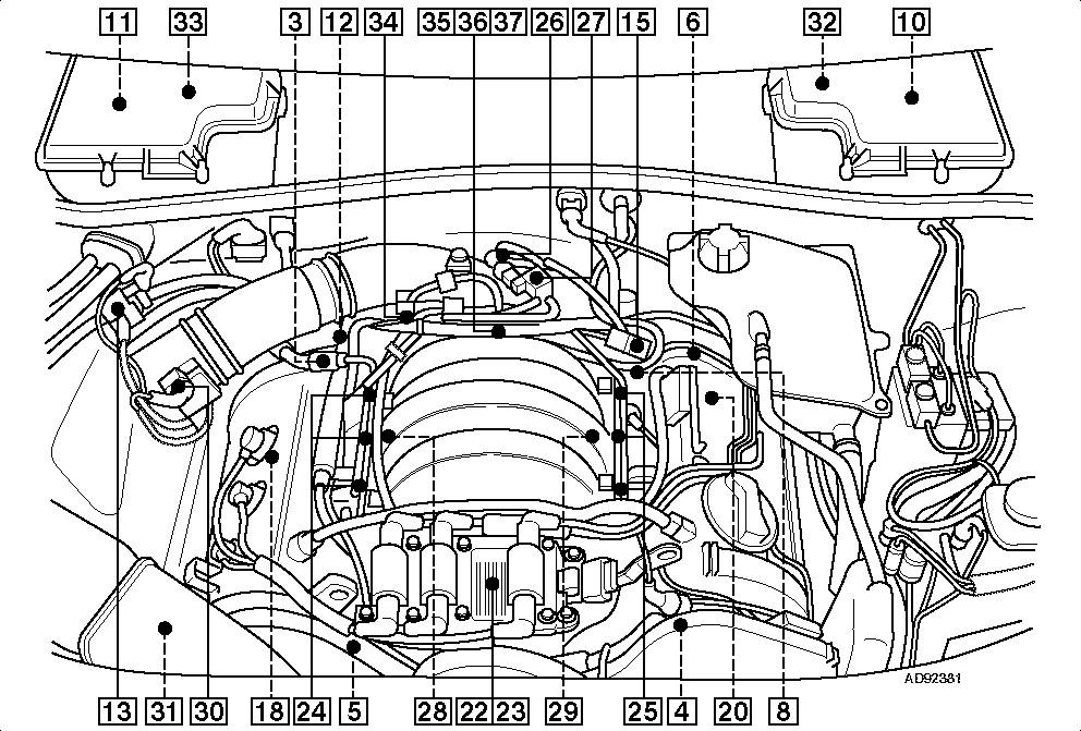
1 VOLKS CITY BEECH AVENUE CATTEDOWN PLYMOUTH PL4 0QQ Telephone: Fax: Accelerator pedal position (APP) sensor - above pedal 2 Brake pedal position (BPP) switch 1/2 - above pedal 3 Camshaft position (CMP) actuator 1 4 Camshaft position (CMP) actuator 2 5 Camshaft position (CMP) sensor 1 6 Camshaft position (CMP) sensor 2 7 Clutch pedal position (CPP) switch - above pedal 8 Crankshaft position (CKP) sensor 9 Data link connector (DLC) - fascia, driver's side 10 Engine control module (ECM) - LHD 11 Engine control module (ECM) - RHD 12 Engine coolant temperature (ECT) sensor 13 Evaporative emission (EVAP) canister purge valve 14 Fuel filter - tank exterior 15 Fuel pressure regulator 16 Fuel pump - in tank 17 Fuel pump relay - fascia relay plate 2 18 Heated oxygen sensor (HO2S) 1, bank 1 - before cat 19 Heated oxygen sensor (HO2S) 2, bank 1 - if fitted - after cat 20 Heated oxygen sensor (HO2S) 1, bank 2 - before cat 21 Heated oxygen sensor (HO2S) 2, bank 2 - if fitted - after cat 22 Ignition amplifier 23 Ignition coil 24 Injectors Injectors Intake air temperature (IAT) sensor 27 Intake manifold air control solenoid 28 Knock sensor (KS) 1 29 Knock sensor (KS) 2 30 Mass air flow (MAF) sensor 31 Secondary air injection (AIR) pump - if fitted 32 Secondary air injection (AIR) pump relay - if fitted - engine bay relay plate - LHD 33 Secondary air injection (AIR) pump relay - if fitted - engine bay relay plate - RHD 34 Secondary air injection (AIR) solenoid - if fitted 35 Throttle control unit 36 Throttle motor 37 Throttle motor position sensor 1/2 38 Vehicle speed sensor (VSS) - transmission
2
3 VOLKS CITY BEECH AVENUE CATTEDOWN PLYMOUTH PL4 0QQ Telephone: Fax: Notes Specified value Measured value Vehicle identification No. of cylinders Type 6/DOHC Capacity (Fiscal) cc 2393 Compression ratio :1 10,5 Suitable for unleaded petrol Yes Minimum octane rating RON 95 Ignition system Make Bosch Ignition system Type Motronic Ignition system Description Map-DIS Trigger location Cam / Crankshaft Fuel system Make Bosch Fuel system Type Motronic Fuel system Description MFI-s Air metering Type Mass Combined ignition and fuel ECM Yes Diagnostic socket Yes Ignition system Ignition coil Make Bosch Secondary resistance Ohm Firing order Tuning and emissions 47 Tuning conditions Ignition timing - basic BTDC Engine/rpm Not adjustable Ignition advance checks Engine/rpm ECM Controlled Idle speed rpm Not adjustable Oil temperature for CO test C 80 CO level at idle speed - tailpipe Vol. % CO 0,5 Max Not adjustable HC level at idle speed ppm 100 CO2 level at idle speed Vol. % CO2 14,5-16 O2 level at idle speed Vol. % O2 0,1-0,5 Increased idle speed for CO test rpm CO content at increased idle speed Vol. % 0,3 Lambda at increased idle λ 0,97-1,03 Spark plugs Spark plugs Original equipment NGK Spark plug Type BKR6EKUB Electrode gap mm 0,9-1,1 Spark plugs Make NGK Spark plug Type BKR6EKUB Electrode gap mm 0,9-1,1 Fuel system System pressure bar 3,8-4,2 Regulated pressure with vacuum bar 3,2-3,8 Engine coolant temperature (ECT) sensor Ohm/ C /80 Injector Ohm 13,5-15,5
4 Service checks and adjustments Valve clearance -INLET mm Hydraulic Valve clearance -EXHAUST mm Hydraulic Compression pressure bar 9-14 Oil pressure bar/rpm 2,0/2000 Radiator cap bar 1,4-1,6 Thermostat opens C 86 Lubricants and capacities Engine oil options Ambient temperature range All temperatures Engine oil grade SAE 0W/ Engine oil classification OEM VW Ambient temperature range All temperatures Engine oil grade SAE 5W/30, 5W/40 Engine oil classification OEM VW / Ambient temperature range -35 C > 15 C Engine oil grade SAE 5W/30, 5W/40 Engine oil classification OEM VW Ambient temperature range All temperatures Engine oil grade SAE 5W/50 Engine oil classification OEM VW Ambient temperature range All temperatures Engine oil grade SAE 10W/30, 10W/40 Engine oil classification OEM VW / Ambient temperature range -20 C > 15 C Engine oil grade SAE 10W/30, 10W/40 Engine oil classification OEM VW Ambient temperature range All temperatures Engine oil grade SAE 10W/50, 10W/60 Engine oil classification OEM VW Ambient temperature range -15 C > 40 C Engine oil grade SAE 15W/40, 15W/50 Engine oil classification OEM VW Ambient temperature range -15 C > 40 C Engine oil grade SAE 20W/40, 20W/50 Engine oil classification OEM VW Engine with filter(s) litres 5,7 Other lubricants and capacities Manual gearbox oil grade SAE 75W/90 Synthetic Manual gearbox litres 2,25-2, Automatic transmission fluid Type 255 Automatic transmission (drain & refill) litres 259 Differential oil grade - front SAE Synthetic 258 Differential front/at litres Differential oil grade - rear SAE 75W/90 Synthetic Differential rear litres 1,3 Cooling system litres 8,0 Brake fluid Type DOT 4 Brake fluid litres 1,0 Power steering fluid Type VW G Power steering fluid litres 0,85 Tightening torques Cylinder head instructions Cylinder head Renew bolts Yes Stage 1 Tighten 40 Nm Stage 2 Tighten 60 Nm Stage 3 Tighten 90
5 Stage 4 Tighten 90 Other engine tightening torques Main bearings Renew bolts/nuts Yes 178 Main bearings Stage 1 Big end bearings Renew bolts/nuts Yes 129 Big end bearings Stage 1 Oil pump to cylinder block 22 Nm 133 Sump bolts Sump drain bolt 30 Nm 79 Flywheel/driveplate Clutch to flywheel 20 Nm 72 Crankshaft pulley/damper centre bolt 62 Camshaft sprocket/gear 55 Nm Camshaft carrier/cap 10 Nm Camshaft/rocker cover 10 Nm Inlet manifold to cylinder head 10 Nm 62 Exhaust manifold to cylinder head 25 Nm 62 Exhaust downpipe to manifold 25 Nm Water pump 10 Nm Spark plugs 30 Nm Fuel rail 10 Nm Lambda sensor (Oxygen) 50 Nm Knock sensor (KS) 20 Nm Engine oil pressure switch 25 Nm Chassis tightening torques 92 Front hub 93 Rear hub Steering rack/box mounting 35 Nm 210 Steering track rod end 156 Brake caliper to carrier Front 25 Nm 155 Brake caliper carrier to hub Front 62 Brake caliper to carrier Rear 35 Nm Brake caliper carrier to hub Rear 95 Nm Road wheels 120 Nm Starting and charging Battery V/RC(Ah) 12 Brake disc and drum dimensions 183 Minimum disc thickness - ventilated Front 186 Minimum disc thickness Rear 8 mm Minimum pad thickness Front 2 mm Minimum pad thickness Rear 2 mm Air conditioning Air conditioning refrigerant Type R134a 127 Air conditioning refrigerant quantity grams 83 Air conditioning oil Type Air conditioning oil quantity cm³ 275±25 Autodata Note 47 Ignition timing, idle speed and CO level - with Cat and Lambda sensor Use VAG 1551 or equivalent equipment and initiate basic setting mode before checks. Autodata Note 275 Engine oil classification Longlife oil Autodata Note 257
6 Automatic transmission fluid type Tiptronic gearbox = G Multitronic gearbox (CVT) = G Autodata Note 255 Automatic transmission fluid - drain and refill Tiptronic gearbox = 2,6-3,0 litres Multitronic gearbox (CVT) = 4,5-5,0 litres Autodata Note 259 Differential oil grade - front Tiptronic gearbox = 75W/90 Multitronic gearbox (CVT) = G A2 Autodata Note 258 Differential oil - front Tiptronic gearbox = 0,8 litres Multitronic gearbox (CVT) = 1,3 litres Autodata Note 178 Main bearings Use new bolts. Horizontal bolts = 25 Nm Vertical bolts = 60 Nm Autodata Note 129 Big end bearings M8 = 30 Nm + 90 M8.5 = 40 Nm Autodata Note 133 Sump bolts Use new nuts. M6 = 10 Nm M7 = 15 Nm M10 = 45 Nm M8 = 22 Nm. Autodata Note 79 Flywheel/drive plate Use new bolts and tighten as follows: Flywheel = 60 Nm Drive plate = 60 Nm Autodata Note 72 Crankshaft pulley Use new bolts and tighten to 200 Nm Autodata Note 62
7 Use new bolts/nuts. Autodata Note 92 Front hub Use new bolts. M14 bolt = 115 Nm M16 bolt = 190 Nm Autodata Note 93 Rear hub - 4x4 Use new bolts. M14 bolt = 115 Nm M16 bolt = 190 Nm Rear hub assembly to axle = 60 Nm. Autodata Note 210 Steering track rod end Combination bolt = 7 Nm Use new self locking nut and tighten to 45 Nm. Autodata Note 156 Brake caliper to carrier FNR caliper = 30 Nm HP2 steel caliper = use new bolts and tighten to 25 Nm. Autodata Note 155 Brake caliper carrier to hub - front M12 = 130 Nm M14 = 200 Nm Twin piston caliper = 190 Nm Twin piston caliper (steel) = 200 Nm FN3 caliper = 120 Nm Brembo caliper = use new bolts and tighten to 110 Nm. Autodata Note 183 Minimum disc thickness FN3 caliper 15/16" wheels = 23 mm FNR-G60 caliper/hp 2 caliper 16" wheels = 28 mm Brembo caliper 18" wheel = 32 mm. Autodata Note 186 Minimum disc thickness Ventilated disc = 20 mm. Autodata Note 127 Refrigerant quantity = grams = grams : 20 mm condenser = grams : 16 mm condenser = grams

8 04.99 : 18 mm condenser = grams. Autodata Note 83 Oil type Zexel = G A2 Denso = G A2. Cylinder layout Tightening sequence
9 VOLKS CITY BEECH AVENUE CATTEDOWN PLYMOUTH PL4 0QQ Telephone: Fax: Important note Important note The intervals and procedures given are subject to alteration by the manufacturer at any time. Check the regularly updated Timing Belts section on our website to ensure that you are kept informed of any changes that may occur between issues of the Autodata CD. Timing belt replacement intervals Where possible the recommended intervals have been compiled from vehicle manufacturers' information. In a few instances no recommendation has been made by the manufacturer and the decision to replace the belt must be made from the evidence of a thorough examination of the condition of the existing belt. Apart from the visible condition of the belt, which is explained fully in the General Instructions/Toothed Timing Belts section, there are several other factors which must be considered when checking a timing belt: Is the belt an original or a replacement. When was the belt last replaced and was it at the correct mileage. Is the service history of the vehicle known. Has the vehicle been operated under arduous conditions which might warrant a shorter replacement interval. Is the general condition of other components in the camshaft drive, such as the tensioner, pulleys, and other ancillary components driven by the timing belt, typically the water pump, sound enough to ensure that the life of the replacement belt will not be affected. If the condition of the existing belt appears good, can you be satisfied that the belt will not fail before the next check or service is due. If the belt does fail, have you considered the consequences. If the engine is an INTERFERENCE type then considerable expensive damage may well be the result. The cost of replacing a belt as part of a routine service could be as little as 5 to 10% of the repair cost following a belt failure. Make sure your customer is aware of the consequences. If in doubt about the condition of the belt - RENEW it. Refer to the Toothed Timing Belts/Service Replacement section for further information relating to arduous or adverse operating conditions, inspection and service replacement. Replacement Interval Guide Replacement Interval Guide Audi recommend: A4 2,4/2,8 2002MY: Replacement every 120,000 kilometres (74,564 miles) - (tensioner pulley must also be replaced). A4 2,4/2,8 - except BDV 2002MY : Replacement every 80,000 miles - (tensioner pulley must also be replaced). A4 2,4 - BDV:
10 No manufacturer's recommended replacement interval. A6 2,4 2000MY: Replacement every 80,000 miles or 5 years - (tensioner pulley must also be replaced). A6/allroad 2,7 2000MY: Replacement every 80,000 miles or 5 years - (tensioner pulley, guide pulley and tensioner lever must also be replaced). A6/A8 2,8 2000MY: Replacement every 80,000 miles or 5 years - (tensioner pulley must also be replaced). A6 2,4 - except BDV 2001MY : Replacement every 80,000 miles or 8 years - (tensioner pulley must also be replaced). A6 2,4 - BDV 2001MY : Replacement every 115,000 miles. A6/allroad 2,7 2001MY : Replacement every 80,000 miles or 8 years - (tensioner pulley, guide pulley and tensioner lever must also be replaced). A6/A8 2,8 2001MY : Replacement every 80,000 miles or 8 years - (tensioner pulley must also be replaced). RS4 2,7: Replacement every 60,000 kilometres (37,282 miles) - (tensioner pulley, guide pulley and tensioner lever must also be replaced). S4 2,7: Replacement every 120,000 kilometres (74,564 miles) - (tensioner pulley, guide pulley and tensioner lever must also be replaced). NOTE: For some models the vehicle manufacturer publishes this information in kilometres. The conversion to miles is included for reference purposes only. The previous use and service history of the vehicle must always be taken into account. Check For Engine Damage Check For Engine Damage CAUTION: This engine has been identified as an INTERFERENCE engine in which the possibility of valve-to-piston damage in the event of a timing belt failure is MOST LIKELY to occur. A compression check of all cylinders should be performed before removing the cylinder head(s). Repair Times - hrs Repair Times - hrs All other transmissions Remove and install 3,85 01J gearbox Remove and install 3,85 Special Tools Special Tools Crankshaft locking pin - No Camshaft sprocket puller - No.T Camshaft sprocket holding tool - No Camshaft locking tool - No Viscous fan holder - No Viscous fan spanner - No Support guides - No Auxiliary drive belt tensioner locking pin - No.3204.
11 Special Precautions Special Precautions Disconnect battery earth lead. DO NOT turn crankshaft or camshaft when timing belt removed. Remove spark plugs to ease turning engine. Turn engine in normal direction of rotation (unless otherwise stated). DO NOT turn engine via camshaft or other sprockets. Observe all tightening torques. Removal Removal Remove: Engine cover. Engine undershield. Intercooler hoses (Turbo). A4/A6/S4: Remove: Front bumper. Air intake pipe between radiator support panel and air filter. Radiator support panel bolt [1]. A4/A6/S4: Install support guides No.3369 through holes in support panel [2]. A4/A6/S4: Remove radiator support panel bolts [3] & [4]. A4/A6/S4: Move radiator support panel into service position. Disconnect secondary air injection hose (if fitted). Remove: Viscous fan (LH thread). Use tool Nos.3212 & Auxiliary drive belt. Use tool No NOTE: Mark direction of rotation on belt with chalk if belt is to be reused. Remove: Auxiliary drive belt tensioner. Timing belt covers [5], [6] & [7]. Turn crankshaft clockwise until crankshaft pulley timing marks aligned [8]. Ensure large holes in locking plates of camshaft sprockets face in towards each other [9]. If large holes face outwards: Turn crankshaft one turn clockwise. Remove blanking plug from cylinder block. Fit locking pin No.3242 [10]. NOTE: TDC hole in crankshaft web must be aligned with blanking plug hole. Remove: Crankshaft pulley bolts [11]. Crankshaft pulley [12]. Viscous fan mounting bracket. NOTE: Two bolts of mounting bracket accessed through hole in pulley. Timing belt lower cover [13] Hold camshaft sprockets. Use tool No Slacken bolt of each camshaft sprocket approximately five turns [14]. Remove camshaft sprocket holding tool. Tool No Loosen camshaft sprockets from taper. Use tool No.T40001 [15]. Turn tensioner pulley slowly clockwise until holes in pushrod and tensioner body aligned. Use Allen key [16]. Lock tensioner pushrod in position with a 2 mm diameter pin [17]. Remove timing belt. NOTE: Mark direction of rotation on belt with chalk if belt is to be reused.
12 Installation Installation NOTE: Replace tensioner pulley (2,7/2,8 engines) Ensure crankshaft locking pin located correctly [10]. Lightly tighten bolt of each camshaft sprocket [14]. Ensure camshaft sprockets can turn freely but not tilt. Ensure large holes in locking plates of camshaft sprockets face in towards each other [9]. Fit timing belt in anti-clockwise direction, starting at crankshaft sprocket. Ensure belt is taut between sprockets on non-tensioned side. NOTE: If reusing old belt: Observe direction of rotation marks. Temporarily install camshaft locking tool No.3391 to camshaft sprockets [18]. Turn tensioner pulley clockwise as far as possible. Use Allen key [16]. Remove pin from tensioner body [17] to release pushrod. Remove Allen key. Install torque wrench to tensioner pulley [19]. Apply anti-clockwise torque of 15 Nm to tensioner pulley [20]. Remove torque wrench. Tighten bolt of each camshaft sprocket. Tightening torque: (A) 30 Nm [14]. Remove camshaft locking tool [18]. Tool No Hold camshaft sprockets. Use tool No Tighten bolt of each camshaft sprocket. Tightening torque: (B) 55 Nm [14]. Fit timing belt lower cover [13]. Install crankshaft pulley ensuring notches on pulley and hub are aligned [21]. Remove crankshaft locking pin [10]. Fit blanking plug to cylinder block. Install components in reverse order of removal. Tighten crankshaft pulley bolts to Nm [11].
13

14 VIN plate/engine code location
VOLKS CITY BEECH AVENUE CATTEDOWN PLYMOUTH PL4 0QQ
 VOLKS CITY BEECH AVENUE CATTEDOWN PLYMOUTH PL4 0QQ Telephone: 01752 667007 Fax: 01752 663399 Email: mail@volkscity.com Notes Specified value Measured value Vehicle identification No. of cylinders Type
VOLKS CITY BEECH AVENUE CATTEDOWN PLYMOUTH PL4 0QQ
 VOLKS CITY BEECH AVENUE CATTEDOWN PLYMOUTH PL4 0QQ Telephone: 01752 667007 Fax: 01752 663399 Email: mail@volkscity.com VAT Registration No.: 133 1580 01 1 Accelerator pedal position (APP) sensor 1/2 -
Yes Minimum octane rating RON 95. Cam/ Crankshaft Fuel System. Trigger location. Air metering Combined ignition and fuel ECM. Yes Diagnostic socket
 Vehicle identification No. of cylinders Type 4/DOHC Capacity (Fiscal) cc 1998 Compression ratio :1 11,0 Suitable for unleaded petrol Minimum octane rating RON 95 Ignition system Description Map-DI Trigger
VOLKS CITY BEECH AVENUE CATTEDOWN PLYMOUTH PL4 0QQ
 VOLKS CITY BEECH AVENUE CATTEDOWN PLYMOUTH PL4 0QQ Telephone: 01752 667007 Fax: 01752 663399 Email: mail@volkscity.com 1 Camshaft position (CMP) sensor 1 2 Camshaft position (CMP) sensor 2 3 Camshaft position
Timing belt replacement intervals
 Important note Important note The intervals and procedures given are subject to alteration by the manufacturer at any time. Check the regularly updated Timing Belts section on our website to ensure that
Timing belt replacement intervals
 Telephone: Fax: VAT Registration No.: Name: 1,8 66kw Manufacturer: Citroen Address: Model: Year: 1998 Registration: Tel - Private: Mileage: Tel - Business: Job number: Tel - Mobile Date Important note
Telephone: Fax: VAT Registration No.: Year: Registration:
 Telephone: Fax: VAT Registration No.: Name: Manufacturer: Renault Address: Model: Year: Registration: Tel - Private: Tel - Business: Mileage: Job number: Important note Important note The intervals and
Important note. Important Note. Telephone: Fax: VAT Registration No.:
 Telephone: Fax: VAT Registration No.: Important note NOTE: Timing belt check and replacement intervals are subject to change at any time. To ensure that you are using the most up-to-date and accurate information
Important note. Important Note. Telephone: Fax: VAT Registration No.:
 Telephone: Fax: VAT Registration No.: Important note NOTE: Timing belt check and replacement intervals are subject to change at any time. To ensure that you are using the most up-to-date and accurate information
Important note. Important Note. Telephone: Fax: VAT Registration No.:
 Telephone: Fax: VAT Registration No.: Important note NOTE: Timing belt check and replacement intervals are subject to change at any time. To ensure that you are using the most up-to-date and accurate information
LAND ROVER GROUP / Freelander I 2.5 V6 / 09/ /2007 / Terrain vehicle Country of manufacture GB Cubic capacity/power 2.
 1 Vehicle LAND ROVER GROUP / Freelander I 2.5 V6 / 09/2001-03/2007 / Terrain vehicle Country of manufacture GB Cubic capacity/power 2.5 / 130 kw Motor tag KV 6 MPI RB key LRG 48 Replacement Interval Guide
Telephone: Fax: VAT Registration No.:
 Telephone: Fax: VAT Registration No.: Terminal side Wire side Component/circuit description ECM pin Signal Condition Typical value Oscilloscope setting (Suggested settings - Voltage/time per division)
Telephone: Fax: VAT Registration No.:
 Telephone: Fax: VAT Registration No.: Name: Manufacturer: Ford Address: Model: Year: 1994 Registration: Tel - Private: Tel - Business: Mileage: Job number: Terminal side Wire side Component/circuit description
Timing Chain - Renew ( )
") «Scorpio '95 Table of Contents» «Section 21: Engine» «Subsection 21-05: 2,9 V6 24V Cosworth Engine» «REMOVAL AND INSTALLATION» Timing Chain - Renew (21 314 0) Special Tools 21-140-01Adaptor for 21-140
«Scorpio '95 Table of Contents» «Section 21: Engine» «Subsection 21-05: 2,9 V6 24V Cosworth Engine» «REMOVAL AND INSTALLATION» Timing Chain - Renew (21 314 0) Special Tools 21-140-01Adaptor for 21-140
Timing Chain Renew ( ) Renew. Section Title. Special Tools. Proprietary Tools Scraper Engine support bar
 Renew. Section Title. Special Tools. Proprietary Tools Scraper Engine support bar") Timing Chain Renew ( 34 0) Special Tools 40 400 40 Engine support bar 40 0 Adaptor for -40 40 03 Adaptor for -40 Proprietary Tools Scraper Workshop Equipment Transmission jack Materials Cable ties Sealer
Timing Chain Renew ( 34 0) Special Tools 40 400 40 Engine support bar 40 0 Adaptor for -40 40 03 Adaptor for -40 Proprietary Tools Scraper Workshop Equipment Transmission jack Materials Cable ties Sealer
Diagnostic Trouble Code (DTC) memory, checking and erasing
 memory, checking and erasing") Page 1 of 49 01-12 Diagnostic Trouble Code (DTC) memory, checking and erasing Check DTC Memory (function 02) - Connect VAS5051 tester Page 01-7 and select vehicle system "01 - Engine electronics". Engine
Page 1 of 49 01-12 Diagnostic Trouble Code (DTC) memory, checking and erasing Check DTC Memory (function 02) - Connect VAS5051 tester Page 01-7 and select vehicle system "01 - Engine electronics". Engine
LAND ROVER GROUP / Freelander I 2.0 Diesel / 09/ /2003 / Terrain vehicle Country of manufacture GB Cubic capacity/power 2.
 Vehicle LAND ROVER GROUP / Freelander I 2.0 Diesel / 09/1997-09/2003 / Terrain vehicle Country of manufacture GB Cubic capacity/power 2.0 / 70-72 kw Motor tag TCie 17N,18N RB key LRG 46 Replacement Interval
Lower Intake Manifold Replacement
 Lower Intake Manifold Replacement Removal Procedure 1. Turn OFF all the lamps and the accessories. 2. Ensure the ignition switch is in the OFF position. 3. Disconnect the negative battery cable from the
PEUGEOT / 206 CC 1.6i 16V / 09/ /2007 / Cabriolet Country of manufacture EU Cubic capacity/power 1.6 / 80 kw Motor tag RB key PEU 814
 1 Vehicle PEUGEOT / 206 CC 1.6i 16V / 09/2000-03/2007 / Cabriolet Country of manufacture EU Cubic capacity/power 1.6 / 80 kw Motor tag NFU RB key PEU 814 Replacement Interval Guide Peugeot recommend: 206:
Motronic ignition system, servicing
 Page 1 of 25 28-2 Motronic ignition system, servicing Note: Motronic Engine Control Module (ECM) J220* with connector page 24-9, item 16. 1 - Highvoltage ignition cable Ignition secondary circuit Check
Cylinder head, removing and
 Page 1 of 35 15-2 Cylinder head, removing and installing Note: Replace cylinder head bolts. Always replace self-locking nuts, bolts as well as gaskets and O-rings. After installing a replacement cylinder
Zoom and Print Options
 Vehicle» Engine, Cooling and Exhaust» Engine» Service and Repair» Removal and Replacement» Engine Replacement Engine Replacement ^ Tools Required - J 38185 Hose Clamp Pliers Removal Procedure 1. Remove
Engine Dismantle and Assemble ( )
") Engine Dismantle and Assemble ( 34 8) Special Tools 5 053 Slide hammer 47 Vibration damper remover 47 5053 00 Splined head socket, cylinder head bolts 87 Mounting stand with geared drive 00 059C Installer
Engine Dismantle and Assemble ( 34 8) Special Tools 5 053 Slide hammer 47 Vibration damper remover 47 5053 00 Splined head socket, cylinder head bolts 87 Mounting stand with geared drive 00 059C Installer
Diagnostic Trouble Code (DTC) table
 table") Page 1 of 40 01-19 Diagnostic Trouble Code (DTC) table Note: When malfunctions occur in monitored sensors or components, Diagnostic Trouble Codes (DTCs) are stored in DTC memory with a description of the
Page 1 of 40 01-19 Diagnostic Trouble Code (DTC) table Note: When malfunctions occur in monitored sensors or components, Diagnostic Trouble Codes (DTCs) are stored in DTC memory with a description of the
2.8 Liter VR6 2V Fuel Injection & Ignition, Engine Code(s): AAA m.y
: AAA m.y") 2.8 Liter VR6 2V Fuel Injection & Ignition, Engine Code(s): AAA m.y. 1996-1997 01 - On Board Diagnostic (OBD) On Board Diagnostic (OBD II) Malfunction Indicator Lamp (MIL) On Board Diagnostic (OBD II),
2.8 Liter VR6 2V Fuel Injection & Ignition, Engine Code(s): AAA m.y. 1996-1997 01 - On Board Diagnostic (OBD) On Board Diagnostic (OBD II) Malfunction Indicator Lamp (MIL) On Board Diagnostic (OBD II),
Audi > B4 > Liter V6 2V Engine Mechanical, Engine Code(s): AAH, AFC 10 Engine Assembly
: AAH, AFC 10 Engine Assembly") Audi > B4 > 1993 1995 2.8 Liter V6 2V Engine Mechanical, Engine Code(s): AAH, AFC 10 Engine Assembly Removing The engine is removed from above, after being separated from the transmission. Note: All tie
Audi > B4 > 1993 1995 2.8 Liter V6 2V Engine Mechanical, Engine Code(s): AAH, AFC 10 Engine Assembly Removing The engine is removed from above, after being separated from the transmission. Note: All tie
Valve gear, servicing
 Page 1 of 62 15-1 Valve gear, servicing WARNING! Do not re-use any fasteners that are worn or deformed in normal use. Some fasteners are designed to be used only once, and are unreliable and may fail if
Engine management/transmission
 MAZDA Model: 323 (BG) 323 Estate 1,6/4x4 (BW) 323 (BA/BJ) 626/MX-6 626/Estate Xedos 6/9 MX-3/MX-5 Year: 1989-00 Engina code: BP, BP-DOHC, B3, B3E, B6, B6-SOHC, B6-DOHC, B6E,FP, FS, KF, KJ, KL K8, RF, RF-CX,
Audi A4 Current Flow Diagram No. 44 / 1 Edition
 Page 1 of 16 Audi A4 Current Flow Diagram No. 44 / 1 Edition 05.2003 1.8 l - Fuel injection engine (110 kw - Motronic - 4 cylinder), engine code AVJ from model year 2002 1.8 l - Fuel injection engine (120
ENGINE - V8. Seal - crankshaft - rear. Refit 1. Ensure both seal location and running surface on crankshaft are clean.
 REPAIRS Seal - crankshaft - rear 1. Ensure both seal location and running surface on crankshaft are clean. 1. Automatic gearbox models: converter drive plate. ENGINE - V8, REPAIRS, Plate - drive - automatic.
2003 Taurus/Sable Workshop Manual
 Page 1 of 24 SECTION 303-01A: Engine 3.0L (2V) ASSEMBLY 2003 Taurus/Sable Workshop Manual Engine Special Tool(s) Piston Ring Compressor 303- D032 (D81L-6002-C) Camshaft Bearing Set 303-017 (T65L-6250-A)
FUEL PUMP CAMSHAFT TIMING CHECK
 PUBLISHED: 26-FEB-2018 2010.0 RANGE ROVER SPORT (LS), 303-01 ENGINE - V8 S/C 5.0L PETROL FUEL PUMP CAMSHAFT TIMING CHECK (G1473740) GENERAL PROCEDURES 19.90.16 HIGH PRESSURE FUEL TIMING CHECK 5000 CC,
Motronic September 1998
 The Motronic 1.8 engine management system was introduced with the 1992 Volvo 960. The primary difference between this Motronic system and the previous generation of Volvo LH-Jetronic engine management
Powertrain DTC Summaries EOBD
 Powertrain DTC Summaries Quick Reference Diagnostic Guide Jaguar X-TYPE 2.0 L 2002.25 Model Year Refer to page 2 for important information regarding the use of Powertrain DTC Summaries. Jaguar X-TYPE 2.0
FUEL PUMP CAMSHAFT TIMING ADJUSTMENT (G )
") PUBLISHED: 10-OCT-2017 2010.0 RANGE ROVER SPORT (LS), 303-01 ENGINE - V8 S/C 5.0L PETROL FUEL PUMP CAMSHAFT TIMING ADJUSTMENT (G1473741) GENERAL PROCEDURES 19.90.17 HIGH PRESSURE FUEL TIMING CHECK AND
PUBLISHED: 10-OCT-2017 2010.0 RANGE ROVER SPORT (LS), 303-01 ENGINE - V8 S/C 5.0L PETROL FUEL PUMP CAMSHAFT TIMING ADJUSTMENT (G1473741) GENERAL PROCEDURES 19.90.17 HIGH PRESSURE FUEL TIMING CHECK AND
Engine, disassembling and
 Page 1 of 38 13-1 Engine, disassembling and assembling Lock carrier, moving into service position Special tools and equipment 3369 support tool 1 - Bolts 2 - Bolts 3 - Bolts 4 - Bolts 5 - Bore 45 Nm (33
Telephone: Fax: VAT Registration No.:
 Telephone: Fax: VAT Registration No.: Name: Manufacturer: Ford Address: Model: Scorpio Year: 1991 Registration: Tel - Private: Tel - Business: Mileage: Job number: Terminal side Wire side Component/circuit
Diagnostic Trouble Code (DTC) List - Vehicle
 List - Vehicle") Document ID# 850406 2002 Pontiac Firebird Diagnostic Trouble Code (DTC) List - Vehicle DTC DTC 021 and/or 031 DTC 022 and/or 032 DTC 023 or 033 DTC 24/34 DTC 025 and/or 035 DTC 041 DTC 042 DTC 043 DTC
Document ID# 850406 2002 Pontiac Firebird Diagnostic Trouble Code (DTC) List - Vehicle DTC DTC 021 and/or 031 DTC 022 and/or 032 DTC 023 or 033 DTC 24/34 DTC 025 and/or 035 DTC 041 DTC 042 DTC 043 DTC
REMOVAL & INSTALLATION
 REMOVAL & INSTALLATION TIMING BELT Removal 1. Disconnect negative battery cable. Rotate engine clockwise and position cylinder No. 1 on TDC of compression stroke. Ensure "O" mark on crankshaft pulley aligns
Intake Components 1117
 Item Part Number Description 1 W705654 Bolt 2 N807309 Bolt (2 req'd) 3 9F460 Bracket 4 N807071 Bolt (5 req'd) 5 9A448 Intake manifold (upper) 6 9E498 Vacuum harness 7 9F792 Fuel injection supply manifold
Powertrain DTC Summaries OBD II
 Powertrain DTC Summaries Quick Reference Diagnostic Guide Jaguar X-TYPE 2.5L and 3.0L 2002 Model Year Revised January, 2002: P0706, P0731, P0732, P0733, P0734, P0735, P0740, P1780 POSSIBLE CAUSES Revised
COMPONENT LOCATOR > DISASSEMBLED VIEWS
 Page 1 of 45 2006 Pontiac Grand Prix 3.8L Eng Base Service Manual: ENGINE MECHANICAL - 3.8L COMPONENT LOCATOR > DISASSEMBLED VIEWS Fig 1: Engine Block Component Views Callout Component Name 100 Engine
Toothed belt, removing and installing
 Toothed belt, removing and installing Special Tools and Equipment ^ 3212 spanner wrench ^ 3387 pin wrench ^ T40011 pin ^ T40026 locking pin ^ T40028 socket ^ T40030 camshaft adjuster gauge Removing Lock
Chapter 5 Part B: Ignition system - transistorised type
 5B 1 Chapter 5 Part B: Ignition system - transistorised type Contents Coil - testing........................................... 9 Distributor - overhaul..................................... 7 Distributor
REMOVAL & INSTALLATION
 REMOVAL & INSTALLATION NOTE: For reassembly reference, label all electrical connectors, vacuum hoses and fuel lines before removal. Also place mating marks on engine hood and other major assemblies before
Technical data. Part Thread (mm) Nm ±10% Tolerance Sidestand
 Nm ±10% Tolerance Sidestand") section 3 - Torque settings Frame torque settings Sidestand Stand sensor bolt 5 Pre-applied threadlocker Stand plate fixing screw M10x25 43 Pre-applied threadlocker Side stand fastening pin Side stand
section 3 - Torque settings Frame torque settings Sidestand Stand sensor bolt 5 Pre-applied threadlocker Stand plate fixing screw M10x25 43 Pre-applied threadlocker Side stand fastening pin Side stand
General Specifications
 General Specifications Engine Data General Engine management EEC V/SEFI Emission standard 96 EEC Engine code N3A Firing order 1-3-4-2 Bore mm 86,0 Stroke mm 86,0 Cubic capacity cc 1998 Compression ratio
ASSEMBLY. Engine. Special Tool(s) Installer, Crankshaft Vibration Damper (T74P-6316-B) Special Tool(s)
 Installer, Crankshaft Vibration Damper (T74P-6316-B) Special Tool(s)") 303-01A-1 ASSEMBLY Engine Special Tool(s) Tensioner, Timing Chain 303-571 (T97T-6K254-A) Special Tool(s) 303-01A-1 Installer, Crankshaft Vibration Damper 303-102 (T74P-6316-B) Holding Tool, Camshaft Sprocket
303-01A-1 ASSEMBLY Engine Special Tool(s) Tensioner, Timing Chain 303-571 (T97T-6K254-A) Special Tool(s) 303-01A-1 Installer, Crankshaft Vibration Damper 303-102 (T74P-6316-B) Holding Tool, Camshaft Sprocket
Motronic injection system,
 Page 1 of 78 24-1 Motronic injection system, servicing Safety precautions If special testing equipment is required during road test, note the following: WARNING! Scan tools and testing devices must always
Cylinder Head Replacement
 CYLINDER HEAD REPLACEMENT (EN... CYLINDER HEAD REPLACEMENT (ENGINE MECHANICAL - 1.6L) Document ID# 1430093 Cylinder Head Replacement Tools Required J 45059 Angle Meter KM-470-B Angular Torque Gauge J 42492-A
Service Bulletin. DTC Detection Item Associated Monitor
 Service Bulletin 03-010 Applies To: All OBD II equipped models except SLX March 29, 2003 OBD II DTCs and Their Associated Monitors This is a list of all DTCs for all OBD II models. No one model has all
Powertrain DTC Summaries EOBD
 Powertrain DTC Summaries Quick Reference Diagnostic Guide Jaguar S-TYPE V6, V8 N/A and V8 SC 2002.5 Model Year Refer to pages 2 9 for important information regarding the use of Powertrain DTC Summaries.
Engine, disassembly and
 Page 1 of 13 13-1 Engine, disassembly and assembly Ribbed belt, removing and installing Removing - Remove noise insulation -arrows-. - Remove bumper Repair Manual, Body Exterior, Repair Group 63 - Move
Auto Diagnosis Test #7 Review
 Auto Diagnosis Test #7 Review Your own hand written notes may be used for the 1 st 10 minutes of the test Based on Chapters 25, 26, 32, 33, 34 and Lab Demonstrations Auto Diagnosis Test #7 Review Your
14-6. TSB Revision ENGINE COOLING ON-VEHICLE SERVICE
 14-6 RADIATOR CAP DRAIN PLUG ENGINE COOLING ON-VEHICLE SERVICE When removing the radiator cap, use care to avoid contact with hot coolant or steam Place a shop towel over the cap and turn the cap counterclockwise
2003 Nissan-Datsun Truck Frontier 4WD V6-3.3L (VG33E)
") 1 of 15 8/7/2016 2:34 PM 2003 Nissan-Datsun Truck Frontier 4WD V6-3.3L (VG33E) Vehicle» Engine, Cooling and Exhaust» Engine» Cylinder Head Assembly» Service and Repair» Removal and Installation 2 of 15
1 of 15 8/7/2016 2:34 PM 2003 Nissan-Datsun Truck Frontier 4WD V6-3.3L (VG33E) Vehicle» Engine, Cooling and Exhaust» Engine» Cylinder Head Assembly» Service and Repair» Removal and Installation 2 of 15
REMOVAL & INSTALLATION
 REMOVAL & INSTALLATION CAUTION: This application is an interference engine. Do not rotate camshaft or crankshaft when timing belt is removed, or engine damage may occur. TIMING BELT Removal 1. Raise and
SOUL GDI REPAIR AND MAINTENANCE
 SOUL 2013-1.6 GDI REPAIR AND MAINTENANCE (First Numbers are page number within section - Numbers in parenthesis are overall document page) GENERAL INFORMATION (23 PAGES) 01-07 (01-07): Identification Number
Tech Talk. Timing Belt 6VD1/6VE1
 Holden DOHC V6 Frontera 6VD1 3.2L 1999 2004 Jackaroo 6VE1 3.5L 1998 2004 Rodeo TF 6VD1 3.2L 1998 2003 Rodeo RA 6VE1 3.5L 2003 2005 Important: Read through all the instructions before proceeding with the
DISASSEMBLY Procedure revision date: 11/22/2001
 Page 1 of 31 Evan Groenke From: Daniel Lelovic [dlelovic@rogers.com] Sent: May 8, 2005 12:06 PM To: 'Evan Groenke' Subject: 2.5 L Engine Disassembly SECTION 303-01B: Engine 2.5L 2000 Contour/Mystique Workshop
Disconnect the breather tube from the air cleaner outlet duct.
 Disconnect the breather tube from the air cleaner outlet duct. Disconnect the IAT sensor harness connector. Remove the air cleaner outlet duct retaining wingnut. Separate the air cleaner outlet duct from
 http://www.prodemand.com/print/index?content=tabs&module=true&tab=true&terms=tr... Page of //0 00 Chevrolet Silverado.L Eng 00 Service Manual: WIRING DIAGRAMS - 00 Print Date: //0 ENGINE PERFORMANCE Tip:
ASSEMBLY Procedure revision date: 11/22/2001
 Page 1 of 39 Evan Groenke From: Daniel Lelovic [dlelovic@rogers.com] Sent: May 8, 2005 12:08 PM To: 'Evan Groenke' Subject: 2.5L Engine Re-assembly SECTION 303-01B: Engine 2.5L 2000 Contour/Mystique Workshop
DISASSEMBLY. Engine. CAUTION: Remove the cylinder heads before removing the crankshaft. Failure to do so can result in engine damage.
 303-01A-1 DISASSEMBLY Engine Special Tool(s) Remover, Crankshaft Vibration Damper 303-101 (T74P-3616-A) Special Tool(s) Crankshaft Socket 303-674 303-01A-1 Remover, Crankshaft Vibration Damper 303-773
Valve + Valve Guide Unit: mm (in) Item Standard Limit Valve diam. IN (1.20) EX (1.06) Valve clearance (when cold)
 Item Standard Limit Valve diam. IN (1.20) EX (1.06) Valve clearance (when cold)") Model: LT-A400FL9 P-17, 24, 28,03 Date: Feb. 12, 2018 SERVICE DATA Valve + Valve Guide Valve diam. IN. 30.6 (1.20) EX. 27.0 (1.06) Valve clearance (when cold) IN. 0.05 0.10 (0.002 0.004) EX. 0.22 0.27
Model: LT-A400FL9 P-17, 24, 28,03 Date: Feb. 12, 2018 SERVICE DATA Valve + Valve Guide Valve diam. IN. 30.6 (1.20) EX. 27.0 (1.06) Valve clearance (when cold) IN. 0.05 0.10 (0.002 0.004) EX. 0.22 0.27
VALVE CLEARANCE (K3-VE)
") ENGINE MECHANICAL VALVE CLEARANCE (K3-VE) 25 ENGINE MECHANICAL VALVE CLEARANCE (K3-VE) INSPECTION 1. DISCONNECT NEGATIVE BATTERY TERMINAL (See page RS-164.) 2. ROVE ENGINE UNDER COVER 3. DRAIN ENGINE COOLANT
ENGINE MECHANICAL VALVE CLEARANCE (K3-VE) 25 ENGINE MECHANICAL VALVE CLEARANCE (K3-VE) INSPECTION 1. DISCONNECT NEGATIVE BATTERY TERMINAL (See page RS-164.) 2. ROVE ENGINE UNDER COVER 3. DRAIN ENGINE COOLANT
General Specifications
 General Specifications General Engine management EEC V Emission standard 96 EC Engine code Y5A Firing order 1 3 4 2 Bore mm 89,6 Stroke mm 91 Cubic capacity cc 2295 Compression ratio 10,0:1 Compression
3/6/2017 Timing Chain Service and Repair, Removal and Replacement: Valve Timing, Installing and Adjusting
 Valve timing, adjusting Special tools and equipment - T10068 Camshaft bar - T10069 Counter support - VAG 1331 Torque wrench (5-50 Nm) - VAG 1332 Torque wrench (40-200 Nm) - AMV 174 004 01 Sealing compound
Cooling system components, removing and installing
 Page 1 of 40 19-1 Cooling system components, removing and installing WARNING! The cooling system is pressurized when the engine is warm. When opening the expansion tank, wear gloves and other appropriate
2.2L 4-CYL - VIN [S]
![2.2L 4-CYL - VIN [S]](/thumbs/72/67564355.jpg "2.2L 4-CYL - VIN [S]") 2.2L 4-CYL - VIN [S] 1994 Toyota Celica 1994 ENGINES Toyota 2.2L 4-Cylinder Celica NOTE: For repair procedures not covered in this article, see ENGINE OVERHAUL PROCEDURES - GENERAL INFORMATION article
2.2L 4-CYL - VIN [S] 1994 Toyota Celica 1994 ENGINES Toyota 2.2L 4-Cylinder Celica NOTE: For repair procedures not covered in this article, see ENGINE OVERHAUL PROCEDURES - GENERAL INFORMATION article
Powertrain DTC Summaries EOBD
 Powertrain DTC Summaries Quick Reference Diagnostic Guide Jaguar X-TYPE 2.5L and 3.0L 2001.5 Model Year Revised January, 2002: P0706, P0731, P0732, P0733, P0734, P0735, P0740, P1780 POSSIBLE CAUSES Revised
Torque Guidelines (Z 22 SE)
") Page 1 of 14 Torque Guidelines (Z 22 SE) No. Designation Nm 1 Retaining bolts, coolant pump sprocket to coolant pump 2 Retaining bolts, balancer shaft timing chain guide rail to 3 Retaining bolts, balancer
Page 1 of 14 Torque Guidelines (Z 22 SE) No. Designation Nm 1 Retaining bolts, coolant pump sprocket to coolant pump 2 Retaining bolts, balancer shaft timing chain guide rail to 3 Retaining bolts, balancer
Telephone: Fax: VAT Registration No.:
 Telephone: Fax: VAT Registration No.: K143 AC compressor clutch relay X88 AC connector S63 AC refrigerant pressure switch S341 AC refrigerant triple pressure switch A16 Anti-lock braking system (ABS) control
DTC Summaries. NipponDenso V12 Engine Management
 DTC Summaries NipponDenso V12 Engine Management OBD II MONITORING CONDITIONS: When testing for DTC reoccurrence, it can be determined if the Service Drive Cycle was of sufficient length by performing a
51. absolute pressure sensor
 51. absolute pressure sensor Function The absolute pressure sensor measures the atmospheric pressure. Specifications supply voltage: 5 V output voltage sea level: 3.5-4.5 V output voltage at 2000m: 2.5-3.5
1997 Volvo 850 GLT. Fig. 2: Removing Drive Shaft, Engine Mount Bolt & Torque Arm (5-Cylinder) Courtesy of VOLVO CARS OF NORTH AMERICA.
 Courtesy of VOLVO CARS OF NORTH AMERICA.") Fig. 2: Removing Drive Shaft, Engine Mount Bolt & Torque Arm (5-Cylinder) 4. Remove front exhaust pipe nuts and springs. Remove front exhaust pipe bolts. Disconnect speedometer. Remove engine mounting
Fig. 2: Removing Drive Shaft, Engine Mount Bolt & Torque Arm (5-Cylinder) 4. Remove front exhaust pipe nuts and springs. Remove front exhaust pipe bolts. Disconnect speedometer. Remove engine mounting
ARTICLE BEGINNING INTRODUCTION IGNITION SYSTEM CAMSHAFT POSITION (CMP) SENSOR DISTRIBUTOR
 SENSOR DISTRIBUTOR") Article Text Thursday, August 19, 1999 11:40PM ARTICLE BEGINNING 1996 ENGINE PERFORMANCE Volkswagen Removal, Overhaul & Installation - Gasoline Cabrio, Golf III, GTI, Jetta III, Passat CAUTION: When battery
Article Text Thursday, August 19, 1999 11:40PM ARTICLE BEGINNING 1996 ENGINE PERFORMANCE Volkswagen Removal, Overhaul & Installation - Gasoline Cabrio, Golf III, GTI, Jetta III, Passat CAUTION: When battery
2002 Crown Victoria/Grand Marquis Workshop Manual
 Page 1 of 24 SECTION 303-01: Engine 2002 Crown Victoria/Grand Marquis Workshop Manual INSTALLATION Procedure revision date: 01/02/2003 Cylinder Heads Special Tool(s) Installer, Crankshaft Vibration Damper
Section 2 Engine. kw at rps hp / rpm Nm / rpm. Engine code 68 Engine management system Denso Bosch ME 7 No. of cylinders 5 5
 S40 ( 04- ) Section 2 Engine Section 2 Engine Group 20 General data engines Performance and other data, petrol engines: Engine type: ( Geometric compression ratio) B5254T3 (9.0:1) Other general data Engine
 http://www.prodemand.com/print/index?content=tabs&module=true&tab=true&terms=t... Page of // 0 Chevrolet Traverse.L Eng LT Service Manual: WIRING DIAGRAMS Print Date: // ENGINE PERFORMANCE >.L VIN D Fig
1995 Mitsubishi Montero LS. Ensure timing marks are aligned. Mark timing belt direction of rotation.
 TIMING BELT NOTE: Ensure timing marks are aligned. Mark timing belt direction of rotation. Removal 1. Disconnect negative battery cable. Drain engine coolant. Remove engine coolant reservoir tank, fan
The 2.0L FSI Turbocharged Engine Design and Function Self-Study Program Course Number
 www.golfmkv.com The 2.0L FSI Turbocharged Engine Design and Function Self-Study Program Course Number 821503 www.golfmkv.com Volkswagen of America, Inc. Volkswagen Academy Printed in U.S.A. Printed 08/2005
Disconnect negative battery cable and remove coolant bottle cap.
 1 of 16 3/25/2012 10:18 AM ools Required SA9105E 3-Bar Engine Support Fixture SA9412G Constant Force Clamp Pliers SA9127E Gage Bar Set Powertrain Assembly Removal Caution: Do not allow smoking or the use
Cylinder Head Removal
 2006 Odyssey Cylinder Head Removal Report a problem with this article NOTE: Use fender covers to avoid damaging painted surfaces. To avoid damaging the wires and terminals, unplug the wiring connectors
ENGINE <6G7> Click on the applicable bookmark to selected the required model year.
 ENGINE Click on the applicable bookmark to selected the required model year. 11A-2 ENGINE CONTENTS GENERAL INFORMATION... 3 SERVICE SPECIFICATIONS... 3 SEALANT... 4 SPECIAL TOOLS... 4 ON-VEHICLE
7. Remove the starter motor. Refer to Starter Motor Replacement (2.2L) or Starter Motor Replacement (4.3L).
 or Starter Motor Replacement (4.3L).") 1 of 9 1/5/2013 6:40 PM Removal Procedure 1. Disconnect the battery negative cable. Refer to Battery Replacement. 2. Remove the hood. Refer to Hood Replacement. 3. If the vehicle is equipped with a manual
1 of 9 1/5/2013 6:40 PM Removal Procedure 1. Disconnect the battery negative cable. Refer to Battery Replacement. 2. Remove the hood. Refer to Hood Replacement. 3. If the vehicle is equipped with a manual
Master Engine Timing Tool Set
 Master Engine Timing Tool Set Ford K 10551 www.kamasatools.com Pack Layout AC V O B C U D M Z S J W W N F Y K/L Q T AD P A H R AB AA E X G I Component identity Part No. OEM Ref Description A 23002-45D
Cylinder Head. Special Tool(s) Compressor, Valve Spring (T93P-6565-AR) Heavy Duty Floor Crane or equivalent
 Compressor, Valve Spring (T93P-6565-AR) Heavy Duty Floor Crane or equivalent") SECTION 303-01C: Engine 5.4L (4V) 2009 Mustang Workshop Manual INSTALLATION Procedure revision date: 04/03/2009 Cylinder Head Special Tool(s) Compressor, Valve Spring 303-452 (T93P-6565-AR) Heavy Duty
SECTION 303-01C: Engine 5.4L (4V) 2009 Mustang Workshop Manual INSTALLATION Procedure revision date: 04/03/2009 Cylinder Head Special Tool(s) Compressor, Valve Spring 303-452 (T93P-6565-AR) Heavy Duty
General Specifications
 General Specifications Engine Data Description Litres Engine management EEC V/SFI Emission standard 96 EEC Engine code NSD Firing order 1-3 - 4-2 Bore mm 86,0 Stroke mm 86,0 Cubic capacity cm 3 1998 Compression
Disconnect the APP sensor harness connector. See Fig. 4. Remove the accelerator pedal mounting nuts. Remove the APP assembly.
 ENGINE CONTROLS - REMOVAL, OVERHAUL & INSTALLATION - 6.6L DIESEL... Page 1 of 41 FUEL SYSTEMS ACCELERATOR PEDAL POSITION SENSOR Removal & Installation Disconnect the APP sensor harness connector. See Fig.
TIGHTENING TORQUE CHART For other nuts and bolts not listed in the preceding page, refer to this chart:
 TIGHTENING TORQUE ENGINE ITEM N m kgfm lbft Cylinder head cover bolt 14 1.4 10.0 Spark plug 11 1.1 8.0 Cylinder head bolt (M10) 47 4.7 18.0 (M6) 10 1.0 7.0 Cylinder bolt 10 1.0 7.0 Camshaft journal holder
 Page 1 of 9 SECTION 303-01B: Engine 2.0L SPI 2002 Focus Workshop Manual ASSEMBLY Procedure revision date: 12/14/2000 Engine Special Tool(s) Crankshaft Rear Seal Pilot 303-329 (T88P-6701-B2) Crankshaft
16A. STARTING - CHARGING Starter: Removal - Refitting REFITTING 16A-11 K4M II - REMOVAL OPERATION III - FINAL OPERATION
 STARTING - CHARGING Starter: Removal - Refitting 16A K4M II - REMOVAL OPERATION III - FINAL OPERATION JR5 a Clip: -the gearbox control cable sleeve stops on the gearbox, - the control cables onto the gearbox.
1983 BMW 320i. 1.8L 4-CYL 1983 Engines - 1.8L 4-Cylinder Engines - 1.8L 4-Cylinder
 ENGINE IDENTIFICATION 1.8L 4-CYL 1983 Engines - 1.8L 4-Cylinder For engine repair procedures not covered in this article, see ENGINE OVERHAUL PROCEDURES - GENERAL INFORMATION article in the GENERAL INFORMATION
Removing and installing cylinder head Removing, installing and tensioning toothed belt
 Page 1 of 10 Removing and installing cylinder head Removing, installing and tensioning toothed belt Special tools, workshop equipment, test and measuring appliances and auxiliary items required 3359 Locking
DESCRIPTION AND OPERATION
 303-01B-10 Engine 3.0L 303-01B-10 DESCRIPTION AND OPERATION Upper Engine Components G72932 en 303-01B-11 Engine 3.0L 303-01B-11 DESCRIPTION AND OPERATION (Continued) Item Part Number Description 1 9H589
TECHNICAL BULLETIN Engine Vibration/Noise Above 1000 RPM Oil Pump Resonance Install Revised Oil Pump SERVICE DATE MODEL 2002 MY.
 SERVICE V8 XJ Series DATE 12/02 TECHNICAL BULLETIN Engine Vibration/Noise Above 1000 RPM Oil Pump Resonance Install Revised Oil Pump 100-21 MODEL 2002 MY V8 XJ Series VIN F44114 - F55936 Issue: Some 2002
Engine. Special Tool(s) Adapter for (T97T-6256-A) Adapter for (T97T-6256-D)
 Adapter for (T97T-6256-A) Adapter for (T97T-6256-D)") SECTION 303-01A: Engine 4.0L SOHC 2009 Mustang Workshop Manual ASSEMBLY Procedure revision date: 05/10/2010 Engine Special Tool(s) Adapter for 303-564 303-578 (T97T-6256-A) Adapter for 303-577 303-576
SECTION 303-01A: Engine 4.0L SOHC 2009 Mustang Workshop Manual ASSEMBLY Procedure revision date: 05/10/2010 Engine Special Tool(s) Adapter for 303-564 303-578 (T97T-6256-A) Adapter for 303-577 303-576
TECHNICAL SPECIFICATIONS
 TECHNICAL SPECIFICATIONS The information shown is based on data available at the time of publication (June, 2006). Body and Chassis Five-seater, four-door sedan, all-steel unitary body chassis. Choice
IGNITION SYSTEM 8D - 1 IGNITION SYSTEM TABLE OF CONTENTS
 LH IGNITION SYSTEM 8D - 1 IGNITION SYSTEM TABLE OF CONTENTS page AND IGNITION SYSTEM...1 SPARK PLUGS-PLATINUM....1 COIL ON PLUG...1 CRANKSHAFT POSITION SENSOR....2 CAMSHAFT POSITION SENSOR....3 KNOCK SENSOR....5