OPERATOR AND PARTS MANUAL
|
|
|
- Penelope Gibbs
- 6 years ago
- Views:
Transcription
1 OPERATOR AND PARTS MANUAL Finishing Mower Models 430, 530 & FK390
2
3 Table of Contents - Finishing Mower 430, 530 & 630 Table of Contents Introduction...5 Safety...6 Safety Instruction...6 General Safety...7 Start-up Safety...7 Operation Safety...7 Transport Safety...7 Service and Maintenance Safety...8 Storage Safety...8 Safety Signs...8 Safety Sign Installation...8 Decal Location...9 Decal List Start-up...12 Operation...13 Connecting to Tractor...13 Field Operation...14 Disconnecting from Tractor...14 Theory of Operation...15 Maintenance...16 Mower Gearbox Lubrication...16 Mower Axle Lubrication...16 Blade Replacement...17 Blade Height Adjustment...17 V-Belt Maintenance...17 Service Notes...18 Bolt Torque...19 Checking Bolt Torque...19 Part Drawings...20 Axle Drawing...20 Axle Parts List...21 Deck Drawing...22 Deck Parts List...23 Belt Drawing
4 Table of Contents - Finishing Mower 430, 530 & 630 Front Roller Drawing...26 Front Roller Parts List...27 Spindle Drawing...28 Spindle Parts List...29 Hitch Drawing...30 Hitch Parts List...31 Chain Kit Drawing...32 Chain Kit Parts List...33 PTO Drawing and Parts List...34 Gearbox Drawing and Parts List...35 Shipping Kit and Bundle Numbers...36 Suggested Service Parts Stock...37 Warranty...38 Manufacturer s statement: for technical reasons Buhler Industries Inc. reserves the right to modify machinery design and specifications provided herein without any preliminary notice. Information provided herein is of descriptive nature. Performance quality may depend on soil fertility, applied agricultural techniques, weather conditions and other factors. 4
5 Introduction - Finishing Mower 430, 530 & 630 Introduction Farm King has been building top quality finishing mowers for 15 years and has refined these mowers to be among the best in the industry. Manufactured with top quality material, the edge of the mower deck features solid reinforcing rods. These Finishing Mowers are Farm King Quick Hitch compatible and are available in widths ranging from 48" to 84". Each mower features three high-speed blades with one of the highest rated tip-speeds in the industry. This creates powerful suction that lifts the grass for a crisp cut. A blade overlap of 1-5/8" to 2-5/8" prevents stripping and ensures the lawn is mowed evenly. Farm King Finishing Mowers are built to be durable and long lasting. Pneumatic tires with puncture proof sealant are standard. Each wheel yoke assembly includes a cutting height adjustment on the 1" wheel yoke shaft. Bushings in the wheel hubs ensure long-term reliability without needing frequent lubrication. A slide adjustment is located under the gearbox for easy belt tensioning. Keep this manual handy for frequent reference. All new operators or owners must review the manual before using the equipment and at least annually thereafter. Contact your Farm King Dealer if you need assistance, information, or additional copies of the manual. Visit our website at for a complete list of dealers in your area. The directions left, right, front and rear, as mentioned throughout this manual, are as seen facing in the direction of travel of the implement. 5
6 Safety - Finishing Mower 430, 530 & 630 Safety Safety Instructions Remember, YOU are the key to safety. Good safety practices not only protect you, but also the people around you. Make these practices a working part of your safety program. Be certain that everyone operating this equipment is familiar with the recommended operating and maintenance procedures and follows all the safety precautions. Most accidents can be prevented. Do not risk injury or death by ignoring good safety practices. The alert symbol is used throughout this manual. It indicates attention is required and identifies hazards. Follow the recommended precautions. The safety alert symbol means ATTENTION! BECOME ALERT! YOUR SAFETY IS INVOLVED! CAUTION WARNING DANGER The caution symbol indicates a potentially hazardous situation that, if not avoided, may result in minor or moderate injury. It may also be used to alert against unsafe practices. The Warning Symbol indicates a potentially hazardous situation that, if not avoided, could result in death or serious injury, and includes hazards that are exposed when guards are removed. It may also be used to alert against unsafe practices. The Danger Symbol indicates an imminently hazardous situation that, if not avoided will result in death or serious injury. This signal word is to be limited to the most extreme situations, typically for machine components that, for functional purposes, cannot be guarded. 6
7 Safety - Finishing Mower 430, 530 & 630 General Safety Instructions Have a first-aid kit available for use and know how to use it. Have a fire extinguisher available, stored in a highly visible location, and know how to use it. Wear appropriate protective gear. This list may include but is not limited to: -- hard hat -- protective shoes with slip resistant soles -- protective glasses or goggles -- heavy gloves -- wet weather gear -- hearing protection -- respirator or filter mask Read and understand the Operator s Manual and all safety signs before operating, servicing, adjusting, repairing, or unplugging the equipment. Do not attempt any unauthorized modifications to your Farm King product as this could affect function or safety, and could affect the life of the equipment. Never start or operate the mower except from the operator s station on the power unit. Inspect and clean the working area before operating. Keep hands, feet, clothing, and hair away from moving parts. Ensure bystanders are clear of the area before operating. Start-up Safety Do not let inexperienced operators or children run this equipment. Place all tractor and machine controls in neutral before starting. Operate only with ROPS and seatbelt equipped tractors. Do not operate inside a building unless there is adequate ventilation. Ensure all shields are in place and in good condition before operating. Stay clear of PTO shaft and machine when engaging PTO. Operation Safety Do not permit riders. Do not wear loose fitting clothing during operation. Never operate over 540 PTO rpm speed. Never operate the equipment in the raised position. Transport Safety Review Transport Safety instructions in tractor manual before moving. Check with local authorities regarding transport on public roads. Obey all applicable laws and regulations. Make sure the SMV (Slow Moving Vehicle) emblem and all the lights and reflectors that are required by the local highway and transport authorities are in place, are clean, and can be seen clearly by all overtaking and oncoming traffic. Never have the equipment in operation during transport. Always travel at a safe speed. Inflate transport tires to recommended pressure. 7
8 Safety - Finishing Mower 430, 530 & 630 Service and Maintenance Safety Stop engine, set brake, remove ignition key, and wait for all moving parts to stop before servicing, adjusting, repairing, or unplugging. Support the equipment with blocks or safety stands before working beneath it. Follow good shop practices including: -- keep service area clean and dry -- be sure electrical outlets and tools are properly grounded -- use adequate light for the job. Use only tools, jacks, and hoists of sufficient capacity for the job. Replace and secure all shields removed during servicing before operating. Use heavy leather gloves to handle sharp objects. Failure to follow proper procedures when mounting a tire on a wheel or rim can produce an explosion, which may result in serious injury or death. Storage Safety Store the unit in an area away from human activity. Do not permit children to play on or around the stored machine. Support the frame on stands and blocks to provide a secure base. Safety Signs The following illustration shows the approximate location and detail of safety signs. Keep all safety signs clean and legible and replace any that are damaged or missing. When original parts are replaced, any safety signs affixed to those parts should be replaced as well. Replacement safety signs are available from your local dealer. Installation To install safety signs, ensure the installation area is clean and dry. Decide on the exact position before you remove the backing paper. Remove the smallest portion of the split backing paper and align over the specified area. Carefully press in place. Slowly peel back the remaining paper and smooth the remaining portion in place. Small air pockets can be pierced with a pin and smoothed out. Replace safety signs immediately should they become damaged, torn or illegible. Obtain replacements from your authorized dealer using the part numbers shown. 8
9 Parts - Finishing Mower 430, 530 & 630 Decal Location NOTE: 1. DECAL PLACEMENT CHANGES DEPENDING ON MOWER SIZE. 9


10
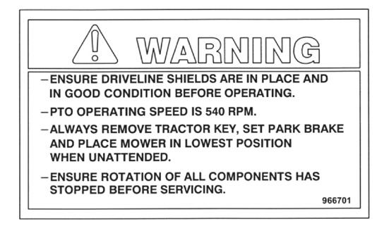
11 Safety - Finishing Mower 430, 530 & 630 Decal List Item Part Number Description Qty Decal - Reference Plate JBI/FK Serial # Decal - Warning Check PTO Shaft Decal - Fk 1.85 x 12 (4' & 5') Decal - Fk 2.88 x (6') Decal - 630, Fm Decal - 530, Fm Decal - 430, Fm Decal - Caution, No Riders Decal - Warning Safety Sign Decal - Warning, Fm Decal - Caution, Fm Decal - Danger, Fm Decal - Check Oil 1 11
12 Assembly - Finishing Mower 430, 530 & 630 Start-up 1. Park the unit on hard level ground with the mower slightly raised. 2. Adjust the sway blocks or chains on the tractor so the mower is centered between the rear wheels. 3. Adjust the 3-point hitch arms to level the mower side to side. 4. Adjust the turnbuckle on the top of the 3-point hitch arms to level the mower front and back. 5. Adjust the cutting height using the wheel spacers on the wheel yokes. The spacers should be set at the same height on all four wheels. 6. Check the oil level in the gearbox and add as required (see maintenance section). 7. Grease spindle assembly, wheel bearings, wheel pivots and the PTO shaft (see maintenance section). 8. Maintain proper air pressure in tires of 30 psi max. 9. Check tightness of belts, bolts and other hardware (see maintenance section). 10. Check blades to see if they are damaged. Sharpen or replace blades if necessary. Check that blade bolts are tight. 11. Clear the working area of foreign objects and check that all bystanders are standing clear before starting. 12. Start the tractor with the mower resting on the ground on all four wheels. 13. Slowly engage the PTO and bring the PTO speed up to 540 rpm for cutting. 12
13 Parts - Finishing Mower 430, 530 & 630 Operation Instructions The heavy-duty finishing mower is designed to be used on a tractor with a standard category 1 3-point hitch. See the specification sheet for horsepower requirements. Using excessive power will shorten the life of the drive train components. Connecting to Tractor Park the mower and tractor on a level dry area free of debris and foreign objects. 1. Slowly back the tractor up to the machine. 2. Adjust the 3-point arms to align with the mower lift pins. 3. Stop the tractor, set the parking brake and remove the ignition key before dismounting. 4. Slide the 3-point arms on the lift pins and lock in place with the clips supplied. 5. With the engine on the tractor shut off, attach the PTO shaft. Both ends of the PTO have a standard 6-spline end with a spring-loaded locking collar. Turn the round collar at the ends of the PTO clockwise to slide onto the splined shafts. The spring-loaded pin in the PTO yoke must lock into the groove on the splined shaft on the gearbox and tractor. Always check to see that both ends of the PTO shaft are securely attached every time the mower is used. This should always be done with the tractor engine shut off. Attach the safety chains supplied with the PTO shaft, allowing sufficient slack for the driveline during turns and operation. Check booklet attached to the PTO for instructions. NOTE: At least one third of the telescoping length of the PTO should overlap when the mower is in operation. 6. Attach the top link on the tractor to the link pin assembled in the hitch plate. Adjust the turnbuckle on the tractor top link so that the hitch sits straight with the tractor and mower both on level ground. 13
14 Operation - Finishing Mower 430, 530 & 630 Field Operation 1. The mower works best on dry grass. Slower cutting speed and occasional cleaning may be required on damp or wet grass. 2. The PTO must run at the full 540 rpm for a good cut. Slower speeds or double cutting could be required for very tall grass. 3. Use a higher blade setting for rough areas to prevent scalping of the surface. 4. Always cut counter-clockwise so grass clippings are thrown on the grass already cut. This saves power and wear on the blades. 5. Sharpen blades if grass tears instead of cutting cleanly. 6. Slow down when cutting corners. Turning too sharply on corners can leave a small strip of grass uncut. Disconnecting from Tractor 7. Park on a firm level area and clean the mower. 8. Lower the mower until the load is off the hitch arms. 9. Disconnect the hitch arms and the PTO shaft. 10. Cover the mower for storage to prevent rust. 14

15 Operation - Finishing Mower 430, 530 & 630 Theory of Operation 15
16 Operation - Finishing Mower 430, 530 & 630 Maintenance Mower Gearbox Lubrication The gearbox should be filled with SAE90 oil to the bottom of the level plug when shipped. Check the mower gearbox before using and at regular intervals (approximately every 40 hours). See that the oil level is maintained. On the mower gearbox the vent plug also acts as the fill plug. Mower Axle Lubrication Use a high temperature grease for all applications. There is a grease nipple in the sleeve welded to the ends of each of the four axles. These locations should receive 3 or 4 pumps of grease about every 8 hours. GREASE 16
17 Operation - Finishing Mower 430, 530 & 630 Blade Replacement The bolts have a patch of thread lock material pre-applied which will hold up for uses. Reapply thread lock if necessary. Blade Height Adjustment The mowers must be raised off the ground far enough to pull the wheel yoke out of the welded sleeves at the ends of the axles. Be sure the tractor is turned off. Pull out the clip and remove the wheel yoke. There are 1/2" (13 mm) and 1" (25 mm) spacers to adjust the cutting height. The cutting height is 1-1/2" (38 mm) with no spacers under the sleeve at the end of the axles. This can be adjusted using the spacers by 1/2" (13 mm) increments up to 5-1/2" (140 mm). Check to see that the spacers are set at the same height on all the wheel yokes. V-Belt Maintenance A few simple rules should be followed to satisfy most drive requirements: 1. For installation, reduce the center distance so the belt may be placed in the sheave grooves without force. Arrange the belt so that both the top and bottom spans have about the same amount of sag. Apply tension to the belt by adjusting tension on gearbox base plate until the belt is snug and has a live, springy action when struck with the hand. 2. Operate the drive a few minutes to seat the belt in the sheave grooves. Observe the operation of the drive under its highest load condition (usually starting). A slight bowing of the slack side of the drive indicates adequate tension. If the slack side remains taut during the peak load, the drive is too tight. 3. Check the tension on a new drive several times during the first 24 hours of operation, by observing the slack side span. 4. Keep the drive free of foreign material which might cause slippage or damage to the belt and sheave surfaces. 5. If a V-belt slips, it is too loose. Increase the tension by adjusting gearbox base plate. Never apply belt dressing, as this will damage the belt and cause early failure. 17
18 Maintenance - Finishing Mower 430, 530 & 630 Service Notes A basic requirement for a steady top performance of the machine is proper and regular maintenance. Use only original Farm King parts. Keep the machine in a functioning and efficient condition by completing the maintenance and lubrication work as listed in the maintenance checklist. If maintenance is due, no work is to be done with the machine. Discovered defects have to be carefully remedied at once. ATTENTION: The maintenance of the machine should be done by trained personnel. Naturally, the machine has to be secured prior to beginning any maintenance work. Intervals of Maintenance: The intervals are based on average working conditions and strain. The various intervals of maintenance depend on the time elapsed or service hours complete, which ever is reached first. The intervals given here are based on the quality of material specified in this manual. Every 8 Hours of Use Grease PTO cross journals and shield bearings. Grease mower deck wheel spindles. Grease mower spindles. Every 20 Hours of Use Grease PTO cardan tubes and release collars. Every 40 Hours of Use Check oil level of gearbox Yearly or Every 200 Hours of Use Repack mower bearings 18
19 Bolt Torque - Finishing Mower 430, 530 & 630 Bolt Torque Checking Bolt Torque The tables shown below give correct torque values for various bolts and hex bolts. Tighten all bolts to the torques specified in chart unless otherwise noted. Check tightness of bolts periodically, using bolt torque chart as a guide. Replace hardware with the same strength bolt. Bolt Torque* Bolt Diameter Grade 2 Bolts Grade 5 Bolts Grade 8 Bolts (inches) SAE 2 SAE 5 SAE 8 A (lb-ft) (N.m) (lb-ft) (N.m) (lb-ft) (N.m) 0.25 (1/4) (5/16) (3/8) (7/16) (1/2) (9/16) (5/8) (3/4) (7/8) NOTE: See page 15 for correct spindle torque. Do not use this chart for spindle bolt only. Torque figures indicated above are valid for non-greased or non-oiled threads and heads unless otherwise specified. Therefore, do not grease or oil bolts or hex bolts unless otherwise specified in this manual. When using locking elements, increase torque values by 5%. * Torque value for bolts and hex bolts are identified by their head markings. 19
20 Parts - Finishing Mower 430, 530 & 630 Axle Drawing 9 2 PLCS 3 2 PLCS PLCS NOTES: 1. ADJUST WHEEL HEIGHT WITH SPACER, ENSURE EQUAL SPACER HEIGHT IS USED ON ALL AXLES. 20
21 Parts - Finishing Mower 430, 530 & 630 When Ordering Parts Always give your dealer the Model, Color and Serial Number of your machine to assist him in ordering and obtaining the correct parts. Use the exploded view and tabular listing of the area of interest to exactly identify the required part. Item Part Number Description Qty /4" Lock Nut (Pl) /2 x 3" Carriage Bolt Gr5 (Pl) /2" Hex Nut Gr5 (Pl) /2" Lock Washer (Pl) Weldment Axle Std Wheel Yoke Weldt /16" Linch Pin (Pl) Wheel Height Spacers Ø 1-5/16" Od x 1" Wheel Height Spacer Ø 1-5/16" Od x 1/2" x Tire w/ Wheel Drive-In Grease Zerk /4" x 6" Carriage Bolt (Pl) 1 21
22 Parts - Finishing Mower 430, 530 & 630 Deck Drawing 2 PLCS 4 PLCS PLCS 4 PLCS PLCS PLCS PLCS PLCS 2 PLCS PLCS FOR DETAILS VIEW HITCH DRAWING PLCS FOR DETAILS VIEW AXLE DRAWING FOR DETAILS VIEW FRONT ROLLER DRAWING FOR DETAILS VIEW SPINDLE DRAWING 22
23 Parts - Finishing Mower 430, 530 & 630 Item Part Number Description Qty /16" x 2" Cotter Pin (Br) /16" Flat Washer (Pl) /16" Lock Washer (Pl) /8" Hex Nut (Pl) /8" Lock Washer (Pl) /8" Hex Nut (Pl) /8" Lock Washer (Pl) /8" Flat Washer (Pl) /8" x 1-3/4" Hex Bolt (Pl) /8" x 1" Hex Bolt Gr5 (Pl) /8 x 1-1/4 Carriage Bolt (Pl) Side PTO Guard /4" x 1/4" x 1-5/8" Key /4" x 1/4" x 1-7/64" Key V-Belt - B61 (4') Belt B-70 (5') " Slot Hex Nut Weldt Incl. w/ Gbox Sheave - Single 3-3/4" (4') Sheave - Double 3-3/4" (4') Sheave - Single 4-1/2" (5' & 6') Double Sheave Ø4-1/2" x 2.3" (5' & 6') Double Sheave 12" Gearbox (Without Oil) Snap Ring Deck Weldt 5' Std Deck Weldt 6' Std Weldment - Mount Gearbox Fm Std (5' & 6') Guard - Drivetrain Mower - 6' Right Guard - Drivetrain Mower - 6' Left Pulley Spacer Guard - Drivetrain Mower - 5' Right Guard - Drivetrain Mower - 5' Left Weldment - Deck 4' Std Plate - Shield Left 4' Std Plate - Shield Right 4' Std Weldment - Mount Gearbox 4' Fm Std " x 7/16" x 10Ga Flat Washer (Pl) V-Belt - B-78 (6') 2 23
24 Parts - Finishing Mower 430, 530 & 630 Item Part Number Description Qty Gearbox Base Weldt (Pl) /16" x 3/4" Sq Hd Set Screw (Br) 8 41 BU Hex Bolt 5/16 x 5/8" (Pl) 4 42 F0399 PTO Shaft 4' & 5' Fm 1 43 F0400 PTO Shaft 6' Fm 1 24
25 Parts - Finishing Mower 430, 530 & 630 Belt Drawing VIEW WITHOUT GEARBOX, GUARDS, HITCH, & AXLES ADJUST BELT TENSION BY MOVEMENT OF GEARBOX BASE PLATE ( ) VIEW WITHOUT GUARDS, HITCH, & AXLES NOTE: 1. TENSION BELTS ACCORDING TO MAINTENANCE GUIDELINES. 25
26 Parts - Finishing Mower 430, 530 & 630 Front Roller Drawing 2 PLCS PLCS 9 26
27 Parts - Finishing Mower 430, 530 & 630 Item Part Number Description Qty /4" x 3/4" Hex Bolt Gr5 (Pl) /4" Hex Nut (Pl) /4" Lock Washer (Pl) /8" Hex Nut (Pl) /8" Lock Washer (Pl) /16" Flat Washer (Pl) /8" x 1" Hex Bolt Gr5 (Pl) End Cap Front Roller Roller Tube Roller Pin Weldment Plate - Roller Holder Light Duty /4" x 2-1/2" Cotter Pin (Pl) 1 27
28 Parts - Finishing Mower 430, 530 & 630 Spindle Drawing Ø KEYWAY 2.16 EFF. KEYWAY /8-11 UNC - 2B 1.00 (CLASS H2) 2.50 TYP (5.00) (1.77) (3.54) 2 4 PLCS ATTACH ITEM WITH CUTTING EDGE DOWN AND FLANGE FACING UPWARDS PLCS 1 4 PLCS APPLY LOCTITE & TORQUE TO 180 FT-IBS 28
29 Parts - Finishing Mower 430, 530 & 630 Item Part Number Description Qty /8" x 1-1/2" Hex Bolt Gr5 (Pl) /8" Hex Nut (Pl) /8" Lock Washer (Pl) Hard Surfaced Blade 1/4" x 2-1/2" x 17-3/4" (4') Spindle Assembly (w/o Hardware) Spindle Assembly (w/ Hardware) /2" Od x 21/32" ID Washer (Pl) /8" x 1" Gr8 Hex Bolt Lock (Pl) /8" Lock Washer Extra Heavy (Pl) Hard Surfaced Blade 1/4" x 2-1/2" x 21-3/4" (5') Hard Surfaced Blade 1/4" x 2-1/2" x 25-3/4" (6') Standard Blade 1/4" x 2-1/2" x 21-3/4" (5') Standard Blade 1/4" x 2-1/2" x 17-3/4" (4') Standard Blade 1/4" x 2-1/2" x 25-3/4" (6') 1 29
30 Parts - Finishing Mower 430, 530 & 630 Hitch Drawing LOWER HOLE FOR USE WITH QUICK HITCH CLASS 1, IF NOT IN USE, FLIP BRACKET UP PART OF MAIN DECK PART OF MAIN DECK
31 Parts - Finishing Mower 430, 530 & 630 Item Part Number Description Qty /4" Lock Nut (Pl) /8" Lock Nut (Pl) /8" SAE Flat Washer (Pl) /16" x 1-1/4" Hex Bolt (Pl) /16" Hex Nut (Pl) /16" Lock Washer (Pl) /8" Hex Nut (Pl) /8" Lock Washer (Pl) /8" x 5" Hex Bolt Gr5 (Pl) /4" x 6" Hex Bolt Gr5 (Pl) /8" x 2" Hex Bolt Gr5 (Pl) /8 x 1-1/4 Carriage Bolt (Pl) Manual Holder 3-1/2" x 12" L Lower Hitch Plate Hitch Spacer Tube Plate - Rear Brace Left 5' Std Plate - Rear Brace Right 5' Std Plate - Rear Brace Left 6' Std Plate - Rear Brace Right 6' Std Plate - A Frame Left Light Duty Plate - A Frame Right Light Duty Brkt - PTO Holder Plate - Rear Brace Right 4' Std Plate - Rear Brace Left 4' Std Weldment - Upper Hitch Cat. 1 Top Link Pin /16" Linch Pin Lift Pin Bushing Lift Pin c/w Nut & Washer (Xl) (Cat.1) /8 x 2-1/4" Hex Bolt Gr5 (Pl) 4 31
32 Parts - Finishing Mower 430, 530 & 630 Chain Kit Drawing PLCS-4' & 5', 5 PLCS-6' 4 PLCS-4' & 5', 5 PLCS-6' 2 PLCS 2 PLCS 50 PLCS-4', 62 PLCS-5', 74 PLCS-6' PLCS-4' & 5', 5 PLCS-6' 4 PLCS-4' & 5', 5 PLCS-6' NOTE: 1. REAR AXLES, WHEEL NUTS AND BOLTS NOT SHOWN. 32
33 Parts - Finishing Mower 430, 530 & 630 Item Part Number Description Qty /8" x 1-1/2" Hex Bolt Gr5 (Pl) /8" Hex Nut (Pl) /8" Lock Washer (Pl) /8" Flat Washer (Pl) Chain Guard (Pl) 3-1/2" x 62" (5') Chain Guard Spacer Ø 5/8" Od x 5/8" Chain Guard (Pl) 3-1/2" x 74" (6') Chain Kit Rod Ø 3/8" x 62-3/8" (5') Chain Kit Rod Ø 3/8" x 74-3/8" (6') Chain Guard (Pl) 3-1/2" x 50" (4') Chain Kit Rod Ø 3/8" x 50-3/8" (4') Chain, 3 Link Rd /8" x 1" Cotter Pin (Pl) 2 33
34 Parts - Finishing Mower 430, 530 & 630 PTO Drawing COMPRESSED MAX OPERATION F0398 DATA - 1 3/8-6 SPLINE AS PER ASAE COMPRESSED MAX OPERATION F0399 DATA - 1 3/8-6 SPLINE AS PER ASAE Item Part Number Description Qty 1 F0398 PTO Shaft (4') 1 2 F0399 PTO Shaft (5' & 6') 1 34
35 Parts - Finishing Mower 430, 530 & 630 Gearbox Drawing 1 Ø1 3/8-6 SPLINE PRESSURE RELIEF VALVE & FILL PLUG LEVEL PLUG Item Part Number Description Qty Gearbox (w/o Oil) 1 35
36 Shipping Kit and Bundle Numbers - Finishing Mower 430, 530 & 630 Shipping Kit and Bundle Numbers The following is a list of Kit Numbers for this product and the Bundle Numbers, Descriptions, and Quantities for each Kit. Quantity Bundle Number Description 6' (72") Standard Finishing Mower (Y630) 1 F1436 Deck Assembly 6' (FM) 1 F6568 Carton w/ 4 Tires 5' (60") Standard Finishing Mower (Y530) 1 F1435 Deck Assembly 5' (FM) 1 F6568 Carton w/ 4 Tires 4' (48") Standard Finishing Mower (Y430) 1 F1438 Deck Assembly 4' (FM) 1 F6568 Carton w/ 4 Tires The following is a list of Kit Numbers for this product and the Bundle Numbers, Descriptions, and Quantities for each Kit. Quantity Bundle Number Description 1 Y610 Chain Kit (Consists of F6671 & F6674) 1 Y510 Chain Kit (Consists of F6670 & F6673) 1 Y410 Chain Kit (Consists of F0040 & F0041) 36
37 Shipping Kit and Bundle Numbers - Finishing Mower 430, 530 & 630 Suggested Service Parts Stock The following is a list of suggested service parts stock quantities. Part Number / Description Qty. Per Unit Qty. Per 10 Units PTO Shafts F0398-4' 1 1 F0399-5' & 6' 1 1 Gear Boxes Belts V-Belt B-61-4' B-70-5' V-Belt B-78-6' 2 6 Blades Reg Hard Surf Reg Hard Surf Reg Hard Surf Spindles ', 5' & 6' 3 3 Wheel ', 5' & 6' 4 2 Wheel Yoke ', 5' & 6' ', 5' & 6' 4 2 Wheel Spacers /16" od x 1" /16" od x 1/2" 8 16 Sheave (Pully) (906551) - 3-3/4" single - 4' (906552) - 3-3/4" double - 4' (906553) - 4-1/2" single - 5' & 6' (906554) - 4-1/2" double - 5' & 6'
38 Warranty - Finishing Mower 430, 530 & 630 Farm King Limited Warranty This document limits your warranty rights. Base Limited Warranty Buhler Industries Inc. provides this warranty only to original retail purchasers of its product. Buhler Industries Inc. warrants to such purchasers that all Buhler Industries Inc. manufactured parts and components used and serviced as provided for in the Operator s Manual shall be free from defects in materials and workmanship for a period following delivery to the original retail purchaser of 12 months (80 days for commercial applications). This limited warranty applies only to those parts and components manufactured by Buhler Industries Inc. Parts and components manufactured by others are subject to their manufacturer s warranties, if any. Buhler Industries Inc. will fulfill this limited warranty by, at its option, repairing or replacing any covered part that is defective or is the result of improper workmanship, provided that the part is returned to Buhler Industries Inc. within thirty (30) days of the date that such defect or improper workmanship is, or should have been, discovered. Buhler Industries Inc. reserves the right to either inspect the product at the buyer s location or have it returned to the factory for inspection. Parts must be returned through the selling representative and the buyer must prepay transportation charges. Buhler Industries Inc. will not be responsible for repairs or replacements that are necessitated, in whole or part, by the use of parts not manufactured by or obtained from Buhler Industries Inc. Under no circumstances are component parts warranted against normal wear and tear. There is no warranty on product pump seals, product pump bearings, rubber product hoses, pressure gauges, or other components that require replacement as part of normal maintenance. Also: Buckets and Bucket Tines carry no warranty, Bent Spears carry no warranty, Snowblower Fan Shafts carry no warranty, Mower Blades carry no warranty, Portable Auger Parts Have Two (2) Year Warranty, Loader Parts Have Two (2) Year Warranty. The purchaser is solely responsible for determining suitability of goods sold. This warranty is expressly in lieu of all other warranties expressed or implied. Buhler Industries Inc. will in no event be liable for any incidental or consequential damages whatsoever. Nor for any sum in excess of the price received for the goods for which liability is claimed. Repair Parts Limited Warranty Buhler Industries Inc. warrants Farm King replacement parts purchased after the expiration of the Buhler Industries Inc. Limited Warranty, and used and serviced as provided for in the Operator s Manual, to be free from defects in materials or workmanship for a period of thirty (30) days from the invoice date for the parts. Buhler Industries Inc. will fulfill this limited warranty by, at its option, repairing or replacing any covered part that is defective or is the result of improper workmanship, provided that the part is returned to Buhler Industries Inc. within thirty (30) days of the date that such defect or improper workmanship is, or should have been, discovered. Such parts must be shipped to Buhler Industries Inc. at the purchaser s expense. What is Not Covered Under no circumstances does this limited warranty cover any components or parts that have been subject to the following: negligence; alteration or modification not approved by Buhler Industries Inc.; misuse; improper storage; lack of reasonable and proper maintenance, service, or repair; normal wear; damage from failure to follow operating instructions; accident; and/ or repairs that have been made with parts other than those manufactured, supplied, and or authorized by Buhler Industries Inc. 38
39 Warranty - Finishing Mower 430, 530 & 630 Authorized Dealer and Labor Costs Repairs eligible for labor under this limited warranty must be made by Buhler Industries Inc. or an authorized Farm King dealer. Buhler Industries Inc. retains the exclusive discretion to determine whether it will pay labor costs for warranty repairs or replacements, and the amount of such costs that it will pay and the time in which the repairs will be made. If Buhler Industries Inc. determines that it will pay labor costs for warranty work, it will do so by issuing a credit to the dealer s or distributor s account. Buhler Industries Inc. will not approve or pay invoices sent for repairs that Buhler Industries Inc. has not previously approved. Warranty service does not extend the original term of this limited warranty. Warranty Requirements To be covered by warranty, each Farm King new product must be registered with Buhler Industries Inc. within thirty (30) days of delivery to original retail purchaser. If the customer decides to purchase replacement components before the warranty disposition of such components is determined, Buhler Industries Inc. will bill the customer for such components and then credit the replacement invoice for those components later determined to be covered by this limited warranty. Any such replacement components that are determined not be covered by this limited warranty will be subject to the terms of the invoice and shall be paid for by the purchaser. Warranty Claims: Warranty requests must be prepared on Buhler Industries Inc. Warranty Claim Forms with all requested information properly completed. Warranty Claims must be submitted within a thirty (30) day period from date of failure repair. Warranty Labor: Any labor subject to warranty must be authorized by Buhler Industries Inc. The labor rate for replacing defective parts, where applicable, will be credited at 100% of the dealer s posted shop rate. Exclusive Effect of Warranty and Limitation of Liability TO THE EXTENT PERMITTED BY LAW, BUHLER INDUSTRIES INC. DISCLAIMS ANY WARRANTIES, REPRESENTATIONS, OR PROMISES, EXPRESS OR IMPLIED, AS TO THE QUALITY, PERFORMANCE, OR FREEDOM FROM DEFECT OF THE COMPONENTS AND PARTS COVERED BY THIS WARRANTY AND NOT SPECIFICALLY PROVIDED FOR HEREIN. TO THE EXTENT PERMITTED BY LAW, BUHLER INDUSTRIES INC. DISCLAIMS ANY IMPLIED WARRANTIES OF MERCHANTABILITY AND FITNESS FOR A PARTICULAR PURPOSE ON ITS PRODUCTS COVERED HEREIN, AND DISCLAIMS ANY RELIANCE BY THE PURCHASER ON BUHLER INDUSTRIES INC. S SKILL OR JUDGMENT TO SELECT OR FURNISH GOODS FOR ANY PARTICULAR PURPOSE. THE PURCHASER S ONLY AND EXCLUSIVE REMEDIES IN CONNECTION WITH THE BREACH OR PERFORMANCE OF ANY WARRANTY ON PRODUCTS MANUFACTURED BY BUHLER INDUSTRIES INC. ARE THOSE SET FORTH HEREIN. IN NO EVENT SHALL BUHLER INDUSTRIES INC. BE LIABLE FOR INCIDENTAL OR CONSEQUENTIAL DAMAGES (INCLUDING, BY WAY OF EXAMPLE ONLY AND NOT LIMITATION, LOSS OF CROPS, LOSS OF PROFITS OR REVENUE, OTHER COMMERCIAL LOSSES, INCONVENIENCE, OR COST OF REPLACEMENT OF RENTAL EQUIPMENT). IN NO EVENT SHALL FARM KING S CONTRACT OR WARRANTY LIABILITY EXCEED THE PURCHASE PRICE OF THE PRODUCT. 39
40 Warranty - Finishing Mower 430, 530 & 630 (Note that some provinces or states do not allow limitations on how long an implied warranty lasts or the exclusion or limitation of incidental or consequential damages, so the above limitations and exclusion may not apply to you.) This warranty gives you specific legal rights and you may also have other rights, which vary from province to province or state to state. Buhler Industries Inc. neither assumes nor authorizes any person or entity, including its selling representatives, to assume any other obligations or liability in connections with the sale of covered equipment, or to make any other warranties, representations, or promises, express or implied, as to the quality, performance, or freedom from defect of the components and parts covered herein. No one is authorized to alter, modify, or enlarge this limited warranty, or its exclusions, limitations and reservations. Corrections of defects and improper workmanship in the manner, and for the applicable time periods, provided for herein shall constitute fulfillment of all responsibilities of Buhler Industries Inc. to the purchaser, and Buhler Industries Inc. shall not be liable in negligence, contract, or on any other basis with respect to the subject equipment. This limited warranty is subject to any existing conditions of supply which may directly affect Buhler Industries Inc. s ability to obtain materials or manufacture replacement parts. Buhler Industries Inc. reserves the right to make improvements in design or changes in specifications to its products at anytime, without incurring any obligation to owners of units previously sold. Government Legislation: Warranty terms and conditions are subject to provincial or state legislation. Important Note: This warranty does not apply to rentals. 40
41
42 301 Mountain Street South Morden, Manitoba Canada R6M 1X7 Ph.: Fax: Toll Free: Equipment shown is subject to change without notice Buhler Trading Inc. Printed in USA. TSX:BUI a division of Buhler Industries Inc.
Operator and Parts Manual
 Operator and Parts Manual Utility Auger 6" Model 092010 FK339 Table of Contents - 6" Utility Auger Table of Contents Introduction...4 Safety...5 Safety...5 General Safety...6 Start-up Safety...6 Operation
Operator and Parts Manual
 Operator and Parts Manual Landscape Rake 60", 72", 84" & 90" Model 092010 FK349 Table of Contents - 60", 72", 84" & 90" Land Rake Table of Contents Introduction...4 Safety...5 Safety...6 General Safety...6
Operator and Parts Manual. Power Mover
 Operator and Parts Manual Power Mover 042010 26089 Table of Contents - Power Mover Table of Contents Introduction...4 Safety...5 Safety...5 General Safety...6 Start-up Safety...6 Operation Safety...6
OPERATOR AND PARTS MANUAL
 OPERATOR AND PARTS MANUAL Finishing Mower Model 555, 655 & 755 082012 FK391 Table of Contents - 555, 655 & 755 Finishing Mower Table of Contents Introduction...5 Safety...6 Safety Instruction...6 General
Operator and Parts Manual. Hammermill FK354
 Operator and Parts Manual Hammermill 092014 FK354 Table of Contents - Hammermill Table of Contents Introduction...4 Safety...5 Safety...5 Assembly...6 Assembly Instructions...6 Operation...7 Operation
Operator and Parts Manual. Finishing Mower FK301
 Operator and Parts Manual Finishing Mower 072011 FK301 Table of Contents - Finishing Mower Table of Contents Introduction...5 Safety...6 Safety Instruction...6 General Safety...7 Start-up Safety...7 Operation
Operator and Parts Manual
 Operator and Parts Manual Rollermill Model 85 & 100 122010 FK317 Table of Contents - Rollermill 85 & 100 Table of Contents Introduction...4 Safety...5 Safety...5 General Safety...6 Start-up Safety...6
WARRANTY REGISTRATION AND POLICY
 WARRANTY REGISTRATION AND POLICY Buhler Manufacturing products are warranted for a period of twelve (12) months from original date of purchase, by original purchaser, to be free from defects in material
Finishing Mower TABLE OF CONTENTS
 TABLE OF CONTENTS DESCRIPTION PAGE NUMBER Warranty 1 Operating Safety 2 Transport Safety 3 Maintenance Safety 3 Safety Signs 4 Hitch Assembly Instructions 5 Operating Instructions 6 Field Use Preparation
OPERATOR AND PARTS MANUAL
 OPERATOR AND PARTS MANUAL Snowblower Models 500, 600 & 660 082013 FK311 Table of Contents - 500, 600 & 660 Snowblower Table of Contents Introduction...4 Safety...5 Safety...5 General Safety...6 Start-up
Two-Stage Snow Blower For 4WD Pick Up Trucks. Operator s Manual
 Two-Stage Snow Blower For 4WD Pick Up Trucks Operator s Manual Distrubuted by: Metal Fabricating LLC P.O. Box 831 Brodheadsville, PA 18322 Phone: 570-992-9989 SnowVac.com WARRANTY POLICY Metal Fabricating
OPERATOR AND PARTS MANUAL
 OPERATOR AND PARTS MANUAL Snowblower Models 5010, 6010 & 6610 032014 FK312 Table of Contents - 5010, 6010 & 6610 Snowblower Table of Contents Introduction...4 Safety...5 Safety...5 General Safety...6
TABLE OF CONTENTS DESCRIPTION. Safety Instructions & Safety Sign Locations Operating Instructions Assembly Instructions...
 TABLE OF CONTENTS DESCRIPTION PAGE Warranty... 1 Safety Instructions & Safety Sign Locations... 2 Operating Instructions... 3 Assembly Instructions... 5 500 & 600 Snowblower Drawings... 8 500 & 600 Snowblower
WARRANTY REGISTRATION AND POLICY
 WARRANTY REGISTRATION AND POLICY Buhler Manufacturing products are warranted for a period of twelve (12) months from original date of purchase, by original purchaser, to be free from defects in material
TABLE OF CONTENTS WARRANTY... 1 INTRODUCTION... 2
 TABLE OF CONTENTS DESCRIPTION PAGE WARRANTY... 1 INTRODUCTION... 2 SAFETY... 3 Safety... 3 General Safety... 4 Start-up Safety... 4 Operation Safety... 4 Transport Safety... 4 Service and Maintenance Safety...
TABLE OF CONTENTS DESCRIPTION WARRANTY... 1 INTRODUCTION... 2
 TABLE OF CONTENTS DESCRIPTION PAGE WARRANTY... 1 INTRODUCTION... 2 SAFETY... 3 Safety... 3 General Safety... 4 Start-up Safety... 4 Operation Safety... 4 Transport Safety... 4 Service and Maintenance Safety...
WARRANTY REGISTRATION AND POLICY
 WARRANTY REGISTRATION AND POLICY Buhler Manufacturing products are warranted for a period of twelve (12) months from original date of purchase, by original purchaser, to be free from defects in material
TABLE OF CONTENTS DESCRIPTION PAGE WARRANTY...1 INTRODUCTION...2
 Triplex Finishing Mower TABLE OF CONTENTS DESCRIPTION PAGE WARRANTY...1 INTRODUCTION...2 SAFETY...3 Safety...3 General Safety...4 Start Up Safety...4 Operation Safety...4 Transport Safety...5 Service and
OPERATOR AND PARTS MANUAL. Drive Over Hopper SZ000402
 OPERATOR AND PARTS MANUAL Drive Over Hopper 042011 SZ000402 Table of Contents - Drive Over Hopper Table of Contents Introduction...4 Safety...5 Safety...5 Operator Qualifications...7 Assembly...8 Hanger
Operator and Parts Manual
 Operator and Parts Manual 960 Snowblower 5/2010 FK315 Table of Contents - 960 Snowblower Table of Contents Warranty Policy 4 Introduction 5 Safety 6 Safety 6 General Safety 7 Start up Safety 7 Operation
RED23305 Owner s Manual
 RED23305 Owner s Manual 5 foot, 3-Point Mounted Snow Blower 270 West Park Avenue Huron, SD 57350 866-526-5682 Serial Number: Date of Purchase: Red Devil Snow Blower See Figure 1. 1. The Red Devil Snow
Operator and Parts Manual
 Operator and Parts Manual Conventional Auger Model 1266, 1272 & 1282 092010 SZ000189 Table of Contents - 1266, 1272 & 1282 Conventional Auger Table of Contents Introduction...4 Safety...5 Safety...5 General
WARRANTY REGISTRATION AND POLICY
 WARRANTY REGISTRATION AND POLICY Buhler Manufacturing products are warranted for a period of twelve (12) months from original date of purchase, by original purchaser, to be free from defects in material
Operator and Parts Manual
 Operator and Parts Manual Conventional Auger Model 1034 092010 SZ000251 Table of Contents - 1034 Conventional Auger Table of Contents Introduction...4 Safety...5 Safety...5 General Safety...5 Operation
Operator and Parts Manual
 Operator and Parts Manual Rotary Tiller 65 Series - 50", 60", 72" & 82" 082010 FK302 Table of Contents - 65 Series Rotary Tiller Table of Contents Introduction...5 Safety...6 Safety...6 General Safety...7
Model 35 PARTS MANUAL
 Model 35 PARTS MANUAL Version 3-2007 Ashland Industries Inc. 1115 Rail Drive P.O. Box 717 Ashland, WI. 54806 Ph: 877-634-4622 Toll Free Ph: 715-682-4622 Fx: 715-682-9717 www.ashlandind.com Model 35 Scraper
MK AUGERS POWER SWING KIT ASSEMBLY & OPERATION MANUAL
 MK AUGERS POWER SWING KIT ASSEMBLY & OPERATION MANUAL Read this manual before using product. Failure to follow instructions and safety precautions can result in serious injury, death, or property damage.
OPERATOR AND PARTS MANUAL
 OPERATOR AND PARTS MANUAL Snowblower Model 960 042014 FK315 Table of Contents - 960 Snowblower Table of Contents Introduction...4 Safety...5 Safety...5 General Safety...6 Start-up Safety...6 Operation
Operator and Parts Manual. 834 Conventional Auger SZ000254
 Operator and Parts Manual 834 Conventional Auger 082010 SZ000254 Introduction - 834 Conventional Auger 834 Conventional Auger TO THE OWNER Thank you for purchasing a Farm King 834 Conventional Auger. Farm
ASSEMBLY INSTRUCTION MANUAL
 ASSEMBLY INSTRUCTION MANUAL 10" & 13" Backsaver Augers Electric Mover Kit 022014 SZ001099 Table of Contents - 10" and 13" Backsaver Augers - Electric Mover Kit Table of Contents Introduction...4 Safety...5
OPERATOR S MANUAL FABRIC 3-BAG GRASS CATCHER PART NO PRINTED 8/2012 PRINTED IN USA
 OPERATOR S MANUAL FABRIC -BAG GRASS CATCHER Models: GC-STC-V This manual contains the operating instructions and safety information for your Scag mower accessory. Reading this manual can provide you with
TABLE OF CONTENTS. Winch (No. 1550) Drawing Winch (No. 1550) Parts List Winch (No. K2550) Drawing Winch (No. K2550) Parts List...
 Drawing Winch (No. 1550) Parts List Winch (No. K2550) Drawing Winch (No. K2550) Parts List...") TABLE OF CONTENTS DESCRIPTION PAGE NUMBER Warranty... 1 Safety Instructions... 2 Safety Signs... 4 Operating Instructions... 6 Maintenance and Lubrication... 8 Storage... 8 Assembly Instructions... 9 Tube
TABLE OF CONTENTS DESCRIPTION PAGE NUMBER Warranty... 1 Safety Instructions... 2 Safety Signs... 4 Operating Instructions... 6 Maintenance and Lubrication... 8 Storage... 8 Assembly Instructions... 9 Tube
p.t.o. Slip clutch Read this material before using this product. Failure to do so can result in serious injury. Save this manual.
 p.t.o. Slip clutch 65517 Installation Instructions Distributed exclusively by Harbor Freight Tools. 3491 Mission Oaks Blvd., Camarillo, CA 93011 Visit our website at: http://www.harborfreight.com Read
Operator s Manual and Assembly
 Operator s Manual and Assembly Published: Mar 24, 2017 Manual Part No. AH02-00-MAN Gatco Manufacturing Inc. www.gatcomfg.com Location: 2524 South Service Road West, Swift Current, SK, Canada Mail: Box
MT2000 HYDRAULIC SWATH ROLLER COMMON HYDRAULIC ASSEMBLY INSTRUCTIONS Kit Part No
 Free Form PLASTICS MT2000 HYDRAULIC SWATH ROLLER COMMON HYDRAULIC ASSEMBLY INSTRUCTIONS Kit Part No. 7101-02 ASSEMBLY INSTRUCTIONS & OPERATION EFFECTIVE S/N: 39632SR01 - DATE It is recommended to carefully
OWNER S MANUAL 40 LAWN AERATOR SAT-40 BH. Assembly Installation Operation Repair Parts. Visit us on the web! MODEL:
 OWNER S MANUAL 40 LAWN AERATOR MODEL: SAT-40 BH Assembly Installation Operation Repair Parts For the latest product updates & setup tips: Visit us on the web! www.brinly.com Important: This manual contains
TABLE OF CONTENTS. Warranty Disclaimers Delivery Checklist After Sale Checklist Safety Set Up... 8
 TABLE OF CONTENTS Pickett Equipment Warranty... 2 Warranty Disclaimers... 3 Delivery Checklist... 4 After Sale Checklist... 4 Safety... 5-7 Set Up... 8 Machine Adjustments and Operation... 9 Maintenance
Operator and Parts Manual
 Operator and Parts Manual Conventional Auger Model 1066 & 1076 112010 SZ000252 Table of Contents - 1066 & 1076 Conventional Auger Table of Contents Introduction...4 Safety...5 Safety...5 General Safety...5
Angle Grinder Holder
 Angle Grinder Holder Owner s Manual WARNING: Read carefully and understand all ASSEMBLY AND OPERATION INSTRUCTIONS before operating. Failure to follow the safety rules and other basic safety precautions
GRADING SCRAPERS INDUSTRIAL SERIES OPERATION, SERVICE & PARTS MANUAL FOR MODELS: GSI7-SS, GSI7, GSI8, GSI10, & GSI12.
 GRADING SCRAPERS INDUSTRIAL SERIES OPERATION, SERVICE & PARTS MANUAL FOR MODELS: GSI7-SS, GSI7, GSI8, GSI10, & GSI12 September 2006 FORM: IndGradingScrpr.QXD TABLE OF CONTENTS Safety Information......................1-2
OPERATOR S MANUAL MODEL RS-2
 MODEL RS-2 SC500G2A THIS MANUAL CONTAINS THE OPERATING INSTRUCTIONS AND SAFETY INFORMATION FOR YOUR SCAG ACCESSORY. READING THIS MANUAL CAN PROVIDE YOU WITH AS- SISTANCE IN MAINTENANCE AND ADJUST- MENT
3-Pt. Quick Hitch. Owner s Manual
 3-Pt. Quick Hitch Owner s Manual WARNING: Read carefully and understand all ASSEMBLY AND OPERATION INSTRUCTIONS before operating. Failure to follow the safety rules and other basic safety precautions may
ENGINE DRIVEN ROTARY MOWER
 ENGINE DRIVEN ROTARY MOWER Operation, Service & Parts Manual For Models ERM-413, 416, & 617 April 2009 Form: ERMHydMower TABLE OF CONTENTS SECTION DESCRIPTION...PAGE 1 Introduction... 1 2 Preparation...2
ROTARY MOWER OPERATION, SERVICE & PARTS MANUAL FOR
 ROTARY MOWER OPERATION, SERVICE & PARTS MANUAL FOR L-G-40-40-P, L-G-48-40-P, L-G-60-40-P & L-G-72-40-P Slip Clutch Models: L-G-60-40-SC-P & L-G-72-40-SC-P February 2003 FORM: RotMwrBook.QXD TABLE OF CONTENTS
OPERATOR S MANUAL MODEL GC-SFZ
 R Made in the USA by MODEL GC-SFZ THIS MANUAL CONTAINS THE OPERATING INSTRUCTIONS AND SAFETY INFORMA- TION FOR YOUR SCAG ACCESSORY. READ- ING THIS MANUAL WILL PROVIDE YOU WITH MAINTENANCE AND ADJUSTMENT
60in. Acreage Rake. Owner s Manual
 60in. Acreage Rake Owner s Manual WARNING: Read carefully and understand all ASSEMBLY AND OPERATION INSTRUCTIONS before operating. Failure to follow the safety rules and other basic safety precautions
Push Trolley. Owner s Manual
 Push Trolley Owner s Manual WARNING: Read carefully and understand all ASSEMBLY AND OPERATION INSTRUCTIONS before operating. Failure to follow the safety rules and other basic safety precautions may result
TABLE OF CONTENTS DESCRIPTION WARRANTY... 1 INTRODUCTION... 2
 TABLE OF CONTENTS DESCRIPTION PAGE WARRANTY... 1 INTRODUCTION... 2 SAFETY... 3 Safety... 3 General Safety... 4 Start-up Safety... 4 Operation Safety... 4 Transport Safety... 4 Service and Maintenance Safety...
MAXILATOR OPERATOR'S MANUAL INLINE MOWER CADDY MODEL MBS RICE ROAD ROCKMART, GA (866) HAYBALE
 HAYBALE") MAXILATOR OPERATOR'S MANUAL INLINE MOWER CADDY MODEL MBS-80 51 RICE ROAD ROCKMART, GA 30153 (866) HAYBALE MAXILATOR EQUIPMENT, LLC Phone: (866) HAYBALE LIMITED WARRANTY Effective January 1, 2016 Maxilator
MAXILATOR OPERATOR'S MANUAL INLINE MOWER CADDY MODEL MBS-80 51 RICE ROAD ROCKMART, GA 30153 (866) HAYBALE MAXILATOR EQUIPMENT, LLC Phone: (866) HAYBALE LIMITED WARRANTY Effective January 1, 2016 Maxilator
TABLE OF CONTENTS DESCRIPTION. Warranty...1
 Rollermill TABLE OF CONTENTS DESCRIPTION PAGE Warranty...1 Assembly Instructions...2 Operating Instructions...3 Safety Instructions...4 Rollermill Drawings...5 Rollermill Parts List...7 PTO Shaft Drawing
Operation and Parts Manual
 Operation and Parts Manual 3-Point PTO and Hydraulic Stump Grinders Models: SC-25 and SC-25H SC-50 and SC-50H Safety Operation Maintenance Repair Troubleshooting Parts Parts SC-50 and SC-50-H Stumpbuster
TRUSS KITS FOR SPOUTING Installation Manual
 TRUSS KITS FOR SPOUTING Installation Manual LAMBTON CONVEYOR LIMITED 102 Arnold Street Wallaceburg, ON N8A 3P4 Canada Telephone: (519) 695-2316 Telephone: (519) 627-8228 ONE SOURCE ONE SOLUTION Toll free:
Heavy-Duty Drywall Dolly Cart
 Heavy-Duty Drywall Dolly Cart Owner s Manual WARNING: Read carefully and understand all ASSEMBLY AND OPERATION INSTRUCTIONS before operating. Failure to follow the safety rules and other basic safety precautions
Heavy-Duty Welding Fabrication Table
 Heavy-Duty Welding Fabrication Table with Fix-Up Kit Owner s Manual WARNING: Read carefully and understand all ASSEMBLY AND OPERATION INSTRUCTIONS before operating. Failure to follow the safety rules and
OPE R AT O R S MANU A L QUICK-HITCH ADAPTER. 5BP (Field conversion kit)
") OPE R AT O R S MANU A L 5BP006750 (Field conversion kit) Manual 5BP97378B Date 06/8/05 SAFETY Take note! This safety alert symbol found throughout this manual is used to call your attention to instructions
OPE R AT O R S MANU A L 5BP006750 (Field conversion kit) Manual 5BP97378B Date 06/8/05 SAFETY Take note! This safety alert symbol found throughout this manual is used to call your attention to instructions
OPERATOR S MANUAL. 20-bu 3-Point Hitch Material Collection System. LP65048 Supplier ST /07/2017 English. North American Edition Printed in USA
 OPERATOR S MANUAL 20-bu 3-Point Hitch Material Collection System LP65048 Supplier ST48289 11/07/2017 English North American Edition Printed in USA Introduction Using Your Operator s Manual Read this entire
ROTARY BRUSH CUTTERS THE LEADER OF THE PACK OWNER/OPERATOR SAFETY & INSTRUCTION MANUAL
 72 M-AX ROTARY BRUSH CUTTERS THE LEADER OF THE PACK OWNER/OPERATOR SAFETY & INSTRUCTION MANUAL CONTENTS Page 1. Introduction..................................2 2. Safety Instructions...........................3-4
Adjustable Steel Welding Table
 Adjustable Steel Welding Table Owner s Manual WARNING: Read carefully and understand all ASSEMBLY AND OPERATION INSTRUCTIONS before operating. Failure to follow the safety rules and other basic safety
TABLE OF CONTENTS DESCRIPTION. Warranty...1. Introduction...2
 TABLE OF CONTENTS DESCRIPTION PAGE Warranty...1 Introduction...2 Safety...3 General Safety...4 Operating Safety...4 Maintenance Safety...5 Transport Safety...5 Storage Safety...5 Safety Signs...5 Safety
MAXILATOR OPERATOR'S MANUAL INLINE MOWER CADDY MODEL MBS RICE ROAD ROCKMART, GA (866) HAYBALE
 HAYBALE") MAXILATOR OPERATOR'S MANUAL INLINE MOWER CADDY MODEL MBS-80 51 RICE ROAD ROCKMART, GA 30153 (866) HAYBALE MAXILATOR EQUIPMENT, LLC Phone: (866) HAYBALE LIMITED WARRANTY Effective January 1, 2016 Maxilator
MAXILATOR OPERATOR'S MANUAL INLINE MOWER CADDY MODEL MBS-80 51 RICE ROAD ROCKMART, GA 30153 (866) HAYBALE MAXILATOR EQUIPMENT, LLC Phone: (866) HAYBALE LIMITED WARRANTY Effective January 1, 2016 Maxilator
OPERATOR AND PARTS MANUAL. Grain Cleaner. Model FK327
 OPERATOR AND PARTS MANUAL Grain Cleaner Model 360 112017 FK327 360 Grain Cleaner Table Of Contents Manufacturer s Statement: For technical reasons, Buhler Industries Inc. reserves the right to modify
84in. Driveway Drag. Owner s Manual
 84in. Driveway Drag Owner s Manual WARNING: Read carefully and understand all ASSEMBLY AND OPERATION INSTRUCTIONS before operating. Failure to follow the safety rules and other basic safety precautions
Owner's Manual LAWN AERATOR MODELS: PA-40 BH PA-48 BH. Assembly Installation Operation Repair Parts
 Owner's Manual LAWN AERATOR MODELS: PA-40 BH PA-48 BH Assembly Installation Operation Repair Parts For use with Riders and Lawn/Garden Tractors IMPORTANT This manual contains information for the safety
AG PRODUCTS, LTD. YOU RE ALWAYS AHEAD... WITH A MODERN BEHIND.
 SUMMER 2016 BADGER DISC HARROW Operator s Manual 011-1156 011-1166 001-1501 001-1501-1 011-1167 001-1501-2 001-1501-3 011-1176 001-1501-4 011-1177 MODERN AG PRODUCTS, LTD. YOU RE ALWAYS AHEAD... WITH A
610 BUSHEL MANURE SPREADER
 610 BUSHEL MANURE SPREADER RODA MANUFACTURING 1008 LOCUST ST. HULL, IA. 51239 Art s-way Manufacturing 712-439-2366 Co., Inc. Hwy 9 West - PO Box 288 WWW.RODAMFG.COM Armstrong, IA. 50514 U.S.A 2 INTRODUCTION
Prime Attachments & Custom Fab Brush Mower Owners/Operators Manual
 Prime Attachments & Custom Fab Brush Mower Owners/Operators Manual The operator is responsible for the safe operation and maintenance of the machine. It is important that anyone who uses the machine is
OPERATOR S MANUAL MODEL GC-STC-V
 MODEL GC-STC-V THIS MANUAL CONTAINS THE OPERATING INSTRUCTIONS AND SAFETY INFORMA- TION FOR YOUR SCAG ACCESSORY. READ- ING THIS MANUAL WILL PROVIDE YOU WITH MAINTENANCE AND ADJUSTMENT PROCEDURES TO KEEP
Sawhorse with Chainsaw Holder
 Sawhorse with Chainsaw Holder Owner s Manual Chainsaw not included. WARNING: Read carefully and understand all ASSEMBLY AND OPERATION INSTRUCTIONS before operating. Failure to follow the safety rules and
TABLE OF CONTENTS DESCRIPTION WARRANTY... 1 INTRODUCTION ASSEMBLY... 9 Assembly Instructions... 9
 TABLE OF CONTENTS DESCRIPTION PAGE WARRANTY... 1 INTRODUCTION... 2 SAFETY... 3 Safety... 3 General Safety... 4 Start Up Safety... 4 Operation Safety... 4 Transport Safety... 5 Service and Maintenance Safety...
ROTARY TILLER. Operation, Service & Parts Manual For "AS" Series. FORM: ASTillerBook.QXD
 ROTARY TILLER Operation, Service & Parts Manual For "AS" Series FORM: ASTillerBook.QXD April 2002 TABLE OF CONTENTS Preparation......................................1 Assembly Instructions.............................2
OPERATORS MANUAL FOR KAFURTER ROTARY TOPPERS MODELS: TP110, TP140, TP160, TP170
 OPERATORS MANUAL FOR KAFURTER ROTARY TOPPERS MODELS: TP110, TP140, TP160, TP170 SAFETY WARNING: Do not use or operate this this manual and assembly instructions (where applicable) has been read and understood.
Hydraulic Bead Breaker Kit
 Hydraulic Bead Breaker Kit Owner s Manual WARNING: Read carefully and understand all ASSEMBLY AND OPERATION INSTRUCTIONS before operating. Failure to follow the safety rules and other basic safety precautions
OWNER'S MANUAL L A W N R O L L E R PRT-481S BH. Safety Assembly Operation Repair Parts Maintenance. Visit us on the web!
 OWNER'S MANUAL L A W N R O L L E R ROLLER MODEL: PRC- BH PRT- BH PRT-S BH PRT-S BH Safety Assembly Operation Repair Parts Maintenance Recommended for use with Riding Mowers, Lawn or Garden Tractors, and
11 ½" MODEL SINGLE CHAIN CONVEYOR
 11 ½" MODEL SINGLE CHAIN CONVEYOR USER S MANUAL 11 ½" Chain conveyor Revision 2011-05-31 2 CONTENTS WARRANTY...3 FOREWORD...4 SAFETY PRECAUTIONS...5 ASSEMBLY INSTRUCTIONS...6 SPECIFICATIONS...6 ASSEMBLING
MT2000 HYDRAULIC SWATH ROLLER MODEL - MACDON M150/M200 SERIES & JOHN DEERE W150
 MT2000 HYDRAULIC SWATH ROLLER MODEL - MACDON M150/M200 SERIES & JOHN DEERE W150 ASSEMBLY INSTRUCTIONS & OPERATION EFFECTIVE S/N: 39632SR01 - DATE View an installation on our Youtube Channel! It is recommended
Push Trolley. Owner s Manual
 Push Trolley Owner s Manual WARNING: Read carefully and understand all ASSEMBLY AND OPERATION INSTRUCTIONS before operating. Failure to follow the safety rules and other basic safety precautions may result
Drum Deheader. Owner s Manual
 Drum Deheader Owner s Manual WARNING: Read carefully and understand all ASSEMBLY AND OPERATION INSTRUCTIONS before operating. Failure to follow the safety rules and other basic safety precautions may result
ATV Log Arch and Holder
 ATV Log Arch and Holder Owner s Manual WARNING: Read carefully and understand all ASSEMBLY AND OPERATION INSTRUCTIONS before operating. Failure to follow the safety rules and other basic safety precautions
OPERATOR AND PARTS MANUAL
 OPERATOR AND PARTS MANUAL Hydraulic Snowblower Model 605, 75, 735, 845, & 8435 03 FK378 Table of Contents - Hydraulic Snowblower Table of Contents Introduction...4 Safety...5 Safety...5 General Safety...6
Wheel Horse. 44 Snowthrower. for 5xi Lawn and Garden Tractors. Model No & Up. Operator s Manual
 FORM NO. 8 Rev A Wheel Horse Snowthrower for 5xi Lawn and Garden Tractors Model No. 7966 890050 & Up Operator s Manual IMPORTANT: Read this manual, and your tractor manual, carefully. They contain information
O P E R A T O R S M A N U A L
 B Y T U R F M A S T E R I N D U S T R I E S O P E R A T O R S M A N U A L HM-1548 Turfmaster Industries Operator s Manual 1 INTRODUCTION The Sweep-All attachment clears and collects materials including
GROUNDSMASTER. 52 Recycler. for 120 Traction Unit. Model No & UP. Operator s Manual
 FORM NO. 8-980 Rev A GROUNDSMASTER 5 Recycler for 0 Traction Unit Model No. 077 79000 & UP Operator s Manual IMPORTANT: Read this manual carefully. It contains information about your safety and the safety
Manual Chain Hoist. Owner s Manual
 Manual Chain Hoist Owner s Manual WARNING: Read carefully and understand all ASSEMBLY AND OPERATION INSTRUCTIONS before operating. Failure to follow the safety rules and other basic safety precautions
Operator s Manual. Ground Drive Fertilizer Spreader PTS PTS-160
 Operator s Manual Ground Drive Fertilizer Spreader PTS-100 - PTS-160 Publication #: April 2009 TABLE OF CONTENTS INTRODUCTION... 1 SAFETY... 1 SAFETY SIGNAL WORDS... 2 GENERAL SAFETY GUIDELINES... 2 SAFETY
SUNDOWN Operation. & Parts Manual. for Box Blade Models BB15-48, 60 BB20-48, 60, 72 BB30-60, 72, 84, & 96
 SUNDOWN Operation & Parts Manual for Box Blade Models BB15-48, 60 BB20-48, 60, 72 BB30-60, 72, 84, & 96 Operations and Parts Manual Table of Contents Section Page Table of Contents 2 Retail Customer Responsibility
GRASS CATCHER PART S & OPERATORS MANUAL
 GRASS CATCHER PART S & OPERATORS MANUAL WORLDLAWN POWER EQUIPMENT, INC. WORLDLAWN.COM 2415 ASHLAND AVE BEATRICE, NE 68310 800-267-4255 FAX 402-223-4103 2 3 4 OPERATORS MANUAL This catcher manual is for
Finishing Mower Estate 72
 Finishing Mower Estate 72 Owners/Operators Manual & Spare Parts List Issue Date: October 2011 1 Introduction Your FIELDMASTER Estate 72 Finishing Mower has been designed to do a range of work to your satisfaction.
AGCO. Corn Header Manual d HEADSIGHT.COM
 AGCO Corn Header Manual 09020401d HEADSIGHT.COM 574.546.5022 About Headsight Headsight Contact Info Headsight, Inc. 4845 3B Road Bremen, IN 46506 Phone: 574-546-5022 Fax: 574-546-5760 Email: info@headsight.com
Owner s Manual SB5010 Broadcast Spreader. Caution: Read all Safety Instructions and Operating Instructions Carefully.
 Manufacture s Limited Warranty for Broadcast Spreader Owner s Manual SB00 Broadcast Spreader The limited warranty set forth below is given by Precision Products Incorporated with respect to new merchandise
FLAIL MOWER SHREDDER
 FLAIL MOWER SHREDDER Operation, Service, & Parts Manual For Models: GML41, 49, 61, 69, & 79 February 2006 FORM: GMLMower.QXD TABLE OF CONTENTS Installation....................................................1
Twin Screw Undercar Conveyor
 Twin Screw Undercar Conveyor Owner s Manual #19015700 05-00 Table of Contents Operator Qualifications...................................... 1 Safety.................................................. 2-4
MODEL 5500 Tire Repair Station
 MODEL 5500 Tire Repair Station Installation, Operation and Repair Parts Information Branick Industries, Inc. 4245 Main Ave P.O. Box 1937 Fargo, North Dakota 58103 P/N: 81-0047C TABLE OF CONTENTS SAFETY
KING COBRA/CALIBER GRASS COLLECTION SYSTEM PARTS & OPERATORS MANUAL
 KING COBRA/CALIBER GRASS COLLECTION SYSTEM PARTS & OPERATORS MANUAL GRASS CATCHER W/WEIGHTS: TUBE KITS: BLOWER KITS: 52 542128 52 542119 5101002 60 542129 60 542120 5101003 2 WORLDLAWN POWER EQUIPMENT
MODEL L/R/EF Sectional Tire Spreader
 MODEL L/R/EF Sectional Tire Spreader Installation, Operation & Repair Parts Information Branick Industries, Inc. 4245 Main Avenue P.O. Box 1937 Fargo, North Dakota 58103 REV08032016 P/N: 81-0195E TABLE
Z Master. 62 Mower. for Z Master Z 255 Traction Unit. Model No & UP. Operator s Manual
 FORM NO. 9 88 Z Master 6 Mower for Z Master Z 55 Traction Unit Model No. 7408 89000 & UP Operator s Manual IMPORTANT: Read this manual carefully. It contains information about your safety and the safety
3-Pt. Subsoiler. Owner s Manual
 3-Pt. Subsoiler Owner s Manual WARNING: Read carefully and understand all ASSEMBLY AND OPERATION INSTRUCTIONS before operating. Failure to follow the safety rules and other basic safety precautions may
Installation Instructions
 85-3511 rev. 04 11-15 Installation Instructions Polyurethane Bushing Kit for Ford F-53 (Front) (replaces OE bushings and brackets) part #4139-127 1-5/8 diameter INTRODUCTION Thank you for purchasing this
Mini Manual Tire Changer
 Mini Manual Tire Changer Owner s Manual WARNING: Read carefully and understand all ASSEMBLY AND OPERATION INSTRUCTIONS before operating. Failure to follow the safety rules and other basic safety precautions
1000-lb Hydraulic Truck Crane
 1000-lb Hydraulic Truck Crane Owner s Manual WARNING: Read carefully and understand all ASSEMBLY AND OPERATION INSTRUCTIONS before operating. Failure to follow the safety rules and other basic safety precautions
Instruction Manual. ATV Manual Plow Lift
 Instruction Manual ATV Manual Plow Lift Manual Conventions This manual uses the following symbols to help differentiate between different kinds of information. The safety symbol is used with a key word