MSX. Owner's Manual for Vehicle Maintenance and Safety
|
|
|
- Jennifer Atkinson
- 6 years ago
- Views:
Transcription


1 2003 MSX Owner's Manual for Vehicle Maintenance and Safety
2 WARNING The engine exhaust from this product contains chemicals known to cause cancer, birth defects or other reproductive harm.
3 We ve created a web site, just for YOU! Technical tips New product introductions Event schedules Parts and Service Manual information Exciting details about The Way Out Racing Information Check it out
4 All information in this manual is based on the latest product data and specifications available at the time of printing. Polaris Industries Inc. reserves the right to make product changes and improvements that may affect illustrations or explanations. No part of this manual shall be reproduced or used without the written permission of Polaris Industries Inc. Polaris, Polaris The Way Out, and Workmobiles are registered trademarks of Polaris Industries Inc. Copyright 2002 Polaris Industries Inc. All Rights Reserved 2 Printed in the U.S.A.
5 Thank you for purchasing a Polaris vehicle, and welcome to our world-wide family of Polaris owners. We proudly produce an exciting line of utility and recreational products. Polaris Recreational Vehicles Snowmobiles All-terrain vehicles (ATVs) Watercraft RANGER utility vehicles Victory motorcycles Polaris Professional Series Workmobiles Utility Task Vehicles (UTVs) Personal Task Vehicles (PTVs) All-Surface Loaders (ASLs) WELCOME We believe Polaris sets a standard of excellence for all utility and recreational vehicles manufactured in the world today. Many years of experience have gone into the engineering, design, and development of your Polaris vehicle, making it the finest machine we ve ever produced. For safe and enjoyable operation of your vehicle, be sure to follow the instructions and recommendations in this owner s manual. Your manual contains instructions for minor maintenance, but information about major repairs is outlined in the Polaris Service Manual and should be performed only by a Factory Certified Master Service Dealer (MSD) Technician. Your Polaris dealer knows your vehicle best and is interested in your total satisfaction. Be sure to return to your dealership for all of your service needs during, and after, the warranty period. Refer to page 101 for the part numbers of Polaris products for your vehicle. We take great pride in our Pure Polaris Parts Apparel and Accessories (PAA), available at your Polaris dealership or through our online store at Have your Pure Polaris products delivered right to your door! 3
6 TABLE OF CONTENTS WELCOME TABLE OF CONTENTS YOUR RESPONSIBILITIES IDENTIFICATION NUMBERS SAFETY FEATURES and CONTROLS EMISSIONS OPERATION MAINTENANCE and LUBRICATION ENGINE TROUBLESHOOTING POLARIS PRODUCTS SPECIFICATIONS WARRANTY CALIFORNIA EMISSIONS WARRANTY 107 INDEX
7 Do Your Part Riding your Polaris watercraft will be an enjoyable experience for you, your family and friends, but we must all do our part to ride safely and protect our environment so we can continue to enjoy this sport for many years. Please show respect for our waterways, our wildlife and other people. Know Your Vehicle As the operator of the vehicle, you are responsible for your personal safety, the safety of others, and the protection of our environment. Read and understand your owner s manual, which discusses all aspects of your vehicle, including safe operating procedures. Take Safety Training When you purchased your new Polaris watercraft, you received a watercraft safety video and an owner s manual. Please review this information on a regular basis. All operators and passengers should read and understand the owner s manual before riding. Store the manual in a waterproof bag in one of the storage areas on the watercraft. If the vehicle is sold, the owner s manual and video should remain with it. If your owner s manual is lost or missing, see a Polaris dealer for a replacement. YOUR RESPONSIBILITIES Obey the Rules Familiarize yourself with all boating laws and regulations in your area. Ride only in areas approved for personal watercraft. Avoid riding near waterfront homes, wildlife areas, other boats and swimmers. Respect Your Neighbors Some people may find the sound of your watercraft disturbing. Avoid making excessive noise when riding, and don t make any modifications to your watercraft that may increase the sound or emission level. Use Care When Refueling When refueling in or near the water, use care to avoid spilling fuel. If you do spill, wipe it up promptly and dispose of the soiled towels appropriately. Use Biodegradable Products Choose biodegradable products for cleaning your watercraft. Avoid environmentally harmful aerosol sprays, and dispose of used products and containers appropriately. Never place used oil and other chemicals (including soiled towels) in the trash, on the ground or down a drain. Contact your local or state office of public works to find out how to dispose of these wastes in your area. 5
8 YOUR RESPONSIBILITIES Age Restrictions This vehicle is not a toy. Polaris recommends that all operators be 16 years of age or older. Contact local authorities to find out what the legal age requirements are in your area of operation. Maintenance Requirements Follow the recommended maintenance program outlined in your owner s manual. This preventive maintenance program is designed to ensure that all critical components on your vehicle are thoroughly inspected at specific intervals. WARNING Failure to follow the warnings contained in this manual can result in severe injury or death. A Polaris watercraft is not a toy. It s a high performance powerboat and can be hazardous to operate. A collision or overturn can occur quickly if you fail to take proper precautions. Read and understand your owner s manual and all warnings before operating a Polaris watercraft. 6

.")

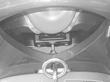
9 Your watercraft s hull and engine identification numbers are important for model identification when registering your watercraft, when obtaining insurance, and when ordering replacement parts. The hull identification number is located on the rear right-hand boarding platform (1). The engine identification number is located at the front of the engine near the stator cover (2). IDENTIFICATION NUMBERS Record your vehicle s identification numbers in the spaces provided and in another location away from the vehicle. If the vehicle is destroyed or stolen, you ll have the identification numbers required by insurance and/or law enforcement. NOTE: Check with your insurance agent about obtaining insurance coverage for your watercraft, or see your Polaris dealer. Purchase Date: 1 Vehicle Model Number: Engine ID Number: 2 Hull ID Number: 7
10 SAFETY Signal Words and Symbols The following signal words and symbols appear throughout this manual and on your vehicle. Your safety is involved when these words and symbols are used. Become familiar with their meanings before reading the manual. CAUTION A caution indicates a situation that may result in damage to the vehicle. The safety alert symbol, on your vehicle or in this manual, alerts you to the potential for personal injury. NOTE: A note will alert you to important information or instructions. WARNING The safety alert warning indicates a potential hazard that may result in serious injury or death. CAUTION The safety alert caution indicates a potential hazard that may result in minor personal injury or damage to the vehicle. 8
11 Safety Decals Important warning and instruction decals have been placed on the watercraft for your protection. Read and follow the instructions on each decal carefully. If any decal becomes illegible or comes off, contact your Polaris dealer for a replacement. Any safety decal needing replacement will be provided by Polaris at no charge. The warning decals summarize and highlight key safety and operational information. Be sure to read the entire owner s manual for details that affect safe operation of this watercraft. SAFETY 9

12 SAFETY Safety Decals The general safety/warning decal is located on the rear of the watercraft, just below the seat. 10
13 Safety Decals The collision warning decal is located on the dash of your watercraft. SAFETY Collisions result in more INJURIES AND DEATHS than any other type of accident for personal watercraft (PWC). TO AVOID COLLISIONS: SCAN CONSTANTLY for people, objects and other watercraft. Be alert for conditions that limit your visibility or block your vision of others. OPERATE DEFENSIVELY at safe speeds and keep a safe distance away from people, objects, and other watercraft. Do not follow directly behind PWCs or other boats. Do not go near others to spray or splash them with water. Avoid sharp turns or other maneuvers that make it hard for others to avoid you or understand where you are going. Avoid areas with submerged objects or shallow water. TAKE EARLY ACTION to avoid collisions. Remember PWCs and other boats do not have brakes. DO NOT RELEASE THROTTLE WHEN TRYING TO STEER away from objects - you need throttle to steer. Always check throttle and steering controls for proper operation before starting PWC. Follow navigation rules and state and local laws that apply to PWCs. See Owner s Manual for more information. 11


14 SAFETY Safety Decals The fuel warning decal is located near the fuel tank fill cap. The capsize warning decal is located at the rear of the watercraft, positioned upside down so the operator can read it when the boat is capsized. WARNING RIGHTING CAPSIZED BOAT To prevent injury, do not place hands or objects into pump inlet, intake grate or nozzle. To prevent major engine damage: Make sure engine is stopped by pulling lanyard from engine stop switch and turn boat to upright position in a clockwise direction

15 Informational Decals The Coast Guard exemption decal is located below the left-hand mirror. SAFETY Located on the upper shroud near the front compartment door: FIRE EXTINGUISHER CONTAINER LOCATED INSIDE Located on the engine water manifold: WARNING Do Not Remove Electrical Part When Starting Or During Operation. High Voltage Shock Hazard
16 SAFETY Operator Safety WARNING Failure to follow the warnings and instructions contained throughout this manual and on your vehicle can result in severe injury or death. Read and understand your owner s manual and all warning decals before operating a Polaris watercraft. Any operator of a Polaris watercraft must know and practice the following guidelines for personal safety and the safety of passengers. Never permit a guest to operate this watercraft unless the guest has read and understands all warning decals and the owner s manual. Operator Guidelines This watercraft is not a toy. It s a high performance powerboat, and operating it requires learned and practiced skills. All operators and passengers should become familiar with proper operating techniques before attempting maneuvers. Always operate the watercraft at a speed appropriate for water conditions and for your level of experience. The minimum recommended age for operators of this watercraft is 16 years, but operators between 16 and 18 years of age may require close adult supervision. Obey all applicable boating rules and regulations. This watercraft does not have brakes. The watercraft is stopped by releasing the throttle. The vehicle will glide to a stop due to the natural drag of the water. Allow a minimum of 300 feet (90 m) to coast to a stop from full throttle. Jet thrust is required to steer and turn the vehicle. Never completely release the throttle and attempt to turn at more than a trolling speed. The watercraft will not turn. Practice until you re comfortable with turning and stopping, and be sure you ve mastered the skills before carrying a passenger. Learn and observe all local, state, and federal boating regulations and speed limits. Boating laws and navigational rules are designed for the safety of everyone sharing the waterways. 14
17 Operator Safety Your Polaris watercraft is capable of towing, but please be aware that towing can cause reduced steering control. Be extremely careful when towing other watercraft, skiers or objects behind this watercraft, as they have a significant impact on handling and steering. Observe local and state laws regarding water skiing and towing. Do not allow passengers to stand on the boarding platform while the watercraft is running or in motion. Passengers should always remain seated. Never travel over a ski jump or attempt to jump waves, wakes or other objects in the water. Doing so may severely damage the watercraft and cause personal injury due to the hard impact, a temporary loss of visibility, possible loss of control and reduced reaction time. SAFETY Always securely attach the lanyard cord (1) to the operator s left wrist or PFD before starting the watercraft. If the operator falls off, the engine will immediately lose power. Be sure the lanyard cord is free and not wrapped around the handlebars or controls. When the watercraft is not in service, disconnect the lanyard from the engine stop switch to prevent accidental starting of the engine. 1 15
18 SAFETY Operator Safety Safe Riding Gear Always wear protective clothing when operating or riding a personal watercraft. Consider attaching a whistle to your lanyard to summon help in emergency situations. 1 - Personal Floatation Device The operator and passenger must always wear an approved personal flotation device (PFD) at all times to prevent accidental drowning. Polaris recommends a vest-type PFD (U.S. Coast Guard type 1, 2, or 3). NOTE: The seat of the watercraft is not a PFD. 16 WARNING Failure to wear protective clothing while operating a watercraft can result in serious injury. The jet pump emits a forceful stream of water that can injure body orifices. Falling off the watercraft while operating at higher speeds may also lead to injury. Always wear the recommended protective gear while riding on any watercraft. 2 - Eye Protection Wear adequate eye protection to protect against water spray, sun, insects and other objects. To protect prescription eyewear and sunglasses against loss or damage, wear goggles that fit securely over them. 3 - Suit/Shoes/Gloves We recommend that all riders wear a wet/dry suit and watercraft shoes to protect against the force of the water, as well as exposure and unknown hazards in the water, such as debris and hidden objects. Riding gloves may also be considered. NOTE: A helmet may provide increased personal injury protection in some situations, such as impact with the watercraft or during a collision with other watercraft or an obstacle. However, a helmet may not provide adequate protection against all foreseeable impacts and may aggravate some injuries. For example, if a rider falls off a moving watercraft while wearing a helmet, the helmet could catch the water and cause choking, severe and permanent injuries or death. A helmet may also increase the possibility of an accident if it reduces your visibility or ability to hear or if its weight contributes to fatigue

19 Operator Safety Overloading the Watercraft WARNING Overloading a watercraft will significantly reduce vehicle stability and control, which could result in an accident and lead to severe injury or death. Never allow more than the specified rider capacity on the watercraft. Polaris watercraft are designed to carry an operator and up to three passengers, depending on the model. Check the specifications section beginning on page 102 to determine your boat s rider capacity. When more than one person is riding, the watercraft handles differently, which means that the operator must have enough prior riding experience to handle the watercraft with one or more passengers aboard. SAFETY Fire Safety Federal regulation requires that all watercraft carry an approved fire extinguisher. The operator is responsible for providing and maintaining the fully charged fire extinguisher in the watercraft. Do not operate the watercraft without a fire extinguisher on board. Stow your fire extinguisher under the front storage compartment in the cut-out area of the flotation foam. Know how to reach the extinguisher quickly in case of fire, and know how to use it before you operate the personal watercraft. If you have any doubts about your ability to extinguish a fire, swim away from the craft as quickly as possible. Immediately seek help from other boaters or people on shore. 17

20 SAFETY Operator Safety Weather and Darkness Be aware of severe weather conditions. Observe weather forecasts and conditions before venturing out, and do not operate the watercraft when visibility is poor and when the water is rough. Operation of the watercraft in poor weather conditions can result in an accident and lead to severe injury, hypothermia or death. Never operate the watercraft after sunset, before sunrise or in any condition of darkness. The vehicle is not equipped with lights, which makes it unsafe and illegal to operate in darkness. Consult local regulations concerning allowed hours of operation. Always ride with another watercraft when operating in remote areas or in large areas of open water. Carry a flare gun on board to signal for help if necessary. Protective Apparel Normal swimming attire may not provide adequate protection while riding a watercraft. At the rear of the watercraft, the jet pump emits a forceful stream of water that can injure body orifices, such as mouth, eyes, ears, rectum and vagina. In addition, falling off the watercraft while operating at higher speeds may lead to injury due to impact with the water. All riders must wear wet suit bottoms or clothing that provides equivalent protection. NOTE: If a passenger falls from the watercraft, release the throttle immediately. Do not exceed idle speed if any person is within 50 feet (15 m) of the rear of the watercraft. 18
 deep, and do not operate at more than an idle speed in water that is less than six feet deep.")
21 Operator Safety Obstacles and Shallow Water Always be on the lookout for dangerous obstacles above and below the water surface, especially in shallow water. Use extra caution when riding in unfamiliar areas. Never ride in water that is less than two feet (60 cm) deep, and do not operate at more than an idle speed in water that is less than six feet deep. Colliding with an underwater object could result in severe injury or death. Ingesting sand into the cooling system will also cause the engine to overheat, which could lead to serious mechanical damage. SAFETY If the watercraft has been beached or has been sitting in shallow water, clear out any sand or small rocks before boarding and restarting the watercraft. Remove the particles by bouncing the back of the machine up and down in at least two feet of water. If the craft has been beached, flush the cooling system. CAUTION Failure to flush the cooling system after the watercraft has been beached could result in serious engine damage. Always follow the recommended flushing procedures and flush the cooling system any time the watercraft has been beached. 2 ft. (60cm) Minimum 19
22 SAFETY Operator Safety Turning and Accelerating Turning and accelerating without checking for other boats and objects in your path can cause an accident and result in severe injury or death. Always look behind the watercraft and to each side before accelerating and before making sudden turns. Always be aware of obstacles, swimmers and other watercraft. Quick turns or abrupt changes in speed can cause passengers to lose their balance and be ejected from the vehicle, which could result in injury. The operator should always alert any passengers before making sudden turns or changes in speed. Pre-Operation Check Always perform the pre-operation check (beginning on page 38) before starting and riding the watercraft. Make sure all critical components are operating correctly. Check fuel and oil levels and all controls, especially the throttle lever, handlebars, and steering nozzle. Failure of these critical components can result in an accident and lead to severe injury or death. Service and Maintenance Routine service and adjustments to the watercraft are critical for the safe operation and extended life of the watercraft. Follow the maintenance and service recommendations outlined in this manual. 20
23 Operator Safety Jet Pump Water Intake Safety Contact with the jet pump or driveline components of the watercraft can result in severe injury, death or drowning. Do not allow hands, feet, ropes, straps, clothing or long hair to come in contact with the jet pump water intake (1) on the bottom of the watercraft while the engine is running. Never insert any object into the intake or outlet (2) of the jet pump, and never start or operate the watercraft with the inlet grate, ride plate (3), or any guards or shields removed. To prevent serious injury due to accidental starter engagement, be sure the engine is off and the safety lanyard is disconnected before removing weeds or debris that may have collected in or around the jet pump intake SAFETY Electrical Shock Hazard Never touch or remove electrical parts while starting or during operation of the watercraft. Severe injury or death could result from electrical shock. Safe Riding Position Falling off a watercraft can result in serious injury. The operator and any passengers should always keep both feet firmly planted on the floorboards while the watercraft is in motion. The passenger should face forward and firmly hang on to the operator s waist, except in towing situations, when the spotter faces the rear and uses the grab handle to hold on. Lifting the Watercraft Severe back injury or other injury could result from attempting to lift the watercraft without assistance. Never attempt to lift the watercraft without the aid of a trailer and winch or another heavy lifting device. 21
24 SAFETY Operator Safety Operator Awareness A collision can cause severe injury or death. Always be aware of other watercraft, swimmers and other obstacles while operating the watercraft. Always maintain a safe distance, especially if you re an inexperienced operator. Do not exceed idle speed if any person is within 50 feet (15 m) of the rear of the watercraft. Operator Fitness Safe operation of this rider-active craft requires good judgement and physical skills. Persons with cognitive or physical disabilities who operate this vehicle have an increased risk of overturns and loss of control, which could result in serious injury or death. Riding personal watercraft is strenuous. All riders should be in good physical condition. Pregnant women should consult their physicians before riding any watercraft. Reboarding the watercraft in deep water can also be strenuous. Operators and passengers should be physically fit enough to reboard the watercraft in deep water. Practice boarding in chest-deep water to be sure you are physically able to reboard if the need arises. Boating Under the Influence Operating any watercraft while under the influence of alcohol or drugs could result in an accident and lead to severe injury or death. More than half of all the people who drown have consumed alcohol prior to their accident. Even if you re not intoxicated, any amount of alcohol can be a threat to your safety and the safety of others. The equivalent of one beer will impair your balance, vision, judgment and reaction time, making you a potential danger to yourself and others. Do not operate any watercraft while under the influence of alcohol or drugs. 22
25 Operator Safety Vehicle Modifications Modifications to this machine could create safety hazards and reduce vehicle reliability as well as make it unsafe or illegal to operate. Do not modify this watercraft or any of its components. Any modifications to the watercraft will void your warranty. Operator Fatigue and Dehydration Long hours of boating with exposure to noise, vibration, sun, glare and wind can result in operator fatigue and dehydration. These conditions can affect your balance, vision, judgment and reaction time. Fatigue and dehydration can increase your risk of an accident resulting in bodily injury or death. Combining alcohol consumption with this condition greatly increases your risk of causing an accident. Learn to recognize the early symptoms of fatigue, and allow your body to recover by taking a break from operating the watercraft. Drink plenty of non-alcoholic beverages to prevent dehydration, and wear protective riding gear to protect against exposure to weather elements. SAFETY Hypothermia Your life may depend on a clear understanding of the effects of cold water on the human body. Many suspected drowning victims actually died from cold exposure (hypothermia) rather than drowning. Hypothermia can begin in water as warm as 80 F. (27 C). It s a condition in which the body loses heat faster than it can produce it. Violent shivering develops, which may give way to confusion and a loss of body movement. Hypothermia can result in severe injury or death in a very short time. To avoid hypothermia: Dress warmly. Wear proper gear and stay as dry as possible. Seek a warm environment at the first sign of hypothermia (mild shivering). If you fall into the water: Do not discard clothing. While wearing your life jacket, draw your knees up toward your chest and hold them there with your arms in the Heat Escape Lessening Posture (HELP). 23
26 FEATURES AND CONTROLS 1. Starter Button - Depress and hold the starter button to start the engine. Release it as soon as the engine starts. Do not depress for more than ten seconds at a time. NOTE: The lanyard and lock plate must be attached to the engine stop switch to start the engine 2. Stop Switch/Lanyard - Push this switch down or disconnect the lanyard plate to stop the engine quickly. 3. Safety Lanyard Wrist Cord - The lock plate end is attached to the stop switch. The wrist band is attached to the operator s wrist or PFD. The engine will not start unless both are attached. 4. Gauge Mode Button - This button operates the display change for the NGI. See page Throttle - Squeeze the throttle lever toward the handlebar to increase speed. Release the lever to slow the craft and return the engine to idle. NOTE: The throttle lever installed on your MSX is finger-operated, but Polaris also offers an accessory thumb-operated lever. See your Polaris dealer for more information. 6. Instrumentation - Instrumentation is New Generation Instrument (NGI). See page 30 for a detailed explanation of the NGI display. 7. Seat Latch - The seat latch secures the seat in position. When released, it provides access to the engine compartment. 8. Jet Pump Outlet Nozzle - The nozzle is the exit for the jet output. Orientation is controlled by the handlebars and determines the direction of craft movement. 9. Exhaust Outlet 10. Reverse Gate 11. Drain Plugs - When water gets into the bilge, it can be drained through the drain plugs. Remove the watercraft from the water before draining the bilge. Be sure the plugs are securely installed before launching the craft. 12. Fuel Tank Fill - The fuel fill is located under the front compartment door. Turn the cap counterclockwise to remove, clockwise to replace. 13. Oil Fill - The oil fill is located under the front compartment door. Turn the cap counterclockwise to remove, clockwise to replace. 14. Jet Pump Intake Grate - The grate protects the impeller and drive shaft and protects riders from contact with components. 15. Drive Shaft - Beneath the intake grate, the drive shaft transmits power from the engine to the impeller. 16. Ride Plate - The ride plate covers and protects the jet pump and provides leveling control for the craft. 24


27 1 4 FEATURES AND CONTROLS
28 FEATURES AND CONTROLS 1. Front Compartment Door- The door provides access to the fire extinguisher, oil tank, fuel fill, oil fill and main storage space. 2. Fire Extinguisher Compartment - Located under the front compartment door and under the storage bucket in the left side flotation foam, this compartment provides secure storage for the fire extinguisher. 3. Handlebars - The handlebars control the orientation of the jet pump outlet nozzle, which in turn controls the direction of craft movement. 4. Console Storage 5. Seat/Engine Compartment - Removing the seat provides access to the engine, battery, electrical box, exhaust system, and other components. 6. Grab Handle - The grab handle assists riders while boarding the craft or when riding as passengers. 7. Tow Eye/Hook - Securely attach the tow rope to this hook when pulling skiers, wake boarders and tubes. 8. Boarding Platform/Footwell Pads - The boarding platform assists riders while boarding. The footwell pads are the place for the operator s and passenger s feet while riding the watercraft. 9. Sponson -The sponson enhances vehicle stability and turning ability in water. 10. Reverse Operation Handle 26

29 FEATURES AND CONTROLS
 11. Spark arrestor/air filter 12.")
30 FEATURES AND CONTROLS Engine Components (under seat) 1. Battery 2. Engine Management Module (EMM) 3. Spark plugs 4. Air intake cover 5. Starter solenoid 6. Exhaust silencer 7. Exhaust pipe 8. Exhaust cooling water hose 9. Cooling water manifold 10. Thermostat assembly (under end of water manifold) 11. Spark arrestor/air filter 12. Engine cooling water outlet hose (under thermostat assembly)
31 Engine Components FEATURES AND CONTROLS 4,

32 FEATURES AND CONTROLS New Generation Instrument (NGI) Primary Functions Speedometer Clock Tachometer Engine Hourmeter Trip Odometer Oil Level Fuel Level Low Oil/Pressure/Fuel/ Battery Voltage Warnings High Engine Temperature Warning Check Engine Warning Accessible Functions Tachometer Engine Hourmeter Trip Odometer 30
33 New Generation Instrument (NGI) Function Overview Speedometer The large numeric speedometer displays vehicle speed. The NGI receives signals via a paddle wheel located on the ride plate. The gauge interprets these signals and computes actual vehicle speed. Tachometer The NGI has the ability to display between 0 and 9950 RPM. The gauge receives the tachometer signal from the EMM. Display tolerance is ± 100 RPM. Oil Level Oil level is displayed with a 7-bar LCD graphic. Oil levels are displayed in 1/7th increments. When the display is 1/7th (one bar), a LOW OIL symbol and red LED warning light will blink to alert the operator to the low oil condition. Refill the oil tank. CAUTION Operating the engine without oil will result in serious engine damage. Always add oil when the level is low. FEATURES AND CONTROLS Fuel Level Fuel level is displayed with an 8-bar LCD graphic. The level is displayed in 1/8th increments. When the display is 1/8th (one bar) or less, a LOW FUEL symbol and red LED warning light will blink to alert the operator to the low fuel condition. Refill the fuel tank. Engine Hourmeter The NGI retains and displays up to hours. Additional hours will not reset the gauge to zero. The gauge begins to record engine hours whenever the engine RPM is 500 RPM or higher. Memory retention is approximately 10 years. Clock The NGI displays the time in the main display mode without reference to either AM or PM. Trip Odometer The NGI will display accumulated miles or kilometers traveled. Engine RPM must be at or above 500 before the gauge will begin recording the distance traveled. 31
34 FEATURES AND CONTROLS New Generation Instrument (NGI) Instrument Operation DISPLAY MODE There are three different display modes the gauge uses to display information to the operator. The three modes are: MAIN MODE, SPEED/TACHOMETER MODE and NAVIGATION MODE. Press and release the MODE button on the left handlebar control to advance through the three modes. MAIN MODE displays SPEED and CLOCK. SPEED/TACHOMETER MODE displays SPEED and TACHOMETER. NAVIGATION MODE displays SPEED, TRIP ODOMETER and ENGINE HOURS. CLOCK SET In the main mode, press and hold the RESET button until the hour digits flash (approximately six seconds). Press the RESET button to advance the hour digits. Press the MODE button to stop the hour flash and begin the minute digits flash. Press the RESET button to advance one minute. Press the MODE button to set the clock and exit the clock set mode. TRIP ODOMETER RESET Press and hold the RESET button until the trip odometer is reset to miles / km. CHANGE UNITS OF MEASURE To toggle between English and metric units of measure, press and hold the MODE button for ten seconds. 32
35 New Generation Instrument (NGI) Display Warnings The NGI will alert the operator to the following conditions: LOW FUEL (Fuel level reaches 1/8 level.) LOW OIL (Oil level reaches 1/7 level.) LOW BATTERY VOLTAGE (Battery voltage is at or below 10.9 vdc) HIGH TEMPERATURE (Temperature is monitored by EMM) CHECK ENGINE (Check engine warning is triggered by EMM) Regardless of warning, each warning will display a related ISO symbol on the screen and a blinking red LED warning. FEATURES AND CONTROLS 33
36 FEATURES AND CONTROLS RPM Limiter CAUTION A clogged intake and/or impeller can cause engine overheating and/or damage to the jet pump and impeller parts. Always keep the intake and/or impeller free of debris and weeds. Your Polaris watercraft is equipped with a device that will limit engine revolutions per minute (RPM) if the engine overheats. This feature is designed to help prevent engine damage caused by engine overheating. If the high temperature indicator and warning displays, stop the engine immediately. Clean the jet pump and impeller as outlined on page 24. If the cause of overheating is identified and corrected, normal operation can be resumed by releasing and reapplying the throttle. If the engine continues to overheat after cleaning the jet pump and impeller, take the watercraft to an authorized Polaris dealer for service. 34
37 Standard Equipment Watercraft Owner s Safety and Maintenance Manual Watercraft Safety Video PN Lanyard with wristband, lock plate and whistle Tool Kit containing: wrench, flat screwdriver, Allen wrench, spark plug wrench with Phillips head screwdriver Contact an authorized Polaris dealer for replacement parts and equipment. Provide part numbers when possible. Accessories Polaris has a wide range of watercraft accessories, from wetsuits and life vests to accessory mirrors, touring and towing gear, and performance parts. Contact your Polaris dealer or visit to see our full line of available products. FEATURES AND CONTROLS Optional Equipment See page 101 for a list of Polaris products for servicing your watercraft. U.S. Coast Guard-approved fire extinguisher (UL 5-B:C Rating) PN Registration numbers (see your Polaris watercraft dealer) Tow rope (for emergency use) PN Flare gun (for emergency use) PN Safety and riding gear, including approved personal flotation devices for operator and passenger (see your Polaris watercraft dealer) 35

38 EMISSIONS EPA Emissions Regulations All direct injection equipped engines manufactured by Polaris Industries are certified to the United States Environmental Protection Agency regulations for the control of air pollution. For this reason, factory procedures for servicing must be strictly followed, and wherever practicable, returned to the original intent of the design. Maintenance, replacement, or repair of the emission control devices and systems may be performed by any marine SI engine repair establishment or individual. Refer to the California Emission Control System Limited Warranty beginning on page 107. California Star Labels A star label has been applied to your personal watercraft in accordance with the requirements of the California Air Resources Board. The star label means cleaner marine engines. Cleaner Air and Water - for healthier lifestyle and environment. Better Fuel Economy - burns up to percent less gas and oil than conventional carbureted two-stroke engines, saving money and resources. Longer Emission Warranty - protects consumer for worry free operation. The MSX 140 HO engine has been certified as: 36
39 California Star Labels One Star - Low Emission The one-star label identifies engines that meet the Air Resources Board s 2001 exhaust emission standards. Engines meeting these standards have 75% lower emissions than conventional carbureted two-stroke engines. These engines are equivalent to the U.S. EPA s 2006 standards for marine engines. Two Stars - Very Low Emission The two-star label identifies engines that meet the Air Resources Board s 2004 exhaust emission standards. Engines meeting these standards have 20% lower emissions than One Star - Low Emission engines. EMISSIONS Three Stars - Ultra Low Emission The three-star label identifies engines that meet the Air Resources Board s 2008 exhaust emission standards. Engines meeting these standards have 65% lower emissions than One Star - Low Emission engines. 37
40 OPERATION Pre-Operation Inspection Use the Pre-Operation checklist beginning on page 39 to verify that your vehicle is in proper operating condition before each use. Procedures are outlined in further detail on the pages following the checklist. WARNING If a proper inspection is not performed before each use, severe injury or death could result. Always inspect the vehicle as outlined in the checklist before each use to ensure it s in proper and safe operating condition. See page 75 for additional inspection information. Always remove the lanyard from the engine stop switch before performing the pre-operation inspection. WARNING Starting or operating the watercraft with a fuel leak can result in an explosion, causing serious injury or death. If you smell fuel in the hull of the craft, do not start the vehicle. Take it to your dealer immediately for inspection. 38
41 Pre-Operation Inspection OPERATION Item What To Do Item What To Do Bilge Fuel/oil tank levels Jet pump water intake Drain water from the bilge before putting the craft in the water. Check fuel/oil; add as necessary; inspect for presence of water. Inspect and remove any debris; ensure intake grate is secure; push rear of craft up and down in the water to flush sand out of water intake before starting. Battery Hull Drain plugs/bilge Loose parts/ hoses Seat Check fluid level/condition; vent hose must be clear and open. Inspect hull for damage or cracks; clean off any marine growth. Inspect; clean; be sure each plug is tight, secure and doesn t leak. Inspect for loose parts/hoses and connections; tighten as needed. Check and secure latches. Throttle Steering Fire extinguisher Storage compartment Engine cover (seat) Check for proper operation. Check for proper operation; inspect control cable. Inspect condition/expiration date. Check and secure latches. Remove and ventilate engine compartment before starting engine. Re-secure latches. Loose ropes/ straps/clothing/ long hair Riding gear Switches/buttons Lanyard cord/ stop switch Reverse System Be sure that there are no loose ropes, straps, clothing, etc.; Long hair is tied back and secured. Check operator and passenger for complete gear and proper fit. Check for proper operation. Check condition and operation. Check for proper operation. 39
42 OPERATION Pre-Operation Inspection Fuel WARNING The engine exhaust from this product contains chemicals known to cause cancer, birth defects or other reproductive harm. Operate this vehicle only outdoors or in well-ventilated areas. WARNING Gasoline is highly flammable and explosive under certain conditions. Always heed the following warnings pertaining to gasoline and fumes. Always remove the seat an ventilate the engine compartment before starting the engine. Always check for fumes prior to starting engine. Always exercise extreme caution whenever handling gasoline. Always refuel with the engine stopped and outdoors or in a well ventilated area. Do not smoke or allow open flames or sparks in or near the area where refueling is performed or where gasoline is stored. Do not overfill the tank. Do not fill the tank neck. If gasoline spills on your skin or clothing, immediately wash it off with soap and water and change clothing. Never start the engine or let it run in an enclosed area. Gasoline powered engine exhaust fumes are poisonous and can cause loss of consciousness and death in a short time. 40
43 Pre-Operation Inspection Fuel CAUTION Using a non-recommended fuel may cause serious engine damage. Polaris recommends the use of 87 octane (or higher) non-oxygenated or 89 octane (or higher) oxygenated fuel only. Your watercraft features an oil injection system, and it s not necessary to pre-mix the gasoline and oil. Refer to the specifications section beginning on page 102 for the proper fuel octane and oil requirements for your Polaris watercraft. WARNING Failure to follow proper refueling instructions can result in fire or explosion, causing severe injury or death. Always stop the engine and disconnect the lanyard from the engine stop switch before refueling. OPERATION Refueling Carefully remove the fuel cap. NOTE: Keep the watercraft horizontal while fueling. The use of a funnel or flexible spout will help avoid gasoline spillage on the watercraft. Always wipe up any spills immediately. Wash out the footwells with water if fuel or oil spills in those areas. Use fresh, seasonal gasoline that has been stored in a clean container. For the best performance from gasoline, purchase only what is needed for a month or less of operation. NOTE: If the fuel or oil levels become low, a warning light will flash on the NGI display. Proceed to shore and refuel. 41
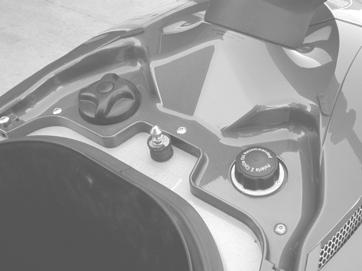
44 OPERATION Pre-Operation Inspection Oil CAUTION Mixing brands or using a non-recommended oil may cause serious engine damage. We recommend the use of Polaris synthetic 2-cycle oils. Never mix oil brands. The oil fill cap (1) is located 1 under the front compartment door. Check the oil level before each use of the vehicle and add oil as necessary. Make sure the engine is off and the safety lanyard is removed from the engine stop switch before adding oil. Polaris synthetic 2-cycle oils are formulated to work with your watercraft engine. They ve been thoroughly tested to provide the ultimate in performance and protection. Our biodegradable synthetic 2-cycle oil is also environmentally friendly. See page 101 for part numbers of Polaris products. 1. Place the watercraft in a level position. 2. Remove the oil fill cap and check the oil level. 3. Add the recommended oil. Fill to within several inches of the fill hole opening. NOTE: Do not fill all the way to the opening. Wipe up any spills immediately. 4. Visually inspect the oil for water or foreign matter. If either is present, see your Polaris dealer for service. A warning light on the NGI display will flash if oil is low (1/8 tank or less). Add oil promptly. CAUTION If the engine is operated without oil, severe damage will occur. If you discover an empty oil tank, see an authorized Polaris dealer immediately for service. Severe engine damage will occur if water becomes mixed into the oil. Always tighten the oil fill cap securely. 42
45 Pre-Operation Inspection Jet Pump Intake 1. Ride Plate 2. Impeller 3. Drive Shaft 4. Intake Grate 1 4 OPERATION 1. Remove the lanyard lock plate from the stop switch and disconnect the battery cables before inspecting the jet pump intake. Disconnect the negative (black) cable first. 2. Carefully check the jet pump intake and remove any weeds, shells or other debris that may restrict the intake of water. 3. After launching, walk the watercraft into water at least two feet (60 cm) deep and bounce the back of the craft up and down several times to flush out any sand and debris that may be in the pump. 2 WARNING Improperly connecting or disconnecting battery cables can result in an explosion and cause serious injury or death. When disconnecting cables, always disconnect the negative (black) cable first. When reconnecting, always connect the negative (black) cable last. 3 CAUTION A clogged intake or the ingestion of sand into the cooling system will cause engine overheating and result in jet pump or engine damage. If any obstruction cannot be removed, have an authorized Polaris dealer service it immediately. Clear the pump of sand after operating in shallow water or after beaching the watercraft. 43


")
46 OPERATION Pre-Operation Inspection Steering Check the handlebars for free movement throughout their full range. Make sure the jet pump outlet nozzle changes direction as the handlebars are turned from left to right and vice versa. Be sure the handlebars and handlebar grips fit snuggly. Visually inspect the control cable to ensure that it s in working condition. Throttle Always check throttle operation prior to starting the engine. Pull or squeeze the throttle several times to be sure the throttle lever moves freely through its full range. It should spring back to its original position when released. Engine and Storage Compartments If the craft is operated in salt water, spray the inside of the hull (engine and components) with waterproof lubricant spray after every use. See page 101 for part numbers of Polaris products. The engine compartment is located beneath the seat. Be sure the seat, engine cover and front compartment door are properly positioned and securely latched before operating the watercraft. 44
. Always remove the seat and ventilate the engine compartment before starting the engine.")

47 Pre-Operation Inspection Loose Parts Inspect the watercraft for any loose nuts, bolts, fasteners and hoses. Be sure that all hose clamps are tight. Replace cracked or deteriorating hoses. Seat To access the engine/storage compartment, disengage 1 the rear seat latch (1). Always remove the seat and ventilate the engine compartment before starting the engine. Be sure all seats are properly positioned and secure before operating the watercraft. NOTE: The seat is not a personal flotation device (PFD) and will not provide life-saving flotation. Always wear a PFD when operating or riding a watercraft. OPERATION Fire Extinguisher The operator of the watercraft is required by law to carry a fire extinguisher on board. Always keep a fully charged and working fire extinguisher inside the fire extinguisher holder, which is located inside the storage area under the front compartment door. A fire extinguisher is not standard equipment with this watercraft. Contact your Polaris dealer or a fire extinguisher dealer to purchase a U.S. Coast Guard-approved fire extinguisher with a UL 5-B:C rating. 45
48 OPERATION Pre-Operation Inspection Battery WARNING Causing sparks while servicing the battery or servicing the battery when gas fumes are present can result in an explosion, causing serious injury or death. Never create a spark while servicing the battery. If you smell fuel in the craft, do not service the battery. Take the watercraft to your dealer immediately for inspection. Confirm that the battery terminal connections are tight, and make sure the battery is securely fastened in its mounting position. Inspect the battery for leaks, and check the vent hose for kinks or blockage. 1 Check the battery fluid level and add only distilled water if the level is low. Tap water contains minerals that are harmful to a battery. Maintain the fluid level between the upper and lower marks (1) on the battery. Keep the battery in good condition and fully charged at all times, as a weak battery can leave you stranded. Never operate the watercraft with a battery that s too weak to start the engine or shows signs of loss of power. Use a trickle charger to maintain the battery s charge during the off season. Doing so will ensure a good battery at the end of the storage period and a longer life for the battery. NOTE: The Polaris Battery Tender battery charger can be left connected during the storage period and will automatically charge the battery if the voltage drops below a pre-determined point. See your dealer or visit our online store at 46
49 Pre-Operation Inspection Hull Use a non-abrasive cleaner to remove any marine growth and inspect the hull for cracks or damage. Do not operate the watercraft if the hull is damaged. Drain Plugs and Bilge Turn each bilge drain plug (1) counterclockwise and remove it. Clean the plug and plug hole of any sand and debris before reinstalling. Do not operate the watercraft if any drain plug is loose or missing. When the watercraft is out of the water, remove the drain plugs and carefully flush out the bilge with fresh water. Allow the bilge to drain completely. Wipe out the bilge with dry shop towels and reinstall the drain plugs. After launching the craft, remove the seat and check for leaks. 1 OPERATION Riding Gear Be sure all operators and passengers have the appropriate riding gear, including a PFD (see page 16). Make sure all trailing objects are securely tied back or stowed. WARNING Objects trailing from a person in the water or from the watercraft can easily become entangled in the jet pump impeller and cause severe injury or death. Make sure long hair, straps, ropes, clothing and similar objects are tied back and secured. 47
50 OPERATION Pre-Operation Inspection Switches/Buttons Perform these checks while the watercraft is in the water: 1. Check the inside of the engine compartment for fuel or water leaks. Do not operate the watercraft until any leaks have been repaired and the engine compartment has been ventilated. 2. Start the engine and let it run for a few seconds. Remove the lanyard lock plate (1) from the engine stop switch (2) to test operation. The engine should stop immediately. If it doesn t, press the stop switch to stop the engine. Do not ride the watercraft. See your Polaris dealer for service before operating the watercraft If removing the lanyard lock plate successfully stopped the engine in the previous step, start the engine again and allow it to run for a few seconds. Depress the engine stop button. If the engine doesn t stop immediately, remove the lanyard lock plate to stop the engine. Do not ride the watercraft. See your Polaris dealer for service before operating the watercraft. 48
51 Principles of Operation The engine is directly coupled to a driveshaft. When running, the driveshaft rotates the impeller. The impeller is positioned so that water is drawn up from beneath the watercraft. The water travels through the impeller and is accelerated, producing thrust to move the watercraft forward. Pulling or squeezing the throttle lever increases engine speed (watercraft speed). Turning the handlebar pivots the jet pump nozzle (water outlet) which controls the watercraft s direction. The throttle must be applied in order to turn the watercraft. Engine Break-in Procedure The break-in period for your new Polaris watercraft is defined as the time it takes to use the first full tank of gasoline. No single action on your part is as important as following the procedures for a proper break-in. Careful treatment of a new engine will result in more efficient performance and longer life for the engine. Perform the following procedures carefully. CAUTION OPERATION Excessive heat build-up during the first three hours of operation will damage close-fitted engine parts. Do not operate at full throttle or high speeds for extended periods during the break-in period. Do not carry passengers during the break-in period. Use of any oils other than those recommended by Polaris may cause serious engine damage. We recommend the use of Polaris synthetic 2-cycle oils for your Polaris watercraft. 49
52 OPERATION Engine Break-in Procedure CAUTION If the engine is operated while the watercraft is in very shallow water, sand, weeds and debris may be sucked into the jet intake and could cause damage to the impeller or injury to bystanders. Ingesting sand into the cooling system will cause the engine to overheat, which could lead to engine damage. Whenever starting the engine, always be sure the watercraft is in water at least two feet (60 cm) deep. 1. Make sure the drain plugs are installed securely and launch the watercraft. 2. Push the rear of the watercraft up and down several times in the water. 3. Check the throttle for free operation. 4. Remove the seat and ventilate the engine compartment. 5. Secure the seat, board the craft and start the engine. Allow it to warm up for about a minute before departing. 6. Operate the watercraft at the lowest possible speed for the first five minutes of operation. 7. Gradually open the throttle to half speed (half throttle). 8. Vary throttle speeds up to 3/4 speed during the break-in period (first full tank of fuel). 50
53 Navigational Rules This watercraft must be operated in accordance with all navigational rules and regulations governing it and the waterway on which it s operated. These rules are used and enforced internationally, as well as by the U.S. Coast Guard and local law enforcement. Any operator of this watercraft should be aware of these rules and should obey them when encountering other vessels. The following rules are condensed and are provided only for your convenience. Consult a U.S. Coast Guard Auxiliary or Department of Motor Vehicles for a complete set of rules governing the waters where you ll be riding. You may also obtain this information when registering your watercraft. OPERATION Right-of-way and Give-way In nautical terms the stand-on (privileged) vessel has the right-of-way and the give-way (burdened) vessel must yield or give way. Stand-on Vessel The vessel with the right-of-way has the duty to continue its course and speed, except to avoid an immediate collision. By maintaining course and speed, other vessels should be able to determine how best to avoid interfering with its course. Give-way Vessel The give-way vessel is responsible for taking positive action to stay clear of the stand-on vessel. Give-way vessels should not cross in front of stand-on vessels. The give-way vessel should slow down or change direction briefly and cross behind the stand-on vessel. The give-way vessel s actions should be clear and understandable by the stand-on vessel. 51
54 OPERATION Navigational Rules Rule 2 Rule 2 is The General Prudential Rule of the International Rule. This rule states that all operators have the responsibility of taking action to avoid a collision. All vessels involved in a potential collision become give-way vessels. Encountering Vessels There are three main situations in which you may encounter other vessels: Overtaking (passing) Meeting (approaching another vessel head-on) Crossing (traveling across another vessel s path) Meeting Vessels When meeting another power vessel head-on and a collision appears likely, neither vessel has the right-of-way. Both vessels are obligated to alter course to avoid an accident. Keep the other vessel to your port (left) side and take evasive action to the starboard (right) side (1). This rule does not apply if you ll be clear of the other vessel by maintaining your course and speed (2)
55 Navigational Rules Overtaking Vessels If your watercraft is passing another vessel, your craft is the give-way vessel. The other vessel is expected to maintain its course and speed. You must not interfere with its course of travel. If your craft is the stand-on vessel, maintain your course and speed until the other vessel has passed you. OPERATION Crossing Paths When two power vessels are crossing each other s path close enough to run the risk of collision, the vessel having the other on the starboard (right) side must give way. For example, if the other vessel (4) is on your vessel s (3) starboard (right) side, you must give way. If the other vessel is on your port (left) side, your vessel is the stand-on vessel and should maintain its course and direction. The other vessel must give way. However, always drive defensively in case the give-way vessel fails to give your vessel the proper right-of-way. Always be prepared to stop quickly or take evasive action
56 OPERATION Navigational Rules Non-Motorized Craft Non-motorized craft (sailboats, canoes, etc.) are normally given the right-of-way, with the following exceptions: When a non-motorized craft is overtaking a power vessel, the power vessel has the right-of-way. Non-motorized craft should stay clear of fishing vessels. In a narrow channel, a non-motorized craft should not interfere with the safe passage of a power vessel. Fishing Vessel Right-of-Way All vessels that are fishing with nets, lines or trawls are considered fishing vessels under International Rules. Vessels with trolling lines are not considered fishing vessels. Fishing vessels have the right-of-way, regardless of position. However, they must not interfere with the passage of other vessels in narrow channels. 54
57 Navigational Rules Avoid Collisions SCAN CONSTANTLY for people, objects and other watercraft. Be alert for conditions that limit your visibility or block your vision of others. OPERATE DEFENSIVELY at safe speeds, and keep a safe distance away from people, objects and other watercraft. Do not follow directly behind PWCs or other boats. Do not go near others to spray or splash water. Avoid sharp turns or other maneuvers that make it hard for others to avoid you or understand your course of travel. Avoid shallow water and areas with submerged objects. TAKE EARLY ACTION to avoid collisions. Personal watercraft and other boats do not have brakes. DO NOT RELEASE THROTTLE WHEN TRYING TO STEER away from objects. You need throttle for proper steering. Always check throttle and steering controls for proper operation before starting the craft. Follow navigation rules and all state and local laws that apply to personal watercraft. OPERATION Reading Buoys and Markers United States waters are marked for safe navigation through the use of buoys and markers with various shapes, colors, numbers and lights to guide boaters. The same is true for waters in particular states. Marking may vary by geographic location. Consult local authorities before riding your watercraft in unfamiliar waters. Launch Ramp Etiquette Be considerate and efficient when launching your watercraft at a public landing. Prepare your craft in advance, and perform all safety checks before arriving at the landing area. Launch as quickly as possible. 55

58 OPERATION Launching the Watercraft 1. Inspect the drain plugs to ensure they re securely installed. 2. Launch the watercraft in an area free of weeds and debris. Make sure the craft is in at least two feet of water before starting the engine. 3. Push the rear of the watercraft up and down several times to flush out any sand that could be trapped in the pump. 4. Remove the seat to ventilate the engine compartment. Reinstall the seat and latch securely. 5. Carefully board the watercraft and sit down. 6. Start the engine as outlined beginning on page 57. Stopping the Engine Do not turn off the engine until the watercraft has stopped moving. Your craft requires engine power for steering, so after the engine has stopped, you ll lose all steering control of the watercraft. 1. Release the throttle lever. When the engine has slowed to an idle and the craft has stopped moving, push in the stop button. The engine should stop immediately. You may also stop the engine by pulling the lanyard lock plate off the engine stop switch. 2. Be sure the water is at least two feet (60 cm) deep when stopping to prevent debris from entering the impeller or cooling system. 2 ft. (60cm) Minimum 3. Remove the lanyard lock plate. Never leave the lanyard attached to an unattended watercraft. 56
59 Before Starting the Engine Before starting the engine: 1. View the watercraft safety video provided with the watercraft. 2. Read and understand this Owner s Manual. 3. Be familiar with all controls and functions of the watercraft. 4. Perform the pre-operation check found on page 39. If you have any questions about the features or controls of this watercraft, see your Polaris dealer. OPERATION Starting the Engine 1. Attach the lanyard wrist band (1) to your left wrist or PFD. 2. Fasten the lanyard lock plate to the engine stop switch on the handlebars by pushing the lock plate around the barrel of the switch. Be sure the lanyard is not tangled around the handlebars or controls. NOTE: The engine will not start if the lanyard lock plate is removed from the engine stop switch. CAUTION If the engine is run while the watercraft is in very shallow water, sand, weeds and debris may be sucked into the jet intake and could cause damage to the impeller or injury to bystanders. Ingesting sand into the cooling system will cause the engine to overheat, which could lead to engine damage. Whenever starting the engine, always be sure the watercraft is in water at least two feet (60 cm) deep. 57
60 OPERATION Starting the Engine WARNING Starting the engine immediately generates a forward thrust, which could cause an unprepared operator to fall from the machine, causing serious injury or death. Always be seated and alert when starting the watercraft. Never hold the throttle open while starting. 3. Push the starter switch with your left hand while feathering the throttle (very slight open and close motion) with your right hand. As soon as the engine starts, release the starter switch and throttle. Apply just enough throttle to keep the engine running. NOTE: If the engine was run out of fuel, it may take two or three attempts to start the engine. Do not run the starter for more than ten seconds at a time or damage to the starter may result. If the Engine Doesn t Start If the engine does not start within 10 seconds, release the starter switch. Wait 10 seconds before trying again to avoid damaging the starter. CAUTION Engaging the starter improperly may cause starter wear and eventual failure. Do not depress the starter switch while the engine is running or while the starter is spinning. If the engine does not start after several attempts, refer to the troubleshooting section of this manual, beginning on page
 Make sure the watercraft engine is turned off when boarding in deep water. 1. Swim to the rear of the watercraft.")
61 Boarding the Watercraft Practice boarding the watercraft in shallow water before riding in deep water. Any passengers should also practice boarding in the event they must reboard in deep water. Boarding and Starting in Deep Water (Operator Only) Make sure the watercraft engine is turned off when boarding in deep water. 1. Swim to the rear of the watercraft. Grip the boarding handle near the rear of the seat. 2. Pull yourself up onto the boarding platform. 3. Move up to the seat and straddle it. 4. Attach the lanyard lock plate to the engine stop switch and see that the lanyard wrist band is secure on your left wrist before starting the engine. OPERATION Step 1 Step 2 Step 3 59


62 OPERATION Boarding the Watercraft Boarding With a Passenger A watercraft behaves differently with a passenger on board, requiring more operator skill. Practice operating skills alone, before taking a passenger on board. Make sure the watercraft engine is turned off when boarding with a passenger. 1. The operator should board first as outlined on page 59. Attach the lanyard lock plate to the engine stop switch and fasten the lanyard wrist band to the left wrist or PFD. Do not start the engine yet. NOTE: During boarding, the passenger should steady the watercraft while the operator boards. The operator can then help balance it while the passenger boards. 2. The passenger should move (or swim) to the rear of the vehicle. 3. The passenger should pull him/herself on board using the grab handle. Both operator and passenger should try to balance the watercraft while the passenger is boarding. 4. The operator should see that the passenger is holding on tightly and that both feet are on the footrests before starting the engine. Step 1 Step 3 Step 2 Step 4 60
. Do not attempt to activate reverse while moving forward above planing speed. 1. To activate reverse, pull the reverse lever all the way up.")

63 Reverse Operation WARNING Activating reverse while the craft is moving forward could cause loss of control and result in damage to the watercraft or severe personal injury to the operator or passenger(s). Do not attempt to activate reverse while moving forward above planing speed. 1. To activate reverse, pull the reverse lever all the way up. The lever will remain in the full up position (1) Turn the handlebars and apply throttle carefully to maintain steering control of the watercraft. NOTE: Engine RPM is limited during reverse operation. 3. To return to forward operation, allow the engine to return to idle speed, then return the reverse lever to the forward position. OPERATION Turning the Watercraft Turning the watercraft requires using the throttle (thrust from the jet pump) and turning the handlebars at the same time. Do not release the throttle when trying to steer. High thrust makes the watercraft turn more sharply. Lower thrust makes the watercraft turn less sharply. Making sharp turns at high speeds may cause the watercraft to spin out and may cause rider(s) to be ejected from the watercraft. Make gradual turns when operating at higher speeds. Always look behind the craft before turning to avoid collisions. 61
64 OPERATION Stopping the Watercraft WARNING Colliding with an object in the water can result in serious injury to the operator or passengers. All riders must keep feet, arms and hands inside the watercraft at all times, and especially while approaching a dock, vessel or other object. Do not turn off the engine while approaching an object. Engine power is required for steering. The operator of the watercraft should practice stopping to become familiar with the procedure. Stopping is affected by gross weight (watercraft and rider), vehicle speed, wind direction and water surface conditions. The watercraft is not equipped with a brake system. When the throttle is released, the natural drag of the water slows and stops the watercraft. Always keep a safe distance from other vessels, swimmers, objects in the water and the shoreline. Refer to local regulations about safe operating distances for the body of water you operate on. Allow yourself plenty of room for stopping. When operating at full speed (1), it could take the watercraft as much as 300 feet (90 m) to come to a stop after the throttle is released. This distance is approximate and is supplied only for reference. Use good judgement and always allow plenty of room for stopping. 300 ft. (90m) After releasing the throttle, coast toward the desired stopping area with the engine idling. You may need to use the throttle again for steering control. NOTE: Push the engine stop button before entering shallow water to prevent sand and debris from entering the pump and cooling system. 62


 of water.")

65 Beaching the Watercraft CAUTION Sand, pebbles, weeds and debris can enter the jet pump and cause severe damage to components. Ingestion of sand into the cooling system may cause the engine to overheat and could result in severe engine damage. Never beach the watercraft while the engine is running. Shut off the engine when entering water less than two feet (60 cm) deep. 1. Slowly approach the beaching area and stop the engine in no less than two feet (60 cm) of water. Make sure there are no swimmers, boats or other obstacles close to the watercraft, as it will be impossible to turn the watercraft after stopping the engine. 2. Dismount the watercraft and guide it to the beach. 3. Before restarting, inspect the impeller/jet pump area for sand and debris. OPERATION 4. Move the watercraft to at least two feet (60 cm) of water and push the rear of the watercraft up and down in the water to help flush sand and debris out of the pump. Step 2 Step 4 63
66 OPERATION Operating in Rough Conditions If riding in rough conditions, it s possible for the operator to hit his/her chest or face on the watercraft or handlebars and be injured. If the operator is ejected from the craft, injuries may make it difficult to reboard. Operating the craft in rough water conditions is not recommended, and it s illegal in some states to operate the watercraft in or near the surf line. WARNING Riding the watercraft in rough water conditions could cause loss of control, resulting in severe injury or death to the operator and/or passenger. Avoid riding in rough water and/or adverse weather conditions. Do not jump waves with the watercraft. CAUTION Operating with excessive throttle can result in cavitation damage to the impeller or pump. Do not operate at high throttle settings for extended periods while the watercraft is out of the water, including operation in extremely rough water. 64
 located at the bottom of the watercraft hull (the hose from the pump box to the exhaust pipe).")
67 Towing a Disabled Watercraft If the watercraft becomes inoperable in the water, it can be towed by another watercraft. Before towing, use a vice grip pliers to close off the cooling water inlet hose (1) located at the bottom of the watercraft hull (the hose from the pump box to the exhaust pipe). Clamp it off as near to the T-fitting as possible. CAUTION Failure to clamp off the cooling water inlet hose before towing may result in hydrolock, a condition caused by water being drawn or forced into the engine. Always clamp off the water inlet hose before towing a disabled watercraft. 1 OPERATION To tow the craft, securely attach about 20 feet (6 m) of tow rope to the eye located on the bow. Slowly tow the watercraft to shore. 65
68 OPERATION Righting a Capsized Watercraft Capsizing a watercraft is not recommended by Polaris and should be avoided. Overturning a watercraft is not considered the normal operation for which your vehicle is intended. WARNING This watercraft does not right itself if it has been capsized. If the operator is unable to right a capsized watercraft, operator and passengers may be stranded, which could lead to serious injury or death. Follow the procedures outlined in the owner s manual and on the capsize decal, which is found on the rear of the craft. CAUTION Failure to right a capsized craft promptly and correctly may result in severe engine damage if the engine is operated with air or water in the lines. A capsized watercraft must be uprighted in a clockwise direction as viewed from the rear. If the watercraft has remained in a 180 (capsized) position for more than two minutes, all fuel and oil lines must be inspected for water and/or air. After righting the craft, follow the procedures for a submerged (waterlogged) engine on page 72 to prevent engine damage. 1. Be sure the engine is stopped immediately after capsizing. The engine will overheat if it continues to run while the craft is capsized. 2. Upright the vehicle immediately by turning it in a clockwise direction only (as viewed from the rear). 3. Board the craft from the rear. 4. Remove the seat and bail all water from the engine compartment. 5. Reinstall the seat, sit down and start the engine. 6. If the engine fails to start shortly after being uprighted, make no further attempts to start it. Severe engine damage could result. Follow the procedures for a submerged (waterlogged) engine on page


69 Operating With Passengers WARNING Overloading a watercraft will significantly reduce vehicle stability and control, which could result in an accident and lead to severe injury or death. Never exceed the load capacity for the watercraft. Polaris watercraft are designed to carry an operator and up to three passengers, depending on the model. Refer to the capacity decal on your craft and the specifications beginning on page 102 to determine your boat s rider capacity. Never exceed the stated capacity for your vehicle. When more than one person is riding, the watercraft handles differently, which means that the operator must have enough prior riding experience to handle the watercraft with one or more passengers aboard. The operator should be skilled in operation and maneuvers before carrying any passenger. Passengers should sit behind the operator and face toward the bow of the watercraft. A passenger riding as a spotter in towing situations should face the rear of the craft and hold on to the rear grab handle. OPERATION All passengers should read the owner s manual and follow all safety warnings. Passengers must wear an approved personal flotation device and other recommended safety gear. They should be good swimmers and they should be in good physical condition, as reboarding in deep water can be strenuous. A passenger should firmly hang on to the operator s PFD or the seat strap and keep both feet on the footwell pads in the gunnel. The operator should make sure any passenger is properly seated and holding on before accelerating. The operator should also communicate sudden maneuvers to a passenger in advance to prevent an ejection from the craft. No person should operate or ride on a watercraft unless both feet reach the footrests when sitting on (straddling) the seat. 67
70 OPERATION Post Operation Maintenance Daily Care Remove the watercraft from the water every day to inhibit marine organism growth on the hull. 3. Wash the hull, jet pump intake and outlet with fresh water. 4. Remove the drain plugs to drain any water in the bilge. 5. Remove the seat and rinse the engine compartment with a generous amount of fresh water. After the water has drained, wipe the engine compartment (bilge) dry with clean towels. 1. Remove the watercraft from the water. 2. Purge residual water from the exhaust system by starting the engine and revving it repeatedly at partial throttle for about ten seconds until water no longer comes out. NOTE: If the craft is towed up or down a steep hill after removing it from the water, this procedure may be repeated. CAUTION The engine may overheat and seize if operated out of water. Never operate the engine for more than 15 seconds. Never hold the engine at full throttle while the watercraft is out of the water. 6. If the craft is used in salt water, Polaris recommends that the inside of the hull (engine and components) be sprayed with T 9 metal protectant after each use. See page Reinstall the seat. 8. Clean the drain plugs and openings and reinstall the plugs. 9. Drain the engine and flush the cooling system. See page
71 Post Operation Maintenance Daily Care OPERATION WARNING Serious injury and damage to the watercraft will result if the jet pump and impeller are cleaned while the engine is running. Always stop the engine, remove the lanyard lock plate and disconnect the battery before servicing the jet pump and impeller. 10. Stop the engine and disable all starting mechanisms. Clean the jet pump and impeller of any weeds and debris that may have collected during operation. 11. Inspect the area for damage. If damage is found, see your Polaris dealer for service. NOTE: Whenever possible, avoid operating the watercraft in weedy areas. If it s unavoidable, vary the watercraft speed, as weeds tend to accumulate more rapidly at steady and trolling speeds. 69
72 OPERATION Post Operation Maintenance Temporary Storage If the watercraft will be stored temporarily (less than 30 days), perform the daily maintenance procedures beginning on page 68 and also perform the following temporary storage procedures. 1. Block the seat (engine compartment) open about 1/2 (1.3 cm) to provide air circulation and to prevent condensation from forming. 2. If the seat is saturated with water, stand it on end and allow it to dry out. When dry, store the seat on the craft as outlined in step When storing the watercraft, make sure the nose is positioned upward at a 20 angle for drainage. 4. Check the screen in the pump stationary nozzle for plugging. See instructions on page 90. WARNING Serious injury and damage to the watercraft will result if the jet pump and impeller are cleaned while the engine is running. Always stop the engine, remove the lanyard lock plate and disconnect the battery before servicing the jet pump and impeller. CAUTION Operation of the engine with the intake system removed could result in serious engine damage. Never operate the engine with the intake system removed. 70
73 Post Operation Maintenance Transporting The Watercraft Do not route ropes or tie downs over the seat as they could cause permanent damage to the seat. Protect the watercraft body by placing padding or similar material between the ropes or cables and the watercraft body. Be sure the trailer matches the watercraft s weight and design and that it meets trailer laws and regulations in your area. We recommend the use of a Polaris watercraft cover for protection from rocks and other debris while transporting. 1. Tie the watercraft securely to the trailer at the bow and stern. Use additional cables if necessary. There should be no movement between the watercraft and trailer. 2. Make sure the seat is securely latched. OR OPERATION 71
74 OPERATION Post Operation Maintenance Battery If the watercraft battery is run down, remove it and have it recharged. Refer to battery charging recommendations and service procedures beginning on page 86. Anti-Corrosion Treatment Spray all the metal components in the engine compartment with a lubricating type rust inhibitor. We recommend T9 metal protectant. Apply dielectric grease on battery terminals and connections. NOTE: Never leave shop cloths or tools in the engine compartment or bilge. 72 WARNING A weak battery may not be able to start the engine and could leave you stranded, which could result in severe injury or death. Never operate the watercraft with a weak battery. Submerged (Waterlogged) Engine If the engine becomes water-flooded, tow the craft to shore and immediately perform the following procedures. CAUTION Severe engine damage could result if the engine is operated with air or water in the lines. If the watercraft has remained in a 180 (capsized) position for more than two minutes, all fuel and oil lines must be inspected for water and/or air. Do not attempt to start the engine. 1. Remove the watercraft from the water. 2. Remove the drain plugs, drain the water from the bilge and bring the watercraft to an authorized Polaris dealer for service. NOTE: Only mechanically experienced individuals should attempt to remove water from a waterlogged engine. Use the procedure on page 73. All others should take the watercraft to an authorized Polaris dealer for service. If this is not possible, call your Polaris dealer for further instructions.
75 Post Operation Maintenance Engine Water Removal Procedure Use the following procedure for removing water from a submerged engine. Attempt this procedure only if you are mechanically experienced and have adequate assistance for lifting and supporting the watercraft. WARNING Accidental starting during the water removal procedure could cause severe personal injury. Before removing water from a submerged engine, make sure the lanyard cord and lock plate are removed from the engine stop switch. 1. Remove the watercraft from the water. Remove the lanyard cord from the engine stop switch and place the watercraft on a flat surface, allowing room to roll it onto its side later. 2. Remove the drain plugs and drain the water from the bilge. OPERATION 3. Remove the seat and remove the spark plugs. 4. Tip the watercraft on its right side (to starboard) until the spark plug holes are just below horizontal. While assistants hold the watercraft in this position, turn the driveshaft by hand to rotate the engine and allow the water to run out. 5. Upright the watercraft and inspect and dry the spark plug holes. Install new spark plugs. 6. Install the air intake. 7. Check the battery vent hose for obstructions and drain any water from the hose. 8. Check the fuel and oil for the presence of water. If water is present, take the watercraft to an authorized Polaris dealer for immediate service. Do not run the craft if water is present in the fuel or oil. 9. Verify that no air is present in the oil line. 10. Reinstall the drain plugs and the seat. 73
76 MAINTENANCE AND LUBRICATION General Maintenance Replace the pop-off valve, spring and seals every 100 hours. Replace inlet and outlet hoses and clamps every 100 hours. After washing the engine compartment of the watercraft, protect the metal components with a T9 Metal Protectant or another non-flammable metal protectant. Do not use flammable sprays or protectants in the engine compartment. Do not use petroleum based protectants or lubricants in the engine compartment, as most are flammable and may also deteriorate rubber components. 1 74
77 Periodic Maintenance Schedule NOTE: Maintenance intervals are based upon average operating conditions. Watercraft operated in saltwater require daily corrosion protection and engine flushing, and more frequent maintenance and lubrication. Fogging kits should be added to all Polaris watercraft. The engine should be fogged if the watercraft will not be used for more than 48 hours. Maintenance Schedule Key * Perform every 15 hours or monthly when operated in salt water. ** Perform daily when operated in salt water. *** Spider rubber coupler, driveshaft and bearing carrier (seals and bearing) - Perform pre-season (annually), at 50 hours and when pump is disassembled for maintenance. MAINTENANCE AND LUBRICATION 75
78 MAINTENANCE AND LUBRICATION Periodic Maintenance Schedule DESCRIPTION Pre-ride Preseason 76 Monthly or 25 hrs. 3 mos. or 50 hrs. 6 mos. or 100 hrs. ENGINE Engine corrosion protection/fogging(daily-if used in salt water) L** L L Cooling system flushing (daily after use in salt water) I** I Exhaust cooling hose screen I/C I/C Exhaust hose condition I I Engine mounts (replace if removed for engine service) I I Thermostat/popoff valve assembly/spring I/C I/C* R Water inlet and outlet hoses and clamps I I I R Spark plugs/compression test I I Spark Plugs (replace every 100 hours) R I R Engine fastener re-torque (cyl head/cyl base, exhaust) I I Oil pump adjustment I I ELECTRICAL Battery condition, fluid level I I Battery vent hose condition/routing (must be clear) I I Battery and starter cables(clean connections / tight) I I I Ground cables-condition, corrosion, fastener torque I I I Engine overheat warning/tone/electrical connections I I Lanyard cord/engine stop switch I I I - Inspect, adjust, service, replace if necessary A - Adjust C - Clean R - Replace L - Lubricate with recommended lubricant Tune up item
79 Periodic Maintenance Schedule MAINTENANCE AND LUBRICATION DESCRIPTION Pre-ride Preseason Monthly or 25 hrs. 3 mos. or 50 hrs. 6 mos. or 100 hrs. FUEL SYSTEM Fuel filter and oil filter R I Throttle cable I I/L/A L Fuel cap/oil cap gaskets I I I I R Fuel lines, oil lines, related hose clamps, check valves and hose I I inspection, fuel system pressurization Vent system (oil and fuel) check-valves; hose routing I Fuel system pressure/vacuum test I Air intake silencer I/C JET PUMP Drive shaft/spider coupler/bearing carrier (seals, bearings) I I I I Drive shaft shroud condition I I Siphon system pick-up screens and hoses I/C I/C Cooling water inlet screen/hoses, clamps I/C I/C Jet pump intake grate fasteners and condition I I Impeller condition and impeller clearance I I Pump Sacrificial Anode I I Reverse mechanism I/A I/A I - Inspect, adjust, service, replace if necessary A - Adjust C - Clean R - Replace L - Lubricate with recommended lubricant Tune up item 77
80 MAINTENANCE AND LUBRICATION Periodic Maintenance Schedule DESCRIPTION Pre-ride Preseason Monthly or 25 hrs. 3 mos. or 50 hrs. 6 mos. or 100 hrs. HULL / DECK / STEERING / CONTROLS Steering support hub bushings/fasteners/handgrips I/L I/L Steering cable I/L/A I/L Steering Nozzle Bushings I R Reverse cable inspection, lubrication I I/L/A I/L/A Handlebar/steering operation (turns fully/freely/fasteners) I I Hull, clean and inspect for cracks, damage, or leaks I C/I Drain Plug Condition I I Bilge system inspection, should not leak I I I Seat and compartment seals (condition of seal) I/A I/A Fire extinguisher I I Inspect and tighten all fasteners, including throttle body mounts, engine mounts, exhaust system, all hose clamps; inspect muffler, battery, oil and fuel tank fastening devices, pump, steering fasteners. Aggressive riding requires more frequent service. I I I - Inspect, adjust, service, replace if necessary A - Adjust C - Clean R - Replace L - Lubricate with recommended lubricant Tune up item 78
81 Lubrication Proper lubrication and corrosion protection are necessary to maintain optimum performance and ensure years of service from your watercraft. We recommend the use of Polaris All Season Premium Grease. See page 101 for part numbers of Polaris products. Throttle Cable 1. Lubricate the throttle cable by depressing the throttle lever and squirting grease onto the cable. 2. Push and release the throttle several times to work the grease down the cable. Steering Cable Joints and Inner Wire 1. Lubricate the steering cable joints on the steering nozzle end. 2. Expose the steering cable inner cable and apply grease. Lubricate the steering nozzle end and the handlebar end. NOTE: Cable seals can be moved to allow grease into the cable. Make sure the seals are put back in the proper location after applying grease. MAINTENANCE AND LUBRICATION Drive Line The drive line consists of a drive shaft spider coupler and a bearing carrier with a sealed bearing inside. It does not require routine greasing. However, grease is required during reassembly of the system when it s been disassembled for service. Grease must be applied to the drive shaft before it s installed through the bearing carrier. NOTE: We recommend that all drive line service be performed by your Polaris dealer. CAUTION Failure to apply grease to the driveshaft during reassembly through the bearing carrier will result in dislodged seals and improper operation of the system. Always apply grease when reassembling. Inspect the rubber spider coupler (1) monthly. See your Polaris dealer for replacement if wear or damage is found. Inspect the bearing carrier (2) for water leaks through or around the drive shaft. See your Polaris dealer for replacement if a leak is detected. 79

82 MAINTENANCE AND LUBRICATION Lubrication Seat Latch And Hooks Grease the locking mechanism of the seat latch at the rear of the seat opening. Throttle Body And Oil Injection Pump Grease springs, exposed portions of cable and shafts at the throttle bodies. Grease often if used in salt water. Electrical Connections Apply dielectric grease to battery posts and exposed cable connections. Steering Nozzle Pivot Shaft Lubricate the steering nozzle shaft pivot connections (1). Steering Handle Pivot Shaft Lubricate the handle pivot shaft and bushing (2). Tighten the steering shaft if it s loose
83 Spark Plugs Always use the recommended spark plugs for your Polaris watercraft and make sure the spark plug gap is within specification. Measure gap (1) with a wire thickness gauge. Use NGK PZFR6H spark plugs. Proper electrode gap is.028 +/-.002 (.71 mm +/-.05 mm). Spark plug torque is 18 ft. lbs. (24 Nm). CAUTION Using non-recommended spark plugs can result in serious engine damage. Always use the spark plugs recommended for your Polaris watercraft. 1 MAINTENANCE AND LUBRICATION Spark plug condition is indicative of engine operation. The spark plug firing end condition should be read after the engine has been warmed up and the vehicle has been driven at higher speeds. Immediately check the spark plug for correct color. A slightly brownish tip is considered normal. The engine is running properly. A yellow tip is caused by salt water mist ingestion. This conductive coating will eventually cause fouling. This is a normal situation. NOTE: If the spark plug tip is black or grey, have the watercraft serviced by an authorized Polaris dealer as soon as possible. A black tip indicates several potential problems: the wrong spark plug (wrong heat range) is being used; excessive idling occurs; the carburetor idle speed mixture or high speed mixture is too rich or the RPM limiter is malfunctioning. A light grey or white tip indicates that the wrong spark plug (wrong heat range) is being used; the carburetor idle speed mixture is too lean; a fuel filter is plugged or an engine seal or gasket is leaking. 81
84 MAINTENANCE AND LUBRICATION Spark Plugs A spark plug with cracked porcelain or damaged threads should be changed immediately. If the electrodes are badly worn or burned the plug should also be replaced. If the spark plug is in good condition, clean it with a clean shop cloth and/or wire brush. Adjust the gap to the recommended dimension using a wire thickness gauge. WARNING Removing a spark plug while the engine or exhaust system is hot could result in serious burns. Wait until the engine has cooled or wear protective gloves while servicing the spark plug. WARNING High tension voltage is present in the spark plug wires when the engine is running. Contacting the wires could cause serious injury. Never touch spark plug wires when the engine is being cranked or operated. Wipe any water from the spark plug and the inside of the cap. Install the spark plug and torque to 18 ft. lbs. (24 Nm). If a torque wrench is not available, 1/4 to 1/2 turn beyond finger-tight is close to the correct torque. Push the cap down on the plug until it clicks. NOTE: Apply dielectric grease to the inside of the spark plug cap to prevent corrosion. Before installing a used plug, wipe off the threads and apply dielectric grease. Also clean the gasket surface. 82
85 Hull and Deck Care The use of non-recommended cleaning or polishing products could seriously damage the appearance and/or integrity of your watercraft s gelcoat surface. We recommend the use of the Polaris products listed on page 101. See your Polaris dealer for additional information about the care of your watercraft. MAINTENANCE AND LUBRICATION 83
86 MAINTENANCE AND LUBRICATION Oil Polaris synthetic 2-cycle oils are formulated specifically to work with your Polaris Liberty marine engine. They ve been thoroughly tested and provide the ultimate in performance and protection for your engine. In addition, our biodegradable oil is environmentally friendly. See page 101 for the part numbers of Polaris products. CAUTION Mixing brands or using a non-recommended oil may cause serious engine damage. Always use a recommended oil. Never mix oil brands. Polaris VES II Synthetic Lubricant A new, cleaner burning formula for improved exhaust valve performance while maintaining lubricity in heat soaked engines The first 2-cycle oil in the industry to meet category 4 low temperature viscosity tests Reduced odor (virtually no odor) and doesn t cause eye burn Smokeless 100 % synthetic formula offers superior lubrication, along with friction modifiers to maximize wear protection Compatible (mixable) with all Polaris 2-cycle oils Polaris Premium Gold Synthetic Lubricant Lower smoke Superior lubrication Polaris Nature Oil Synthetic Lubricant The same features and benefits as VES II Biodegradable, making it even more environmentally friendly 84
87 Steering Cable Inspection 1. The handlebars and steering nozzle should operate smoothly. If movement is stiff, see your authorized Polaris dealer for service. 2. Turn the handlebars from lock to lock and check to be sure that the clearances between the steering nozzle and the rear hull are even on both sides. If the alignment is not even, see your authorized Polaris dealer for service. Throttle Cable Inspection 1. Depress and release the throttle lever. It should return to its initial position smoothly. If it doesn t, see your authorized Polaris dealer for service. 2. Throttle lever free-play should not exceed ( mm). If it does, see your authorized Polaris dealer for service ( mm) MAINTENANCE AND LUBRICATION Fuses The NGI is protected by a 2 amp fuse. There are also two 15 amp inline fuses on the chassis harness for the fuel pump and any battery powered accessories. Battery Fuel Pump NGI 15AMP 15AMP 2AMP F A After changing a fuse, always reinstall the weathertight cover to keep the fuses dry. 85
88 MAINTENANCE AND LUBRICATION Battery Battery Maintenance and Charging WARNING Battery electrolyte is poisonous. It contains sulfuric acid. Serious burns can result from contact with skin, eyes or clothing. Antidote: External: Flush with water. Internal: Drink large quantities of water or milk. Follow with milk of magnesia, beaten egg, or vegetable oil. Call physician immediately. Eyes: Flush with water for 15 minutes and get prompt medical attention. Batteries produce explosive gases. Keep sparks, flame, cigarettes, etc. away. Ventilate when charging or using in an enclosed space. Always shield eyes when working near batteries. KEEP OUT OF REACH OF CHILDREN. Keep the battery terminals and connections free of corrosion. If cleaning is necessary, remove the corrosion with a stiff wire brush. Wash with a solution of one tablespoon baking soda and one cup water. Rinse well with tap water and dry off with clean shop towels. Coat the terminals with dielectric grease or petroleum jelly. Be careful not to allow cleaning solution or tap water into the battery. Replenishing Battery Fluid A poorly maintained battery will deteriorate rapidly. Check the battery fluid level often. The fluid level should be kept between the upper and lower level marks (1). To refill use only distilled water. Tap water contains minerals that are harmful to batteries. 1 86
 cable first. When reinstalling the battery, always connect the negative (black) cable last. 1 Battery Removal 1.")
89 Battery MAINTENANCE AND LUBRICATION WARNING Improperly connecting or disconnecting battery cables can result in an explosion and cause serious injury or death. When removing the battery, always disconnect the negative (black) cable first. When reinstalling the battery, always connect the negative (black) cable last. 1 Battery Removal 1. Release the battery by loosening the straps (1). 2. Remove the battery vent tube from the battery. 3. Disconnect the black (negative) battery cable first. 4. Disconnect the red (positive) battery cable next. 5. Lift the battery out of the watercraft, being careful not to tip it sideways and spill electrolyte. CAUTION If electrolyte spills, immediately wash it off with a solution of one tablespoon baking soda and one cup water to prevent damage to the vehicle. 87
90 MAINTENANCE AND LUBRICATION Battery Battery Charging 88 WARNING Batteries produce explosive gases. Any sparks in the area could result in an explosion and cause serious injury or death. Keep sparks, flame, cigarettes, etc. away. Never charge a battery while it s in the watercraft. Always remove the battery and charge in a safe area. Make sure the battery charger is turned off and unplugged before connecting the cables to a battery. Ventilate when charging or using in an enclosed space. Always shield eyes when working near batteries. Make sure the battery charger is turned off and unplugged before connecting the cables to the battery. This prevents the possibility of sparks at the terminals, which could ignite the battery gases. 1. Remove the caps 1 from the cells (1). Add distilled water, if necessary, to bring the electrolyte up to the proper level. 2. Connect the battery to the charger. Set the charging rate at 1.9 amps, plug in the charger and charge the battery for ten hours. NOTE: If electrolyte temperature rises above 115 F. (45 C) during charging, reduce the charging rate to lower the temperature. Increase the charging time. 3. After the battery is charged, check the fluid level. If it dropped, add distilled water to bring the electrolyte up to the proper level. 4. Check the results of charging. The specific gravity of each cell must be 1.26 at room temperature. The voltage should be V during charging and V after charging.
91 Battery Battery Installation 1. Set the battery in the battery holder Install the battery vent tube. NOTE: It must be free of obstructions and securely installed. If not, battery gases could accumulate and Black (-) Red (+) cause an explosion. The tube should be routed away from the frame and body to prevent corrosion. Avoid skin contact with electrolyte, which can cause severe burns. 3. Connect and tighten the red (positive) cable first. 4. Connect and tighten the black (negative) cable last. 5. Apply dielectric grease to each cable. 6. Reinstall the battery cover and attach the hold-down straps. 7. Verify that cables are properly routed. MAINTENANCE AND LUBRICATION NOTE: When installing a new battery, make sure it s fully charged prior to its initial use. Using a new battery that has not been fully charged can damage the battery and result in a shorter life. It can also hinder vehicle performance. Battery Storage 1. Remove the battery. Clean the casing and terminals with baking soda and water (one tablespoon of baking soda to one cup water). Apply dielectric grease or petroleum jelly to battery terminals and all exposed cable connectors. 2. Top off the battery with distilled water and charge it to a specific gravity of Recharge the battery monthly to prevent battery discharge and sulfating or use a Polaris Battery Tender battery charger or similar trickle charger to maintain the charge during the storage period. Follow the instructions provided with the charger. 4. Store the battery in a cool, dry place out of direct sunlight. 89
92 MAINTENANCE AND LUBRICATION Salt Water and Unclean Water Care When the watercraft is operated in salt water or water with impurities like silt, sand and other particulates, additional cleaning and maintenance is mandatory after each use. Clean the jet pump water inlet screen and all other affected areas of the watercraft. Flush the cooling system. Jet Pump Water Inlet Screen The water inlet screen (1) is located inside the stationary nozzle of the jet pump. Its purpose is to screen out grass and debris that could enter the coolant system. 1 CAUTION Failure to perform additional cleaning and maintenance when the watercraft is operated in unclean or salt water will result in damage and corrosion to the watercraft. Clean all affected areas of the watercraft after every use in salt water or unclean water. After using the watercraft, visually inspect the screen for buildup of contaminants. Clean as required by flushing engine and/or screen with fresh water. See flushing procedure on page 91. If the screen cannot be cleaned by flushing, see your Polaris dealer for additional cleaning. 90
93 Cooling System Flushing The watercraft uses water for propulsion and for cooling. Flushing the cooling system with fresh water (never anti-freeze) will neutralize the corroding effects of salt water or water with impurities like silt, sand, alkali and other particles. Flushing will also clean out other residue left in the water passages of the watercraft cooling system. Flush the water passages every day the watercraft is used, any time the craft has been beached and before storing the craft for an extended time. CAUTION Failure to follow the recommended flushing procedure or flushing the engine while it s hot could result in serious engine damage. Always follow the recommended flushing procedures. Always allow the engine to cool sufficiently before flushing. Always flush the cooling system any time the watercraft has been beached. MAINTENANCE AND LUBRICATION Polaris recommends the use of Flush Kit PN when flushing the cooling system. 1. Attach a garden hose to the female coupler/hose attachment. 2. Snap the male and female coupler together. 3. Start the watercraft engine and immediately turn on the water faucet. 4. Rev the engine intermittently for one minute to completely flush the cooling system. 5. Turn off the water faucet. 6. When all water has exited the cooling system, turn off the engine. NOTE: This step should not take longer than 10 seconds. 7. Press the button on the female coupler/hose attachment and separate from male coupler. 91
94 MAINTENANCE AND LUBRICATION Extended Storage When the watercraft will not be used for a month or more, preventative maintenance is required to keep components from deteriorating. An authorized Polaris dealer can do the required preventative maintenance or you can do it yourself with a minimum of tools. Perform all of the procedures outlined in this section of your owner s manual before storing the watercraft. Refer to page 101 for part numbers of Polaris products. Clean the cooling system according to instructions on page 91. Engine and Exhaust System Draining Engine draining is automatic, but the exhaust system must be drained. 1. Start the engine and briefly rev it. 2. When preparing your watercraft for off-season storage, we recommend that you add Polaris Carbon Clean to the fuel tank, then top off with fresh fuel. 3. Fog the engine with rust preventing oil. Follow the recommended procedures on page 93. NOTE: Using a fuel stabilizer and topping off the fuel tank eliminates the need to drain the fuel system. If you prefer to drain the fuel tank, use the following procedure. 92 WARNING Gasoline is highly flammable and explosive under certain conditions. Always exercise extreme caution whenever handling gasoline. Read and heed all gasoline warnings found on page Drain the fuel tank with a siphon or pump. 2. Leave the fuel cap loose to prevent condensation from forming in the fuel tank. NOTE: Perform the next two steps simultaneously. 3. Fog the engine with rust preventative oil. Follow the instructions on the can. 4. Start the engine and run it at partial throttle to dry out the throttle bodies. Do not run the engine for more than 15 seconds while the watercraft is out of the water. Wait five minutes between 15 second running periods.


95 Extended Storage CAUTION Failure to fog the engine can result in serious engine corrosion during off season or extended storage. Always fog the engine as outlined before storing the watercraft for extended periods. Watercraft Engine Fogging Procedure Polaris recommends the use of fogging oil to prevent rust and corrosion on internal engine parts (i.e. crankshaft, bearings, pistons, rings, cylinder walls). The fogging oil coats all internal parts for prevention of rust and corrosion, which in turn will extend the life of the engine. See page 101 for part numbers of Polaris products. 1. Remove the three caps (1) in the top of the air intake cover. 1 MAINTENANCE AND LUBRICATION 2. Start the engine and spray Polaris fogging oil into the hole in the intake cover (2) to ensure that all internal 2 parts are properly coated. Spray the oil for two to three seconds in each hole and repeat to flood the engine with fogging oil. Immediately stop the engine. CAUTION Operating the engine while the watercraft is out of the water will cause the engine to overheat and seize. Never operate the engine for more than 15 seconds while the watercraft is out of the water. 3. Replace the caps in the air intake cover. 93
96 MAINTENANCE AND LUBRICATION Extended Storage CAUTION Never clean the watercraft with strong detergents, abrasives, degreasers, paint thinner, acetone, window cleaners, ammonia or products containing alcohol. They can damage finishes, decals, vinyl and plastics and accelerate UV breakdown, which could cause color change and premature deterioration of parts. Cleaning 1. Remove the drain plugs and clean the bilge and engine area with hot water and mild detergent (such as dish soap) or with bilge cleaner. Rinse and drain thoroughly. Wipe up remaining water with clean, dry shop cloths. Do not use abrasive cleaners. NOTE: Store the watercraft with the drain plugs removed and the seat propped open slightly to inhibit condensation from forming in the engine compartment. 2. Wash the exterior of the watercraft with fresh water and a mild detergent. Rinse thoroughly. NOTE: Clean metallic gelcoat surfaces gently. Polaris does not recommend the use of power buffers or other power equipment to clean gelcoat surfaces. 3. Inspect and thoroughly clean the jet pump intake, outlet and impeller area. If damage to these areas is visible, see your Polaris dealer for service. 4. After cleaning, protect the watercraft by hand polishing with a regular furniture polish or non-abrasive silicone wax. Protect the seat and handlebar unit with a vinyl protector. 5. Spray the exterior of the engine with T9 metal protectant. 6. Cover the watercraft with an opaque tarp or Polaris watercraft cover and store the craft in a clean, dry place. NOTE: Make sure the nose is positioned upward at a 10 angle to allow water drainage during storage. 94
97 Extended Storage Lubrication 1. Remove the spark plugs and pour about one tablespoon of a recommended 2-cycle oil into each cylinder. 2. Inspect the spark plugs and apply dielectric grease to the threads. Install new plugs if necessary. 3. Lubricate the throttle and steering cables as outlined on page Lubricate all areas recommended in the maintenance section beginning on page Remove and store the battery as outlined beginning on page 86. MAINTENANCE AND LUBRICATION 95
98 ENGINE TROUBLESHOOTING Engine Doesn t Turn Over Possible Cause Blown fuse Low battery voltage Loose battery connections or ground Hydrolock (water in engine) Loose starter relay (solenoid) connections Lanyard lock plate not in place Engine Turns Over But Doesn t Start Possible Cause Out of fuel Old or non-recommended fuel Fouled or defective spark plugs Crankcase filled with water or fuel Clogged fuel filter Low battery voltage Mechanical failure Solution Replace the fuse Recharge battery to 12.5 VDC Check all connections and tighten as needed See your Polaris dealer Check all connections and tighten Install lock plate under shut-off switch Solution Refuel Replace with new fuel Inspect plugs, replace as needed See your Polaris dealer Replace the filter Recharge battery to 12.5 VDC See your Polaris dealer 96
99 Engine Runs Irregularly, Stalls or Misfires Possible Weak Spark Cause Fouled or defective spark plugs Worn or defective spark plug wires Incorrect spark plug gap or heat range Loose spark plug connections Water present in fuel Clogged exhaust pipe screen fitting Water in exhaust pipe Low battery voltage Possible Lean Fuel Mixture Cause Low or contaminated fuel Low octane fuel Clogged fuel filter Possible Rich Fuel Mixture Cause Fuel is very high octane ENGINE TROUBLESHOOTING Solution Inspect, clean and/or replace spark plugs See your Polaris dealer Set gap to specs or replace plugs Check all connections and tighten Replace with new fuel Clean screen fitting Drain exhaust Recharge battery to 12.5 VDC Solution Add or change fuel, clean the fuel system Replace with recommended fuel See your Polaris dealer Solution Replace with lower octane recommended fuel 97
100 ENGINE TROUBLESHOOTING Engine Overheats Possible Cause Clogged jet pump intake Use of non-recommended fuel or oil Sand or debris in cooling system Plugged thermostat assembly Plugged cooling system Clogged exhaust pipe screen fitting Engine Backfires Possible Cause Weak spark from spark plugs Incorrect spark plug gap Old or non-recommended fuel Incorrectly installed spark plug wires Broken reed petals/valves Incorrect ignition timing Mechanical failure Solution Clean intake Replace with recommended fluids Flush the cooling system Disassemble and clean thermostat Inspect and clean cooling system Clean screen fitting Solution Inspect, clean and/or replace spark plugs Set gap to specs or replace plugs Replace with new fuel See your Polaris dealer See your Polaris dealer See your Polaris dealer See your Polaris dealer 98
101 Engine Pings or Knocks Possible Cause Poor quality or low octane fuel Incorrect ignition timing Incorrect spark plug gap Engine Loses Power Possible Cause Weak spark Incorrect fuel or fuel mixture Water present in fuel or oil tank Clogged fuel filter Clogged jet pump intake Clogged exhaust and/or cooling system Hydrolock Too much load/weight on craft Mechanical failure ENGINE TROUBLESHOOTING Solution Replace with recommended fuel See your Polaris dealer Set gap to specs or replace plugs Solution Replace spark plugs and/or wires Replace with recommended fuel Replace with recommended fluids See your Polaris dealer Clean intake Clean exhaust, flush cooling system See your Polaris dealer Reduce load per vehicle specifications See your Polaris dealer 99
102 ENGINE TROUBLESHOOTING Engine RPM is Too High With Limited Speed Possible Cause Clogged jet pump intake Cavitation, impeller damaged or worn Solution Clean intake See your Polaris dealer Unusual Noise or Vibration From Propulsion System Possible Cause Weeds or debris lodged in impeller Damaged driveshaft Damaged pump bearings Solution Clean the impeller See your Polaris dealer See your Polaris dealer 100
103 Oil and Lubricants Premium Gold Synthetic 2-Cycle Oil Quart Gallon VES II Synthetic 2-Cycle Oil Quart Gallon Gallon Nature Oil Biodegradable 2-Cycle Oil Gallon Fuel System Maintenance Products Carbon Clean Plus Isopropyl Fuel De-Icer Premium Fuel Stabilizer Grease Grease Gun Kit All Season Premium Grease 3 oz. / 4 pack oz. Tube Starter Grease Nyogel Grease POLARIS PRODUCTS General Maintenance Products Fogging Oil 12 oz. Aerosol Quart Carb & Throttle Body Cleaner Multi-Purpose Lubricant Electrical Contact Cleaner Engine Degreaser Revival / Detailing Kit Restore Polish / Swirl and Scuff Remover Finish Wax Vinyl and Rubber Protectant T 9 Metal Protectant (waterproof lube) Battery Tender Battery Charger Retaining / Sealing Products Loctite Products Threadlock Threadlock Threadlock Loctite Marine-Grade Silicone
104 SPECIFICATIONS CAPACITIES / DIMENSIONS Fuel Tank 17.8 gal. (67.4 l) Oil Reservoir 6.0 gal. (5.68 l) Rider Capacity 1-3 people Rider Weight Limit (total) 500 lbs. (227 kg) Total Weight Capacity 565 lbs. (256 kg) Length 126 in. (320 cm) Width 48.3 in. (122.6 cm) Height 42.5 in. (108 cm) Dry Weight 685 lbs. (311 kg) Hull Material Fiberglass Reinforced Composite ELECTRICAL Alternator Output 12 amp/ 4500 rpm Spark Plug Type NGK PZFR6H Spark Plug Gap.028 +/-.002 (.71 mm +/-.05 mm) Starting System Electric Starter Battery 12V, 19A ENGINE Engine Type Polaris Marine 1200 HO DI Induction Type Case Reed Exhaust System New Tuned Pipe/Water Cooled Lubrication Oil Injected Sound Reduction PLANET Oil Type TC-W3 or Synthetic 2-Cycle Oil Cylinders 3 Bore x Stroke 85 mm x 70 mm Displacement 1192 Rated Horsepower 140 RPM Limiter Operation 7200 Ignition System FICHT EMM COOLING Engine Cooling Water cooled, thermostat pop off Overheat Warning Warning Light/RPM Limit FUEL DELIVERY Fuel Type 87 Octane Non-oxygenated or 89 Octane Oxygenated Fuel Delivery 3 Ram Injectors Intake Type Reed Valve 102
105 PROPULSION Impeller, Stainless Steel 3 Blade, Progressive Pitch, Radial Blade Propulsion Jet Drive Jet Pump Type Dominator, Single Stage Axial Flow, Six Vane Stainless Steel Stator Transmission Reverse System Impeller Diameter Direct Drive Standard 5.83 in. (148 mm) SPECIFICATIONS FEATURES Instrumentation New Generation Instrument (NGI) Ski Tow Hook, Stainless Steel Standard Throttle Finger Trigger/Reversible Mirrors Standard Bilge Pump Siphon Sponsons Matrix Blade Footwell Pads Hydro-Turf Seat Single Child Grab Handle Standard Accessories MSX Knee Pads, Tow Pylon 103
106 WARRANTY Obtaining Service and Warranty Assistance Read carefully and understand the service data and the Polaris Warranty contained in this manual. Contact your Polaris dealer in matters pertaining to replacement parts, service, or warranty. Your dealer is constantly kept up-to-date on changes, modifications, and tips on personal watercraft maintenance that may supersede information contained in this manual. Your dealer is familiar with Polaris policies and procedures and will be happy to assist you. When inquiring about parts, service, or warranty, always include the following information: 1. Serial number 2. Model number 3. Dealer name 4. Date of purchase 5. Details of trouble experienced 6. Length of time and conditions of operation 7. Indicate previous correspondence LIMITED WARRANTY Polaris Industries Inc., 2100 Highway 55, Medina, MN 55340, gives a ONE YEAR LIMITED WARRANTY on all components of the Polaris personal watercraft against defects in material or workmanship. This warranty covers the parts and labor charges for repair or replacement of defective parts which are covered by this warranty. This warranty begins on the date of purchase. This warranty is transferrable to another consumer during the warranty period through a Polaris dealer. REGISTRATION At the time of sale, the Warranty Registration Form must be completed by your dealer and submitted to Polaris within ten days. Upon receipt of this registration, Polaris will record the registration for warranty. No verification of registration will be sent to the purchaser as the copy of the Warranty Registration Form will be the warranty entitlement. If you have not signed the original registration and received the customer copy, please contact your dealer immediately. NO WARRANTY COVERAGE WILL BE ALLOWED UNLESS YOUR PERSONAL WATERCRAFT IS REGISTERED WITH POLARIS AND YOU HAVE CONFIRMED THAT YOU HAVE WATCHED THE SAFE- TY AND OPERATION VIDEO AND REVIEWED THE SUMMA- RY TRAINING POINTS. Initial dealer preparation and set-up of your personal watercraft is very important in ensuring trouble-free operation. Purchasing a machine in the crate or without proper dealer set-up will void your warranty coverage. 104
107 WARRANTY WARRANTY COVERAGE AND EXCLUSIONS: Limitations of Warranties and Remedies This Polaris limited warranty covers all parts and components except for impeller damage caused by ingestion of rocks, sand, or gravel or any other damage caused by operation in shallow water. The warranty also excludes any other failures that are not caused by a defect in material or workmanship. Warranty Policy This warranty does not cover accidental damage, normal wear and tear, abuse or improper handling. This warranty also does not cover any personal watercraft that has been altered structurally, modified, neglected, improperly maintained, used for racing, or used for purposes other than for which it was manufactured, or for any damages which occur during trailer transit or as a result of unauthorized service or the use of unauthorized parts. In addition, this warranty does not cover physical damage to paint or finish, gel coat stress cracks, tearing or puncturing of upholstery material, corrosion, or defects in parts, components or personal watercraft due to fire, explosions or any other cause beyond Polaris control. This warranty does not cover the use of unauthorized lubricants, chemicals, or fuels that are not compatible with watercraft. In addition this warranty does not cover stress cracks, submersion, or growth of marine organisms on hull and deck. The exclusive remedy for breach of this warranty shall be, at Polaris exclusive option, repair or replacement of any defective materials, or components or products. THE REMEDIES SET FORTH IN THIS WARRANTY ARE THE ONLY REMEDIES AVAILABLE TO ANY PERSON FOR BREACH OF THIS WARRANTY. POLARIS SHALL HAVE NO LIABILITY TO ANY PERSON FOR INCIDEN- TAL, CONSEQUENTIAL OR SPECIAL DAMAGES OF ANY DE- SCRIPTION, WHETHER ARISING OUT OF EXPRESS OR IMPLIED WARRANTY OR ANY OTHER CONTRACT, NEG- LIGENCE, OR OTHER TORT OR OTHERWISE. Some states do not permit the exclusion or limitation of incidental or consequential damages or implied warranties, so the above limitations or exclusions may not apply to you if inconsistent with controlling state law. ALL IMPLIED WARRANTIES (INCLUDING BUT NOT LIMITED TO THE IMPLIED WARRANTIES OF MERCHANTABILITY AND FITNESS FOR A PARTICULAR PURPOSE) ARE LIMITED IN DURATION TO THE ABOVE ONE YEAR WARRANTY PE- RIOD. POLARIS FURTHER DISCLAIMS ALL EXPRESS WAR- RANTIES NOT STATED IN THIS WARRANTY. Some states do not allow limitations on how long an implied warranty lasts, so the above limitation may not apply to you if inconsistent with controlling state law. 105
108 WARRANTY HOW TO OBTAIN WARRANTY SERVICE If your personal watercraft requires warranty service, it must be taken to a Polaris dealer authorized to repair Polaris personal watercraft. When requesting warranty service you must present your copy of the Warranty Registration form to the dealer. (The cost of transportation to and from the dealer is your responsibility.) Polaris suggests that you use your original selling dealer; however, you may use any Polaris Servicing Dealer to perform warranty service. Please work with your dealer to resolve any warranty issues. Should your dealer require any additional assistance they will contact the appropriate personnel at Polaris. This warranty gives you specific legal rights, and you may also have other rights which vary from state to state. If any of the above terms are void because of state or federal law, all other warranty terms will remain in effect. Engine Oil 1. Mixing oil brands or using non-recommended oil may cause engine damage. We recommend the use of Polaris engine oils for your Polaris vehicle. 2. Damage resulting from the use of non-recommended lubricants may not be covered by warranty. Polaris warrants to the ultimate purchaser and each subsequent purchaser that this engine is designed, built, and equipped to conform at the time of sale with applicable regulations under section 213 of the Clean Air Act. Polaris warrants that this engine is free from defects in materials and workmanship that would cause the engine to fail to conform with applicable regulations for the U.S. EPA emission warranty period, which is one (1) year from the date of purchase for the emission-related components in this engine. 106
109 CALIFORNIA EMISSION CONTROL SYSTEM LIMITED WARRANTY POLARIS WATERCRAFT ENGINES YOUR WARRANTY RIGHTS AND OBLIGATIONS The California Air Resources Board and Polaris Industries, Inc. (Polaris) are pleased to explain the California emission control system limited warranty on your Model Year 2002 or later Polaris watercraft engine. In California, new watercraft engines must be designed, built and equipped to meet the State s stringent anti smog standards. Polaris must warrant the emission control system on your watercraft engine for the periods of time listed below provided there has been no abuse, neglect, or improper maintenance of your watercraft engine. Your emission control system includes the direct fuel injection system and the ignition system. Also included may be other emission related assemblies as indicated in the list of warranted parts. Where a warrantable condition exists, Polaris will repair your watercraft engine at no cost to you, including diagnosis, parts, and labor. This includes diagnostic labor that is directly associated with a defective emission related warranted part. The diagnosis and repair must be performed at an authorized Polaris dealer. MANUFACTURER S WARRANTY COVERAGE: Polaris warrants to the ultimate California purchaser and each subsequent California purchaser thereafter that this new watercraft engine sold in California to a California resident is: Designed, built, and equipped so as to conform, at the time of sale, to all applicable regulations adopted by the California Air Resources Board. Free from defects in material and workmanship that cause the failure of a warranted part to be identical in all material respects to that part as described in Polaris application for certification. In practical terms, a defect exists when a deficiency in materials or workmanship causes an emission related part to not function as designed. The limited warranty begins on the date the watercraft is delivered to the ultimate California purchaser or, as in the case of a demonstration engine or watercraft, on the date it is first put in service. The warranty period of the watercraft engine will be 4 years or 250 hours of use, whichever occurs first. Select emission control parts from model year 2002 and later watercraft engines are warranted for 4 years, or for 250 hours of use, or for the period prior to the first scheduled replacement of the warranted part as required by the maintenance schedule in the owner s manual or other written instructions provided by Polaris, whichever occurs first. However, warranty coverage based on the hourly period is only permitted for watercraft engines equipped with appropriate hour meters or their equivalent. The electronic engine management module in your watercraft engine contains a very accurate clock (i.e., hour meter) that accumulates engine run time. This clock will be used by Polaris to limit warranty coverage to 250 hours of use, within the first 4 years. Warranty coverage expires after 4 years, regardless of the hours of use. If any emission related part is defective under warranty, the part will be repaired or replaced by Polaris. 107
110 CALIFORNIA EMISSION CONTROL SYSTEM LIMITED WARRANTY OWNER S WARRANTY RESPONSIBILITIES: As the watercraft engine owner, you are responsible for performance of the required maintenance listed in your owner s manual. Polaris recommends that you retain all receipts covering maintenance on your watercraft engine, but Polaris cannot deny warranty coverage solely for lack of receipts or your failure to ensure the performance of all scheduled maintenance. As the watercraft engine owner, you should however be aware that Polaris may deny you warranty coverage if your watercraft engine or a part has failed due to abuse, neglect, improper maintenance, or unapproved modifications. Receipts and records pertaining to regular scheduled maintenance may be relevant in the event questions arise concerning maintenance. The receipts should be transferred to each subsequent owner of this watercraft. You are responsible for presenting your watercraft engine to a Polaris authorized dealer as soon as a problem exists. Notice must be given to an authorized Polaris dealer of any apparent defect(s) within a reasonable time after discovery. The warranty repairs should be completed in a reasonable amount of time, not to exceed 30 days. It is recommended that any replacement part(s) used for maintenance, replacement, or repair of emission control systems be Polaris parts. Replacement parts equivalent to Polaris parts may be used in the performance of warranty repairs and will be provided without charge to the owner, and with no reduction in Polaris warranty obligation. Use of parts that are not equivalent to Polaris parts which causes the warranted part(s) to fail may constitute abuse and/or improper service, thereby invalidating Polaris warranty liability. If you have any questions regarding your warranty rights and responsibilities, or to identify the nearest Polaris authorized dealer, you should contact Polaris at POLARIS ( ). 108
111 CALIFORNIA EMISSION CONTROL SYSTEM LIMITED WARRANTY WARRANTED PARTS: 1.Fuel Metering System Fuel injection system Cold start enrichment system Intake valves 2.Air Induction System Intake manifold Air filter 3.Ignition System Spark plugs Magneto or electronic ignition system Spark advance / retard system Ignition coil and/or control module Ignition wires Note: The original spark plugs are warranted for the period of replacement indicated in the owner s manual and not for the warranty period of the watercraft engine. 4.Lubrication System Oil pump and internal parts 5.Exhaust System 6.Miscellaneous parts included in above systems Hoses, clamps, fittings, tubing, sealing, gaskets or devices, and mounting hardware Vacuum, temperature, check, and time sensitive valves and switches Electronic controls 7.Engine components with damage proximately caused by a failure under warranty of any warranted emission related part. EXCLUSIONS: This limited warranty is void if the direct cause of the need to repair or replace a warranted part is due to owner/operator abuse, neglect, improper maintenance, tampering, modification, misuse, alteration, or improper adjustment. Use of parts that are not equivalent to Polaris parts, improper service, or lack of required maintenance which causes the warranted part(s) to fail may constitute abuse and/or improper service, thereby invalidating warranty liability hereunder. In addition, the use of add on or modified parts will be grounds for disallowing a warranty claim. This limited warranty does not cover damage resulting from accidents, acts of nature, or other events or occurrences beyond Polaris control. Polaris expressly disclaims responsibility for any and all consequential damages, such as loss of time, inconvenience, loss of use of the watercraft, or commercial loss. 109
112 INDEX Accessories Age Restrictions Anti-corrosion Treatment Avoid Collisions Battery , 72, Battery Charging Battery Fluid Battery Installation Battery Maintenance Battery Removal Battery Storage Beaching the Watercraft Before Starting the Engine Boarding in Deep Water Boarding the Watercraft Boarding With a Passenger Boating Under the Influence Break-In Procedure Buoys And Markers Capsized Watercraft Cleaning Cooling System Flushing Crossing Paths Daily Care Do Your Part Drain Plugs/Bilge Electrical Shock Hazard EMISSIONS Encountering Vessels Engine and Exhaust System Draining. 92 Engine Compartment Engine Components Engine Doesn t Start Engine Fogging Procedure Engine Oil ENGINE TROUBLESHOOTING Engine Water Removal Procedure EPA Emissions Regulations , 106 Extended Storage FEATURES AND CONTROLS Fire Extinguisher Fire Safety Fishing Vessel Right-of-way Footwell Pads Fuel Fuses General Maintenance Give-way Hull Hypothermia IDENTIFICATION NUMBERS Informational Decals Jet Pump Intake Jet Pump Water Intake Safety Know Your Vehicle Launch Ramp Etiquette Launching the Watercraft Lifting the Watercraft Loose Parts Lubrication , 95 MAINTENANCE/LUBRICATION Maintenance Requirements Meeting Vessels
113 Navigational Rules New Generation Instrument Non-motorized Craft Obstacles and Shallow Water Oil Operating in Rough Conditions Operating With Passengers OPERATION Operator Awareness Operator Fatigue and Dehydration Operator Fitness Operator Guidelines Operator Safety Overloading the Watercraft Overtaking Vessels Periodic Maintenance Schedule POLARIS PRODUCTS Post Operation Maintenance Pre-Operation Check Pre-Operation Inspection Principles of Operation Protective Apparel Refueling Riding Gear Right-of-way RPM Limiter Rule Safe Riding Gear Safe Riding Position SAFETY Safety Decals Safety Training Salt Water and Unclean Water Care Seat Service and Maintenance Signal Words and Symbols Signal words and symbols Spark Plugs SPECIFICATIONS Stand-on Vessel Starting In Deep Water Starting the Engine Steering Cable Steering Cable Inspection Steering Inspection Stopping the Watercraft INDEX Storage , Storage Compartment Submerged Engine Switches/Buttons TABLE OF CONTENTS Temporary Storage Throttle Cable Throttle Cable Inspection Throttle Inspection Towing Transporting The Watercraft Turning and Accelerating Turning the Watercraft Vehicle Modifications WARRANTY Water Inlet Screen Weather and Darkness WELCOME YOUR RESPONSIBILITIES


114 Pantone 307 Read and understand all warning labels and Owner's Manual before operation. Severe injury or death can result from ignoring warnings or from improper use. Never permit a guest to operate this watercraft unless the guest has read and understands all warning labels and the Owner's Manual. THIS MANUAL SHOULD REMAIN WITH THE WATERCRAFT, IN ITS STORAGE BAG, AT ALL TIMES. For your nearest Polaris dealer, call POLARIS or visit Polaris Sales Inc., 2100 Hwy. 55, Medina, MN Phone (763) Fax (763) Part No Printed in USA
Trench Filler for Compact Utility Loaders
 Form No. 3353-608 Rev A Trench Filler for Compact Utility Loaders Model No. 22472 260000001 and Up Operator s Manual Register your product at www.toro.com Original Instructions (EN) Contents Page Introduction................................
IMPORTANT INFORMATION
 Table of Contents IMPORTANT INFORMATION Section 1B - Maintenance MAINTENANCE 1 B Specifications........................... 1B-1 Special Tools........................... 1B-2 Mercury/Quicksilver Lubricants
Operating and Assembly Manual
 Model 470-/H/PRO/IC Operating and Assembly Manual Midwest Equipment Manufacturing, Inc. 5225 Serum Plant Road Thorntown, IN 46071 11-11-11 SAFETY RULES Remember, any power equipment can cause injury if
Table of Contents. Safety symbols... 3 Assembly 6. Operation Maintenance Troubleshooting 11. Storage. 12. Notes. 13
 Table of Contents Safety symbols... 3 Assembly 6 Operation... 8 Maintenance... 10 Troubleshooting 11 Storage. 12 Notes. 13 2 Safety Information Attention; this machine can be dangerous! All operators should
Follow the Age Recommendation Adult Supervision should be present for all people under the age of 18.
 Your Kart will provide you with many years of service and pleasure. Providing you take responsibility for your own safety and understand the challenges you can meet while driving. There is much that you
Operation Manual. 10 Mini-Cultivator MODEL #
 10 Mini-Cultivator MODEL # 103350 Operation Manual This safety alert symbol identifies important safety messages in this manual. Failure to follow this important safety information may result in serious
WARNING! Decals. IMPORTANT INFORMATION Xxxx xxx xxxx xx xxxx x xxxx. Xxxx xxx xxxx xx xxxx x xxxx.
 symbols and decals Xxxx xxx xxxx xx xxxx x xxxx. Used in this publication to notify the reader of a risk of personal injury, particularly if the reader DOES NOT follow the instructions given in the manual.
Airless Spray Gun INSTRUCTIONS DP psi (345 bar) Maximum Working Pressure
 Maximum Working Pressure") INSTRUCTIONS DP-6376 Airless Spray Gun 5000 psi (345 bar) Maximum Working Pressure INSTRUCTIONS This manual contains important warnings and information. READ AND KEEP FOR REFERENCE. Table of Contents Warnings......................................
INSTRUCTIONS DP-6376 Airless Spray Gun 5000 psi (345 bar) Maximum Working Pressure INSTRUCTIONS This manual contains important warnings and information. READ AND KEEP FOR REFERENCE. Table of Contents Warnings......................................
2006 Honda ARX1200T2/N2 AQUATRAX R-12X/R-12 OWNER S MANUAL
 2006 Honda ARX1200T2/N2 AQUATRAX R-12X/R-12 OWNER S MANUAL Introduction Congratulations on choosing your Honda personal watercraft (PWC). When you own a Honda, you re part of a worldwide family of satisfied
MODEL CJ-95 CoilJet Portable HVAC Coil Cleaning System
 MODEL CJ-95 CoilJet Portable HVAC Coil Cleaning System OPERATING AND MAINTENANCE INSTRUCTIONS CJ-95 Manual 2009 All Rights Reserved 07/2009 Table of Contents Warranty... 1 Important Safety Instructions...
Operating and Assembly Manual
 Model 455-IC/PRO/H Operating and Assembly Manual Midwest Equipment Manufacturing, Inc. 5225 Serum Plant Road Thorntown, IN 46071 03-08-12 SAFETY RULES Remember, any power equipment can cause injury if
Log Splitter. Owner/Operator Manual. Models HCWP1-26
 Log Splitter Owner/Operator Manual Models HCWP1-26 SAFETY..........................2 SAFETY WARNING SYMBOL.........3 SAFETY RULES.................. 4-5 SPECIFICATIONS................. 6 CONTROLS AND FEATURES.......
SBCNNS. Abrasive Blast Cabinet Assembly & Operating Instructions
 SBCNNS Abrasive Blast Cabinet Assembly & Operating Instructions READ ALL INSTRUCTIONS AND WARNINGS BEFORE USING THIS PRODUCT. This manual provides important information on proper operation & maintenance.
Operating and Assembly Manual
 Model 380/385-IC/385-LH Operating and Assembly Manual Midwest Equipment Manufacturing, Inc. 5225 Serum Plant Road Thorntown, IN 46071 2-0916 SAFETY RULES Remember, any power equipment can cause injury
PROPANE TORCH WITH TURBO BURNER
 PROPANE TORCH WITH TURBO BURNER MODEL 91894 ASSEMBLY AND OPERATING INSTRUCTIONS 3491 Mission Oaks Blvd., Camarillo, CA 93011 Visit our Web site at http://www.harborfreight.com TO PREVENT SERIOUS INJURY,
Operating and Assembly Manual
 Model 455-IC/PRO/H Operating and Assembly Manual Palmor Products Inc. 5225 Serum Plant Road Thorntown, IN 46071 03-08-12 SAFETY RULES Remember, any power equipment can cause injury if operated improperly
Model 452-DIC/DH. Operating and Assembly Manual
 . Model 452-DIC/DH Operating and Assembly Manual Palmor Products Inc. 5225 Serum Plant Road Thorntown, IN 46071 02-14-12 SAFETY RULES Remember, any power equipment can cause injury if operated improperly
NOTES FOR SAFETY OPERATOR-ONLY.
 NOTES FOR SAFETY Both the parents and their child must fully understand everything in this manual before riding. This vehicle is for OPERATOR-ONLY. This vehicle is only designed for operation on level,
Decals. IMPORTANT INFORMATION Xxxx xxx xxxx xx xxxx x xxxx. WARNING! Xxxx xxx xxxx xx xxxx x xxxx.
 symbols and decals Xxxx xxx xxxx xx xxxx x xxxx. IMPORTANT INFORMATION Xxxx xxx xxxx xx xxxx x xxxx. Used in this publication to notify the reader of a risk of personal injury, particularly if the reader
ECSS. Electric Chain Saw Chain Sharpener Assembly & Operating Instructions
 ECSS Electric Chain Saw Chain Sharpener Assembly & Operating Instructions READ ALL INSTRUCTIONS AND WARNINGS BEFORE USING THIS PRODUCT. SAVE THESE INSTRUCTIONS FOR FUTURE REFERENCE. This manual provides
MOTOX 70cc Assembly Manual
 MOTOX 70cc Assembly Manual Assembly Manual This manual should be considered a permanent part of the motorcycle and should remain if it is resold. This manual contains the latest product information available
Read instructions carefully and follow rules for safe operation. Failure to do so could result in serious injury. Fradan Manufacturing Corp.
 OPERATOR MANUAL FRADAN POWER BLOWERS Part No. 888-011-222-0 Read instructions carefully and follow rules for safe operation. Failure to do so could result in serious injury. Fradan Manufacturing Corp.
Electric Car User Manual
 Electric Car User Manual The owner s manual contains important safety information as well as assembly, use and maintenance instructions. The Ride-on Car must be assembled by an adult who has read and understands
THIS VEHICLE MUST BE ASSEMBLED BY AN ADULT. PLEASE READ THE MANUAL CAREFULLY BEFORE OPERATION. WARNING CALIFORNIA PROPOSITION 65 WARNING
 TABLE OF CONTENTS A Electric Car Specifications 2 B List of Parts 4 C Assembly 5 D Battery Charging 7 E How to Use 9 F Safety Precautions 9 G Simple Repairs 10 H Maintaining your Vehicle 10 I About Thermal
Operator Manual. The most important component is you. This operator manual. has information for. all models of series. B plus some options and
 Operator Manual This operator manual has information for all models of series B plus some options and accessories. Some of the illustrations and information may not apply to your truck. The most important
TP300 INDUSTRIAL TRASH PUMP OPERATOR S MANUAL
 TP300 INDUSTRIAL TRASH PUMP OPERATOR S MANUAL IT IS EXTREMELY IMPORTANT TO READ AND UNDERSTAND THE ENTIRE CONTENTS OF THIS OPERATOR S MANUAL BEFORE ATTEMPTING TO OPERATE THE PRODUCT. THIS EQUIPMENT IS
Single and Double Head Powered Screed. Screed King. User Manual. SCR-UM EN-04 (December 2018)
") Single and Double Head Powered Screed Screed King SCR-UM-00364-EN-04 () User Manual Single and Double Head Powered Screed, Screed King CONTENTS Scope of This Manual.............................................
Single and Double Head Powered Screed Screed King SCR-UM-00364-EN-04 () User Manual Single and Double Head Powered Screed, Screed King CONTENTS Scope of This Manual.............................................
Operating and Assembly Manual
 Model CV385-PRO Operating and Assembly Manual Midwest Equipment Manufacturing, Inc. 5225 Serum Plant Road Thorntown, IN 46071 2-09-16 SAFETY RULES Remember, any power equipment can cause injury if operated
Owner s/operator s Manual
 Water Pump MP2533E2 Owner s/operator s Manual Completely read and understand this manual before using this product. Foreword This Owner s/ Operator s Manual is designed to familiarize the operator with
AIR PAINT SHAKER OWNER'S MANUAL
 AIR PAINT SHAKER OWNER'S MANUAL WARNING: Read carefully and understand all INSTRUCTIONS before operating. Failure to follow the safety rules and other basic safety precautions may result in serious personal
Riding Your Halo Go Before You Begin Safety Alerts
 HALO GOTM Before You Begin---------------------01 Riding Your Halo Go-----------07-10 Main Components-------------------02 Safety Alerts--------------------------11 Charging Your Batteries------------03
Light condition and operation Windshield glass condition Wiper blade condition Paint condition and corrosion Fluid leaks Door and hood lock condition
 GENERAL CHECKS Engine Compartment The following should be checked regularly: Engine oil level and condition Transmission fluid level and condition Brake fluid level Clutch fluid level Engine coolant level
Operating and Assembly Manual
 Model 1080 Operating and Assembly Manual Midwest Equipment Manufacturing, Inc. 5225 Serum Plant Road Thorntown, IN 46071 08-02-16 SAFETY RULES Remember, any power equipment can cause injury if operated
MODEL 565CKG Operating and Assembly Manual Midwest Equipment Manufacturing, Inc Serum Plant Road Thorntown, IN 46071
 MODEL 565CKG Operating and Assembly Manual Midwest Equipment Manufacturing, Inc. 5225 Serum Plant Road Thorntown, IN 46071 11-20-14 SAFETY RULES Remember, any power equipment can cause injury if operated
WARNING - BEFORE YOU DRIVE
 See back cover for a pre-ride checklist section 3 operation WARNING - BEFORE YOU DRIVE 1. Always perform a pre-ride inspection of the vehicle using the checklist provided on the back cover of this manual.
THIS VEHICLE MUST BE ASSEMBLED BY AN ADULT. PLEASE READ THE MANUAL CAREFULLY BEFORE OPERATION. WARNING CALIFORNIA PROPOSITION 65 WARNING
 TABLE OF CONTENTS A Electric Car Specifications 2 B List of Parts 4 C Assembly 5 D Battery Charging 7 E How to Use 9 F Safety Precautions 9 G Simple Repairs 10 H Maintaining your Vehicle 11 I About Thermal
1200W INVERTER GENERATOR
 1200W INVERTER GENERATOR MODEL NO: IG1200 PART NO: 8877070 OPERATION & MAINTENANCE INSTRUCTIONS LS0117 INTRODUCTION Thank you for purchasing this CLARKE 1200W Inverter Generator. Before attempting to use
PLEASE BE SAFE WHEN RIDING ALWAYS WEAR A HELMET AND OBEY ALL LAWS!
 X-Treme TM Electric Scooters X-10 Electric Scooter Owner s Manual PLEASE BE SAFE WHEN RIDING ALWAYS WEAR A HELMET AND OBEY ALL LAWS! Page1 IMPORTANT BATTERY MAINTENANCE and CHARGING INSTRUCTIONS 1. You
Propane torch. Model Assembly And Operation Instructions
 Propane torch Model 39953 Assembly And Operation Instructions Due to continuing improvements, actual product may differ slightly from the product described herein. 3491 Mission Oaks Blvd., Camarillo, CA
Earth Auger MAG500 MAG500RS
 Earth Auger MAG500 MAG500RS US Owner s/operator s Manual Completely read and understand this manual before using this product. - 0 - Foreword This Owner s/ Operator s Manual is designed to familiarize
Hydraulic Immediate Need Power Pack
 Safety, Operation, and Maintenance Manual WARNING Improper use of this tool can result in serious bodily injury This manual contains important information about product function and safety. Please read
CONTENTS: 5740AH - 40 Ton Air/Hydraulic Shop Press 5750AH - 50 Ton Air/Hydraulic Shop Press OWNER'S MANUAL
 OWNER'S MANUAL CONTENTS: Page 1 Specifications 2 Safety Information and Warranty Information 3 Parts List 4-6 Assembly Instructions 7 Pump and Ram Assembly Instructions 8 Procedure for Bleeding Air 9 Pump
Owner s Manual with Assembly Instructions Please read this manual and save it. For Model RC09037
 Product features may vary from the pictures above Owner s Manual with Assembly Instructions Please read this manual and save it. For Model RC09037 Use only with a 12 Volt (7.0 Amp/Hr.) Battery, 12 Volt
DYNAPAC CONCRETE EQUIPMENT RAMIRENT. BG70 Power Floats INSTRUCTIONS & SPARE PARTS CATALOGUE BG70 - IS ENG
 DYNAPAC CONCRETE EQUIPMENT INSTRUCTIONS & SPARE PARTS CATALOGUE BG70 Power Floats BG70 - IS - 10682 - ENG SAFETY INSTRUCTIONS - MACHINES SUBMITTED : Powered with : Electric, Pneumatic, Petrol or Diesel
VX Sport VX Deluxe VX Cruiser
 20 WaveRunner VX Sport VX Deluxe VX Cruiser OWNER S/OPERATOR S MANUAL Read this manual carefully before operating this watercraft. F2N-F899-50-E0 Read this manual carefully before operating this watercraft.
2-1/4 Gallon Sprayer
 2-/4 Gallon Sprayer 94008 ASSEMBLY AND OPERATING INSTRUCTIONS 349 Mission Oaks Blvd., Camarillo, CA 930 Visit our Web site at http://www.harborfreight.com Copyright 2005 by Harbor Freight Tools. All rights
AIR-COOLED DIESEL GENERATOR OWNERʼS MANUAL. This manual contains important safety information. TDG2500E TDGW7000E TDG7000SE TDG4500E
 AIR-COOLED DIESEL GENERATOR OWNERʼS MANUAL This manual contains important safety information. TDG2500E TDGW7000E TDG7000SE TDG4500E TDG8000-3 TDG7000SE-3 TDG7000E TDG8000E TDGW7000SE TDG7000E3 TDGW8000E
1100W PORTABLE GENERATOR
 1100W PORTABLE GENERATOR MODEL NO: G1200 PART NO: 8010110 OPERATION & MAINTENANCE INSTRUCTIONS LS0312 INTRODUCTION Thank you for purchasing this CLARKE 1100W Portable Generator. Before attempting to use
60V RECHARGEABLE LITHIUM-ION BATTERY
 60V RECHARGEABLE LITHIUM-ION BATTERY LB60A00/LB60A03/LB60A01/LB60A02 Owner s Manual TOLL-FREE HELPLINE: 1-855-345-3934 www.greenworkstools.com Read all safety rules and instructions carefully before operating
Hose Reel Kit for Multi-Pro 1200 and 1250 Sprayers. Installation Instructions. Form No Model No Serial No.
 Hose Reel Kit for Multi-Pro 00 and 50 Sprayers Model No. Serial No. 000000 and Up Form No. 9-8 Installation Instructions Installation Important You will need to purchase Teflon tape before installing this
Model 858-RH. Operating and Assembly Manual. Palmor Products Inc Serum Plant Road Thorntown, IN 46071
 Model 5-RH Operating and Assembly Manual Palmor Products Inc. 55 Serum Plant Road Thorntown, IN 6071 3/31/015 SAFETY RULES Remember, any power equipment can cause injury if operated improperly or if the
Hydraulic PTO Flow Device
 Safety, Operation, and Maintenance Manual WARNING Improper use of this tool can result in serious bodily injury This manual contains important information about product function and safety. Please read
Operator Manual. This operator manual has. information for all models. of series M plus some. options and accessories. Some of the illustrations
 M S E R I E Operator Manual S This operator manual has information for all models of series M plus some options and accessories. Some of the illustrations and information may not The most apply to your
SB20G. Large Pressurized Abrasive Blaster Assembly & Operating Instructions
 SB20G Large Pressurized Abrasive Blaster Assembly & Operating Instructions READ ALL INSTRUCTIONS AND WARNINGS BEFORE USING THIS PRODUCT. SAVE THESE INSTRUCTIONS FOR FUTURE REFERENCE. This manual provides
Owner s Manual with Assembly Instructions Please read this manual and save it. For Model RC09075
 Product features may vary from the pictures above Owner s Manual with Assembly Instructions Please read this manual and save it. For Model RC09075 Use only with a 12 Volt (7.0 Amp/Hr.) Battery, 12 Volt
AQUANAMI USER S MANUAL jetsurf. jetkayak. jetnami WARNING
 AQUANAMI USER S MANUAL 2012 jetsurf jetkayak jetnami Read this manual thoroughly before operation. It contains important safety information. Do not remove this USER S MANUAL from the powerboard. Read This
WARNING. The engine exhaust from this product contains chemicals known to cause cancer, birth defects or other reproductive harm.
 WARNING The engine exhaust from this product contains chemicals known to cause cancer, birth defects or other reproductive harm. We ve created a web site just for YOU! S S S S S S Check it out... Technical
RedGum GP160 Splitter. Owner s Manual
 RedGum GP160 Splitter Owner s Manual Product Description & Intended Purpose: This Log Splitter / Wood Splitter is an outdoor product that splits wood logs for use as fuel in a fireplace or a woodstove.
PLEASE BE SAFE WHEN RIDING... ALWAYS WEAR A HELMET AND OBEY ALL LAWS!
 Powered Personal Transportation Electric Power Board Product Handbook FOR THE BLADEZ XTR Street ELECTRIC POWER BOARD Model: PB-SM1806 PLEASE BE SAFE WHEN RIDING... ALWAYS WEAR A HELMET AND OBEY ALL LAWS!
14.4 CORDLESS DRILL ASSEMBLY AND OPERATING INSTRUCTIONS
 14.4 CORDLESS DRILL 40209 ASSEMBLY AND OPERATING INSTRUCTIONS 3491 Mission Oaks Blvd., Camarillo, CA 93011 Visit our Web site at http://www.harborfreight.com Copyright 2002 by Harbor Freight Tools. All
WARNING. The engine exhaust from this product contains chemicals known to cause cancer, birth defects or other reproductive harm.
 WARNING The engine exhaust from this product contains chemicals known to cause cancer, birth defects or other reproductive harm. A card containing important ATV safety information should be attached to
Operation Manual. 21 Inch Self-Propelled Lawn Mower MODEL #
 21 Inch Self-Propelled Lawn Mower MODEL # 106461 Operation Manual This safety alert symbol identifies important safety messages in this manual. Failure to follow this important safety information may result
Voltmaster Centrifugal Trash Pumps
 Voltmaster Centrifugal Trash Pumps Model TSP2, TSP3 and TSP4 Owner s Manual February 2011 Table of Contents 1 Introduction............................ 1 1.1 Read before using..................... 1 1.2
SAFETY AND OPERATION REQUIREMENTS CHART
 OPERATION, MAINTENANCE and SAFETY MANUAL MB16 and MTB16 Scoot-Crete Power Buggies IMPORTANT MACHINE SERVICE NOTES This manual covers the safety, operation and adjustment procedures for the Miller Scoot-Crete
1/2 HP SUMP PUMP OWNER'S MANUAL
 TM 1/2 HP SUMP PUMP OWNER'S MANUAL WARNING: Read carefully and understand all INSTRUCTIONS before operating. Failure to follow the safety rules and other basic safety precautions may result in serious
Owner s Manual for 16 Slider
 Owner s Manual for 16 Slider This manual contains important safety, assembly, operation and maintenance information. Please read and fully understand this manual before operation. Save this manual for
FX SHO FX Cruiser SHO
 20 WaveRunner FX SHO FX Cruiser SHO OWNER S/OPERATOR S MANUAL Read this manual carefully before operating this watercraft. FW-F899-50-E0 Read this manual carefully before operating this watercraft. This
MODEL HD99 HYDRAULIC ONE MAN TOWABLE EARTHDRILL
 DO NOT THROW AWAY IMPORTANT MANUAL MODEL HD99 HYDRAULIC ONE MAN TOWABLE EARTHDRILL Operators Manual GROUND HOG, INC. P.O.BOX 290 San Bernardino, CA. 92402 Phone (909) 478-5700 Fax (909) 478-5710 E-mail:
IMPORTANT SAFETY INSTRUCTIONS VP200ESK SAFETY INSTRUCTIONS 1
 IMPORTANT SAFETY INSTRUCTIONS VP200ESK SAFETY INSTRUCTIONS VP200ESK SAFETY INSTRUCTIONS 2 MAIN COMPONENTS ITEMS INCLUDED SPRAYER TANK 6.8 VOLT BATTERY -3400 mah 6.8 VOLT CHARGER NOZZLE WRENCH TANK CAP
OPERATION MANUAL ESX-2
 OPERATION MANUAL ESX-2 Fuel System Cleaner RTI Technologies, Inc 4075 East Market St. York, PA 17402 800-468-2321 www.rtitech.com Manual P/N 035-80873-00 (Rev A) Table of Contents Component Description...2
610 BUSHEL MANURE SPREADER
 610 BUSHEL MANURE SPREADER RODA MANUFACTURING 1008 LOCUST ST. HULL, IA. 51239 Art s-way Manufacturing 712-439-2366 Co., Inc. Hwy 9 West - PO Box 288 WWW.RODAMFG.COM Armstrong, IA. 50514 U.S.A 2 INTRODUCTION
Begin Program: Welcome everyone and introduce yourself, speaker(s) and/or interpreter if one is present/necessary. Feel free to include your name/prog
 and/or interpreter if one is present/necessary. Feel free to include your name/prog") Begin Program: Welcome everyone and introduce yourself, speaker(s) and/or interpreter if one is present/necessary. Feel free to include your name/program name on the title slide for purposes of personalization.
Begin Program: Welcome everyone and introduce yourself, speaker(s) and/or interpreter if one is present/necessary. Feel free to include your name/program name on the title slide for purposes of personalization.
Hose Reel Kit for Workman 200 Spray Systems. Installation Instructions. Form No Rev A. Model No Serial No.
 Hose Reel Kit for Workman 00 Spray Systems Model No. 097 Serial No. 000000 and Up Form No. 5- Rev A Installation Instructions Installation Important You will need to purchase Teflon tape before installing
OWNER'S MANUAL WARNING DANGER. Propane cylinders sold separately. The propane cylinder must be disconnected when this firebowl is not use.
 OWNER'S MANUAL READ BEFORE USE! Model No.: BH5003-3 Style No.: 66646 For Outdoor Use Only! Use Propane Gas Only! Propane cylinders sold separately. USE PROPANE GAS ONLY! -Do not store or use gasoline or
OWNER S MANUAL. Item #
 GAS-POWERED CONCRETE SCREED OWNER S MANUAL WARNING: Read carefully and understand all INSTRUCTIONS before operating. Failure to follow the safety rules and other basic safety precautions may result in
ELECTRIC WAGON OWNER S MANUAL. Read and understand this entire manual before allowing child to use this product! Item Numbers:
 ELECTRIC WAGON OWNER S MANUAL Read and understand this entire manual before allowing child to use this product! Item Numbers: 25144070 CONTENTS Safety Warnings... 1 Before You Begin... 2 Set-Up... 3-4
C O R D L E S S I M PA C T D R I V E R W I T H 1 2 V LI- I O N B AT T E RY OWNER S MANUAL
 C O R D L E S S I M PA C T D R I V E R W I T H 1 2 V LI- I O N B AT T E RY OWNER S MANUAL WARNING: Read carefully and understand all ASSEMBLY AND OPERATION INSTRUCTIONS before operating. Failure to follow
Instruction Manual. Maximum Operating Pressure 510 bar
 Single Speed Diesel Power Unit Model HPD11 Maximum Operating Pressure 510 bar ABSOLUTE EQUIPMENT PTY LTD 2/186 Granite Street, GEEBUNG QLD 4034 Australia sales@absoluteequipment.com.au Phone: +61 7 3865
PE51 HURLEY 3 STATION METAL SWING SET OWNER'S MANUAL
 PE51 HURLEY 3 STATION METAL SWING SET OWNER'S MANUAL WARNING! The disassembled product may contain small parts which pose a choking hazard to children under 3. IMPORTANT: This product may contain sharp
Operating and Assembly Manual
 Model 462-ZIC/ZH/ZPRO Operating and Assembly Manual Midwest Equipment Manufacturing, Inc. 5225 Serum Plant Road Thorntown, IN 46071 12-14-16 SAFETY RULES Remember, any power equipment can cause injury
Table of Contents. Safety Assembly Pre-operation / Starting. 7. Operation.. 8. Maintenance. 9. Storage 10
 Table of Contents Safety... 3 Assembly... 6 Pre-operation / Starting. 7 Operation.. 8 Maintenance. 9 Storage 10 Parts drawings..11 Parts list by number..12 Notes.13 2 Safety Information Attention; this
INSTRUCTION MANUAL. Kids Ride-On Motorcycle SKY Ver. 3
 INSTRUCTION MANUAL Kids Ride-On Motorcycle Ver. 3 SKY785 + 89 Pg. 2 Thank you for choosing us! Since 2002, Best Choice Products has been bringing customers high-quality products at the absolute lowest
User Manual of Bagibike Electric Bicycles
 User Manual of Bagibike Electric Bicycles Model: Bagibike B16. http://www.bagibike.com Page 1 FOREWORD The following operation manual is a guide to assist you. This manual is not a complete document on
Operator and Parts Manual
 Operator and Parts Manual Collection System 966406901 CAUTION BEFORE ASSEMBLING GRASS CATCHER TO MOWER Set parking brake. Place motion control levers in NEUTRAL position. Turn ignition key OFF and remove
Walk-Behind Sprayer SL-80 & SL-80SS. Owner's Manual and Installation Instructions Original Instructions CAUTION
 April 15, 2017 Lit. No. 74419, Rev. 00 Walk-Behind Sprayer SL-80 & SL-80SS Owner's Manual and Installation Instructions Original Instructions CAUTION Read this document before operating or servicing the
EJ212 Electric Jack 1 Ton (2,000 lbs) Assembly & Operating Instructions
 Assembly & Operating Instructions") EJ212 Electric Jack 1 Ton (2,000 lbs) Assembly & Operating Instructions READ ALL INSTRUCTIONS AND WARNINGS BEFORE USING THIS PRODUCT. This manual provides important information on proper operation & maintenance.
EJ212 Electric Jack 1 Ton (2,000 lbs) Assembly & Operating Instructions READ ALL INSTRUCTIONS AND WARNINGS BEFORE USING THIS PRODUCT. This manual provides important information on proper operation & maintenance.
Fuel Systems GASOLINE FUEL SYSTEMS
 Fuel Systems I - 1 GASOLINE FUEL SYSTEMS Gasoline fuel systems used in Four Winns boats are designed to meet or exceed the requirements of the US Coast Guard, the National Marine Manufacturers Association,
9-2 In case of emergency
 In case of emergency If you park your vehicle in case of an emergency... 9-2 Temporary spare tire... 9-2 Maintenance tools... 9-3 Flat tires... 9-5 Changing a flat tire... 9-5 Tire pressure monitoring
180 Lake Ave North Paynesville, MN Phone: (320) MASTER MANUFACTURING MASTER GARDNER
 MASTER MANUFACTURING MASTER GARDNER") 180 Lake Ave North Paynesville, MN 56362 Phone: (320) 340-6464 www.master-mfg.com MASTER MANUFACTURING MASTER GARDNER Part Number PCD-E3-009B-MM July 2017 Note: Do not return product to the distributor/dealer
180 Lake Ave North Paynesville, MN 56362 Phone: (320) 340-6464 www.master-mfg.com MASTER MANUFACTURING MASTER GARDNER Part Number PCD-E3-009B-MM July 2017 Note: Do not return product to the distributor/dealer
40 V HEDGE TRIMMER ATTACH YOUR RECEIPT HERE
 ITEM #0796788 40 V HEDGE TRIMMER MODEL #KHT 240-07 Español p. 17 ATTACH YOUR RECEIPT HERE Serial Number Purchase Date Questions, problems, missing parts? Before returning to your retailer, call our customer
INSTRUCTION MANUAL. Kids Ride-On Dirt Bike with Training Wheels SKY SKY3487. Ver. 2
 Ver. 2 INSTRUCTION MANUAL Kids Ride-On Dirt Bike with Training Wheels SKY3486 + SKY3487 Pg. 2 Thank you for choosing us! Since 2002, Best Choice Products has been bringing customers high-quality products
Operation Manual. All Terrain Power Cart MODEL #
 All Terrain Power Cart MODEL # 101872 Operation Manual This safety alert symbol identifies important safety messages in this manual. Failure to follow this important safety information may result in serious
Product Handbook GAS POWERBOARD. Powered Personal Transportation GAS POWERBOARD PLEASE BE SAFE WHEN RIDING FOR THE BLADEZ MOBY 35/40
 Powered Personal Transportation GAS POWERBOARD ` Product Handbook FOR THE BLADEZ MOBY 35/40 GAS POWERBOARD Models: PB-SE802 PB-SE803 PB-SE1802 PB-SE1803 PLEASE BE SAFE WHEN RIDING ALWAYS WEAR A HELMET
Model: SPTOGT01 TRACTOR PTO GENERATOR
 www.scintex.com.au sales@scintex.com.au Model: SPTOGT01 TRACTOR PTO GENERATOR SET UP, OPERATING, AND SERVICING INSTRUCTIONS Read this material before using this product. Failure to do so can result in
INSTRUCTION MANUAL. 12V Ride on ATV Quad SKY SKY SKY3754. Ver. 4
 Ver. 4 INSTRUCTION MANUAL 2V Ride on ATV Quad SKY207 + SKY2580 + SKY3754 Charge for 8 hrs before initial use. After initial charge, follow the normal recommended charging time. bestchoiceproducts.com SAFETY
Product Handbook. Electric Power Board. Powered Personal Transportation. FOR THE BLADEZ XTR Lite 250 ELECTRIC POWER BOARD
 ` Powered Personal Transportation Electric Power Board Product Handbook FOR THE BLADEZ XTR Lite 250 ELECTRIC POWER BOARD Model: PB-SM805-S PLEASE BE SAFE WHEN RIDING... ALWAYS WEAR A HELMET AND OBEY ALL
INSTRUCTION MANUAL. Ride-On Convertible Truck SKY SKY SKY2581. Ver. 2
 Ver. 2 INSTRUCTION MANUAL Ride-On Convertible Truck SKY2069 + SKY2338 + SKY2581 SAFETY Please retain these instructions for future reference. This vehicle must be assembled by an adult who has read and
1.CONTENTS 1. Contents Control location Before riding Safe riding Driving Use genuine spare parts Use
 1.CONTENTS 1. Contents... 1 2. Control location... 3 3. Before riding... 4 4. Safe riding... 4 5. Driving... 5 6. Use genuine spare parts... 5 7. Use of each component... 6 Gauges... 6 Operation of ignition
Engine oil. Introduction. Warning and indicator lights WARNING
 Engine oil Introduction In this section you ll find information about: Warning and indicator lights Engine oil specifications Engine oil capacities Checking the engine oil level and adding oil Engine oil
JOHN DEERE WORLDWIDE COMMERCIAL & CONSUMER EQUIPMENT DIVISION. Lawn Tractors L100, L110, L120, and L130 TM2026 DECEMBER 2002 TECHNICAL MANUAL
 2026 December 2002 JOHN DEERE WORLDWIDE COMMERCIAL & CONSUMER EQUIPMENT DIVISION Lawn Tractors L100, L110, L120, and L130 TM2026 DECEMBER 2002 TECHNICAL MANUAL North American Version Litho in U.S.A. Safety