AMT 111 Aircraft Landing Gear Systems. Chapter 13
|
|
|
- Brandon Nicholson
- 6 years ago
- Views:
Transcription
1 AMT 111 Aircraft Landing Gear Systems Chapter 13

2 Complex

3 Hard Working
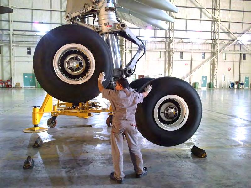
4 Big
5 Small
6 Hard Core
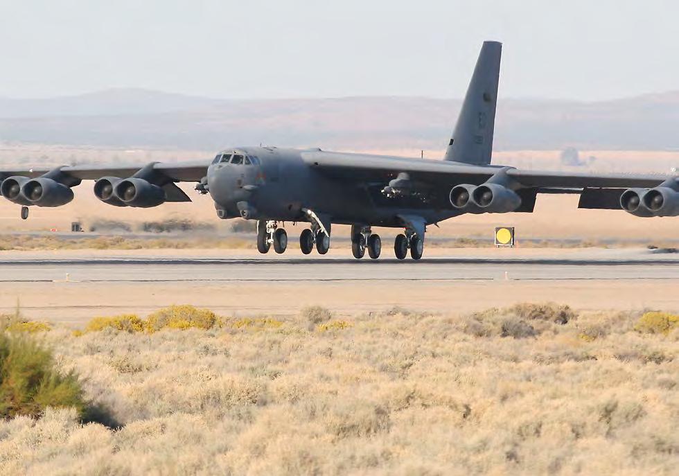
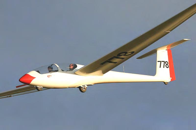
7 Landing Gear Arrangement Tail Wheel/Tail Dragger/Conventional Tricycle Tandem v Gliders or Military Floats v Amphibious Skis v Retractable Amphibious seaplane/flying boat Fixed or retractable
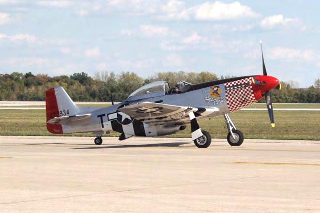
8 Tail Dragger/Conventional

9 Amphibious Tail Dragger

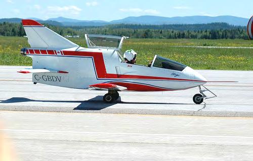
10 Tricycle Gear

11 Tricycle Gear
12 Tandem
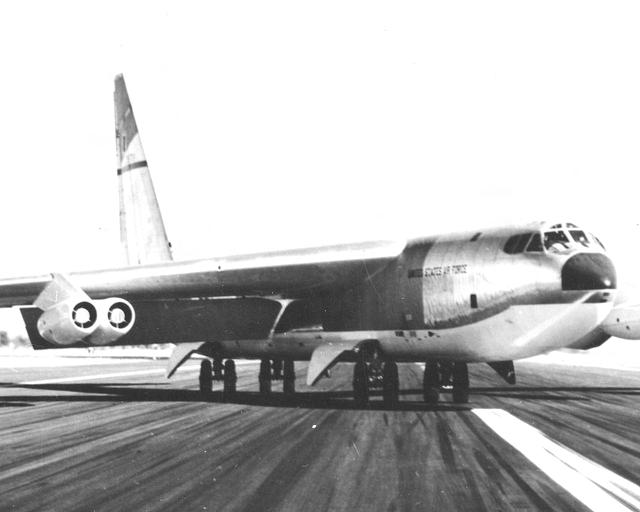
13 Tandem
14 Tandem
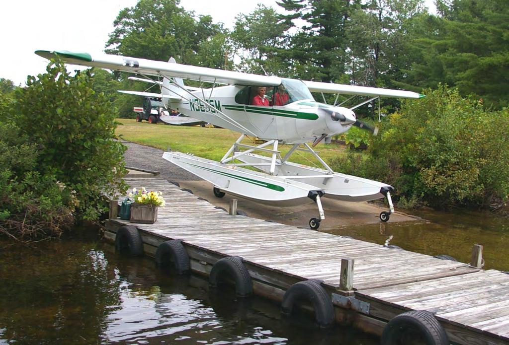
15 Floats (Amphibious)
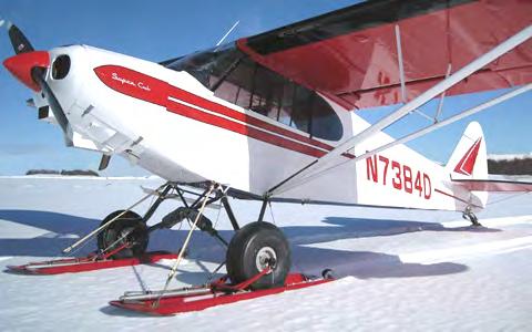
16 Skis
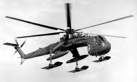
17 Skis

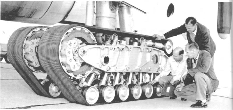
18 Skids

19 Skids (Wrong Kind)

20 Landing Gear Diagram
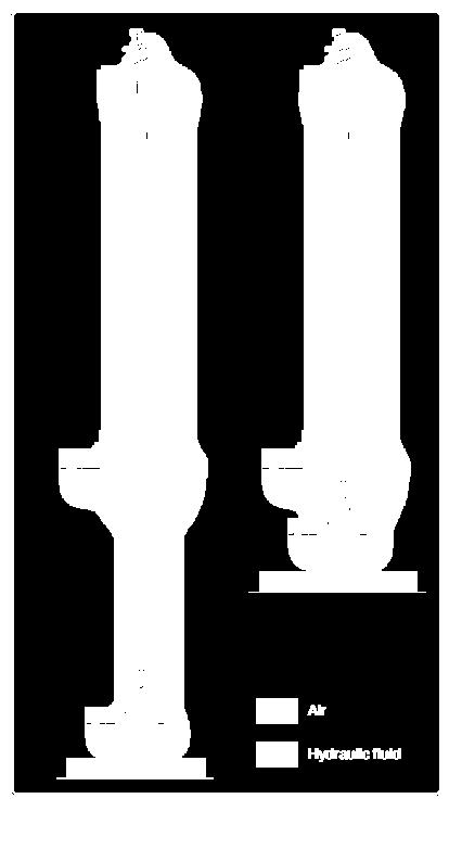
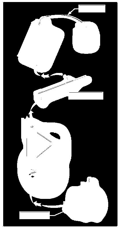
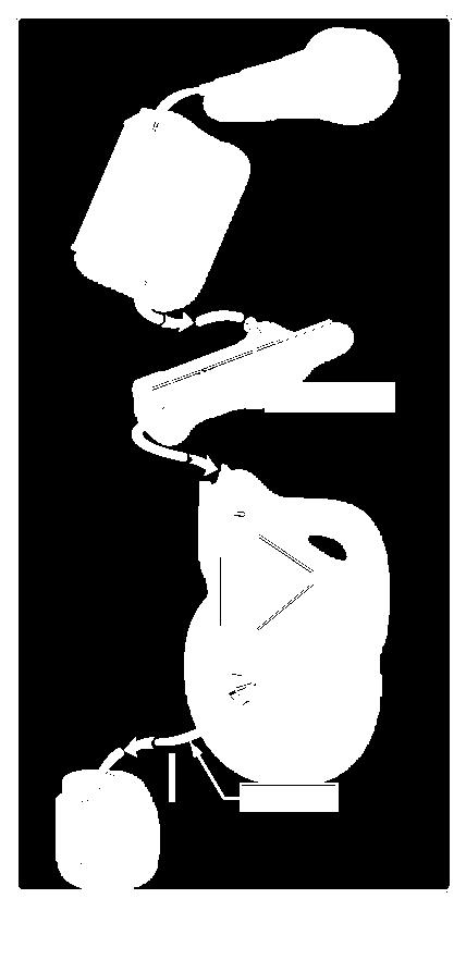
21 Shock Absorbing Leaf-Type Spring v Gear flexes Rigid Steel, aluminum or composites v Usually helicopters Bungee cords v Older tube/fabric type aircraft Solid, donut-type rubber Shock struts v Called oleo struts v Combination of hydraulic and gas shock absorbers

22 Leaf-Type Spring

23 Bungee Cord

24 Bungee Cord

25 Rubber Donut

26 Shock Struts

27 Shock Struts

28 Shock Trailing Arm

29 Shock Strut

30 Shock Strut

31 Shock Strut

32 Metering Tube Strut
33 Strut
34 Strut
35 Servicing Shock Strut Check normal operation v Check height v Check rebound action Look for leaks Jack-up aircraft Inspect for physical damage and leaks Release pressure v If possible, remove valve core after releasing pressure v Valves marked with a H are high pressure valves, be careful
36 Servicing Shock Strut If the strut must be rebuilt, take care not scratch Fill/replace hydraulic fluid per instructions Install new valve core (they are inexpensive) and slowly pressurize v Nitrogen is preferable v Pressurization level may be defined by PSI or extension of strut
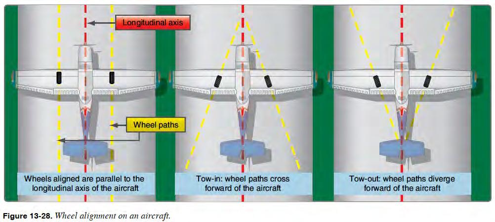
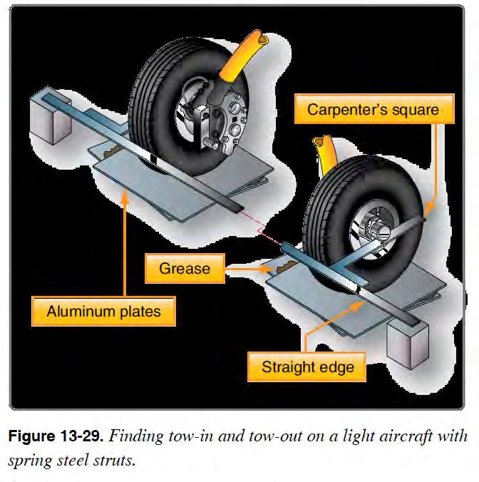
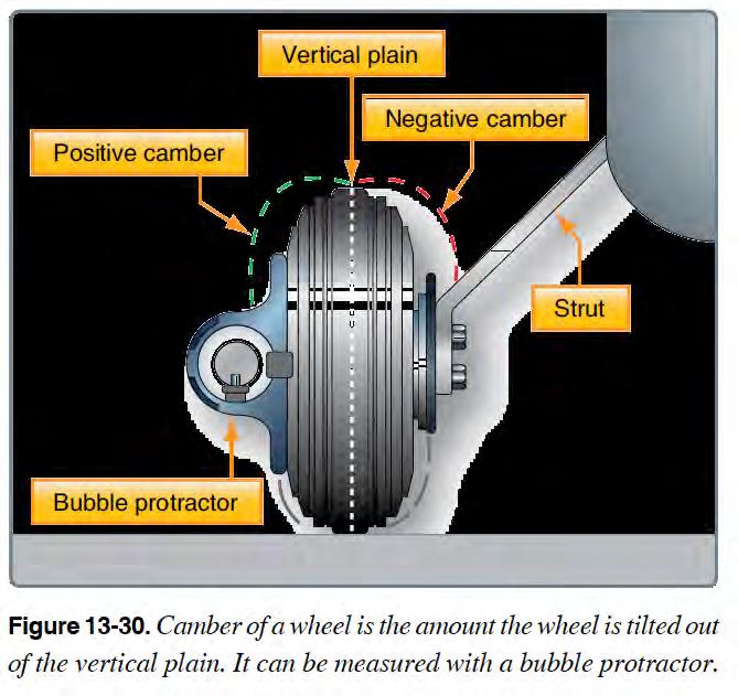
37 Alignment Toe-in/Toe-out is a measurement along the longitudinal axis (center line) v Toe-in front of tire points toward fuselage v Toe-out front of tire points away from fuselage v Corrected by inserting, removing, or changing the location of washers or spacers at the center pivotal point of the scissor torque links. Camber is the alignment along the vertical axis (up and down)
38 Alignment
39 Alignment

40 Alignment
41 Video 1 Video 2 Video 3 Video 4 Retract Testing
42 Retraction Systems Small aircraft v Mechanical v All electric v Combined electric and hydraulic Large aircraft v Power pack combination of electric motor and hydraulic pump v Usually hydraulic Usually engine driven v Sequence valve to control order of opening and closing v Orifice check valve will help slow down lowering of landing gear
43 Emergency Extension If the retraction fails or losses power, the system should fail in the extended position Gravity/free fall v Unlock the gear and it falls/locks into place Hand crank or pump Backup hydraulic system v Redundant pump v Backup electric pump v Ram air driven pump Compressed air
44 Landing Gear Components Position selector switch up is up and down is down Landing gear indicator lights v Green is down & locked v Controlled by position switches Warn system will alert the pilot when the throttle is retarted and the gear is still up Squat switch detects when pressure is on gear v Used to prevent retraction on the ground v Controls automatic brake application and engine reversers v Controls airframe timers
45 Landing Gear Maintenance Gear should be inspected and tested at each annual (100 hour inspection) v Clean v Check for wear and smooth action v Check light and indicators v Lubricate v Check doors, latches and braces v Check locks v Perform retract tests v Check emergency extension

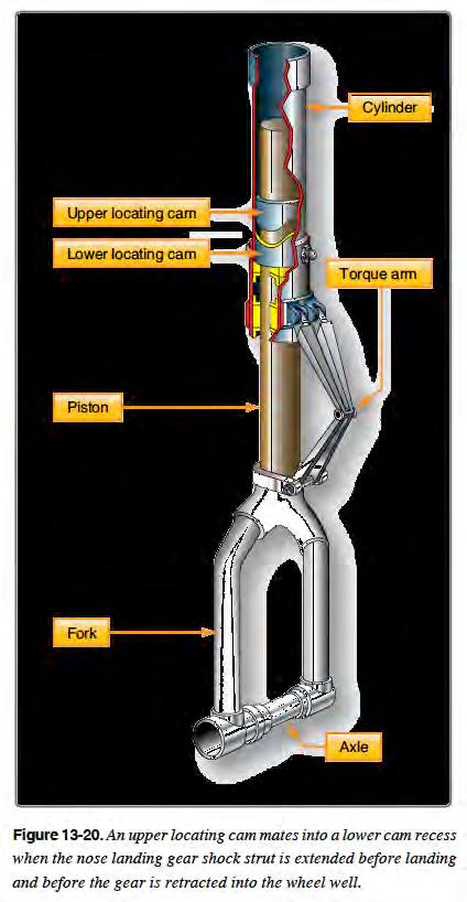
46 Nose Gear Steering
47 Nose Gear Steering Small Aircraft v Nose wheel driven by the rudder pedals Push rods Spring often used to provide give v Tail wheel driven by the rudder pedals Cable connected to tail wheel Tail wheel connected to rudder Springs often used to provide give v Free swiveling nose wheel Differential braking used to steer aircraft

48 Nose Gear Steering Large Aircraft v Hydraulically powered v Driven by rudder or separate wheel/tiller

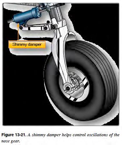
49 Shimmy Dampers
50 Shimmy Dampers Reduce nose wheel vibration (shimmy) Before rebuilding shimmy damper check for other causes of shimmy v Tire/wheel balance v Tire wear v Wheel bearings v Linkages Steering Dampers
51 Wheels
52 Wheels
53 Two piece Wheels Relieve pressure before splitting wheels v Precaution in case wheel bolts have been damaged Often tubeless Aluminum or magnesium v Inspect for damage such as cracks and corrosion Can be refinished/painted v High stressed wheel have regular scheduled NDT NDT Nondestructive Testing
54 Wheels High stress wheels use thermal plug v Melts when wheel gets to hot Prevents wheel from exploding v Prevent overheating with short ground rolls, slow taxi speeds, minimum braking, and proper tire inflation. v Wheel must be completing inspected after a thermal plug failure Tire should be replaced Wheel have white marks applied to both the wheel and tire v The marks are used to detect tire slippage v Service wheel/tire if slippage is detected

55 Thermal Plug


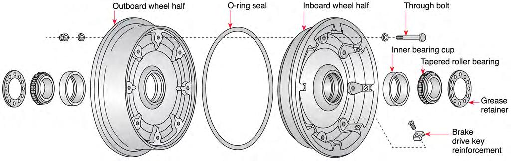
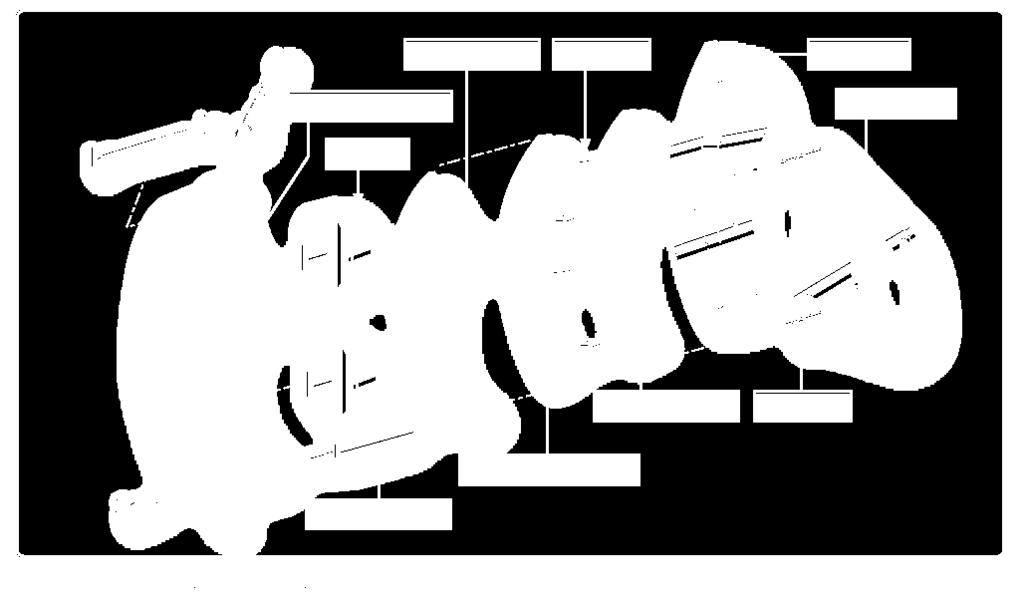
56 Wheel Bearings Bearing Cup/Race Bearing
57 Bearing Consist of the bearing and bearing cup v Bearing cup is also called the bearing race Bearing and cup are matched v Don t mix Bearing and cup have hardened metal surfaces v Any damage, replace v Replace both bearing and cup v Cup uses an interference fit Heat wheel to remove Heat wheel and refrigerate cup to insert
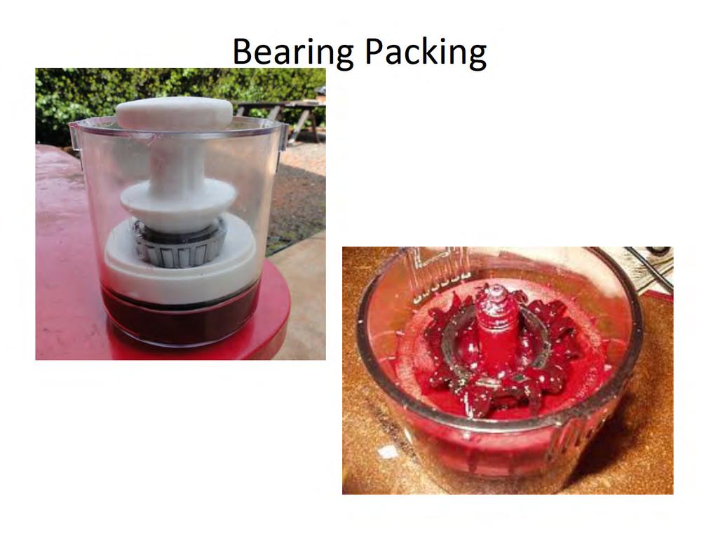
58 Bearing Bearing are packed with grease or packing v Lubricates bearing and keeps water/dirt out v Follow manufactures recommendation for grease used v Clean bearing and cup before packing Use mineral spirits and soft brush Dry before packing Don t spin bearing when dry Inspect regularly RTFM v Manufacturer often recommends a time interval Also consider calendar time v Every annual is recommended
59
60 Bearing Wheel held on by axle nut v Follow torque recommendation v Some procedures call for two step torquing v Insure axle nut is locked v Insure wheel turns freely

61 Floating Disk Brake

62 Floating Disk Brake

63 Fixed Disc

64 Fixed Disc Cleveland wheel showing the brake disk that bolts to the inner wheel half.

65 Fixed Disc

66 Multiple Disc

67 Multiple Disc

68 Expander Tube Brake
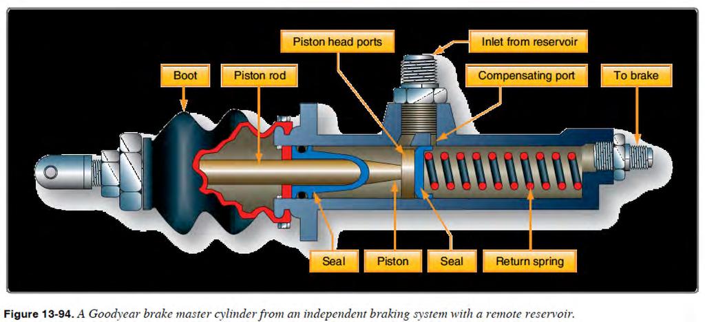
69 Brakes Floating single disc v Goodyear v Disc floats in wheel/caliper is fixed Fixed single disc v Cleveland v Disc is fixed to wheel/caliper floats Multiple disc v Large aircraft Expander tube obsolete v Must be hydraulic/can t be mechanical
70 Brakes Actuating System All modern brake systems are hydraulic Independent system all human powered Booster system use the aircraft s hydraulic system intermittently Power system completely powered by the aircraft s hydraulic system
71 Independent Master Cylinder


72 Remote Reservoir
73 Hydraulically Link
74 Hydraulically Link
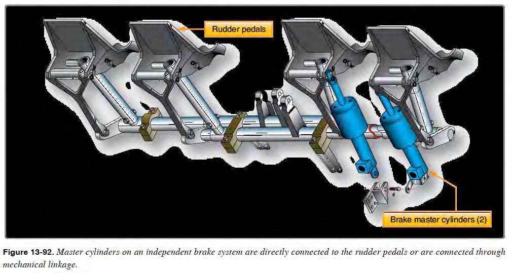
75 Independent Master Cylinder Pilot pushes on the top of the rudder pedal, which pushes on the master cylinder v Left and right wheels are independent Master cylinder creates pressure that is sent to the calibers which squeezes the brake pads against the brake disc Reservoirs v Stores extra hydraulic fluid v Built-in part of the master cylinder v Remote Container separate from the master cylinder
76 Independent Master Cylinder Compensating port permits the fluid to flow toward or away from the reservoir as temperature changes v Fluid comes from/goes to reservoir v Helps compensate for fluid leaks
77 Independent Master Cylinder

78 Independent Master Cylinder
79 Large Aircraft Brakes Boosted brakes Part of the braking force comes from the pilot, part of the force comes from the hydraulic system
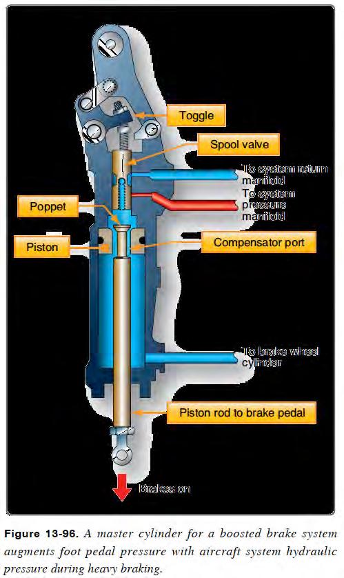
80 Boosted
81 Large Aircraft Brakes Power Brakes v All the braking power comes from the hydraulic system v Used because the aircraft is too large, too fast or the system requires too much hydraulic fluid for human power to supply v A brake control valve is used to convert the pilot s input to hydraulic pressure A special hydraulic valve that gradually controls pressure Also called a brake metering valve
82 Large Aircraft Brakes Power Brakes v Brake debooster valves/systems reduce the hydraulic pressure to a level more suited to braking systems Like a gear system, trades pressure for volume v Reduces pressure, increases volume Lower pressure helps increase release brakes more rapidly Lockout deboosters prevent main hydraulic and brake hydraulic fluids from mixing

83 Power Brake System
84 Brake Systems Emergency brake systems backup system to help in the event of a failure in the primary system v Shuttle valves are used to isolate emergency system from main system Parking brake are used to hold the aircraft in a stationary position v Physical lock brake pedal or use a valve to lock pressure in brakes v Don t apply when brakes are hot warps disks v Don t leave on for long periods of time
85 Brake Systems Anti-skid system prevents the tire from skidding while braking v Once a tire starts to skid, it loses traction v Skids can also damage the tires and cause blowouts v If the onset of a skid is detected, the brake pressure will be released Pressure release maybe accomplish by pulsing v Wheel speed sensors are used to detect wheel speed v A control unit determines if the wheel is slowing down too fast and releases brakes
86 Brake Systems Touchdown protection will prevent the application of brakes at the moment of touchdown v Wheels should be rolling before applying brakes v Landing gear squat switches are used to detect that the aircrafts weight is on the tires Auto brakes some large aircrafts will automatically apply brakes to reduce rolling distance v The level of braking can be selected by the pilot
87 Brake System Maintenance Lining measure minimum thickness v Rivet new linings to back plate Caliper maintenance v Check for cracks, corrosion, and leaks v Can be rebuilt Insure pistons and cylinders surfaces are clean and not scratched
88 Brake System Maintenance Master cylinder maintenance v Check for cracks, corrosion, and leaks v Can be rebuilt Insure pistons and cylinders surfaces are clean and not scratched v Broken spring can cause dragging of brakes Disk must be checked for physical damage and minimum thickness v Some disks can be turned to repair damage v Warped disks can cause chattering or squealing
89 Brake System Maintenance Fluid maintenance v Follow replacement schedule v Replace if contaminated v Bleeding the brakes must follow any opening of the hydraulic system Remove air from system System will feel spongy if air is in system v Firm brakes are an indication the air has been removed v Follow procedures exactly for anti-skid systems Check condition of brake lines v Old brake lines can flex and cause spongy brakes

90 Bleeding Brakes

91 Bleeding Brakes
92 Current Tire Types Type III type small aircraft v Designation A-B A - Tire width B Rim diameter e.g is 9 width with a 6 rim diameter v Low pressure Type VII high performance for jets v Designation A X B A Total diameter B Tire width e.g. 26 X 6.6 is 26 tall and 6.6 wide v High pressure
93 Current Tire Types Type VIII high performance for jets v Designation A X B - C A Total diameter B Tire width - - means bias ply, R means radial C Rim diameter e.g. 30 X 8.8 R 15 is 30 tall, 8.8 wide, radial, 15 rim v Prefixes B the tire has a 60 to 70 percent wheel rim to section width ratio with a bead taper of 15 degrees. H the tire has a 60 to 70 percent wheel rim to section width ratio with a bead taper of 5 degrees. v High pressure
94 Tires Ply Rating plies are reinforcing layers v Ply rating used to indicate the number of layers v Nowadays, ply rating is not an indication of tire layers Tube-type or tubeless both types are still used Bias ply or radial classification on how the construction plies are wrapped v Bias plies are 30 to 60 in relation to rotation v Radials are 90 v Both types are used Radial are usually used on high speed aircraft
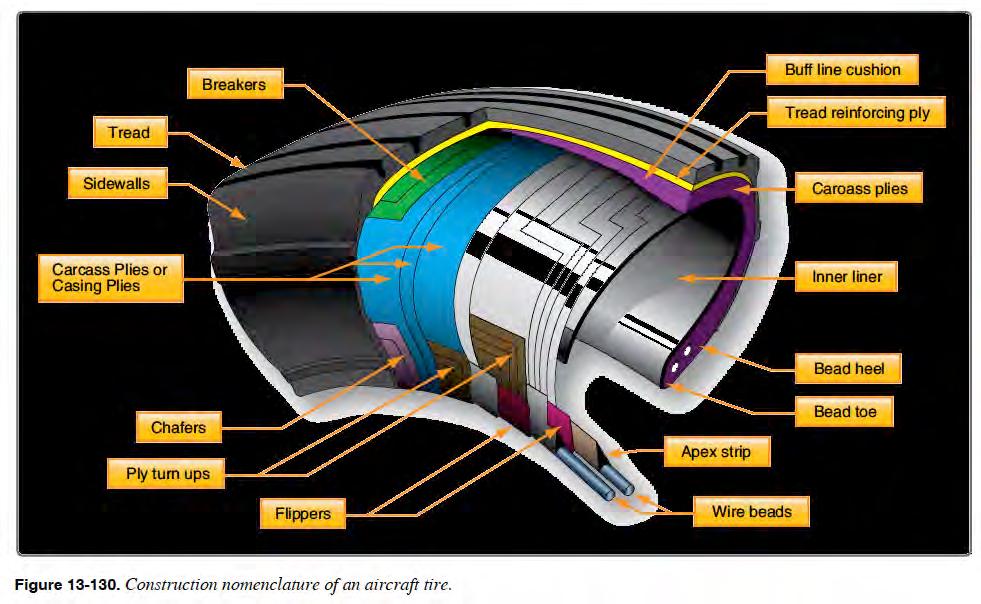
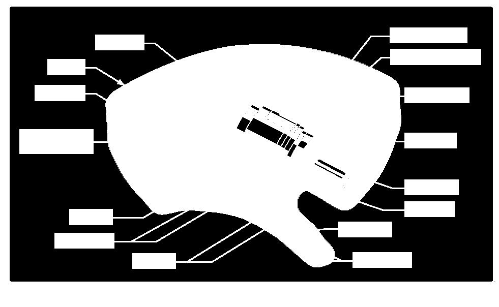
95 Tire Construction
96 Tire Construction Bead anchors tire to wheel Carcass plies forms the tire carcass and provides the tire s strength Tread crown to the tire, comes in contact with the ground Sidewalls outside rubber designed to protect carcass v Green or white dots mark seepage release vents on tubeless tires Must be kept clean

97 Tire Chine

98 Tire Chine

99 Tire Chine
100 Tire Inflation Proper inflation helps maintain tire life and operation Check inflation with a calibrated gauge Check a cold tire v Should be at ambient temperature v After landing, the tire should be allowed to cool down for 3 hours before checking inflation Pressure changes 1% for every 5 F v If going from hot airport to cold, inflate to maximum v If going from cold airport to hot, inflate to minimum
101 Tire Inflation Inflation should be check every week Inflation information comes from the aircraft maintenance manual not the tire manual If a multi-tire gear has more than 5 pounds inflation difference, the difference should be corrected and recorded in the logbook v The logbook entries will help track if there is a problem Over inflation can damage the wheel flange
102 Tire Wear vs. Inflation From AC B

103 Tire Wear vs. Inflation
104 Tire Condition Tread Depth Replacement v Worn to the bottom of a tread groove along more than 1/8 of circumference v If the first layer of ply is exposed for more than 1/8 of the circumference Uneven Wear v Determine cause and fix Flat spots may involve pilot training v Switching tires from side to side may help with wear For damage limits, consult manufacturer

105 Tire Removal
106 Tires Tire repair should be handled by a certified tire shop Tires can be retreaded an unlimited number of time if the carcass is not damaged Tire storage v Stack vertically v Keep away from ozone sources electric equipment v Wrap in dark plastic or paper v Keep away from UV light (sun), fuel, oil, hydraulic fluids and solvents v Keep away from extreme heat and cold
107 Tire Mounting Assemble wheel in tire v Light side of wheel halves should be opposite each other Light side is marked with an L, S/N or red dot v Lubricate wheel half O ring Use proper lubricate v Tire bead may require lubrication v Align heavy part of wheel with light part of tire Light part of tire has red mark Default heavy part of wheel is valve stem v Follow torque requirements v Video
108 Tire Mounting Inflate in a safety cage Nitrogen is used for inflation to minimize corrosion from moisture After inflation, leave unloaded for 12 hours v 5-10% pressure loss is normal due to tire stretching
109 Tube Tire Mounting Lightly inflate tube to give it shape before installing tire v Insure tube is wrinkle free Match heavy spot on tube with light spot on tire v Valve stem is default heavy spot Use tire talc inside tire and outside of tube Completely inflate tire, completely deflate and then inflate again v Helps tube seat properly
110 Tire Balancing Prevents heavy spots (land on the same spot) and vibrations Most tire balancing is done statically v The tire should not stop at the same place every time it is rotated
111 FAA Question An electric motor used to raise and lower a landing gear would most likely be a v a. shunt field series-wound motor. v b. split field shunt-wound motor. v c. split field series-wound motor. Answer: C
Aircraft Maintenance Prof. A.K Ghosh Prof. Vipul Mathur Department of Aerospace Engineering Indian Institute of Technology, Kanpur
 Aircraft Maintenance Prof. A.K Ghosh Prof. Vipul Mathur Department of Aerospace Engineering Indian Institute of Technology, Kanpur Lecture 05 Aircraft Landing Gear System Now, coming to the next aircraft
ABI WHEEL & BRAKE KIT
 INSTALLATION INSTRUCTIONS and INSTRUCTIONS FOR CONTINUED AIRWORTHINESS for the installation of ABI-199-62 WHEEL & BRAKE KIT for CESSNA AIRCRAFT SERIES 180, 185, 206 Doc No.: ABI-199-62-4 REV B 04/21/2017
Chapter. Tire, Wheel, and Wheel Bearing Fundamentals
 Chapter 74 Tire, Wheel, and Wheel Bearing Fundamentals Objectives After studying this chapter, you will be able to: Identify the parts of a tire and wheel assembly. Describe different methods of tire construction.
AV A IM V 103D Aircraft Wheels
 AVIM 103D Aircraft Wheels Aircraft Wheels Aircraft Wheels Usually two piece Two opposing conical tapered bearings for each wheel Can be tube type or tubeless Tubeless will have seal rings or sealing compound
INSTRUCTIONS CONTINUED AIRWORTHINESS
 INSTRUCTIONS FOR CONTINUED AIRWORTHINESS FOR GROVE MAIN WHEEL AND BRAKE ASSEMBLIES WITH FAA-TSO APPROVAL DOCUMENT 13046-11 Rev C April 29, 2018 TABLE OF CONTENTS SECTION PAGE Title Page... 1 Table of Contents...
TIRES AND WHEELS 22-1 TIRES AND WHEELS CONTENTS
 ZJ TIRES AND WHEELS 22-1 TIRES AND WHEELS CONTENTS TIRES... 1 WHEELS... 7 TIRES INDEX DESCRIPTION AND OPERATION RADIAL-PLY TIRES... 2 REPLACEMENT TIRES... 3 SPARE TIRE TEMPORARY... 2 TIRE INFLATION PRESSURES...
THE POCKET TIRE GUIDE FOR GENERAL AVIATION OPTIMUM AIRCRAFT TIRE CARE
 THE POCKET TIRE GUIDE FOR GENERAL AVIATION OPTIMUM AIRCRAFT TIRE CARE Keep this handy pocket guide as a quick reference on aircraft tires. Additional maintenance and operational guidelines can be found
Chapter 32 LANDING GEAR
 Chapter 32 LANDING GEAR 32-Title Page 1 January 23, 2012 INTENTIONALLY LEFT BLANK 32-Title Page 2 January 23, 2012 LIST OF EFFECTIVE PAGES Chapter Section Page Date 32 32-Title 1 January 23, 2012 2 January
Aircraft Suspension Systems
 AVIM 103D Aircraft Suspension Systems Suspension Systems Provide controlled flexibility to the landing gear systems while maintaining their structural integrity Up to a point they will eliminate the unusual
WHEELS BEARINGS TIRES
 GROUP 22 WHEELS BEARINGS TIRES CONTENTS Page GENERAL INFORMATION 1 SERVICE DIAGNOSIS 1 SERVICE PROCEDURES... 2 WHEELS... 2 Page BEARINGS 2 TIRES 4 SPECIFICATIONS AND TIGHTENING REFERENCE.. In Rear of Manual
Index for each Part of Tires
 Index for each Part of Tires 1. Tread NORMAL TREAD WEAR...57 UNEVEN TREAD WEAR (SHOULDER)... 58 UNEVEN TREAD WEAR (CENTER)... 59 IRREGULAR WEAR: ABRASION... 60 SPOT WEAR...61 TREAD RUBBER REVERSION...62
Tires with inner tubes were used until the 50s. Inner tube tires
 Tires Back in the day Way back in the day Pneumatic Tires Dunlop patented them for bicycles in 1888 Michelin put them on cars in 1895 Goodyear was started in 1898. Named after the inventor of vulcanized
Airframes Instructor Training Manual. Chapter 6 UNDERCARRIAGE
 Learning Objectives Airframes Instructor Training Manual Chapter 6 UNDERCARRIAGE 1. The purpose of this chapter is to discuss in more detail the last of the Four Major Components the Undercarriage (or
12. FRONT WHEEL/FRONT BRAKE/
 12 12 12-0 SERVICE INFORMATION... 12-1 FRONT BRAKE... 12-7 TROUBLESHOOTING... 12-2 FRONT SHOCK ABSORBER... 12-18 STEERING HANDLEBAR... 12-3 FRONT FORK... 12-21 FRONT WHEEL... 12-4 SERVICE INFORMATION GENERAL
SECTION 8 2 DO IT YOURSELF MAINTENANCE. Chassis
 DO IT YOURSELF MAINTENANCE Chassis SECTION 8 2 Checking the coolant level of the traction motor................ 184 Checking the radiator....................................... 185 Checking brake fluid........................................
Instructions for Continued Airworthiness
 Instructions for Continued Airworthiness for GROVE 28-4001 AND 28-4001A WHEEL AND BRAKE CONVERSION KITS in all PIPER AIRCRAFT INCLUDED IN THE FAA APPROVED MODEL LIST when installed In Accordance With Supplemental
TRUCK AND BUS TYRE I TECHNICAL MANUAL MAINTENANCE AND CARE
 TRUCK AND BUS TYRE I TECHNICAL MANUAL MAINTENANCE AND CARE About tyre inflation Truck alignment and tyre wear Tyre damage TECHNICAL INFORMATION MAINTENANCE AND CARE About tyre inflation ONE OF THE MOST
Modern Auto Tech Study Guide Chapters 71 & 73 Pages Brake Systems 49 Points. Automotive Service
 Modern Auto Tech Study Guide Chapters 71 & 73 Pages 1369 1444 Brake Systems 49 Points 1. Automotive systems use to stop, slow or to hold the wheels from turning. Brake, Friction Brake, Fraction Brake,
INSTRUCTIONS FOR CONTINUED AIRWORTHINESS
 INSTRUCTIONS FOR CONTINUED AIRWORTHINESS for GROVE MODEL 40-108 & 40-208 MAIN WHEELS DOCUMENT 12012-12 REV IR January 16, 2012 TABLE OF CONTENTS SECTION PAGE Title Page...1 Table of Contents...2 Record
AVIM 103D Landing Gear Notes Workbook
 AVIM 103D Landing Gear Notes Workbook 8/26/2010 Course Outline Landing gear Types Configurations Alignment Suspension systems Fixed gear Retractable Course Outline Retraction systems Steering systems Brakes
Tire & Wheel Fundamentals
 Tire & Wheel Fundamentals 1 Tire Function Provide traction (friction) with the road surface Provide cushion between the road and the metal wheel 2 Tire Construction Tube Tires Have a tube inside the tire
Brake System Diagnosis and Service
 AUMT 1310 - Brake System Diagnosis and Brake System Inspection Brake System Diagnosis and Donald Jones Brookhaven College Road test Hydraulic system Leaks Fluid condition Disc brakes Rotors and pads Drum
Tire 16 inch 225/75R inch 255/60R 18
 417009 133 1. SPECIFICATIONS Description Specification Tire 16 inch 225/75R 16 Tire inflation pressure 18 inch 255/60R 18 Front: 32 psi Rear: 32 psi (44 psi: when the vehicle is fully laden with luggage)
CHAPTER 9. AIRCRAFT SYSTEMS AND COMPONENTS
 CHAPTER 9. AIRCRAFT SYSTEMS AND COMPONENTS SECTION 1. INSPECTION AND MAINTENANCE OF LANDING GEAR 9-1. GENERAL. a. The landing gear on aircraft may be fixed or retractable. A fixed gear may be wheels, floats,
Energy Power and Transportation Final Exam
 Class: Date: Energy Power and Transportation Final Exam Multiple Choice Identify the choice that best completes the statement or answers the question. 1. Technician A says a 12-volt light bulb has a resistance
Unit HV04K Knowledge of Heavy Vehicle Chassis Units and Components
 Assessment Requirements Unit HV04K Knowledge of Heavy Vehicle Chassis Units and Components Content: Chassis layouts i. types of chassis ii. axle configurations iii. rear steered axles iv. self-steered
Chapter Thirteen. Nose Wheel Steering Systems. A. Small Aircraft. B. Large Aircraft. C. Shimmy Dampers
 Chapter Thirteen Nose Wheel Steering Systems A. Small Aircraft Almost all airplanes with tricycle landing gear have some provisions for steering on the ground by controlling the nose wheel. Some of the
BRAKE SYSTEM Return To Main Table of Contents
 BRAKE SYSTEM Return To Main Table of Contents GENERAL... 2 BRAKE PEDAL... 10 MASTER CYLINDER... 13 BRAKE BOOSTER... 16 BRAKE LINE... 18 PROPORTIONING VALVE... 19 FRONT DISC BRAKE... 20 REAR DRUM BRAKE...
Tyre Care & Safety for Agricultural Tires
 Tyre Care & Safety for Agricultural Tires Operating Instructions Some Points Worth Remembering; The BKT Agricultural tires are designed for Agricultural tractors, Trailers & Implements. Before using them
EMERGENCY GEAR DOWN HANDLE CHECK VALVE GEAR DROP TO EXTEND POSITION DOOR SELECTOR DOOR SELECTOR VALVE UPLOCK RELEASE CYLINDER DOOR CYLINDER
 WARN HORN CUT BEECHJET Landing Gear System LEGEND VENT LINE PRESSURE LINE RETURN LINE NITROGEN ELECTRICAL CIRCUIT CABLE LINE PACKAGE DUMP LANDING SELECTOR CHECK SELECTOR EMERGENCY DOWN HANDLE DROP TO EXTEND
Dura Force Disc Brake System Service Manual
 TS 20809_a 3501 Shotwell Drive ISO/TS 16949:2002 Registered (PH): 937.743.8125 Franklin, OH 45005 www.waltheremc.com (FX): 937.743.8232 Table of Contents General Description 1 3 Fastener Torque Chart 4
Brake Systems. Introduction
 Brake Systems Figure 1. A Typical Brake System Introduction The brake system (Figure 1) is designed to slow and halt the motion of a vehicle. To do that, various components within a hydraulic brake system
12. FRONT WHEEL/FRONT BRAKE/
 12 4.5kgm 0.9kg-m 4.5kg-m 12-0 SERVICE INFORMATION... 12-1 HYDRAULIC BRAKE... 12-10 TROUBLESHOOTING... 12-2 FRONT SHOCK ABSORBER... 12-16 FRONT WHEEL... 12-3 STEERING HANDLEBAR... 12-19 FRONT BRAKE...
INSTALLATION INSTRUCTIONS R1 REAR CONVERSION KIT
 INSTALLATION INSTRUCTIONS R1 REAR CONVERSION KIT INSTRUCTION FOR ASSEMBLY OF JEEP CJ SERIES W/AMC 20 REAR AXLES, 5 x 5-1/2" BOLT CIRCLE WITH A130-4 FULL FLOATING AXLE OR A130-5 (1 PIECE AXLE) Thank you
Tire 16 inch 225/75R inch 255/60R 18
 417009 143 1. SPECIFICATIONS Description Specification Tire 16 inch 225/75R 16 Tire inflation pressure 18 inch 255/60R 18 Front: 32 psi Rear: 32 psi (44 psi: when the vehicle is fully laden with luggage)
SUSPENSION 2-1 SUSPENSION TABLE OF CONTENTS
 DN SUSPENSION 2-1 SUSPENSION TABLE OF CONTENTS page ALIGNMENT... 1 FRONT SUSPENSION - 4x2... 6 page FRONT SUSPENSION - 4x4... 14 REAR SUSPENSION... 23 ALIGNMENT TABLE OF CONTENTS page AND OPERATION WHEEL
SUSPENSION 2-1 SUSPENSION CONTENTS
 DN SUSPENSION 2-1 SUSPENSION CONTENTS page ALIGNMENT... 1 FRONT SUSPENSION... 5 page REAR SUSPENSION... 13 ALIGNMENT INDEX page GENERAL INFORMATION WHEEL ALIGNMENT... 1 DIAGNOSIS AND TESTING PRE-ALIGNMENT
To study about various types of braking system.
 To study about various types of braking system INTRODUCTION The system is purely mechanical means & is independent of the hydraulic system which controls the brake normally. A brake commonly referred to
Revised BX-1000 BLACK MAX
 Revised 8-22-12 BX-1000 BLACK MAX PLEASE READ THROUGH THE ENTIRE MANUAL BEFORE INSTALLING YOUR BRAKE SYSTEM WARNING - DO NOT USE BRAKE FLUID - USE ATF HYDRAULIC FLUID ONLY **IMPORTANT** DO NOT USE ANY
"Figure 2: Trim Washer" was "Figure 1: Trim Washers". Page: 40A-06 REV 1: In Step 6, added "Fully torque the nut."
 14401 Keil Road NE, Aurora, Oregon, USA 97002 PHONE 503-678-6545 FAX 503-678-6560 www.vansaircraft.com info@vansaircraft.com Service Letters and Bulletins: www.vansaircraft.com/public/service.htm REVISION
INSTALLATION INSTRUCTIONS
 INSTALLATION INSTRUCTIONS REAR DISC CONVERSION KIT A128 1990-1995 JEEP WRANGLER (YJ) WITH DANA 35 AXLES (non-abs) Thank you for choosing STAINLESS STEEL BRAKES CORPORATION for your braking needs. Pleases
INSTALLATION INSTRUCTIONS
 INSTALLATION INSTRUCTIONS REAR DISC CONVERSION KIT A136-1 1976-86 AMC 20 AXLES WITH WARN FULL FLOATING AXLE CONVERSION Thank you for choosing STAINLESS STEEL BRAKES CORPORATION for your braking needs.
1999 Toyota RAV BRAKES Disc & Drum - Trucks & Vans
 DESCRIPTION & OPERATION 1999-2000 BRAKES Disc & Drum - Trucks & Vans WARNING: For warnings and procedures regarding vehicles equipped with Anti-Lock Brake Systems (ABS), see appropriate ANTI-LOCK article.
Welcome To Level 2 Training!
 Welcome To Level 2 Training! For aircraft tires to deliver maximized performance, reliability, durability, and safety, they must be properly cared for and serviced. The purpose of this training program
Steering and Suspension
 The Steering and Suspension system is engineered to allow the vehicle to turn and absorb road irregularities. The suspension is comprised of springs, suspension arms or links and shock dampers. These components
STEERING SYSTEM Introduction
 STEERING SYSTEM Introduction The steering makes it possible to change direction. The steering must be reliable and safe; there must not be too much play in the steering. It must be possible to steer accurately.
TIRES AND WHEELS 22-1 TIRES AND WHEELS CONTENTS
 PL TIRES AND WHEELS 22-1 TIRES AND WHEELS CONTENTS page page TIRES... 1 WHEELS... 8 TIRES INDEX page DESCRIPTION AND OPERATION RADIAL-PLY TIRES... 2 REPLACEMENT TIRES... 3 SPARE TIRE TEMPORARY... 2 TIRE
WHEELS 1. DESCRIPTION A.
 WHEELS 1. DESCRIPTION A. Main Wheels Serials 22-0002 thru 22-4045 before SB2X-32-21, 22T-0001 thru 22T-0689 before SB2X-32-21: The main wheels are of aluminum construction and designed to be used with
M-2300-T 6-Piston Mustang Brake Kit INSTALLATION INSTRUCTIONS
 Please visit www.fordracingparts.com for the most current instruction information!!! PLEASE READ ALL OF THE FOLLOWING INSTRUCTIONS CAREFULLY PRIOR TO INSTALLATION. AT ANY TIME YOU DO NOT UNDERSTAND THE
SECTION 7 2 DO IT YOURSELF MAINTENANCE MR2 U. Engine and Chassis
 SECTION 7 2 DO IT YOURSELF MAINTENANCE Engine and Chassis Checking the engine oil level................................. 168 Checking the engine coolant level............................ 169 Checking brake
Wheels Brakes Tires Hydraulic hoses/ fittings Landing Gear SPARE PART CATALOGUE. Price list EURO
 Wheels Brakes Tires Hydraulic hoses/ fittings Landing Gear SPARE PART CATALOGUE Price list EURO GENERAL MAINTENANCE AND INSTALLATION MANUAL The instructions detailes following are general instruction concerning
INSTALLATION INSTRUCTIONS
 INSTALLATION INSTRUCTIONS INSTALLATION INSTRUCTIONS FOR A136 REAR DRUM TO DISC BRAKE CONVERSION KIT for 1970-75 Jeep, CJ SERIES with Dana 44 flanged axle Thank you for choosing STAINLESS STEEL BRAKES CORPORATION
INSTALLATION INSTRUCTIONS
 INSTALLATION INSTRUCTIONS REAR DRUM TO DISC BRAKE CONVERSION KIT A118 pre-1985 Ford F150 (except 1983-1984 w/super H/D axle) Thank you for choosing STAINLESS STEEL BRAKES CORPORATION for your braking needs.
Part 7 DO IT YOURSELF MAINTENANCE
 Part 7 DO IT YOURSELF MAINTENANCE Chapter 7 2 Engine and Chassis Checking the engine oil level Checking the engine coolant level Checking brake fluid Checking power steering fluid Checking tire pressure
INSTALLATION INSTRUCTIONS
 INSTALLATION INSTRUCTIONS R1 REAR DRUM TO DISC BRAKE CONVERSION KIT A130-3 JEEP CJ SERIES W/AMC-20 REAR AXLES AND 5 x 5-1/2" BOLT CIRCLE Thank you for choosing STAINLESS STEEL BRAKES CORPORATION for your
SECTION 6 3 SERVICE PROCEDURES AND SPECIFICATIONS. Chassis
 SECTION 6 3 SERVICE PROCEDURES AND SPECIFICATIONS Chassis Specifications 206 Checking brake fluid 208 Checking power steering fluid 209 Checking tire pressure 210 Rotating tires 211 Checking and replacing
Modern Auto Tech Study Guide Chapter 65 & 66 Pages Tires, Wheels, Bearings 51 Points. Automotive Service. Danger of Old Tires!!
 Modern Auto Tech Study Guide Chapter 65 & 66 Pages 1241 1278 Tires, Wheels, Bearings 51 Points Automotive Service Danger of Old Tires!! Tires Manufactured Since 2000 Since 2000, the week and year the tire
Brake System H TX, H2.0TXS [B475]; H TX [B466] Safety Precautions Maintenance and Repair
![Brake System H TX, H2.0TXS [B475]; H TX [B466] Safety Precautions Maintenance and Repair](/thumbs/86/93834005.jpg "Brake System H TX, H2.0TXS [B475]; H TX [B466] Safety Precautions Maintenance and Repair") HMM180001 Brake System H1.5-1.8TX, H2.0TXS [B475]; H2.5-3.5TX [B466] Safety Precautions Maintenance and Repair When lifting parts or assemblies, make sure all slings, chains, or cables are correctly fastened,
HMM180001 Brake System H1.5-1.8TX, H2.0TXS [B475]; H2.5-3.5TX [B466] Safety Precautions Maintenance and Repair When lifting parts or assemblies, make sure all slings, chains, or cables are correctly fastened,
SECTION 35iS/U: LANDING GEAR & ENGINE MOUNT
 WD-1221 ENGINE MOUNT STANDOFF SECTION 35iS/U: LANDING GEAR & ENGINE MOUNT U-01203E-1 INBOARD DOUBLER PLATE U-01203B-1 INBOARD WEAR PLATE U-01203C-1 BEARING PLATE U-01203-2 (U-01203-1 SHOWN) INBOARD MAIN
I. Tire Care and Maintenance
 I. Tire Care and Maintenance 1. Purpose This manual forwards information relevant to maintenance and servicing of Bridgestone aircraft tires; new and retreaded. The practices and supporting information
Lucinda Handwriting & Arial Black 11, 16, 18 34
 Access and inspection holes are provided in the cabin floor for servicing cables, hydraulic lines, landing gear and gasoline tank. Additional access holes are provided on the exterior at the boom for servicing
INSTALLATION INSTRUCTIONS
 INSTALLATION INSTRUCTIONS PERFORMANCE AT THE WHEELS KITS W156-6 & W156-7 1965-74 MOPAR B & E BODY Thank you for choosing STAINLESS STEEL BRAKES CORPORATION for your braking needs. Pleases take the time
Handout Activity: HA511
 Using a tire pressure gauge Engines: Motive Power Types: Handout Activity: HA511 HA511-2 Student/Intern information: Name Date Class Using a tire pressure gauge Summary There are two main types of tire
INSTALLATION INSTRUCTIONS
 INSTALLATION INSTRUCTIONS FX4 ELITE REAR DISC CONVERSION KITS WITH INTERNAL PARKING BRAKE A110-14, A111-25, A111-29 for FORD 8" & 9" REAR ENDS Thank you for choosing STAINLESS STEEL BRAKES CORPORATION
Handout Activity: HA487
 Tires HA487-2 Handout Activity: HA487 Tires Tires are mainly made from synthetic materials. They can be tubed or tubeless, with different types of construction, profile and speed ratings. The tire provides
Wheels & Brakes. MATCO mfg. General Information for Wheel & Brake Assemblies. Technical Service Guide. Table of Contents SUBJECT PAGE
 MATCO mfg Wheels & Brakes General Information for Wheel & Brake Assemblies Table of Contents SUBJECT PAGE A. BRAKE LINING WEAR LIMITS--------------------- 3 B. SWIFTLINE PAD REPLACEMENT-----------------
SECTION 6 3 SERVICE PROCEDURES AND SPECIFICATIONS. Chassis
 SERVICE PROCEDURES AND SPECIFICATIONS Chassis SECTION 6 3 Specifications........................................... 208 Checking brake fluid...................................... 210 Checking power steering
INSTALLATION INSTRUCTIONS
 INSTALLATION INSTRUCTIONS PERFORMANCE AT THE WHEELS KIT W155-5 CHRYSLER 8 3 /4" & 9 3 /4" REAR AXLES Thank you for choosing STAINLESS STEEL BRAKES CORPORATION for your braking needs. Please take the time
SECTION 4A BRAKE SYSTEM TABLE OF CONTENTS
 SECTION 4A BRAKE SYSTEM TABLE OF CONTENTS Description and Operation... 4A-2 Braking System Testing... 4A-2 Hydraulic Brake System... 4A-2 Brake Pedal... 4A-2 Master Cylinder... 4A-2 Brake Booster... 4A-3
FRONT WHEEL AND BRAKE DISCS. Order Job/Part Q ty Remarks Removing the front wheel and brake discs NOTE:
 FRONT WHEEL AND BRAKE DISCS EAS00514 SIS FRONT WHEEL AND BRAKE DISCS 1 2 3 4 Order Job/Part Q ty Remarks Removing the front wheel and brake discs Remove the parts in the order listed. Place the motorcycle
DESCRIPTION & OPERATION
 DESCRIPTION & OPERATION BRAKE BOOSTER Delco-Moraine Single Diaphragm A combined vacuum-hydraulic unit which uses a combination of intake manifold vacuum and atmospheric pressure to provide power assist.
INSTALLATION INSTRUCTIONS PERFORMANCE AT THE WHEELS KIT W125
 INSTALLATION INSTRUCTIONS PERFORMANCE AT THE WHEELS KIT W125 1968-81 CAMARO & FIREBIRD 10 & 12 BOLT W/"C" CLIPS Thank you for choosing STAINLESS STEEL BRAKES CORPORATION for your braking needs. Pleases
CHASSIS CONTENTS EXTERIOR PARTS 7-1 FRONT WHEEL 7-2 FRONT BRAKE 7-6 HANDLEBARS 7-13 FRONT FORK 7-15 STEERING 7-23 REAR WHEEL 7-26 REAR BRAKE 7-30
 CHASSIS CONTENTS EXTERIOR PARTS 7- FRONT WHEEL 7-2 FRONT BRAKE 7-6 HANDLEBARS 7-3 FRONT FORK 7-5 STEERING 7-23 REAR WHEEL 7-26 REAR BRAKE 7-30 REAR SHOCK ABSORBER 7-32 SWING ARM 7-33 7 7- CHASSIS EXTERIOR
SUSPENSION 2-1 SUSPENSION CONTENTS
 ZJ SUSPENSION 2-1 SUSPENSION CONTENTS page ALIGNMENT... 1 FRONT SUSPENSION... 6 page REAR SUSPENSION... 14 ALIGNMENT INDEX page GENERAL INFORMATION WHEEL ALIGNMENT... 1 DIAGNOSIS AND TESTING SUSPENSION
STATEMENT OF CERTIFICATION COPYRIGHT 2014 DUNLOP AIRCRAFT TYRES LIMITED.
 Revision 5. February 017 Abbreviated Component Maintenance Manual Aircraft Tyres And Tubes STATEMENT OF CERTIFICATION The technical content of this ACMM is approved under the authority of Dunlop Aircraft
Service & Operation Manual. H619 Pulled Scraper
 Service & Operation Manual H619 Pulled Scraper Forward Humdinger Equipment LTD. is committed to your satisfaction with our products and services. Please review this manual and learn your product. This
INSTALLATION INSTRUCTIONS
 INSTALLATION INSTRUCTIONS PERFORMANCE AT THE WHEELS KIT W120-22, W120-23 1964 1/2-69 MUSTANG Thank you for choosing STAINLESS STEEL BRAKES CORPORATION for your braking needs. Pleases take the time to read
Arkansas Trucking Association Maintenance Council
 Arkansas Trucking Association Maintenance Council Tire Knowledge and Maintenance 1/29/2015 Larry Rambeaux, Sales and Service Engineer Purkeys Jack Henshall, Territory Service Manager Eaton Corporation
INSTALLATION INSTRUCTIONS
 INSTALLATION INSTRUCTIONS REAR DRUM TO DISC BRAKE CONVERSION KIT A130 JEEP CJ SERIES W/AMC-20 REAR AXLES AND 5 x 5-1/2" BOLT CIRCLE Thank you for choosing STAINLESS STEEL BRAKES CORPORATION for your braking
INSTALLATION INSTRUCTIONS
 INSTALLATION INSTRUCTIONS PERFORMANCE AT THE WHEELS KIT W125-42 GM 10 & 12 Bolt Rear Axles with Staggered or non-staggered Shocks with C-Clips Thank you for choosing STAINLESS STEEL BRAKES CORPORATION
TIRE BASICS GENERAL INFORMATION WHAT S INSIDE A TIRE TREAD BELTS BELT EDGE INSULATION BODY PLIES INNERLINER CASING BEAD SIDEWALL BEAD FILLER
 WHAT S INSIDE A TIRE BELTS TREAD BELT EDGE INSULATION BODY PLIES INNERLINER CASING BEAD SIDEWALL The tire s INNERLINER -- keeps air inside the tire. BEAD FILLER The CASING (or CARCASS) the internal substructure
MATCO mfg Wheels & Brakes
 MATCO mfg Wheels & Brakes MHE6B & MHE6B-SC External Caliper 6 E-Series Wheel and Brake Table of Contents Subject Page A Technical Information 2 B MHE6B & MHE6B-SC Parts List 3 D Brake Lining Wear Limits
Wheels. Wheels and Tires ! CAUTION. Wheel Selection
 Wheels Wheel Selection Wheels are a very important and critical component of your running gear system. When specifying or replacing your trailer wheels it is important that the wheels, tires, and axle
The Mooney s annual was due, and I decided, among
 nuts & bolts craft & technique Cheap Tires? Retreads may be the answer RICHARD KOEHLER The Mooney s annual was due, and I decided, among other things, to replace the tires, since replacement tires are
INSTALLATION INSTRUCTIONS
 INSTALLATION INSTRUCTIONS REAR DISC BRAKE CONVERSION KIT A126-1 1973-87 CHEVROLET 1/2 TON 2WD Thank you for choosing STAINLESS STEEL BRAKES CORPORATION for your braking needs. Pleases take the time to
TIRES AND WHEELS 22-1 TIRES AND WHEELS CONTENTS
 ZG TIRES AND WHEELS 22-1 TIRES AND WHEELS CONTENTS TIRES... 1 WHEELS... 7 TIRES INDEX DESCRIPTION AND OPERATION RADIAL-PLY TIRES... 2 REPLACEMENT TIRES... 3 SPARE TIRE (TEMPORARY)... 2 TIRE INFLATION PRESSURES...
INSTALLATION INSTRUCTIONS
 INSTALLATION INSTRUCTIONS FORCE 10 SPORT R1 REAR DISC CONVERSION KIT A126-50 2005-10 Chevrolet Silverado and GMC Sierra Thank you for choosing STAINLESS STEEL BRAKES CORPORATION for your braking needs.
INSTALLATION INSTRUCTIONS
 INSTALLATION INSTRUCTIONS REAR DISC BRAKE CONVERSION KIT A157 1991-2004 Dodge Dakota 2WD 1991-2002 Dodge Dakota 4WD 1998-2002 Dodge Durango Thank you for choosing STAINLESS STEEL BRAKES CORPORATION for
SR22 Airplane Flight Manual (AFM) Temporary Change
 Temporary Change") Cirrus Design TPOH AFM Temporary Change Airplane Flight Manual (AFM) Temporary Change Information in this Temporary Change adds to, supersedes, or deletes information in the basic Pilot s Operating Handbook.
Cirrus Design TPOH AFM Temporary Change Airplane Flight Manual (AFM) Temporary Change Information in this Temporary Change adds to, supersedes, or deletes information in the basic Pilot s Operating Handbook.
Clutches for Automobiles and Light Trucks
 Clutches for Automobiles and Light Trucks What does the Clutch do? Connects the engine torque to transmission when ENGAGED Unhooks engine from transmission when DISENGAGED Where is the driver s foot when
TH!NK neighbor Section 2 Chassis Section 2 Chassis
 General Specifications... 2 Torque Specifications... 2 Description and Operation... 4 Wheel Alignment Angles... 4 Brakes... 4 Diagnosis and Testing... 6 Ball Joint Inspection... 6 Wheel Bearing Inspection...
-GROUP 22 CONTENTS' WHEELS-BEARINGS-TIRES
 -GROUP 22 WHEELS-BEARINGS-TIRES CONTENTS' Page BEARINGS (FRONT WHEEL) 6 Removal (Without Disc Brakes) 6 Removal (With Disc Brakes) 6 Cleaning and Inspection... 6 Lubrication 6 Installation (Without Disc
INSTALLATION INSTRUCTIONS
 INSTALLATION INSTRUCTIONS BIG ROTOR / CALIPER RELOCATION REAR KIT SUM-BK1423 1999-2009 GM 1/2 Ton Trucks & SUVs Thank you for choosing SUMMIT RACING for your braking needs. Pleases take the time to read
INSTALLATION INSTRUCTIONS
 INSTALLATION INSTRUCTIONS DISC BRAKE CONVERSION KITS A121-1, A121-2, A121-3, A121-4 1967-69 Ford & Mercury Thank you for choosing STAINLESS STEEL BRAKES CORPORATION for your braking needs. Pleases take
Class 5 to 7 Truck and Bus Hydraulic Brake System
 Class 5 to 7 Truck and Bus Hydraulic Brake System Diagnostic Guide 2nd Edition www.bosch.us Important Service tes The information in this publication was current at the time of printing. The information
CHAPTER 9. AIRCRAFT SYSTEMS AND COMPONENTS
 9/27/01 AC 43.13-1B CHG 1 CHAPTER 9. AIRCRAFT SYSTEMS AND COMPONENTS SECTION 1. INSPECTION AND MAINTENANCE OF LANDING GEAR 9-1. GENERAL. a. The landing gear on aircraft may be fixed or retractable. A fixed
Rotate tires according to manufacturer's recommendations. (P-1) Reinstall wheel; torque lug nuts. (P-1)
 Reinstall wheel; torque lug nuts. (P-1)") JOB SHEET 8 Rotating Tires Name: Station: Date: NATEF Correlation This Job Sheet addresses the following NATEF task(s): 4.F.3 4.F.8 Rotate tires according to manufacturer's recommendations. (P-1) Reinstall
JOB SHEET 8 Rotating Tires Name: Station: Date: NATEF Correlation This Job Sheet addresses the following NATEF task(s): 4.F.3 4.F.8 Rotate tires according to manufacturer's recommendations. (P-1) Reinstall
Hydraulic System (i.e. Brakes & Cowl Flaps)
") Hydraulic System (i.e. Brakes & Cowl Flaps) B-17 Technical Session for Flight Engineers 7/8/2017 (with post meeting revisions 7/9/2017) The B-17G (specifically our Texas Raiders, TR) has a hydraulic system
Hydraulic System (i.e. Brakes & Cowl Flaps) B-17 Technical Session for Flight Engineers 7/8/2017 (with post meeting revisions 7/9/2017) The B-17G (specifically our Texas Raiders, TR) has a hydraulic system
Tyres OVERVIEW TYRE PRESSURES
 Tyres OVERVIEW Tyres of the correct type, manufacturer and dimensions, with correct cold inflation pressures are an integral part of every vehicle s design. Regular maintenance of tyres contributes not
INSTALLATION INSTRUCTIONS
 INSTALLATION INSTRUCTIONS BIG ROTOR / CALIPER RELOCATION FRONT KITS SUM-BK1422, BK1423, BK1424 1999-2006 GM 1/2 Ton Trucks & SUVs Thank you for choosing SUMMIT RACING for your braking needs. Pleases take