SAFETY INFORMATION...
|
|
|
- Merilyn Armstrong
- 6 years ago
- Views:
Transcription
1 TABLE OF CONTENTS INTRODUCTION to the VacFill SAFETY INFORMATION... 3 SYSTEM FEATURES & SPECIFICATIONS... 9 MACHINE OVERVIEW OPERATING PROCEDURES for VacFill OPERATING PROCEDURES for VacFill REPLACEMENT PARTS MAINTENANCE CUSTOMER SERVICE CONTACT INFO WARRANTY INFORMATION... 20
2 INTRODUCTION to the VacFill 3 Congratulations on the purchase of your VacFill 3 coolant service machine! The VacFill 3 is a device that removes and refills engine coolant quickly and efficiently. Before the coolant is refilled, a vacuum is applied to the cooling system to eliminate any air in the system. Suddenly, cooling system maintenance has become a more realistic proposition. Fluid exchanges are cleaner and neater than ever! Service neglect causes engine coolant to break down which can lead to the engine freezing or overheating. Historically, cooling system fluid service has been neglected, often due to the lack of a convenient method for providing such flush or fluid exchange services. Please take time to read through this manual to familiarize yourself with the VacFill 3 before performing your first coolant exchange. 2
3 IMPORTANT SAFETY NOTICE For your safety, read this manual thoroughly before operating this machine. Your VacFill 3 unit is intended for use by properly trained, skilled professional automotive technicians. The safety messages presented below and throughout this user s manual are reminders to the operator to exercise care when using this unit. Before using your VacFill 3 unit, always refer to and follow the safety messages and applicable service procedures provided by the manufacturer of the vehicle being serviced. Read All Safety Instructions Read, understand and follow all safety messages and instructions in this manual. Safety messages in this section of the manual contain a signal word with a three-part message and, in some instances, an icon. Signal Words The signal word indicates the level of the hazard in a situation: Indicates an imminently hazardous situation which, if not avoided, will result in death or serious injury to the operator or to bystanders. Indicates a potentially hazardous situation which, if not avoided, could result in death or serious injury to the operator or to bystanders. Indicates a potentially hazardous situation which, if not avoided, may result in moderate or minor injury to the operator or to bystanders. Indicates a situation which, if not avoided, may result in damage to the machine, or the vehicle being serviced. Safety Messages Safety messages in this section contain three different type styles: Normal type states the hazard. Bold type states how to avoid the hazard. Italic type states the possible consequences of not avoiding the hazard. 3
4 Safety Symbols A safety symbol, when present, gives a graphical description of the potential hazard, and how to avoid the hazard: Risk of Fire Read Instructions Before Use Risk of Explosion Mandatory Eye Protection Risk of Entanglement Mandatory Protective Gloves Dangerous Fumes Mandatory Protective Clothing Do Not Pull or Move Risk of Burns 4
5 IMPORTANT SAFETY INSTRUCTIONS Engine exhaust contains toxic gases. Vent vehicle s exhaust away from work area. Do not breathe exhaust. Exhaust gases will cause injury or death. Improper use and operation. Read, understand and follow all safety messages and operational procedures in this manual before operating this machine. This equipment should be operated only by qualified personnel. Use this equipment only as described in this manual. Improper use and operation of this product can result in injury. Engine systems can malfunction expelling fuel, oil vapors, hot steam, hot toxic exhaust gases and other flying particles. Wear safety goggles and protective clothing, user and bystander. Everyday eyeglasses only have impact resistant lenses, they are NOT safety glasses. Do not position head directly over or in front of carburetor or throttle body. Engine backfire can occur when air cleaner is out of normal position. Make sure gauge reads zero before connecting or disconnecting hose connections to adapters. Make sure cooling system pressure has been relieved before connecting or disconnecting hose connections and adapters. Keep a dry chemical (Class B) fire extinguisher rated for gasoline, chemical & electric fires in the work area. Fire, explosion, or flying particles may cause serious injury. Risk of expelling pressurized fluids. Wear safety goggles and protective clothing, user and bystander. 5
6 Engine systems can malfunction, expelling fuel, oil vapors, hot steam, hot toxic exhaust gases and other debris. Always unplug the machine from its power source when not in use. Keep the service hoses away from hot or moving engine parts. Hoses can split or burst causing fluid to be expelled. Avoid contact with engine coolant. Treatment methods are as follows: Eyes: Flush eyes with plenty of water. Skin: Wash with soap and water. Inhalation: Move to uncontaminated area. Ingestion: If large amount, get medical attention. If any irritation persists, get medical attention. Dispose of waste fluid according to environmental laws and regulations. Fuel, oil vapors, hot steam, hot toxic exhaust gases, pressurized fluid, and other debris can cause serious injury. Risk of unexpected vehicle movement. Block drive wheels before starting vehicle s engine to begin an exchange. Unless instructed otherwise, set parking brake and put gear selector in park. Do not leave a running vehicle unattended. If vehicle has an automatic parking brake release, disconnect release mechanism for testing and reconnect when testing is completed. A moving vehicle can cause injury. Risk of entanglement. Engine has moving parts. Do not place tools on fenders or other places in engine compartment. Keep yourself, clothing, battery cables and service hoses clear of moving parts such as fan blades, belts, pulleys, hood and doors. Barriers are recommended to help identify danger zones in test area. Prevent personnel from walking through immediate test area. Contact with moving parts can cause injury. Risk of fire or explosion. Do not operate in the vicinity of open containers of flammable liquids such as gasoline. Keep hoses and jumper cables away from heat sources and sharp edges. Do not operate equipment with damaged cords or hoses until they have been examined by a qualified serviceman. Fire or explosion can cause injury. 6
7 Risk of fire or explosion. Gases produced by a battery are highly explosive. Wear safety goggles and protective clothing, user and bystander. This machine is equipped to operate on 12-volt DC power only. A power source greater than this can result in serious injury to the user as well as damage to the machine. Do not smoke, place metal tools on battery or allow a spark or flame in vicinity of battery. Clean battery terminals before hooking the machine s battery clips to them. During cleaning, keep airborne corrosion from eyes, nose and mouth. Be sure both battery cables are tightly connected to the battery terminals as instructed before proceeding with a fluid exchange. Never remove battery cables from the battery terminals while the machine is operating. Battery explosion can cause injury. Risk of burns. Wear gloves when handling hot engine components. Do not remove radiator cap unless engine is cold. Pressurized engine coolant may be hot. Do not touch hot exhaust systems, manifolds, engines, radiators, etc. Hot fluid and engine parts may cause injury. Battery acid is a highly corrosive sulfuric acid. Wear safety goggles and protective gloves, user and bystander. Have plenty of fresh water and soap nearby. If battery acid contacts skin, clothing, or eyes, flush exposed area with soap and water for 10 minutes. While cleaning battery s terminals, keep airborne corrosion from eyes, nose and mouth. Do not touch eyes while working near battery. Battery acid can burn eyes and skin. Risk of burns. Wear gloves when working near hot engine components. Do not touch hot exhaust systems, manifolds, engines, radiators, etc. The fluid coming from the vehicle along with some of the machine s components that the fluid comes into direct contact with (i.e. hoses and fittings) may reach temperatures uncomfortable to the touch. Exercise caution in avoiding contact with these items. Hot components can cause injury or discomfort. 7
8 Risk of injury. This equipment should be operated by qualified personnel only. Use this equipment only as described in this manual. Always unplug the machine from its power source when not in use. Loop the power cord loosely in its proper location when machine is not in use. Do not operate equipment with a damaged battery cables or hoses, or if the equipment has been dropped or damaged, until it has been examined by a qualified service representative. Care should be taken to arrange the battery cables and service hoses so that they will not be tripped over or pulled. Never pull on the power cables or service hoses to transport the machine. Damage may occur to these components, or machine may tip over. Keep area of operation clear of unnecessary tools and equipment. Utilize recessed tool storage areas on the top of the machine. Never leave the machine running unattended. The VacFill 3 is not designed for any other purpose than the servicing of automotive cooling systems. Operation of this machine by anyone other than qualified personnel may result in injury. Misdiagnosis may lead to incorrect or improper repair and/or adjustment. Do not rely on erratic, questionable, or obviously erroneous test information or results. If test information or results are erratic, questionable, or obviously erroneous, make sure that all connections and data entry information are correct and that the test procedure was performed correctly. If test information or results are still suspicious, do not use them for diagnosis. Improper repair and/or adjustment may cause vehicle or equipment damage or unsafe operation. Risk of equipment damage. Connect battery cables to a 12-volt power source only (i.e. vehicle s battery). Servicing, transporting, or storing this machine in an attitude other than the normal operating position can result in fluid spillage and/or component damage. Never pull on the power cables or service hoses to transport the unit. Damage may occur to these components, or machine may tip over. Always use the handle to move. Periodically clean the machine by wiping down with a clean, soft, dry cloth. Improper operation of equipment may result in damage to machine or components. SAVE AND FOLLOW THESE INSTRUCTIONS! 8
9 DIMENSIONS & TECHNICAL SPECIFICATIONS DIMENSIONS: 52" Tall (VacFill 3 ) 23" Wide 27" Deep Service Hose: 10 outside of machine Wheels: 5 locking casters (front) 9 3/4 casters (back) Fluid Tanks: (2) 28-Quart New Fluid Tanks 28-Quart Waste Fluid Tank Weight: 160 lbs (VacFill 3 ) 170 lbs (VacFill 3 +) TECHNICAL SPECIFICATIONS: Power: 115 psi Shop Air 12-Volt DC from vehicle battery (VacFill 3 +) Operating Temperature: 60º to 110ºF (15º to 43ºC) FEATURES Durable roto-cast polyethylene body and tanks prevent vehicle damage Ergonomically correct working height 5 locking front caster wheels & 10 rear wheels allow easy maneuverability Clear service hose allows visual confirmation of new and waste fluid movement Easy access service panel 9
10 MACHINE OVERVIEW (VacFill 3 + Shown) 10
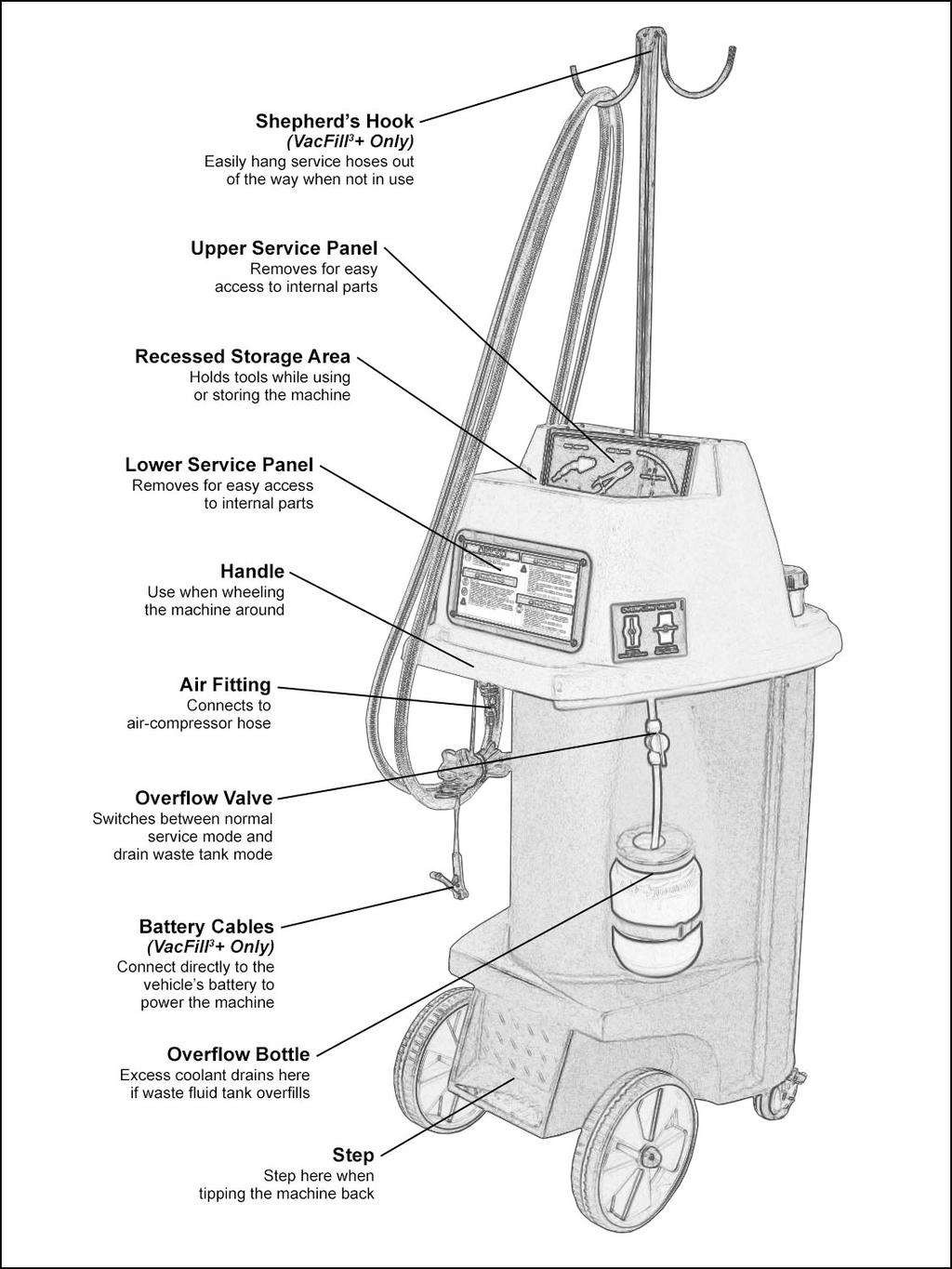
11 11


12 MACHINE CONTROLS OVERVIEW Please take time to familiarize yourself with the VacFill 3 controls before performing your first coolant exchange. The Main Control Panel is located on the front of the machine. VacFill3 Coolant Service Machine VacFill3+ Coolant Service Machine w/ Top-Off Feature Overflow Valve Located on the left rear of the machine 12
13 OPERATING PROCEDURES for VacFill 3 IMPORTANT: Machine needs at least 115psi of air to operate. SUCTION WAND PROCEDURE: 1. Connect Wand Adapter to service line & open Ball Valve. 2. Turn Overflow Valve on back of machine to Normal Service Position. 3. Turn Right Dial to Vacuum/Drain Waste position. 4. Turn Left Dial to Air On position to start. 5. Turn Left Dial to Air Off position when finished. REMOVE & FILL PROCEDURE: 1. Make sure vehicle is turned off, but at operating temperature. 2. Turn Overflow Valve on back of machine to Normal Service Position. 3. Connect Wand Adapter to service hose, open Ball Valve, turn Left Dial to Air On position and Right Dial to Vacuum/Drain Waste position to remove waste fluid from overflow bottle. 4. When overflow bottle is empty, turn Left Dial to Air Off position. 5. Remove radiator cap. 6. Connect Cone Adapter to service line. 7. Turn Right Dial to Vacuum/Drain Waste position. 8. Turn Left Dial to Air On position. 9. Open Ball Valve on service hose. 10. Insert Cone Adapter into radiator, making sure the tip of the cone is submerged. HINT: If servicing from bottle, insert a hose into the cone long enough to reach near the bottom of the bottle (hose not supplied). 13
14 11. Wait until no more waste fluid is being removed. 12. Turn Right Dial to desired fluid type to fill the radiator making sure you don t break the vacuum seal between the rubber cone & the radiator. 13. Turn Left Dial to Air Off position after fluid is removed. 14. Wait until new fluid stops entering radiator & remove Cone Adapter. 15. Top off radiator if needed. 16. Refill overflow bottle & replace radiator cap. DRAIN TANKS PROCEDURE: DRAIN WASTE TANK 1. Turn Right Dial to Vacuum/Drain Waste position. 2. Attach Wand Adapter to service hose. 3. Turn Overflow Valve on back of machine to Drain Waste Tank Position. 4. Open Ball Valve on service hose and place into waste container. 5. Turn Left Dial to Air On position to drain waste tank. 6. When finished draining, remove service hose from waste container, and close Ball Valve. 7. Turn Left Dial to Air Off position. 8. Turn Overflow Valve on back of machine to Normal Service Position to release air pressure from waste fluid tank. NOTE: Coolant may splash out while air pressure is being released. Keep hands and face away from the overflow bottle. 14


15 OPERATING PROCEDURES for VacFill 3 + IMPORTANT: Machine needs at least 115psi of air to operate. SUCTION WAND PROCEDURE: 1. Connect Wand Adapter to Black Service Hose & open Ball Valve. 2. Turn Overflow Valve on back of machine to Normal Service Position. 3. Turn Right Dial to Vacuum/Drain Waste position. 4. Flip Switch to Air On position to start. 5. Flip Switch to Off position when finished. REMOVE & FILL PROCEDURE: 1. Make sure vehicle is turned off, but at operating temperature. 2. Turn Overflow Valve on back of machine to Normal Service Position. 3. Connect Wand Adapter to Black Service Hose, open Ball Valve, flip Switch to Air On position and Right Dial to Vacuum/Drain Waste position to remove waste fluid from overflow bottle. 4. When overflow bottle is empty, flip Switch to Off position. 5. Remove radiator cap. 6. Connect Cone Adapter to Black Service Hose. 7. Turn Right Dial to Vacuum/Drain Waste position. 8. Flip switch to Air On position. 9. Open Ball Valve on Black Service Hose. 15
. 11. Wait until no more waste fluid is being removed. 12.")
16 10. Insert Cone Adapter into radiator, making sure the tip of the cone is submerged. HINT: If servicing from bottle, insert a hose into the cone long enough to reach near the bottom of the bottle (hose not supplied). 11. Wait until no more waste fluid is being removed. 12. Turn Right Dial to desired fluid type to fill the radiator making sure you don t break the vacuum seal between the rubber cone & the radiator. 13. Flip switch to Off position after fluid is removed. 14. Wait until new fluid stops entering radiator & remove Cone Adapter. 15. Top off radiator if needed (see Top-off Procedure ). 16. Refill overflow bottle & replace radiator cap. TOP-OFF PROCEDURE: 1. Connect Wand Adapter to Red Service Hose. 2. Make sure Ball Valve is closed. 3. Turn Left Dial to desired fluid type. 4. Flip Switch to Pump On position. 5. Open Ball Valve at the end of the Red Service Hose to regulate fluid flow. 6. Flip Left Dial and Switch to Off position when finished. DRAIN TANKS PROCEDURE: DRAIN WASTE TANK 1. Turn Right Dial to Vacuum/Drain Waste position. 2. Attach Wand Adapter to Black Service Hose. 3. Turn Overflow Valve on back of machine to Drain Waste Tank Position. 4. Open Ball Valve on Black Service Hose and place into waste container. 5. Flip Switch to Air On position to drain waste tank. 6. When finished draining, remove Service Hose from waste container, and close Ball Valve. 7. Flip Switch to Off position. 8. Turn Overflow Valve on back of machine to Normal Service Position to release air pressure from waste fluid tank. NOTE: Coolant may splash out while air pressure is being released. Keep hands and face away from the overflow bottle. 16
17 REPLACEMENT PARTS LIST Part # Description W Control Panel w/ Label (VacFill3) Control Panel w/ Label (VacFill3+) Wire Harness (VacFill3+) Fluid Pump (VacFill3+) Vacuum Gauge Upper Service Panel w/ Equipment List Label R Lower Service Panel w/ Warning Sticker R Measure Strip Label Vinyl Mat (Small Front) Vinyl Mat (Large Rear) Way Ball Valve Way Ball Valve Vacuum Generator Internal Hose Kit (VacFill3) Internal Hose Kit (VacFill3+) Black Service Hose Red Service Hose (VacFill3+) Black Plastic Body Red Plastic Top Waste Fluid / Air Tank (Steel) White Plastic Tank (L) White Plastic Tank (R) Overflow Bottle Overflow Valve Velcro Strap for Overflow Bottle Tank Cap R Locking Caster Wheel Wheel P Shepherd's Hook Wand Adapter Cone Adapter Assembly Small Hose Clamp Pliers Medium Hose Clamp Pliers Large Hose Clamp Pliers Green Fluid Tank Label Red Fluid Tank Label W Battery Cable Assembly Operations Manual 17
18 To order replacement parts for the VacFill 3, call:
19 MAINTENANCE To keep your machine working properly Keep debris out of new fluid tanks. Avoid spilling fluid on the control panel. Periodically wipe down exterior using a soft, damp cloth. CUSTOMER SERVICE CONTACT INFORMATION If you are experiencing problems with this machine, call technical support at:
20 LIMITED ONE (1) YEAR WARRANTY Flo-Dynamics warrants only to the original Purchaser that under normal use, care and service, the Equipment (except as otherwise provided herein) shall be free from defects in material and workmanship for one year from the date of original invoice. External hoses, remote control modules, adapters and all other attachments, supplies and consumables (except as otherwise provided herein) are warranted for 90 calendar days from the date of original invoice. Filter elements are not warranted. Printed circuit boards purchased from, but not installed by Seller are not warranted. SELLER S OBLIGATIONS UNDER THIS WARRANTY ARE LIMITED SOLELY TO THE REPAIR OR, AT SELLER S OPTION, REPLACEMENT OF EQUIPMENT OR PARTS WHICH TO SELLER S SATISFACTION ARE DETERMINED TO BE DEFECTIVE AND WHICH ARE NECESSARY, IN SELLER S JUDGEMENT, TO RETURN THE EQUIPMENT TO GOOD OPERATING CONDITION. NO OTHER WARRANTIES EXPRESS OR IMPLIED OR STATUTORY, INCLUDING WITHOUT LIMITATION ANY IMPLIED WARRANTY OF MERCHANTABILITY OR FITNESS FOR A PARTICULAR PURPOSE, SHALL APPLY AND ALL SUCH WARRANTIES ARE HEREBY EXPRESSLY DISCLAIMED. This warranty does not cover (and separate charges for parts, labor and related expenses shall apply to) any damage to, malfunctioning, inoperability or improper operation of the Equipment caused by, resulting from or attributable to (A) abuse, misuse or tampering; (B) alteration, modification or adjustment of the Equipment by anyone other than Seller s authorized representatives; (D) improper or negligent use, application, operation, care, cleaning, storage or handling; (E) fire, water, wind, lightning or other natural causes; (F) adverse environmental conditions, including, without limitation, excessive heat, moisture, corrosive elements, or dust or other air contaminants, radio frequency interference, electric power failure, power line voltages beyond those specified for the equipment, unusual physical, electrical or electromagnetic stress, and/or any other condition outside of Seller s environmental specifications; (G) use of the Equipment in combination or connection with other equipment, attachments, supplies or consumables not manufactured or supplied by Seller; or (H) failure to comply with any applicable federal, state or local regulation. Repairs or replacements qualifying under this Warranty will be performed on regular business days during Seller s normal working hours within a reasonable time following Purchaser s request. All requests for Warranty service must be made during the stated Warranty period. This warranty is non-transferable. 20
TABLE OF CONTENTS. INTRODUCTION to the BrakeMate Jr... 2 SAFETY INFORMATION... 3 SYSTEM FEATURES & SPECIFICATIONS... 9 MACHINE OVERVIEW...
 TABLE OF CONTENTS INTRODUCTION to the BrakeMate Jr.... 2 SAFETY INFORMATION... 3 SYSTEM FEATURES & SPECIFICATIONS... 9 MACHINE OVERVIEW... 10 MASTER CYLINDER ADAPTERS... 11 OPERATING INSTRUCTIONS...13
TABLE OF CONTENTS. INTRODUCTION to the PSI COOL... 2 SAFETY INFORMATION... 3 SYSTEM FEATURES & SPECIFICATIONS... 9 MACHINE OVERVIEW...
 TABLE OF CONTENTS INTRODUCTION to the PSI COOL... 2 SAFETY INFORMATION... 3 SYSTEM FEATURES & SPECIFICATIONS... 9 MACHINE OVERVIEW... 10 OPERATING INSTRUCTIONS... 11 REPLACEMENT PARTS... 15 MAINTENANCE
TABLE OF CONTENTS. INTRODUCTION to the PSX SAFETY INFORMATION... 3 SYSTEM FEATURES & SPECIFICATIONS... 9 MACHINE OVERVIEW...
 TABLE OF CONTENTS INTRODUCTION to the PSX3000... 2 SAFETY INFORMATION... 3 SYSTEM FEATURES & SPECIFICATIONS... 9 MACHINE OVERVIEW... 10 CONTROL PANEL OVERVIEW... 11 OPERATING PROCEDURE... 13 REPLACEMENT
TABLE OF CONTENTS. INTRODUCTION to the BrakeMate... 2 SAFETY INFORMATION... 3 SYSTEM FEATURES & SPECIFICATIONS... 9 MACHINE OVERVIEW...
 TABLE OF CONTENTS INTRODUCTION to the BrakeMate... 2 SAFETY INFORMATION... 3 SYSTEM FEATURES & SPECIFICATIONS... 9 MACHINE OVERVIEW... 10 OPERATING PROCEDURES... 13 MASTER CYLINDER ADAPTERS... 15 REPLACEMENT
EW23001 Power Steering Fluid Exchange Machine Operations Manual
 EW23001 Power Steering Fluid Exchange Machine Operations Manual 2018 ITW Professional Automotive Products Inc. All rights reserved 3606 Craftsman Blvd. Lakeland FL 33803 equipment.wynnsusa.com REV. 03
Table of Contents TABLE OF CONTENTS. INTRODUCTION to the TSD
 Flo-Dynamics TSD440 Table of Contents TABLE OF CONTENTS INTRODUCTION to the TSD440... 2 I. SAFETY INFORMATION... 3 - Section 1.01: Important Safety Notice... 3 - Section 1.02: Important Safety Instructions...
EBS PRODUCTS
 ! EBS Coolant Flush EBS PRODUCTS www.ebsproducts.com OPERATIONS MANUAL EC-1 Coolant Flush #1000-0070 1-1-16! 1 EBS Products Westminster, CA 92683 Phone: 877-955-0515 Fax: 714-896-6711 E-mail: sales@ebsproducts.com
TABLE OF CONTENTS. I. INTRODUCTION to the ADVANTAGE BRAKE PRO...2 II. SAFETY INFORMATION...3
 OPERATIONS MANUAL TABLE OF CONTENTS I. INTRODUCTION to the ADVANTAGE BRAKE PRO...2 II. SAFETY INFORMATION...3 - Section 1.01: Important Safety Notice...3 - Section 1.02: Important Safety Instructions...5
Important Safety Instructions
 SAVE THESE INSTRUCTIONS EAZ0042B04C Rev. C 2011 Snap-on Incorporated All rights reserved. ii For your own safety and the safety of others, and to prevent damage to the equipment and vehicles upon which
Table of Contents TABLE OF CONTENTS. INTRODUCTION to the TSD I. SAFETY INFORMATION... 3 II. SYSTEM FEATURES & SPECIFICATIONS...
 Flo-Dynamics TSD450 Table of Contents TABLE OF CONTENTS INTRODUCTION to the TSD450... 2 I. SAFETY INFORMATION... 3 - Section 1.01: Important Safety Notice... 3 - Section 1.02: Important Safety Instructions...
EBS PRODUCTS
 ! EBS PRODUCTS WWW.ebsproducts.com OPERATIONS MANUAL EDS-1 Dip Stick Fluid Exchange Equipment #1000-0075 1-1-16 TABLE OF CONTENTS I. SAFETY INFORMATION... 2 1.01 IMPORTANT SAFETY NOTICE... 2 1.02 IMPORTANT
EBS PRODUCTS
 EBS PRODUCTS WWW.ebsproducts.com OPERATIONS MANUAL EPG-1 Power Steering - Gear Oil Fluid Service Equipment #1000-0060 1-1-16 TABLE OF CONTENTS I. SAFETY INFORMATION... 2 1.01 IMPORTANT SAFETY NOTICE...
TABLE OF CONTENTS. INTRODUCTION to the ProMax
 Flo-Dynamics ProMax40 Table of Contents TABLE OF CONTENTS INTRODUCTION to the ProMax40... 2 I. SAFETY INFORMATION... 3 - Section 1.01: Important Safety Notice... 3 - Section 1.02: Important Safety Instructions...
TABLE OF CONTENTS. INTRODUCTION to the HD35L SERIES... 2
 Table of Contents TABLE OF CONTENTS INTRODUCTION to the HD35L SERIES... 2 I. SAFETY INFORMATION... 3 - Section 1.01: Important Safety Notice... 3 - Section 1.02: Important Safety Instructions... 5 II.
TABLE OF CONTENTS. INTRODUCTION to the EETF303A & EETF304A... 2
 Snap-on HD35 SERIES Table of Contents TABLE OF CONTENTS INTRODUCTION to the EETF303A & EETF304A... 2 I. SAFETY INFORMATION... 3 - Section 1.01: Important Safety Notice... 3 - Section 1.02: Important Safety
Snap-on BC4200B Fast 420 Battery Charger User's Manual
 Snap-on BC4200B Fast 420 Battery Charger User's Manual IMPORTANT SAFETY INSTRUCTIONS Read All Instructions This manual contains important safety and operating instructions for Snap-on Fast 420 Battery
MOTORVAC TECHNOLOGIES INC. TRANSTECH-1000 Transmission Service System
 MOTORVAC TECHNOLOGIES INC. TRANSTECH-1000 Transmission Service System OPERATOR MANUAL UNIT MODEL NUMBER 500-1101 TRANSTECH 1000 OPERATOR MANUAL - 100-1101 Rev. A, 2006 Table of Contents Introduction...3
OPERATOR S MANUAL JUMP STARTER. and DC Power Source. Model No CAUTION: Sears, Roebuck and Co., Hoffman Estates, IL U.S.A.
 OPERATOR S MANUAL JUMP STARTER and DC Power Source Model No. 71489 CAUTION: Read and follow all Safety Rules and Operating Instructions before Every Use of this Product. SAVE THESE INSTRUCTIONS. Sears,
60V RECHARGEABLE LITHIUM-ION BATTERY
 60V RECHARGEABLE LITHIUM-ION BATTERY LB60A00/LB60A03/LB60A01/LB60A02 Owner s Manual TOLL-FREE HELPLINE: 1-855-345-3934 www.greenworkstools.com Read all safety rules and instructions carefully before operating
4 AMP WATERPROOF BATTERY CHARGER/MAINTAINER INSTRUCTION MANUAL
 4 AMP WATERPROOF BATTERY CHARGER/MAINTAINER INSTRUCTION MANUAL CBC4W SAVE THIS MANUAL FOR FUTURE REFERENCE. CONSERVE ESTE MANUAL PARA FUTURAS CONSULTAS. CBC4W_ManualENSP_041414.indd 1 BC 4/14/2014 10:20:43
OPERATOR S MANUAL. Portable Power 950. Model No
 OPERATOR S MANUAL Portable Power 950 Model No. 28.71987 Read and follow all Safety Rules and Operating Instructions before Every Use of this Product. Save these instructions. Sears Brands Management Corporation,
Solar Charge Controller Owner s Manual SC 1210 SC 1210LD SC 1220LD
 Solar Charge Controller Owner s Manual SC 1210 SC 1210LD SC 1220LD For safe and optimum performance, the Solar Charge Controller must be used properly. Carefully read and follow all instructions and guidelines
INSTRUCTION MANUAL. 12-Station HD Shop 12V Portable Battery Charger
 INSTRUCTION MANUAL 12-Station HD Shop 12V Portable Battery Charger IMPORTANT SAFETY INSTRUCTIONS 1. SAVE THESE INSTRUCTIONS This manual contains important safety and operating instructions for your HD
44,400mWh LITHIUM-POLYMER CAR JUMP STARTER USER S MANUAL PLEASE READ THIS MANUAL CAREFULLY BEFORE OPERATION
 ENX12K Lithium Battery Disposal: This product contains a lithium battery. A lithium battery should not be thrown away in the trash. Please dispose of the battery at an authorized disposal or recycle center.
BusPro Series Instruction Manual
 Test Equipment Auto Meter Products Inc. 413 West Elm Street Sycamore, IL 60178 12 Toll Free (866) 883-TEST (8378) Fax (815)-895-6786 www.autometer.com 2650-505X-10 Rev. E Professional BusPro Series Instruction
12V Manual Battery Charger
 OPERATOR S MANUAL 12V Manual Battery Charger Model No. 28.71221 Read and follow all Safety Rules and Operating Instructions before Every Use of this Product. SAVE THESE INSTRUCTIONS. Sears Brands Management
2/10/50 AMP 12 VOLT BATTERY CHARGER/ ENGINE STARTER
 2/10/50 AMP 12 VOLT BATTERY CHARGER/ ENGINE STARTER WARNING This product contains or, when used, produces a chemical known to the State of California to cause cancer and birth defects or other reproductive
Air-Operated Waste Oil Drainer
 Air-Operated Waste Oil Drainer 20-Gallon Tank Owner s Manual WARNING: Read carefully and understand all ASSEMBLY AND OPERATION INSTRUCTIONS before operating. Failure to follow the safety rules and other
30,000mWh LITHIUM-POLYMER CAR JUMP STARTER USER S MANUAL PLEASE READ THIS MANUAL CAREFULLY BEFORE OPERATION
 Lithium Battery Disposal: This product contains a lithium battery. A lithium battery should not be thrown away in the trash. Please dispose of the battery at an authorized disposal or recycle center. Check
Fuel System Service & Diagnostic Equipment OPERATOR S MANUAL MCS 245
 Fuel System Service & Diagnostic Equipment OPERATOR S MANUAL MCS 245 Table of Contents Introduction...3 Overview...4 System Features and Functions...5 System Features and Functions... Hose and Battery
AEROMOTIVE Part # GM LS1 Fuel Rails INSTALLATION INSTRUCTIONS
 AEROMOTIVE Part # 14106 GM LS1 Fuel Rails INSTALLATION INSTRUCTIONS CAUTION: Installation of this product requires detailed knowledge of automotive systems and repair procedures. We recommend that this
LESTRONIC II BATTERY CHARGER BUILT-IN OR PORTABLE CHARGERS
 LESTRONIC II BATTERY CHARGER BUILT-IN OR PORTABLE CHARGERS PLEASE SAVE THESE IMPORTANT SAFETY AND OPERATING INSTRUCTIONS For correct operation of the equipment, it is important to read and be familiar
Model: OBD-L On-Board-Diagnostics II Memory Saver Detector
 Model: OBD-L On-Board-Diagnostics II Memory Saver Detector OWNERS MANUAL IMPORTANT SAFETY INSTRUCTIONS SAVE THESE INSTRUCTIONS This manual will show you how to use your memory saver detector safely and
801 BUSINESS CENTER DRIVE MOUNT PROSPECT, ILLINOIS Ext. 322
 277-999 ELECTRIC CORP. 801 BUSINESS CENTER DRIVE MOUNT PROSPECT, ILLINOIS 800-621-5485 Ext. 322 Send Warranty Product Repairs to: 605 South Vermilion, Suite C, Brownsville, TX 78521-6851 Call Customer
OPERATING MANUAL 18V Ni-Cd Battery Pack
 OPERATING MANUAL 18V Ni-Cd Battery Pack 054-3105-6 Toll-free Helpline : 1-800-689-9928 IMPORTANT : Read this Operating Manual carefully before using the charger. Pay close attention to all Safety Instructions,
900 PEAK AMP PORTABLE JUMP STARTER
 900 PEAK AMP PORTABLE JUMP STARTER Item Number W1665 OWNER S MANUAL WARNING It is the owner and/or operators responsibility to study all WARNINGS, operating, and maintenance instructions contained on the
SP6. Automatic Battery Charger. Model
 Model SP6 Automatic Battery Charger OWNERS MANUAL PLEASE SAVE THIS OWNERS MANUAL AND READ BEFORE EACH USE. This manual will explain how to use the charger safely and effectively. Please read and follow
TESTER ISOLATION MODULE LIGHT SYSTEM. Operating Instructions. CAUTION Read this document before testing any snowplows.
 July 1, 2006 Lit. No. 26473, Rev. 02 26470-1 TESTER ISOLATION MODULE LIGHT SYSTEM Operating Instructions CAUTION Read this document before testing any snowplows. CAUTION See your sales outlet for specific
MICRO-START SAFETY GUIDE
 ANTIGRAVITY BATTERIES MICRO-START ALL MODELS 2018 CONTENTS: 1 2 3 4 5 6 7 8 9 10 11 12 13 14 15 16 17 18 19 20 IMPORTANT INTRODUCTION PERSONAL PRECAUTION MINORS CHOKING HAZARD HANDLING MODIFICATIONS ACCESSORIES
Lumitester PD-20 Control Kit
 日本語による取扱説明は 17 ページからとなります Lumitester PD-20 Control Kit Operation manual Thank you for purchasing the Lumitester PD-20 Control Kit. To use this kit safely and correctly, read this operation manual carefully
Model 1000 Low Profile Tailgate Spreader Receiver Mount
 November 1, 2018 Lit. No. 94380, Rev. 06 Model 1000 Low Profile Tailgate Spreader Receiver Mount Installation Instructions Read this manual before installing or operating the spreader. The receiver mount
Utility Mount. Tailgate Spreaders. Installation Instructions CAUTION. Read this document before installing or operating the spreader.
 May 15, 2017 Lit. No. 96494, Rev. 01 Utility Mount Tailgate Spreaders Installation Instructions Read this document before installing or operating the spreader. A DIVISION OF DOUGLAS DYNAMICS, LLC SAFETY
AEROMOTIVE Part # Subaru STI Fuel Rails INSTALLATION INSTRUCTIONS
 AEROMOTIVE Part # 14136 04-06 Subaru STI Fuel Rails INSTALLATION INSTRUCTIONS CAUTION: Installation of this product requires detailed knowledge of automotive systems and repair procedures. We recommend
INTELLIGENT BATTERY CHARGER/MAINTAINER
 INTELLIGENT BATTERY CHARGER/MAINTAINER OWNER S MANUAL Read carefully and understand all ASSEMBLY AND OPERATION INSTRUCTIONS before operating. Failure to follow the safety rules and other basic safety precautions
AEROMOTIVE Part # Ford 5.4L Shelby GT500 Mustang INSTALLATION INSTRUCTIONS
 AEROMOTIVE Part # 14144 07 Ford 5.4L Shelby GT500 Mustang INSTALLATION INSTRUCTIONS CAUTION: Installation of this product requires detailed knowledge of automotive systems and repair procedures. We recommend
User Guide IGD Series
 US User Guide IGD Series DANGER PRIOR TO USE, READ AND UNDERSTAND PRODUCT SAFETY INFORMATION. Failure to follow the instructions may result in ELECTRICAL SHOCK, EXPLOSION, or FIRE, which may result in
75918 Heavy Duty 3-Point Mount
 December 15, 2015 Lit. No. 75581, Rev. 00 75918 Heavy Duty 3-Point Mount Installation Instructions Read Owner's Manual before operating or servicing spreader. A DIVISION OF DOUGLAS DYNAMICS, LLC SAFETY
LESTRONIC II BATTERY CHARGER MODEL 19740
 *01679* LESTRONIC II BATTERY CHARGER MODEL 19740 PLEASE SAVE THESE IMPORTANT SAFETY AND OPERATING INSTRUCTIONS For correct operation of the equipment, it is important to read and be familiar with this
Model: SE-4020-CA Automatic Battery Charger
 OWNERS MANUAL Model: SE-4020-CA Automatic Battery Charger PLEASE SAVE THIS OWNERS MANUAL AND READ BEFORE EACH USE. This manual will explain how to use the battery charger safely and effectively. Please
TP300 INDUSTRIAL TRASH PUMP OPERATOR S MANUAL
 TP300 INDUSTRIAL TRASH PUMP OPERATOR S MANUAL IT IS EXTREMELY IMPORTANT TO READ AND UNDERSTAND THE ENTIRE CONTENTS OF THIS OPERATOR S MANUAL BEFORE ATTEMPTING TO OPERATE THE PRODUCT. THIS EQUIPMENT IS
Models: SP3, SPSS3 Automatic Battery Charger
 OWNERS MANUAL Models: SP3, SPSS3 Automatic Battery Charger PLEASE SAVE THIS OWNERS MANUAL AND READ BEFORE EACH USE. This manual will explain how to use the charger safely and effectively. Please read and
24 VOLT AUTOMATIC BATTERY CHARGER PART NO
 24 VOLT AUTOMATIC BATTERY CHARGER PART NO. 957732 AC Input: DC Output: Battery Type: Specifications 230 volts, 50 hertz, 3.5 amps, single-phase 24 volts, 20 amps initially tapering to 6 amps 24 volt, 12
OPERATION MANUAL MCX-2F Multiple Coolant Exchanger
 OPERATION MANUAL MCX-2F Multiple Coolant Exchanger (With Flush and Flow Indicator) MAHLE Aftermarket Inc., Service Solutions 10 Innovation Drive York, PA 17402 800-468-2321 www.servicesolutions.mahle.com
AEROMOTIVE Part # L 4V Fuel Rails INSTALLATION INSTRUCTIONS
 AEROMOTIVE Part # 14130 5.0L 4V Fuel Rails INSTALLATION INSTRUCTIONS CAUTION: Installation of this product requires detailed knowledge of automotive systems and repair procedures. We recommend that this
OWNERS MANUAL Models: XP400, XP500, XP750C INSTANT POWER Jump Starter and DC Power Source
 OWNERS MANUAL Models: XP400, XP500, XP750C INSTANT POWER Jump Starter and DC Power Source XP400 XP500 XP750C PLEASE SAVE THIS OWNER S MANUAL AND READ BEFORE EACH USE. This manual will explain how to use
DISPLACEMENT PUMP INSTRUCTIONS-PARTS LIST Rev. K. Model , Series A Model , Series B Model , Series A
 INSTRUCTIONS-PARTS LIST INSTRUCTIONS This manual contains important warnings and information. READ AND KEEP FOR REFERENCE. DISPLACEMENT PUMP 308190 Rev. K 3000 psi (210 bar) MAXIMUM WORKING PRESSURE Model
801 BUSINESS CENTER DRIVE MOUNT PROSPECT, ILLINOIS
 280-600 Send Warranty Product Repairs to: 1025 E. Thompson Ave., Hoopeston, IL 60942-0280. Call Customer Service if you have questions: 1-800-621-5485 A. IMPORTANT SAFETY INSTRUCTIONS 1. SAVE THESE INSTRUCTIONS
4 in 1 POWER STATION Model: 7226
 Please carefully read and save these instructions before attempting to assemble, maintain, install, or operate this product. Observe all safety information to protect yourself and others. Failure to observe
OWNER S MANUAL. Model YUA2AMPCH 2 AMP Dual-Bank Automatic Battery Charger & Maintainer READ ENTIRE MANUAL BEFORE USING THIS PRODUCT
 Model YUA2AMPCH 2 AMP Dual-Bank Automatic Battery Charger & Maintainer Certified by California BCS Regulations OWNER S MANUAL READ ENTIRE MANUAL BEFORE USING THIS PRODUCT READ ENTIRE MANUAL BEFORE USING
BATTERY & STARTER ANALYSER (BSA-12) User Manual
 User Manual") BATTERY & STARTER ANALYSER (BSA-12) User Manual Introduction BSA-12 Battery Starter Analyser does not carry internal batteries but is powered up from external DC source ranging from 9V to 15V DC. It is
BATTERY & STARTER ANALYSER (BSA-12) User Manual Introduction BSA-12 Battery Starter Analyser does not carry internal batteries but is powered up from external DC source ranging from 9V to 15V DC. It is
IMPORTANT SAFETY INSTRUCTIONS
 1163714 1.5 AMP 12VOLT TRICKLE 1.5 AUTOMATIC AMP AUTOMATIC TRICKLE 1.5 AMP AUTOMATIC 12V12VOLT BATTERY CHARGER IMPORTANT SAFETY INSTRUCTIONS 1. SAVE THESE INSTRUCTIONS This product offers a wide range
60 Watt Industrial LED Low Bay Light
 60 Watt Industrial LED Low Bay Light Owner s Manual WARNING: Read carefully and understand all ASSEMBLY AND OPERATION INSTRUCTIONS before operating. Failure to follow the safety rules and other basic safety
82V LITHIUM-ION BATTERY CHARGER GC 400
 82V LITHIUM-ION BATTERY CHARGER GC 400 (2907302) Owner s Manual TOLL-FREE HELPLINE: 1-855-470-4267 www.greenworkstools.com/82v-commercial/ Read all safety rules and instructions carefully before operating
CORDLESS COMPRESSOR WITH SPOTLIGHT + JUMP START
 CSS1 - Spotlight compressor (08-0540-2).book Page 1 Thursday, June 17, 2010 10:26 AM CORDLESS COMPRESSOR WITH SPOTLIGHT + JUMP START MODEL NO: CSS1 PART NO: 6240055 OPERATION & MAINTENANCE INSTRUCTIONS
MODEL CJ-95 CoilJet Portable HVAC Coil Cleaning System
 MODEL CJ-95 CoilJet Portable HVAC Coil Cleaning System OPERATING AND MAINTENANCE INSTRUCTIONS CJ-95 Manual 2009 All Rights Reserved 07/2009 Table of Contents Warranty... 1 Important Safety Instructions...
ESE Series Cast Iron Sewage Pumps
 Owner s Manual ESE Series Cast Iron Sewage Pumps TABLE OF CONTENTS General Safety.................... 2 Specifications..................... 3 Installation.................... 4 & 5 Troubleshooting...................
User Manual Stealth s Power Tilt
 User Manual Stealth s Power Tilt Copyright 2014 Stealth Products, Inc. Copyright 2014 Stealth Products, Inc. All rights reserved. Published by Stealth Products, Inc. November 7, 2014 P45D61R1 Customer
MULTI-FUNCTION JUMP STARTER
 MULTI-FUNCTION JUMP STARTER FEATURES 1. Flashlight 2. Jump Start Port 3. LED Power indicator 4. USB Output 5. Power button 6. Charging port 7. Car battery clamp 8. Home charger&car charger 9. Portable
MP V 8A Electronic Smart Charger. Instruction and Information Manual
 MP7428 12V 8A Electronic Smart Charger Instruction and Information Manual In order to ensure correct and safe usage of your battery charger, you should read these instructions carefully. Please retain
OWNER S MANUAL TOLL-FREE HELPLINE: (Monday - Friday / 8am - 4:30pm CST)
") LITHIUM ION BATTERY OWNER S MANUAL TOLL-FREE HELPLINE: 1-877-572-7278 (Monday - Friday / 8am - 4:30pm CST) READ ALL SAFETY RULES AND INSTRUCTIONS CAREFULLY BEFORE OPERATING STRIKEMASTER LITHIUM 40v BATTERY
LITHIUM ION BATTERY OWNER S MANUAL TOLL-FREE HELPLINE: 1-877-572-7278 (Monday - Friday / 8am - 4:30pm CST) READ ALL SAFETY RULES AND INSTRUCTIONS CAREFULLY BEFORE OPERATING STRIKEMASTER LITHIUM 40v BATTERY
SCI6. Nederlands.. Pagina 49 Norsk...Side 56 Polski...Strona 63 Português... Página 70 Svenska...Sidan 77 Italiano... Pagina 42
 SCI6 English...Page 02 Dansk...Side 09 Deutsch... Seite 16 Español... Página 24 Français...Page 34 Nederlands.. Pagina 49 Norsk...Side 56 Polski...Strona 63 Português... Página 70 Svenska...Sidan 77 Italiano...
COOLANTCLEAN III Engine Cooling Service System
 COOLANTCLEAN III Engine Cooling Service System 500-500PD USER MANUAL With De-Gas Adapter and Coolant Flow Direction Adapter 324 Blundell Rd. Mississauga ON Tel. 905.65.8620 Fax. 905.65.9745 Introduction
Installation Instructions for Aux 101 Kit A044Z055
 Instruction Sheet 7-2013 Installation Instructions for Aux 101 Kit A044Z055 1 Introduction The information contained within is based on information available at the time of going to print. In line with
SOS SERIES SOS1 SOS2. Spares On Site Battery Cabinet Installation Guide rEV3
 Atlantic Battery Systems 1065 Market Street Paterson, NJ 07513 Phone: (800) 875-0073 Fax: (973) 523-2344 sales@atbatsys.com www.atbatsys.com SOS1 SOS2 SOS SERIES Spares On Site Battery Cabinet Installation
JOHN DEERE WORLDWIDE COMMERCIAL & CONSUMER EQUIPMENT DIVISION. Lawn Tractors L100, L110, L120, and L130 TM2026 DECEMBER 2002 TECHNICAL MANUAL
 2026 December 2002 JOHN DEERE WORLDWIDE COMMERCIAL & CONSUMER EQUIPMENT DIVISION Lawn Tractors L100, L110, L120, and L130 TM2026 DECEMBER 2002 TECHNICAL MANUAL North American Version Litho in U.S.A. Safety
OPERATION MANUAL MCX-1
 EXCHA NGE COOLANT OR OPERATION MANUAL MCX-1 Multiple Coolant Exchanger RTI Technologies, Inc. 10 Innovation Drive York, PA 17402 USA 800-468-2321 www.rtitech.com Manual Number 035-80799-00 (Rev E) TABLE
MOUNT KIT PERSONAL PLOW
 August 1, 2018 Lit. No. 28476, Rev. 01 1233 MOUNT KIT PERSONAL PLOW Ford F-150 4X4 2004-08 Installation Instructions Read this document before installing the snowplow. See your sales outlet/website for
STEP-BY-STEP INSTALLATION GUIDE
 Battery Backup System STEP-BY-STEP INSTALLATION GUIDE Operating Instructions & Parts Manual ESP25 Please read and save these instructions. Read carefully before attempting to assemble, install, operate
HD2 and HDX Skid Steer Snowplows
 Fisher Engineering 90750, 90800, 90850, 90900 93800, 93900, 97400 50 Gordon Drive, Rockland, Maine 04841 2139 www.fisherplows.com April 15, 2017 Lit. No. 57831, Rev. 01 HD2 and HDX Skid Steer Snowplows
OPERATION MANUAL MCX-2HD Multiple Coolant Exchanger
 OPERATION MANUAL MCX-2HD Multiple Coolant Exchanger MAHLE Aftermarket Inc., Service Solutions 10 Innovation Drive York, PA 17402 800-468-2321 www.servicesolutions.mahle.com Manual Number 035-82239-00 TABLE
PRODIGY & PRO PLUS Skid Steer Snowplows
 Western Products, PO Box 245038, Milwaukee, WI 53224-9538 www.westernplows.com June 15, 2017 Lit. No. 78552, Rev. 01 PRODIGY & PRO PLUS Skid Steer Snowplows PRODIGY Blade Assembly 57700 PRO PLUS Blade
AUTO CHARGE 11 MODEL #: XX. AUTOMATIC BATTERY CHARGER U.L. Configuration INSTRUCTION MANUAL
 INSTRUCTION MANUAL AUTO CHARGE 11 AUTOMATIC BATTERY CHARGER U.L. Configuration MODEL #: 091-11-XX NOTE : This charger is designed for vehicles with dual batteries and negative ground. CAUTION This unit
IMPORTANT SAFETY INSTRUCTIONS
 Table of Contents Safety... 2 Specifications... 3 Functions... 4 Operation... 5 Maintenance... 7 Warranty... 7 SAFETY SPECIFICATIONS OPERATION MAINTENANCE WARNING SYMBOLS AND DEFINITIONS This is the safety
PSJ-2212, PSJ-3612, PSJ-4424
 Model: PSJ-2212, PSJ-3612, PSJ-4424 Jump Starter and DC Power Source OWNER S MANUAL PSJ-2212 PLEASE SAVE THIS OWNER S MANUAL AND READ BEFORE EACH USE. This manual will explain how to use your jump starter
Table of Contents. Safety Assembly Pre-operation / Starting. 7. Operation.. 8. Maintenance. 9. Storage 10
 Table of Contents Safety... 3 Assembly... 6 Pre-operation / Starting. 7 Operation.. 8 Maintenance. 9 Storage 10 Parts drawings..11 Parts list by number..12 Notes.13 2 Safety Information Attention; this
2-in-1 Air Operated Waste Oil Drainer
 2-in-1 Air Operated Waste Oil Drainer 24-Gallon Tank Owner s Manual WARNING: Read carefully and understand all ASSEMBLY AND OPERATION INSTRUCTIONS before operating. Failure to follow the safety rules and
Electric Chainsaw Sharpener With Bar Mount
 Electric Chainsaw Sharpener With Bar Mount Owner s Manual WARNING: Read carefully and understand all ASSEMBLY AND OPERATION INSTRUCTIONS before operating. Failure to follow the safety rules and other basic
Light condition and operation Windshield glass condition Wiper blade condition Paint condition and corrosion Fluid leaks Door and hood lock condition
 GENERAL CHECKS Engine Compartment The following should be checked regularly: Engine oil level and condition Transmission fluid level and condition Brake fluid level Clutch fluid level Engine coolant level
VACUUM PUMP SERIES VP & VPC SINGLE - DUAL STAGE VACUUM PUMPS OPERATION MANUAL
 VACUUM PUMP SERIES VP & VPC SINGLE - DUAL STAGE VACUUM PUMPS OPERATION MANUAL GENERAL INFORMATION Table of Contents General Information 2-5 Introduction 2 General Safety Instructions 3 Specifications 4-5
BATTERY CHARGER CHR-1445
 BATTERY CHARGER CHR-1445 / 2685 TEL:886-4-2238-0698 FAX:886-4-2238-0891 Web Site:http://www.monicon.com.tw E-mail:sales@monicon.com.tw Copyright 2007 Monicon Instruments Co., Ltd. All right reserved. Contents
(R86049) WARNING: To reduce the risk of injury, the user must read and understand the operator s manual before using this product.
 WARNING: To reduce the risk of injury, the user must read and understand the operator s manual before using this product.") OPERATOR S MANUAL 12 VOLT LITHIUM-ION BATTERY CHARGER 140446001 (R86049) Your charger has been engineered and manufactured to our high standards for dependability, ease of operation, and operator safety.
OPERATOR S MANUAL 12 VOLT LITHIUM-ION BATTERY CHARGER 140446001 (R86049) Your charger has been engineered and manufactured to our high standards for dependability, ease of operation, and operator safety.
Safety, Installation And Operating Instructions For The Following Battery Charger Models: i2412, i3612, i4809, i2425, i3625, and i4818
 Safety, Installation And Operating Instructions For The Following Battery Charger Models: i2412, i3612, i4809, i2425, i3625, and i4818 IMPORTANT NOTICE: Please save and read these safety, operating and
TrynEx International, LLC, 531 Ajax Drive, Madison Heights, MI UTV Straight Blade
 TrynEx International, LLC, 531 Ajax Drive, Madison Heights, MI 48071-2429 www.snowexproducts.com October 1, 2016 Lit. No. 84983, Rev. 00 UTV Straight Blade Blade Assembly 77760 Big Box Assembly 77860 Installation
AUTO CHARGE D PUMP PLUS
 INSTRUCTION MANUAL AUTO CHARGE D PUMP PLUS AUTOMATIC DUAL OUTPUT BATTERY CHARGER Designed Specifically for Vehicles with DDEC ENGINES MODEL #: 091-9-DPP INPUT: 120 Volt, 60 Hz, 8 Amps OUTPUT VEHICLE BATTERY:
Mount Kit. Chevy/GMC 1500HD/2500/3500 4X Chevy/GMC Suburban 2500 Yukon XL Installation Instructions CAUTION
 April 15, 2014 Lit. No. 40774, Rev. 02 67981 2 Mount Kit Chevy/GMC 1500HD/2500/3500 4X4 1999-10 Chevy/GMC Suburban 2500 Yukon XL 2500 2000 - Installation Instructions Read this document before installing
MOUNT KIT PERSONAL PLOW
 November 15, 2018 Lit. No. 40942, Rev. 01 33923 MOUNT KIT PERSONAL PLOW Dodge Ram 1500 2009-18 Dodge Ram 1500 Classic 2019 Dodge Ram 1500 Rebel 2016-18 Dodge Ram 1500 Rebel Classic 2019 Installation Instructions
MODEL 6010A 6 12 VOLT BATTERY CHARGER ASSOCIATE
 MODEL 600A 6 VOLT BATTERY CHARGER ASSOCIATE IMPORTANT SAFETY INSTRUCTIONS. SAVE THESE INSTRUCTIONS. This manual contains important safety and operating instructions for the battery charger you have purchased.
AUTO CHARGE 12 HO MODEL #: MODEL #: MODEL #: AUTOMATIC SINGLE OUTPUT BATTERY CHARGER INSTRUCTION MANUAL
 INSTRUCTION MANUAL AUTO CHARGE 12 HO AUTOMATIC SINGLE OUTPUT BATTERY CHARGER MODEL #: 091-170-6 MODEL #: 091-170-12 MODEL #: 091-170-24 File: IM_091-170-xx_revd.indd Rev: D Revised By: MFG Date: 10-23-2013
AEROMOTIVE Part # Subaru STI Fuel Rail Kit INSTALLATION INSTRUCTIONS
 AEROMOTIVE Part # 14137 04-06 Subaru STI Fuel Rail Kit INSTALLATION INSTRUCTIONS CAUTION: Installation of this product requires detailed knowledge of automotive systems and repair procedures. We recommend
Pump Sentry. Models 812 PS & 1612 PS INSTALLATION INSTRUCTIONS
 Pump Sentry Models 812 PS & 1612 PS INSTALLATION INSTRUCTIONS The Pump Sentry is an innovative power station designed to operate your pump during a power outage. When properly installed, it will provide