Wrap Around Washer. Owner's Manual. Sonny's Enterprises, Inc Hiatus Road Tamarac, Florida v1
|
|
|
- Rudolf Freeman
- 6 years ago
- Views:
Transcription


1 Owner's Manual Sonny's Enterprises, Inc Hiatus Road Tamarac, Florida v1
2 *Table of Contents* Equipment Program - Manuals WARNING *SAFETY REQUIREMENTS* WARNING... 3 *INTRODUCTION*... 5 Product Specifications... 6 Optional Related Equipment... 7 *INSTALLATION* Utilities Requirements Dimensions Equipment Installation s Installation (Single Frame) s Installation (Spyder Frame) Restrict-O-Flex Coupler Mounting Adjustments and Testing *GENERAL OPERATION* *PREVENTIVE MAINTENANCE* *PARTS* *WARRANTY* *CUSTOMER SERVICE* This document is confidential and proprietary to SONNY S and cannot be used, disclosed or Page 2 of 36
3 WARNING *SAFETY REQUIREMENTS* WARNING 1. All employees must be thoroughly trained in safe operation and standard maintenance practices. All employees must review this entire manual monthly. 2. Do not enter the wash tunnel when the equipment is operating. Death or dismemberment may occur. 3. Do not wear loose fitting clothing or jewelry around moving equipment. Do not allow any part of your body or other objects (including ladders, hoses or tools) to come in contact with moving equipment. Entanglement may result causing death or dismemberment. 4. Do not leave a ladder or any other items such as wash down hoses or tools in the wash tunnel while equipment is running. Vehicle damage and injury, including death, can occur. 5. Always exercise caution when walking (never run) through the wash tunnel as there may be slippery conditions. Be careful so you do not bump into or trip over equipment. 6. Only those employees specifically instructed and trained by the location management are permitted to enter the wash tunnel to perform inspections or maintenance. At least two qualified maintenance people must be present when performing equipment repairs or preventive maintenance. 7. Do not perform any maintenance or work on equipment unless you first perform Lock- Out Safety Precautions. All electrically powered equipment must have manually operated disconnects capable of being locked in the OFF position. Equipment that has been locked out for any reason must be restarted only by the person who performed the lock out operation. 8. When working on any equipment that is higher than your shoulders, always use a fiberglass ladder that is in good condition. 9. Do not attempt to repair or adjust any pressurized liquid or pneumatic part, hose, pipe or fitting while that equipment is in operation. 10. Electrical connections and repairs must be performed by a Licensed Electrician Only. 11. Emergency STOP buttons must be well marked and their location and proper use reviewed with all personnel. Any activated STOP button must be reset only by the person who activated it. Clear the wash tunnel of any people, ladders, hoses, tools and other loose items before restarting the equipment. An audible device must sound to warn people that the equipment is starting. 12. Do not operate any piece of equipment that requires safety covers with those covers removed or improperly installed. Do not operate any piece of equipment if any component of that piece is suspected to be defective or malfunctioning. This document is confidential and proprietary to SONNY S and cannot be used, disclosed or Page 3 of 36
4 13. Store all cleaning and washing solutions and oils in a well-ventilated area. Clean up fluid spills immediately to prevent hazardous safety conditions. Be certain to follow all safety procedures on SDS Sheets for each chemical product used. 14. All hydraulic and electric systems in the wash tunnel equipped with a torque relief or overload should be checked and set at the minimum amount that will allow for proper functionality under normal washing conditions. 15. No unauthorized people should ever be permitted in the wash tunnel or near the equipment at any time. * * *!! CAUTION!! When a piece of equipment must be in operation during inspection or maintenance, one qualified technician must stay at the power disconnect switch while another qualified technician performs the inspection or maintenance. This document is confidential and proprietary to SONNY S and cannot be used, disclosed or Page 4 of 36
5 *INTRODUCTION* This Manual contains information that is vital to the successful installation, operation and maintenance of your SONNY S vehicle washing equipment. Please read, and understand, the full contents of this manual before installation and operation of the equipment. Keep this booklet in a location where it may be used for ongoing reference. Should you have any questions on the operation or servicing of this equipment please contact TECHNICAL SERVICES DEPT. SONNY S ENTERPRISES INC Hiatus Road TAMARAC, FLORIDA TELEPHONE: FAX: THANK YOU FOR YOUR CONFIDENCE IN SONNY S!!!!! This document is confidential and proprietary to SONNY S and cannot be used, disclosed or Page 5 of 36
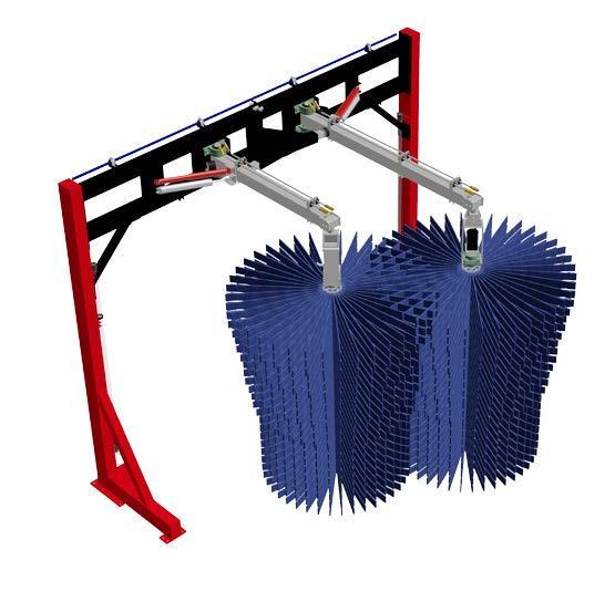
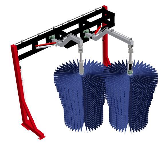
6 Product Specifications Aluminum or stainless steel frame and legs Double roller bearings New 6 Uni-Hubs with spindle 45 degree flex coupling standard Stainless steel brush hangers Hydraulic brush drive motors use 800PSI Electric drive available Shock absorber control Pneumatic retract controls standard Vehicle contour brush tracking 134 inches of tunnel length required (Straight Frame) 152 inches of tunnel length required (Jog Frame) 158 inches of tunnel width required 117 inches of unobstructed tunnel height required 1/2 inch city water connection This document is confidential and proprietary to SONNY S and cannot be used, disclosed or Page 6 of 36

7 Optional Related Equipment This document is confidential and proprietary to SONNY S and cannot be used, disclosed or Page 7 of 36


8 This document is confidential and proprietary to SONNY S and cannot be used, disclosed or Page 8 of 36

9 This document is confidential and proprietary to SONNY S and cannot be used, disclosed or Page 9 of 36

10 This document is confidential and proprietary to SONNY S and cannot be used, disclosed or Page 10 of 36
11 *INSTALLATION* Utilities Requirements UTILITIES INTERCONNECTION AND THE MATERIALS REQUIRED FOR INTERCONNECTION TO SONNY S EQUIPMENT ARE THE RESPONSIBILITY OF THE CUSTOMER! PERFORM ALL TRADES WORK TO ALL APPLICABLE LOCAL AND NATIONAL CODES! Water The Customer's Plumber is to provide and install a 3/4 inch city water (nominal) to the solenoid valve on the chemical distribution system for the Wrap. Electrical The Customer's Electrician is to provide and install single phase power from the Customer's remote push-button station through the tunnel equipment controller to the supplied air solenoid valve for retract of both wraparound brushes upon selective signal (see Figure #5 in Dimensions Section). The Customer s Electrician is to provide materials and install 208VAC or 230VAC or 460VAC, 3-phase, 60Hz power to the electric motor on the hydraulic power pack or VFD panel from a properly sized three pole circuit breaker and motor starter with three thermal overloads. Compressed Air The Customer's Plumber is to provide and install a 3/8 inch compressed air line 100PSI) from the Air Compressor to the supplied Air Distribution Manifold for Retract functions. The Customer's Plumber is to provide and install a 3/8 inch compressed air line 100PSI) from the Air Compressor to the supplied Air-Driven Pump Station for Foamer Chemical Application functions. Technical Disclaimer Although building codes have been considered in developing all drawings, verification of sitespecific conditions and compliance with federal, state and local building codes is the exclusive responsibility of the customer and/or architect and engineer. This document is confidential and proprietary to SONNY S and cannot be used, disclosed or Page 11 of 36
12 Dimensions Equipment Program - Manuals Figure #1 This document is confidential and proprietary to SONNY S and cannot be used, disclosed or Page 12 of 36
13 Figure #2 This document is confidential and proprietary to SONNY S and cannot be used, disclosed or Page 13 of 36
14 Figure #3 This document is confidential and proprietary to SONNY S and cannot be used, disclosed or Page 14 of 36
15 Figure #4 This document is confidential and proprietary to SONNY S and cannot be used, disclosed or Page 15 of 36
16 Figure #5 This document is confidential and proprietary to SONNY S and cannot be used, disclosed or Page 16 of 36
17 Standard Insert Patterns for a 28 Slot Hub 8 Position Material 12 Position Material 16 Position Material 28 Position Material Figure #6 This document is confidential and proprietary to SONNY S and cannot be used, disclosed or Page 17 of 36
18 Figure #7 This document is confidential and proprietary to SONNY S and cannot be used, disclosed or Page 18 of 36
19 Equipment Installation s Installation (Single Frame) Tools Consumables 1. Safety Glasses 1. Anti-Seize Compound 2. ½ Drive Ratchet Set 2. Marine Grease 3. Standard Combo Wrenches 4. Electric Impact Wrench 5. Permanent Marker 6. Tape Measure 7. 4' Level 8. C Clamps 9. Pry Bar 10. 1" Hammer Drill 11. Sledge Hammer Work Force Three (3) persons Time (assuming no problems) hours Installation Steps 1. Determine where the frame for the wrap is to be installed. Ensure the bottom gussets and feet of the frame face the same direction the brush hanger arms will face, normally the exit of the tunnel (see Figures #1 through #3 in the Dimensions Section and the tunnel layout drawings for your location). 2. Sweep any debris from where the frame will stand. 3. Check all hardware and place a small amount of Anti-Seize Compound on each bolt. 4. Place the Sonny s lift-a-ma-jig onto the frame of the Wrap and bolt into place. Bring the forklift into the lift-a-ma-jig. 5. Bring the frame into the building as close to its final position as is practical. Lift the frame into place. 6. Check that the Passenger Side Brush hanger arm is longer than the Driver Side, if not the frame is not positioned correctly. 7. Level and square the frame with the centerline of the equipment. (see Figure #1 in the Dimensions Section and the tunnel layout drawings for your location). This document is confidential and proprietary to SONNY S and cannot be used, disclosed or Page 19 of 36
20 Note: Before lagging the frame into position have a second person double check all measurements against your tunnel equipment layout drawings to ensure all measurements were performed correctly. 8. Place an Anchor Bolt in each corner. Tighten all hardware. 9. Check that the shock absorbers on each Brush Hanger do not "bottom out" in their fully extended position. If this occurs move the shock mounting position to a different hole on the mounting bracket to prevent a fully extended condition. 10. Move each brush hanger from the center of the wash tunnel so that it is parallel to vehicle travel. With each brush hanger in this position check that the hanger is level. Up or down adjustment of the brush hanger can be achieved by placing shim material under the brush hanger pillow block bearings. 11. Double check that the bottom pillow block bearing for each brush hanger is EXACTLY below the top pillow block bearing. This is necessary to provide light brush pressure against the side of the vehicle. 12. Mount the Brush Head, Shaft and Core assembly to each Hanger Arm. Connect the preplumbed hydraulic lines. Note: The SONNY'S supplied BLACK high pressure hose on the wraparound unit is for the hydraulic PRESSURE connection...the SONNY'S supplied ORANGE or RED high pressure hose on the wraparound unit is for the hydraulic RETURN connection. 13. Run and connect the 1/2 inch PRESSURE line from the Hydraulic Power Pack to the 1/2 inch male pipe thread fitting on the BLACK high pressure hose on the leg of the Wrap Around Washer. 14. Run and connect the 1/2 inch RETURN line to the Hydraulic Power Pack to the 1/2 inch male pipe thread fitting on the ORANGE or RED high pressure hose on the leg of the. 15. Run and connect the chemical lines from the Chemical Distribution Manifold to the chemical line on the Wrap frame for the application nozzles. 16. Rotation of the Brushes is with vehicle travel. As viewed from the top of each Brush the DRIVER side turns COUNTERCLOCKWISE and the PASSENGER side turns CLOCKWISE. Rotation speed of each Brush should be according to the Operating Speeds Chart in the Adjustments and Testing Section. 17. Run and connect the air lines from the Air Distribution Manifold to the air cylinder for each retract. 18. Install cloth on the Brush Cores according to the type of material being used. (See "Insert Patterns" in the Dimensions Section) This document is confidential and proprietary to SONNY S and cannot be used, disclosed or Page 20 of 36
21 s Installation (Spyder Frame) Tools Consumables 1. Safety Glasses 1. Anti-Seize Compound 2. ½ Drive Ratchet Set 2. Marine Grease 3. Standard Combo Wrenches 4. Electric Impact Wrench 5. Permanent Marker 6. Tape Measure 7. 4' Level 8. C Clamps 9. Pry Bar 10. 1" Hammer Drill 11. Sledge Hammer Work Force Three (3) persons Time (assuming no problems) hours Installation Steps 1. Determine where the Spyder is to be installed (see Figures #1 thru #3 in the Dimensions Section and the tunnel layout drawings for your location). 2. Sweep any debris from where the Spyder will stand. 3. Check all hardware and place a small amount of Anti-Seize Compound on each bolt. 4. Place the Sonny s lift-a-ma-jig onto the passenger s side of the Entrance end of the Spyder on the Frame of the Mitter and bolt into place. Bring the forklift into the lift-a-majig. Note: Place the Mitter legs as closely as possible to their final placement. 5. Bring the Mitter into the building as close to its final position as is practical. Lift the Mitter into place. 6. Place the Driver s and Passenger s side sections into position and bolt to the top. Do not over tighten snug only. Note the Driver s Side Section has a bolt for a stop on the tire brush frame. 7. Back the Mitter out and unclamp the Lift-a-ma-jig. 8. Clamp the Exit End Wrap to the forklift, using the Lift-a-ma-jig. Bring the Exit End Wrap into the exit end of the building. This document is confidential and proprietary to SONNY S and cannot be used, disclosed or Page 21 of 36
22 Note: Use a long pry bar to adjust location prior to adding the wraps into place. 9. Place the Wrap into the Mitter frame. Bolt the frame into place. Do not over tighten snug only. 10. Clamp the Entrance End Wrap to the forklift using a 2 x 4 to offset the slope of the floor. Bring the Entrance End Wrap into the entrance end of the building. 11. Place the Wrap into the Mitter frame. Bolt the frame into place. Do not over tighten snug only. 12. Level and square the frame with the centerline of the equipment (see Figures #1 in the Dimensions Section and the tunnel layout drawings for your location). Note: Before lagging the frame into position have a second person double check all measurements against your tunnel equipment layout drawings to ensure all measurements were performed correctly. Note: Before lagging the Mitter legs in place, loosen the tire brush support bracket this will allow you to move it later. 13. Place an Anchor Bolt in each corner. Tighten all hardware. 14. Move each Brush Hanger from the center of the wash tunnel so that it is parallel to vehicle travel. With each Brush Hanger in this position, check that the hanger is level. Up or down adjustment of the Brush Hanger can be achieved by placing shim material under the Brush Hanger Pillow Block Bearings. 15. Double check that the bottom Pillow Block Bearing for each Brush Hanger is EXACTLY below the top Pillow Block Bearing. This is necessary to provide light brush pressure against the side of the vehicle. 16. Check that the shock absorbers on each Brush Hanger do not "bottom out" in their fully extended position. If this occurs move the shock mounting position to a different hole on the mounting bracket to prevent a fully extended condition. 17. Mount the Brush Head, Shaft and Core assembly to each Hanger Arm. Connect the preplumbed hydraulic lines. 18. For the Entrance, Exit End Wraps run and connect a 1/2 inch PRESSURE line from the Hydraulic Power Pack to the 1/2 inch male pipe thread fitting on the BLACK high pressure hose on the leg of the Wraparound Brush. 19. For the Entrance, Exit End Wraps run and connect the 1/2 inch RETURN line to the Hydraulic Power Pack to the 1/2 inch male pipe thread fitting on the ORANGE or RED high pressure hose on the leg of the Wraparound Brush. 20. Run and connect the chemical lines from the Chemical Distribution Manifold to the chemical line on the Wrap frame for the application nozzles. This document is confidential and proprietary to SONNY S and cannot be used, disclosed or Page 22 of 36
23 21. Rotation of the Brushes is with vehicle travel. As viewed from the top of each Brush the DRIVER side turns COUNTERCLOCKWISE and the PASSENGER side turns CLOCKWISE. Rotation speed of each Brush should be according to the Operating Speeds Chart in the Adjustments and Testing Section. 22. Run and connect the air lines from the Air Distribution Manifold to the air cylinder for each retract. 23. Install cloth on the Brush Cores according to the type of material being used. This document is confidential and proprietary to SONNY S and cannot be used, disclosed or Page 23 of 36
24 Restrict-O-Flex Coupler Mounting Equipment Program - Manuals This document is confidential and proprietary to SONNY S and cannot be used, disclosed or Page 24 of 36
25 Adjustments and Testing Mechanical Adjustment of the Hanger Arms 1. Install the unit so that the legs are plumb, the hanger arms are level when at the rest position and the mounting bearings are positioned perpendicular to floor (No pitch). 2. The rest position will vary with operator preference and region. If front license plates are present the brushes should be open slightly to clear the plate, approximately one inch between when spinning. If there are no front plates then when spinning the tips of the cloth should be penetrating about one inch. 3. The two brushes should return to the rest position (middle of the tunnel) with no air pressure and no pitch to the bearings. Speed and Torque Adjustment 1. Hydraulic a. The speed of the brush can be adjusted on the flow control for the power pack. b. To increase the speed move the handle on the flow control closer to the number 10. c. To decrease the speed move the handle on the flow control closer to the number 1. d. The torque must be set prior to operation and should be set between 600 and 900 PSI. For information on how to set the torque please refer to the Hydraulic Power Pack Manual. 2. Electric a. The speed of the brush can be adjusted on the Variable Frequency Drive (VFD). b. To increase the speed adjust the Hertz on the VFD to a higher number. c. To decrease the speed adjust the Hertz on the VFD to a lower number. d. The Overload on the Motor Starter protector(s) must be set at the lowest level to allow for operation. Adjust the amps in accordance with motor(s) name plate Operating Speeds Chart Chain Speed Brush Speed Air Pressure Pass Air Pressure Driver 50-70CPH 70-75RPM 0PSI 0PSI 70-80CPH 80-85RPM 0-5PSI 0-5PSI 80-90CPH 85-90RPM 5-15PSI 5-10PSI CPH 90-95RPM 15-25PSI 10-15PSI This document is confidential and proprietary to SONNY S and cannot be used, disclosed or Page 25 of 36
26 Two Solenoid valves, one for each retract, are recommended for 80 or more cars per hour. To adjust the operation of the brushes without air pressure you may adjust the position of the pillow block bearings. 1. TO INCREASE THE PRESSURE ON THE SIDE AND BACK OF THE VEHICLE: Adjust the bottom pillow block bearing away from the center of the tunnel. Move in 1/8 inch increments at a time. 2. TO DECREASE THE PRESSURE ON THE SIDE AND BACK OF THE VEHICLE: Adjust the bottom pillow block bearing towards the center of the tunnel. Move in 1/8 inch increments at a time. Cloth penetration should be about three to four inches on the flat surface of the car. Each of the brushes should cover about two thirds of the back of the vehicle, overlapping in the center. This document is confidential and proprietary to SONNY S and cannot be used, disclosed or Page 26 of 36
27 *GENERAL OPERATION* Operation With the brushes rotating (with the direction of vehicle travel and at proper RPM) the vehicle front bumper contacts the driver side brush first and then the passenger side brush. The brushes move evenly across the front of the vehicle, each washing one half of the front, and gear around the front fenders to maintain steady contact while cleaning the sides of the vehicle. As the rear of the vehicle approaches the brushes they individually gear themselves around the rear fenders so that each brush washes one half of the vehicle rear vertical surfaces. As the vehicle departs the wraparound brush area the brushes are fully extended toward the center of the wash tunnel ready to accept another vehicle for washing. NOTE: Proper cloth penetration on flat vehicle surfaces should be 3 to 4 inches. As the wraparounds gear around corners, such as fenders, cloth penetration may be greater, but not deeper than half the distance to the aluminum brush core. Wrap Retract Operation When selected by the Operator's remote Programmer push button station the wraparound brushes will retract from the center of the wash tunnel toward the tunnel outer walls. This can be done individually if one solenoid is used for each arm. This is accomplished, when the push button is pressed, by completing an electrical circuit through the equipment Programmer to pass single phase power at the preset pulse count of the Programmer to the retract air solenoid valve. The air solenoid valve now opens and allows compressed air to pass through to the rod end port of each air cylinder causing the brush hangers to retract. This document is confidential and proprietary to SONNY S and cannot be used, disclosed or Page 27 of 36
28 DAILY Equipment Program - Manuals *PREVENTIVE MAINTENANCE* 1. Check all hydraulic, air and chemical lines and fittings for leaks. Repair, or replace, as needed. 2. Check both brush units for proper operation and retract operation, listening for any unusual noises from the equipment. 3. Inspect brush cloth for cuts, grease, or oil. Remove and repair, or replace, any cloth panel if any of these conditions are found. 4. Check for proper chemical solution delivery. WEEKLY 1. Inspect the Spring Flex couplings for secure mounting and freedom of movement and grease the Spring Flex couplings universal joints as required. 2. Grease the brush shaft four bolt flange bearings. Do not allow grease to come in contact with brush cloth. FOR THE FIRST MONTH OF OPERATION CHECK ALL HARDWARE AND FITTINGS FOR TIGHTNESS EACH WEEK. PERFORM THIS INSPECTION TO THE SCHEDULE SHOWN BELOW AFTER THE FIRST MONTH OF OPERATION. MONTHLY 1. Inspecting all hardware and fittings for tightness. 2. Grease the brush hanger pillow block bearings. Do not allow grease to come in contact with brush cloth. 3. Inspect soap solution spray nozzles for wear. Replace as necessary. 4. Thoroughly clean the equipment and framework. SEMI-ANNUALLY 1. Carefully inspect brush equipment cloth for wear and damage. Replace as necessary. This document is confidential and proprietary to SONNY S and cannot be used, disclosed or Page 28 of 36

29 *PARTS* Equipment Program - Manuals This document is confidential and proprietary to SONNY S and cannot be used, disclosed or Page 29 of 36

30 This document is confidential and proprietary to SONNY S and cannot be used, disclosed or Page 30 of 36

31 This document is confidential and proprietary to SONNY S and cannot be used, disclosed or Page 31 of 36

32 This document is confidential and proprietary to SONNY S and cannot be used, disclosed or Page 32 of 36

33 This document is confidential and proprietary to SONNY S and cannot be used, disclosed or Page 33 of 36

34 This document is confidential and proprietary to SONNY S and cannot be used, disclosed or Page 34 of 36

35 Equipment Program - Manuals *WARRANTY* SONNY S ENTERPRISES, INC. FACTORY LIMITED LIFETIME WARRANTY Equipment manufactured by SONNY S ENTERPRISES, INC. is warranted to be free from defect in material and workmanship. Welded metal framework and other non-moving, non-wearable fabricated metal components manufactured by SONNY S are warranted for the life of the equipment to the original purchaser. Fabricated metal wearable surface and moving components manufactured by SONNY S are warranted for a period of one (1) year to the original purchaser of the equipment. All components assembled to SONNY S equipment that are manufactured by others are warranted by the appropriate manufacturer and subject to that manufacturer s limited warranty. Contact SONNY S for the specific information on other component manufacturer s warranty terms. All new cloth shipped with new SONNY S equipment is warranted for a period of one (1) year or 80,000, whichever occurs first. This warranty is not assignable or transferable. The warranty period begins the first day following installation or 30 days from the original invoice date, whichever occurs first. The Seller s liability shall be limited to repair or replacement of materials found to be defective within the warranty period. In the event of repair or replacement this limited warranty is noncumulative. The Purchaser must supply the Seller with immediate written notice when any defects are found. The Seller shall have the option of requiring the return of defective material to establish the Purchaser s claim. Neither labor nor transportation charges are included in this warranty. Transportation damage claims are to be submitted to the carrier of the damaged materials. This warranty is based upon the Purchaser s reasonable care and maintenance of the warranted equipment. It does not apply to any equipment which has been subject to misuse, including neglect, accident or exposure to harsh chemicals or chemicals that react violently with: water, organic acids (e.g. acetic acid), inorganic acids (e.g. hydrofluoric acid), oxidizing agents (e.g. peroxides), and metals (e.g. aluminum). Chemicals corrosive to: aluminum alloys, carbon steel, and other metals. Nor does it apply to any equipment which has been repaired or altered by anyone not so authorized by SONNY S. Further, the equipment must be properly installed with proper accuracy of all specified plumbing, electrical, and mechanical requirements. This warranty does not apply to normal wear and tear or routine maintenance components. EXCEPT AS EXPRESSLY STATED HEREIN, SONNY S SHALL NOT BE LIABLE FOR DAMAGES OF ANY KIND IN CONNECTION WITH THE PURCHASE, MAINTENANCE, OR USE OF THIS EQUIPMENT INCLUDING LOSS OF PROFITS AND ALL CLAIMS FOR CONSEQUENTIAL DAMAGES. THE LIMITED WARRANTY EXPRESSED HEREIN IS IN LIEU OF ALL OTHER WARRANTIES EXPRESSED OR IMPLIED. SONNY S NEITHER ASSUMES NOR AUTHORIZES ANY PERSON TO ASSUME FOR IT ANY OTHER OBLIGATION OR LIABILITY IN CONNECTION HEREWITH. SONNY S The CarWash Factory This document is confidential and proprietary to SONNY S and cannot be used, disclosed or duplicated without prior written consent. Content, prices and availability subject to change without notice. SonnysDirect.com Page 35 of

36 *CUSTOMER SERVICE* Please contact SONNY S Equipment Department for installation and/or operational questions regarding this piece of equipment. Please refer to the Parts Catalog and contact SONNY S Customer Service Order Entry Department for any replacement parts for this piece of equipment. You can also visit the web at DEPARTMENT PHONE NUMBERS FAX NUMBERS Toll Free Main Line Equipment Department Or you can Sales at sales@sonnysdirect.com Thank you for being a SONNY S car wash equipment owner! From all of us here at This document is confidential and proprietary to SONNY S and cannot be used, disclosed or Page 36 of 36
Air Compressor. Owner s Manual. Sonny's Enterprises, Inc Hiatus Road Tamarac, Florida v1
 Owner s Manual Sonny's Enterprises, Inc. 5605 Hiatus Road Tamarac, Florida 33321 16v1 *Table of Contents* WARNING *SAFETY REQUIREMENTS* WARNING... 3 *INTRODUCTION*... 5 Product Specifications... 6 Optional
Cyclone Trash Separator
 Owner's Manual Sonny's Enterprises, Inc. 5605 Hiatus Road Tamarac, Florida 33321 16v1 *Table of Contents* WARNING *SAFETY REQUIREMENTS* WARNING... 3 *INTRODUCTION*... 5 Product Specifications... 6 *INSTALLATION*...
Top Brush Auto Retract (Zelio PLC)
") () Owner s Manual Sonny's Enterprises, Inc. 5605 Hiatus Road Tamarac, Florida 33321 16v1 *Table of Contents* Equipment Program - Manuals WARNING *SAFETY REQUIREMENTS* WARNING... 3 *INTRODUCTION*... 5 Product
() Owner s Manual Sonny's Enterprises, Inc. 5605 Hiatus Road Tamarac, Florida 33321 16v1 *Table of Contents* Equipment Program - Manuals WARNING *SAFETY REQUIREMENTS* WARNING... 3 *INTRODUCTION*... 5 Product
Over-Under Conveyor Soft-Drop
 Owner s Manual Sonny's Enterprises, Inc. 5605 Hiatus Road Tamarac, Florida 33321 16v2 *Table of Contents* Equipment Program - Manuals WARNING *SAFETY REQUIREMENTS* WARNING... 3 *INTRODUCTION*... 5 Product
BUG PREP KIT 2.0 HAND-PREP SYSTEM. User Manual REV A reva0616
 BUG PREP KIT 2.0 HAND-PREP SYSTEM User Manual REV A 4000110 reva0616 Hydra-Flex, Hydra-Flex, Inc. 2016 Inc. 2016 Page 1 TABLE OF CONTENTS Overview 3 Standard Bug Prep Kit 2.0 3 Bug Prep Retro Controller
MINI WRAP INSTALLATION MANUAL Part # WRAPMHYD[... ]01 WRAPMELE[... ]01 FOR COTTON CLOTH, STAR FOAM or C-CHANNEL FOAM BRUSHES
![MINI WRAP INSTALLATION MANUAL Part # WRAPMHYD[... ]01 WRAPMELE[... ]01 FOR COTTON CLOTH, STAR FOAM or C-CHANNEL FOAM BRUSHES](/thumbs/90/104454538.jpg "MINI WRAP INSTALLATION MANUAL Part # WRAPMHYD[... ]01 WRAPMELE[... ]01 FOR COTTON CLOTH, STAR FOAM or C-CHANNEL FOAM BRUSHES") MINI WRAP INSTALLATION MANUAL Part # WRAPMHYD[..... ]01 WRAPMELE[..... ]01 FOR COTTON CLOTH, STAR FOAM or C-CHANNEL FOAM BRUSHES TABLE OF CONTENTS Equipment Utilities Page: 1 Equipment Specifications Page:
MINI WRAP INSTALLATION MANUAL Part # WRAPMHYD[..... ]01 WRAPMELE[..... ]01 FOR COTTON CLOTH, STAR FOAM or C-CHANNEL FOAM BRUSHES TABLE OF CONTENTS Equipment Utilities Page: 1 Equipment Specifications Page:
HF4145 FOLDING MULTI-POSITION WORKOUT BENCH
 HF4145 FOLDING MULTI-POSITION WORKOUT BENCH Note: Both Serial Number and Model Number are Required when Ordering Parts RECORD SERIAL NUMBER HERE CATALOG NUMBER 0406-001 Customer Service (800) 548-5438
AQUA-LAB Chemical Dispensing System. Operating Manual REV L
 AQUA-LAB Chemical Dispensing System Operating Manual REV L Specifications 1. Operating water pressure: 200 psi (Factory set) 2. Pneumatics operating pressure: 100 psi (Factory set) 3. Maximum water source
F2B and S2S MITTERS INSTALLATION MANUAL Part # MTTRF360 [... ] and MTTRS360 [... ] ( ALL COLORS )
![F2B and S2S MITTERS INSTALLATION MANUAL Part # MTTRF360 [... ] and MTTRS360 [... ] ( ALL COLORS )](/thumbs/90/103874314.jpg "F2B and S2S MITTERS INSTALLATION MANUAL Part # MTTRF360 [... ] and MTTRS360 [... ] ( ALL COLORS )") Equipment Features F2B and S2S MITTERS INSTALLATION MANUAL Part # MTTRF360 [.... ] and MTTRS360 [.... ] ( ALL COLORS ) Aluminum Structure Color Skinz Snap On Structure Wrap 4 Baskets over-lapping design
Equipment Features F2B and S2S MITTERS INSTALLATION MANUAL Part # MTTRF360 [.... ] and MTTRS360 [.... ] ( ALL COLORS ) Aluminum Structure Color Skinz Snap On Structure Wrap 4 Baskets over-lapping design
Focus Flex Wrap. Service Manual W 34th St, Houston, TX
 Focus Flex Wrap Service Manual 5842 W 34th St, Houston, TX 77092 1.800.999.9878 1.713.683.9878 www.colemanhanna.com Find us on Facebook: /ColemanHannaCarwash Hanna Focus Flex Wrap Table of Contents Table
MOTOR CITY ROCKERZ INSTALLATION MANUAL Part # ROCKRHYD[... ] ROCKRELE[... ] (ALL COLORS)
![MOTOR CITY ROCKERZ INSTALLATION MANUAL Part # ROCKRHYD[... ] ROCKRELE[... ] (ALL COLORS)](/thumbs/89/99803499.jpg "MOTOR CITY ROCKERZ INSTALLATION MANUAL Part # ROCKRHYD[... ] ROCKRELE[... ] (ALL COLORS)") MOTOR CITY ROCKERZ INSTALLATION MANUAL Part # ROCKRHYD[....... ] ROCKRELE[....... ] (ALL COLORS) TABLE OF CONTENTS Equipment Specifications Page: 1 Equipment Features Page: 1 Suggested Tools and Installation
MOTOR CITY ROCKERZ INSTALLATION MANUAL Part # ROCKRHYD[....... ] ROCKRELE[....... ] (ALL COLORS) TABLE OF CONTENTS Equipment Specifications Page: 1 Equipment Features Page: 1 Suggested Tools and Installation
Read this entire manual before operation begins.
 Read this entire manual before operation begins. Record below the following information which is located on the serial number data plate. Serial No. Model No. Date of Installation Contents Specifications.............
Hanna Daily Preventive Maintenance Schedule
 Hanna Daily Preventive Maintenance Schedule Location Location # Daily operation and inspection procedures to be performed by car wash personnel. Mark status in the spaces on the right after performing
Read this entire manual before operation begins.
 Read this entire manual before operation begins. Record below the following information which is located on the serial number data plate. Serial No. Model No. Date of Installation Contents Specifications.............
Read this entire manual before operation begins.
 Read this entire manual before operation begins. Record below the following information which is located on the serial number data plate. Serial No. Model No. Date of Installation Contents Specifications.............
Outload Trough Roller Conveyor
 Outload Trough Roller Conveyor OWNER'S MANUAL 00003400 (8/99) Table of Contents Warranty Information.............................. Inside Front Cover Operator Qualifications / Sign Off Sheet..............................
Raydot LLC 24 Actuator (115 VOLT)
") Installation, Operation & Parts Manual Read carefully the information provided. Retain manual for future reference. Raydot LLC 24 Actuator (115 VOLT) 145 Jackson Ave. S. Cokato, MN 55321-USA (320) 286-2103
Installation, Operation & Parts Manual Read carefully the information provided. Retain manual for future reference. Raydot LLC 24 Actuator (115 VOLT) 145 Jackson Ave. S. Cokato, MN 55321-USA (320) 286-2103
SPECIFICATIONS Horsepower: 1.5 HP Running Maximum PSI: 125 PSI Tank Capacity: 15 Gallons CFM: 6 40 PSI 5 90 PSI
 15 GALLON AIR COMPRESSOR Model: 7678 DO NOT RETURN TO STORE Please call 800-348-5004 for parts and service CALIFORNIA PROPOSITION 65 WARNING: You can create dust when you cut, sand, drill or grind materials
Drive Over- Pit. Belt Accelerator & Multi-Purpose Belt Loader OWNER'S MANUAL (08/08)
") Drive Over- Pit Belt Accelerator & Multi-Purpose Belt Loader OWNER'S MANUAL 00028100 (08/08) Belt Accelerator & Multi-Purpose Belt Loader Table of Contents Warranty Information................. Inside
Drive Over- Pit Belt Accelerator & Multi-Purpose Belt Loader OWNER'S MANUAL 00028100 (08/08) Belt Accelerator & Multi-Purpose Belt Loader Table of Contents Warranty Information................. Inside
SYSTEM MANUAL. Automated Motorized Hydraulic Traffic Controller. Revision CS72-HTC
 CS72-HTC SYSTEM MANUAL Automated Motorized Hydraulic Traffic Controller Revision 2002.01 Spike Systems 3623 S. Seventh Street Phoenix, Arizona 85040 Phone: (602) 243-0291 Fax: (602) 243-0294 Hydraulic
Flip - Up Conveyor. for 10" BeltVeyors OWNER'S MANUAL (12/00)
") Flip - Up Conveyor for 10" BeltVeyors OWNER'S MANUAL 19023100 (12/00) Table of Contents Warranty Information............................ Inside Front Cover Operator Qualifications........................................
Flip - Up Conveyor for 10" BeltVeyors OWNER'S MANUAL 19023100 (12/00) Table of Contents Warranty Information............................ Inside Front Cover Operator Qualifications........................................
OWNERS MANUAL HF4550 PREACHER CURL. Customer Service (800) (858) Fax (858) RECORD SERIAL NUMBER HERE
 (858) Fax (858) RECORD SERIAL NUMBER HERE") OWNERS MANUAL HF4550 PREACHER CURL Note: Both Serial Number and Model Number are Required when Ordering Parts RECORD SERIAL NUMBER HERE CATALOG NUMBER 0805-001 Customer Service (800) 548-5438 (858) 578-7676
OWNERS MANUAL HF4550 PREACHER CURL Note: Both Serial Number and Model Number are Required when Ordering Parts RECORD SERIAL NUMBER HERE CATALOG NUMBER 0805-001 Customer Service (800) 548-5438 (858) 578-7676
1250 LB. CAPACITY MECHANICAL WHEEL DOLLY
 1250 LB. CAPACITY MECHANICAL WHEEL DOLLY 67287 SET-UP AND OPERATING INSTRUCTIONS Visit our website at: http://www.harborfreight.com Read this material before using this product. Failure to do so can result
24 Linear Actuator 115 Volts A.C. (Cat. # C430A)
") Installation, Operation & Parts Manual Read carefully the information provided. Retain manual for future reference. 24 Linear Actuator 115 Volts A.C. (Cat. # C430A) Page 1 of 8 IS10007.doc 11/15/06 IMPORTANT!
Installation, Operation & Parts Manual Read carefully the information provided. Retain manual for future reference. 24 Linear Actuator 115 Volts A.C. (Cat. # C430A) Page 1 of 8 IS10007.doc 11/15/06 IMPORTANT!
OWNERS MANUAL HF PAIR VERTICAL DUMBBELL RACK. Customer Service (800) (858) Fax (858) RECORD SERIAL NUMBER HERE
 (858) Fax (858) RECORD SERIAL NUMBER HERE") OWNERS MANUAL HF4459 5 PAIR VERTICAL DUMBBELL RACK Note: Both Serial Number and Model Number are Required when Ordering Parts RECORD SERIAL NUMBER HERE CATALOG NUMBER 0605-000 Customer Service (800) 548-5438
OWNERS MANUAL HF4459 5 PAIR VERTICAL DUMBBELL RACK Note: Both Serial Number and Model Number are Required when Ordering Parts RECORD SERIAL NUMBER HERE CATALOG NUMBER 0605-000 Customer Service (800) 548-5438
Read this entire manual before operation begins.
 Read this entire manual before operation begins. Record below the following information which is located on the serial number data plate. Serial No. Model No. Date of Installation Contents Specifications.............
OWNERS MANUAL HF
 OWNERS MANUAL HF4461-48 HORIZONTAL DUMBBELL RACK Note: Both Serial Number and Model Number are Required when Ordering Parts RECORD SERIAL NUMBER HERE CATALOG NUMBER 1005-000 Customer Service (800) 548-5438
HALLMARK INDUSTRIES INC
 Performance Part No. HP. CONVERTIBLE JET PUMP USER S MANUAL GPH of Water @ Total Discharge Pressure of 40 psi Max. Pressure Max suction (shallow well) Max Suction (deep well) Max GPM (@0 head) Max Discharge
CROSS-OVER INSTALLATION MANUAL Part # WRAPCHYD[... ]03 WRAPCELE[... ]03 FOR COTTON CLOTH, STAR FOAM or C-CHANNEL FOAM BRUSHES
![CROSS-OVER INSTALLATION MANUAL Part # WRAPCHYD[... ]03 WRAPCELE[... ]03 FOR COTTON CLOTH, STAR FOAM or C-CHANNEL FOAM BRUSHES](/thumbs/86/94253583.jpg "CROSS-OVER INSTALLATION MANUAL Part # WRAPCHYD[... ]03 WRAPCELE[... ]03 FOR COTTON CLOTH, STAR FOAM or C-CHANNEL FOAM BRUSHES") CROSS-OVER INSTALLATION MANUAL Part # WRAPCHYD[..... ]03 WRAPCELE[..... ]03 FOR COTTON CLOTH, STAR FOAM or C-CHANNEL FOAM BRUSHES TABLE OF CONTENTS Equipment Utilities Page: 1 Equipment Specifications
CROSS-OVER INSTALLATION MANUAL Part # WRAPCHYD[..... ]03 WRAPCELE[..... ]03 FOR COTTON CLOTH, STAR FOAM or C-CHANNEL FOAM BRUSHES TABLE OF CONTENTS Equipment Utilities Page: 1 Equipment Specifications
Twin Screw Undercar Conveyor
 Twin Screw Undercar Conveyor Owner s Manual #19015700 05-00 Table of Contents Operator Qualifications...................................... 1 Safety.................................................. 2-4
INSTALLATION INSTRUCTIONS
 Safety Notices... 1... 3 Specifications... 3 General... 3 Electrical... 3 Hydraulic Connections... 3 Components... 4 Assembly... 4 Implement Installation... 7 Hydraulic Connections... 9 Closed-Center Hydraulics...
Installation & Operation Manual. Electrak 10 Series / Electromechanical Linear Actuator
 www..com Installation & Operation Manual Electrak 10 Series / Electromechanical Linear Actuator INTRODUCTION Thomson has many years of experience designing and manufacturing linear actuators for a wide
ASSEMBLY STEP ONE STEP TWO STEP THREE STEP FOUR STEP FIVE
 ASSEMBLY STEP ONE Attach the front [18] and rear feet [14] to the frame using the nuts [8], washer [9] and bolts [10]. STEP TWO STEP THREE STEP FOUR STEP FIVE Attach the handlebar post [22] inserting into
OWNERS MANUAL HF4263
 OWNERS MANUAL HF4263 ADJUSTABLE AB / BACK HYPER BENCH Note: Both Serial Number and Model Number are Required when Ordering Parts RECORD SERIAL NUMBER HERE CATALOG NUMBER 0805-000 Customer Service (800)
Dual Pack Flex Wrap. Service Manual W 34th St, Houston, TX
 Dual Pack Flex Wrap Service Manual 5842 W 34th St, Houston, TX 77092 1.800.999.9878 1.713.683.9878 www.colemanhanna.com Find us on Facebook: /ColemanHannaCarwash Dual Pack Flex Wrap Chapter 1.0 Introduction
Model AM2 M40 Panel Installation, Operation, and Maintenance Manual
 Model AM2 M40 Panel Installation, Operation, and Maintenance Manual RECEIVING AND INSPECTION Upon receiving unit, check for any interior and exterior damage, and if found, report it immediately to the
Atlas PV-9WP Addendum
 Atlas PV-9WP Addendum 9,000 lb. Capacity Two-Post Overhead Lift The Atlas PV-9WP above ground hoist is 6 inches wider than the Atlas PV-9P, giving it an overall width of 141 (11 9 ) and a drive thru width
Deere G & GP Series Snow Wing Installation
 Deere G & GP Series Snow Wing Installation Model: Serial Number: Rev. 10/13 Rylind Manufacturing, Inc. 2801 Youngfield St Suite 250 Golden, CO 80401 Offices: 303-979-3548 Fax: 303-979-4730 www.rylind.com
MODEL HD-BTC. Installation, Operation & Repair Parts Information REV041416
 MODEL HD-BTC Installation, Operation & Repair Parts Information REV041416 TABLE OF CONTENTS SAFETY INSTRUCTIONS 1 DEFINITIONS 1 SPECIFICATIONS 2 INSTALLATION INSTRUCTIONS 2 OPERATING INSTRUCTIONS 2 MAINTENANCE
Feb 22, 2018 '67-69 Camaro & '68-74 Nova Bumpsteer Adjustment Kit
 Feb 22, 2018 '67-69 Camaro & '68-74 Nova Bumpsteer Adjustment Kit 10552 The following instructions are intended for professional installers. Speedtech Performance assumes NO responsibility for the installation
Owner s Manual SB5010 Broadcast Spreader. Caution: Read all Safety Instructions and Operating Instructions Carefully.
 Manufacture s Limited Warranty for Broadcast Spreader Owner s Manual SB00 Broadcast Spreader The limited warranty set forth below is given by Precision Products Incorporated with respect to new merchandise
CS Fiber Optic Splice Case. Instruction
 3 2179-CS Fiber Optic Splice Case Instruction 2179-CS Fiber Optic Splice Case Description 1.0 General 1.1 The 3M 2179-CS Fiber Optic Splice Cases are closures that can be used in buried, underground, aerial,
Lumina 28 Traction Drive Model: Battery Burnisher M28036TDQP OPERATION SERVICE PARTS CARE
 Lumina 28 Traction Drive Model: Battery Burnisher M28036TDQP OPERATION SERVICE PARTS CARE Table of Contents IMPORTANT SAFETY INSTRUCTIONS...1 OPERATING INSTRUCTIONS...2 INSPECTION...2 ELECTRICAL...2 BATTERIES...2
RUFNEX Series Low Profile Wrenches Operation and Maintenance Manual
 RUFNEX Series Low Profile Wrenches Operation and Maintenance Manual http://www.torsionx.com Use the RUFNEX Series Ultra-Low Profile Wrenches to install and remove large bolts that have minimal wrench clearance.
Installation, Operation & Maintenance Manual
 Installation, Operation & Maintenance Manual Picture may differ from your specific application For Pro-Fill kits with part numbers beginning in BG BL-175 9-20-13 General Information & Precautions This
Before installing your Roush Performance Product(s), read through the entire installation procedure and check to make sure all items are present.
, read through the entire installation procedure and check to make sure all items are present.") 2005-2006 Ford Mustang GT Legal / Stage 3 / Offroad Exhaust Kits for Roush Rear Valence Installation Instructions Application: 2005- Ford Mustang GT Model Must have Roush Rear Valence Kit #R03030061 Before
2005-2006 Ford Mustang GT Legal / Stage 3 / Offroad Exhaust Kits for Roush Rear Valence Installation Instructions Application: 2005- Ford Mustang GT Model Must have Roush Rear Valence Kit #R03030061 Before
INSTALLATION INSTRUCTIONS FOR MOUNTING HARDWARE KIT F-105K2.5
 MY SAFE T PLUS UNIT INSTALLATION INSTRUCTIONS FOR MOUNTING HARDWARE KIT F-105K2.5 This kit supports installation of SAFE T PLUS : MODEL # 41-140 (RED) MODEL # 41-180 (WHITE) MODEL #41-230 (BLUE) KEEP INSTRUCTIONS
CLEAN ROOM DEVICES, LLC "WHERE TUBING AND FITTINGS COME TOGETHER"
 CLEAN ROOM DEVICES, LLC "WHERE TUBING AND FITTINGS COME TOGETHER" CRD600 Automatic Fitting Inserter OPERATIONS MANUAL VERSION 2.1 LAST EDITED 7.25.14 DOCUMENT NUMBER 001 cleanroomdevices.com 1 Table of
EZ LINER EXPRESS USERS MANUAL
 EZ LINER EXPRESS 2013 Vehicle Service Group CHIEF'S LIMITED ONE-YEAR WARRANTY & LIABILITY Chief Automotive Technologies warrants for one year from date of installation and/or purchase any components of
INSTALLATION INSTRUCTIONS For Model 855 Wolo Express TM
 INSTALLATION INSTRUCTIONS For Model 855 Wolo Express TM 12-Volt Train Horn Your purchase of a WOLO EXPRESS TRAIN HORN is the choice that will complement your vehicle. Wolo s products are manufactured with
CRD600 Automatic Fitting Inserter
 CRD600 Automatic Fitting Inserter OPERATIONS MANUAL VERSION 2.3 LAST EDITED 12.07.2018 cleanroomdevices.com 1 Table of Contents Title Page.. 1 Table of Contents. 2 1.0 General Product & Safety Information...3
ATD Gallon Pressurized Oil Drain Owner s Manual
 ATD-5203 30 Gallon Pressurized Oil Drain Owner s Manual TECHNICAL SPECIFICATIONS Model: ATD-5203 Capacity: 30 Gallon Drain Funnel Working Height: 47.25 to 70.5 Drain Funnel Diameter: 15.75 Plastic Tray:
Read this entire manual before operation begins.
 Rev. 12/12/2017 Read this entire manual before operation begins. Record below the following information which is located on the serial number data plate. Serial No. Model No. Date of Installation Contents
CRD610 Automatic Fitting Inserter
 CRD610 Automatic Fitting Inserter OPERATIONS MANUAL VERSION 1.2 LAST EDITED 12.12.2018 cleanroomdevices.com 1 Table of Contents Title Page. 1 Table of Contents...2 1.0 General Product & Safety Information....3
11 ½" MODEL SINGLE CHAIN CONVEYOR
 11 ½" MODEL SINGLE CHAIN CONVEYOR USER S MANUAL 11 ½" Chain conveyor Revision 2011-05-31 2 CONTENTS WARRANTY...3 FOREWORD...4 SAFETY PRECAUTIONS...5 ASSEMBLY INSTRUCTIONS...6 SPECIFICATIONS...6 ASSEMBLING
Low Profile Wrenches Operation and Maintenance Manual
 Low Profile Wrenches Operation and Maintenance Manual http://www.torquetoolsinc.com Use the HEXPRO Series Low Profile Wrenches Model 2HP 4HP 8HP 14HP 30HP to install and remove large bolts that have minimal
OBAE, OBAEXU, ON BOARD Battery Chargers
 C O R P O R A T IO N O P E R A T I N G I N S T R U C T I O N S OBAE, OBAEXU, ON BOARD Battery Chargers INTRODUCTION: The OBAE line of chargers are designed for the permanent installation on battery powered
Installation Instructions
 Equipment Required: Installation Instructions Fastener Kit: F Wrenches: 8mm, 13mm, 3/4, 15/16 Drill Bits: 1/4 Other Tools: Drill, Reciprocating Saw, File WARNING: Under no circumstances do we recommend
Installation, Operation & Maintenance Manual. For Pro-Fill kits with part numbers beginning in BG
 Installation, Operation & Maintenance Manual For Pro-Fill kits with part numbers beginning in BG BL-175 6/26/2009 General Information & Precautions This publication provides detailed instructions for installing
Linear Actuator. Installation Manual. warranty installation parts list. Linear Actuator Installation Manual Page 1
 Linear Actuator Installation Manual warranty installation parts list January 2004 Linear Actuator Installation Manual Page 1 MA1221B12 Warranty Information Chore-Time Equipment ( Chore-Time ) warrants
OWNER S GUIDE 8A DURALIFT II 13,200 LB. CAPACITY. Link Mfg. Ltd th St. N.E. Sioux Center, IA USA
 OWNER S GUIDE 8A000715 DURALIFT II 13,200 LB. CAPACITY Link Mfg. Ltd. 223 15th St. N.E. Sioux Center, IA USA 51250-2120 www.linkmfg.com QUESTIONS? CALL CUSTOMER SERVICE 1-800-222-6283 DEALER / INSTALLER:
PRYCO, INC. P. O. BOX 108 Mechanicsburg, IL OPERATIONS AND MAINTENANCE MANUAL For PUMP SETS
 PRYCO, INC. P. O. BOX 108 Mechanicsburg, IL 62545 Telephone: 217 / 364-4467 Fax: 217 / 364-4494 OPERATIONS AND MAINTENANCE MANUAL For PUMP SETS WHAT TO DO FIRST Upon receiving your new pump set system
Model ET 5000W Operation and Service Manual
 Model ET 5000W Operation and Service Manual Patented 5/16 BALL Load Capacity: 5000 lbs The ET 5000W ESCALATE TRAILER offers ground level roll-on loading and roll-off unloading of equipment with non-tilting
HexPro Series Low Profile Wrenches
 HexPro Series Low Profile Wrenches Operation and Maintenance Manual Model 2HP 4HP 8HP 14HP 30HP www.torquetoolsinc.com Use the HEXPRO Series Low Profile Wrenches Model 2HP 4HP 8HP 14HP 30HP to install
OWNERS MANUAL HF4261
 OWNERS MANUAL HF4261 ADJUSTABLE AB BENCH Note: Both Serial Number and Model Number are Required when Ordering Parts RECORD SERIAL NUMBER HERE CATALOG NUMBER 0905-000 Customer Service (800) 548-5438 (858)
Installation Instructions / Warranty
 Installation Instructions / Warranty Axor Montreux 16532XX1 Axor Montreux 16534XX1 Axor Montreux Wall-Mounted Widespread Lavatory Set 16532XX1 Cross handles 16534XX1 Lever handles 16532XX1 16534XX1 Technical
Garden Hose Reel with 3/4In. x 100Ft. Hose. Owner s Manual
 Garden Hose Reel with 3/4In. x 100Ft. Hose Owner s Manual WARNING: Read carefully and understand all ASSEMBLY AND OPERATION INSTRUCTIONS before operating. Failure to follow the safety rules and other basic
TAILGATE SPREADER INSTALLATION & OWNER S MANUAL TABLE OF CONTENTS
 A Division of Northern Star Industries, Inc. P.O. Box 788 Iron Mountain MI 49801-0788 www.bossplow.com SMARTHITCH 1100 TAILGATE SPREADER INSTALLATION & OWNER S MANUAL TABLE OF CONTENTS S & CAUTIONS...
NECO Pumping Systems
 INSTALLATION OPERATION & MAINTENANCE INSTRUCTIONS For Your NECO Pumping Systems PACKAGED CIRCULATING SYSTEM THIS COMPLETELY ASSEMBLED, TESTED, PACKAGED CIRCULATING SYSTEM IS OF THE HIGHEST QUALITY AND
READ AND SAVE THESE INSTRUCTIONS. Centrifugal Downblast Exhaust Fan Belt Driven for Roof & Wall Mounting
 READ AND SAVE THESE INSTRUCTIONS INSTALLATION, OPERATING INSTRUCTIONS & PARTS MANUAL Centrifugal Downblast Exhaust Fan Belt Driven for Roof & Wall Mounting Electrical wiring and connections should be done
2000SR. Installation Instructions May Donovan Enterprises 3353 S.E. Gran Park Way Stuart, Florida
 311499-Donovan 4/28/04 11:22 PM Page 1 Installation Instructions May 2003 Donovan Enterprises 3353 S.E. Gran Park Way Stuart, Florida 34997 1-800-327-8287 Visit our web site at: www.donovan-ent.com 311499-Donovan
User Guide IGD Series
 US User Guide IGD Series DANGER PRIOR TO USE, READ AND UNDERSTAND PRODUCT SAFETY INFORMATION. Failure to follow the instructions may result in ELECTRICAL SHOCK, EXPLOSION, or FIRE, which may result in
Installation Instructions PART NUMBERS: 76192, 84192, CQT76192
 Installation Instructions LIMITED LIFETIME WARRANTY To prevent SERIOUS INJURY, DEATH or PROPERTY DAMAGE: ALWAYS read, understand and follow warnings and instructions for your hitch BEFORE installation.
15-17 FORD MUSTANG GT
 15-17 FORD MUSTANG GT IMPORTANT! WARRANTY AND Please Forward All Information to Consumer Be sure to review the enclosed instructions prior to beginning the installation process. If you have any questions
Installation Instructions / Warranty
 Installation Instructions / Warranty Citterio 39136XX1 39156XX1 Citterio 39236XX1 Axor Citterio Widespread Lav Mixer 39136XX1 Axor Citterio Bidet Mixer 39236XX1 39136XX1 User instructions Turn the right
INSTRUCTION MANUAL L WIND CONE
 Cooper Industries DOCUMENT September 29, 2009 Revision B Crouse-Hinds Division Crouse-Hinds Airport Lighting Products 1200 Kennedy Road Windsor, CT 06095 860 683-4300 Fax 860 683-4354 Title: INSTRUCTION
IBT Series Square Drive Torque Wrenches
 IBT Series Square Drive Torque Wrenches Operation and Maintenance Manual Model.75, 1, 3, 5, 8, 10, 20, 25, 35, 50 http://www.torsionx.com Use the IBT Series Square Drive Torque Wrenches Model.75, 1, 3,
Extreme Duty Grapple (Rock, Skeleton, Scrap & Tine) Operation and Maintenance Manual
 Operation and Maintenance Manual") Extreme Duty Grapple (Rock, Skeleton, Scrap & Tine) Operation and Maintenance Manual Revision Date: May 12, 2017 Skid Pro PO Box 982 Alexandria, MN 56308 Toll Free: 877-378-4642 www.skidpro.com TABLE OF
Extreme Duty Grapple (Rock, Skeleton, Scrap & Tine) Operation and Maintenance Manual Revision Date: May 12, 2017 Skid Pro PO Box 982 Alexandria, MN 56308 Toll Free: 877-378-4642 www.skidpro.com TABLE OF
SPECIFICATIONS CONTENTS: Specifications Warning Information. Operating Instructions Preventative Maintenance Troubleshooting
 Model 3182 2,500 Lbs Power Train Table/Lift OWNER'S MANUAL CONTENTS: Page 1 Page 2-3 Page 3 Page 4 Page 5 Page 5 Page 6 Page 7 Page 8 Specifications Warning Information Setup Operating Instructions Preventative
Read this entire manual before operation begins.
 Read this entire manual before operation begins. Record below the following information which is located on the serial number data plate. Serial No. Model No. Date of Installation Contents Specifications.............
LOR Series Trig-O-Matic Lite Overload Release Clutch
 LOR Series Trig-O-Matic Lite Overload Release Clutch P-3029-BG LOR Series Installation and Operation An Altra Industrial Motion Company Contents I. Introduction A. Operating Principle... 3 B. Torque Adjustment...
Installation Instructions and Warranty Information
 Installation Instructions and Warranty Information 1999 2003 Ford SuperDuty Truck and Excursion Part# 1669S, 1669S-1, 1669S-2 Read all instructions carefully before attempting installation. Rev. 10/05
Installation Instructions and Warranty Information For Ford F-250 & F-350 Trucks with 7.5L V8 Auto. Transmission Only
 Installation Instructions and Warranty Information For 1988-1998 Ford F-250 & F-350 Trucks with 7.5L V8 Auto. Transmission Only Part# 1629SJT, 1629-1SJT, Requires part# 1629YJT, 1629Y-1JT, 1629Y-2JT, or
Owners Manual. LifeGuard Power Lift Model # Rev. 2/1/13
 Owners Manual LifeGuard Power Lift Model #100287 Rev. 2/1/13 Table of Contents 1. ASSEMBLY INSTRUCTIONS 3-5 A. Lift Assembly 3 B. Setup 3 1. Clinch Pin Location Drawings 4 2. Down Tube and Seat Assembly
HEAVY DUTY WHEEL LIFTER
 OWNER S MANUAL PRODUCT CODE: BTWD750 HEAVY DUTY WHEEL LIFTER Capacity Lift Arm Lifting Tilt Range Dimensions Net (Max) Spread Range (degrees) (L x W x H) Weight 750kg 533-635mm 60-275mm -2.5-10mm 787x1092x895mm
Model LA 4400 Time Delay OFF Controller
 ISIMET LA Series Model LA 4400 Time Delay OFF Controller Installation, Operation and Maintenance Manual Application: The Time Delay OFF Controller with integral 24-hr. programmable time clock operates
Owner s Manual, Operating Instructions Manual, and Replacement Parts Manual. Lift-Rite Hand Pallet Trucks Model SS45
 Owner s Manual, Operating Instructions Manual, and Replacement Parts Manual Lift-Rite Hand Pallet Trucks Model SS45 This publication, 1188027A, applies to the Lift-Rite Hand Pallet Truck, Model SS45 and
CLEAN ROOM DEVICES, LLC "WHERE TUBING AND FITTINGS COME TOGETHER"
 CLEAN ROOM DEVICES, LLC "WHERE TUBING AND FITTINGS COME TOGETHER" CRD600AF Automatic Fitting Inserter With Auto Feed OPERATIONS MANUAL (Shown with optional alcohol dispenser) 1 VERSION 1.1 LAST EDITED
SKID STEER COMBO PLOW
 A DIV. OF NORTHERN STAR INDUSTRIES, INC. P.O. BOX 788 IRON MOUNTAIN, MICHIGAN 49801 SKID STEER COMBO PLOW INSTALLATION & OWNER S MANUAL TABLE OF CONTENTS SAFETY PRECAUTIONS... 2 ASSEMBLY PROCEDURE... 3
456 Series Hydra-Lift Drum Rollers Operator s Manual for Morse Hydra-Lift Drum Rollers 456 Series
 Contents Page Receiving Procedures.................... 1 Warranty............................. 1 Safety Information..................... 1-2 Machine Description................... 3 Options.........................
RAPID ROLLER OPERATOR S MANUAL. L&C ENTERPRISES - U.S.A, Inc N.75 Drive, Escanaba, MI OWNER S NAME MODEL
 RAPID ROLLER OPERATOR S MANUAL OWNER S NAME MODEL SERIAL NUMBER DATE OF PURCHASE L&C ENTERPRISES - U.S.A, Inc. 6652 N.75 Drive, Escanaba, MI 49829 906-786-1008 1-866-786-1009 LIMITED WARRANTY L&C Enterprises-USA,
Users Guide for Ac-sync
 Problem solved. Users Guide for Ac-sync Thank you for choosing Anywhere Cart! The AC-SYNC is designed to sync, charge and store 1-36 ipads or tablets. Adjustable device divider bays allow fitment of any
Installation Instructions
 Equipment Required: Fastener Kit: F Wrenches: 3/4, 15/16 Drill Bits: 1/4 Other Tools: Drill Short & Long Bed All Megacabs 9464/9474 HIDE-A-GOOSE HITCH INSTALLATION WARNING: Under no circumstances do we
AUTO REWIND AIR HOSE REEL
 Model #s 46845, 46848 AUTO REWIND AIR HOSE REEL OPERATOR S MANUAL STORE THIS MANUAL IN A SAFE PLACE FOR FUTURE REFERENCE!? NEED HELP? Save time, contact us first. 888-648-8665 support@tekton.com WARNING:
Installation Instructions / Warranty
 Installation Instructions / Warranty Axor Citterio 39133XX1 Axor Citterio 39135XX1 Axor Citterio 39233XX1 Axor Citterio 39235XX1 Axor Citterio Widespread Lavatory Faucet Axor Citterio Widespread Bidet
Pontoon and Tri-Toon Bunk Assembly Instructions
 Pontoon and Tri-Toon Bunk Assembly Instructions INTRODUCTION The Starr line of Boat Lift Canopy Frames by Great Lakes Entry Systems has been engineered to provide the best possible performance, long term
Installation Instructions
 Equipment Required: Fastener Kit: F Wrenches: 15/16, 10 mm Drill Bits: 1/4 Other Tools: Drill, Reciprocating Saw 9464/9474 HIDE-A-GOOSE HITCH INSTALLATION All Fasteners Typical, Both Sides WARNING: Under
ROLLER SPREADER. Model - #171A-M Lee's Chapel Road Browns Summit, NC Tel: (800) Fax: (336) Web:
 Fax: (336) Web:") ROLLER SPREADER Model - #171A-M2 2949 Lee's Chapel Road Browns Summit, NC 27214 Tel: (800)-901-8037 Fax: (336)-375-1112 Web: www.jltclamps.com G@MAN#171A-M2-R1 2/11/04 SAH INTRODUCTION Company Introduction
ROLLER SPREADER Model - #171A-M2 2949 Lee's Chapel Road Browns Summit, NC 27214 Tel: (800)-901-8037 Fax: (336)-375-1112 Web: www.jltclamps.com G@MAN#171A-M2-R1 2/11/04 SAH INTRODUCTION Company Introduction
before serial number 2214
 before serial number 2214 Contents Page Safety Rules... 3 Pre-operational & Safety Inspection... 4 Operating Instructions... 6 Transport... 12 Maintenance & Routine Service... 12 Specifications... 14 SAFETY
Operators Manual. Recirculating Chiller /06/08
 Operators Manual Recirculating Chiller 110-197 11/06/08 Table of Contents Section 1. General Information 1.1 Warranty 1.2 Unpacking 1.3 Package Contents 1.4 Description of the Recirculating Chiller 1.5