This is a team contest to give students the opportunity to develop and show their talents of teamwork and engine building skills.
|
|
|
- Maximilian Cross
- 6 years ago
- Views:
Transcription
1 Engine Builder Team Contest This is a team contest to give students the opportunity to develop and show their talents of teamwork and engine building skills. Scope of Contest A team of five students will compete in a written contest at the region level. Each team member will take an exam consisting of 30 multiple choice ASE/NATEF type questions on Engine Repair and Diagnosis. The team member scores will then be averaged to determine the overall team score. The team with the highest average will represent that region at the state hands-on contest. The state contest will put eight teams (one team from each region) in a head-to-head engine builder shootout. Students will disassemble and reassemble a 350 Chevrolet engine. The teams will be judged on sportsmanship, quality of work, use of safe work practices, professionalism, as well as the finished product. Clothing Requirements: Region contest: Students will dress in an appropriate manner to stay within the spirit of the event. Students should be neatly dressed, with shirt tucked in and pants at the waist. Hats will not be allowed. State contest: Khaki type pant (no jeans), pullover solid color collared shirt (team should all be the same color); black or brown leather work shoes, and safety glasses with side shields or goggles. (Prescription glasses can be used only if they are equipped with side shields. If not, they must be covered with goggles.) Baseball style hats will be allowed at this event, but must be worn with bill facing the direction of travel. No hats will be worn backwards. Work
2 shoes/boots meeting ANSI Specifications or rubber soled, oil resistant shoes. Eligibility: Open to active SkillsUSA GA members enrolled in a CTAE Transportation Logistical Support program with entry-level skills for the occupational objective. Team members can be from different schools as long as they are served by the same automotive program. (Example: Students from South Effingham High School and Effingham County High School that attend Effingham College and Career Academy would be eligible to compete as a team.) Teams cannot be built from students that attend high schools that are served by different instructors. (Example: Peach County High School, Dodge County High School, and Hutchings Career Center cannot build a team. Each school has its own instructor; therefore each school would have a team.) Safety Requirement: Both the instructor and the contestant certify by agreeing to enter this contest that the contestant has received instruction and has satisfactorily passed an examination on the safe use of all tools. Further they agree that Skills USA, the Skills USA Championships Technical Committee and judges are released from all responsibility relating to personal injuries resulting from their use. Contestants will be removed from competition if proper training has not been provided and/or they are using the equipment in an unsafe manner.
3 Equipment and Materials: Supplied by host school: 1. All necessary service publications for the contestants (this will be sent prior to the contest to the host school) 2. All necessary information and furnishings for judges and technical committee (this will be sent to the host school) Supplied by Contestant: Safety glasses All necessary tools and equipment for the contest. No power tools will be used! Skill/Test Region Contest: The region contest will consist of a 5 member team. Each team member will take an exam consisting of 30 multiple choice ASE/NATEF type questions. Each individual exam will be scored and then averaged for the overall team score. The team with the highest average will then represent their region at the state hand-on engine builder contest. If the first place team is unable to represent that region then the second place team will be the representative. The members taking the exam must be the same students that compete in the hands on contest. State Contest: General Rules for Disassembly/Reassembly
4 The state contest will consist of a 5 member team from each region for a total of eight teams. There will be 4 team members allowed to work as assemblers of the engine with one member of the team who must remain behind the table to act as a support person to keep parts, tools, and specification sheets in order. This is a timed event which the best score after penalties will deem the winner. Students will start with a Lemans style start from the back of the parts/tools table and enter assembly/disassembly area from the left end. At this point students will begin to disassemble their engine. All parts, with the exception of the crankshaft, must be removed and placed on the parts table before reassembly. These are the parts that must be removed from assembly: Carburetor Intake Spark plugs Headers Cylinder heads (valves/valve springs do not have to be removed) Valve train (pushrods, lifters, etc ) Camshaft, timing chain and cam sprocket Oil pump Pistons and connecting rods (rings do not have to be removed from pistons) Distributor and wires All tin (oil pan, timing cover, valve covers, air cleaner) Harmonic balancer
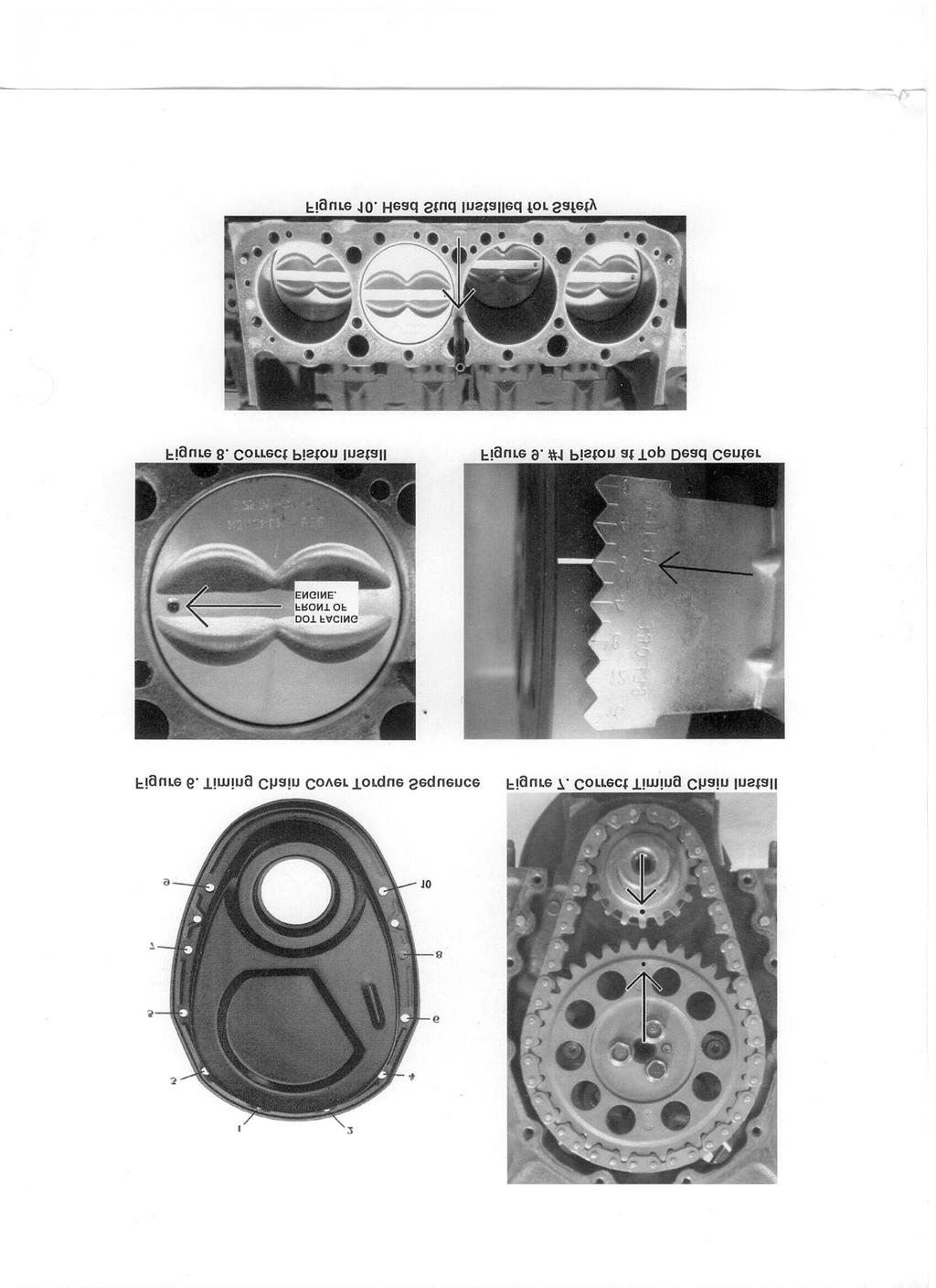
5 All members should them move to the back of the parts table around the left end for the judge to check assembly to determine if disassembly is complete. Once checked the team should proceed with reassembly. All parts must be reinstalled in proper manner and in the correct location (Example: number eight piston should be in number eight hole). All fasteners must be torqued to manufactures specifications. Torque wrench must be set by team member and checked by the judge prior to torqueing the fasteners. Correct torque sequence must be followed or a time penalty will be added to the final score. Penalties will also be added for improper torqued fasteners. Valve Adjustment Before the engine is completely assembled, the valve train must be properly adjusted. The following components and any other components that must precede them in reassembly should be installed before beginning the valve adjustment. Cylinder heads, valve train, timing chain, damper, and damper turning tool should be installed. Valves can only be properly adjusted when the lifter is resting on the camshafts base circle. Improper valve adjustment will result from adjusting the valve while the lifter is on the camshaft lobe or lobe ramp. Use the following guide to insure the lifter is resting on the camshafts base circle before valve adjustment. With the #1 piston at TDC (top dead center) on the compression stroke you may adjust the following valves: Intake Valves- #1, #2, #5, #7
6 Exhaust Valves- #1, #3, #4, #8 Now rotate the engine clockwise 360 degrees. The #1 piston should again be at TDC, only this time it s the exhaust stroke. Coincidently the #6 piston is now at TDC on the compression stroke. You may adjust the following valves: Intake Valves- #3, #4, #6, #8 Exhaust Valves- #2, #5, #6, #7 Use the following procedure to adjust the valve. You will start with the rocker arm nut loose. Slowly tighten the rocker arm nut with one hand while rotating the pushrod back and forth with your other thumb and index finger until you feel a slight drag. At this point there should be no valve lash (extra clearance). Now turn the rocker arm nut an additional 3/4 turn. Now the valve is properly adjusted. Disassembly 1) All components to be placed on table, no engine components on floor (subject to venue). Tools can be placed on floor while in use, but cannot remain there during competition. 2) Torque wrenches cannot be placed on floor at any time during the event, but can be held by a team member or placed in /on a padded tray or returned to the work bench.
7 3) Rotating torque will be determined by judge at the beginning of disassembly. (Reassembly torque must be within 25 % of original spec.) 4) Air cleaner - must be removed from carburetor separately. 5) Distributor and spark plug wires can be taken off as an assembly. 6) Headers and gaskets (headers must be removed as separate procedure before head comes off). Hand wrench only tool permitted for this procedure 3/8" 6 or 12 pt. No ratchet wrenches. 7) Spark plugs must be removed before heads come off engine. 8) Oil filter must use filter wrench to loosen. 9) Water pump. NO removal sequence. 10) Intake manifold (see de torque sheet, sheet can be used as referenced during event). 11) Remove balancer - before removal you must remove the adaptor before removing with puller. Balancers have been honed to aid in fitting. Once balancer has been removed, engine can only be turned over the following ways. (1) With crank socket (2) balancer installed with crank bolt and adaptor bolted to balancer. Time penalty will be 10 minutes each occurrence. 12) Heads - fasteners must be removed in de torque sequence one side at a time. (See sheet, once again can be used during event). Number one (1) head bolt has been replaced with stud. The nut size is 1/2" 12 pt. Torque value is the same.
8 13) Rocker arms, balls, nuts, (Individual Rocker arm, ball, and nut may be removed as an assembly) push rods, and lifters must be removed individually and placed in holder (supplied or approved holder) before heads come off. Both sides of engine can be worked on at this time, but heads must come off one side at a time. Penalty minutes will be assessed if rocker arms, push rods, and lifters are mixed up and not in place in holder or assembled incorrectly. 14) Pistons - block will remain in upright position deck up oil pan side down. Removal and install of all components will be made with engine in this position. 15) Remove oil pan. No removal sequence 16) Oil pump and drive. 17) Timing chain cover (remember oil pan must be off or loose in front before removing) - timing chain - cam gear - crank gear can remain on crankshaft; gear has been honed to slide to aid procedure. 18) Rod bolt protectors must be used. When a rod cap is loosened, that rod/piston assembly must be removed from block before proceeding to the next assembly. No multiple removals of rod caps or nuts will be permitted. A 5 minute penalty each rod and piston assembly that is loosened before a single assembly is removed. Holders must be placed on table to complete disassembly process, cannot remain in work area, but can be brought to engine for disassembly. 19) Gaskets from engine must be placed on table. If timing chain cover gasket and or water pump gaskets rip, stick or are damaged use the new supplied gaskets. All components are to be placed on table (i.e. clean work area).
9 20) All students to return behind table / workstation using LEFT side when disassembly is complete - judges to check area, ONLY THE TIME KEEPER can call students to return to work. If time keeper judge does not call students back immediately, this means tools or components are still in work area (team s responsibility to police area). 21) Instructor / coaches can observe from behind the table, but cannot physically be involved with disassembly or reassembly. They cannot coach or direct but can be there only to observe. They are not allowed to talk to and/or give signals/signs to the contestant. ASSEMBLY 22) Piston and rod assembly, along with crank journal, must be oiled prior to assembly during reassembly process. 23) Lifters - must use installation lube before installing (supplied). Also must be in proper bores, penalty if not. 24) Oiling of head bolts - pistons - bearings can be performed by second student during assembly process only and must be called out to judge. 25) Torque wrenches cannot be placed on floor at any time during event, but can be held by team member, placed in padded tray or returned to table.
10 26) No speed wrenches or t handles can be used for reassembly of the following components, intake manifold, headers, spark plugs, carburetors, rocker arm nuts, rod bolt nuts, water pump bolts, timing gear bolts, dampener bolt and adapt. 27) Engine must remain with decks up, oil pan side down during reassembly. 28) Bolts & Nuts. All bolts must be hand started then tightened to spec. No loading of nuts or bolts into sockets. A 2 minute penalty for each fastener. 29) Approved speed wrenches or t-bars may be used to run head bolts down before two step torque procedure. 30) Oiling of engine components can only be done during reassembly process and must be called out to judge. 31) Pistons reinstalled one piston at a time using ring compressor, band type or plier s type must be used. No speed sleeves, rod bolt protectors must be used. You must oil pistons before ring compressor use. 32) Rings must be clocked before reassembly and called out to judge, penalty if not. Rings: no bent/damaged rings will be allowed to be installed in engine. If you damage a ring, you must remove piston and remove damaged ring. Rings must be spaced 180 before installation, show judge. 33) No multiple loading of pistons in ring compressors before reassembly. When reassembly starts, student at table may ready one piston/rod assembly at a time. Rod journals must be oiled and called out to judge.
11 34) Rod nuts must be torqued to spec. Click type torque wrench to be used "must be shown to judge before use". If not, penalty will be assessed. Two step on rod nut torque. Penalty if not shown and called out to judge.
12 35) Proper installing and tightening of pistons and rods. Rods must be torqued in two (2) steps 15 lbs. and 30 lbs. Install one (1) piston and rod at a time per crank journal (example #1 and #2 is one journal) Crank journal must be in the down position for that set of pistons and rods. Install rod caps and snug nuts proceed to next journal #3 and #4, then #5 and #6 then #7 and #8. Each time the crank is rotated it must be called out to judge. There will be a 1 minute penalty will be for the first time and a warning issued, a 2 minute penalty for the second time, a 3 minute penalty for the third time, and a 4 minute penalty for the fourth time the crank is turned without calling JUDGE ROTATING CRANK. Once all rod caps are installed and nuts tightened the torque procedure may begin. At the beginning of the install call out to judge. 36) Cam gear and timing chain installation #1 piston must be up in TDC position. Timing marks with chain installed must be dot to dot (see fig. #7). There is a 3 minute penalty not showing judge dot to dot. 37) Proper torque specs on timing gear bolts, torque wrench shown to judge before use. 38) Install oil pump, torque to spec, show judge torque wrench. 39) Install timing chain cover and oil pan, use gaskets supplied. Torque bolts to specifications and show judge torque wrench. Must use tightening pattern in spec sheets supplied in packet. 40) Install balancer torque to spec, show judge torque wrench. Install adapter on balancer, torque to specifications and show judge torque wrench. 41) Install oil filter - lube gasket, show judge, hand tight. 1 Minute penalty if gasket not lubed.
13 42) Install water pump. Must use gaskets - torque to spec-x pattern. Show judge torque wrench before use. 43) Install heads, both sides can be installed at the same time but only one side can be torqued at a time. Two step on bolt torque. Torque wrench must be shown to judge for both torque specs. Tighten in sequence. 44) Head bolts can be placed in heads and oiled - show judge. If bolt/bolts fall from head fastener must be wiped clean - re-oiled - show judge procedure. 45) Lifters & lifter guides - push rods - rocker arms - balls and nuts, must use lube on components (supplied). Roller lifters are used. Torque bolts to specifications and show torque wrench to judge. Rocker arm adjustment (see adjustment sheet in packet, may be used at table during event). 46) Penalty minutes will be assessed if lifters and rocker arms are mixed up and not in place in holder or assembled incorrectly.
14 47) Reinstall spider and torque to specifications. 48) Install intake with gaskets and cork seals at end of manifolds, use correct torque sequence and specifications. You must use 12 point box end 6" to 8" wrench, hand tightened in proper sequence. If judge can loosen with their fingers they will assess a 3 minute time penalty. No other tool will be permitted. 49) Install headers with gaskets, hand start bolts, tighten by hand with wrench using sequence center out. A 3/8 6 point combination wrench is only tool permitted. No ratchet wrenches. No other tool will be permitted. 50) Install spark plugs, dab of anti-seize on threads (supplied) show judge before install. Torque spark plugs to100 inch pounds. Show judge torque wrench before use. 51) Install carburetor tighten carburetor. Nuts in x-pattern, hand tight. Hand wrench only. 52) Air cleaner - install wing nut hand tight. TIME ADDED PENALTIES Unsportsmanlike conduct - actions detrimental to the current and future of this event (by students and or Instructors) will be reviewed and assessed by the engine builder judges with the possibility of team being disqualified.
15 *penalty minutes are for each occurrence 53) Students using speed wrench where not permitted Will be stopped by judge and permitted to use Proper tool / tools with a 10 minute penalty. 54) Dropping of torque wrench, mishandling, throwing or tossed in / on tray or bench - 5 minutes each occurrence during the timed competition anywhere in competition area. 55) Dropped carburetor - 15 minutes - each occurrence 56) Dropped water pump - 10 minutes - each occurrence 57) Dropped intake - 15 minutes - each occurrence 58) Dropped head - 15 minutes - each occurrence 59) Dropped head gasket - 1 minute - each occurrence 60) Dropped piston - rod assy minutes - each occurrence 61) Dropped bearing halves - 2 minutes - each occurrence 62) Dropped rod cap w/bearing - 3 minutes - each occurrence 63) Dropped distributor - 10 minutes - each occurrence 64) Damage to distributor cap - 1 minute each occurrence 65) Dropped spark plugs - 2 minutes - each occurrence
16 66) Dropped headers - 15 minutes - each occurrence 67) Dropped lifters - 3 minutes (each lifter) - each occurrence 68) Dropped rocker arms - balls - push rods - 1 minute each - each occurrence 69) Dropped oil pump and drive - 5 minutes each occurrence 70) Dropped oil filter - 3 minutes - each occurrence 71) Dropped air cleaner - 5 minutes each occurrence 72) Dropped valve cover - 5 minutes each occurrence 73) Dropped oil pan - 5 minutes each occurrence 74) No drop penalty for fasteners 75) Removing balancer without puller - 10 minutes - each occurrence 76) Not showing judge torque wrench - 3 minutes each fastener - each occurrence 77) Not two stepping torque - 3 minutes each occurrence 78) Improper removal procedure - 5 minutes each component - each occurrence 79) Improper torque sequence - 15 minutes each component 80) Rotating torque out of spec - 30 minutes each occurrence 81) Stripped threads - 3 minutes each fastener - each occurrence
17 82) Stripped spark plug holes - 15 minutes each cylinder - each occurrence 83) Missing washer - 1 minute - each fastener 84) Missing head bolt washer - 5 minutes each fastener 85) Loose hand tight fasteners - 1 minute each fastener
18 86) Distributor out of time 180 degrees - 10 minutes - each occurrence 87) 1 minute penalty if distributor is loose 88) One tooth either advanced or retard - 4 minutes - each occurrence 89) Improper firing order - 3 minutes per wire - each occurrence 90) Damaged timing chain cover - 15 minutes - each occurrence 91) Loading of fastener into socket and not hand starting - 2 minutes - each fastener 92) Removal of multiple rod caps without piston/rod assembly - 15 minutes each occurrence judge will stop procedure if multiple occurrences arise, but will assess minimum (1) 15 minute penalty 93) Broken rings - 15 minutes each ring - each occurrence 94) Lifters installed in incorrect bores - 1 minute - each occurrence 95) Rocker arms installed incorrectly (i.e. intake on exhaust valve) - 30 seconds for each occurrence and a 3 minute penalty for each one out of adjustment 96) No oiling or lubing of components - 2 minutes each component - each occurrence 97) Language - offending student will be pulled from competition for 5 minutes. Student from table cannot replace. You will be one student down for penalty time - each occurrence
19 98) Students under engine - not allowed, can reach under from all four sides, but cannot go into safety area. Judge will tap student once and call out to coach. After that - 3 minutes for each occurrence. It is the coach s job to watch students in safety area. 99) Not showing judge ring clocking - 2 minutes each piston 100) Missing engine component - 3 minutes - each component 101) At the end of reassembly when all students return behind table / workstation judge will end time. 102) Students cannot come back out to work on engine or retrieve tools. 103) Work area must be clean. A time penalty will be 1 minute for each tool or engine component left out and 1 minute for each engine component worked on. 104) If instructor / coach omits or "takes the hit" on a procedure, there will be a minimum of 50 minutes penalty.
20 105) If an infraction occurs that is not listed, it will be taken under review. 106) All rules and penalties have been reviewed to ensure the event is conducted in a manner that is as fair as possible for all competitors. If a circumstance occurs that has not been covered in the above rules and procedures, all rules and procedures will fall under the term "EIRI" meaning except in rare instances - to indicate the likelihood that such a determination may be made. Minimum penalty will be 2 minutes. 107) Unsportsmanlike conduct - actions detrimental to the Current and future of this event (by students and or Instructors) will be reviewed and assessed by executive staff. Judges will be watching! FASTENER HEAD SIZES and TORQUE Specs 108) Air cleaner wing nut - hand tight 109) Carburetor nuts 1/2" wrench hand tighten using x-pattern
21 110) Intake manifold bolts 3/8" 12pt hand tight - see reference 111) Valve cover t handles hand tight X pattern 112) Dist. Hold down nut 9/16" 6pt hand tight 113) Header bolts 3/8" 6pt hand tight inside out 114) Balancer / Crank adaptor. Bolts 9/16" 100 inch pounds. 115) Head bolts 1/2" 6pt and One (1) 1/2" 12pt Two (2) step - 25 foot pounds then 50 foot pounds. 116) Water pump bolts 9/16" 6pt. 25 ft.pt. - x-pattern 117) Timing chain cover 3/8" 6pt.@ 50 inch pounds. See reference (bolt) 118) Balancer bolt --5/8" 50 foot pounds. 119) Oil pan nuts a) 7/16" inch pounds. b) 1/2" 100 inch pounds. (see reference) 120) Rod nuts 9/16" 6pt. Two (2) steps foot pounds. 30 foot pounds. 121) Oil filter hand tight ONLY 122) Rocker arm nuts 9/16" 6pt. 123) Spark plugs 5/8" 100 inch pounds. 124) Oil pump nut 5/8" 6 50 foot pounds.
22 125) Cam bolts 1/2" 100 inch pounds. 126) Roller lifter spider hold down bolts 1/2" inch pounds. 127) Oil filter must use strap wrench for removal. 128) All fasteners that are hand tight are to be tightened with a 6" or 8" wrench. "NO ratchet wrenches." THIS FORMAT IS A GUIDE TO PREVENT MAJOR ASSEMBLIES FROM COMING OFF TOGETHER, (E.G. CARBURETOR AND MANIFOLD). YOU ARE ENCOURAGED TO TRAIN YOUR STUDENTS AS YOU SEE FIT. No removal sequence for the following: oil pan bolts water pump bolts header bolts timing cover bolts carburetor bolts/nuts valve cover bolts
23 Correct sequence for header to spark plugs: (1) Remove plug wires (2) Remove headers (3) Remove spark plugs. Reverse procedure for assembly. Remember torque specs and sequences for plugs and headers.
24
25
26
Revised 01/01/2017 ~ 1 ~ If there are any questions or concerns about the rules, please be sure to reference the rule number.
 Revised 01/01/2017 ~ 1 ~ EVENT RULES: Rule(s) Page(s) EVENT: 0.01 3 TEAM: 0.02 to 0.2-9 3 GENERAL RULES: TEAM : 1.01 4 APPROVED TOOLS: 1.02-1 to 1.02-16 4-5 NON-APPROVED TOOLS: 1.03-1 to 1.03-10 5 RELEASE
TORKER-PLUS Camshaft/Lifters/Lube Kit CATALOG #5002 MODEL: c.i.d. Chevrolet V8
 PLEASE study these instructions carefully before installing your new camshaft. If you have any questions or problems, do not hesitate to call our Technical Hotline at: 1-800-416-8628. CAMSHAFT: Edelbrock
Performer-Plus 5.0L Hydraulic Roller Lifter Camshaft only CATALOG #3722 MODEL: 5.0 Litre Ford V8, 1985 & later INSTRUCTIONS
 Performer-Plus 5.0L Hydraulic Roller Lifter Camshaft only CATALOG #3722 MODEL: 5.0 Litre Ford V8, 1985 & later INSTRUCTIONS PLEASE study these instructions carefully before installing your new camshaft.
1-3/4" or 1-7/8" headers Aftermarket/re-curved distributors
 TORKER-PLUS Camshaft/Lifters/Lube Kit #5062 for 1967 & later 396-454 c.i.d. Chevrolet (not for use in 1965-66 396 & 427 engines requiring grooved rear journal) PLEASE study these instructions carefully
PERFORMER RPM Camshaft/Lifters/Lube Kit CATALOG #7112 MODEL: c.i.d. Oldsmobile V8, 1967 & later
 PERFORMER RPM Camshaft/Lifters/Lube Kit MODEL: 330-350-403 c.i.d. Oldsmobile V8, 1967 & later PLEASE study these instructions carefully before installing your new camshaft. If you have any questions or
PERFORMER-PLUS Camshaft/Lifters/Lube Kit #2177 MODEL: c.i.d. Chrysler V8, 1967 & later (Not for 1985 & later 318 V8 with roller lifters)
") PERFORMER-PLUS Camshaft/Lifters/Lube Kit #2177 MODEL: 318-360 c.i.d. Chrysler V8, 1967 & later (Not for 1985 & later 318 V8 with roller lifters) PLEASE study these instructions carefully before installing
PERFORMER-PLUS Camshaft/Lifters/Lube Kit #2177 MODEL: 318-360 c.i.d. Chrysler V8, 1967 & later (Not for 1985 & later 318 V8 with roller lifters) PLEASE study these instructions carefully before installing
PERFORMER RPM Camshaft/Lifters/Lube Kit CATALOG #7122 MODEL: c.i.d. Ford V8 (not for Boss 302 or 1985 & later roller lifter engines)
") PERFORMER RPM Camshaft/Lifters/Lube Kit MODEL: 289-302 c.i.d. Ford V8 (not for Boss 302 or 1985 & later roller lifter engines) PLEASE study these instructions carefully before installing your new camshaft.
PERFORMER RPM Camshaft/Lifters/Lube Kit MODEL: 289-302 c.i.d. Ford V8 (not for Boss 302 or 1985 & later roller lifter engines) PLEASE study these instructions carefully before installing your new camshaft.
PERFORMER-PLUS Camshaft/Lifters/Lube Kit CATALOG #2157 MODEL: c.i.d. Pontiac V8, 1965 & later
 PERFORMER-PLUS Camshaft/Lifters/Lube Kit CATALOG #2157 MODEL: 350-455 c.i.d. Pontiac V8, 1965 & later CAMSHAFT: Edelbrock Performer-Plus camshafts are ground specifically for use with the corresponding
PERFORMER RPM Camshaft/Lifters/Lube Kit CATALOG #7102 MODEL: c.i.d. Chevrolet V8, 1957 & later
 PERFORMER RPM Camshaft/Lifters/Lube Kit CATALOG #7102 MODEL: 262-400 c.i.d. Chevrolet V8, 1957 & later CAMSHAFT: Edelbrock Performer RPM camshafts are ground specifically for use with the corresponding
PERFORMER RPM Camshaft/Lifters/Lube Kit CATALOG #7102 MODEL: c.i.d. Chevrolet V8, 1957 & later
 PERFORMER RPM Camshaft/Lifters/Lube Kit CATALOG #7102 MODEL: 262-400 c.i.d. Chevrolet V8, 1957 & later PLEASE study these instructions carefully before installing your new camshaft. If you have any questions
SCOPE OF THE CONTEST AUTOMOTIVE SERVICE TECHNOLOGY NYS
 AUTOMOTIVE SERVICE TECHNOLOGY NYS PURPOSE To evaluate each contestant s preparation for employment and to recognize outstanding students for excellence and professionalism in the field of automotive service
GENERAL INSTRUCTIONS. PERFORMER-PLUS CAMSHAFT / LIFTERS / LUBE KIT MODEL: c.i.d. Chevrolet V8 Engines CATALOG #2117
 Page 1 PERFORMER-PLUS CAMSHAFT / LIFTERS / LUBE KIT MODEL: 283-400 c.i.d. Chevrolet V8 Engines GENERAL INSTRUCTIONS PLEASE study these instructions carefully before beginning this installation. Most installations
Remove Air Cleaner Cover and. Filter
 Remove Air Cleaner Cover and Inspect paper filter for tears Foam pre-cleaner is washable if equipped Replace if necessary Filter Remove Trim Panel Pull throttle lever knob off Remove 3, 8mm screws Remove
TORKER-PLUS Camshaft/Lifters/Lube Kit Part #5022 MODEL: c.i.d. Ford V8 (not for Boss 302 or 1985 & later roller lifter engines)
") TORKER-PLUS Camshaft/Lifters/Lube Kit MODEL: 289-302 c.i.d. Ford V8 (not for Boss 302 or 1985 & later roller lifter engines) PLEASE study these instructions carefully before installing your new camshaft.
TORKER-PLUS Camshaft/Lifters/Lube Kit MODEL: 289-302 c.i.d. Ford V8 (not for Boss 302 or 1985 & later roller lifter engines) PLEASE study these instructions carefully before installing your new camshaft.
Performer RPM Camshaft/Lifters/Lube Kit CATALOG #7106 MODEL: c.i.d. Ford V8
 Performer RPM Camshaft/Lifters/Lube Kit MODEL: 352-428 c.i.d. Ford V8 PLEASE study these instructions carefully before installing your new camshaft. If you have any questions or problems, do not hesitate
PERFORMER-PLUS CAMSHAFT / LIFTERS / LUBE KIT CATALOG # 2103 MODEL: 400 c.i.d. Chevrolet V8 engines GENERAL INSTRUCTIONS
 PERFORMER-PLUS CAMSHAFT / LIFTERS / LUBE KIT CATALOG # 2103 MODEL: 400 c.i.d. Chevrolet V8 engines GENERAL INSTRUCTIONS Please study these instructions carefully before you remove your stock camshaft.
PERFORMER-PLUS CAMSHAFT / LIFTERS / LUBE KIT MODEL: 351-M/400 c.i.d. Ford V8 CATALOG #2172 INSTALLATION INSTRUCTIONS
 PERFORMER-PLUS CAMSHAFT / LIFTERS / LUBE KIT MODEL: 351-M/400 c.i.d. Ford V8 INSTALLATION INSTRUCTIONS Please study these instructions carefully before installing your new camshaft. If you have any questions
Precision Degree Wheel Kit
 555-81621 Precision Degree Wheel Kit Instruction Booklet Instructions for 81621 Camshaft Degree Kit Thank you for purchasing the Jegs Camshaft Degree Kit. Please follow these detailed instructions to properly
INSTALLATION INSTRUCTIONS
 PERFORMER RPM CAMSHAFT / LIFTERS / LUBE KIT For 343-401 c.i.d. AMC V8 Engines CATALOG # 7132 INSTALLATION INSTRUCTIONS PLEASE study these instructions carefully before beginning this installation. Most
Alternator bracket Box 1. Alternator engine plate Box 1. Alternator pulley Box 1. Alternator spacer (1.760") Box 1
 Box 1") NASCAR SPEC ENGINE KIT PACKING LIST Part + Required Fasteners Quantity RYRE Part # Box # Inside Crate Alternator 1 100001 Individual Box 3/8-24 x 5.00 Hex 1 7/16-14 x 5.50 Hex 1 3/8-24 Flanger Nut 1 3/8
NASCAR SPEC ENGINE KIT PACKING LIST Part + Required Fasteners Quantity RYRE Part # Box # Inside Crate Alternator 1 100001 Individual Box 3/8-24 x 5.00 Hex 1 7/16-14 x 5.50 Hex 1 3/8-24 Flanger Nut 1 3/8
Performer-Plus Camshaft/Lifters/Lube Kit Part #2182 For 351-Windsor Ford V8 Engines Installation Instructions
 Performer-Plus Camshaft/Lifters/Lube Kit For 351-Windsor Ford V8 Engines Installation Instructions PLEASE study these instructions carefully before installing your new camshaft. If you have any questions
PERFORMER RPM Camshaft/Lifters/Lube Kit CATALOG #7194 MODEL: c.i.d. Chrysler V8, 1968 & later
 PERFORMER RPM Camshaft/Lifters/Lube Kit MODEL: 413-426-440 c.i.d. Chrysler V8, 1968 & later PLEASE study these instructions carefully before installing your new camshaft. If you have any questions, do
Installation Instructions
 CHEVROLET ENGINE SYSTEM, NON-EMISSION 1967-1987 SMALL BLOCK CHEVROLET Part Number 300-502 CHEVROLET ENGINE SYSTEM, NON-EMISSION 1962-1987 CHEVROLET 302, 327, 350 C.I.D. ENGINES Part Number 300-503-1 Installation
Small Engines I PRECISION EXAMS DESCRIPTION. EXAM INFORMATION Items
 PRECISION EXAMS Small Engines I EXAM INFORMATION Items 49 Points 62 Prerequisites NONE Grade Level 10-12 Course Length ONE SEMESTER DESCRIPTION This is a course that prepared individuals to apply technical
jegs.com
 Installation Instructions for 200000 to 200071 & 200100 to 200171 Camshafts READ CAREFULLY AND COMPLETELY BEFORE INSTALLATION WARNING: NEW LIFTERS MUST BE INSTALLED WITH YOUR NEW CAMSHAFT. Prior to installation:
Engine Cylinder Head Installation
 Engine Cylinder Head Installation Important: Install the cylinder head without the camshafts. 1. Install the engine cylinder head to the engine block. 2. Install the AIR pump bolt and fir tree fastener
Contestants must be enrolled in the 4-H petroleum power or small engine program.
 VII. LAWN AND GARDEN TRACTOR OPERATOR S CONTEST A. GENERAL RULES There are three contest divisions--beginner, Junior and Senior. Beginner contestants must be 8-10 years old on January 1 of the contest
AWWA ACE Competitions - Rules and Regulations HYDRANT HYSTERIA
 AWWA ACE Competitions - Rules and Regulations HYDRANT HYSTERIA INTRODUCTION 1. The Competition is a measure of the team s skill at assembling a hydrant quickly, totally and accurately. All parts will be
Roller Camshaft Installation
 Installation Instructions Roller Camshaft Installation For more information, see www.cranecams.com READ CAREFULLY AND COMPLETELY BEFORE INSTALLATION Prior to installation, immerse lifters in a premium
FORD V8 ENGINES 209. the treated area, the block is cracked and should be replaced.
 FORD V8 ENGINES 209 Cylinder block Core plug Strike here with hammer Drift 8 the treated area, the block is cracked and should be replaced. 3. Check flatness of the cylinder block deck. Place an accurate
Disassembly and Assembly
 SENR9973-01 September 2007 Disassembly and Assembly 400C Industrial Engine HB (Engine) HD (Engine) HH (Engine) HL (Engine) HM (Engine) HN (Engine) HP (Engine) HR (Engine) Important Safety Information Most
Installation Instructions
 Part Number: 10.109.01.109 Description: AUTOTECH Sport 270 Hydraulic Camshaft Note: If the job seems to be beyond your abilities, we recommend that you refer this installation to a qualified mechanic.
GM V8 Cam Tools Set Operating Instructions
 GM V8 Cam Tools Set Operating Instructions Part No. Cam Tool 527048 Cam Chain Tension Holder 527050 Crankshaft Rotation Tool 527057 Camshaft Holding Tool (qty. 2) 527058 Secondary Drive Sprocket Fixture
1983 BMW 320i. 1.8L 4-CYL 1983 Engines - 1.8L 4-Cylinder Engines - 1.8L 4-Cylinder
 ENGINE IDENTIFICATION 1.8L 4-CYL 1983 Engines - 1.8L 4-Cylinder For engine repair procedures not covered in this article, see ENGINE OVERHAUL PROCEDURES - GENERAL INFORMATION article in the GENERAL INFORMATION
2001 Chevrolet Metro LSi ENGINES 1.3L 4-Cylinder - Metro & Firefly (Canadian) Fig. 3: Exploded View Of Timing Belt & Components (Typical)
 Fig. 3: Exploded View Of Timing Belt & Components (Typical)") Fig. 3: Exploded View Of Timing Belt & Components (Typical) Fig. 4: Aligning Timing Marks 6. Loosen the timing belt tensioner bolt and the stud. 7. After pushing up the tensioner plate completely with
Fig. 3: Exploded View Of Timing Belt & Components (Typical) Fig. 4: Aligning Timing Marks 6. Loosen the timing belt tensioner bolt and the stud. 7. After pushing up the tensioner plate completely with
1. Remove the crankshaft pulley, engine coolant pump pulley and drive belt. 2. Remove the timing belt cover.
 DISASSEMBLY 1. Remove the crankshaft pulley, engine coolant pump pulley and drive belt. 2. Remove the timing belt cover. 3. Turn the crankshaft clockwise and align the timing marks so as to bring the No.
SMALL ENGINES I (501)
") DESCRIPTION This is a course that prepared individuals to apply technical knowledge and skill to maintain and repair small internal-combustion engines used on portable power equipment, such as lawn and
DESCRIPTION This is a course that prepared individuals to apply technical knowledge and skill to maintain and repair small internal-combustion engines used on portable power equipment, such as lawn and
460cc Do-It-Yourself Assembly Guide
 2995 Coleman St North Las Vegas, NV 89032 702-530-7753 702-643-7517 FAX VegasCarts.com 460cc Do-It-Yourself Assembly Guide *DIY Engines do not come with a warranty, these kits are intended for experienced
SPECIFICATIONS TEST AND ADJUSTMENT SPECIFICATIONS SPECIFICATIONS ENGINE FD620D, K SERIES
 ENGINE FD620D, K SERIES SPECIFICATIONS SPECIFICATIONS TEST AND ADJUSTMENT SPECIFICATIONS Engine Oil Pressure Sensor Activates............................... 98 kpa (14.2 psi) Oil Pressure While Cranking
Distributor Replacement
 Page 1 of 11 2002 Chevrolet Chevy K Silverado - 4WD Sierra, Silverado (VIN C/K) Service Manual Document ID: 690165 Distributor Replacement Removal Procedure Notice: There are two procedures available to
COMPACT TRACTOR. Contest Superintendent: Randy Price. Award: 4-H Educational Trip. Sponsor: Shannon Elliott, H&S Construction
 COMPACT TRACTOR Contest Description: The event will consist of two parts: Part 1 - Parts Identification will consist of 25 parts to identify. Part 2 - Driving Portion consists of Compact Tractor Safety
TIMING BELT/CHAIN AND SPROCKETS
 9-82 ENGINE 4.7L DN TIMING BELT / CHAIN COVER(S) (Continued) Fig. 130 Accessory Drive Belt Tensioner 1 - TENSIONER ASSEMBLY 2 - FASTENER TENSIONER TO FRONT COVER Fig. 132 Timing Chain Cover Fasteners (4)
NUMBER: S.M. REF.: Listed in Table 1 ENGINE: DD13 DATE: July 2009
 NUMBER: 7 10 09 S.M. REF.: Listed in Table 1 ENGINE: DD13 DATE: July 2009 SUBJECT: CAMSHAFT AND ROCKER SHAFT ASSEMBLIES ADDITIONS, REVISIONS, OR UPDATES Publication Number Platform Section Title Change
Engine. Special Tool(s) Adapter for (T97T-6256-A) Adapter for (T97T-6256-D)
 Adapter for (T97T-6256-A) Adapter for (T97T-6256-D)") SECTION 303-01A: Engine 4.0L SOHC 2009 Mustang Workshop Manual ASSEMBLY Procedure revision date: 05/10/2010 Engine Special Tool(s) Adapter for 303-564 303-578 (T97T-6256-A) Adapter for 303-577 303-576
SECTION 303-01A: Engine 4.0L SOHC 2009 Mustang Workshop Manual ASSEMBLY Procedure revision date: 05/10/2010 Engine Special Tool(s) Adapter for 303-564 303-578 (T97T-6256-A) Adapter for 303-577 303-576
2002 Explorer Sport/Sport Trac Workshop Manual
 Page 1 of 17 SECTION 303-01: Engine 4.0L Single Overhead Camshaft (SOHC) IN-VEHICLE REPAIR Procedure revision date: 07/13/2005 Cylinder Head Special Tool(s) Spark Plug Wire Remover 303-106 (T74P-6666-A)
Plymouth Township Fire Rescue. Tilbury Station. Tuff Truck. Rules
 Plymouth Township Fire Rescue 1. Classes 2WD Class 4WD Class 2. General event rules Tilbury Station Tuff Truck Rules 1) Driver must be at least 18 years old or have a minor release form signed by a parent
JEFFERSON COLLEGE COURSE SYLLABUS AUT151 AUTOMOTIVE ENGINE REPAIR. 1 Credit Hour. Prepared by: Gerard Uhls
 JEFFERSON COLLEGE COURSE SYLLABUS AUT151 AUTOMOTIVE ENGINE REPAIR 1 Credit Hour Prepared by: Gerard Uhls Revised by: Gerard Uhls Date: October 24, 2013 Date: February 10, 2014 Date: September 16, 2016
K EN R A ugu st Specifications Industrial Engine. M G D (Engine) MGB (Engine)
 MGB (Engine)") K EN R 623 0-00 A ugu st 200 6 Specifications 2506-15 Industrial Engine M G A (Engine) MGB (Engine) M G D (Engine) Important Safety Information i01658146 Most accidents that involve product operation,
K EN R 623 0-00 A ugu st 200 6 Specifications 2506-15 Industrial Engine M G A (Engine) MGB (Engine) M G D (Engine) Important Safety Information i01658146 Most accidents that involve product operation,
Use Installation Procedure 1 when the crankshaft has NOT been rotated from the original position.
 2001 Blazer 4WD Applies to: 4.3L Report a problem with this article Removal Procedure Notice: There are two procedures available to install the distributor. Use Installation Procedure 1 when the crankshaft
2010 Transit Connect Workshop Manual. 31. Remove the 3 bolts, thermostat housing and thermostat.
 31. Remove the 3 bolts, thermostat housing and thermostat. 32. Remove the 2 bolts, stud bolt and the A/C compressor. 33. Remove the bolt and the KS. 34. Remove the 8 bolts and the crankcase vent oil separator.
1995 Aerostar/Ranger/Explorer
 Page 1 of 13 Section 03-01C: Engine, 4.0L V-6 DISASSEMBLY AND ASSEMBLY 1995 Aerostar/Ranger/Explorer Workshop Manual Engine Disassembly 1. NOTE: Before starting disassembly, remove all wiring harnesses,
2/18/2017 Cylinder Head Assembly Service and Repair, Removal and Replacement: Cylinder Head
 Cylinder Head http://repair.alldata.com/alldata/article/display.action?componentid=65&itypeid=401&nonstandardid=2762152&vehicleid=47645&miles=&printfriendl 1/17 RH Splash Shield Accessory Drive Belt, Thermostat
IN-VEHICLE SERVICE. Engine Components
 file://c:\tso\tsocache\vdtom_5368\svk~us~en~file=svk31a14.htm~gen~ref.htm Page 1 of 10 Section 03-01A: Engine, 2.3L I-4 IN-VEHICLE SERVICE 1997 Ranger Workshop Manual Engine Components The views shown
Bthird, or power stroke by the expanding gases. As the
 third, or power stroke by the expanding gases. As the piston reaches DC it enters the fourth cycle. The exhaust valve opens and the piston rises forcing burned gases from the combustion chamber in what
The following tools will be required to perform this new service procedure outlined in this bulletin:
 The following new service information outlined in this bulletin will aid technicians in removal and installation of the cylinder head without the removal of the front engine cover. The new service procedure
2019 MICHIGAN STATE SKILLS USA CHAMPIONSHIPS TASK & MATERIALS LIST SKILL OR LEADERSHIP AREA: AVIATION MAINTENANCE TECHNOLOGY
 2019 MICHIGAN STATE SKILLS USA CHAMPIONSHIPS TASK & MATERIALS LIST SKILL OR LEADERSHIP AREA: AVIATION MAINTENANCE TECHNOLOGY STATE CONTEST: March 22 nd and 23 rd, 2019 CONTEST LOCATION: Western Michigan
ASSEMBLY. Engine. Special Tool(s) Installer, Crankshaft Vibration Damper (T74P-6316-B) Special Tool(s)
 Installer, Crankshaft Vibration Damper (T74P-6316-B) Special Tool(s)") 303-01A-1 ASSEMBLY Engine Special Tool(s) Tensioner, Timing Chain 303-571 (T97T-6K254-A) Special Tool(s) 303-01A-1 Installer, Crankshaft Vibration Damper 303-102 (T74P-6316-B) Holding Tool, Camshaft Sprocket
303-01A-1 ASSEMBLY Engine Special Tool(s) Tensioner, Timing Chain 303-571 (T97T-6K254-A) Special Tool(s) 303-01A-1 Installer, Crankshaft Vibration Damper 303-102 (T74P-6316-B) Holding Tool, Camshaft Sprocket
Distributor Replacement (5.7L)
") Page 1 of 13 1999 Chevrolet Chevy K Pickup - 4WD Escalade, Pickup (Classic), Suburban, Tahoe, Yukon (VIN C/K) Service Manual Engine Engine Mechanical - 5.0L and 5.7L Repair Instructions Document ID: 371340
Page 1 of 13 1999 Chevrolet Chevy K Pickup - 4WD Escalade, Pickup (Classic), Suburban, Tahoe, Yukon (VIN C/K) Service Manual Engine Engine Mechanical - 5.0L and 5.7L Repair Instructions Document ID: 371340
VALVE ADJUSTMENT. To perform a valve adjustment, the engine must be cold: minimum of 4 hours after shutoff, overnight is preferable.
 VALVE ADJUSTMENT The following instructions cover valve adjustment on nonhydraulic (solid lifter) engines. Check the specification sheet on your vehicle to establish your specific engine. If not available,
9/30/2018 8:48 AM Approved (Changed Course) AUTO 151 Course Outline as of Fall 2018
 AUTO 151 Course Outline as of Fall 2018") 9/30/2018 8:48 AM Approved (Changed Course) AUTO 151 Course Outline as of Fall 2018 CATALOG INFORMATION Dept and Nbr: AUTO 151 Full Title: Automotive Engines Last Reviewed: 11/27/2017 Title: AUTOMOTIVE
9/30/2018 8:48 AM Approved (Changed Course) AUTO 151 Course Outline as of Fall 2018 CATALOG INFORMATION Dept and Nbr: AUTO 151 Full Title: Automotive Engines Last Reviewed: 11/27/2017 Title: AUTOMOTIVE
Zoom and Print Options
 Vehicle» Engine, Cooling and Exhaust» Engine» Cylinder Head Assembly» Rocker Arm Assembly» Service and Repair» Procedures» Cam, Valve Springs & Seals, Cam Roller Follower and Lifter Camshaft, Valve Springs,
Disassembly and Assembly
 K EN R 623 2-00 August 2006 Disassembly and Assembly 2506-15 Industrial Engine M G A (Engine) MGB (Engine) M G D (Engine) Important Safety Information Most accidents that involve product operation, maintenance
 Page 1 of 75 303-01D Engine - 5.2L 32V Ti-VCT 2016 Mustang Assembly Procedure revision date: 12/15/2016 Special Tool(s) / General Equipment Engine Base Part Number: 6L084 205-142 (T80T-4000-J) Installer,
 Page 1 of 7 1965 Ford Mustang 4.7L Eng VIN A Base Service Manual: 221", 260", 289" V8 ENGINES Print Date: ENGINE NOTES 1962-65 COOLANT LOSS OR WATER PUMP & FRONT COVER CORROSION CORRECTION: May be caused
Ford 8, 9 Small Bearing Installation Instructions Rear Disc Conversion
 Ford 8, 9 Small Bearing Installation Instructions Rear Disc Conversion This kit is for Ford 9 rear axles with the small (2.835 ) style bearing and Ford 8 rear ends. This kit is designed to work with axles
2003 Saturn Vue. SATURN 3.0L V6 DOHC - L-Series After VIN & Vue
 TIMING BELT Removal 1. Disconnect negative battery cable. Remove air cleaner assembly. 2. Raise and support vehicle. Remove right front wheel. Remove lower front splash shield. 3. Lower vehicle. Loosen,
Valve Rocker Arm and Push Rod Installation (6.2L LS3)
") 9. Tighten the cylinder head bolts: 10.1. Tighten the M11 cylinder head bolts (1-10) a first pass in sequence to 30 N m (22 lb ft). 10.2. Tighten the M11 cylinder head bolts (1-10) a second pass in sequence
9. Tighten the cylinder head bolts: 10.1. Tighten the M11 cylinder head bolts (1-10) a first pass in sequence to 30 N m (22 lb ft). 10.2. Tighten the M11 cylinder head bolts (1-10) a second pass in sequence
NOTE: Read the entire procedure for overhead adjustment before attempting to perform this operation.
 1 of 16 1/11/2017 1:56 PM Batteries can emit explosive gases. To reduce the possibility of personal injury, always ventilate the compartment before servicing the batteries. To reduce the possibility of
Model 340 Tune-Up Kit Instructions
 Model 340 Tune-Up Kit Instructions Jacobs P/N 019654 tune-up kit instructions Tune-up Kit Contents Illus. No. Jacobs P/N Part Name Quantity Per Kit 4 020229 Upper Seal Ring 3 5 001082 Center Seal Ring
DISASSEMBLY. Engine. CAUTION: Remove the cylinder heads before removing the crankshaft. Failure to do so can result in engine damage.
 303-01A-1 DISASSEMBLY Engine Special Tool(s) Remover, Crankshaft Vibration Damper 303-101 (T74P-3616-A) Special Tool(s) Crankshaft Socket 303-674 303-01A-1 Remover, Crankshaft Vibration Damper 303-773
2001 Toyota MR ENGINES' '1.8L 4-Cylinder
 TIMING CHAIN Removal 1. Disconnect negative battery cable. Drain cooling system. On Corolla, remove windshield washer fluid reservoir. On Celica, remove upper front fender apron seal and upper radiator
Valvetrain, servicing
 Page 1 of 51 15-32 Valvetrain, servicing Note: Cylinder heads with small cracks between the valve seats that are less than 0.3 mm (0.012 in.) wide and/or between one valve seat and only the first 4 threads
Overhead Set. General Information WARNING
 Page 1 of 16 003-004 Overhead Set General Information WARNING Batteries can emit explosive gases. To reduce the possibility of personal injury, always ventilate the compartment before servicing the batteries.
M-6007-Z351SR Sealed Crate Engine INSTRUCTION SHEET
 Please visit www.fordracingparts.com for the most current instruction information!!! PLEASE READ ALL OF THE FOLLOWING INSTRUCTIONS CAREFULLY PRIOR TO INSTALLATION. AT ANY TIME YOU DO NOT UNDERSTAND THE
2.2L 4-CYL - VIN [S]
![2.2L 4-CYL - VIN [S]](/thumbs/72/67564355.jpg "2.2L 4-CYL - VIN [S]") 2.2L 4-CYL - VIN [S] 1994 Toyota Celica 1994 ENGINES Toyota 2.2L 4-Cylinder Celica NOTE: For repair procedures not covered in this article, see ENGINE OVERHAUL PROCEDURES - GENERAL INFORMATION article
2.2L 4-CYL - VIN [S] 1994 Toyota Celica 1994 ENGINES Toyota 2.2L 4-Cylinder Celica NOTE: For repair procedures not covered in this article, see ENGINE OVERHAUL PROCEDURES - GENERAL INFORMATION article
HOW TO INSTALL FORD RACING HOT ROD PERFORMANCE CAMSHAFTS MUSTANG GT
 HOW TO INSTALL FORD RACING HOT ROD PERFORMANCE CAMSHAFTS 2005-2010 MUSTANG GT INSTALLATION TIME: 8 HOURS Introduction: This instruction set is intended to be a step by step guide for installing Ford Racing
Header Installation for Ford Mustang GT, PN-17290* Adaptor Pipe PN-60566**
 Header Installation for Ford Mustang GT, PN-17290* Adaptor Pipe PN-60566** These instructions have been written to help you with the installation of your Borla Performance Exhaust System. Please read this
ENGINE MECHANICAL > VALVE CLEARANCE INSPECTION > 2.5L >
 Print 2003 Subaru Forester 2.5L Eng X ENGINE CONTROLS - ON-VEHICLE ADJUSTMENTS ENGINE MECHANICAL > VALVE CLEARANCE INSPECTION > 2.5L > 1. Set the vehicle onto the lift. 2. Lift-up the vehicle. 3. Remove
Valve gear, servicing
 Page 1 of 62 15-1 Valve gear, servicing WARNING! Do not re-use any fasteners that are worn or deformed in normal use. Some fasteners are designed to be used only once, and are unreliable and may fail if
CAMSHAFT INSTALLATION INSTRUCTIONS FOR NISSAN KA24DE ENGINES W/DOUBLE ROW CHAIN (SEE LAST PAGE FOR USING JWT CAMS IN KA24DE W/SINGLE ROW CHAIN)
") 9/13 UPDATE CAMSHAFT INSTALLATION INSTRUCTIONS FOR NISSAN KA24DE ENGINES W/DOUBLE ROW CHAIN (SEE LAST PAGE FOR USING JWT CAMS IN KA24DE W/SINGLE ROW CHAIN) 1. It is highly recommended that an oil and filter
9/13 UPDATE CAMSHAFT INSTALLATION INSTRUCTIONS FOR NISSAN KA24DE ENGINES W/DOUBLE ROW CHAIN (SEE LAST PAGE FOR USING JWT CAMS IN KA24DE W/SINGLE ROW CHAIN) 1. It is highly recommended that an oil and filter
2001 Dodge Dakota ENGINES 4.7L V8
 FRONT COVER Removal & Installation 1. Disconnect negative battery cable. Remove drive belt. Remove A/C compressor mounting bolts, and position compressor aside. Drain cooling system. Remove radiator hoses.
General Engine Rules Common to all Makes:
 NEEDMORE SPEEDWAY 2017 CRATE LATE MODEL ENGINE RULES Engine in car must match manufacturer of body used. Example: Ford Thunderbird must run Ford Engine: Camaro must use Chevy Engine: Dodge Intrepid must
Overhead Set ( )
") Overhead Set Overhead Set (003-004) Page 1 of 17 Table of Contents Summary General Information Preparatory Steps Adjust CELECT or CELECT Plus STC Finishing Steps Summary Disconnect batteries. Refer to
Overhead Set Overhead Set (003-004) Page 1 of 17 Table of Contents Summary General Information Preparatory Steps Adjust CELECT or CELECT Plus STC Finishing Steps Summary Disconnect batteries. Refer to
Service Bulletin American Honda Motor Co., Inc.
 Service Bulletin American Honda Motor Co., Inc. 2008-2009 CRF450X Decompressor Shaft Pin PRODUCT UPDATE CAMPAIGN Campaign end date: June 30, 2015 American Honda s Motorcycle Division is conducting a Product
Multi-tool 2CV / Visa
 Multi-tool 2CV / Visa For the professional 2CV specialist / perfectionist: The heart of the engine, the crankshaft and camshaft often needs a (partial) revision. There are many new 2CV parts, but for these
Zoom and Print Options
 Vehicle» Engine, Cooling and Exhaust» Engine» Timing Components» Timing Chain» Service and Repair» Procedures» Timing Chain and Sprockets Replacement Timing Chain and Sprockets Replacement Tools Required
GM 6-Cylinder Cam Tool Set 3.0L and 3.2L Operating Instructions
 GM 6-Cylinder Cam Tool Set 3.0L and 3.2L Operating Instructions Set Includes: Locking Tool... 536594 Locking Tool... 536595 Crankshaft Holding Tool... 536596 Alignment Gauge... 536608 Belt Installation
HKS 700E. Service Manual June Ver. 2.04
 HKS 700E Service Manual 009 June Ver..04 HKS CO.,LTD 78 KITAYAMA FUJINOMIYA SHIZUOKA JAPAN 48-09 TEL +8(0)544-54-78 FAX +8(0)544-54-40 hks_aviation@hks-power.co.jp http://www.hks-power.co.jp/hks_aviation/
Section 1.24 Gear Train and Engine Timing
 Page 1 of 20 Section 1.24 Gear Train and Engine Timing The gear train is completely enclosed between the gear case and gear case cover and is located at the front of the engine. The gear train consists
1.8L & 2.2L 4-CYL Article Text 1998 Subaru Impreza
 1.8L & 2.2L 4-CYL Article Text 1998 Subaru Impreza ARTICLE BEGINNING 1995-98 ENGINES Subaru - 1.8L & 2.2L 4-Cylinder 1995-97: Impreza (1.8L) 1995-98: Impreza (2.2L), Legacy (2.2L) * PLEASE READ THIS FIRST
1. Eligibility. Winners of the FFA Champions trophy are ineligible to compete in the FFA Safe Tractor operators contest. A. Each contestant must have
 1. Eligibility. Winners of the FFA Champions trophy are ineligible to compete in the FFA Safe Tractor operators contest. A. Each contestant must have reached their 14th birthday but not their 19th birthday
CYLINDER HEAD OVERHAUL
 ENGINE OVERHAUL PROCEDURES - GENERAL INFORMATION -2011 Mercedes-... Page 1 of 20 CYLINDER HEAD OVERHAUL * PLEASE READ THIS FIRST * Examples used in this article are general in nature and do not necessarily
2007 Ford Freestyle SEL
 Fig. 279: Exploded View Of Engine Heads, Intake & Exhaust Components Item Part Number Description 1 9D475 Exhaust gas recirculation (EGR) system module 2 9D477 EGR module tube 3 9F485 RH exhaust manifold
Mopar 8 3/4 & 9 3/4 (Dana) Installation Instructions Rear Disc Conversion
 Installation Instructions Rear Disc Conversion") Mopar 8 3/4 & 9 3/4 (Dana) Installation Instructions Rear Disc Conversion This kit is for either Mopar 8 ¾ or Mopar 9 ¾ (Dana). This kit is designed to work with axles with either GM 5 x 4.75 Bolt Pattern
Mopar 8 3/4 & 9 3/4 (Dana) Installation Instructions Rear Disc Conversion This kit is for either Mopar 8 ¾ or Mopar 9 ¾ (Dana). This kit is designed to work with axles with either GM 5 x 4.75 Bolt Pattern
M-6007-B50/B51/XE3/XB3 Engine INSTALLATION INSTRUCTIONS
 Please visit www.fordracingparts.com for the most current instruction information!!! PLEASE READ ALL OF THE FOLLOWING INSTRUCTIONS CAREFULLY PRIOR TO INSTALLATION. AT ANY TIME YOU DO NOT UNDERSTAND THE
2012 Honda Crosstour EX ENGINE Cylinder Head - (4-CYL)
") Fig. 4: Identifying Cylinder Head Components Location (3 Of 3) ENGINE COMPRESSION INSPECTION NOTE: After this inspection, you must reset the PCM. Otherwise, the PCM will continue to stop the fuel injectors
Fig. 4: Identifying Cylinder Head Components Location (3 Of 3) ENGINE COMPRESSION INSPECTION NOTE: After this inspection, you must reset the PCM. Otherwise, the PCM will continue to stop the fuel injectors
12/30/2018 Fuel/Ignition Ignition Distributor Removal and Installation Distributors 1997 Dodge RAM Pickup (5.2L V8) - BR MotoLogic
 - BR MotoLogic") 1997 RAM Pickup (5.2L V8) - BR DISTRIBUTORS REMOVAL Report a problem with this article CAUTION: Base ignition timing is not adjustable on any engine. Distributors do not have built in centrifugal or vacuum
1997 RAM Pickup (5.2L V8) - BR DISTRIBUTORS REMOVAL Report a problem with this article CAUTION: Base ignition timing is not adjustable on any engine. Distributors do not have built in centrifugal or vacuum
Tractor Operators Contest Guidelines
 I. Description: Virginia 4H Tractor Operators Contest Guidelines This event provides 4H members an opportunity to demonstrate their knowledge of tractor maintenance, safety, and skill in operation. The
OVERHAUL 1. REMOVE OIL FILLER CAP SUB ASSY. 2. REMOVE OIL FILLER CAP GASKET (a) Using a screwdriver, remove the gasket from the oil filter cap.
 Using a screwdriver, remove the gasket from the oil filter cap.") 14218 ENGINE MECHANICAL PARTIAL ENGINE ASSY (2ZZGE) OVERHAUL 1. REMOVE OIL FILLER CAP SUBASSY 140R901 2. REMOVE OIL FILLER CAP GASKET (a) Using a screwdriver, remove the gasket from the oil filter cap.
14218 ENGINE MECHANICAL PARTIAL ENGINE ASSY (2ZZGE) OVERHAUL 1. REMOVE OIL FILLER CAP SUBASSY 140R901 2. REMOVE OIL FILLER CAP GASKET (a) Using a screwdriver, remove the gasket from the oil filter cap.
GenX Street/Strip Cylinder Heads for the GM LT1
 GenX Street/Strip Cylinder Heads for the GM LT1 Thank you for purchasing Trick Flow GenX Street/Strip aluminum cylinder heads for the GM LT1. Please follow the steps outlined in this instruction manual