Deadweight Testers and Gauges Instruction Manual
|
|
|
- Austen Powell
- 6 years ago
- Views:
Transcription

1 Deadweight Testers and Gauges Instruction Manual Revision D October 2006 P/N 002-A-00 S/N: 2001 N. Indianwood Ave. Broken Arrow, Oklahoma Phone: FAX: chandler.sales@ametek.com Website:
2 Copyright 2004, by Chandler Engineering Company L.L.C. All rights reserved. Reproduction or use of contents in any manner is prohibited without express permission from Chandler Engineering Company L.L.C. While every precaution has been taken in the preparation of this manual, the publisher assumes no responsibility for errors or omissions. Neither is any liability assumed for damages resulting from the use of the information contained herein. This publication contains the following trademarks and/or registered trademarks: AMETEK, CHANDLER ENGINEERING. These trademarks or registered trademarks and stylized logos are all owned by AMETEK, Inc. All other company, product and service names and logos are trademarks or service marks of their respective owners.
3 Table of Contents TABLE OF CONTENTS T-1 Description of Instrument... P-1 General Information... P-1 Measurement Principles... P-1 Tester Accuracy... P-1 Tester Models... P-2 Dual-Range-Testers... P-3 Tester Components and Accessories... P-4 Motor Drive Accessory... P-4 Tripod Accessory... P-4 Oil-water Separators... P-5 Instrument Specification Sheet... P-6 Accuracy of Chandler Engineering Deadweight Instruments... P-6 Correction Equations for use with Deadweight Testers... P-7 Example of Use of the Deadweight Formulas... P-8 Section 1 - Quick Start Unpacking the Deadweight Tester Where to Find Help Tools/Equipment Required Safety Requirements Setting Up and Operating the Deadweight Tester Procedure for Calibrating a Gauge Using Tester as a Deadweight Gauge Section 2 - Operating Instructions Operating Instructions Procedure for Calibrating the Gauge Adjusting Test Gauges Preparing Tester for Transport Using Tester as a Deadweight Gauge Testing Gauges and Pressure Transducers with Air Use Of Chandler Deadweight Instruments With Water Section 3 - Maintenance Schedule Tools Required Cleaning and service tips Certification procedures Oil changes Maintenance Schedule Section 4 Troubleshooting Guide Section 5 - Replacement Parts
4 T-2 TABLE OF CONTENTS Section 6 - Drawings and Schematics Appendix: Hydraulic Deadweight Test Certificate 0.02% Accuracy (example) Deadweight Tester Ordering Guide MSDS for Hydraulic Oil SM 66 Oil-Water Separators (optional)
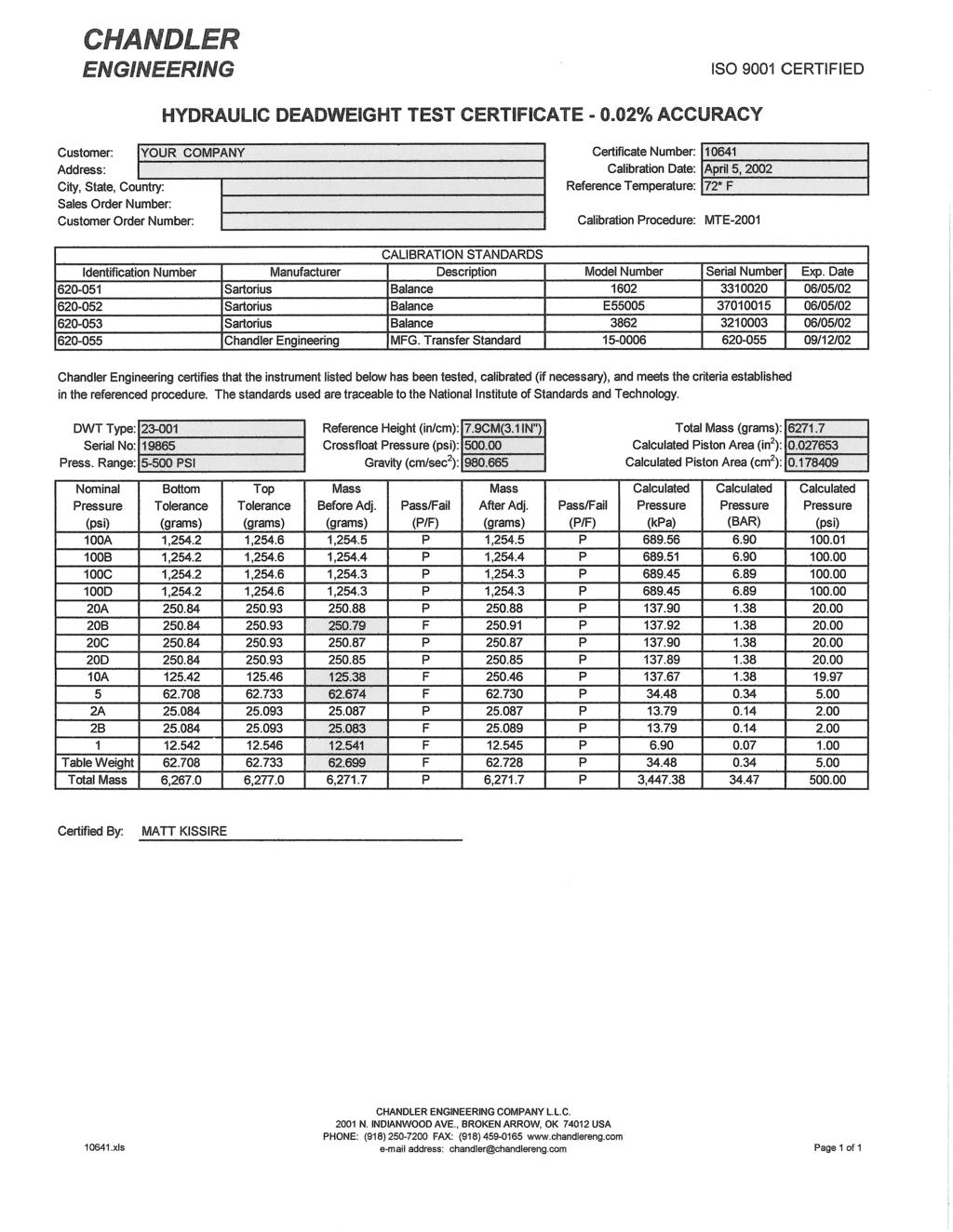
5 Description of Instrument General Information PREFACE P-1 Deadweight Testers are the basic primary standard for the accurate measurement of pressure. Chandler Testers are used to measure the pressure exerted by a gas or liquid and can also generate a test pressure for the calibration of pressure gauges, electronic pressure calibrators, transducers, transmitters, recorders, etc. No other device can match the stability, repeatability and accuracy of the Deadweight Tester. Measurement Principles The most accurate instrument available for measurement of pressures above the range where manometers may be used is the Deadweight Tester. This type of tester operates on the principle of balancing a known mass against the force exerted by an unknown pressure on a piston of a known area. When an exact balance is achieved, the unknown pressure P is equal to mass M of the weights divided by the area A of the piston, according to the formula P = M/A. Tester Accuracy A Certificate of Calibration accompanies every new instrument, verifying that its accuracy will be 0.05% of reading or better. An optional certificate can be furnished when a 0.02% accuracy is required. A typical certificate is found in the Reference Section.
6 P-2 PREFACE Tester Models Numerous models are available to meet specific applications. Pressure ranges of the instruments vary from 3 to 400 psi, 50 to 15,000 psi and 100 to 30,000 psi. Dual-range instruments are available. Refer to the illustrations below and the reference guides found in the Appendix of this manual. Model 2-1 Deadweight Tester Model 5-1 Deadweight Gauge Model 15-1 Deadweight Gauge Model Weight Case Model 23-1 Deadweight Tester
7 PREFACE P-3 Model 55-1, Deadweight Tester Model , , Precision Pressure Standard (PPS) Model 59-1 Featherweight Gauge Model 61-1, Featherweight Gauge
8 P-4 PREFACE Dual-Range Testers Dual-range Testers have interchangeable pistons and cylinder assemblies. The operator can change the assembly quickly, converting the range of the instrument. Dual-range instruments are calibrated in PSIG or in Metric (SI) Units. Pistons in the dual-range units generally have an area ratio of 5:1, meaning that maximum pressure for the tester is five times the pressure selected for the low range. Their weights are common. The weights are double-stamped; the smaller number representing the pressure produced on the low pressure piston. Tester Components and Accessories A typical Deadweight Tester consists of the same components comprising a Deadweight Gauge, in addition to a hand-operated, self-contained pump for the generation of pressure. Included are a piston, cylinder, table, weights, associated plumbing, and an oil reservoir. Tester components are mounted on a base and are protected by a carrying case. Connecting adapters, pointer drivers and a hand jack (for working on gauges) accompany each instrument. Tester specifications and lists of replacement parts are provided for the specific instruments described by this manual. Motor Drive Accessory To achieve optimum sensitivity, friction between the piston and the cylinder of the tester must be minimized while these parts are sliding vertically to indicate a pressure/weight imbalance. If the piston is slowly rotated, frictional forces are reduced, and balance sensitivity is increased. Normally, rotation of the piston is initiated by hand. (For optimum sensitivity, a slow, consistent rotation of the table is desired. The consistency is achieved with Model 58 by connecting a fractional horsepower electric motor and flexible drive, which contribute negligible vertical force to the spinning weights. The motor is driven by 115 volt, 50/60 Hz power. A transformer is furnished when the voltage is 230 volts.) Tripod Accessory Optional Tripods are available as supports for testers in the field. Order Chandler p/n
9 Oil-water Separators PREFACE P-5 Model : Oil-Water Separator is rated for 10,000 psi (69,000 kpa). It is similar to the Model and is supplied complete with valves and stainless steel tubing. Model : Oil-Water Separator used with any Chandler Deadweight Gauge or Tester. It is rated for 5,000 psi (34,500 kpa) and is a stand-alone unit. It comes complete with inlet valve, outlet valve, drain valve, and 10 feet of 1/8" diameter stainless steel tubing to connect it to the deadweight instrument. Model : The Oil-Water separator is rated for a Pressure of 5,000 psi (34,500 kpa) and is designed for use with the Model and Model Deadweight Testers. It will fit inside the tester case for transportation. Model : Oil-Water Separator specifically designed for use with the Model Deadweight Tester. It can be mounted on the side of the tester case for transportation. The pressure rating is 6000 psi (41400 kpa). See SL 66 in Reference Section of this manual for pictorial view of the above describe options.
10 P-6 PREFACE Instrument Specification Sheet Specification Value Maximum Pressure: Up to 30,000 psi (or 206.8MPa) depending on range. Minimum Pressure: Accuracy: Certificate of Calibration: Calibration Temperature: 3 to 50 psi depending on range (table must be spinning to achieve indicated pressure). 0.05% of indicated pressure (optional 0.02% of indicated pressure). Accuracy 0.05%. Optional 0.02% Certificate available upon request. See calibration sheet for oil temperature at which your instrument was calibrated. Gravity: Calibration based on standard gravity of cm/sec 2 Calibration may be referenced to user specified gravity (Contact Chandler Engineering) Recommended Operating Range: Humidity: Vibration: Environment: Typical Shipping weight: Piston Material: Pressure Tubing Material: Weight Materials: Pressurizing Fluid: Input Connector: Seal Material: Carrying Case: 40 to 120 F (4 to 48 C) 0 to 95% RH Small amplitude, high frequency only. Minimize dust and corrosive atmosphere 50 lb (18 kg) to 250 lb (115 kg) depending on pressure range Model 58, 120 lb (58 kg) to 325 lb (146 kg) depending on range Hardened stainless steel Stainless steel Brass or stainless steel Hyrdraulic oil (Chandler p/n ), standard (Chandler p/n P-1169 synthetic oil optional for special requirements) 1/4 in. NPT Buna-N (other materials available Contact Chandler Engineering) Metal case with handles. Accuracy of Chandler Engineering Deadweight Instruments 1. All Chandler Engineering Deadweight instruments are calibrated with traceability to a National Institute of Standards and Technology (NIST). Pressure standards are referenced on the certificate supplied with the instrument. 2. The instrument calibrations performed for temperature are based on Standard Gravity cm/sec 2. The temperature and pressure coefficients are found on the certification sheet supplied with each deadweight instrument.
11 PREFACE P-7 3. If accuracy greater than 0.05% is desired, a Certificate of Calibration is furnished. If the "actual psi" values on the certificate are used, the instrument will have an accuracy of 0.05% or better. Reference the equations for correcting for the effects of temperature, pressure, buoyancy and elevation. Correction Equations for use with Deadweight Testers If a deadweight gage tester is to be used in work for which an accuracy of 0.05% is adequate, then the nominal pressure (sum of the mass values loading the piston) may be taken as the correct pressure. A deadweight tester is capable of measuring pressures with much higher accuracy, provided the user applies corrections for the errors inherent in the device. The deadweight tester supplied by Chandler Engineering provides pressures that are referenced to standard gravity ( cm/sec 2 ) at ambient oil temperature. In most cases, standard gravity should be used, eliminating the need to correct for local gravity. The output pressure from the deadweight tester is affected by a difference in local gravity as compared to standard gravity. Similarly, the effects of buoyancy, ambient temperature, elevation of the transducer relative to the piston, and the pressure effect on the piston effective area must be considered. Use the following equations to apply correction factors to the pressure output for different ambient temperatures, output pressures, and reference elevations. 1 M app Pcorr = ( F gravity F buoyancy F temp F press ) ± P 1000 Acyl F P buoyancy head = D = F press F F temp gravity =1 - D D oil air mass (H - H 1 1+ bp = 1+( a G = Gs cyl + a ref 1 ) piston )(T - T ref ) head
12 P-8 PREFACE where, M app = total of the masses from the test certificate, grams A cyl = piston area at reference temperature and pressure, cm 2 G = local gravity, cm/sec 2 G s = standard gravity, cm/sec 2 D air = density of air at reference temperature and pressure, gram/cm 3 D air = gm/cm 3 at 25 C and atmospheric pressure D mass = density of mass weights, gram/cm 3 D mass = 8.39 gm/cm 3 (unless specified otherwise) D oil = density of oil, gm/cm 3 D oil = 0.83 gm/cm 3 (unless specified otherwise) a cyl = thermal expansion coefficient of the cylinder, 1/ C a piston = thermal expansion coefficient of the piston, 1/ C a cyl + a piston = 2.59 x / C (unless specified otherwise) T = ambient temperature, C T ref = reference temperature (see calibration sheet for temperature, provided with instrument) b = pressure coefficient of the effective area, cm 2 /kg b = 9.39 x 10⁻⁷ cm 2 /kg (unless specified otherwise) P = nominal pressure, kg/cm 2 H = transducer elevation above or below the base plate, cm H ref = distance from the top of the base plate to the bottom of the piston, cm (with piston level between scribed lines) Example of Use of the Deadweight Formulas An operator wishes to check a transducer calibration with a pressure source accuracy of 0.02% referenced to local gravity instead of standard gravity. The calibration is to be performed at Peoria, Illinois, with a tester temperature of 27 C(80.6 F), at an indicated pressure of 17.6 kg/cm 2 (250 psi). The transducer is located 7.62 cm (3 in) above the base plate of a Model 5-1 tester. The operator finds, from the U.S. Coast and Geodetic Survey, that the value of local gravity is cm/sec 2. The piston area listed on the test certificate is cm 2 ( in 2 ) He uses the following weights, with their respective masses, obtained from the test certificate: Nominal Pressure, P (psi) Mass, M app (grams) A B Piston psi (17.6 kg/cm 2 ) grams
13 PREFACE P-9 Using the formulas, F gravity = = P head = (0.83)( ) = kg cm 2 F press = 1 + (9.39E 1-07)( 17.6 = ) F buoyancy = = P ( )( )( )( ) kg cm corr = = Note that all previous calculations are performed using metric units. The following table will assist users in converting the results into other units of pressure. 2 Piston Height above the top of the Base plate Model Numbers Height, cm Height, in 5-1, 55-1, , , Pressure Conversion Factors From to Multiply by kg/cm 2 psi kg/cm 2 kpa (kn/m 2 ) kg/cm 2 Bar kg/cm 2 Dynes/cm kg/cm 2 N/cm psi kpa (kn/m 2 ) psi Bar kpa Bar 0.01
14 P-10 PREFACE GAUGE UNDER TEST WEIGHT OIL RESERVOIR PUMP TABLE PISTON & CYLINDER SUCTION VALVE DISCHARGE VALVE Basic Hydraulic Schematic of a Typical Deadweight Tester
15 Section 1 - Quick Start Unpacking the Deadweight Tester SECTION 1 - QUICK START 1-1 The Chandler Engineering Deadweight Tester or Gauge and its accessories were tested and inspected before the unit was shipped from Chandler Engineering. Carefully uncrate and inspect the instrument and its accessories. If the unit is received in a damaged condition, immediately notify Chandler Engineering in writing, and file a claim with the carrier. Where to Find Help In the event of problems, the local sales representatives will be able to help or the personnel at Chandler Engineering can be contacted. Telephone number: Fax number: address: chandler@chandlereng.com Website: Tools/Equipment Required High pressure tubing (must be rated for use at the maximum pressure of the instrument) Suitable high pressure fittings or adapter fittings (must be rated for use at the maximum pressure of the instrument) Adjustable wrench or suitable open-end wrench A supply of proper oil Safety Requirements Read and observe the following precautions: Do not attempt to substitute common pipe fittings in place of original high pressure fittings used in the plumbing systems on these instruments. Common pipe fittings are not rated for high operating pressure used in these instruments, and the use of such fittings will void the warranty and may create a potentially dangerous condition. Use OEM fittings listed in the replacement parts section of this manual, available through Chandler Engineering. Always wear safety glasses when operating instrument. A high pressure oil leak can cause permanent eye damage. Do not attempt to operate the instrument in excess of the maximum pressure noted on the instrument. Before a dual-range tester is operated, verification of the device's pressure range is essential. Caution labels are attached to the instrument. These must be followed for operator safety.
16 1-2 SECTION 1 - QUICK START "NO SMOKING" signs are to be displayed in laboratories and on laboratory doorways whenever testers are being used for instrument calibration. Because a leak in the tester's high-pressure line can release an explosive mist of oil, proper fire extinguishers should be immediately available. Pre-load the tester's piston with weights before applying pressure to the gauge. Otherwise, shock from the pressure can dislodge the piston retainer ring, allowing the piston to fly out of the tester at high velocity. The operator could be seriously injured if standing directly over the instrument. Spinning the table counterclockwise and failing to load the table with weights before introducing pressure into the instrument can cause the Table to spin off on some models, and the pressure nut to blow off, allowing the piston to become a dangerous projectile. When a tester is used to test a gas or liquid line pressure, connecting tubing and fittings should be rated at a pressure that is higher than the line pressure. If the test fluid or gas (oxygen) will be reactive with the oil in the tester's reservoir, testing must be performed with an instrument supplied with P-1169 synthetic oil. Before hydraulic oil is replaced with part P-1169, the tester must be thoroughly cleaned, and the seals should be replaced to insure proper cleaning. Before bleeding pressure from the tester, the valve at the pressure source should be closed. The instrument's pressure should then be slowly bled to atmosphere. If a vent valve is unavailable, the fitting at the tester should be carefully and slowly loosened. This procedure is to create a small leak, minimizing the volume of oil that will enter the interconnecting tubing. Hydraulic Fluid, such as: Shock absorber, brake fluid, or transmission fluid may not be substituted for the hydraulic oil specified for the instrument. Note: Only approved oils are to be used as tester oils: Chandler p/n Hydraulic Oil, or equivalent, and Chandler p/n P-1169 Synthetic Oil. Setting Up and Operating the Deadweight Tester Procedure for Calibrating a Gauge 1. Position instrument on table. The weight table of the Deadweight Tester must be level and stable before a gauge is calibrated with the tester. A level is mounted on the tester's base plate for leveling the instrument. 2. Remove the carrying case cover, weight rods, and weights from the tester's base. 3. Fill reservoir with oil.
17 SECTION 1 - QUICK START Connect the gauge to be calibrated to the tester, using one of the adapters supplied with the tester. 5. Apply pressure. Close the suction line valve, open the discharge valve, and use the handoperated oil pump to generate pressure applied to both the piston and the gauge being calibrated. 6. Float the table. When the table, while loaded with appropriate weights, "floats" while being rotated, the known pressure is being applied to the gauge being calibrated, and its indication or dial can be observed. Note: Maintain pressure by keeping the guide rod positioned between the two scribe marks on the guide rod, increasing or decreasing pressure as necessary. 7. If the reading of the gauge being calibrated is in error, the gauge can be adjusted while pressure is still applied from the tester.
18 1-4 SECTION 1 - QUICK START This page is intentionally left blank.
19 Section 2 - Operating Instructions Operating Instructions SECTION 2 - OPERATING INSTRUCTIONS 2-1 An illustration showing an assembly of a Model 2-1 tester is shown below: Model 2-1 Deadweight Tester Procedure for Calibrating the Gauge The weight table of the Deadweight Tester must be level and stable before a gauge is calibrated with the tester (or if the tester is used as a gauge to determine an unknown pressure). A level is mounted on the tester's base plate for leveling the instrument. In the field, a tripod provides a stable support for the device. After the carrying case cover, weight rods, and weights are removed from the tester's base, the gauge to be calibrated is connected to the tester, using one of the adapters supplied with the tester. When the gauge is connected to the tester, the gauge becomes part of the tester's pressure chamber. To apply pressure, the suction line valve is closed, the discharge valve opened, and the oil pump is hand-operated to generate pressure applied to both the piston and the gauge being calibrated. NOTE: On models using retaining rings: If weight in excess of the expected pressure is not placed on the table, and the ring sustains shock, examine the ring to ensure that it is still tight in its groove. The ring should fit securely and not be
20 2-2 SECTION 2 - OPERATING INSTRUCTIONS easy to turn with the finger. If the ring is removed for piston cleaning or piston and cylinder replacement, the ring should be checked for tightness after it is reinstalled. When the piston, loaded with appropriate weights, "floats" while being rotated, the known pressure is being applied to the gauge being calibrated, and its indication or dial can be observed. If the reading of the gauge being calibrated is in error, the gauge can be adjusted while pressure is still applied from the tester. Adjusting Test Gauges Calibration of this type of instrument will normally consist of removing the pointer from its shaft and then reattaching it to the shaft at the proper indication. Two tools are furnished with the tester to aid in this corrective procedure. One is a hand jack that assists in removal of the pointer from its shaft. The other is a pointer driver that can be used as a drift punch to tap the pointer back onto its shaft without damage to the gauge. NOTE: Both accessories are attached to the base of a new tester. The technician should make certain to store them after their use, using the mounting screws that are provided in the tester's base. Preparing Tester for Transport After the test gauge has been calibrated, the oil in the tester's piston should be pumped back onto the tester's reservoir and the test gauge removed from the tester. Then the weights, weight rods, and tester cover are replaced, preparing the tester for the next job. Using Tester as a Deadweight Gauge When an unknown pressure is to be measured by a tester, the tester's chamber is filled with oil, and the unknown pressure is applied through a valve and a tube or hose and then through the connector that is mounted on the tester's base. The Deadweight Tester measures applied pressures using the same principle as the Deadweight Gauge. The only differences are the parts that comprise the pressure chambers. In either configuration, the external pressure is applied to the bottom of the piston and is balanced by the mass of the weights that are added to the table. Single valve instrument 1. When an unknown pressure is to be measured by a tester, the tester's chamber is filled with oil, and the unknown pressure is applied through a valve and a tube or hose and then through the connector that is mounted on the tester's base. 2. To move oil from the reservoir into the chamber, open the valve by turning the valve handle until the pointed end is facing in the direction of Suction Valve on the pump. The pump handle is turned counterclockwise to pull oil into the pump.
21 SECTION 2 - OPERATING INSTRUCTIONS Turn the valve to the discharge position by turning the pump handle clockwise to force the oil out of the pump and into the pressure chamber. 4. To transfer another pump load of oil, the valve is placed in the suction position, and the process is repeated. 5. When using the Tester to measure unknown pressure, the valve should be closed (center position). 6. After the unknown pressure has been measured by the tester, the oil is returned to the reservoir by reversing this procedure. Two valve instrument 1. When an unknown pressure is to be measured by a tester, the tester's chamber is filled with oil, and the unknown pressure is applied through a valve and a tube or hose and then through the connector that is mounted on the tester's base. 2. To move oil from the reservoir into the chamber, the discharge line valve is closed, and suction line valve is opened. The pump handle is turned counterclockwise to pull oil into the pump. Then, the suction line valve is closed, and discharge line valve is opened. 3. Turn the pump handle clockwise to force the oil out of the pump and into the pressure chamber. 4. To transfer another pump load of oil, the discharge line valve is closed, the suction line valve opened, and the process is repeated. 5. When using the Tester to measure unknown pressure, both valves should be closed. 6. After the unknown pressure has been measured by the tester, the oil is returned to the reservoir by reversing this procedure. Testing Gauges and Pressure Transducers with Air Air or inert gas may be used to calibrate a gauge (or pressure transducer) whenever contamination of the gauge with oil is unacceptable. An adapter is installed in all Models 55 and 61 to ensure that the air or gas from the supply tank and oil from the tester's reservoir are segregated. 1. Screw Reservoir Adapter into connector of tester's base plate. 2. Install the optional manifold (refer to drawing ) consisting of stainless steel tube, tee, valves, and fittings into top of Reservoir Adapter. 3. Pump oil from reservoir to Reservoir Adapter, filling Adapter approximately 1/3 full. Close both pump valves.
22 2-4 SECTION 2 - OPERATING INSTRUCTIONS 4. Attach supply line from tank regulator (refer to drawing ) to manifold tee. 5. Screw gauge to be tested into top of manifold. 6. Place weight on weight table equal to gauge's first increment (number to be read). 7. Open tank's regulator valve to pressure represented by weight on table until piston floats. 8. Read gauge and record error. 9. Repeat procedure for each, next-higher calibration increment on gauge, making certain that additional weight is placed on weight table before regulator is opened farther. 10. Reverse calibration steps after highest reading of gauge is recorded, making certain that regulator is backed off before each weight is removed from table. Use Of Chandler Deadweight Instruments With Water All Chandler Deadweight Instruments can be used with water as the media. Trouble free operation, giving the sensitivity of which the instrument is capable, is assured if a fluid with better lubricity than water is in contact with the piston and cylinder. Chandler s p/n P-1169 inert Synthetic Oil is recommended. This fluid is chemically inert and safe for use with reactive gases. It has twice the density of water and will not emulsify. Alternatively, an oilwater separator accessory can be attached, providing oil is used to lubricate the piston and cylinder. Separators illustrated in Data Sheet SL 66 are shown in the Reference Section of this manual. Typical applications, where the P-1169 Synthetic Oil is advantageously used, follow: 1. Hydrostatic testing, where water is the media supplied to the Deadweight Gauge or Tester; 2. Testing of Indicating Spring Gauges, for use with reactive gases, where it is desired to have a non-combustible fluid contact the gauge. In this case, a new instrument should be ordered "Cleaned for Reactive Gas Service," or if an existing instrument is used, it should be cleaned by the operator, using a suitable cleaning agent.
23 Section 3 - Maintenance Schedule Tools Required SECTION 3 - MAINTENANCE SCHEDULE 3-1 Adjustable wrench or suitable open-end wrenches Snap ring pliers Cleaning and service tips To ensure accuracy of DEADWEIGHTS, care must be taken to: 1. TRANSPORT THE INSTRUMENT WITH THE COVER IN PLACE. If the cover becomes damaged, it should be replaced. 2. Firmly tighten the knurled nut on the weight rod before transport to avoid abrasion of the weights and loss of their mass. 3. If the weights are abraded in transport or are damaged by being dropped, they should be replaced. 4. Clean the weights with a soft brush rather than with a coarse or soiled cloth to avoid altering the mass of the weights. 5. Avoid contaminating the instrument with dust and grit, preventing unnecessary wear of moving parts. Contamination of the oil in the system will accelerate piston and cylinder wear and degrade instrument accuracy. 6. Fill the oil reservoir through the filler cap with Chandler p/n supplied by the factory before an instrument is used for the first time. The oil level must be maintained above the lower end of the cylinder, or the gas will bypass the oil. When field temperatures are extremely cold, fill the reservoir with SAE 10 non-detergent motor oil. Maximum sensitivity of the instrument to pressure requires that the oil be "light" at the time of measurement. 7. For the instrument to be sensitive, the metal-to-metal interface of its piston and cylinder is designed to allow for the minor escape of oil past the piston to minimize friction and lubricate the piston. Therefore, some leakage past the piston is normal and necessary. A moderate escape of oil can be controlled by adding heavier oil. Excessive leakage or "blowing" of oil past the piston indicates excessive wear of the assembly and requires replacement of the assembly. If the model and serial numbers of the instrument are furnished, the piston and cylinder assembly and the weights can be replaced without need for factory calibration. 8. Replace hydraulic oil (do not use brake fluid, shock absorber, or transmission fluid) in the reservoir with Synthetic Oil (p/n P-1169 available from the factory) when the test fluid or gas (oxygen) will be reactive with the hydraulic oil. Before use with oxygen, clean and purge the system, and replace all seals.
24 3-2 SECTION 3 - MAINTENANCE SCHEDULE 9. Ensure that high-pressure fittings of the instrument are tight when operating the instrument indoors. 10. Remove the piston and cylinder for cleaning by unscrewing the adapter nut. If the nut is sealed to the body with an O-Ring, it should only be finger tightened when replaced. Certification procedures The Chandler Engineering deadweight tester or gauge is a precision device that will require periodic re-certification due to wear of the piston area and weights. To re-certify the deadweight, ship the instrument to Chandler Engineering. Trained personnel will repair any damaged components and perform a cross-float with the Chandler Engineering NIST Master deadweight. Once completed, an updated certificate is issued that included the new piston area and the mass of each weight (referenced to standard gravity unless a local gravity is requested). Oil changes Replace the oil if any contamination is suspected. Corrosive contaminants in the oil may damage the piston and cylinder assembly. Maintenance Schedule Action Inspect condition and safety of instrument Change oil Re-certify Time Interval After each use Every 6 months or as necessary Every 1 2 years
25 Section 4 Troubleshooting Guide SECTION 4 - TROUBLESHOOTING GUIDE 4-1 PROBLEM Gas escapes past piston when used to determine unknown gas pressure. REMEDY Insufficient oil in Reservoir Adapter. Shut off and bleed pressure from tester. Pump oil to adapter until reservoir is full. Damaged Cylinder O-Ring. Unscrew cap nut. Remove guide rod and piston. Use wrench to unscrew cylinder adapter. Push cylinder from adapter with pencil and replace O-Ring. Gas bubbles or blows into oil of center reservoir when determining unknown gas pressure. Damaged adapter O-Ring. Unscrew cap nut. Remove guide rod and piston. Use wrench to unscrew cylinder adapter. Push cylinder from adapter with pencil and replace O-Ring. Not sensitive to small weight changes when used to determine unknown gas pressure. Over-tightened cylinder cap nut. Unscrew cap nut. Re-tighten only until snug. Dirty oil. Remove oil. Clean reservoir with solvent. Fill reservoir with clean oil. Damaged Piston. Remove piston & cylinder as per above "Damaged O- Ring" Clean with solvent. If "Binding" is evident, replace with new part Piston and Cylinder Assembly. Cold weather makes standard oil too viscous. Replace standard oil with P-1484, low temperature pourpoint oil. Pressure cannot be maintained when calibrating another pressure gauge. Air is drawn into pump because of insufficient oil in center reservoir. Unscrew Cap and check oil level in reservoir. Add oil if necessary. Damaged cylinder adapter O-Ring. Unscrew cap nut. Remove guide rod and piston. Use wrench to unscrew cylinder adapter. Push cylinder from adapter with pencil and replace O-Ring. Leakage through valve.
26 4-2 SECTION 4 - TROUBLESHOOTING GUIDE PROBLEM Excessive oil leakage at piston. REMEDY Damaged cylinder O-Ring. Replace P-0062 O-Ring. Oil too light. Check and remove fluid in reservoir if it is shock absorber or brake fluid. Replace with Hydraulic Oil (Chandler p/n or equivalent) Worn piston & cylinder assembly. Replace with new part Piston & Cylinder Assembly. Not sensitive and/or inaccurate operation during hydrostatic testing. Water emulsifying with tester oil. Best - Use P-1169 synthetic oil instead of standard mineral oil. Satisfactory - Use part oil water separator.
27 SECTION 5 REPLACEMENT PARTS 5-1 Section 5 - Replacement Parts Part SECTION 5 - REPLACEMENT PARTS 5-1 Description Number Cap, Reservoir X Pump, Cylinder X Assembly, Piston and Cylinder X Assembly, Pump Plunger X X Cover, Carrying Case X X Assembly, Base Unit X Kit, Replacement Seal X Base Plate X Level X X X Body X X Piston and Cylinder Assembly X X Weight, 1 psi X X X X X X X X X Weight, 2 psi X X X X X X X X X Weight, 5 psi X X X X X X X X X Weight, 10 psi X X X X X X X X X Weight, 50 psi X X X X X X X X X Weight, 100 psi X X X X X X X X X Weight, 500 psi X X X X X X X Weight Rod X X X X X X Carrying Case Cover X X X Weight, 1000 psi X X X X X Weight Set, 0.10 psi X X X X Weight, 500 psi X X Weight, 450 psi X X Base Plate X X X Kit, Replacement Seal X X X Body X Weight, 0.1 psi X Weight, 0.2 psi X Weight, 1 psi X Weight, 2 psi X Weight, 10 psi X Weight, 20 psi X Weight, 100 psi X Weight, 0.5 psi X X X Weight, 5 psi X X X Weight 50 psi X X X Tripod X X X X X X X Tripod with Tilting Head X X X X X X X Base, Body Supporting X Assembly, Body X Assembly, Piston and Cylinder X Rod, Weight X X
28 5-2 SECTION 5 REPLACMENT PARTS 5-2 SECTION 5 - REPLACEMENT PARTS Part Description Number Weights, Set of 0.1 psi X X Weight, 1 psi X X Weight, 2 psi X X Weight, 5 psi X X Weight, 10 psi X X Weight, 20 psi X X Weight, 100 psi X X Nut, Weight Rod X X X X X X X X X X Cover, Carrying Case X Stud, Lower X Weight, 500 psi X X Carrying Case X X X X X Base Plate X Kit, Replacement Seal X Cap, Oil Pump X X X X Assembly, Piston and Cylinder X Assembly, Pump Plunger X X X Cylinder Pump X Cap, Reservoir X Handle, Pump Screw X X X X Cover, Carrying Case X Assembly, Base Unit with Pump X Pump Plunger Only X X Base Plate X Gauge Connector X X Oil, Special Hydraulic, Qt. X X X X X X X X X Kit, Replacement Seal X Hose, 1250 psi, 10 foot X X Hose, 5000 psi, 10 foot X X X Adapter, SS Hose X X X X Tubing, 5000 psi, SS, 1/8, 10 foot X X X X X Tubing, 5000 psi, SS, 1/8, 20 foot X X X X X Adapter, ¼ Male x ¼ Female X X Adapter, ¼ MP x ½ FP X X Adapter, ½ Reservoir X X Tubing, psi, SS, 1/8, 10 foot X X X X Tubing, psi, SS, 1/8, 20 foot X X X Hose, Flexible, 50 foot X X X X Body X Base Plate X Gauge Connector X Pump Cylinder X Pump Cap X Pump Screw X Pump Handle X Adapter, ¼ FP to Gauge Connector X
29 SECTION 5 REPLACEMENT PARTS 5-3 SECTION 5 - REPLACEMENT PARTS 5-3 Part Description Number Adapter, ½ FP to Gauge Connector X Rod, Weight X X X X Assembly, Piston and Cylinder X X X X Nipple, Oil Reservoir X Tube, Body to Gauge Connector X Retainer, Valve Bonnet X Kit, Replacement Seal X Plate, Name X X X X X X X X X X Plate, Serial X X X X X X X X X X X Assembly, Pump Plunger X Ring, Backup X Assembly, Piston Pulley X Assembly, Piston and Cylinder X X X Assembly, Piston and Cylinder X X X Kit, Replacement Seal X Body X X X X X X X Assembly, Piston and Cylinder X X X X X X X X Base X Body X Assembly, Cover X X X Assembly, Piston and Cylinder X X Case, Base Weight X X X Assembly, Weight Case (less weights) X X X Assembly, Piston and Cylinder X Kit, Replacement Seal X Body X X Base Plate X X Pump Cylinder X X Gauge Connector X X Reservoir Connector X X Assembly, Cover, Case X X Kit, Replacement Seal X X C09539 Handle Loop X X X X X X X P-0060 O-Ring, Nylon Swivel X X X P-0062 O-Ring, Cylinder (included in Kit) X X X X X X X X P-0063 O-Ring, Cylinder and Pump X X X P-0065 O-Ring, Pump Cylinder X P-0066 O-Ring, Cylinder Nut X X X X X P-0067 O-Ring, Gauge Connector X P-0070 O-Ring, Piston (included in Kit) X X X X X P-0087 Belt, Pulley X P-0092 Gasket, Filler Plug X P-0093 Gasket, Lower Spud X P-0167 Plug, Filler X P-0179 Adapter, 1/8MP x 9/16-18 X X
30 5-4 SECTION 5 REPLACEMENT PARTS 5-4 SECTION 5 - REPLACEMENT PARTS Part Description Number P-0180 Adapter, Brass, ¼ Hose X X X X X P-0193 Nut, Gland X X X P-0246 Elbow, 1/8 FP X P-0256 Bushing, ½ x ¼ X X P-0291 Valve, 1/8 Male X X P-0530 Pointer Driver X X X X X X P-0531 Hand Jack X X X X X X X P-0535 Tripod X X X P-0655 Screw, Leveling X X X X P-0683 Cap, Plastic X X X X P-0709 Valve, Suction and Discharge X P-0748 Ring, Pump Backup X X P-0760 Plug, Filler X X X P-0791 Stud, Small Weight X X P-0852 Pin, Roll, Pump Screw and Handle X P-0855 Collar, ¼ Tube X X P-0859 Cup, Pump U X X P-0861 Ball, Pump Handle X P-0905 Handle, Leather X X X X X X P-0907 Gasket, Plastic Cap X X X X P-0913 Handle Loop X X X X X X P-0915 Plug, H.P. X P-0927 Plug, Filler, Oil Reservoir X P-0972 Plug, ¼ Pipe X X X P-0981 Gasket, Pump Cylinder X X P-0984 Level, Bull s-eye X X X X X X X X X X P-1009 Retaining Ring X X X X P-1011 Seal, ¼ NPT X P-1012 Seal, ½ NPT X P-1036 U Cap, Pump X X X X P-1038 Ring, Piston Stop X X P-1059 Reducer, ¼ Tube x 1/8 FP X P-1087 Reducer, ¼ Tube x ¼ FP X P-1091 Dust Cover P-1109 Handle X X X X X P-1110 Catch X X X P-1111 O-Ring, Cylinder X X X P-1112 O-Ring, Cylinder Nut X X X P-1119 Seal, 1/8 NPT X X P-1120 Nut, Knurled, Small Weights X X X P-1121 Stud, Small Weight X X X X X X X X P-1407 Thrust Bearing X P-1415 Valve, Outlet Discharge X X P-1416 Tube Connector, 1/8 T x 1/8 MP X X P-1477 Elbow, 1/8 MP X X P-1478 Oil Reservoir X X X
31 SECTION 5 REPLACEMENT PARTS 5-5 SECTION 5 - REPLACEMENT PARTS 5-5 Part Description Number P-1479 Oil Reservoir X P-1480 Nipple, Hex, SS, ¼ MP X P-1506 Valve, Reservoir Suction, 1/8 FP X P-1545 Reducer, ¼ Tube x ½ FP X P-2192 Valve, Suction X P-2199 Valve, Pressure, 3-Way X
32 5-6 SECTION 5 REPLACEMENT PARTS This page is intentionally left blank. 5-6 SECTION 5 - REPLACEMENT PARTS
33 SECTION 6 DRAWINGS AND SCHEMATICS 6-1 Section 6 - Drawings and Schematics Part Number Description Assembly - High Pressure Deadweight Tester Schematic Oil-Water Separator Assembly High Pressure Deadweight Gauge Assembly Super Pressure Deadweight Gauge Assembly Hyper Pressure Deadweight Gauge Tripod Assembly Assembly Standard Deadweight Gauge Assembly Carrying Case Assembly Standard Deadweight Tester Schematic Testing Gauge with Water B Assembly Super Pressure Tester Brass Weights S Assembly Super Pressure Tester Stainless Weights Assembly Precision Pressure Standard (PPS) Assembly Precision Pressure Standard (PPS) Dual Hyper Assembly Precision Pressure Standard (PPS) Dual Hyper Assembly Featherweight Gauge Assembly Weight Case Assembly Featherweight Tester Assembly Featherweight Tester
34
35
36
37
38
39
40
41
42
43
44
45
46
47
48
49
50
51
52
53
54
55
56 APPENDIX A-1 Standard Deadweight Tester - Series 23 and 02 Select the desired units and then the code number defining the instrument with the desired range and smallest weight STANDARD PRESSURE (Under 2000 psi or 14,100 kpa) Minimum Maximum Code Smallest Weight Pressure Pressure Units 0.1 psi 1 psi 001 H N psi 001 J P K Q L R kpa 10 kpa 145 H N kpa 145 J P K Q L R HIGH PRESSURE SERIES (Under 5,000 psi or 36,100 kpa) Minimum Maximum Code Smallest Weight Pressure Pressure Units 0.1 psi 1 psi 001 H N J P psi 001 K Q kpa 10 kpa 145 H N J P kpa 145 K Q kg/cm kg/cm H N J P kg/cm K Q MATERIALS FOR WEIGHTS B - Brass S - Stainless Steel FILL FLUID T - TYPE Special Hydraulic Oil For Normal Use O - Type P-1169 Synthetic Oil For Use with Oxygen XX -XXXX - X - X EXAMPLE: R - B - T
57 A-2 APPENDIX Standard Deadweight Tester - Series SUPER PRESSURE (Under 20,000 psi) Minimum Maximum Code Smallest Weight Pressure Pressure Units 0.1 psi 1 psi 100 H N J P K Q psi 150 N kpa 10 kpa 145 H N J P kpa 145 K Q kg/cm kg/cm H N J P kg/cm K Q MATERIALS FOR WEIGHTS B - Brass S - Stainless Steel FILL FLUID T - TYPE Special Hydraulic Oil For Normal Use O - Type P-1169 Synthetic Oil For Use with Oxygen 55 - XXXX - X - X EXAMPLE: P - B - T
58 APPENDIX A-3 Standard Deadweight Dual Range Tester - Series 02 & HIGH PRESSURE DUAL RANGE TESTER Low Range High Range Code Smallest Weight Minimum Maximum Minimum Maximum Units 0.1psi 1psi 070 H N J P psi 070 K Q kg/cm 2 0.1kg/cm H N J P kg/cm K Q kpa 10kPa 195 H N J P kpa 195 K Q SUPER PRESSURE DUAL RANGE TESTER Low Range High Range Code Smallest Weight Minimum Maximum Minimum Maximum Units 0.01 psi 1 psi 060 H N J P psi 060 K Q kg/cm kg/cm H N J P kg/cm K Q kpa 10 kpa 165 H N J P kpa 165 K Q Dual Range Testers have interchangeable piston and cylinder pairs. The assembly can be changed very quickly to convert the range. MATERIALS FOR WEIGHTS B - Brass S - Stainless Steel FILL FLUID T - Type Special Hydraulic Oil For Normal Use O - Type P-1169 Synthetic Oil For Use With Oxygen XX - XXXX - XX - X Example: H - B - T
59 A-4 APPENDIX Featherweight Tester - Series 61 Select the desired units and then the code number defining the instrument with the desired range and the smallest weight. Minimum Maximum Code Smallest Weight Pressure Pressure Units 0.1 psi 1 psi 030 H N J P K Q psi 030 L R H N J P K Q L R kpa 10 kpa 155 H J K kpa 155 L M H N K P L Q M R kg/cm kg/cm H J K kg/cm L M H N J P K Q L R MATERIALS FOR WEIGHTS B - Brass S - Stainless Steel FILL FLUID T - Type Special Hydraulic Oil for Normal Use O - Type P-1169 Synthetic Oil for Use with Oxygen 61 - XXXX - X - X EXAMPLE: J - B - T
60 APPENDIX A-5 Featherweight Dual Range Tester - Series 61 Dual Range Testers have interchangeable piston and cylinder pairs. The assembly can be changed very quickly to convert the range. Select the desired units and then the code number defining the instrument with the desired range and smallest weight. Smallest Low Range High Range Code Weight Minimum Maximum Minimum Maximum Units 0.1 psi 060 H J K psi 060 L kpa 165 H J K kpa 165 L kg/cm H J K kg/cm L MATERIALS FOR WEIGHTS B - Brass S - Stainless FILL FLUID T - Type Special Hydraulic Oil for Normal Use O- Type P-1169 Synthetic Oil for Use with Oxygen 61 - XXXX - X - X EXAMPLE: K - B T
61 A-6 APPENDIX Featherweight Motor-Driven Tester - Series 61 To achieve optimum sensitivity and repeatability at low pressures, friction between the piston and cylinder must be minimized. This can be achieved by using an electric motor with a flexible drive. Select the desired units and then the code number defining the instrument with the desired range and smallest weight. Minimum Maximum Code Smallest Weight Pressure Pressure Units 0.1 psi 1 psi 035 H J K L psi 025 H N J P K Q L R MATERIALS FOR WEIGHTS B - Brass S - Stainless Steel FILL FLUID T - Type Special Hydraulic Oil for Normal Use O - Type P-1169 Synthetic Oil for Use with Oxygen OPERATING VOLTAGE AND FREQUENCY 6-120V, 60 Hz AC 5-220V, 50 Hz AC 61 - XXXX - X - X - X EXAMPLE: J - B - T 6
62 APPENDIX A-7 Precision Pressure Standard Tester - Series 58 Select the desired units and then the code number defining the instrument with the desired range and smallest weight. Stainless Minimum Maximum Smallest Brass Weights Steel Weights Pressure Pressure Weight Units 050H 197H J 197J K 197K psi 001H 198H J 198J K 198K H 151H H 301H H 191H J 191J K 191K kpa 145H 192H J 192J K 192K H 266H H 194H J 194J K 194K kg/cm 2 080H 195H J 195J K 195K H 281H FILL FLUID T - Type Special Hydraulic Oil For Normal Use O - Type P-1169 Synthetic Oil For Use With Oxygen AC Voltage For Motor 1 - For 120VAC, 50 or 60 Hz Power 5 - For 220VAC, 50 or 60 Hz Power 58 - XXXX - X - X EXAMPLE: J - T 1
63 A-8 APPENDIX Precision Pressure Standard Tester - Series 58 Dual Range Testers Select the desired units and then the code number defining the instrument with the desired range and smallest weight. Stainless Minimum Maximum Smallest Brass Weights Steel Weights Pressure Pressure Weight Units 060H 199H 10/ / J 199J 10/ / K 199K 10/ / psi 200H 201H 10/ / H 193H 100/ / J 193J 100/ / kpa 165K 193K 100/ / H 206H 100/ / H 196H 1/ / J 196J 1/ / kg/cm 2 090K 196K 1/ / H 211H 1/ / FILL FLUID T - Type Special Hydraulic Oil For Normal Use O - Type P-1169 Synthetic Oil For Use With Oxygen AC Voltage For Motor 1 - For 120VAC, 50 or 60 Hz Power 5 - For 220VAC, 50 or 60 Hz Power 58 - XXXX- X - X EXAMPLE: J - T - 1
64
65
66
67


68 Deadweight Testers PRIMARY STANDARD Deadweight Testers are the basic primary standard for the accurate measurement of pressure. Chandler Testers are used to measure the pressure exerted by a gas or liquid and can also generate a test pressure for the calibration of pressure gauges, electronic pressure calibrators, transducers, transmitters, recorders, etc. No other device can match the stability, repeatability and accuracy of the Deadweight Tester. HIGH SENSITIVITY When the weights are applied to the piston, the entire assembly is rotated slowly. This rotation minimizes frictional effects and permits vertical motion of the piston with extremely small variations in pressure. Measurements to 1/10 psi (1 kpa) can be made. OPERATION The Chandler Engineering Deadweight Tester utilizes the well proven piston system consisting of a vertically mounted precision lapped stainless steel piston and sleeve with a metal to metal seal. This superior design eliminates friction and oil leakage created by o-ring seals used in lower cost testers. A bubble level and adjustable feet are provided to enable the operator to level the instrument. HIGH ACCURACY Deadweight Testers blend ruggedness with high accuracy. Variations over time typical of strain gauges or spring gauges are eliminated. Their operation depends only on balancing known weights against the force exerted by an unknown pressure acting on a piston of precisely known area. The weights are applied manually until the piston is floating with no net vertical movement. Each piston s area is determined by comparison against a piston of known area traceable to the National Institute of Standards and Technology. The mass of the balancing weights is also traceable to NIST. FEATURES 3 Accurate % of indicated pressure, traceable to the National Institute of Standards and Technology (NIST), 0.02% available 3 Reliable - hardened stainless steel pistons and corrosion resistant materials. 3 Screw Pump - allows fine pressure adjustments 3 Certificate of Calibration 3 Gas or Liquid pressure measurement 3 Repair Service - spare parts available North Indianwood Avenue, Broken Arrow, OK Phone: Fax: , by AMETEK, Inc. All rights reserved. chandler.sales@ametek.com www. chandlereng.com AEROSPACE & DEFENSE
 Humidity: 0 to 95% RH Vibration: Small amplitude, high frequency only Environment: Minimize dust and corrosive")

69 General Specifications Accuracy: 0.05% of indicated pressure Certificate of Calibration: Furnished for 0.05% Calibration Temperature: 77 F (25 C) Calibration based on std gravity of Calibration Meets: MIL-C-45662A Temperature Limit: 40 to 120 F (4 to 50 C) Humidity: 0 to 95% RH Vibration: Small amplitude, high frequency only Environment: Minimize dust and corrosive atmosphere Piston Material: Hardened Stainless Steel Pressure Tubing Material: Stainless Steel Weight Material: Brass Fill Fluid: Non-toxic ISO Grade 68 Premium Oil, standard. Synthetic fluid optional Options Stainless Steel Weights Dual Range Piston/Cylinder 0.02% Certificate of Calibration Oxygen Service Cleaning Oil Water Separator Metric Adapters Synthetic Operating Fluid for O2, Water or Steam Service Local Gravity Calibration Furnished with every Deadweight Carrying Case with Instruction Manual Set of Weights Operating Fluid Gauge Pointer Remover Gauge Pointer Driver 1/4 in and 1/2 in NPT adapters Certificate of Calibration for 0.05% accuracy One Year Guarantee Furnished with Precision Pressure STD Tester Vinyl dust Cover in Lieu of Carrying Case Wrench Set Spare-o-rings and Seals Electric Motor to spin Weights Oil-Water Separators Model Rated for pressure of 5,000 psi (34,500 kpa) designed for use with Models and Models Deadweight Testers. Model Rated for pressure of 5,000 psi (34,500kPa) is a stand-alone unit. It can be used with the Chandler Deadweight Gauge or Tester. It come complete with inlet, outlet and drain valves. You will also receive 10 ft of 1/8 in diameter SS tubing for connection. Model Rated for 10,000 psi (69,000 kpa). It is similar to the Model and supplied complete with valves and SS tubing for connection. Model Rated for 6,000 psi (41,400 kpa) designed especially for use with the Model Tester North Indianwood Avenue, Broken Arrow, OK Tel: Fax: chandler.sales@ametek.com Houston Sales and Services 4903 W. Sam Houston Parkway, N., Suite A-400, Houston, TX Tel: Fax: Printed in the U.S.A. 2008, by AMETEK, Inc. All rights reserved. XM808PDF (360000)
70
Refinery Supply Company, Inc.
 Refinery Supply Company, Inc. OPERATING INSTRUCTIONS Super Pressure Dead Weight Tester Catalog No. 35260 Serving the Oil & Gas Industry since 1923 9133-A East 46th Street Tulsa, Oklahoma 74145-4823 Voice
Hydraulic Deadweight Tester Model CPB5800
 Calibration technology Hydraulic Deadweight Tester Model CPB5800 Applications Primary standard for ranges up to 20,000 psi hydraulic Pressure reference / calibration standard used in production and calibration
Pressure balance Differential pressure version Model CPB5600DP
 Calibration technology Pressure balance Differential version Model CPB5600DP WIKA data sheet CT 31.56 for further approvals see page 7 Applications Primary standard for the calibration of differential
2311FA. Pressure Tester USER INSTRUCTION MANUAL BARFIELD M/N 2311FA Revision C April 12, 2011 BARFIELD, INC. Corporate Headquarters
 2311FA Pressure Tester USER INSTRUCTION MANUAL BARFIELD M/N 2311FA 56-101-00212 Revision C April 12, 2011 BARFIELD, INC. Corporate Headquarters 4101 Northwest 29th Street Miami, Florida 33142 www.barfieldinc.com
Parts List. Item # Part # # Reqd. Description
 5.2017.6.f 1 3800 Series Injector 1 2 3 4 5 6 7 21 8 9 20 10 11 12 19 18 17 16 15 14 13 Parts List Item # Part # # Reqd. Description 1 A-0664 1 5 Gallon 430 Reservoir 2 A-0575 1 Thumb Screw 3 A-0172 1
INSTRUCTION MANUAL MODEL 1200 ATMOSPHERIC CONSISTOMETER
 INSTRUCTION MANUAL MODEL 1200 ATMOSPHERIC CONSISTOMETER Revision L November 2015 P/N: 12-0185 S/N: 2001 N. Indianwood Ave Broken Arrow, Oklahoma 74012 U.S.A. Telephone: 918-250-7200 Fax: 918-459-0165 E-mail:
6200 Series. Specifications. Fluid End Power End Models 6211, 6212, 6221, & 6222 Models 6241 & 6242 Part Material Part Material Part Material
 5.2018.12.i 6200 Series Specifications The Flomore 6200 Series Pump line consists of a series of basic pump options all developed from a modular power unit. All units are pneumatically driven positive
ACHL Series Pump. Operation and Maintenance Manual Air Driven, Hand Operated High Pressure Liquid Pump
 ACHL Series Pump Operation and Maintenance Manual Air Driven, Hand Operated High Pressure Liquid Pump Catalog: 02-9245ME February 2013 Model # Serial # Drawing # Order # Mfg. Date Table of Contents page
MA-5200 Series MA-5300 Series
 MA-5200 Series MA-5300 Series Two-Position Actuators General Instructions Application The MA-5200 series and MA-5300 series actuators are used for two-position control of valves and dampers which require
Service Jacks. Operating Instructions & Parts Manual. Model Number. Capacity 4 Ton 4 Ton Air/ Manual 10 Ton 10 Ton Air/ Manual HW93657/ HW93660
 Service Jacks Operating Instructions & Parts Manual Model Number HW93657 HW93667 HW93660 HW93662 Capacity 4 Ton 4 Ton Air/ Manual 10 Ton 10 Ton Air/ Manual Made in North America HW93657/ HW93660 HW93667/
Model Ton Hand Carry Axle Jack P/N: CJ67D0250-1
 Model 1504-50 15 Ton Hand Carry Axle Jack P/N: CJ67D0250-1 Operation and Maintenance Manual with Illustrated Parts List 2222 South Third Street Columbus, Ohio 43207-2402 Phone (614) 443-7492 FAX (614)
MODEL G300 BRAKE BLEEDER
 MODEL G300 BRAKE BLEEDER Installation, Operation & Repair Parts Information Branick Industries, Inc. 4245 Main Avenue P.O. Box 1937 Fargo, North Dakota 58103 REV120716 P/N: 81-0035H THIS PAGE INTENTIONALLY
PENBERTHY MODELS GL AND GH GAS OPERATED JET PUMPS INSTALLATION, OPERATION AND MAINTENANCE INSTRUCTIONS
 Before installation, these instructions must be read carefully and understood. PRODUCT WARRANTY Emerson warrants its Penberthy products as designed and manufactured to be free of defects in the material
Pressure Instrument Testing Equipment
 Pressure Instrument Testing Equipment BULLETIN TE-1 A Halliburton Company A Durable, Portable Primary Standard Model 1305D Deadweight Tester The Ashcroft 1305D Deadweight Tester is an affordable, portable
Installation and Operation Manual
 Industrial Process Installation and Operation Manual Advantage Actuator 2.0 Table of Contents Table of Contents Introduction and Safety...2 Safety message levels...2 User health and safety...2 Transportation
HIGH PRESSURE CONTROL VALVE PISTON BALANCED
 PISTON BALANCED All Rights Reserved. All contents of this publication including illustrations are believed to be reliable. And while efforts have been made to ensure their accuracy, they are not to be
Rosemount 402 and 402VP
 Rosemount 402 and 402VP Contacting Conductivity Sensors Instruction Manual LIQ-MAN-402 Rev. M May 2017 hasgkas Essential Instructions Read this page before proceeding! Emerson designs, manufactures and
Table of Contents WARRANTY
 H.E.R.O. Industries a division of Middlefield Bancorp Limited 2719 Lake City Way, Burnaby, B.C., Canada Phone: ( 604 ) 420-6543 Fax: ( 604 ) 420-8725 Toll Free: 1-800-494-4376 E-mail: sales@hero.ca Website:
20 TONNE HYDRAULIC PRESS MODEL NO: CSA20FBT
 20 TONNE HYDRAULIC PRESS MODEL NO: CSA20FBT PART NO: 7614058 OPERATION & MAINTENANCE INSTRUCTIONS WARNING: Read these instructions before using the press GC0516 INTRODUCTION Thank you for purchasing this
INSTALLATION AND SERVICE MANUAL FOR TURBO-CARB HIGH CAPACITY CARBONATOR
 Please refer to the Lancer web site (www.lancercorp.com) for information relating to Lancer Installation and Service Manuals, Instruction Sheets, Technical Bulletins, Service Bulletins, etc. INSTALLATION
Dead-weight tester in compact design Model CPB3800
 Calibration Dead-weight tester in compact design Model CPB3800 WIKA data sheet CT 31.06 for further approvals see page 9 Applications Primary standard for calibrating the scale in a hydraulic range up
Welker Automatic Insertion Diffusing Probe Model AIP-3DP
 Installation, Operation, and Maintenance Manual Welker Automatic Insertion Diffusing Probe Model AIP-3DP The information in this manual has been carefully checked for accuracy and is intended to be used
Instruction Manual. Labnet Spectrafuge 16M Microcentrifuge
 Instruction Manual Labnet Spectrafuge 16M Microcentrifuge Labnet International PO Box 841 Woodbridge, NJ 07095 Phone: 732 417-0700 Fax: 732 417-1750 email: labnet@labnetlink.com Safety Precautions NEVER
F-4600 INLINE ULTRASONIC FLOW METER Installation and Operation Guide
 F-4600 INLINE ULTRASONIC FLOW METER Installation and Operation Guide 11451 Belcher Road South, Largo, FL 33773 USA Tel +1 (727) 447-6140 Fax +1 (727) 442-5699 1054-7 / 34405 www.onicon.com sales@onicon.com
Model Type T Hydraulic Deadweight Tester
 Visit us at www.testequipmentdepot.com p r e s s u r e 99 Washington Street Melrose, MA 02176 Phone 781-665-1400 Toll Free 1-800-517-8431 Model Type T Pressure Range 100 to 10,000 kpa (10 to 15,000 psi)
Hydraulic PTO Flow Device
 Safety, Operation, and Maintenance Manual WARNING Improper use of this tool can result in serious bodily injury This manual contains important information about product function and safety. Please read
INSTRUCTION MANUAL INTERNAL GEAR PUMP TITAN G-4124A SERIES=> FLANGED TITAN G-124A SERIES => FLANGED MODELS:
 INSTRUCTION MANUAL INTERNAL GEAR PUMP TITAN G-4124A SERIES=> FLANGED TITAN G-124A SERIES => FLANGED MODELS: G-H, G-HL, G-K, G-KK, G-L, G-LQ, G-LL, GLS, G-Q, G-QS 1 Contents Maintenance Thrust bearing adjustment
P5510. Users Manual. Pneumatic Comparison Test Pump. Test Equipment Depot Washington Street Melrose, MA TestEquipmentDepot.
 Test Equipment Depot - 800.517.8431-99 Washington Street Melrose, MA 02176 TestEquipmentDepot.com P5510 Pneumatic Comparison Test Pump Users Manual PN 3952297 November 2010 2010 Fluke Corporation. All
Operating and Maintenance Manual for Type S Flowmeters. M101 Rev. B Type S Flowmeters: 5 8, 3 4 and 1 with 157 & 600 Series Registers
 Operating and Maintenance Manual for Type S Flowmeters M101 Rev. B Type S Flowmeters: 5 8, 3 4 and 1 with 157 & 600 Series Registers TABLE OF CONTENTS Installation & Operation... Page 1 Calibration...
Model Type T Hydraulic Deadweight Tester
 p r e s s u r e Model Type T Pressure Range 100 to 10,000 kpa (10 to 15,000 psi) Accuracy to ±0.015% of Indicated reading Accuracy ±0.025 and 0.100% is also available Repeatebility ±0.005% of Indicated
200 Series Flow Meters
 Proteus Industries Inc. 200 Series Flow Meters Technical Reference Manual Can we Improve? Tell our President! Can we improve our product, our support or this manual? We are committed to continuous improvement
Valtek Spring Cylinder Linear Actuators
 Valtek Linear Actuators GENERAL INFORMATION The following instructions are designed to assist in installing, troubleshooting and servicing Valtek spring cylinder actuators. Product users and maintenance
PSR-HP-3000 MANUAL HAND PUMP INTERNAL LIQUID CAPICITY MAXIMUM OUTPUT PRESSURE PsiG (BarG) GALLONS (LITERS) 3000 (207) 5 (19)
 GALLONS (LITERS) 3000 (207) 5 (19)") PAGE 1 OF 6 P-SERIES HAND PUMP OPERATING INSTRUCTIONS WARNING: PRESSURE TESTING IS INHERENTLY DANGEROUS. STRICT ADHERENCE TO THESE OPERATING INSTRUCTIONS AND INDUSTRY SAFETY PRACTICES COULD PREVENT INJURY
PAGE 1 OF 6 P-SERIES HAND PUMP OPERATING INSTRUCTIONS WARNING: PRESSURE TESTING IS INHERENTLY DANGEROUS. STRICT ADHERENCE TO THESE OPERATING INSTRUCTIONS AND INDUSTRY SAFETY PRACTICES COULD PREVENT INJURY
5020 Series Injector
 5.2018.9.k 1 5020 Series Injector 1 2 3 4 5 6 10 11 7 12 13 8 2 14 Parts List 15 16 17 Item # Part # # Reqd. Description Material Alternate Part # 1 A-1854 1 0-12 PSI Pressure Gauge A-1295SS 2 A-0022 1
Industrial Turbo Meters, Sizes 2" through 6"
 Industrial Turbo Meters Sizes 2" through 6" TUR-UM-00530-EN-19 (October 2014) User Manual Industrial Turbo Meters, Sizes 2" through 6" User Manual CONTENTS Scope of the Manual 5 Specifications 5 Product
Purging Air From Divider Block Lubrication Systems
 FROST ENGINEERING SERVICE Purging Air From Lubrication Systems A D I V I S I O N O F G E C S E Y S A L E S & S E R V I C E DESCRIPTION Divider block lubrication systems operate correctly only when all
AXD 530 MicroManometer
 OWNER S MANUAL AXD 530 MicroManometer A TSI Company Table of Contents Features 2 Using the AXD530 Safely 3 Getting Started 4 Installing Batteries 4 Preparing the Instrument 4 Attaching the Optional Pitot-Static
MAINTENANCE MANUAL FOR THERMOSTATIC TEMPERATURE REGULATING VALVE TRAC STYLE P
 MANUAL NUMBER P-EFS-1 MAINTENANCE MANUAL FOR THERMOSTATIC TEMPERATURE REGULATING VALVE TRAC STYLE P TRAC Regulator Company Inc. 160 South Terrace Avenue Mount Vernon, New York USA 10550-2408 Phone: (914)
MicroCoat System Operating Manual MC4000 Series MC785M, MC785M-WF Spray Valves
 MicroCoat System Operating Manual MC Series MC785M, MC785M-WF Spray Valves A NORDSON COMPANY Introduction The MicroCoat System provides precise lubrication control for metal stamping operations. The MC
ONYX VALVE CO MODEL DAO-PFC Installation & Maintenance
 ONYX VALVE CO MODEL DAO-PFC Installation & Maintenance OPERATION: (4-2010) The Onyx DAO-PFC pinch valve is an open frame valve without housing enclosure and fails closed on loss of air. The actuator drives
PRESSURE REGULATOR BACK PRESSURE TO ATMOSPHERE WITH OUTSIDE SUPPLY
 PRESSURE REGULATOR BACK PRESSURE TO ATMOSPHERE WITH OUTSIDE SUPPLY All Rights Reserved. All contents of this publication including illustrations are believed to be reliable. And while efforts have been
NUMBER: S.M. REF.: Listed in Table ENGINE: EPA07 Series 60 DATE: October 2012 SUBJECT: REFERENCES TO THE TURBOCHARGER PURGE ROUTINE
 NUMBER: 10 01 12 S.M. REF.: Listed in Table ENGINE: EPA07 Series 60 DATE: October 2012 SUBJECT: REFERENCES TO THE TURBOCHARGER PURGE ROUTINE ADDITIONS, REVISIONS, OR UPDATES Publication Number Platform
6.0 SPECIFICATIONS CONTENTS. Calibration. According to factory procedureeeeeeeeeeeeeee Accuracy*
 6.0 SPECIFICATIONS Calibration According to factory procedureeeeeeeeeeeeeee Accuracy* ± 1% full scale (FS) or ± 1 graduation on scale Scale diameter 41 mm Temperature range 45 to 115 F (10-45 C) Air humidity
Operation & Service Manual
 Operation & Service Manual Technical Manual Model: 02-7813C0100 12 Ton (10.8 Metric Ton) Two Stage Hydraulic Axle Jack 06/2006 Rev. OR Includes Illustrated Parts List Tronair, Inc. 1740 Eber Road Holland,
Back Pressure Regulator
 Instruction Sheet P/N 108652H Description The Nordson back pressure regulator is a spring-loaded, hand-operated fluid pressure regulator designed for use with general liquid coating materials. The regulator
SERIES 8100 HAND-OPERATED PRESSURE CALIBRATION UNITS
 SERIES 8100 HAND-OPERATED PRESSURE CALIBRATION UNITS PORTABLE PRESSURE SOURCE USED WITH A PRESSURE GAUGE TO FIELD CALIBRATE A VARIETY OF PRESSURE DEVICES, i.e., PRESSURE SWITCHES, GAUGES, DIFFERENTIAL
MP18 Stacking Valve System Technical Information Manual
 Electric Drives and Controls Hydraulics Linear Motion and Assembly Technologies Pneumatics Service MP18 Stacking Valve System Technical Information Manual The Drive & Control Company Copyright 1996 Bosch
ANDERSON GREENWOOD SERIES 500 PILOT OPERATED SAFETY RELIEF VALVES INSTALLATION AND MAINTENANCE INSTRUCTIONS
 Before installation these instructions must be fully read and understood TABLE OF CONTENTS 1. General valve description and start-up... 1 2. Main valve maintenance... 1 3. Pilot maintenance... 5 4. Pilot
KENCO ENGINEERING COMPANY
 KENCO ENGINEERING COMPANY P.O. BOX 470426 TULSA, OK 74147-0426 PHONE: (918) 663-4406 FAX: (918) 663-4480 www.kenco-eng.com e-mail: info@kenco-eng.com SERIES KTD THERMAL DIFFERENTIAL FLOW/LEVEL SWITCH INSTALLATION
Shortening Disposal Unit
 Shortening Disposal Unit (SDU 50, 90, 100 and BKSDU) Installation, Operation, Service and Parts Manual Frymaster, a member of the Commercial Food Equipment Service Association, recommends using CFESA Certified
For additional information, please visit our website at SENSOR SPECIFICATIONS
 Instruction Sheet PN 51A-140/rev.E December 2010 Models 140, 141, and 142 Conductivity Sensors For additional information, please visit our website at www.emersonprocess.com/raihome/liquid/. SENSOR/PROCESS
Split Body Valves with Bellows Seal Series Globe Valves Series Angle Valves Series Way-Valves
 Installation, Operation, Maintenance Instructions Split Body Valves with Bellows Seal Series 025 300 Globe Valves Series 027 300 Angle Valves Series 028 300 3-Way-Valves 1 GENERAL INFORMATION These instructions
MAx-305 & MAx-318 Series MAx-405 Through MAx-419 Series Two-Position Actuators
 MAx-305 & MAx-38 Series MAx-405 Through MAx-49 Series Two-Position Actuators General Instructions Application For two-position operation of dampers, valves, and other equipment which require the return
Series 111 Accumulator Product Information
 Series 111 Accumulator Product Information l Model 111.11 Model 111.12 011-553-304 B Copyright information Trademark information Contact information Publication information 2000 MTS Systems Corporation.
Technical Manual MSI Hydraulic Adjustable Choke
 Technical Manual MSI Hydraulic Adjustable Choke MSI A Division of Dixie Iron Works, Ltd. 300 W. Main St. Alice, TX 78332 www.diwmsi.com (800) 242-0059 Revision A TABLE OF CONTENTS SECTION 1 WARNINGS...
INSTRUCTION MANUAL MODEL 3065 Wettability Tester Revision F January 2016 P/N:
 INSTRUCTION MANUAL MODEL 3065 Wettability Tester Revision F January 2016 P/N: 3065-0009 S/N: 2001 N. Indianwood Ave. Broken Arrow, Oklahoma 74012 U.S.A. Telephone: 918-250-7200 Fax: 918-459-0165 E-mail:
RELEASING PRESSURE IN THE HYDRAULIC SYSTEM,
 Testing And Adjusting Introduction NOTE: For Specifications with illustrations, make reference to SPECIFICATIONS for 225 EXCAVATOR HYDRAULIC SYSTEM, Form No. SENR7734. If the Specifications are not the
Standard Valves Series Globe Valves Series Angle Valves Series Way-Valves
 Installation, Operation, Maintenance Instructions Standard Valves Series 035 000 Globe Valves Series 031 000 Angle Valves Series 033 000 3-Way-Valves 1 GENERAL INFORMATION These instructions are designed
#9040 FUEL TANK SWEEPER
 #9040 FUEL TANK SWEEPER INSTRUCTION MANUAL FILTERS AND REMOVES FINE BIO-CONTAMINANTS, ALGAE, ETC. SWEEPING PROCESS REMOVES LARGE CONTAMINANTS FROM OIL TANKS SUCH AS RUST, WATER, CRUDE AND DIRT CIRCULATES
INSTALLATION/OPERATION/MAINTENANCE INSTRUCTIONS FOR ARCHON MODELS WD2010L, WD2010, WD2010H WASHDOWN STATIONS. ARCHON Industries, Inc.
 ARCHON Industries, Inc. Washdown Stations Models WD2010L, WD2010, WD2010H Installation / Operation / Maintenance Instructions 1 This manual has been prepared as an aid and guide for personnel involved
IMPORTANT!!!! Read this manual before attempting any installation, wiring or operation.
 Industrial Turbo Meters Sizes 2" through 6" Installation & Operation Manual IMPORTANT!!!! Read this manual before attempting any installation, wiring or operation. BadgerMeter,Inc. IOM-003-15 Part No.
Material Specifications
 5.2012.12.b 6200 Series Specifications The Flomore 6200 Series Pump line consists of a series of basic pump options all developed from a modular power unit. All units are pneumatically driven positive
Instruction Manual and Parts List (G323FHF 630M) with Flow Serve Type Q Seal
 with Flow Serve Type Q Seal") TM Instruction Manual and Parts List (G323FHF 630M) with Flow Serve Type Q Seal WARNING This Instruction Manual and General Instructions Manual, CA-1, should be read thoroughly prior to pump installation,
TM Instruction Manual and Parts List (G323FHF 630M) with Flow Serve Type Q Seal WARNING This Instruction Manual and General Instructions Manual, CA-1, should be read thoroughly prior to pump installation,
Hydraulic Immediate Need Power Pack
 Safety, Operation, and Maintenance Manual WARNING Improper use of this tool can result in serious bodily injury This manual contains important information about product function and safety. Please read
NorthStar. brand. Instruction Manual. SLIM Tach SL Thru-Shaft Diameter. Magnetoresistive Encoder Designed for GE Wind Energy
 NorthStar TM brand Instruction Manual SLIM Tach SL56 1.125 Thru-Shaft Diameter Magnetoresistive Encoder Designed for GE Wind Energy Patent Pending *791-1061-00* Rev. B Page 2 Table of Contents Chapter/Paragraph/Illustration
Operating and Maintenance Manual Gas & Diesel Engine Powered Self-Priming Trash Pumps Series
 Operating and Maintenance Manual Gas & Diesel Engine Powered Self-Priming Trash Pumps 3200 Series Operating Manual Contents: Model Number/Serial Number/Safety Information Pg. 1 Safety Information (Con
ONYX VALVE CO MODEL DAO-ADA Installation & Maintenance
 ONYX VALVE CO MODEL DAO-ADA Installation & Maintenance OPERATION: (4-2010) The Onyx DAO-ADA pinch valve is an open frame valve without housing enclosure and fails last position on loss of air. This actuator
MicroCoat. System Operating Manual MC2000 Series. MC785, MC785-WF Spray Valves. US: UK: Mexico:
 MicroCoat System Operating Manual MC2 Series MC785, MC785-WF Spray Valves A NORDSON COMPANY US: 8-498-8865 UK: 8 585733 Mexico: 1-8-556-3484 Introduction The MicroCoat System provides precise lubrication
Air-Assist Service Jack Max. Capacity: 10 Tons
 Form No. 565786 Parts List & Operating Instructions for: 1511B Air-Assist Service Jack Max. Capacity: 10 Tons 109 67 66 68 77 69 70 78 95 94 107 106 108 26 71 72 72 93 X L 65 75 92 91 90 89 88 87 86 85
Valtek Flow Boosters
 Valtek Flow Boosters GENERAL INFORMATION This bulletin is designed to assist in installing, adjusting, troubleshooting, and performing maintenance as required for the Valtek Flow Booster. Product users
50 TONNE HYDRAULIC PRESS MODEL NO: CSA50FP
 50 TONNE HYDRAULIC PRESS MODEL NO: CSA50FP PART NO: 7615202 OPERATION & MAINTENANCE INSTRUCTIONS WARNING: Read these instructions before using the press GC0516 INTRODUCTION Thank you for purchasing this
MP-5400 Series. Application. Features. Applicable Literature. Electronic Positive Positioning Hydraulic Actuator General Instructions
 TAC 1354 Clifford Avenue P. O. Box 2940 Loves Park, IL 61132-2940 www.tac.com MP-5400 Series Electronic Positive Positioning Hydraulic Actuator General Instructions Application The MP-5400 Series Actuators
INSTALLATION, OPERATING AND MAINTENANCE INSTRUCTIONS D SERIES TABLE OF CONTENTS
 INSTALLATION, OPERATING AND MAINTENANCE INSTRUCTIONS D SERIES GENERAL INFORMATION TERMS CONCERNING SAFETY UNPACKING INSTALLATIONS VALVE MAINTENANCE TABLE OF CONTENTS VALVE DISASSEMBLY AND REASSEMBLY PLUG
Model GX Series. Consumer Pump. Triplex Plunger Pump Operating Instructions/ Repair Instructions Manual
 Model GX Series Triplex Plunger Pump Operating Instructions/ Repair Instructions Manual Consumer Pump Horizontal/Vertical Pump with built-in Thermal Relief Valve and Siphon Injector Contents: Installation
Model 8329 Table of Contents
 SERVICE & OPERATING MANUAL Original Instructions Instructions Sheet: 670991 Model 8329 Table of Contents Engineering Data and Temperature Limitations... 1 Performance Curve... 2 Dimensions... 3 Metric
Baumann Mikroseal Control Valve
 Instruction Manual 81000 Valve Baumann 81000 Mikroseal Control Valve Contents Introduction... 1 Scope of Manual... 1 Safety Precautions... 2 Maintenance... 3 Installation... 3 Air Piping... 4 Flow Direction...
Ford Meter Box Test Bench Installation Instructions
 DQS Inc. 12/12/18 THE FORD METER BOX COMPANY, INC. CERTIFIED TO ISO 9001:2015 10004466 Ford Meter Box Test Bench Installation Instructions Table of Contents Installation Instructions for Standard, Akron
OWNER S MANUAL. Model 9880 Intrinsically Safe Air Velocity Meter
 OWNER S MANUAL Model 9880 Intrinsically Safe Air Velocity Meter LIMITATION OF WARRANTY AND LIABILITY Seller warrants the goods sold hereunder, under normal use and service as described in the operator's
Hard Seat Fluid Pressure Regulator
 Instruction Sheet P/N 04742-02 Description The Nordson hard seat fluid pressure regulator is designed for use with abrasive coatings. The regulator body is constructed of stainless steel with a nickel-plated
Operation and Maintenance Manual
 BM / BMA Hydrometers ½ Operation and Maintenance Manual i This manual is intended for use by the users of this equipment. The information contained herein is the property of the Arad Ltd. Dalia and may
SM64052 Maintenance & Repair Manual Commercial 2" Unisex Coupling - Valved Model 64052
 Aerospace Group Conveyance Systems Division Carter Brand Ground Fueling Equipment SM64052 July 2004 Applicable additional manuals: SM64051 Commercial 2" Unisex Coupling, Non-Valved Maintenance & Repair
3000 SERIES DRY-BLOCK HEAT SOURCE
 3000 SERIES DRY-BLOCK HEAT SOURCE USER MANUAL Please read this manual before switching the unit on IMPORTANT safety information inside TABLE OF CONTENTS 1 INTRODUCTION 1 2 SAFETY 2 3 OPERATION 3 3.1 Parts
Installation Manual DIAPHRAGM WELL TANK
 Installation Manual DIAPHRAGM WELL TANK IN-LINE SERIES: 2-5 & 7 GALLON VERTICAL SERIES: 14-20-25-32-36-52-65-86-96-119 GALLON HORIZONTAL SERIES: 7-14 & 20 GALLON NO LEAD NO LEAD: The weighted average of
Model 6518FR. NOTE TO INSTALLER: Please leave this information with the Maintenance Department. LIMITED WARRANTY
 INSTALLATION, OPERATION & MAINTENANCE INSTRUCTIONS 1455 Kleppe Lane Sparks, NV 89431-6467 (775) 359-4712 Fax (775) 359-7424 E-mail: haws@hawsco.com website: www.hawsco.com Model 6518FR No. 2077777(21)
DO NOT INSTALL, OPERATE, OR MAINTAIN AN ATI PRODUCT UNLESS TRAINED AND QUALIFIED IN PRODUCT AND ACCESSORY INSTALLATION, OPERATION AND MAINTENANCE.
 IOM Supplement IOMS003 ATI HO1/HO2 HYDRAULIC OVERRIDE Scope of Supplement This supplement is intended to assist those who are involved with the installation, operation and maintenance of ATI Linear Actuators
OPERATION MANUAL. ALUMINUM Models. 316 S.S. Models NTG25 NOMAD TRANS-FLO AIR-OPERATED DOUBLE DIAPHRAGM PUMPS. A JDA Global Company. 1/14 rev.
 OPERATION MANUAL NTG25 NOMAD TRANS-FLO AIR-OPERATED DOUBLE DIAPHRAGM PUMPS ALUMINUM Models 316 S.S. Models A JDA Global Company 1/14 rev. 3 CAUTION SAFETY POINTS TEMPERATURE LIMITS: Neoprene -17.8 C to
ONYX VALVE CO MODEL DAC-PFO Installation & Maintenance
 ONYX VALVE CO MODEL DAC-PFO Installation & Maintenance OPERATION: (01-10) The Onyx series DAC-PFO pinch valve fails open on loss of air. This simple spring and air bag arrangement that drives a pair of
MODEL 905V OPERATING INSTRUCTIONS
 MODEL 905V OPERATING INSTRUCTIONS Quantek Instruments 183 Magill Drive Grafton, MA 01519 Tel: (508) 839-3940 Fax: (508) 819-3444 Email: sales@quantekinstruments.com GENERAL DESCRIPTION These instructions
Tuffy Liquid Level Controls with Pneumatic Switch
 Tuffy Liquid Level Controls with Pneumatic Switch Installation and Operating Manual Side Mounted Float Level Switch Read this Manual Before Installing This manual provides information on the Tuffy Liquid
AIR/HYDRAULIC INJECTION GUN MODEL INSTRUCTIONS
 I. OPERATION & DESCRIPTION The Air / Hydraulic Injection Gun is a high-pressure tool that should be used with caution and according to these instructions. IMPORTANT: The Gun is 0,000 psi rated. Do not
Welker Adjustable Probe with Check Valve and Welker Automatic Insertion Probe with Check Valve
 a Installation, Operation, & Maintenance Manual Welker Adjustable Probe with Check Valve and Welker Automatic Insertion Probe with Check Valve Models AP-3MI & AIP-3MI The information in this manual has
Model BP6150. Triplex Ceramic Plunger Pump Operating Instructions/ Manual
 Model BP6150 Triplex Ceramic Plunger Pump Operating Instructions/ Manual Contents: Installation Instructions: page 2 Pump Specs: page 3 Exploded View: page 4 Parts List / Kits Torque Specifications: page
GL Ludemann Y-Strainers
 GL Ludemann Y-Strainers Installation, Operation and Maintenance Manual English Issue 1-03/2014 - Page 1/7 GENERAL These instructions are for installing, operation and maintenance of Y-strainers fabricated
Model 8340 Intrinsically Safe VELOCICHECK Air Velocity Meter
 Ventilation Testing/Balancing Model 8340 Intrinsically Safe VELOCICHECK Air Velocity Meter Operation and Service Manual 1980076, Revision E October 2002 Model 8340 Intrinsically Safe VELOCICHECK Air Velocity
SMALL FLOW AIRMATE PRESSURE REDUCING VALVES AND AIR LOADERS CLASSES A-2, AG-2, AF-2, AFG-2, ETC.
 50 Telecom Drive, Tampa Florida 33637 Installation, Operating and Maintenance Instructions Supplement 30/.5. Rev. SMALL FLOW AIRMATE PRESSURE REDUCING VALVES AND AIR LOADERS CLASSES A-, AG-, AF-, AFG-,
IFOA Integral Flow Orifice Assembly
 Instruction MI 022-333 July 2007 Introduction IFOA Integral Flow Orifice Assembly The IFOA integral flow orifice assembly is used in conjunction with a Foxboro electronic or pneumatic differential pressure
ROOTS Meters Series B3 Meter Models 8C175-56M175
 ROOTS Meters Series B3 Meter Models 8C175-56M175 Refer to IOM-B3 for Complete Instructions IS:B3 3.03 RECEIVING, HANDLING AND STORAGE ROOTS rotary positive displacement gas meters are precision measurement
NILFISK BA 500 Service Manual
 NILFISK BA 500 Service Manual Model 66324400 12/94 Form Number 043023 TABLE OF CONTENTS Batteries...21 Brush Drive Belt Adjustment Or Replacement...7 Brush Drive Motor - Carbon brush Inspection... 8 Brush
INSTRUCTION MANUAL AC2516 REVISION D INSTALLER: PLEASE LEAVE THIS MANUAL FOR THE OWNER S USE. Series 1580 In-Line Mounted Centrifugal Fire Pumps
 INSTRUCTION MANUAL AC2516 REVISION D INSTALLER: PLEASE LEAVE THIS MANUAL FOR THE OWNER S USE. Series 1580 In-Line Mounted Centrifugal Fire Pumps PUMP LOCATION Locate the pump so there is sufficient room
Welker Jet Top Entry Control Valve
 Installation, Operation, & Maintenance Manual WJTECV-001.02 Welker Jet Top Entry Control Valve The information in this manual has been carefully checked for accuracy and is intended to be used as a guide