Industry-Leading Commercial Vehicle Products Eliminating Wheel Off Issues VMMC 2013 Brandon Uzarek Field Engineer
|
|
|
- Camron Cobb
- 6 years ago
- Views:
Transcription


1 Industry-Leading Commercial Vehicle Products Eliminating Wheel Off Issues VMMC 2013 Brandon Uzarek Field Engineer The purpose of this training is to provide assistance in understanding materials that are presented in the Accuride Wheels Safety and Service Manual. No additional information is included in this training. This training contains only a high-level summary of the information found in the Accuride Wheels Safety and Service Manual. It should not be considered as a substitute. Please consult the Accuride Safety and Service Manual for additional details. accuridecorp.com
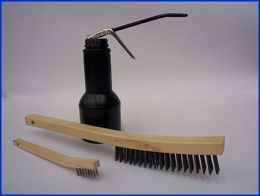
2 Tools What s in your tool box? What is important when it comes to wheels? 2
3 3
4 Trouble Shooting Wheel End Looseness Technology & Maintenance Council s RP 238 4

5 TMC RP 238 5

6 TMC RP 238, continued 6

7 TMC RP 238, continued 7
8 8

9 Recommended Installation Procedure Check all parts for damage, including rims/wheels Ensure that studs, nuts, mounting surfaces of the hub, drum, and wheels are flat, clean, and free of grease. 9


10 Recommended Installation Procedure 1. Use correct components 2. Before reusing flange-nuts that have already been in service, apply 2-3 drops of 30 weight oil to the swivel joint. This will allow the parts to rotate freely and provide the proper clamping force when tightened. Excessive lubricant is not desirable. Anti-Seize compounds are not recommended. 3. Before reinstalling nuts apply 2-3 drops of 30 weight oil to the first 2-3 threads of the studs. Be sure that the studs have been cleaned of excessive paint, rust/corrosion and debris with a wire brush. 10

11 Recommended Installation Procedure Before installing the wheel, lubricate the hub-pilot pads with a drop of 30 weight oil to prevent galling. Do not lubricate any other wheel or hub surface. This has potential to cause clamping force issues. 11

12 Recommended Installation Procedure An alternate lubrication method is a thin skim of a rust inhibitive lubricant such as Frey Lube No Rim Rust. Do not lubricate any other wheel or hub surface. 12


13 Hub Pilot Lubrication The industry is moving toward the recommendation of rust-inhibitive lubricants for hub pilot pads or hub bore on aluminum wheels. Anti-Seize compounds are not recommended. Two recommended lubricants are shown. 13

14 Recommended Installation Procedure During the wheel installation process it is recommended to: Position a hub pilot pad a the 12:00 position Lubricate the hub pilot pads Snug wheel nuts in the proper torque sequence shown Then proceed to torque the wheels to 450 to 500 ft-lbs using the proper torque sequence shown After the first 50 to 100 miles wheel nuts should be re-torqued to the proper torque level. Refer to Accuride s Safety and Service Manual pages 46 through 52 for complete servicing procedures. 14

15 Recommended Installation Procedure Torque wheel fasteners to foot pounds. 15

16 Recommended Installation Procedure 16
17 Retorquing Guidelines for Disc Wheels Technology & Maintenance Council s RP

18 TMC RP

19 TMC RP

20 TMC RP

21 Recommended Installation Procedure Refer to the Accuride Safety & Service manual or industry manuals for proper procedures for your wheel system. 21
22 The Effect of Torque and Clamping Force On Keeping Wheels Tight 22

23 Wheel Installation Fastener Installation & Torquing Clamping Forces Tension Tension Torque to 500 Ft lb 23
24 Torque and Clamping Force 22mm Studs & 2-Piece Flanged Nuts 24

25 The Negative Effect of Fastener Age 25

26 The Effect of Fastener Age 22mm Studs & 2-Piece Flanged Nuts Data is based on a fleet study with four year old, used 22mm Grade 8 Studs and 2-Piece Flange Nuts 26
27 Hub & Spoke Wheel Fastener Maintenance TMC RP
28 TMC RP 656 (T) 28
29 TMC RP 656 (T) 29
30 The Effect of Scale, Corrosion, Excess Paint On Keeping Wheels Tight 30


31 The Negative Effect of Scale and Corrosion on Mounting Surfaces 31


32 The Negative Effect of Too Much Paint Paint thickness gauge shows mils or inches, which exceeds the maximum allowable of 3.5 mils or.0035 inches. 1. Examples of too much paint. The maximum allowable paint thickness is.0035 or about the thickness of an average magazine page. Paint on these wheels measured from.016 to One rule of thumb is that if you cannot read the stamping on the wheel there is too much paint. 3. These wheels should be repaired before being returned to service and installed on a vehicle. 32

33 The Negative Effect of Too Much Paint Thick Paint or Debris Thick paint/debris works out while vehicle is being driven Thick paint/debris works out while vehicle is being driven If wheels are installed with excessive paint thickness, debris, or excessive corrosion as shown above in dark orange The paint, debris, and corrosion will gradually work its way out during operation and The wheel(s) will become loose, which could result in cracked or broken wheels, damaged brake drums, broken studs, and wheel separation from the vehicle. 33


34 The Negative Effect of Too Much Paint Emergency Wheel Repair ALWAYS USE PROPER SAFETY/PROTECTION EQUIPMENT 1.Thoroughly remove all paint or rust/corrosion from the mounting surfaces. Use power wire brushes or die grinders with ScotchBrite pads. Course sand paper on power tools or grinding discs are not recommended because they may create deep scratches in the metal which could cause cracking. 34

35 The Negative Effect of Too Much Paint ALWAYS USE PROPER SAFETY/PROTECTION EQUIPMENT Emergency Wheel Repair 2. Paint the mounting surfaces with a fast drying white enamel paint. Do not apply too much paint. Paint should not exceed.035 mils. That is approximately the thickness of an average magazine page. Apply just enough paint to hide the metal surface under the paint.* 3. Allow adequate time for the paint to fully dry (or cure). 4. As an alternative, a professional wheel refinishing company Is recommended. *Know and follow all local paint application regulations. 35

36 Review of Actual Wheel Off Incident 36
37 Avoiding Loose Wheels THANK YOU Brandon G. Uzarek Field Engineering
38 Industry-Leading Commercial Vehicle Products
Hub Installation and Bearing Adjustment. Hub Installation and Bearing Adjustment. Hub Preparation Prior to Installation
 Hub Installation and Bearing Adjustment Hub Installation and Bearing Adjustment Scope: This service procedure is intended to provide general instructions for reinstallation of a hub onto an axle after
System: Wheels Bulletin #: Date: March 1, 2001 Replaces: June 26, Wheel Separations
 System: Wheels Bulletin #: 18-00 Date: March 1, 2001 Replaces: June 26, 1992 Wheel Separations Wheel separations (wheels coming off as the unit is running down the road) are covered in awareness bulletins
Recommended Practice
 Recommended Practice Proposed RP 261 (T) VMRS 004-013-001 CONSIDERATIONS FOR AERODYNAMIC WHEEL COVERS PREFACE The following Recommended Practice is subject to the Disclaimer at the front of TMC s Recommended
HUB & WHEEL INSTALLATION
 HUB & WHEEL INSTALLATION 1.0 SCOPE This specification covers the torque requirements for the attachment of all component parts of Spoke Wheels, Rims, Tyres and Hub assemblies. 1.1 Spoke Wheels CAUTION:
Installation Instructions
 Preparing your vehicle to install your brake system upgrade 1. Rack the vehicle. 2. If you don t have a rack, then you must take extra safety precautions. 3. Choose a firmly packed and level ground to
Read all instructions carefully before attempting installation. 1633S-1JS Shown. Rev DSL
 Corporate Office: PerTronix Inc. 440 E. Arrow Highway, San Dimas, California 91773 * Phone 909.599.5955 FAX 909.599.6424 Installation Instructions and Warranty Information 1630S 86-87 Ranger/Bronco II
Installation Instructions and Warranty Information
 Corporate Office: PerTronix Inc. 440 E. Arrow Highway, San Dimas, California 91773 * Phone 909.599.5955 FAX 909.599.6424 Installation Instructions and Warranty Information Part #1627S 1987-95 F-150/Bronco
Read all instructions carefully before attempting installation. REV DSL
 Corporate Office: PerTronix Inc. 440 E. Arrow Highway, San Dimas, California 91773 * Phone 909.599.5955 FAX 909.599.6424 Installation Instructions And Warranty Information Part # 6830S ~ Small Block Chevrolet
Service Procedure. 1. Raise the vehicle on a suitable hoist and support as necessary. 2. Remove both front tires and wheels.
 Service Procedure The following procedure provides instructions for repairing a corrosion condition where the front wheel speed sensor mounts on the front wheel bearing assembly. 1. Raise the vehicle on
Installation Instructions and Warranty Information
 Corporate Office: PerTronix Inc. 440 E. Arrow Highway, San Dimas, California 91773 * Phone 909.599.5955 FAX 909.599.6424 Installation Instructions and Warranty Information Chevrolet & GMC Silverado/Sierra,
Read all instructions carefully before attempting installation.
 Corporate Office: PerTronix Inc. 440 E. Arrow Highway, San Dimas, California 91773 * Phone 909.599.5955 FAX 909.599.6424 Installation Instructions And Warranty Information Ford Ranger/Explorer/Sport Trac
SERVICE MANUAL L130B / L4130 Series Logstacker Drive Axle With Bolt-On Stub End Retainer
 SERVICE MANUAL L130B / L4130 Series Logstacker Drive Axle With Bolt-On Stub End Retainer Page 1 Allied Form #80-930 Rev 07/2009 SERVICE MANUAL LOG STACKER DA202 DRIVE AXLE TABLE OF CONTENTS PROCEDURE FOR
Clutch, servicing. Special tools, testers and auxiliary items required. Flywheel retainer Thrust pad 3062
 Page 1 of 10 30-36 Clutch, servicing Special tools, testers and auxiliary items required Flywheel retainer 10-201 Thrust pad 3062 Page 2 of 10 30-37 Centering mandrel 3176 Grease G 000 100 Notes: Observe
Installation Instructions and Warranty Information
 Corporate Office: PerTronix Inc. 440 E. Arrow Highway, San Dimas, California 91773 * Phone 909.599.5955 FAX 909.599.6424 Installation Instructions and Warranty Information Part # 1685S 2011-2014 Mustang
Installation Instructions And Warranty Information
 Corporate Office: PerTronix Inc. 440 E. Arrow Highway, San Dimas, California 91773 * Phone 909.599.5955 FAX 909.599.6424 Installation Instructions And Warranty Information 1964 1/2 to 73 Ford Mustang/Mercury
Part Numbers: Complete Kits: C5 Base/Z06 Complete Header Package with Cats C5 Base/Z06 Complete Header Package without Cats
 Product: Corvette Tri-Y Headers & Mid-Pipe Part Numbers: Complete Kits: 1150042 C5 Base/Z06 Complete Header Package with Cats 1150043 C5 Base/Z06 Complete Header Package without Cats Applications: Chevrolet
INSTALLATION INSTRUCTIONS
 INSTALLATION INSTRUCTIONS 2102 LOWERING SPINDLE ASSEMBLY 1998-UP CHEVROLET / GMC BLAZER / X-TREME / JIMMY / ENVOY 2 Wheel Drive Congratulations! You were selective enough to choose a BELLTECH PRODUCT.
CSS-C CHEVROLET SUBURBAN & TAHOE WD AND 2WD CHEVROLET AVALANCHE WD AND 2WD 6-8 SUSPENSION LIFT KIT
 14385 Veterans Way Moreno Valley, CA 92553 Phone: (951) 571-0212 Fax: (951) 571-0215 WWW.CSTSUSPENSION.COM CSS-C3-3 2000-2006 CHEVROLET SUBURBAN & TAHOE 1500 4WD AND 2WD 2002-2006 CHEVROLET AVALANCHE 1500
Refer to separate Installation Instructions for installation details.
 OWNER S GUIDE 8A000729 DuraLift 13.5 13,500 CAPACITY Link Mfg. Ltd. 223 15th St. N.E. Sioux Center, IA USA 51250-2120 www.linkmfg.com QUESTIONS? CALL CUSTOMER SERVICE 1-800-222-6283 DEALER / INSTALLER:
M-2300-T 6-Piston Mustang Brake Kit INSTALLATION INSTRUCTIONS
 Please visit www.fordracingparts.com for the most current instruction information!!! PLEASE READ ALL OF THE FOLLOWING INSTRUCTIONS CAREFULLY PRIOR TO INSTALLATION. AT ANY TIME YOU DO NOT UNDERSTAND THE
Kysor On/Off Rear Air Fan Drive
 . Proper precautions must be taken to prevent personal injury from contact with moving parts, unintended engine start, or other hazards present when working with powered equipment. Refer to the vehicle
INSTRUCTIONS FOR INSTALLATION OF THE CH-2 and CH-3 DRIVE UNIT TO AN ENGINE WARNING
 INSTRUCTIONS FOR INSTALLATION OF THE CH-2 and CH-3 DRIVE UNIT TO AN ENGINE WARNING! Never reach hands or other body parts in or near moving parts!! Maintain a safe distance from any fixed or moving propeller!!
For JBA Headers /302 Mustang
 Corporate Office: PerTronix Inc. 440 E. Arrow Highway, San Dimas, California 91773 * Phone 909.599.5955 FAX 909.599.6424 Installation Instructions and Warranty Information For JBA Headers 1965-1973 289/302
GUNITE Disc Wheel Hubs
 GUNITE Disc Wheel Hubs Maintenance & Installation Manual C O R P O R A T I O N Gunite offers a complete line of traditional ferrous disc wheel hubs for all of today s heavy-duty axle applications. In addition,
Kysor Rear Air Fan Drives
 On/Off Technology for Heavy-Duty Truck Applications Installation & Service Guide Kysor Rear Air Fan Drives thermal.borgwarner.com For Additional BorgWarner Thermal Systems Information: 800-927-7811 USA
Installation Instructions and Warranty Information
 Corporate Office: PerTronix Inc. 440 E. Arrow Highway, San Dimas, California 91773 * Phone 909.599.5955 FAX 909.599.6424 Installation Instructions and Warranty Information Part # 6612S For JBA Headers
Installation Instructions And Warranty Information
 Corporate Office: PerTronix Inc. 440 E. Arrow Highway, San Dimas, California 91773 * Phone 909.599.5955 FAX 909.599.6424 Installation Instructions And Warranty Information 1999-2006 Chevrolet/GMC 2WD 1500,
FR11A Fender, Welded-On
 Uniform Procedures For Collision Repair FR11A Fender, Welded-On 1. Description This procedure describes the repair and complete replacement of a welded-on aluminum fender. Inspection and evaluation requirements
Installation Instructions and Warranty Information Ford Small Block Street Rod Headers Part # 1615S
 Corporate Office: PerTronix Inc. 440 E. Arrow Highway, San Dimas, California 91773 * Phone 909.599.5955 FAX 909.599.6424 Installation Instructions and Warranty Information Ford Small Block Street Rod Headers
ASSEMBLY INSTRUCTIONS FOR DYNAPRO BIG BRAKE FRONT HAT KIT, WITH DIAMETER VENTED ROTOR - RACE
 www.wilwood.com ASSEMBLY INSTRUCTIONS FOR DYNAPRO BIG BRAKE FRONT HAT KIT, WITH 11.75 DIAMETER VENTED ROTOR - RACE 00 - PRESENT BMW MINI COOPER AND MINI COOPER S PART NUMBER GROUP 10-870 DISC BRAKES SHOULD
M-4851-M8A SUPER 8.8 IRS MUSTANG AUTOMATIC PINION FLANGE KIT
 Please visit fordperformanceracingparts.com for the most current instruction information!!! PLEASE READ ALL OF THE FOLLOWING INSTRUCTIONS CAREFULLY PRIOR TO INSTALLATION. AT ANY TIME YOU DO NOT UNDERSTAND
Installation Instructions and Warranty Information Part# 6400S / 36400S Nissan Titan/Armada 5.6L Infinity QX56 5.
 Corporate Office: PerTronix Inc. 440 E. Arrow Highway, San Dimas, California 91773 * Phone 909.599.5955 FAX 909.599.6424 Installation Instructions and Warranty Information Part# 6400S / 36400S 2004-14
Toyota Truck Park Brake Bellcrank Repair
 Toyota Truck Park Brake Bellcrank Repair Toyota trucks including Tacoma, T100 and Tundra with rear drum brakes use a bellcrank apparatus through the brake backing plate as part of the parking brake system.
INSTALLATION INSTRUCTION 88148
 INSTALLATION INSTRUCTION 88148 Rev C For Rancho Suspension Systems RS6548, RS6549 & RS6550: GM 2500HD, 2500, and 1500HD Trucks READ ALL INSTRUCTIONS THOROUGHLY FROM START TO FINISH BEFORE BEGINNING INSTALLATION
SuperTrac. Axle. Service & Maintenance. Manual
 SuperTrac Axle Service & Maintenance Manual Table of Contents Page Exploded Views Section 1: General Information General Warnings Description of Axle Models Identifications Section 2: Installation Axle
JEEP JK4 STEP SLIDER INSTALLATION BD-SS-100-JK4
 JEEP JK4 STEP SLIDER INSTALLATION BD-SS-100-JK4 PARTS LIST QTY DESCRIPTION 1 Drivers Side Slider Assembly 1 Passenger Side Slider Assembly 1 Wiring Harness and Fuse 1 Double Sided Sticky Squares and Alcohol
JEEP JK4 STEP SLIDER INSTALLATION BD-SS-100-JK4
 JEEP JK4 STEP SLIDER INSTALLATION BD-SS-100-JK4 PARTS LIST QTY DESCRIPTION 1 Drivers Side Slider Assembly 1 Passenger Side Slider Assembly 1 Wiring Harness and Fuse 1 Double Sided Sticky Squares and Alcohol
STaSIS Engineering MkV Mono4 Front Brakes
 STaSIS Engineering MkV Mono4 Front Brakes 370mm Brake Kit KB04.1002 Parts List: Qty Description Part Number 1 Rotor Alcon 370x28 RH BR01.1020.00 1 Rotor Alcon 370x28 LH BR01.1021.00 2 MkV 370 Brake Hat
INSTALLATION INSTRUCTION 88051
 INSTALLATION INSTRUCTION 88051 For Rancho Suspension System RS6551: Chevrolet 2500 Suburban & 2500 Avalanche READ ALL INSTRUCTIONS THOROUGHLY FROM START TO FINISH BEFORE BEGINNING INSTALLATION Rev C IMPORTANT
2005 Dodge Grand Caravan
 REMOVAL REMOVAL - REAR DISC BRAKE SHOES 1. Raise vehicle. (Refer to LUBRICATION & MAINTENANCE/HOISTING - STANDARD PROCEDURE). 2. Remove rear wheel and tire assemblies from vehicle. 3. Remove the caliper
NV3550 TO FORD BRONCO
 NV3550 TO 1966-77 FORD BRONCO KIT CONSISTS OF: No. 1. 2. 3. 4. 5. Qty 1 1 Kit 1 Kit 1 Kit 1 Kit Part No. 26-3550 50-9920 712544 716000 716099 Description NV3550 TRANSMISSION TRANSFER CASE ADAPTER & TC
Read all instructions carefully before attempting installation. REV DSL
 Corporate Office: PerTronix Inc. 440 E. Arrow Highway, San Dimas, California 91773 * Phone 909.599.5955 FAX 909.599.6424 Installation Instructions and Warranty Information Part# 6035S/30635S 2005-2008
2/22/2018 Camshaft Timing Drive Components Cleaning and Inspection 2007 Saturn Aura MotoLogic
 2007 Aura Applies to: 3.6L Report a problem with this article Cleaning Procedure Important: Some models use a second design inverted tooth timing drive system on the secondary drive components. Refer to
Product: Cadillac ATS 2.0T Downpipe. Part Numbers: Downpipe 2.0T - with catalytic converter Downpipe 2.
 Product: Cadillac ATS 2.0T Downpipe Part Numbers: 1180111 Downpipe 2.0T - with catalytic converter 1180112 Downpipe 2.0T - Race Only Applications: Cadillac ATS 2.0T, 2013 - Current Description: These downpipe
INSTALLATION INSTRUCTIONS 88518
 INSTALLATION INSTRUCTIONS 88518 For Rancho Suspension Systems RS6518: 2009 FORD F-150 4WD READ ALL INSTRUCTIONS THOROUGHLY FROM START TO FINISH BEFORE BEGINNING INSTALLATION Rev A IMPORTANT NOTES! WARNING:
STEERING AND SUSPENSION SYSTEMS
 STEERING AND SUSPENSION SYSTEMS UNIT 12: WHEEL AND TIRE DESIGN LESSON 1: WHEEL DESIGN I. Basic wheel construction A. Wheels are made from stamped steel or cast or forged aluminum or alloys. B. A wheel
CSS-C SUSPENSION LIFT KIT
 115 W. La Cadena Dr. Ste 100 Riverside, CA 92501 (951) 328-9902 phone (951) 328-9908 fax 2000-2006 CHEVROLET SILVERADO 1500 4WD CSS-C3-2 6-8 SUSPENSION LIFT KIT WARNING: CALIFORNIA SUPERTRUCKS RECOMMENDS
Installation Manual v1.3: 2-Piece Exhaust Manifold Dodge 5.9L. Please read all instructions before installation.
 Installation Manual v1.3: 2-Piece Exhaust Manifold 2003-2007 Dodge 5.9L Please read all instructions before installation. Figure 1 - Dodge 2-Piece Exhaust Manifold Kit 1. Disconnect BOTH negative (-) battery
Installation Instructions and Warranty Information 1688S Ford F V8
 Corporate Office: PerTronix Inc. 440 E. Arrow Highway, San Dimas, California 91773 * Phone 909.599.5955 FAX 909.599.6424 Installation Instructions and Warranty Information 1688S 2011-14 Ford F-150 5.0
PART NO. DESCRIPTION NEW ATTACHING HARDWARE (Qty.- if more than one) link arm, front / lower...(2) bushing half
 link arm, front / lower...(2) bushing half") INTRODUCTION Installation requires a professional mechanic. Prior to beginning, inspect the vehicle s steering, driveline, and brake systems, paying close attention to the suspension link arms and bushings,
INTRODUCTION Installation requires a professional mechanic. Prior to beginning, inspect the vehicle s steering, driveline, and brake systems, paying close attention to the suspension link arms and bushings,
Superlift Level-It System for FORD F-150 4WD INSTALLATION INSTRUCTIONS
 FORM #40021.03-072617 PRINTED IN U.S.A. PAGE 1 OF 6 Superlift Level-It System for 2009-2017 FORD F-150 4WD INSTALLATION INSTRUCTIONS INTRODUCTION Installation requires a professional mechanic. Prior to
TYPE E Main Valve Sizes 3 /8 through 12
 Technical Data SD 3001E PRINTED IN U.S.A. SD 3001E/9709 SPENCE ENGINEERING COMPANY, INC. 150 COLDENHAM ROAD, WALDEN, NY 12586-2035 A B TYPE E MAIN VALVE FACE TO FACE DIMENSIONS C D E DIMENSIONS (inches)
M-2300-WR Focus ST Performance RS Rear Brake Kit
 Please visit www. performanceparts.ford.com for the most current instruction and warranty information. PLEASE READ ALL OF THE FOLLOWING INSTRUCTIONS CAREFULLY PRIOR TO INSTALLATION. AT ANY TIME YOU DO
INSTALLATION INSTRUCTIONS
 INSTALLATION INSTRUCTIONS 2007-14 GM C/K1500 4 SYSTEM w/uniball UPPER CONTROL ARMS FOR USE WITH FACTORY STEEL SUSPENSION ONLY FTS21135 - SYSTEM w/performance SHOCKS FTS21136 - SYSTEM w/dirt LOGIC SHOCKS
For JBA Headers 641/2 to /302/5.0L EFI Ford Mustang & Mercury Cougar
 Corporate Office: PerTronix Inc. 440 E. Arrow Highway, San Dimas, California 91773 * Phone 909.599.5955 FAX 909.599.6424 Installation Instructions and Warranty Information For JBA Headers 641/2 to 73 289/302/5.0L
2005 Cadillac CTS BRAKES Disc Brakes - CTS
 Removal Procedure 1. Inspect the fluid level in the brake master cylinder reservoir. 2. If the brake fluid level is midway between the maximum-full point and the minimum allowable level, no brake fluid
Mustang V6 Shaker 99-04* Components Check List:
 Mustang V6 Shaker 99-04* Components Check List: *03 Model requires new hood CDC Inspected Installer Check Quantity Descriptions 1- Hood Appliqué 1- Aluminum Shaker Scoop 1- Lower Air Box w/drain tube fittings
2005 Cadillac CTS BRAKES Disc Brakes - CTS
 Removal Procedure 1. Inspect the fluid level in the brake master cylinder reservoir. 2. If the brake fluid level is midway between the maximum-full point and the minimum allowable level, no brake fluid
Written By: Hybrid Racing
 Hybrid Racing K-Series 70MM Throttle Body Below you will find tips on how to install your new Hybrid Racing K Series 70MM Throttle Body into a Honda K series equipped vehicle. *This product may not be
Wheels. Wheels and Tires ! CAUTION. Wheel Selection
 Wheel Selection Wheels Wheels are very important and critical components of your running gear system. When specifying or replacing your trailer wheels it is important that the wheels, tires, and axle are
REMOVAL & INSTALLATION
 REMOVAL & INSTALLATION REAR DISC BRAKE PADS Removal Raise and support vehicle. Remove wheels. Thoroughly clean outside of caliper to prevent dust and dirt from entering inside. Support caliper with a piece
Wheels. Wheels and Tires ! CAUTION. Wheel Selection
 Wheels Wheel Selection Wheels are a very important and critical component of your running gear system. When specifying or replacing your trailer wheels it is important that the wheels, tires, and axle
GM LS Series Serpentine Drive System with & without Power Steering
 an ISO 9001:2015 Registered Company GM LS Series Serpentine Drive System with & without Power Steering 18865 Goll St. San Antonio, TX 78266 Phone: 800-862-6658 Sales: sales@vintageair.com Tech Support:
DIFFERENTIALS & AXLE SHAFTS
 DIFFERENTIALS & AXLE SHAFTS 2001 Chevrolet Camaro 2000-01 DRIVE AXLES General Motors Differentials & Axle Shafts Chevrolet; Camaro Pontiac; Firebird DESCRIPTION & OPERATION Drive axle is a semi-floating,
Installation Instructions
 86-95 Suzuki Samurai Rear Wheel Bearing Kit (SKU# SAX-RWB) Instructions also include:! Rear Hub Bolt Kit!!!! (SKU# SAX-AS)!! SJ410 Backing Plate!!!! (SKU# SAX-410)! SJ413 Rear Drum Brake Hardware Kit!
Wheel end service for greased wheel ends
 wheel ends Page 1 Tech tip Scope This document recommends procedures for servicing greased wheel ends. Included are SKF recommendations for manually adjusted, hard greased (NLGI 1, 2, and 3) and semi-fluid
ASSEMBLY INSTRUCTIONS FOR PRO-MATRIX OE UPGRADE PAD AND ROTOR KIT REAR, WITH DIAMETER VENTED ROTOR CHEVROLET C-4 CORVETTE
 ASSEMBLY INSTRUCTIONS FOR PRO-MATRIX OE UPGRADE PAD AND ROTOR KIT REAR, WITH 1.00 DIAMETER VENTED ROTOR 1988-1996 CHEVROLET C-4 CORVETTE PART NUMBER GROUP 140-8314 DISC BRAKES SHOULD ONLY BE INSTALLED
For Toyota Tundra 4.7L V-8 Two and Four Wheel Drive
 Corporate Office: PerTronix Inc. 440 E. Arrow Highway, San Dimas, California 91773 * Phone 909.599.5955 FAX 909.599.6424 Installation Instructions and Warranty Information For 2000-2004 Toyota Tundra 4.7L
servicing the swivel
 servicing the swivel The swivel seals and bearings require periodic replacement. This document describes how to determine which service procedure to use to service the swivel assembly, part number 101110.
Betico SB1 Compressor. Unloader Kit Installation Manual
 Betico SB1 Compressor Unloader Kit Installation Manual Contents 1. Sample of BOM for Unloader Kit Page 3 2. Regulation kit plumbing diagram Page 4 3. Disassemble standard inlet valves from machine Page
TJ YJ LJ STEP SLIDER INSTALLATION
 TJ YJ LJ STEP SLIDER INSTALLATION BD-SS-100-TJ, BD-SS-100-YJ, BD-SS-100-LJ PARTS LIST QTY DESCRIPTION 1 Drivers Side Slider Assembly 1 Passenger Side Slider Assembly 1 Wiring Harness 1 Double Sided Sticky
2216 (STOCK) / 2224 (3 LOWER) 2WD SPORT SWAY BAR SET 97-UP DODGE DAKOTA INSTALLATION OF HOTCHKIS PERFORMANCE FRONT SWAY BAR
 / 2224 (3 LOWER) 2WD SPORT SWAY BAR SET 97-UP DODGE DAKOTA INSTALLATION OF HOTCHKIS PERFORMANCE FRONT SWAY BAR") 2216 (STOCK) / 2224 (3 LOWER) 2WD SPORT SWAY BAR SET 97-UP DODGE DAKOTA Thank you for your purchase from our line of Dodge Dakota & Durango suspension parts. Please call us at (877) 4NO-ROLL if you have
2216 (STOCK) / 2224 (3 LOWER) 2WD SPORT SWAY BAR SET 97-UP DODGE DAKOTA Thank you for your purchase from our line of Dodge Dakota & Durango suspension parts. Please call us at (877) 4NO-ROLL if you have
CLEANING, INSPECTION AND REPAIR. Valve Spring Compressor (Part No. HD-34736B) Figure Compressing Valve Springs
 Figure Compressing Valve Springs") b0134x3x 5694 8 7 12 10 1 6 13 11 Valve Spring Compressor (Part No. HD-34736B) 9 Figure 3-11. Compressing Valve Springs 5 14 4 3 2 15 2767a 1. Right crankcase half 2. Pin (2) 3. O-ring (2) 4. Plate 5.
b0134x3x 5694 8 7 12 10 1 6 13 11 Valve Spring Compressor (Part No. HD-34736B) 9 Figure 3-11. Compressing Valve Springs 5 14 4 3 2 15 2767a 1. Right crankcase half 2. Pin (2) 3. O-ring (2) 4. Plate 5.
Drive Axles SHAIS171. The Dana LMS Hub is available on the following Steer and Drive Axle Models:
 Information Sheet Spicer Drive Axles SHAIS171 Topic: Dana LMS Hub Assembly Procedure Steer and Drive Axles Note: Bulletin ABIB-0302 replaces the original bulletin ABIB-9606. The Dana LMS hub design eliminates
Part # 1528S. Read all instructions carefully before attempting installation.
 Corporate Office: PerTronix Inc. 440 E. Arrow Highway, San Dimas, California 91773 * Phone 909.599.5955 FAX 909.599.6424 Installation Instructions and Warranty Information 2007-2008 Jeep Wrangler Part
Installation Instructions
 Installation Instructions Jeep TJ Long Arm Suspension System 1997-2002 JEEP TJ 4WD 6 1997-2002 JEEP TJ 4WD FTS24002 & BK / FTS24003 & BK / FTS44002 & BK PARTS LIST FTS24002BK Jeep TJ 6' Box Kit 1 FTS24003BK
DYNATRAC V6.0. WARNING: Only perform this installation if you are experienced, fully equipped mechanic.
 DYNATRAC V6.0 1999-2004 Ford Super Duty 250/550-4x4, Front Axle, Free Spin Conversion Kit Some of the less common tools, which will be required: 6 point Spanner socket (OTC #7090-A or equivalent) OR 4
Installation Instructions and Warranty Information
 Corporate Office: PerTronix Inc. 440 E. Arrow Highway, San Dimas, California 91773 * Phone 909.599.5955 FAX 909.599.6424 Installation Instructions and Warranty Information JBA Headers for JEEP Wrangler
Northstar RIM Tach Steps to Installation. K Wheel (Clamp Style)
") Northstar RIM Tach 8500 10 Steps to Installation K Wheel (Clamp Style) Mill Duty High Performance & Rugged Most Reliable magneto-resistive digital tach on the market today Ductile Iron Housing & Stainless
Northstar RIM Tach 8500 10 Steps to Installation K Wheel (Clamp Style) Mill Duty High Performance & Rugged Most Reliable magneto-resistive digital tach on the market today Ductile Iron Housing & Stainless
INSTALLATION INSTRUCTIONS
 Product: Steering Stabilizer Relocation Kit Part Number: JKSOGS900 (JKSOGS162/JKSJSPEC1000/JKSOGS924) INSTALLATION INSTRUCTIONS Applications: Wrangler JK, 2007+ Welcome CONGRATULATIONS on purchasing a
Installation Instructions and Warranty Information
 Corporate Office: PerTronix Inc. 440 E. Arrow Highway, San Dimas, California 91773 * Phone 909.599.5955 FAX 909.599.6424! Installation Instructions and Warranty Information 1967-1970 Ford Mustang 390,
1984 Dodge W250 PICKUP
 1984 Dodge W250 PICKUP Submodel: Engine Type: V8 Liters: 5.2 Fuel Delivery: CARB Fuel: GAS Dana 44 MODELS THROUGH 1984 2. Raise and safely support the vehicle, then remove the wheel hub and bearings as
Explanatory Information (NOT PART OF ANSI STANDARD)
") 6 Mounting 6.1 Inspection Prior to mounting, all wheels shall be inspected for damage and cracks. Wheels which show any evidence of cracks, abusive handling or abusive storage shall not be mounted. 6.1.1
6 Mounting 6.1 Inspection Prior to mounting, all wheels shall be inspected for damage and cracks. Wheels which show any evidence of cracks, abusive handling or abusive storage shall not be mounted. 6.1.1
REBUILT NV3550 TO FORD BRONCO
 KIT CONSISTS OF: PAGE 1 OF 6 Page Rev. Date: 08-15-16 No. Qty Part No. Description 1. 1 26-3550R REMANUFACTURED NV3550 TRANSMISSION 2. 1 Kit 50-9920 TRANSFER CASE ADAPTER & TC SHIFTER BRKT. 3. 1 Kit 712544
CYLINDER HEAD. Cylinder Head Assembly. Sized for Print VALVES
 CYLINDER HEAD Cylinder Head Assembly VALVES DISASSEMBLY 1. Using a tool remove the cylinder head bolts in the order shown in the illustration. 2. Using the special tool (09222-28000, 09222-28100), remove
80-96 Ford F150 / Bronco 4WD Class II 4"- 6" Suspension Lift Installation Instructions
 www.skyjacker.com Required Tool List: 80-96 Ford F150 / Bronco 4WD Class II 4"- 6" Suspension Lift Installation Instructions Safety Glasses Metric / Standard Wrenches & Sockets Floor Jack Jack Stands Measuring
Installation Guide for the TJ LCG PRO Suspension System (Low Center of Gravity) Available 4 or 5
 Available 4 or 5") INSTALLATION GUIDE Installation Guide for the TJ LCG PRO Suspension System (Low Center of Gravity) Available 4 or 5 Take every precaution to make this installation a safe procedure. Make safety the number
INSTALLATION GUIDE Installation Guide for the TJ LCG PRO Suspension System (Low Center of Gravity) Available 4 or 5 Take every precaution to make this installation a safe procedure. Make safety the number
INSTALLATION INSTRUCTION 88088
 INSTALLATION INSTRUCTION 88088 For Rancho Suspension Systems RS6588 & RS6589: FORD F-150 READ ALL INSTRUCTIONS THOROUGHLY FROM START TO FINISH BEFORE BEGINNING INSTALLATION Rev B IMPORTANT NOTES! WARNING:
Installation Instructions
 Instructions Created by an: 1986-1995 Toyota Pickup 4Runner Hilux Front Ball Joint Spacer Kit - 2.5" 64mm Lift by Low Range Off-Road (SKU# TSP-BJS-1.5 & TSP-BJS-1.5-W/Shocks) Installation Instructions
CP-1, CP-2, CP-2L & CPD-2 Series Overhaul
 Replacement of Mechanical Seals for CM, CMU, CS and CSU Series Pumps Installation Instructions Form No. F-1031 Section 5013 Issue Date 03/01/85 Rev. Date 02/08/11 CP-1, CP-2, CP-2L & CPD-2 Series Overhaul
Wheel Spacer. center bore thin spacer. brake rotor and hub. raised hub. thicker spacer. Page - 1
 center bore thin Things you need to do: 1) Select the correct. Pick s that match your bolt pattern. Then use our online video to help you select the correct thickness. The video demonstrates how to use
PPM 8069 JK FRONT TRACKBAR BRACE / SECTOR SHAFT BRACE INSTALLATION INSTRUCTIONS
 Poly Performance MFG, 870 Industrial Way, San Luis Obispo, CA 93401, (805) 242-0397 PPM 8069 JK FRONT TRACKBAR BRACE / SECTOR SHAFT BRACE INSTALLATION INSTRUCTIONS **DISCLAIMER** The Synergy Suspension
FR01A Fender, Bolted-On
 Uniform Procedures For Collision Repair UPCR FR01A Fender, Bolted-On 1. Description This procedure describes the repair and complete replacement of a bolted-on aluminum fender. Inspection and evaluation
Wheel Spacer. center bore thin spacer. brake rotor and hub. raised hub. thicker spacer. Page - 1
 Wheel Spacer center bore thin spacer Things you need to do: 1) Select the correct spacer. Pick spacers that match your bolt pattern. Then use our online video to help you select the correct spacer thickness.
Toyota Tacoma Winch Mount Bumper Installation Instructions Tools Required: Transmission cooler relocation brackets Torque Wrench
 2016-2017 Toyota Tacoma Winch Mount Bumper Installation Instructions Tools Required: Items Included: Small flat head screw driver Winch Mount Ratchet, 10mm, 12mm, 14mm, 17mm & Skid Plate 19mm sockets Transmission
SERVICE MANUAL. PreSet Hub Assemblies. Conventional. Hub & Rotor Assemblies. PreSet Plus. For Steer, Drive and Trailer Hub Assemblies.
 Conventional Hub Assemblies PreSet Hub Assemblies PreSet Plus Hub Assemblies Hub & Rotor Assemblies SERVICE MANUAL For Steer, Drive and Trailer Hub Assemblies About This Manual Before You Begin Read this
INSTALLATION INSTRUCTIONS
 INSTALLATION INSTRUCTIONS 2007-2015 GM C/K1500 TRUCK/SUV 4 BUDGET SYSTEM FOR USE WITH FACTORY STEEL SUSPENSION ONLY FTS21121/FTS21124 - w/ REAR PERFORMANCE SHOCKS FTS21186/FTS21187 - w/ STEALTH SHOCKS
Read all instructions carefully before attempting installation. Rev DSL
 Corporate Office: PerTronix Inc. 440 E. Arrow Highway, San Dimas, California 91773 * Phone 909.599.5955 FAX 909.599.6424 Installation Instructions and Warranty Information 2011S - 05-06 Tundra 05-07 Sequoia
TIRES AND WHEELS 22-1 TIRES AND WHEELS CONTENTS
 ZJ TIRES AND WHEELS 22-1 TIRES AND WHEELS CONTENTS TIRES... 1 WHEELS... 7 TIRES INDEX DESCRIPTION AND OPERATION RADIAL-PLY TIRES... 2 REPLACEMENT TIRES... 3 SPARE TIRE TEMPORARY... 2 TIRE INFLATION PRESSURES...
This file is available for free download at
 This file is available for free download at http://www.iluvmyrx7.com This file is fully text-searchable select Edit and Find and type in what you re looking for. This file is intended more for online viewing