Goulds Centrifugal Pump Model 3196 Mfg: Goulds Model: Goulds Centrifugal Pump.
|
|
|
- Georgina Ball
- 6 years ago
- Views:
Transcription


1 Goulds Centrifugal Pump Model 3196 Mfg: Goulds Model: 3196 Stock No. OIP016. Serial No. 788B861 Goulds Centrifugal Pump. Model S/N 788B861. Size 1 in. x1-1/2 in. x 8 in. Water flush double mechanical seals. Motor 1.5 hp, 1,730 rpm, 230/460 V, 60 Hz, 5.6/2,8 amps, 3 phase, Capacity 14 gpm. Overall Dimensions 35 in. L x 12 in. W x 15 in. H.


2 Installation, Operation and Maintenance Instructions ANSI FAMILY
3 Pump Safety Tips Safety Apparel: Insulated work gloves when handling hot bearings or using bearing heater Heavy work gloves when handling parts with sharp edges, especially impellers Safety glasses (with side shields) for eye protection, especially in machine shop areas Steel-toed shoes for foot protection when handling parts, heavy tools, etc. Other personal protective equipment to protect against hazardous/toxic fluids Coupling Guards: Never operate a pump without a coupling guard properly installed Flanged Connections: Never force piping to make a connection with a pump Use only fasteners of the proper size and material Operation: Do not operate below minimum rated flow, or with suction/discharge valves closed Do not open vent or drain valves, or remove plugs while system is pressurized Maintenance Safety: Always lock out power Ensure pump is isolated from system and pressure is relieved before disassembling pump, removing plugs, or disconnecting piping Use proper lifting and supporting equipment to prevent serious injury Observe proper decontamination procedures Know and follow company safety regulations Observe all cautions and warnings highlighted in pump Installation, Operation and Maintenance Instructions. Ensure there are no missing fasteners Beware of corroded or loose fasteners 2 ANSIFAM IOM - 7/04
4 FOREWORD This manual provides instructions for the Installation, Operation, and Maintenance of the Goulds Models 3196, CV 3196, HT 3196, LF 3196, NM 3196, 3198, and This manual covers the standard product plus common options that are available. For special options, supplemental instructions are supplied. This manual must be read and understood before installation and start-up. This instruction manual covers several different pump models that all have a common power end. Most assembly, disassembly, and inspection procedures are the same for all the pumps. However, where there are differences, they are called out separately within the manual. The design, materials, and workmanship incorporated in the construction of Goulds pumps makes them capable of giving long, trouble-free service. The life and satisfactory service of any mechanical unit, however, is enhanced and extended by correct application, proper installation, periodic inspection, condition monitoring and careful maintenance. This instruction manual was prepared to assist operators in understanding the construction and the correct methods of installing, operating, and maintaining these pumps. Goulds shall not be liable for physical injury, damage, or delays caused by a failure to observe the instructions for installation, operation, and maintenance contained in this manual. When intalled in potentially explosive atmospheres, the instructions that follow the Ex symbol must be followed. Personal injury and/or equipment damage may occur if these instructions are not followed. If there is any question regarding these requirements or if the equipment is to be modified, please contact a Goulds representative before proceeding. Warranty is valid only when genuine Goulds parts are used. Use of the equipment on a service other than stated in the order will nullify the warranty, unless written approval is obtained in advance from Goulds Pumps. Supervision by an authorized Goulds representative is recommended to assure proper installation. Additional manuals can be obtained by contacting your local Goulds representative or by calling THIS MANUAL EXPLAINS Proper Installation Start-up Procedures Operation Procedures Routine Maintenance Pump Overhaul Trouble Shooting Ordering Spare or Repair Parts ANSIFAM IOM - 7/04 3
5 4 ANSIFAM IOM - 7/04
6 TABLE OF CONTENTS PAGE 7 SAFETY SECTION 1 11 GENERAL INFORMATION 2 19 INSTALLATION 3 35 OPERATION 4 45 PREVENTIVE MAINTENANCE 5 53 DISASSEMBLY & REASSEMBLY SPARE AND REPAIR PARTS 117 APPENDIX I Frame Lubrication Conversion 121 II Installation Instructions for Goulds ANSI B15.1 Coupling Guards 125 III Set Up and Alignment 129 IV Labyrinth Seal Installation Instructions 131 V C-Face Adapter Installation Instructions 133 VI 3198 Teflon Sleeve Field Replacement Procedure 135 VII-1 Double Row Angular Contact Bearing Installation Instructions 137 VII-2 Duplex Angular Contact Bearing Installation Instructions 139 VIII Inpro Labyrinth Oil Seal Installation Instructions ANSIFAM IOM - 7/04 5
7 6 ANSIFAM IOM - 7/04
8 SAFETY DEFINITIONS GENERAL PRECAUTIONS DEFINITIONS These pumps have been designed for safe and reliable operation when properly used and maintained in accordance with instructions contained in this manual. A pump is a pressure containing device with rotating parts that can be hazardous. Operators and maintenance personnel must realize this and follow safety measures. Goulds Pumps shall not be liable for physical injury, damage or delays caused by a failure to observe the instructions in this manual. Throughout this manual the words WARNING, CAUTION, ELECTRICAL, ATEX, and NOTE are used to indicate procedures or situations which require special operator attention: WARNING Operating procedure, practice, etc. which, if not correctly followed, could result in personal injury or loss of life. CAUTION Operating procedure, practice, etc. which, if not followed, could result in damage or destruction of equipment. EXAMPLES WARNING Pump shall never be operated without coupling guard installed correctly. CAUTION Throttling flow from the suction side may cause cavitation and pump damage. Improper impeller adjustment could cause contact between the rotating and stationary parts, resulting in a spark and heat generation. Lock out driver power to prevent electric shock, accidental start-up and physical injury. NOTE: Proper alignment is essential for long pump life. If equipment is to be installed in a potentially explosive atmosphere and these procedures are not followed, personal injury or equipment damage from an explosion may result. Particular care must be taken when electrical power source to the equipment is energized. NOTE: Operating procedure, condition, etc. which is essential to observe. ANSIFAM IOM - 7/04 7
9 GENERAL PRECAUTIONS WARNING Personal injuries will result if procedures outlined in this manual are not followed. NEVER apply heat to remove impeller. It may explode due to trapped liquid. NEVER use heat to disassemble pump due to risk of explosion from trapped liquid. NEVER operate pump without coupling guard correctly installed. NEVER operate pump beyond the rated conditions to which the pump was sold. NEVER start pump without proper prime (all models), or proper liquid level in self-priming pumps (Model 3796). NEVER run pump below recommended minimum flow or when dry. ALWAYS lock out power to the driver before performing pump maintenance. NEVER operate pump without safety devices installed. NEVER operate pump with discharge valve closed. NEVER operate pump with suction valve closed. DO NOT change conditions of service without approval of an authorized Goulds representative. EXPLOSION PREVENTION In order to reduce the possibility of accidental explosions in atmospheres containing explosive gasses and/or dust, the instructions under the ATEX symbol must be closely followed. ATEX certification is a specification enforced in Europe for non- electrical and electrical equipment installed in Europe. The usefulness of the ATEX requirements are not limited to Europe, and are useful guidelines for equipment installed in any potentially explosive environment. SPECIAL ATEX CONSIDERATIONS All installation and operation instructions in this manual must be strictly adhered to. In addition, care must be taken to ensure that the equipment is properly maintained. This includes but is not limited to: 1. Monitoring the pump frame and liquid end temperature. 2. Maintaining proper bearing lubrication. 3. Ensuring that the pump is operated in the intended hydraulic range. 8 ANSIFAM IOM - 7/04
10 ATEX IDENTIFICATION For a pumping unit (pump, seal, coupling, motor and pump accessories) to be certified for use in an ATEX classified environment, the proper ATEX identification must be present. The ATEX tag would be secured to the pump or the baseplate on which it is mounted. A typical tag would look like this: The CE and the Ex designate the ATEX compliance. The code directly below these symbols reads as follows: II = Group 2 2 = Category 2 G/D = Gas and Dust present T4 = Temperature class, can be T1 to T6 (see Table 1) Table 1 Max permissible Max permissible surface temperature liquid temperature o Code F ( o C) o F ( o C) T1 842 (450) 700 (372) T2 572 (300) 530 (277) T3 392 (200) 350 (177) T4 275 (135) 235 (113) T5 212 (100) Option not available T6 185 (85) Option not available The code classification marked on the equipment should be in accordance with the specified area where the equipment will be installed. If it is not, please contact your ITT/Goulds representative before proceeding. 1 INTENDED USE The ATEX conformance is only applicable when the pump unit is operated within its intended use. All instructions within this manual must be followed at all times. Operating, installing or maintaining the pump unit in any way that is not covered in this manual can cause serious personal injury or damage to the equipment. This includes any modification to the equipment or use of parts not provided by ITT/Goulds. If there is any question regarding the intended use of the equipment, please contact an ITT/Goulds representative before proceeding. CONDITION MONITORING For additional safety precautions, and where noted in this manual, condition monitoring devices should be used. This includes, but is not limited to: For assistance in selecting the proper instrumentation and its use, please contact your ITT/Goulds representative. Pressure gauges Flow meters Level indicators Motor load readings Temperature detectors Bearing monitors Leak detectors PumpSmart control system ANSIFAM IOM - 7/04 9
11 10 ANSIFAM IOM - 7/04
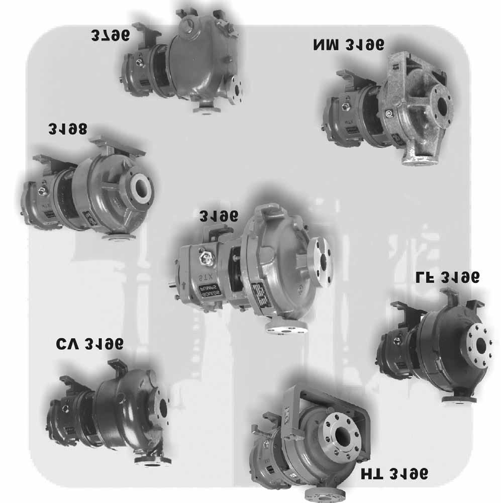
12 GENERAL INFORMATION PUMP DESCRIPTION PARTS COMMONALITY NAMEPLATE INFORMATION RECEIVING THE PUMP Storage Requirements Handling PUMP DESCRIPTION Model Pump Description Size Groups 3196 The model is based on 5 power ends and 29 hydraulic pump sizes. The 3196 is a horizontal overhung, open impeller, centrifugal pump that meets the requirements of ANSI B73.1. STX MTX LTX XLT-X X-17 No. of Sizes CV 3196 The model is based on four power ends and seven hydraulic pump sizes. The CV 3196 is a horizontal overhung, recessed impeller, centrifugal pump. It is specifically designed to handle bulky or fiberous solids, air or gas entrained liquids, or shear sensitive liquids. STX MTX LTX XLT-X HT 3196 The model HT 3196 is based on 4 power ends and 28 hydraulic pump sizes. The HT 3196 is a horizontal, centerline mounted, overhung, open impeller, centrifugal pump that meets the requirements of ANSI B73.1 STX MTX LTX XLTX LF 3196 The model is based on 3 power ends and 4 hydraulic pump sizes. The LF 3196 is a horizontal overhung, open impeller, centrifugal pump that meets the requirements of ANSI B73.1. It is designed specifically for low flow high head applications. STX MTX LTX NM 3196 The model is based on 2 power ends and 13 hydraulic pump sizes. The NM 3196 is a horizontal overhung, open impeller, centrifugal pump that meets the requirements of ANSI B73.1. It is made of a fiber reinforced vinylester to handle severe corrosives. STX MTX The model is based on 2 power ends and 4 hydraulic pump sizes. The 3198 is a horizontal overhung, open impeller, centrifugal pump that meets the requirments of ANSI B73.1. It is made of a Teflon lined ductile iron to handle severe corrosives. STX MTX The model is based on 3 power ends and 8 hydraulic pump sizes. The 3796 is a horizontal overhung, self priming, open impeller, centrifugal pump. STX MTX LTX ANSIFAM IOM - 7/04 11
13 This Page Intentionally Left Blank 12 ANSIFAM IOM - 7/04
14 ANSI Family Parts Commonality All of Goulds Pumps horizontal ANSI pumps are based on the same power end. All of the metallic units share the same stuffing box covers and seal chambers. The non-metallic units all have unique casings, impellers, and seal chambers. The chart on the following pages demonstrates the parts commonality and the relationship between the model lines. 2 ANSIFAM IOM - 7/04 13
15 Model Casing Impeller HT 3196 The casing is top centerline discharge and self-venting. The gasket is fully confined. An integral foot support is used for maximum resistance to misalignment and distortion from piping loads. ANSI flat faced serrated flanges are standard. ANSI class 150 raised face serrated, ANSI class 300 flat face serrated, and ANSI class 300 raised face serrated are available. The casing is top centerline discharge and self-venting. It has an integrally cast priming chamber that allows the pump to evacuate air to prime itself. The gasket is fully confined. An integral foot support is used for maximum resistance to misalignment and distortion from piping loads. ANSI class 150 raised face serrated flanges are available as an option. The casing comes with a provision to accept an immersion heater to keep the liquid in the priming chamber from freezing in outdoor applications. The casing is top centerline discharge, self-venting, and centerline mounted. The casing support is used for maximum resistance to misalignment and distortion from thermal piping loads. The centerline mounted casing maintains vertical alignment at elevated temperatures. ANSI class 300 raised face serrated flanges are standard. The impeller is fully open and threaded to the shaft. The threads are sealed from the pumpage by a Teflon O-ring for the 3196 and The HT 3196 uses a Graphite O-ring. CV 3196 The casing is tangential discharge and available with optional connections for venting, flushing, and solids cleanout. The gasket is fully confined. An integral foot support is used for maximum resistance to misalignment and distortion from piping loads. ANSI class 150 flat face serrated flanges are standard on all sizes. The impeller is fully open and recessed from the casing. It has curved vanes and is threaded to the shaft. The threads are sealed from the pumpage by a Teflon O-ring. LF 3196 The casing is top centerline discharge and self-venting. The gasket is fully confined An integral foot support is used for maximum resistance to misalignment and distortion from piping loads. ANSI class 150 rasied face serrated flanges are stanard on 4, 8, and 10 sizes. ANSI class 300 raised face serrated flange are standard on the 13 size and optional on 4, 8, and 10 sizes. The impeller is fully open with radial vanes and balance holes. The impeller is threaded to the shaft and sealed from the pumpage by a Teflon O-ring. NM 3196 The casing is top centerline discharge and self-venting. It is constructed from a fiber reinforced vinylester that is ribbed for strength. It is sealed using a Viton O-ring as standard. An integral foot support is used for maximum resistance to misalignment and distortion from piping loads. ANSI class 150 flat face flanges are standard. The impeller is fully open and threaded to the shaft. It is a fiber reinforced vinylester over a Hastelloy C insert that provides support and rigidity to the impeller while securing it to the shaft. The threads are sealed from the pumpage by a Teflon O-ring The casing is top centerline discharge and self-venting. The ductile iron casing is lined with PFA Teflon for corrosion resistance and is offered with ANSI class 150 raised face flanges. The casing gasket is a Teflon envelope with a compressible filler that provides a positive seal with low bolt torque. The impeller is fully open and threaded to the shaft. It is constructed of a PFA Teflon covered steel insert. The insert provides support and rigidity to the impeller while securing it to the shaft. The threads are sealed from the pumpage by a Teflon O-ring. 14 ANSIFAM IOM - 7/04
16 Cover / Chamber Power Ends 2 The 3196, CV 3196, HT 3196, LF 3196, and 3796 are available with a stuffing box cover designed for packing and BigBore or TaperBore PLUS seal chambers for improved performance of mechanical sales. An optional dynamic seal is available which uses a repeller to pump liquid out of the stuffing box while the pump operates. A static seal prevents leakage when the pump is shutdown. Frame Adapter - The ductile iron frame adapter has a machined rabbet fit to the seal chamber/ stuffing box cover and a precision dowel pin fit to the bearing frame. The 3198 frame adapter has the same features but different dimensions to accommodate the pump s Teflon lining. Power End - The oil level is viewed through a sight glass. Optional oil cooling is provided by a finned tube cooler. A finned tube cooler is standard with HT Flood oil lubrication is standard. The power end is sealed with non-metallic labyrinth seals. No machining is requried to convert from oil to grease or oil mist lubrication. Regresable bearings and oil mist lubrication are optional. Shaft - The shaft is available with or without a sleeve. When supplied with a Teflon sleeve, the 3198 shaft is knurled under the sleeve to provide a positive drive for the sleeve. The NM 3196 is supplied with a fiber reinforced vinylester backplate to accommodate a clamped outside single seal. The backplate is also available with an internal bypass flush. An optional bolt on seal chamber is available for conventional back-toback double seals. Bearings - The inboard bearing carries only radial loads. It is free to float axially in the frame. The outboard bearing is shouldered and locked to the shaft and housing to enable it to carry radial and thrust loads. All fits are precision machined to industry standards. The inboard bearing is a single row deep groove ball bearing. The outboard bearing is a double row angular contact bearing, except for the LTX which uses a pair of single row angular contact ball bearings mounted back-to-back. The 3196 is supplied with a PFA Teflon lined backplate to accommodate a clamped outside single seal. Also available for the backplate is a bolt-on metallic seal chamber for conventional back-to-back double seals. An optional PFA Teflon lined standard bore stuffing box cover is available for conventional single clamped seat inside or outside seals. For cartridge seals, an ETFE Tefzel lined BigBore seal chamber is available. ANSIFAM IOM - 7/04 15
17 NAMEPLATE INFORMATION Every pump has two Goulds nameplates that provide information about the pump. The tags are located on the casing and bearing frame. When ordering spare parts, you will need to identify pump model, size, serial number, and the item number of required parts. Information can be taken from the pump casing tag. Item numbers can be found in this manual. Description Fig. No. Example. Pump Casing Tag - provides information about the pump s hydraulic characteristics. Note the format of the pump size: Discharge x Suction - Nominal maximum Impeller Diameter in inches. (Example: 2x3-8) Fig. 1 English (Figs. 1&2). Fig. 2 Metric Bearing Frame Tag - provides information on the lubrication system used (Fig. 3). Fig. 3 ATEX Tag - If applicable, your pump unit may have the following ATEX tag affixed to the pump and/or baseplate. See the Safety section for a description of the symbols and codes (Fig. 4). Fig ANSIFAM IOM - 7/04
18 Inspect the pump as soon as it is received. Carefully check that everything is in good order. Make notes of damaged or missing items on the receipt and freight bill. File any claims with the transportation company as soon as possible. RECEIVING THE PUMP STORAGE REQUIREMENTS Short Term: (Less than 6 months) Goulds normal packaging procedure is designed to protect the pump during shipping. Upon receipt, store in a covered and dry location. 2 Long Term: (More than 6 months) Preservative treatment of bearings and machined surfaces will be required. Rotate shaft several times every 3 months. Refer to driver and coupling manufacturers for their long term storage procedures. Store in a covered dry location. Fig. 4 NOTE: Long term storage treatment can be purchased with the initial pump order or can be applied to pumps already in the field that were not treated at the factory. This service can be supplied by contacting your local Goulds sales representative. HANDLING WARNING Pump and components are heavy. Failure to properly lift and support equipment could result in serious physical injury or damage to pumps. Steel toed shoes must be worn at all times. Use care when moving pumps. Lifting equipment must be able to adequately support the entire assembly. Hoist bare pump using a suitable sling, under the suction flange and bearing frame. Baseplate mounted units are moved with slings under the pump casing and driver. Refer to Figs. 4-7 for examples of proper lifting techniques. WARNING Refer to the Installation section of this manual for detailed instructions for lifting a Polyshield ANSI Combo with installed equipment. Never lift a Polyshield ANSI Combo with pump and motor mounted using the procedure shown in Fig. 5 and Fig. 6. Fig. 5 Fig. 6 ANSIFAM IOM - 7/04 17
19 Fig. 7 NOTE: When lifting the NM 3196 or metallic units with integral suction flanges that do not have a way to secure the strap on the suction flange, the strap shown in Figures 4-6 around the suction flange should be secured around the frame adapter (Fig. 7). 18 ANSIFAM IOM - 7/04
20 INSTALLATION BASEPLATE INSPECTION SITE / FOUNDATION LEVEL BASEPLATE Cast Iron / PermaBase / Fab. Steel Feature Fab. Steel /Advantage Base Stilt Mounted Spring Mounted Polyshield ANSI Combo BASEPLATE LEVELING WORKSHEET ALIGNMENT Alignment Checks Alignment Criteria ALIGNMENT TROUBLESHOOTING GROUT BASEPLATE Alignment Check PIPING General Suction Piping Discharge Piping Final Piping Check Equipment that is to be installed in a potentially explosive environment must be done so in accordance with the following installation instructions. 1. Remove all equipment. 2. Completely clean the underside of baseplate. It is sometimes necessary to coat the underside of the BASEPLATE INSPECTION SITE / FOUNDATION baseplate with an epoxy primer. This may have been purchased as an option. 3. Remove the rust preventative solution from the machined pads with an appropriate solution. A pump should be located near the supply of liquid and have adequate space for operation, maintenance, and inspection. Baseplate mounted pumps are normally grouted on a concrete foundation, which has been poured on a solid footing. The foundation must be able to absorb any vibration and to form a permanent, rigid support for the pumping unit. The location and size of the foundation bolt holes are shown on the outline assembly drawing, provided with the pump data package. ANSIFAM IOM - 7/04 19
21 All equipment being installed must be properly grounded to prevent unexpected static electric discharge. This includes ensuring that the PFA lined pumps (Model 3198) and the non-metallic liquid end pumps (Model NM3196) are pumping fluids that are conductive. If not, a static electric discharge may occur when the pump is drained and disassembled for maintenance purposes. Foundation bolts commonly used are sleeve type (Fig. 8) and J type (Fig. 9). Both designs permit movement for final bolt adjustment. Fig Inspect foundation for dust, dirt, oil, chips, water, etc. and remove any contaminants. Do not use oil-based cleaners as grout will not bond to it. 2. Prepare the foundation in accordance with the grout manufacturer s recommendations. Fig. 8 LEVEL BASEPLATE CAST IRON/PERMABASE /FAB. STEEL 1. Place two sets of wedges or shims on the foundation, one set on each side of every foundation bolt. The wedges should extend.75 in. (20mm) to 1.50 in. (40mm) above foundation, to allow for adequate grouting. This will provide even support for the baseplate once it is grouted. 2. Remove water and/or debris from anchor bolt holes/sleeves prior to grouting. If the sleeve type bolts are being used, fill the sleeves with packing or rags to prevent grout from entering. 3. Carefully lower baseplate onto foundation bolts. 4. Level baseplate to within.125 in. (3.2mm) over length of the baseplate and to within.088 in. (1.5mm) over the width of the base by adjusting wedges. 5. A level should be placed across the pump mounting pads and the motor mounting pads. 6. Hand tighten the bolts. Fig. 11 Fig ANSIFAM IOM - 7/04
22 FEATURE FAB. STEEL / ADVANTAGE BASE (BASEPLATES PROVIDED WITH VERTICAL LEVELING ADJUSTERS) 1. Coat the jack screws with an anti-seizing compound to allow for easy removal after the grout has been cured. 7. Place the two levels on the pump pads, one lengthwise on a single pump pad, and another across the middle of both pump pads (Fig. 14). 2. Cut round circular plates from bar stock to set the jack screws on. The edges of the plates should be chamfered to reduce stress concentrations. 3. Set the baseplate on the foundation and use the four corner jack screws to raise the baseplate off the foundation 0.75" to 1.5". The two center jack screws should not be touching the foundation. Fig Place two machinist levels on the motor pads, one lengthwise on a single motor pad, and another across the ends of both motor pads (Fig. 13). 8. Level the pump pads as close to zero as possible, in both directions, by adjusting the jack screws. 9. Install the anchor bolts until they are hand tight. 10. Return the levels to the motor pads and check the level measurements. 11. Adjust the jack screws and anchor bolts, if necessary, until all level measurements are within the design requirements of in./ft. 12. When taking readings, center the level over the pad being measured. NOTE: The Baseplate Leveling Worksheet provided may be used when taking readings. Stilt Mounted Fig Fig. 13 NOTE: When using a machinist level, it is important that the surface being leveled is free of all contaminants, such as dust, to ensure an accurate reading. 5. Level the motor pads as close to zero as possible, in both directions, by adjusting the four jack screws. 6. Next, turn down the center jack screws so that they are resting on their metal discs on the foundation. 1. Raise or support the baseplate above the foundation or floor. Fig Determine the desired baseplate height above the floor, referenced to the stilt mounting flange. ANSIFAM IOM - 7/04 21
23 3. Set the bottom adjusting nuts and jamnuts on each stilt to the desired height. 4. Insert a washer between the bottom adjusting nut and the baseplate. 5. Install each stilt, holding it in place with another washer and the top adjusting nut. Finish by installing the top jam nut. 6. Once all four stilts have been installed, lower the unit making sure each stilt bolt head settles into its floor cup. 7. Level the baseplate while making final height adjustments. Adjust the baseplate height by loosening the top jam nut and adjusting nut. Change the height by moving the lower adjusting nut. When the baseplate is level, tighten the top adjusting nuts and then snug the lower and upper jam nuts. NOTE: Suction and discharge piping must be individually supported. The stilt mounted baseplate is not designed to support any static pipe loads. 5. Repeat steps 1 thru 4 for all the spring assemblies. 6. Once all the springs have been installed, lower the unit on to the foundation pads. NOTE: The foundation pads are supplied by the customer. They are to be micro-inch surface finish 316 stainless steel plate. 7. Level the baseplate while making final height adjustments. Adjust the baseplate height by loosening the top jam nut and adjusting nut. Change the height by moving the lower adjusting nut. When the baseplate is level, tighten the top adjusting nuts just enough to make sure the top springs are not loose in their followers and then snug the lower and upper jam nuts. NOTE: Suction and discharge piping must be individually supported. The spring mounted baseplates are designed to support piping loads developed by thermal expansion only. Spring Mounted 1. Raise or support the baseplate above the foundation or floor. Be sure to allow enough room under the baseplate to install the spring assemblies. 2. Set the bottom adjusting nuts on each spring stud to the desired height. 3. Insert a washer between the bottom adjusting nut and the spring follower. Install a spring and another follower. Install this subassembly from the bottom of the baseplate. 4. Install the upper half of the spring assembly consisting of a follower, a spring, another follower, and a flat washer. Now install the top adjusting nut and jam nut. Tighten finger tight. Fig ANSIFAM IOM - 7/04
24 Polyshield ANSI Combo Installation, Operation, and Maintenance Instructions Safety Considerations Several important general precautions are listed below: 1. Do not remove the Polyshield ANSI Combo from its shipping pallet until you are ready to hoist it onto its location. 2. Do not subject the Polyshield ANSI or Custom Combo to rough handling or unnecessary mechanical shock. 3. Do not attempt to lift the Polyshield ANSI Combo by any means other than that which is prescribed in these procedures. 4. Do not use hammer blows or other impact loading to adjust the positioning of the Polyshield ANSI Combo. Do not pry against the Polyshield mounting block when moving the motor during shaft alignment. 5. Do not attempt to transport, handle, or install a Polyshield ANSI Combo when ambient temperature is below -50 F (-45 C). 6. Do not operate a pump installed on a Polyshield ANSI Combo at process fluid temperatures in excess of 300 F (150 C) with polymer mounting pads and 500 F with alloy mounting pads unless prior approval from ITT Industries is obtained in writing. NOTE: Always coordinate installation activity with operations personnel, and follow all plant safety requirements and applicable safety and health laws, directives and regulations. Overview WARNING CAUTION Observance of proper handling procedures during installation is extremely important to prevent damage to the Polyshield ANSI Combo. While polymer concrete possesses inherent high strength, subjecting it to impact or bending loads through rough handling or improper lifting or mounting may result in irreparable damage to the Polyshield ANSI Combo as well as damage to the mounted equipment or injury to personnel. Application The polymer concrete material used in the manufacture of the Polyshield ANSI Combo has been formulated for application in a wide range of corrosive fluid handling services. The material is not, however, universally corrosion resistant. A comprehensive corrosion guide is available. (Refer to Pricebook Page It is strongly recommended that this bulletin be reviewed prior to specifying or installing a Polyshield Product. The Polyshield ANSI Combo is also suitable for application in a wide range of fluid process temperatures, specifically, -50 F to 300 F (-45 C to 150 C). Depending on the configuration of the pump that is to be mounted on the Polyshield, fluid process temperature in excess of 300 F (150 C) may be permissible. Contact your ITT Industries Goulds Pumps representative for assistance in determining acceptability of a specific application. Storage This section addresses the storage procedures for the Polyshield ANSI Combo only. When storing Polyshield ANSI Combos and pump assemblies, it is important that the proper storage procedures for the pump be observed as well. Refer to the Installation, Operation and Maintenance Instructions (IOM) for the particular Goulds pump that is mounted on your Polyshield product. Polyshield normal packaging is designed to protect the Polyshield ANSI Combo during shipment and handling from the time it is manufactured at the factory to installation at the end user s jobsite. If the Polyshield Combo is to be stored for a period of time prior to installation, it is recommended that the following procedures be followed: a. Leave the Polyshield ANSI Combo strapped to its wooden shipping pallet. b. Place the pallet on a solid, dry, level surface in a location where the ANSI Combo cannot be struck by passing fork trucks, falling objects, etc. Make sure the pallet does not rock. c. Do not stack heavy objects on top of the Polyshield ANSI Combo. 3 ANSIFAM IOM - 7/04 23
25 d. If the Polyshield ANSI Combo is to be stored in an outdoor location, cover the Polyshield completely with a tarpaulin or dark plastic sheeting to prevent UV degradation of the surface. NOTE: UV degradation (bleaching) of the polymer concrete is the normal result of exposure to sunlight. This phenomenon is purely a visible change in the color of the material, which in no way compromises the performance or corrosion resistance characteristics of the Polyshield. WARNING Do not attempt to stand a Polyshield on its end to make more efficient use of storage space. Neither the Polyshield Combo nor the strapping that holds the Polyshield Combo to its wooden pallet have been designed for vertical storage. Severe personal injury or death, as well as irreparable damage to the Polyshield Combo may result if the Combo tips over. Lifting Polyshield Combo Units and Polyshield Combo / Pump Assemblies CAUTION Polyshield units should be transported via fork truck to the area of their intended installation on the wooden pallets on which they were shipped. Never transport a Polyshield unit over a long distance or over rough terrain while suspended from slings. Only trained personnel should do lifting. Pumps and motors often have integral lifting eyes or eye bolts. These are intended for use in lifting the individual pieces of equipment. Do not use these features to lift a Polyshield Combo / pump assembly. Lifting The following procedures are recommended for lifting Polyshield ANSI Combo units: Polyshield with no mounted equipment: WARNING Do not install eyebolts in the Polyshield thread inserts for the purpose of lifting the base. This practice imposes lateral loads on the inserts which they were not designed to withstand. Remove the metal shipping straps that hold the Polyshield unit to the wooden pallet. Slip slings under each end of the Polyshield unit as a harness (Fig. A). Lift the Polyshield unit a few inches off the pallet and verify that it hangs reasonably level and that the slings are not prone to slipping out of position. WARNING Fig. A Keep hands and feet out from under the Polyshield unit during these steps. If slings slip and the unit tips over, severe personal injury or death may result, as well as irreparable damage to the Polyshield Combo. If the sling appears to be unstable, set the Polyshield unit back on the pallet and reposition the slings. After satisfactory slinging has been achieved, the Polyshield unit may be hoisted onto its foundation. Take care not to bump the unit against fixed objects or induce any unnecessary shock loads. Lower the unit slowly over the foundation using care to center the unit over the rebar cage. Place shim packs or wedges under the Polyshield unit at a minimum of eight total or (four [4] locations on each side) to allow for the removal of the slings. Twelve (12) total shim locations or (six [6] shim locations each side are required for Polyshield units exceeding 6 feet in length. Polyshield with installed equipment: Pump and motor installed: Remove the metal shipping straps that hold the Polyshield unit to the wooden pallet. Slip slings under each end of the Polyshield unit. This procedure is recommended up to the MTX or LTX pump units. All motors up to a 364T NEMA frame may be installed while mounted. Motor frame sizes 365Tor larger should be removed during locating and installation of the Polyshield ANSI Combo units. Check to see that the pump suction nozzle does not interfere with the lifting sling. If the pump creates interference, it should be removed. Lift the Polyshield ANSI Combo a few inches off the pallet and verify that it hangs reasonably level and that the slings are not prone to slipping out of position. 24 ANSIFAM IOM - 7/04
26 After satisfactory slinging has been achieved, the Polyshield ANSI Combo may be hoisted onto its foundation. Take care not to bump the unit against fixed objects or induce any unnecessary shock loads. Lower the unit slowly over the foundation using care to center the unit over the rebar cage. Place shim packs or wedges under the Polyshield unit at a minimum of eight total (or four [4] locations on each side) to allow for the removal of the slings. Twelve (12) total shim locations (or six [6] shim locations each side) are required for Polyshield units exceeding 6 feet in length. Installation General Description of the Polyshield ANSI Combo The Polyshield ANSI Combo is a solid, polymer concrete foundation and baseplate shell that is manufactured in versions that conform to accommodate ASME/ANSI B73.1 pumps. Polyshield ANSI Combo units are manufactured in five primary sizes with integral catch basins and removable motor mounting blocks. Metallic thread inserts are provided in the mounting surface for the particular combination of pump and motor that the Combo is intended. The metallic thread inserts on the pump end are available in 316SS (18.8 CrNi stainless steel), Alloy 20 (A744, CN-7M) and Hastelloy C 276 (A494, CW-6M). Multiple motor insert patterns are also available to accommodate more than one NEMA frame size. The standard thread insert material for the motor end is 316SS (18.8 CrNi stainless steel). Optional alloy pads are available instead of metallic inserts for requirements that call for /ft. and or process temperatures between 301 F and 500 F. Polyadjust Motor Block Adjuster System The Polyshield ANSI Combo utilizes as standard the unique Polyshield Polyadjust motor mounting system (Fig. B). This system is comprised of a one-piece polymer concrete motor mounting block having surface flatness and parallelism equivalent to machine steel blocks. The Polyadjust motor mounting block system incorporates the Polyloc Transverse Jack Bolt system. The Polyloc system provides transverse motor adjustment. The side-mounted adjusters allow for shaft alignment to critical tolerances with minimal disturbance of indicators. The adjusters make contact with a solid motor mounting block not the foot of the motor. Fig. B Polyshield ANSI and Custom Combos Installation Procedures (NEW CONSTRUCTION) 1. Remove laitance and form grease and oil from area where the Polyshield ANSI Combo will be located using mechanical means, abrasive blasting, or water blasting. Remove any loose debris including fins, aggregate, or any protruding objects around the perimeter of the area where the Polyshield ANSI Combo will rest. 2. Measure the outside dimensions of the Polyshield ANSI Combo and subtract 8 from both the width and length to determine the rebar maximum dimension, thus providing clearance from the side of the walls of the ANSI Combo. 3. Drill holes in the existing slab a minimum of four inches deep for doweling in the vertical rebar rods allowing a minimum of one inch clearance from the top of the interior of the Polyshield ANSI Combo. Space the rebar rods of 12 centers. Remove dust and debris from dowel holes and fill with epoxy adhesive for anchoring the rebar. 4. Allow the epoxy adhesive to cure, and then install horizontal rebar rods, tying in place with wire. 5. Place the Polyshield ANSI Combo over the rebar cage, making adjustments for proper elevation, orientation relative to piping centerlines. A qualified millwright should field verify proper position of the pump mounting pads relative to the centerline of the suction piping. Appropriate shims may be placed along the bottom edge of the Polyshield ANSI Combo to aid in leveling. Place shim packs or wedges under the Polyshield unit at a minimum of eight total (or four [4] locations on each side) to allow for the removal of the slings and metal lifting straps from each end. A minimum of twelve (12) total shim locations (or six [6] shim locations each side) are recommended for Polyshield units exceeding 7 feet in length. 3 ANSIFAM IOM - 7/04 25
27 6. Check and verify the dimensions again before the grouting procedure begins. 7. A low slump standard concrete mix is suitable for filling the Polyshield ANSI Combo in new construction. 8. Seal around the outside bottom perimeter of the Polyshield ANSI Combo with a fast setting hydraulic cement. Two brand name hydraulic cements are: Water Plug Hydraulic Cement and Dam-It Non Shrink Hydraulic Cement 9. Pour the concrete mixture through the grout fill port on the top of the Polyshield ANSI Combo using a concrete vibrator to ensure proper flow of the concrete. Do not over vibrate as excessive vibrating leads to larger aggregate settling which will result in a weak mix. 10. Pour the concrete to the bottom edge of the grout fill port. 11. Remove any loose debris from around edges of the grout fill port. 12. Seal grout fill port with grout port plug and Polyshield Seal Kit provided. 13. Install pump, motor, and attach lines. TOOLS FOR INSTALLATION Hammer drill with proper size bit Worm gear saw with diamond blade(if required) Rebar cutters (new installation) Concrete mixer Concrete vibrator Lifting device (for placing Polyshield Foundation) Hand tools Chipping hammer Pressure washer or abrasive blast rig as required Epoxy adhesive (for setting rebar into concrete slab new installation) Rebar tie wire Fast set cement Polyshield ANSI Combo Sealing Kit Epoxy Novolac (EN) Instructions Each Kit contains: Polyshield EN Resin Polyshield EN Hardener Stir Sticks LATEX Gloves Instruction Sheet MSDS Material Safety Data Sheet Application Instructions: The Polyshield EN Sealing Kit is intended for use in (1) bonding the plug into the grout hole at the top of the combo and (2) sealing and providing chemical resistance barrier around the perimeter of pump pad. 1. All surfaces to be bonded should be thoroughly cleaned and should be free of dust, oils and contaminants. Sand surfaces to be bonded prior to use. 2. Pour Polyshield EN Hardener into the Polyshield Resin can. Mix well with stir stick for about two minutes. 3. Apply to properly prepared surface by stir stick or putty knife. 4. Use MEK, Xylene solvents for cleaning tools and equipment and for lightly brushing surface to provide a smooth finish. Safety Precautions WARNING Resin and hardener components may be irritating to the eyes and skin on contact. Vapors may cause irritation of eyes and respiratory tract. Area must be ventilated. Wear protective clothing including gloves. For details safety information, refer to the Material Safety Data Sheets of these products. Polyshield ANSI Combo Sealing Kit Vinyl Ester (VE) Instructions Each Kit contains: Polyshield VE Resin Polyshield VE Hardeners #1 Stir Sticks LATEX Gloves Instruction Sheet MSDS Material Safety Data Sheet 26 ANSIFAM IOM - 7/04
28 Application Instructions The Polyshield VE Sealing Kit is intended for use in (1) bonding the plug into the grout hole at the top of the combo and (2) sealing and providing chemical resistance barrier around the perimeter of pump pad. 1. All surfaces to be bonded should be thoroughly cleaned and should be free of dust, oils and contaminants. Sand surfaces to be bonded prior to use. 2. Pour Polyshield VE Hardener #1 into the Polyshield VE Resin can. Mix well with stir stick for about two minutes. 3. Apply to properly prepared surface by stir stick or putty knife. 4. Use MEK, Xylene solvents for cleaning tools and equipment and for lightly brushing surface to provide a smooth finish. Safety Precautions WARNING Resin and hardener components may be irritating to the eyes and skin on contact. Vapors may cause irritation of eyes and respiratory tract. Area must be ventilated. Wear protective clothing including gloves. For details on safety information, refer to the Material Safety Data Sheets of these products. Polyshield is a registered trademark, U.S. Patent Nos , et. al, apply. Shelf Life and Storage Store resin and hardener in their unopened containers in a dry cool place away from open flames, heat or sources of ignition. Shelf life is limited to 60 days if stored in a cool, dry location. Polyshield Seal Kits provide sealant for every ANSI Combo. Polyshield Seal Kits are shipped with each ANSI Combo. Fastener Size and Recommended Torque Values Recommended Fastener Standard Fastener Nominal Size Torque 1 lb.-ft. SAE Torque values shown for SAE fasteners are based on dry threads at 75% of proof load for ASTM307 Grades A and B (SAE Grade 1) fasteners. For lubricated, plated, or PTFE coated threads, use 75% of torque values shown. 3 ANSIFAM IOM - 7/04 27
29 BASEPLATE LEVELING WORKSHEET 28 ANSIFAM IOM - 7/04
30 ALIGNMENT Alignment procedures must be followed to prevent unintended contact of rotating parts. Follow coupling manufacturer s coupling installation and operation procedures. WARNING Before beginning any alignment procedure, make sure driver power is locked out. Failure to lock out driver power will result in serious physical injury. To remove guard, refer to coupling guard assembly/ disassembly instructions. The points at which alignment is checked and adjusted are: Initial Alignment is done prior to operation when the pump and the driver are at ambient temperature. Final Alignment is done after operation when the pump and driver are at operating temperature. Alignment is achieved by adding or removing shims from under the feet of the driver and shifting equipment horizontally as needed. NOTE: Proper alignment is the responsibility of the installer and user of the unit. Accurate alignment of the equipment must be attained. Trouble-free operation can be accomplished by following the procedures in Appendix III. ALIGNMENT CHECKS Initial Alignment (Cold Alignment) Before Grouting Baseplate - To ensure alignment can be obtained. After Grouting Baseplate - To ensure no changes have occurred during grouting process. After Connecting Piping - To ensure pipe strains haven t altered alignment. If changes have occurred, alter piping to remove pipe strains on pump flanges. Final Alignment (Hot Alignment) After First Run - To obtain correct alignment when both pump and driver are at operating temperature. Thereafter, alignment should be checked periodically in accordance with plant operating procedures. NOTE: Alignment check must be made if process temperature changes, piping changes and or pump service is performed. ALIGNMENT CRITERIA Good alignment is achieved when the dial indicator readings as specified in the alignment procedure are:.002 in. (.05 mm) Total Indicated Reading (T.I.R.) or less when the pump and driver are at operating temperature (Final Alignment).0005 in. per inch of dial indicator separation for the reverse dial indicator or laser method when the pump and driver are at operating temperature (Final Alignment). NOTE: C-Face motor adapter installation insturctions and alignment criteria are detailed in Appendix V. During the installation phase, however, it is necessary to set the parallel alignment in the vertical direction to a different criteria due to differences in expansion rates of the pump and driver. Table 1 shows recommended preliminary (cold) settings for electric motor driven pumps based on different pumpage temperatures. Driver manufacturers should be consulted for recommended cold settings for other types of drivers (steam turbines, engines, etc.) 3 ANSIFAM IOM - 7/04 29
31 Pumpage Temperature Table 1 Cold Setting of Parallel Vertical Alignment Set Driver Shaft, Inches (mm) 3196 CV 3196 HT 3196 LF 3196 NM F (10 C).002 (.05) low.002 (.05) low (.05) low.002 (.05) low.002 (.05) low.002 (.05) low 150 F F (65 C).001 (.03) high.001(.03) high (.03) high.001(.03) high.001(.03) high.001(.03) high 250 F (120 C).005 (.12) high.005 (.12) high (.12) high.005 (.12) high.005 (.12) high.005 (.12) high 350 F (175 C).009 (.23) high.009 (.23) high (.23) high N/A.009 (.23) high.009 (.23) high 450 F (218 C).013 (.33) high.013 (.33) high (.33) high N/A N/A.013 (.33) high 550 F (228 C).017 (.43) high.017 (.43) high (.43) high N/A N/A.017 (.43) high 650 F (343 C).021 (.53) high.021 (.53) high (.53) high N/A N/A N/A 700 F (371 C).023 (.58) high.023 (.58) high (.58) high N/A N/A N/A NOTE: For the HT 3196, the cold setting of parallel vertical is 0.0 for all pumpage temperatures due to centerline mounting. ALIGNMENT TROUBLESHOOTING Table 2 Problem Problem Cause Remedy Cannot obtain horizontal (Side-to-Side) alignment, angular or parallel Driver feet bolt bound. Baseplate not leveled properly, probably twisted. Loosen pump hold down bolts and slide pump and driver until horizontal alignment is achieved. Determine which corner(s) of the baseplate are high or low and remove or add shims at the appropriate corner(s) and realign. 30 ANSIFAM IOM - 7/04
IMPORTANT SAFETY NOTICE
 IMPORTANT SAFETY NOTICE To: Our Valued Customers User safety is a major focus in the design of our products. Following the precautions outlined in this manual will minimize your risk of injury. ITT Goulds
Installation, Operation and Maintenance Instructions
 Installation, Operation and Maintenance Instructions 3996 IMPORTANT SAFETY NOTICE To: Our Valued Customers User safety is a major focus in the design of our products. Following the precautions outlined
Lenntech. Model Installation, Operation and Maintenance Instructions
 Installation, Operation and Maintenance Instructions Model 3996 Lenntech info@lenntech.com Tel. +31-152-610-900 www.lenntech.com Fax. +31-152-616-289 FOREWORD This manual provides instructions for the
SERIES PC INSTRUCTION AND OPERATION MANUAL
 MEGGA SERIES PC INSTRUCTION AND OPERATION MANUAL Models PCT and PCF Close-coupled and frame-mounted single-stage horizontal end-suction pumps. WARNING: Read this manual before installing or operating this
Installation, Operation and Maintenance Instructions. Model HS
 Installation, Operation and Maintenance Instructions Model HS 4 HS IOM 5/08 IMPORTANT SAFETY NOTICE To: Our Valued Customers User safety is a major focus in the design of our products. Following the precautions
Series Base mounted pump. Installation and operating instructions
 Series 4030 Installation and File No: 40.80 Date: june 25, 2015 Supersedes: 40.80 Date: october 10, 2009 contents General 4 Inspection 4 Installation - Series 4030 base mounted Pump 4 1.0 Location 4 2.0
Model 3600 API th Edition (ISO 13709)
") Installation, Operation and Maintenance Instructions Model 3600 API 610 10th Edition (ISO 13709) Pump Safety Tips Safety Apparel: Insulated work gloves when handling hot bearings or using bearing heater
Installation, Operation and Maintenance Instructions Model 3600 API 610 10th Edition (ISO 13709) Pump Safety Tips Safety Apparel: Insulated work gloves when handling hot bearings or using bearing heater
Installation, Operation, and Maintenance Instructions. Model 3501 Mixer
 Installation, Operation, and Maintenance Instructions Model 3501 Mixer FOREWORD This manual provides instructions for the Installation, Operation, and Maintenance of the Goulds Model 3501 Optimix Medium
Installation, Operation, and Maintenance Manual
 Goulds Pumps Installation, Operation, and Maintenance Manual Model LF 3196 i-frame Table of Contents Table of Contents Introduction and Safety...4 Introduction...4 Requesting other information...4 Inspect
Installation, Operation, and Maintenance Manual. Model 3196 i-frame
 Installation, Operation, and Maintenance Manual Model 3196 i-frame Table of Contents Table of Contents Introduction and Safety... 5 Introduction... 5 Safety... 6 Safety terminology and symbols... 6 Environmental
TABLE OF CONTENTS. Introduction. Part Description. Handling. Commissioning, Startup, Operation and Shutdown. Installation. Figures
 TABLE OF CONTENTS Introduction Introduction Safety Warranty Product Description General Description Part Description Nameplates Figures Figure 1: PWA Pump Figure 2: PWA Power End Cross Sectional Figure
PROJ. NO SECTION HYDRONIC PUMPS
 SECTION 23 21 23 HYDRONIC PUMPS PART 1 - GENERAL 1.1 RELATED DOCUMENTS A. Drawings and general provisions of the Contract, including General and Supplementary Conditions and Division 01 Specification Sections,
Installation, Operation and Maintenance
 Installation, Operation and Maintenance Model 3910 10th Edition (ISO 13709) FOREWORD This manual provides instructions for the Installation, Operation, and Maintenance of the Goulds Model 3910 Vertical
Installation, Operation and Maintenance Instructions. Model JC
 Installation, Operation and Maintenance Instructions Model JC This page intentionally left blank. 4 JC IOM 11/06 TABLE OF CONTENTS PAGE SECTION 7 SAFETY 11 GENERAL INFORMATION 1 2 13 INSTALLATION 3 17
AURORA 3500 SERIES MODEL 3550 ASME/ANSI B73.1 INDUSTRIAL PROCESS PUMPS
 AURORA 3500 SERIES MODEL 3550 ASME/ANSI B73.1 INDUSTRIAL PROCESS PUMPS WWW.AURORAPUMP.COM INDUSTRIAL PROCESS PUMPS AURORA 3500 SERIES Model 3550 ASME/ANSI B73.1 Industrial Process Pumps Capacities to GPM
Installation, Operation, and Maintenance Manual
 Industrial Process Installation, Operation, and Maintenance Manual Series PBV Plastic Lined Ball Valve Table of Contents Table of Contents Introduction and Safety...2 Safety message levels...2 User health
Installation, Operation, and Maintenance Manual. Model 3910
 Installation, Operation, and Maintenance Manual Model 3910 Table of Contents Table of Contents Introduction... 4 Introduction... 4 Safety... 5 Safety terminology and symbols... 5 Environmental safety...
PO Box 645, Stockton, Missouri, FAX superiorgearbox.com
 I000-7000-D0447-A 4/7/05 1 SAFETY PRECAUTIONS CAUTION Please read this entire document prior to operating the gear drive. Gear drive failure and / or injury to operators may be caused by improper installation,
Model 3550 ASME/ANSI B73.1M Industrial Process Pumps
 3500 Series Model 3550 ASME/ANSI B73.1M Industrial Process Pumps The Aurora Model 3550 was designed to perform in the toughest industrial applications whether in the chemical, petro-chemical, mining, pulp
Series Base mounted pump. Installation and operating instructions
 Series 4030 Installation and File No: 40.80 Date: december 12, 2016 Supersedes: 40.80 Date: july 27, 2016 contents General 4 Inspection 4 Installation - Series 4030 base mounted Pump 4 1.0 Location 4
DeZURIK " BAW AWWA BUTTERFLY VALVES WITH EPOXY-RETAINED SEAT
 DeZURIK 20 144" BAW AWWA BUTTERFLY VALVES WITH EPOXY-RETAINED SEAT Instruction D10373 April 2017 Instructions These instructions provide information about the 20 (250 F2 model only) and the 24-144 BAW
NORTHWESTERN UNIVERSITY PROJECT NAME JOB # ISSUED: 03/29/2017
 SECTION 23 2123 - PUMPS PART 1 - GENERAL 1.1 RELATED DOCUMENTS A. Drawings and general provisions of the Contract, including General and Supplementary Conditions and Division 01 Specification Sections,
AURORA Series MODEL 3560 ASME/ANSI B73.1M INDUSTRIAL PROCESS PUMPS
 AURORA 3500 Series MODEL 3560 ASME/ANSI B73.M INDUSTRIAL PROCESS PUMPS WWW.AURORAPUMP.COM AURORA 3500 Series Model 3560 ASME/ANSI B73.M Industrial Process Pumps Capacities to 7000 GPM (590 m 3 /hr) Heads
Goulds API th Edition/ISO nd Edition API OH3 Overhung. Vertical In-Line with Bearing Frame. An ITT Brand
 Goulds 3910 API-610 11th Edition/ISO 13709 2 nd Edition API OH3 Overhung. Vertical In-Line with Bearing Frame An ITT Brand 3910 Designed to Handle High-Temperature and High-Pressure Services of the Oil
Installation, Operation, and Maintenance Instructions. T Design. L Type Alternate - Suction in Barrel. Model VIC
 Installation, Operation, and Maintenance Instructions T Design L Type Alternate - Suction in Barrel Model VIC 4 VIC IOM 6/07 FOREWORD This manual provides instructions for the Installation, Operation,
DELTA O-RING CARTRIDGE SEAL ASSEMBLY AND INSTALLATION INSTRUCTIONS INTRODUCTION:
 DELTA O-RING CARTRIDGE SEAL ASSEMBLY AND INSTALLATION INSTRUCTIONS INTRODUCTION: These instructions are provided to familiarize the user with the seal and its use. The instructions must be read carefully
Installation, Operation, and Maintenance Manual
 Installation, Operation, and Maintenance Manual Goulds 3610 i-frame API 610 11th Edition ISO 13709 2nd Edition, API Type BB1 Single- Stage, Axially-Split, Between-Bearing Table of Contents Table of Contents
Operation & Maintenance Manual
 Magnatex 3575 Series Operation & Maintenance Manual Mechanical Seal ANSI Process Pumps Phone: 713-972-8666 inquiries@magnatexpumps.com Fax: 713-972-8665 www.magnatexpumps.com TABLE OF CONTENTS SECTION
SERIES G3DB/AG3DB ELEVATOR
 TM INSTRUCTIONS AND PARTS LIST SERIES G3DB/AG3DB ELEVATOR WARNING This manual, and GENERAL INSTRUCTIONS MANUAL, CA-1, should be read thoroughly prior to pump installation, operation or maintenance. SRM00059
Table of Contents. Product Description General description Nameplate information... 15
 Table of Contents Table of Contents Introduction and Safety... 4 Introduction... 4 Safety... 4 Safety terminology and symbols... 5 Environmental safety... 5 User safety... 6 Product approval standards...
RS Multi-Stage, Ring Section Pumps
 RS Multi-Stage, Ring Section Pumps Technical Specification Pages This page left intentionally blank. 1.0 Overview. The RS Series is Carver s multi-stage pump for fluids at moderate to high pressures. The
Goulds LF 3196 i-frame. Low Flow ANSI Process Pump with i-alert Patented Intelligent Monitoring
 Goulds LF 3196 i-frame Low Flow ANSI Process Pump with i-alert Patented Intelligent Monitoring 2 LF 3196 i-frame Low Flow ANSI Process Pumps Designed for Total Range of Industry Services Capacities to
Self-Priming Process Pumps with Patented Intelligent Monitoring. Lenntech
 Self-Priming with Patented Intelligent Monitoring Lenntech info@lenntech.com Tel. +31-12-61-9 www.lenntech.com Fax. +31-12-616-289 Goulds 3796 Self-Priming Designed for Total Range of Industry Services
SUGGESTED SPECIFICATIONS
 PART 1 - GENERAL 1.01 SCOPE A. Pumps to be supplied under this specification shall be of a severe duty, recessed cupped impeller design suitable for use in (SLUDGE, GRIT, ETC. APPLICATIONS) with a 20 year
Installation, Operation and Maintenance Instructions. Model 3935
 Installation, Operation and Maintenance Instructions Model 3935 IMPORTANT SAFETY NOTICE To: Our Valued Customers User safety is a major focus in the design of our products. Following the precautions outlined
PWA-IL B73.2 IN-LINE
 PWA-IL ANSI/ASME B73.2 IN-LINE PROCESS PUMP PWA-IL ANSI/ASME B73.2 IN-LINE PROCESS PUMP COMPETITIVE ADVANTAGES vs. Ductile Iron n High-strength, impact resistant liquid ends for improved durability and
Installation, Operation, and Maintenance Manual
 Goulds Pumps Installation, Operation, and Maintenance Manual Model 3296 EZMAG Table of Contents Table of Contents Introduction and Safety...4 Introduction...4 Requesting other information...4 Safety...4
KP-C Series. Close Coupled End Suction Centrifugal Pumps. Installation, Operation and Maintenance
 KP-C Series Close Coupled End Suction Centrifugal Pumps Installation, Operation and Maintenance PUMP MODEL NOMENCLATURE KP - 8 x 6 x 16 - E C - AI - BCM Pump Series Suction Pipe Size (in) Discharge Pipe
Installation, Operation, and Maintenance Manual
 Installation, Operation, 7200CB, API Type BB5 Barrel Multistage / ISO 13709 2nd edition / API 610 8th, 9th, 10th, 11th edition Table of Contents Table of Contents Introduction and Safety... 4 Introduction...
Installation, Operation and Maintenance Instructions
 Installation, Operation and Maintenance Instructions Model API 3171 THIS PAGE INTENTIONALLY LEFT BLANK 4 API3171 IOM 4/07 FOREWORD This manual provides instructions for the Installation, Operation, and
Installation, Operation, and Maintenance Manual
 Industrial Process Installation, Operation, and Maintenance Manual Series PBFV Plastic Lined Butterfly Valve - Lug and Wafer Style Table of Contents Table of Contents Introduction and Safety...2 Safety
Goulds 3181 High-temperature/Pressure Paper Stock/ Process Pumps
 High-temperature/Pressure Paper Stock/ Process Pumps Designed to Handle High Temperature and High Pressure Services of the Pulp & Paper Industries Capacities to 13,000 GPM (3000 m 3 /h) Heads to 410 feet
INSTRUCTION MANUAL AND PARTS LIST FOR PG/RG3D_-187, 218, 250 and 312 SERIES PUMPS
 INSTRUCTION MANUAL AND PARTS LIST FOR PG/RG3D_-187, 218, 250 and 312 SERIES PUMPS WARNING This Instruction Manual and General Instructions Manual, CA-1, should be read thoroughly prior to pump installation,
DELTA O-RING CARTRIDGE SEAL ASSEMBLY AND INSTALLATION INSTRUCTIONS INTRODUCTION:
 DELTA O-RING CARTRIDGE SEAL ASSEMBLY AND INSTALLATION INSTRUCTIONS INTRODUCTION: These instructions are provided to familiarize the user with the seal and its use. The instructions must be read carefully
PO Box 645, Stockton, Missouri, FAX superiorgearbox.com W D0446-A 4/1/05 1
 W000-7000-D0446-A 4/1/05 1 SAFETY PRECAUTIONS CAUTION Please read this entire document prior to operating the gear drive. Gear drive failure and / or injury to operators may be caused by improper installation,
Installation, Operation, and Maintenance Manual
 Industrial Process Installation, Operation, and Maintenance Manual Cam-Tite Ball Valve Table of Contents Table of Contents Introduction and Safety...2 Safety message levels...2 User health and safety...2
Installation, Operation, and Maintenance Manual. Models 3180, 3181, 3185, and 3186
 Installation, Operation, and Maintenance Manual Models 3180, 3181, 3185, and 3186 Table of Contents Table of Contents Introduction and Safety... 4 Introduction... 4 Safety... 5 Safety terminology and
BEARING FITS INCHES (MM)
") CASING- Visually inspect for signs of wear, corrosion, or pitting. The casing should be replaced if wear exceeds Ys" deep. Check gasket surface for signs of corrosion or irregularities. IMPELLER- Visually
CASING- Visually inspect for signs of wear, corrosion, or pitting. The casing should be replaced if wear exceeds Ys" deep. Check gasket surface for signs of corrosion or irregularities. IMPELLER- Visually
PWA-LF LOW FLOW ANSI PROCESS PUMP
 PWA-LF LOW FLOW ANSI PROCESS PUMP COMPETITIVE ADVANTAGES Carbon Steel vs. Ductile Iron n High strength, impact resistant Carbon Steel liquid ends for improved durability and pressure containment at no
PROCESS PUMPS MODEL V200 ANSI B73.2
 EAGLE PROCESS PUMPS V200 ANSI B73.2 POWER END Shaft Diameters Bearings Stuffing Box PUMP END Maximum Diameter Solids Minimum Casing Thickness Casing Corrosion Allowance Working Pressure Test Pressure
26 Series Stainless Steel 2-way Ball Valves
 1-800-899-0553 26 Series Stainless Steel 2-way Ball Valves Users Manual Installation, Operation, & Maintenance 1. General Precaution 1.1. Material Section Material deterioration is determined by the contained
Installation, Operation, and Maintenance Manual. Model 3296 EZMAG
 Installation, Operation, and Maintenance Manual Model 3296 EZMAG Table of Contents Table of Contents Introduction and Safety... 3 Introduction... 3 Safety... 3 Safety terminology and symbols... 4 Environmental
GT SERIES WET PRIME PUMPS SERVICE MANUAL
 SERVICE MANUAL BEFORE GETTING STARTED This manual is intended as a guide to disassembly and reassembly of a Pioneer Pump. It is to be used only by trained and experienced service technicians who are familiar
Instruction Manual & Parts List For H/G323FXFSX-500_ & 800_ Pumps With Flowserve Type BX Cartridge Seal
 TM Instruction Manual & Parts List For H/G323FXFSX-500_ & 800_ Pumps With Flowserve Type BX Cartridge Seal WARNING This Special Instruction Manual and General Instructions Manual, CA-1, should be read
PWA ANSI / ASME B73.1 PROCESS PUMP
 PWA ANSI / ASME B73.1 PROCESS PUMP COMPETITIVE ADVANTAGES Carbon Steel vs. Ductile Iron n High strength, impact resistant Carbon Steel liquid ends for improved durability and pressure containment at no
Installation, Operation and Maintenance Instructions
 Installation, Operation and Maintenance Instructions 3175 IMPORTANT SAFETY NOTICE To: Our Valued Customers User safety is a major focus in the design of our products. Following the precautions outlined
ANSI Centrifugal Process Pumps. 911 Series
 ANSI Centrifugal Process Pumps 9 Series WHAT IS AN ANSI PUMP In 977, the American National Standard Institue (ANSI) established criteria for centrifugal pumps in terms of dimension, chemical composition
Butterfly valves Figure 56 Installation & Maintenance Instructions
 KEYSTONE Please read these instructions carefully This symbol indicates important messages and safety instructions. Hazard potentials: disregarding of instructions improper use of product insufficiently
SECTION PUMPS GENERAL PUMPS PART RELATED DOCUMENTS
 SECTION 15160 - PUMPS PART 1 - GENERAL 1.01 RELATED DOCUMENTS A. Basic Requirements: Provisions of Section 15010, BASIC MECHANICAL REQUIREMENTS and Section 15030, ELECTRICAL REQUIREMENTS FOR MECHANICAL
Thomas Disc Couplings Installation and Maintenance Series 52 Sizes with classical disc pack TM (Page 1 of 10) DANGER!
 DANGER!") Thomas Disc Couplings Installation and Maintenance Series 52 Sizes 125-925 with classical disc pack TM (Page 1 of 10) This is the Original Document in English Language Figure 1-1. General Information Thomas
Thomas Disc Couplings Installation and Maintenance Series 52 Sizes 125-925 with classical disc pack TM (Page 1 of 10) This is the Original Document in English Language Figure 1-1. General Information Thomas
Goulds 3186 High-temperature/Pressure Paper Stock/ Process Pumps
 Lenntech info@lenntech.com Tel. +31-152-610-900 www.lenntech.com Fax. +31-152-616-289 Goulds 3186 High-temperature/Pressure Paper Stock/ Process Pumps Goulds 3186 Designed to Handle High Temperature and
Fire Protection. FP-XA End Suction
 Fire Protection FP-XA End Suction PRODUCT BULLETIN MODEL FP-XA END SUCTION CPS Model FP-XA End Suction pumps are used in a variety of fire fighting applications. These rugged and efficient centrifugal
High-Temperature and Pressure Paper Stock / Process Pump
 3186 High-Temperature and Pressure Paper Stock / Process Pump 3186 Designed to handle High-Temperature and High-Pressure services of the Pulp & Paper Industries. Capacities to 3000 m³/h (13,000 GPM) Heads
SUNDYNE LMC/BMC 311P / 331P. Instruction and Operation Manual. August 2007
 SUNDYNE LMC/BMC 311P / 331P Instruction and Operation Manual August 2007 Visit our website at www.sundyne.com COPYRIGHT All rights reserved. No part of this publication may be reproduced, stored in a retrieval
INSTALLATION, OPERATION, MAINTENANCE MANUAL FOR MANUALLY OPERATED STOP CHECK VALVE
 INSTALLATION, OPERATION, MAINTENANCE MANUAL FOR MANUALLY OPERATED STOP CHECK VALVE Page 1 of 13 1.1 General CHAPTER 1 - GENERAL INFORMATION This manual contains maintenance instructions with pertinent
1. Wiring Diagrams: Power, signal, and control wiring.
 Page 232123-1 SECTION 232123 - PART 1 - GENERAL 1.1 RELATED DOCUMENTS A. Drawings and general provisions of the Contract, including General and Supplementary Conditions and Division 01 Specification Sections,
PWA-LF LOW FLOW ANSI PROCESS PUMP
 PWA-LF LOW FLOW ANSI PROCESS PUMP COMPETITIVE ADVANTAGES Carbon Steel vs. Ductile Iron n High strength, impact resistant Carbon Steel liquid ends for improved durability and pressure containment at no
INSTRUCTION MANUAL AC2516 REVISION D INSTALLER: PLEASE LEAVE THIS MANUAL FOR THE OWNER S USE. Series 1580 In-Line Mounted Centrifugal Fire Pumps
 INSTRUCTION MANUAL AC2516 REVISION D INSTALLER: PLEASE LEAVE THIS MANUAL FOR THE OWNER S USE. Series 1580 In-Line Mounted Centrifugal Fire Pumps PUMP LOCATION Locate the pump so there is sufficient room
Air Operated Diaphragm Pumps Operating and Maintenance Instructions
 Product & Chemical Disclaimer The user must take responsibility in the selection of the products materials of construction. Empire Pumps Ltd will act in an advisory role and offer recommendations; however,
griswold 811 performance curves
 griswold 811 performance curves pump size rpm page # 1 1/2 x 1-6AA 1800 1 3600 1 3 x 1 1/2-6AB 1800 1 3600 1 3 x 2-6AC 1800 1 3600 1 LF 1 1/2 x 1-8AA 1800 2 3600 2 1 1/2 X 1-8AA 1800 2 3600 2 3 X 1 1/2-8AB
Model 3656/3756. Installation, Operation and Maintenance Instructions. Table of Contents. Owner s Information
 Installation, Operation and Maintenance Instructions Model 656/756 Owner s Information Please fill in information and give this booklet to homeowner. Warranty information is on page 12. Model Number: Serial
Installation, Operation, and Maintenance Manual. Model 3409
 Installation, Operation, and Maintenance Manual Model 3409 Table of Contents Table of Contents Introduction and Safety... 3 Introduction... 3 Safety... 4 Safety terminology and symbols... 4 Environmental
Bray/ VAAS Slurry Series Knife Gate Valve 760/762/765/766/767/768 Series Operation and Maintenance Manual
 Bray/ VAAS Knife Gate Valve 760/762/765/766/767/768 Series Table of Contents Definition of Terms 1 Safety Instructions 1 Introduction 2 Unpacking 2 Storage 2 Installation 3 Commissioning 3 Cylinder-Operated
DELTA STYLE 9500 CARTRIDGE SPLIT SEAL INSTALLATION INSTRUCTIONS INTRODUCTION:
 DELTA STYLE 9500 CARTRIDGE SPLIT SEAL INSTALLATION INSTRUCTIONS INTRODUCTION: The Type 9500 Cartridge Split Seal sets the standard in the evolution of split seal designs. It is well suited for the widest
GT-200 GATE VALVES PN16, Screwed end
 Document No. : MD-QO-04-281 Date : 2009/07 /17 Version : 1.0 GT-200 GATE VALVES PN16, Screwed end USER MANUAL Modentic Industrial Corporation 14F-1,No.57Taya Rd.,Taichung,Taiwan,R.O.C. Email:modentic@ms9.hinet.net
LOW PRESSURE BALANCED VALVE DIAPHRAGM BALANCED
 DIAPHRAGM BALANCED All Rights Reserved. All contents of this publication including illustrations are believed to be reliable. And while efforts have been made to ensure their accuracy, they are not to
Voltmaster Centrifugal Trash Pumps
 Voltmaster Centrifugal Trash Pumps Model TSP2, TSP3 and TSP4 Owner s Manual February 2011 Table of Contents 1 Introduction............................ 1 1.1 Read before using..................... 1 1.2
Installation Vertical Pump: Installation 'CM' and 'CDM' Style: Operation:
 Installation Vertical Pump: Gusher vertical end suction pumps with integral shaft is easily installed and put into service. With the one piece shaft design there is no couplings to align, no shims or no
TITAN FLOW CONTROL, INC.
 PREFACE: This manual contains information concerning the installation, operation, and maintenance of Titan Flow Control (Titan FCI) Wafer Style, Dual Plate Check Valves. To ensure efficient and safe operation
Keystone Series GR resilient seated butterfly valves GRW/GRL Installation and operation manual
 Before installation these instructions must be fully read and understood Important Before valves are installed or used the following actions are recommended. 1. Valves/parts have to be inspected and thoroughly
barmesapumps.com WHAT IS AN ANSI PUMP
 WHAT IS AN ANSI PUMP In 1977, the American National Standard Institue (ANSI) established criteria for centrifugal pumps in terms of dimension, chemical composition of the materials and safety specifications,
Goulds Small Capacity Double Suction Pump
 Goulds 3410 Small Capacity Double Suction Pump 3410 Double Suction Pumps Designed for a Wide Range of Industrial, Municipal, Capacities to 7,000 GPM (1591 m3/h) Heads to 550 feet (168 m) Temperatures to
Wilfley. Model. Technical Handbook. ASME B73.1 Chemical Processing Pump
 Wilfley Technical Handbook ASME B73.1 Chemical Processing Pump Model A7 Wilfley Model A7 Chemical Processing Pumps Wilfley hydraulic seal in actual operation. ASME B73.1 M-91 Wilfley s Model A7 pump series
Full View Flow Indicator
 Full View Flow Indicator Threaded and Flanged Process Connection Installation / Operation / Maintenance Manual P.O. Box 1116 Twinsburg, OH 44087 Phone: 330/405-3040 Fax: 330/405-3070 E-mail: view@ljstar.com
INSTRUCTION AND REPAIR MANUAL MODELS 341A, 342A AND 344A 6
 SECTION 6 ITEM 0 DATED JUNE 1998 SUPERSEDES ITEMS 1, 2, DATED MARCH 1992 INSTRUCTION AND REPAIR MANUAL MODELS 1A, 2A AND A 6 NOTE This repair manual is applicable to pump Models 1A, 2A and A. All photos
1/2" AIR DRIVEN DIAPHRAGM PUMP
 1/2" DRIVEN DIAPHRAGM PUMP OPERATION AND SERVICE GUIDE O-1225D NOV. 2008 Page 1 of 6 Refer to Bulletin P-605, Parts List P-9151 DRIVEN, DOUBLE DIAPHRAGM PUMP MANUAL Congratulations on purchasing one of
Goulds CV 3196 i-frame. Non-Clog Process Pump with i-alert Patented Intelligent Monitoring
 Goulds CV 3196 i-frame Non-Clog Process Pump with i-alert Patented Intelligent Monitoring CV 3196 i-frame Recessed Impeller Designed for Non-Clog Solids Handling Capacities to 27 GPM (61 m 3 /h) Heads
Installation, Operation, and Maintenance Manual. AF (6"-36") MXR Bearings
 MXR Bearings") Installation, Operation, and Maintenance Manual AF (6"-36") MXR Bearings Table of Contents Table of Contents Introduction and Safety... 4 Introduction... 4 Safety... 4 Safety terminology and symbols...
Installation, Operation, and Maintenance Manual AF (6"-36") MXR Bearings Table of Contents Table of Contents Introduction and Safety... 4 Introduction... 4 Safety... 4 Safety terminology and symbols...
INSTRUCTION MANUAL AND PARTS LIST FOR SERIES 8L-630J AND 630M WARNING
 INSTRUCTION MANUAL AND PARTS LIST FOR SERIES 8L-630J AND 630M WARNING READ CA-l AND TIDS INSTRUCTION MANUAL PRIOR TO INSTALLATION, OPERATION OR MAINTENANCE WARNING This Instruction Manual and General Instructions
PUMPS STEAM TURBINES BUILDING & FIRE WASTEWATER SERVICE PUMP CLINIC 15 MECHANICAL SEAL DESIGN, OPERATION AND MAINTENANCE PROBLEMS
 PUMP CLINIC 15 MECHANICAL SEAL DESIGN, OPERATION AND MAINTENANCE PROBLEMS In my seminars I teach that mechanical seals fail prematurely because: The lapped faces open A seal component becomes damaged In
INSTRUCTION MANUAL. for BUTTERFLY VALVES
 STD-BFV-MGA Revision 0 11/21/03 INSTRUCTION MANUAL for BUTTERFLY VALVES Flowserve U.S. Inc Flow Control Division 1900 South Saunders Street P.O. Box 1961 Raleigh, NC 27603 Phone: (919) 832-0525 FAX: (919)
CONTENTS. VIKING PUMP, INC. A Unit of IDEX Corporation Cedar Falls, IA USA SECTION TSM 710.1
 TECHNICAL SERVICE MANUAL industrial heavy duty motor speed pumps SERIES 4076 AND 4176 SIZES hle, ate and ale SECTION TSM 710.1 PAGE 1 of 8 ISSUE B CONTENTS Introduction....................... 1 Safety
End Suction Centrifugal
 M o d e l s 3 U / 3 U B End Suction Centrifugal Operating Instructions, Installation & Maintenance Manual Certified to NSF/ANSI 6, ANNEX G * NSF/ANSI 6 Annex G listed models: 3U EBARA International Corporation
4500C Series Vortex Pumps
 Section 009 Page 003 4500C Series Vortex Pumps Table of Contents 4500C Performance 2" x 2" - 4523C, Multiple Speed... 004 3" x 3" - 4523C, Multiple Speed... 004 4" x 4" - 4522C, Multiple Speed... 005 4"
Installation, Operation, and Maintenance Manual
 Installation, Operation, and Maintenance Manual API 6D Piston Check Valve - IOM: Installation, Operation and Maintenance Manual 1/16 Table of Contents 1 INTRODUCTION... 3 1.1 SCOPE... 3 1.2 DISCLAIMER...
Instruction Manual and Parts List (G323FHF 630M) with Flow Serve Type Q Seal
 with Flow Serve Type Q Seal") TM Instruction Manual and Parts List (G323FHF 630M) with Flow Serve Type Q Seal WARNING This Instruction Manual and General Instructions Manual, CA-1, should be read thoroughly prior to pump installation,
TM Instruction Manual and Parts List (G323FHF 630M) with Flow Serve Type Q Seal WARNING This Instruction Manual and General Instructions Manual, CA-1, should be read thoroughly prior to pump installation,
EN. 850 Filtrate Pumps. Technical Specification Pages
 850 17.01.EN 850 Filtrate Pumps Technical Specification Pages 850 Series Filtrate Pump 850 17.01.EN This page left intentionally blank. 1.0 Overview. The 850 is Carver s filtrate pump line designed for
PRESSURE REGULATOR BACK PRESSURE TO ATMOSPHERE WITH OUTSIDE SUPPLY
 PRESSURE REGULATOR BACK PRESSURE TO ATMOSPHERE WITH OUTSIDE SUPPLY All Rights Reserved. All contents of this publication including illustrations are believed to be reliable. And while efforts have been
Installation Procedures
 For the precision ball and roller bearings supplied by MRC Bearings, skill and cleanliness while handling, mounting and dismounting are necessary to ensure satisfactory bearing performance. As precision
INSTALLATION, OPERATION AND MAINTENANCE INSTRUCTIONS
 INSTALLATION, OPERATION AND MAINTENANCE INSTRUCTIONS Contents Section 1. General Observations... 2 2. Operation... 4 3. Control During Operation... 5 4. Trouble Shooting... 6 5. Maintenance... 7 Please