Franking system PostBase One Service documentation
|
|
|
- Lorena Garrison
- 6 years ago
- Views:
Transcription
1 Print system Andreas Nagel VST; ServDok_PostBase-One_Kap04_02_printer_system_003eng.docx Revision May, 10th/ 2016 page 1
2 Chapter 4.2 Printer System 1 MOTORS IN THE PRINTER SYSTEM 3 2 PIVOT ASSEMBLY POSITIONS 4 3 REMOVING THE CLEANING AND SEALING STATION (MTS) MTS maintenance Remove the Wiper Pad Remove Deflector Remove/Install the Rotary Encoder Find the values of the Rotary Encoder The measurement range of the Rotary Encoder Determine the resistance values for the upper and lower range Rotary Encoder adjustment 14 4 REMOVE THE PIVOT ASSEMBLY 17 5 REMOVE PENDRIVER BOARD WHEN PRINTER SYSTEM IS REMOVED 19 6 ADJUSTING THE SEALING POSITION 21 7 EXCHANGE THE FLEECE BEHIND THE FAN 22 Andreas Nagel VST; ServDok_PostBase-One_Kap04_02_printer_system_003eng.docx Revision May, 10th/ 2016 page 2
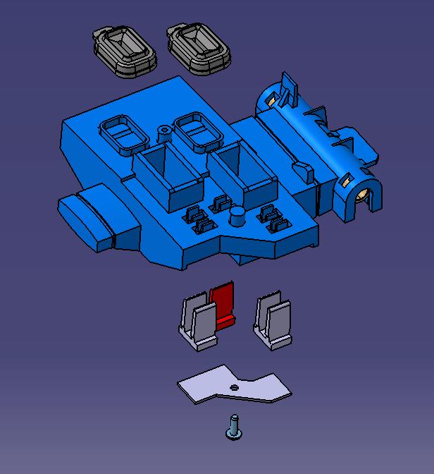
 is responsible for swinging the print-heads (cartridges) to their various positions")

![The second motor [2], the "MTS-Mover" (MTS, from "Maintenance Station" or "cleaning and sealing station"), moves the MTS](/docs-images/73/69334706/images/3-2.jpg "[4] forward and backward, wiping the print heads clean, clearing a path for the pivot assembly and bringing the sealing")
![caps into position under the print heads. [3] To manually pivot the assembly, use a slotted screwdriver. Caution!](/docs-images/73/69334706/images/3-3.jpg "Never turn with a socket wrench!")
3 1 MOTORS IN THE PRINTER SYSTEM The PostBase One printer system includes two motors. One motor [1] (the oscillating motor) is responsible for swinging the print-heads (cartridges) to their various positions (sealing, cleaning, blowing, and printing positions). A rotary encoder [3] directs the motor to these positions in steps defined by degrees of movement. The second motor [2], the "MTS-Mover" (MTS, from "Maintenance Station" or "cleaning and sealing station"), moves the MTS [4] forward and backward, wiping the print heads clean, clearing a path for the pivot assembly and bringing the sealing caps into position under the print heads. [3] To manually pivot the assembly, use a slotted screwdriver. Caution! Never turn with a socket wrench!! [2] [1] [4] Figure 1 To manually cause MTS-Mover motion use a slotted screwdriver MTS Motor Oscillating Motor Figure 2 Figure 3 Figure 4 Andreas Nagel VST; ServDok_PostBase-One_Kap04_02_printer_system_003eng.docx Revision May, 10th/ 2016 page 3
.")

 Figure 7 Deflector In print position, the deflector is swung out of")
.")
4 2 PIVOT ASSEMBLY POSITIONS When the machine is turned OFF or in "Stand-by" status, the print heads are in a sealed position to the MTS (Figures 5+6). Figure 6 Figure 5 Printhead position for flushing A cleaning cycle (flushing) into the deflector is carried out prior to every pivot into the printing position or after printing 500 franks. (Figure 7) Figure 7 Deflector In print position, the deflector is swung out of the way to the bottom, the MTS is in its rear-most position, and the print heads are aligned for printing (Figure 8). Figure 8 Andreas Nagel VST; ServDok_PostBase-One_Kap04_02_printer_system_003eng.docx Revision May, 10th/ 2016 page 4
 must first be removed.")
.")
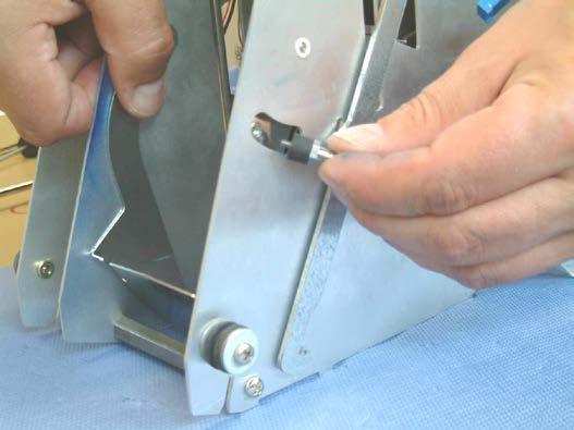
5 3 REMOVING THE CLEANING AND SEALING STATION (MTS) Whenever maintenance or repairs related to print quality are necessary, the cleaning and sealing station (MTS) must first be removed. To do this, manually drive the oscillating motor to move the print-heads away from the MTS (figure 9). Then manually turn the MTS motor to move the MTS from the sealing position into position for removal (figure 10). Figure 9 Removal position Sealing position Figure 10 Andreas Nagel VST; ServDok_PostBase-One_Kap04_02_printer_system_003eng.docx Revision May, 10th/ 2016 page 5


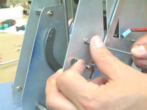
6 - Place the printer system on a stable surface as shown in figure Use a flat screwdriver to drive the MTS into its upper position, for easy removal (figure 12). Figure 11 Figure 12 In figure 13 the MTS can be seen in the cut-out in the middle wall. This is the upper position for removal. Figure 13 Andreas Nagel VST; ServDok_PostBase-One_Kap04_02_printer_system_003eng.docx Revision May, 10th/ 2016 page 6


.")

7 - Loosen the Phillips-screw and remove the holding plate (figure ) Figure 14 Figure 15 - withdraw MTS guidance axle (figure 16). - remove MTS (figure 17). Figure 16 Figure 17 Figure 18 Andreas Nagel VST; ServDok_PostBase-One_Kap04_02_printer_system_003eng.docx Revision May, 10th/ 2016 page 7


8 3.1 MTS maintenance Warning! The final version of the MTS is equipped with three wiper blades! - Use tweezers to remove the sealing caps. Clean or replace as needed. Figure 19 - Loosen the wiper-blade retaining plate Figure 20 - (3x) Remove wiper blades. Clean or replace as needed. Figure 21 Figure 22 Andreas Nagel VST; ServDok_PostBase-One_Kap04_02_printer_system_003eng.docx Revision May, 10th/ 2016 page 8
. Figure 23 Figure 24 3.")
 every time the heads swing into print position, or every 500 prints.")

.")
9 3.2 Remove the Wiper Pad - Move the print-heads into print position. - Now the wiper pad (for the wiper blades) can be removed and cleaned (figure 23). - The rubber wiper pads underneath the print-heads can be pushed off the axles if they need to be cleaned or replaced (figure 24). Figure 23 Figure Remove Deflector The deflector serves to protect the machine from excess ink released during the cleaning process necessary for the print-heads. The machine design calls for the print-head jets to be cleaned (flushed) every time the heads swing into print position, or every 500 prints. The cleaning process involves flushing the jets with ink. Before this is done, the deflector swings into position in front of the ink-jets to collect ink released in the flushing process. See figure 7, page 4 Figure 25 shows the deflector with ink deposits. It should be removed for cleaning. Figure 25 Figure 26 Attention! The final version of the printer system is to include an additional fan and filter in the side-wall (near the deflector, figure 26). This will help prevent ink spray from entering the machine's interior. Andreas Nagel VST; ServDok_PostBase-One_Kap04_02_printer_system_003eng.docx Revision May, 10th/ 2016 page 9
 - Use an 8 mm open-end spanner")

10 - Unhook the spring from the deflector (figure 27) - Use an 8 mm open-end spanner to remove the back-stop (figure 28+29). Figure 27 Figure 28 Figure 29 Andreas Nagel VST; ServDok_PostBase-One_Kap04_02_printer_system_003eng.docx Revision May, 10th/ 2016 page 10

 Figure 32")
11 - Remove the C-clips from the left and right hinge points. Figure 30 Figure 31 - Extract the deflector (figure 32) Figure 32 Andreas Nagel VST; ServDok_PostBase-One_Kap04_02_printer_system_003eng.docx Revision May, 10th/ 2016 page 11
.")
 (figure 34+35)")


12 3.4 Remove/Install the Rotary Encoder - Two Torx-screws must be loosened to remove the rotary encoder (figure 33). Figure 33 Engaging piece - When installing, make sure the engaging piece is in the correct position behind the plastic hook (nose) (figure 34+35) Figure 34 Engaging piece Figure 35 - Then re-insert the two screws and push the rotary encoder toward the front. Then tighten the screws lightly (figure 36) Figure 36 Caution! The encoder must be left loose! Andreas Nagel VST; ServDok_PostBase-One_Kap04_02_printer_system_003eng.docx Revision May, 10th/ 2016 page 12

13 3.5 Find the values of the Rotary Encoder The measurement range of the Rotary Encoder The Rotary Encoder can measure through a range of 95 (black zone). The steps of the angle are measured with a potentiometer. The possible resistance which you can measure is between 1.7 kω - 6 kω. All Rotary Encoders are individual and have a slightly different resistance for the upper and lower position! The Pivot Assembly can move in a max. angle of 85 (red zone). Using this method, the tolerance is 5 for the upper and lower position (if the adjustment is centred) Determine the resistance values for the upper and lower range Rotary Encoder PMR Figure 37 The first step is to use a multi meter and measure the resistance value in case of a released engaging arm. For this please follow these steps: - connect the red test prod to red cable and the black test prod to the green cable of the rotary encoder and note the resistance value (e.g. 5.8 kω). - now connect the red test prod to red cable and the black test prod to the yellow cable of the rotary encoder and note the resistance value for this again (e.g kω). If you measure the same value in case of a strained engaging arm, you will receive the same resistance values, however with reverse polarity of the test prods! Andreas Nagel VST; ServDok_PostBase-One_Kap04_02_printer_system_003eng.docx Revision May, 10th/ 2016 page 13


14 3.6 Rotary Encoder adjustment - Now place the rotary encoder in position (Torx IP 20; please use washers under the screws) Caution! Tighten the screws lightly. The encoder must be loose! Figure 38 - Leave the test prods connected and adjusts the resistance value which you have found before, by rotating the Encoder: Rotary Encoder released 0.1kΩ (Cartridge exchange position; upper mechanical end stop) Rotary Encoder strained + 0.1kΩ (print position; lower mechanical end stop) 5.8KΩ 5.7KΩ Place the Encoder in position, tighten the screws softly e.g. Rotary Encoder released 5.8 kω so adjust 5.7 kω or Rotary Encoder strained 1.81 kω so adjust 1.9 kω! KΩ 1.81KΩ - If the encoder is adjusted tighten up the screws. On print systems where this adjustment is already done in the factory, a little tag with the resistance values is fixed on the Encoder cables (figure 39). After the Encoder is adjusted, tighten up the screws Figure 39 Andreas Nagel VST; ServDok_PostBase-One_Kap04_02_printer_system_003eng.docx Revision May, 10th/ 2016 page 14
15 Andreas Nagel VST; ServDok_PostBase-One_Kap04_02_printer_system_003eng.docx Revision May, 10th/ 2016 page 15


16 - Put the flat ribbon cable in place. 1. release O-ring 2. place the cables 3. put the O-ring back in position Figure 40 - If you loosen the mechanical upper end stop, please make them tight again. Upper mech. end stop Figure 41 Attention! To place the end stop in position, the pivot assembly must be moved downwards and after you tighten the screw, please run the assembly back into the upper position and check the resistance values again. Andreas Nagel VST; ServDok_PostBase-One_Kap04_02_printer_system_003eng.docx Revision May, 10th/ 2016 page 16
.")
 Figure 43 - Now")

17 4 REMOVE THE PIVOT ASSEMBLY Before the pivot assembly can be removed, the end-stop must first be loosened and pushed aside (figure 42). Figure 42 - Then remove the O-ring from the rotary encoder in order to release the two flat-cables to the printhead (figure 43) Figure 43 - Now remove the inner C-clip on the pivot axle (figure 44) Figure 44 Andreas Nagel VST; ServDok_PostBase-One_Kap04_02_printer_system_003eng.docx Revision May, 10th/ 2016 page 17

 Figure 45 Figure 46 - Lift the pivot assembly up")

18 - Remove the two Phillips-screws from the pivot bearing. To remove the right screw, turn the gearsegment to that the cut-out aligns with the screw to give the screwdriver access (figure 45+46) Figure 45 Figure 46 - Lift the pivot assembly up and away (figure 47) Figure 47 Andreas Nagel VST; ServDok_PostBase-One_Kap04_02_printer_system_003eng.docx Revision May, 10th/ 2016 page 18
")
 Figure 48 Figure 49-4x Torx 8-screws")
 and remove cover (figure 51).")
.")
.")
19 5 REMOVE PENDRIVER BOARD WHEN PRINTER SYSTEM IS REMOVED - Release the end-stop and slide it to the left (figure 48) so that the print heads can be swung upward past the end-stop (figure 49) Figure 48 Figure 49-4x Torx 8-screws remove from the pen driver cover. Caution! Spring pressure! (Figure 50) and remove cover (figure 51). Figure 50 Figure 51 - Then remove the spacer pins (with springs). Attention: The left spacer pins are slightly longer (figure 52). Figure 52 Andreas Nagel VST; ServDok_PostBase-One_Kap04_02_printer_system_003eng.docx Revision May, 10th/ 2016 page 19
 and unplug the cables (figure 54).")
 When installing, make sure the upper edge of the board")

20 - Open the collars for the flat-cable plugs on the pen driver board (figure 53) and unplug the cables (figure 54). Figure 53 Figure 54 - Now the pen driver board can be extracted (figure 55) When installing, make sure the upper edge of the board is slipped under the protruding plastic tab. Figure 55 Andreas Nagel VST; ServDok_PostBase-One_Kap04_02_printer_system_003eng.docx Revision May, 10th/ 2016 page 20

 Figure 56 Figure 57 The indicator is linked to the MTS so that it moves")

21 6 ADJUSTING THE SEALING POSITION To adjust the sealing position, the machine must be in Service Mode. "Page 6 -> 3.5 Adjust MTS Printhead cap" Refer to Chapter 03 Service Mode When installed, it is not possible to see the MTS sealing station to check the position of the sealing caps on the print heads. Because these caps must be adjusted to within a tolerances measured in tenths of millimetres, a mechanical indicator with a 1 : 5 ratio has been provided. This indicator must be correctly positioned in the adjusting window under the cartridge flap (figure 56+57) Figure 56 Figure 57 The indicator is linked to the MTS so that it moves when the sealing station moves. The indicator's pivot point is located to that the opposite end of the indicator moves at a 5 : 1 when the sealing station moves. The sealing station is correctly adjusted when the indicator is in the middle of the adjustment hole. MTS-indicator pick-up Adjustment hole Figure 58 Print-head / Sealing cap position Andreas Nagel VST; ServDok_PostBase-One_Kap04_02_printer_system_003eng.docx Revision May, 10th/ 2016 page 21
 and a")


22 7 EXCHANGE THE FLEECE BEHIND THE FAN To protect the inside of the machine against ink dust, which is produced during any cleaning and spitting procedure, there is a fleece (filter) and a running fan implemented into the print system. This sucked ink dust is held in the filter fleece This fleece must be exchanged periodically during maintenance intervals (every 3 years or after imprints) (figure 59) Figure 59 For this remove 2 Torx screws (IP20) on the fan from the outside and disconnect the cable. (figure 60+61) Figure 60 Figure 61 You are now able to remove the fan including the filter channel to exchange the fleece. (figure 62+63) Figure 62 Figure 63 Note: During installation of the fan, please take care of the right direction (type plate visibly; see fig. 60), otherwise the ink dust becomes distributed into the machine! Andreas Nagel VST; ServDok_PostBase-One_Kap04_02_printer_system_003eng.docx Revision May, 10th/ 2016 page 22
TESLA MODEL S REAR UNDER SPOILER & DIFFUSER SYSTEM
 TESLA MODEL S Thank you for purchasing your Unplugged Performance Rear Under Spoiler & Diffuser System for the Tesla Model S! Please read this manual carefully prior to installation. REAR UNDER SPOILER
One- Touch Installation Instructions
 One- Touch Installation Instructions 1 1 Height Adjustable Pivot w/ screws 9 Upper Work Surface 2 Rail Mount Knobs 10 Back Cover 3 Transformer 11 Center Pivot w/ screws 4 Support Legs 12 Left Monitor Arm
Maintenance Information
 Form 16575334 Edition 1 April 2005 Electric Screwdrivers EL, EP and ET 34V DC Series Maintenance Information Save These Instructions WARNING Maintenance procedures have the potential for severe shock hazard
FlexJet - Flex Cable Replacement
 P/N: 109515R0 14140 NE 200th St. Woodinville, WA. 98072 PH: (425) 398-8282 FX: (425) 398-8383 FlexJet - Flex Cable Replacement Notices: Warning! Ensure that all AC power cables are removed from the printer
3D PRINTER. Pack 09. Anything you can imagine, you can make! 3D technology is now available for you at home! BUILD YOUR OWN
 BUILD YOUR OWN Pack 09 Anything you can imagine, you can make! 3D PRINTER Compatible with Windows 7 & 8 Mac OS X 3D technology is now available for you at home! www.model-space.com BUILD YOUR OWN 3D PRINTER
Fog Lamp Instructions
 Fog Lamp Instructions 2011+ Ford Super Duty Congratulations on your purchase of a high quality PUTCO product. Should you need any application or technical assistance feel free to call us at: 1-800-247-3974
INSTALLATION INSTRUCTIONS South Highway 11 Westminster, SC Toll Free (888) (864) FAX (864)
 (864) FAX (864)") 1.0 Purpose: To identify requirements for the replacement of ISS seals, o-ring and installation of gland nut to rod. 2.0 Scope: This instruction applies to the ISS units manufactured at Lift Technologies
1.0 Purpose: To identify requirements for the replacement of ISS seals, o-ring and installation of gland nut to rod. 2.0 Scope: This instruction applies to the ISS units manufactured at Lift Technologies
Auto Sentry-eXP Maintenance. Revised 12/21/07
 Auto Sentry-eXP Maintenance Revised 12/21/07 Maintenance Procedures for Auto Sentry exp Bill Dispenser Credit Card Reader Bill Acceptor Bill Dispenser Maintenance Bill Dispenser Problem / Cause Bill Dispenser
AmTryke Adult Recumbent Model JT2000 #50-FC-2000
 AmTryke Adult Recumbent Model JT2000 #50-FC-2000 TOOLS Needed for Assembly 5 mm Allen Wrench 8 mm Socket or Wrench 10 mm Socket or Wrench 14 mm Socket or Wrench 15 mm Socket or Wrench 22 mm Socket or Adjustable
FlexJet Carriage Circuit Board (PCB) Replacement
 Replacement") P/N: 111484 R0 14140 NE 200th St. Woodinville, WA. 98072 PH: (425) 398-8282 FX: (425) 398-8383 ioline.com FlexJet Carriage Circuit Board (PCB) Replacement Notices: Warning! Ensure that all AC power cables
P/N: 111484 R0 14140 NE 200th St. Woodinville, WA. 98072 PH: (425) 398-8282 FX: (425) 398-8383 ioline.com FlexJet Carriage Circuit Board (PCB) Replacement Notices: Warning! Ensure that all AC power cables
In area - A -, a proper seal must be made against the top of the window glass.
 Door window, adjusting Page 1 of 3 Audi > B3 > 1994-1998 Body Exterior, Interior 61 - Convertible top, checking and adjusting Door window, adjusting Sections C-C and D-D. Adjust door window so that window
TABLE OF CONTENTS. Ram Assembly
 TABLE OF CONTENTS DUC Cover------------------------------------------------------------------------------------ 00 Table of Contents----------------------------------------------------------------------------
AmTryke Adult Recumbent Model HP1000 #50-HC-1000
 AmTryke Adult Recumbent Model HP1000 #50-HC-1000 TOOLS Needed for Assembly 5 mm Allen Wrench 8 mm Socket or Wrench 10 mm Socket or Wrench 14 mm Socket or Wrench 15 mm Socket or Wrench 22 mm Socket or Adjustable
Z-Truck (Vertical Moving) Z-truck Flag. Y-Truck (Horizontal Moving) FIGURE 1: VIEW OF THE Z-TRUCK. Flexshaft Assembly
 Z-truck Flag. Y-Truck (Horizontal Moving) FIGURE 1: VIEW OF THE Z-TRUCK. Flexshaft Assembly") Checking and Replacing the AC Motor To remove and replace the AC Motor you will need the following tools: #2 Phillips screwdriver (magnetic tip preferred) Removing the AC Motor 1. Ready the machine by
Checking and Replacing the AC Motor To remove and replace the AC Motor you will need the following tools: #2 Phillips screwdriver (magnetic tip preferred) Removing the AC Motor 1. Ready the machine by
INSTALLATION & OWNER S MANUAL
 Rev. B, p. 1 of 25 INSTALLATION & OWNER S MANUAL POLARIS RANGER RCS (for models XP or HD) (for model years 2009-) cab without doors kit (p/n 1POLRCWD) cab with doors kit (p/n 1POLRC) doors only kit (p/n
HD BULL NOSE FRONT BUMPER FORD SUPERDUTY F PARTS LIST:
 PARTS LIST: 1 HD Bull Nose Bumper Assembly 1 Bumper Cover 1 Winch Tray Bracket Assembly 5 6mm Combo Button Head Bolts (cover) 2 3-hole Bracket Spacer Plates 1 Wrench (6mm Button Head) 2 Plastic Plugs for
C15C C15C. Page 1 of 20
 2 x Lid Front Hinge 1135 8 x M8 Bolt 8 x M8 Washer (3mm Thick) 4 x M6 Large washers 4 x M6 Spring washers 4 x M6 x 40mm Bolts 6 x M6 20mm Bolts 6 x M6 Washers 20 x Screws 2 x Lid mount gas strut bracket
Installation Manual TWM Performance Short Shifter Cobalt SS/SC, SS/TC, HHR SS, Ion Redline and Saab 9-3
 Page 1 Installation Manual TWM Performance Short Shifter Cobalt SS/SC, SS/TC, HHR SS, Ion Redline and Saab 9-3 Please Note: It is preferable to park on a flat surface, as you will have to engage and disengage
Installation instructions, accessories - Rear Seat Entertainment
 XC90 Section Group Weight(Kg/Pounds) Year Month 3 39 2004 10 XC90 2003, XC90 2004, XC90 2005, XC90 2006, XC90 2007, XC90 2008 Replaces issue: 2003 12 J3904620 Page 1 of 18 Required tools A0000162 A0000163
Marsh Shipping Supply Co. LLC. Marsh TD2100 Electric Taper Technical Manual
 Marsh Shipping Supply Co. LLC Marsh TD2100 Electric Taper Technical Manual 2 A wall-socket must be close to the product and readily accessible. The overall system is protected against overload by the branch
LA600 MultiPrinter. Field Service Manual. Order No.: ER-LA600-SV
 LA600 MultiPrinter Field Service Manual The information in this document is subject to change without notice and should not be construed as a commitment by. assumes no responsibility for any errors that
N/S= Not Shown Bold = Part available for purchase. Italic = Part not available for purchase, listed and shown for reference only.
 Media Rewind Upgrade Installation Instructions Prepare for Installation This kit includes the parts and documentation necessary to install the media rewind option kit into the 105SL printers. Read these
401B/1KDB CoolRite/FreezeRite Installation Manual I003
 401B/1KDB CoolRite/FreezeRite Installation Manual 99-16105-I003 Copyright 2011 by ALL rights reserved. Information in this document is subject to change without notice. Companies, names and data used in
CLUTCH CABLE REPLACEMENT GUIDE FOR THE FOLLOWING PRODUCTS 2004 ONWARDS
 1 Issue 2 CLUTCH CABLE REPLACEMENT GUIDE FOR THE FOLLOWING PRODUCTS 2004 ONWARDS Mountfield 460R PD Briggs & Stratton Sprint Engine. Mountfield 460R PD/ES Briggs & Stratton Quantum Engine. Mountfield 460R
5 Removal and replacement
 5 Removal and replacement This chapter describes the removal and replacement of field-replaceable units (FRUs) only. Removal and replacement strategy User-replaceable parts Covers Internal assemblies ENWW
3 Axles and brakes. 3.1 Function and construction of the axles Construction Function
 3 Axles and brakes 3.1 Function and construction of the axles 3.1.1 Function Each wheel has an independent suspension system in the axle body (1), so that individual wheel suspension is provided. The swinging
Cybex Arc Trainer Owner s & Service Manual. 7 - Service
 7 - Service Table of Contents......... iii Warnings/Cautions All warnings and cautions listed in this chapter are as follows:! WARNING: All maintenance activities shall be performed by qualified personnel.
GENUINE PARTS INSTALLATION INSTRUCTIONS
 GENUINE PARTS INSTALLATION INSTRUCTIONS 1. 2. 3. 4. DESCRIPTION: APPLICATION: PART NUMBER: KIT CONTENTS: Accent light Kit Versa Note 999F3 4Z000 - Accent Lighting Kit. 999Q9 AY000 - Accessory Service Connector
INSTALLATION INSTRUCTIONS ELEVATION FRONT BUMPER 2018 FORD F150
 INSTALLATION INSTRUCTIONS PARTS LIST: 1 Elevation Bumper Assembly 28 12mm x 37mm x 3mm Flat Washers 1 Driver/Left Frame Mounting Bracket 4 12mm Lock Washers 1 Passenger/Right Frame Mounting Bracket 12
Your G3 buggy is fitted with three switches on the front part of the body:
 CONTENTS Buggy operation... 3 General Maintenance... 5 Technical Maintenance... 6 Front wheel bearing replacement... 6 Rear wheel bearing replacement... 7 Chain replacement... 8 Chain Adjustment... 9 Brake
Installing the Flame Ionization Detector EPC Flow Control Manifold
 Installing the Flame Ionization Detector EPC Flow Control Manifold The FID EPC Flow Control Manifold kit can be used to replace any HP 6890 Series FID EPC flow control manifold. This kit contains: Kit
Installation Guide. Stowe Cargo Management System. Table of Contents
 Installation Guide Stowe Cargo Management System Table of Contents 1. Pre-Installation (Page 2) a. Notes, Installation Kit contents & Tools needed 2. How to Install the Stowe Cargo Management System (Pages
OPERATION AND PARTS MANUAL
 OPERATION AND PARTS MANUAL MODEL NUMBER : PART NUMBER : GTL 1110 1900-0510 SERIAL NUMBER : BAYNE MACHINE WORKS, INC. PHONE: (864) 288-3877 910 FORK SHOALS ROAD TOLL FREE: (800) 535-2671 GREENVILLE S.C.,
SCION tc STRUT TIE BAR Preparation
 SCION tc 2005 - STRUT TIE BAR Preparation Part Number: 00016-80440 Code: YY1 Kit Contents 1 1 DS Mount Plate 2 1 PS Mount Plate 3 1 Cross Bar 4 1 Hardware Bag Hardware Bag Contents 1 4 8mm Screws 2 4 8mm
PowerBook G4 Aluminum 17" GHz Clutch Hinges Replacement
 PowerBook G4 Aluminum 17" 1-1.67 GHz Clutch Hinges Replacement Written By: Andrew Bookholt ifixit CC BY-NC-SA www.ifixit.com Page 1 of 20 INTRODUCTION Replacing the clutch hinges also provides a new attached
Oreck Magnesium Series Service Manual. The Oreck Manufacturing Company
 Oreck Magnesium Series Service Manual The Oreck Manufacturing Company 08/2012 10/2011 The Oreck Manufacturing Company Contents Covering all Magnesium Upright Models Including: LW100, LW125, LW1000, AND
Maintenance Information
 16573321 Edition 3 February 2014 Air Grinder Series 61H Maintenance Information Save These Instructions Product Safety Information WARNING Failure to observe the following warnings, and to avoid these
Maintenance Information
 Form 16573321 Edition 1 July 2004 Air Grinder Series 61H Maintenance Information Save These Instructions Always wear eye protection when operating or performing maintenance on this tool. Always turn off
Section 5: Parts Replacement
 Section 5: Parts Replacement Should the STAR TRAC 4500 Treadmill experience a problem requiring replacement of a specific part, the following procedures will help and instruct in the replacement of major
EVO-1162 EVO Tailgate Tire Carrier
 EVO-1162 EVO Tailgate Tire Carrier Bill of Materials EVO-1162 Tailgate Tire Carrier Part number Description Quantity EVO-12161 EVO Tailgate Tire Carrier 1 EVO-12162 Bolt Plate 1 EVO-12163 Wheel Mount 1
TOYOTA TUNDRA BUMPER STEP ASSIST Preparation
 Preparation Part Number: PT392-34140 Kit Contents 1 1 Linkage Assembly 2 1 Mounting Bracket 3 1 Step Pad 4 1 Hardware Bag 5 1 Bumper Support Bracket 6 1 Bumper Re-enforcement Bracket Hardware Bag Contents
REVi RX-8 Intake. RX-8 REVi Intake System I PN Installation Instructions. Tools Required:
 RX-8 REVi Intake System PN 18299 Installation Instructions I-18299 Tools Required: Small/Stubby Phillips head screwdriver Small flat head screwdriver Medium Phillips head screwdriver 10mm socket and ratchet
RMK HANDLEBAR KIT P/N ; ; APPLICATION BEFORE YOU BEGIN KIT CONTENTS. Verify accessory fitment at Polaris.com.
 RMK HANDLEBAR KIT P/N 2883835; 2883836; 2883837 APPLICATION Verify accessory fitment at Polaris.com. BEFORE YOU BEGIN Read these instructions and check to be sure all parts and tools are accounted for.
GENUINE PARTS INSTALLATION INSTRUCTIONS
 GENUINE PARTS INSTALLATION INSTRUCTIONS 1. 2. 3. 4. DESCRIPTION: Accent light Kit APPLICATION: Infiniti JX (2013) PART NUMBER: 999F3 YY000 - Universal Accent Lighting Kit. KIT CONTENTS: Item QTY Description
Removing and installing trim panel
 Removing and installing trim panel vw-wi://rl/a.en-gb.a03.5106.29.wi::31914802.xml?xsl=3 1. oldal, összesen: 1 oldal Removing and installing trim panel Removing Carefully prise out trim panel -1- in direction
OPERATION AND PARTS MANUAL
 OPERATION AND PARTS MANUAL MODEL NUMBER : PART NUMBER : GRL 1110 1900-0540 SERIAL NUMBER : BAYNE MACHINE WORKS, INC. PHONE: 864.288.3877 910 FORK SHOALS ROAD TOLL FREE: 800.535.2671 GREENVILLE SC, 29605
Weekly T-Jet2 TM Maintenance Procedures January 2007 Ver1.3
 Weekly T-Jet2 TM - Maintenance Procedures Weekly T-Jet2 TM Maintenance Procedures January 2007 Ver1.3 As a T-Jet2 owner there is weekly maintenance that will need to be performed to ensure proper operation
Installation Guide Philips MP90 VHM Wall Mount Kit
 Installation Guide Philips MP90 VHM Wall Mount Kit The purpose of this guide is to describe the procedures for installing the MP90 VHM Wall Mount Kit. Table of Contents Section 1.0: Mounting the VHM-Series
*Patent Pending Design*
 *Shown with optional Angled Tire Mount Part # 94202 *Patent Pending Design* Components 1) Rear Bumper 1) Swingarm 1) Swingarm Stop Bracket 1) Assembly 1) Rear Door Plate 1) Lower 3rd Brakelight Bracket
Wheel Bearing Replacement Passat TDI
 Rear Bearing/hub assembly replacement This is a fairly straight forward process. Pictures are not necessary for most of this procedure for a person with skills to do this repair. Anyone who thinks they
WORK INSTRUCTION READ FIRST. IF IN DOUBT
 WORK INSTRUCTION PAGE 1 OF 9 FIELD CHANGE INSTRUCTION : TO CHANGE A BACK DOOR AND SIDE LIFT PROCEDURE: Step 1. How to remove and replace the rear door of a canopy. Step 2. How to remove the side lift up
BX7460P Allure Tow Bar Operator Manual & Installation Instructions. ALLURE Tow Bar (10,000 lb) Pintle Coupler
 Pintle Coupler") Operator Manual & Installation Instructions ALLURE Tow Bar (10,000 lb) Pintle Coupler Hooking Up to Towed Vehicle 1. Position the towing vehicle on a level surface with a straight driveway ahead and engage
Operator Manual & Installation Instructions ALLURE Tow Bar (10,000 lb) Pintle Coupler Hooking Up to Towed Vehicle 1. Position the towing vehicle on a level surface with a straight driveway ahead and engage
SECTION steering mechanism
 07-302.01/ 1 2011MR17 SECTION 07-302.01 GENERAL Description See Figure 1. The includes the steering wheel (1), the steering column, the miter box (3), the steering shafts (2 and 4), and the drag link (7).
INSTALLATION AND CUSTOMER CARE INFORMATION 80 SERIES & 90 SERIES TREATMENT STATIONS
 INSTALLATION AND CUSTOMER CARE INFORMATION 80 SERIES & 90 SERIES TREATMENT STATIONS Customer Service and Technical Support: 8:00 AM to 5:00 PM central (M-Th) 8:00 AM to 4:30 PM central (Fri) Phone: 800-257-7407
BODY-24, Late Model 944 ( and Newer) Dash Replacement
 Dash Replacement") BODY-24, Late Model 944 (1985.5 and Newer) Dash Replacement Introduction Replacing the dash in a late model 944 is not overly difficult. However, it is very tedious and a lot of patience is required. It's
BODY-24, Late Model 944 (1985.5 and Newer) Dash Replacement Introduction Replacing the dash in a late model 944 is not overly difficult. However, it is very tedious and a lot of patience is required. It's
TOYOTA TUNDRA BUMPER STEP ASSIST Preparation
 Preparation Part Number: PT392-34140 Kit Contents Item # Quantity Reqd. Description 1 1 Linkage Assembly 2 1 Mounting Bracket 3 1 Step Pad 4 1 Hardware Bag 5 1 Bumper Support Bracket 6 1 Bumper Re-enforcement
LOCKN LOAD. MAX VEHICLE ROOF LOAD RATING: 100KG (2 Leg Pairs) 150KG (3 Leg Pairs) TOTAL LOAD EQUALS WEIGHT OF ROOF RACKS + ACCESSORIES + CARGO
 150KG (3 Leg Pairs) TOTAL LOAD EQUALS WEIGHT OF ROOF RACKS + ACCESSORIES + CARGO") LOCKN LOAD TM GUTTER MOUNT KIT GUTTER MOUNT HEAVY DUTY ROOF RACK ATTACHMENT SYSTEM MAX VEHICLE ROOF LOAD RATING: 00KG ( Leg Pairs) 50KG (3 Leg Pairs) TOTAL LOAD EQUALS WEIGHT OF ROOF RACKS + ACCESSORIES
LOCKN LOAD TM GUTTER MOUNT KIT GUTTER MOUNT HEAVY DUTY ROOF RACK ATTACHMENT SYSTEM MAX VEHICLE ROOF LOAD RATING: 00KG ( Leg Pairs) 50KG (3 Leg Pairs) TOTAL LOAD EQUALS WEIGHT OF ROOF RACKS + ACCESSORIES
REPLACEMENT OF TRANSMISSION EXTENSION-CASE GASKET AND OUTPUT-SHAFT SEAL ON 95 XJ6
 D. Jensen 2006 Distribution: www.jag-lovers.com REPLACEMENT OF TRANSMISSION EXTENSION-CASE GASKET AND OUTPUT-SHAFT SEAL ON 95 XJ6 V. 1.0 June 2006 The Fine Print: The following is a summary of my experience
Amtryke Model AM-12 & AM-16
 Amtryke Model AM-12 & AM-16 Carton Contents Carefully remove and lay out all parts from the carton so as not to scratch or lose any parts or pieces. The shipping carton should contain the pictured items
Rekluse Motor Sports. The z-start Clutch CRF 250X. Installation Guide Copyright 2002 Rekluse Motor Sports z-start Revision RMS116 CRF 250X
 Rekluse Motor Sports The z-start Clutch CRF 250X Installation Guide Copyright 2002 Rekluse Motor Sports z-start Revision 3.000 RMS116 CRF 250X 191-216 Manual Revision: 103105 Rekluse Motor Sports, inc.
Volkswagen New Beetle Body - Exterior 64 Glass, Window regulators (Page GR-64)
") 64 Glass, Window regulators (Page GR-64) Flush bonded windows Body flange, preparing for glass installation Broken rear window, removing Cleaning off excess adhesive material Curing time Installation instructions
64 Glass, Window regulators (Page GR-64) Flush bonded windows Body flange, preparing for glass installation Broken rear window, removing Cleaning off excess adhesive material Curing time Installation instructions
Carousel Unit User Manual Replacing the Check Stand Motor
 Carousel Unit User Manual Replacing the Check Stand Motor 02/01/2017 1 Table of Contents Tools:... 3 Turn Off Power to the Unit:... 4 Remove Power Switch... 5 Remove Electric Eyes:... 6 Remove POS (Point-Of-Sale)
THE SERIES-E POWR Slider
 C.R. LAURENCE CO., INC. PATENT NO. 4,920,698 THE SERIES-E POWR Slider MODEL: EPC814S 2014+ CHEVY/GMC SILVERADO/SIERRA 1500 NAGS: DY90122PK5 ELECTRIC SLIDING REAR WINDOW 2014 + CHEVY/GMC SILVERADO/SIERRA
THIS PRODUCT IS FOR PROFESSIONAL LABORATORY USE ONLY USER'S MANUAL. WELLS ENGINE UNIT 230 VOLT Product No. U905, U906, U907, U908
 DENTAL, INC. TECHNICAL BULLETIN U807-022510 5860 FLYNN CREEK ROAD READ ALL INSTRUCTIONS P.O. BOX 106 BEFORE PROCEEDING COMPTCHE, CALIFORNIA, U.S.A. 95427 SAVE THIS FOR FUTURE REFERENCE THIS PRODUCT IS
Fuser. Fan. 1. Remove all covers (see Covers). 2. Disconnect the fan cable (callout 1) at the ECU.
. 2. Disconnect the fan cable (callout 1) at the ECU.") Fuser Several parts must be removed before you can remove the fuser. The following parts are included in this section about removing the fuser: Fan Duplex-drive gears/face-down gears Duplex solenoid Fuser
Fuser Several parts must be removed before you can remove the fuser. The following parts are included in this section about removing the fuser: Fan Duplex-drive gears/face-down gears Duplex solenoid Fuser
Assembly & Installation Instructions
 TM P R O D U C T S Assembly & Installation Instructions FOR 28 SERIES SNOWPLOW PIVOT ASSEMBLY AND FLOAT LIMITER 99103000 FOR SERIAL NUMBERS 28D100000 TO 28D100770 97100552A 1. THINK SAFETY, ALWAYS WEAR
Stowe Cargo Management System
 Installation Guide Stowe Cargo Management System Table of Contents 1. Pre-Installation (Page 2) a. Notes, Installation Kit contents & Tools needed 2. How to Install the Stowe Cargo Management System (Pages
CRESTLINE DAMPENING SYSTEM INSTALLATION INSTRUCTIONS. Ryobi 3302M Itek 3985 A.B. Dick 9985 X /99
 CRESTLINE DAMPENING SYSTEM INSTALLATION INSTRUCTIONS Ryobi 3302M Itek 3985 A.B. Dick 9985 X88-32 3/99 GENERAL INFORMATION ATTENTION CRESTLINE DAMPENER OWNER Accel Graphic Systems provides parts and service
Read these instructions thoroughly before attempting to install this option.
 Rewind Option Kit Installation Instructions This kit includes the parts and documentation necessary to install the Media Rewind option into the following printers: 0XiIIIPlus, 0 dpi 0XiIIIPlus, 00 dpi
PARTS LIST: ELEVATION BULL NOSE FRONT BUMPER FORD SUPERDUTY F
 PARTS LIST: 1 Elevation Bumper Assembly 2 8-1.25mm x 25mm Hex Bolts 1 Winch Tray Bracket Assembly 2 8-1.25mm x 16mm Hex Bolts 2 3-hole Bracket Spacer Plates 6 8mm x 24mm x 2mm Flat Washers 2 Plastic Plugs
393: Multimedia system for the rear seat Multimedia system for the rear seat
 393: Multimedia system for the rear seat S80 (07-), 2008, B8444S, TF-80SC AWD, L.H.D, YV1AH852881073834, 073834 4/1/2013 PRINT 393: Multimedia system for the rear seat Multimedia system for the rear seat
TOYOTA TUNDRA COLD AIR INTAKE Preparation SEQUOIA
 Preparation SEQUOIA 2008 - Part Number: PTR03-34070 (5.7L) PTR03-34072 (4.7L) Kit Contents: 5.7L Item # Quantity Reqd. Description 1 1 Lid: Air Filter 2 1 Inlet Pipe: 5.7L 3 1 Air Filter: TRD Conical 4
SL-C CODER PARTS LIST AND OPERATING INSTRUCTIONS. Marion, IL STK. NO , REV H, 03/11
 SL-C CODER PARTS LIST AND OPERATING INSTRUCTIONS Marion, IL STK. NO. 5800-099, REV H, 03/11 CONTENTS Installation 2 Operating Instructions 2-3 Maintenance 3 Problems & Corrections 4 Instructions for Mounting
Installation Instructions Supertop NX Twill
 Installation Instructions Supertop NX Twill Vehicle Application: Jeep Wrangler Unlimited 2007-current Part Number 54823 Installation Tips Before you begin installing your new Supertop NX Twill, please
Subaru Front Mount Intercooler Kit STI Subaru Front Mount Intercooler Kit STI
 Subaru Front Mount Intercooler Kit STI 2008-2014 715500 Subaru Front Mount Intercooler Kit STI 2008-2014 Congratulations on your purchase of the Subaru Front Mount Intercooler Kit STI 2008-2014. The following
Replacing a Load Cell in the 400 Series Force Plate
 Replacing a Load Cell in the 400 Series Force Plate Determining which load cell is faulty You will first need to determine which load cell is at fault. To do this you will need the XPV7 diagnostic software.
INSTALLATION INSTRUCTIONS
 INSTALLATION INSTRUCTIONS Accessory Application Publications No. SECURITY SYSTEM P/N 08E49-SDA-100 ACCORD 2- AND 4-DOOR AII 30666 Issue Date AUG 2005 PARTS LIST Hood switch harness Illustration of the
Short Shifter Installation Instructions For Miata, 6-speed Manual Transmission
 Short Shifter Installation Instructions For 2006-15 Miata, 6-speed Manual Transmission PART# 994-060 Required tools: 10mm deep socket Long extension Ratchet Small flathead screwdriver Phillips-head screwdriver
3M Overhaul Service Kit
 SERVICE INSTRUCTIONS FOR 3M 12,000 RPM 3 in. (77 mm) RANDOM ORBITAL SANDERS 3M Overhaul Service Kit The part number 20346, 3M Overhaul Service Kit, contains all the replacement parts that naturally wear
MAINTENANCE ROAD 2013 WHEELS TECHNICAL MANUAL
 2013 WHEELS TECHNICAL MANUAL ROAD CYCLOCROSS PISTA GROUPSET TYPE OPERATION REVISION DESCRIPTION ROAD GROUPSETS CONE / CUP MOVEMENT 002 1/2011 SERVICING FRONT HUB ASSEMBLY PRODUCTS ON WHICH THE PROCEDURE
ACCLAIM OPERATOR, PARTS, AND INSTALLATION MANUAL BX4330 ACCLAIM
 ACCLAIM OPERATOR, PARTS, AND INSTALLATION MANUAL BX4330 ACCLAIM Tow Bar Class III (5000 lb) 2 Inch Coupler TOWING PRODUCTS DIVISION Page 1 of 8 292-2205 4/23/09 SAFETY DO NOT INSTALL, OPERATE OR USE THIS
Installation Instructions for the EVO3 Height-Adjustable Ultimate Short Shifter
 Installation Instructions for the EVO3 Height-Adjustable Ultimate Short Shifter for 1992-2005 325, 323, 318 and 1986-1994 525, 528, 535, 540 5-speed models only. (part number USSE3 and USSE5) Thank you
INSTALL/REMOVAL INSTRUCTIONS: WINDOW LIFT MOTOR
 REMOVAL/INSTALL OF WINDOW REGULATOR (742-269) Ford Mustang 1996 2004 General Tech Tips: Use painter s tape rather than duct tape to secure window. It will not damage paint or leave sticky residue. A plastic
INSTALL/REMOVAL INSTRUCTIONS: WINDOW REGULATOR
 REMOVAL/INSTALL OF WINDOW REGULATOR (741-809) Pontiac Grand Prix Coupe 1997 2002, Chevrolet Monte Carlo 2000 05 General Tech Tips: Use painter s tape rather than duct tape to secure window. It will not
Steering Column. Disassembly. 1. Remove instrument panel cover and reinforcement from vehicle as described in this section.
 Page 1 of 14 Section 11-04A: Steering Column, Ranger 1997 Aerostar/Ranger Workshop Manual DISASSEMBLY AND ASSEMBLY Procedure revision date: 05/17/2000 Steering Column Disassembly 1. Remove instrument panel
LEXMARK C780 CARTRIDGE REMANUFACTURING INSTRUCTIONS LEXMARK C780 TONER CARTRIDGE
 LEXMARK C780 CARTRIDGE REMANUFACTURING INSTRUCTIONS LEXMARK C780 TONER CARTRIDGE REMANUFACTURING THE LEXMARK C780 BLACK & COLOR TONER CARTRIDGES First released in April 2008, the Lexmark C780 is based
GENUINE PARTS INSTALLATION INSTRUCTIONS
 GENUINE PARTS INSTALLATION INSTRUCTIONS 1. 2. 3. 4. DESCRIPTION: Accent light Kit APPLICATION: R42H (2011) PART NUMBER: 999F3 AW000 - Universal Accent Lighting Kit. KIT CONTENTS: Item QTY Description Service
INSTALLATION INSTRUCTIONS REPAIR SEAL KIT PowerSurvivor 40E
 INSTALLATION INSTRUCTIONS REPAIR SEAL KIT PowerSurvivor 40E PURPOSE OF THE KIT The Repair Seal Kit should be installed after 1000 hours of operation. It should be installed regardless of whether or not
GPS AutoSteer System Installation Manual
 GPS AutoSteer System Installation Manual John Deere MFWD AutoTrac Ready Supported Models 8225R 8245R 8270R 8295R 8320R 8345R PN: 602-0254-01-A LEGAL DISCLAIMER Note: Read and follow ALL instructions in
GPS AutoSteer System Installation Manual
 GPS AutoSteer System Installation Manual John Deere MFWD Valve Install Vehicles Supported Models 7200 7210 7400 7410 7600 7510 7700 7610 7800 7710 7810 PN: 602-0212-01-A LEGAL DISCLAIMER Note: Read and
Caring for your car. Fig 28.Tyre pressure reading (arrowed).
.") Caring for your car Remove the dust cap from the valve in the rim of the wheel. Ensure the extension is fully into the gauge and push the gauge onto the valve, as in Fig 28. Allow the gauge to extend.
Caring for your car Remove the dust cap from the valve in the rim of the wheel. Ensure the extension is fully into the gauge and push the gauge onto the valve, as in Fig 28. Allow the gauge to extend.
Rekluse Motor Sports. The z-start Clutch CRF 250R. Installation Guide Copyright 2002 Rekluse Motor Sports z-start Revision RMS112 CRF 250R
 Rekluse Motor Sports The z-start Clutch CRF 250R Installation Guide Copyright 2002 Rekluse Motor Sports z-start Revision 3.000 RMS112 CRF 250R 191-212 Manual Revision: 091205 Rekluse Motor Sports, Inc.
DB4604 GMR-SD and GMR40-SD Disc Brake Caliper - Spring Applied, Air Released
 DB464 GMR-SD and GMR4-SD Disc Brake Caliper - Spring Applied, Air Released Nominal dimensions given. For specific dimensions please contact Twiflex Limited. For GMR Mk 2 caliper details see DB 364 Air
TOYOTA RAV4/HV INTERIOR LIGHT KIT Preparation
 Preparation Part Number: PT413-42130 Kit Contents Item # Quantity Reqd. Description 1 1 Wire Harness 2 3 Hardware Bag Contents Item # Quantity Reqd. Description 1 20 Cable Tie 2 2 Scotchlok 3 2 Foam Pad
Installation Instructions COMPETITION/PLUS SHIFTER Ford Mustang MT82 6-Speed Manual Transmission Catalog#
 Installation Instructions COMPETITION/PLUS SHIFTER 2015-2017 Ford Mustang MT82 6-Speed Manual Transmission Catalog# 3916037 Rev. 00 WORK SAFELY! For maximum safety, perform this installation on a clean,
PARTS TOOLS. Set Screw. Washer (2) Blue Bushing (2) Black Bushing (2) B&M Short Throw Shifter. Jam Nut Grease. Retaining Ring (2) Insert (2)
 Blue Bushing (2) Black Bushing (2) B&M Short Throw Shifter. Jam Nut Grease. Retaining Ring (2) Insert (2)") Installation Instructions SHORT THROW SHIFTER Fits: Porsche Boxter, Boxter S, 911, 996 Cayman & Cayman S models See Application Guide for specific year ranges and engine sizes Catalog # 45135 WORK SAFELY!
Installation Instructions SHORT THROW SHIFTER Fits: Porsche Boxter, Boxter S, 911, 996 Cayman & Cayman S models See Application Guide for specific year ranges and engine sizes Catalog # 45135 WORK SAFELY!
TOYOTA TRUCKS / SUVs COLD AIR INTAKE Section I Installation Preparation. 4.0L V6 (1GR-FE) Part Number(s): PTR
 Part Number(s): PTR") Section I Installation Preparation Part Number(s): PTR05-35061 Kit Contents Item # Quantity Reqd. Description 1 1 Intake Tube 2 1 Air Filter Housing 3 1 TRD Air Filter w/ #096 clamp 4 1 Adapter, Filter
Section I Installation Preparation Part Number(s): PTR05-35061 Kit Contents Item # Quantity Reqd. Description 1 1 Intake Tube 2 1 Air Filter Housing 3 1 TRD Air Filter w/ #096 clamp 4 1 Adapter, Filter
Fitting Instructions. Revo MQB Golf/GTi/Octavia/Leon Intercooler. Recommended Tools. Contents RV581M Dealer installation advised.
 RV581M100100 Recommended Tools Contents No. Description Tools Size Intercooler Torx Bit T25, T30 Bracket Kit llen Key 4, 5 mm Silicone Hoses Socket 7, 10, 16, 19 mm Hose Clamps Flat Head Screwdriver Small,
D40C HINGE # x Support Plate x M8 Bolt 8 x M8 Washer 6 x M6 20mm Bolts 6 x M6 Washers 19 x Screws
 HINGE # 1017 2 x Support Plate 1018 8 x M8 Bolt 8 x M8 Washer 6 x M6 20mm Bolts 6 x M6 Washers 19 x Screws 2 x Lid mount gas strut bracket 1041 2 x Self tap strut mount 1040 1 x Central Lock bracket 1510
Part Numbers: TTU-BGP14 & TTU-BGB14
 Date: 10.14.2015 TOYOTA TUNDRA 2014-17 Billet Grille Part Numbers: TTU-BGP14 & TTU-BGB14 Grille Hardware Bag Contents Item # Quantity. Description 1 6 U-Nuts 2 8 #10 Screws 3 2 #8 Screws 4 2 2 Flange Brackets