Please Read Important Safety Information
|
|
|
- Sydney Williamson
- 6 years ago
- Views:
Transcription


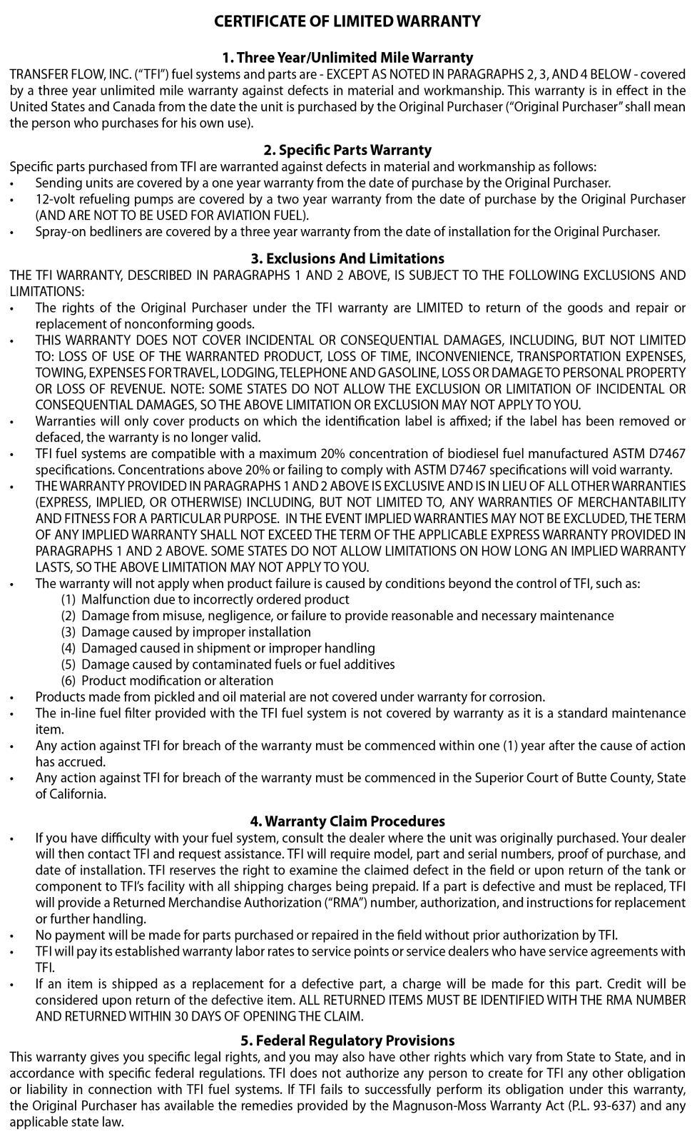
1


2 Please Read Important Safety Information Filling the Fuel Tank Never fill a fuel tank near a flame or ignition source which might ignite the fuel vapors. Avoid breathing fuel vapors or allowing the fuel vapors or liquid to contact the skin. Always fill fuel tanks while the vehicle is on a flat surface with the engine OFF. Open the fuel cap slowly to allow any pressure to escape. Never overfill or top-off any fuel tank. Overfilling the tank may cause damage to the emissions system, cause dangerous spills and possibly result in a fire. Never siphon fuel using the mouth. This practice is dangerous and potentially fatal. Use an appropriate pump. Do not allow fuel to contaminate soil or waterways. Properly contain and dispose of spilled fuels and cleanup materials. Other Important Safety Information Only use Transfer Flow replacement parts. Many parts of our fuel system appear common, but are in fact special parts which are critical for safe operation. Contact Transfer Flow, Inc. for parts. Disconnect the battery before working on the fuel system. Only use gas or diesel in our auxiliary fuel systems. A maximum concentration of 20% biodiesel fuel is compatible with Transfer Flow fuel systems. Do not grind, torch, weld, cut, or modify a Transfer Flow fuel system. Never over pressurize a fuel tank. Do not sleep in the bed of the pickup with a camper shell that contains one of our in-bed fuel systems. NEVER connect a Transfer Flow fuel system to a previously modified fuel system without contacting Transfer Flow. Do not smoke near a fuel system. This fuel system is not to be used in any manner intended or in connection with aircraft.
3 Part 1 Understanding the Operation of the MaxFlo-TFI System We d like to introduce you to MaxFlo-TFI, Transfer Flow s auxiliary operating fuel system. Please read this user s guide to better understand MaxFlo-TFI. We hope you enjoy your Transfer Flow auxiliary system! What is included in a MaxFlo-TFI auxiliary system? The MaxFlo-TFI auxiliary system includes an auxiliary tank, an auxiliary fuel pump, a wire harness, all necessary fuel lines, and mounting hardware for a complete installation. Also included is the MaxFlo-TFI computer controlled module. How does the MaxFlo-TFI auxiliary system operate? The MaxFlo-TFI auxiliary system feeds fuel into the vent tube of the original equipment manufacturer (OEM) tank by way of the Transfer Flow computer controlled fuel pump. The stock MaxFlo-TFI computer controlled module is completely automatic. It is NOT a dash mounted display or switch.* As the vehicle consumes fuel from the OEM tank, the MaxFlo-TFI auxiliary system automatically pumps fuel into the OEM tank until the OEM tank reaches 3/4 of a tank. If the user drives an extended time without refueling, the auxiliary system will start to run low on fuel. At which point the OEM gauge will fall below 3/8 of a tank indicating the auxiliary system is finally empty. *See page 6 for information on the dash-mounted Digital Lightbar upgrade kit, which includes an auxiliary fuel gauge and pump power button.

4 Figure 1: OEM Fuel Gauge Operation Fuel Transfer Range indicates when fuel will be transferred from the auxiliary tank to the OEM fuel tank. How often does the MaxFlo-TFI auxiliary system fill the OEM fuel tank? The MaxFlo-TFI computer module monitors the fuel level in the OEM fuel tank. When the fuel level on the OEM fuel gauge reads approximately 1/2, between 3/8 and 5/8 of a tank (see Figure 1), the MaxFlo-TFI auxiliary system will automatically start the transfer of fuel to the OEM tank. The auxiliary pump will continue to transfer fuel until the OEM fuel gauge registers 3/4 of a tank. This process is repeated until the auxiliary tank is empty.* *When stopping to refuel, always fill the OEM fuel tank first, and be sure the capacity is past 3/8 of a tank. If the OEM fuel tank is not filled within Fuel Transfer Range (Figure 1) then there is a chance that the auxiliary tank will not transfer fuel.

5 Figure 2: Fuel Transfer Range Within the OEM Gauge Fuel transfer range is subject to change based on many different factors. As long as the OEM gauge is registered between 3/8 and 5/8 of a tank, then the MaxFlo-TFI system will operate correctly. What do I need to do to operate the MaxFlo-TFI fuel system? The operation of the MaxFlo-TFI computer module is transparent to the user. There is not a dash mounted display or switch. Instead, the computer module is mounted under the auxiliary tank cover box. When the user keys on the vehicle, the system will automatically start working and pumping fuel if the OEM fuel gauge is in Fuel Transfer Range (Figure 2).
6 Why does Fuel in the OEM tank need to be more than 3/8 of a tank for the auxiliary system to operate correctly? Keeping the OEM tank above 3/8 will ensure that the MaxFlo-TFI auxiliary system will operate correctly. If the OEM tank is below 3/8 of a tank there is a chance that the Fuel Transfer Range (Figure 1 and 2) will not be recognized by MaxFlo-TFI. The system will read as if the auxiliary tank is empty and the fuel in the auxiliary tank will not be transferred. Example of operation for the MaxFlo-TFI auxiliary system: The user is driving down the road with a full OEM tank and also a full MaxFlo-TFI auxiliary tank. After driving for some time, the OEM fuel tank is at 1/2 capacity and in Fuel Transfer Range (Figure 1 and 2). The MaxFlo-TFI auxiliary pump turns on and transfers fuel into the OEM tank until the OEM gauge reads 3/4 of a tank again. As the user continued to drive down the road, the system continued to transfer fuel whenever the OEM gauge is in Fuel Transfer Range. After driving for an extended time, the user now notices the OEM gauge is at 3/8 of a tank. The OEM gauge is now out of Fuel Transfer Range so the user knows that the auxiliary tank is empty, and decides to stop to refuel. The user decides to only refuel the MaxFlo-TFI auxiliary tank, and not fill his OEM tank that is at 3/8 of a tank. The user gets back on the road, but notices that the MaxFlo-TFI auxiliary system is not transferring fuel back into the OEM tank. The user remembers that when the OEM gauge is below the Fuel Transfer Range The MaxFlo-TFI auxiliary system will not pump fuel. At the next stop the user fills the OEM tank from 3/8 to 1/2 of a tank. The MaxFlo- TFI system now is in Fuel Transfer Range and operates correctly.
7 Part 2 Monitoring the Fuel System How can I determine the fuel level of my MaxFlo-TFI fuel system? The user has a few ways of determining the fuel level and status of the MaxFlo-TFI auxiliary system. First: When the fuel level on the OEM fuel gauge reads approximately 1/2, between 3/8 and 5/8 of a tank (see Figure 1), the MaxFlo-TFI auxiliary system will transfer fuel to the OEM tank. When the OEM fuel gauge registers below 3/8 of a tank, all fuel has been emptied from the auxiliary tank and only 3/8 of a tank is remaining in the OEM fuel tank. Second: By monitoring vehicle mileage, the user can obtain a more accurate picture of the total remaining fuel. With the help of the odometer and the added capacity achieved with the auxiliary tank, the user can estimate the remaining fuel in the auxiliary tank. Third: Upgrade to our MaxFlo-TFI dash-mounted Digital Lightbar upgrade kit. See page 6 for information on this upgrade kit.

8 Part 3 Digital Lightbar Upgrade Kit Understanding the Digital Lightbar upgrade kit: Blue MaxFl O -TFI Light 10-segment Digital Lightbar Display Light Green Indicator Light Pump Power Button The dash-mounted Digital Lightbar upgrade kit will allow the user to see how much fuel is in the auxiliary tank, while also being able to have control over starting or stopping pumping cycles. The principles outlined in Part 1 and 2 of when the auxiliary system will automatically pump fuel into the OEM tank will not change. The Digital Lightbar upgrade kit will maintain the same automatic operating system from MaxFlo-TFI. The user does not NEED to push any buttons to have the system operate correctly, but the user does have the control to start or stop a pumping cycle if they desire. NOTE: The auxiliary fuel gauge on the Digital Lightbar upgrade kit is programmed to be independent of the MaxFlo-TFI module. This is relevant to the user because the system still will not pump fuel if the OEM fuel gauge is below 3/8 of a tank and out of the Fuel Transfer Range (See Figure 2 on page 4). In this case, the user would simply press the pump power button to start a pumping cycle. Blue MAXFL O -TFI Light: The O in the MaxFlo-TFI logo illuminates blue to signify when the pump is running as well as other key module functions listed in the table below.
9 Digital Lightbar Display: From right (E), to left (F), the Lightbar display consists of ten illuminated bars; three red, four orange, and three green. The following bars will be illuminated to signify different fuel levels: FULL: 3-red, 4-orange, 3-green HALF: 3-red, 2-orange EMPTY: 1-flashing red NOTE: When in direct sunlight it can be difficult to see the illuminated segments of the Digital Lightbar Display. Light Green Indicator Light: This light will illuminate to indicate the pump power button is pressed. Pump Power Button: This button controls the pump. It can transfer fuel from the auxiliary tank to the OEM tank on demand, as long as the OEM gauge reads below 3/4. Initial System Startup: NOTE: The initial system start up, when on a level surface, is the best time to check the fuel level in the auxiliary tank. Once the fuel level of the auxiliary tank is known, it is not necessary for the user to continually check the Lightbar auxiliary gauge. 1. When keying on the vehicle, the Lightbar will start to show how much fuel is in the auxiliary tank as the bars gradually light up from right to left. 2. About 10 seconds after keying on the vehicle, the blue light behind the O in MAXFLO-TFI will illuminate simultaneously as the pump PULSES three times. 3. If the OEM tank is below 3/4, the fuel pump will begin to automatically transfer fuel. While the pump is ON, the blue O will illuminate with a small pause every 10 seconds. If the button is pressed when the tank is above 3/4, the pump and light will PULSE but will not turn on completely to prevent overfilling.
10 4. When the pump is ON, it is possible to press the pump power button for 4-6 seconds to turn the pump OFF. The green indicator light above the button will illuminate green to indicate button is pressed. 5. Pump will remain OFF until the vehicle is turned off then keyed back on, or if the system is RESET. MaxFlo-TFI Digital Lightbar Function Table: Function Action Description *Pump ON Hold button down for 2-3 seconds The blue O light illuminates. While the pump is running, the light will briefly pause every 10 seconds. MaxFlo O light O continually illuminates Pump OFF Hold button down for 4-6 seconds The system will remain OFF until the vehicle is keyed off and back on, or the system is RESET O will turn OFF **System RESET Hold button down for seconds The system will RESET, restoring the system to normal monitoring and pumping functions. O will pulse 4 times *If the user tries to manually turn ON the system when the OEM gauge is at or above 3/4, the pump and light will PULSE but will not turn on completely to prevent overfilling. **After a system RESET, allow seconds for the system to start-up before attempting to manually turn the pump ON. [WARNING] To prevent distraction, always pull your vehicle over to start or stop pumping cycles.
11 Part 4 Frequently Asked Questions Do I need to buy a new Transfer Flow auxiliary fuel system when I get a new vehicle? MaxFlo-TFI is available for use on most Dodge, Ford and GM diesel pickups, and select gas models. If you purchase a new full-size vehicle, contact our sales team right away. Transfer Flow has kits available for the MaxFlo-TFI auxiliary system that will utilize the parts currently in use now, while also upfitting the auxiliary system to the latest specifications for the new vehicle. How often should I replace the fuel filter in my MaxFlo-TFI Auxiliary Fuel System? After initial installation of an auxiliary fuel system: The fuel filter should be replaced within 3-6 months Routine Replacement: Transfer Flow recommends that the filter be replaced every 12 months on vehicles that see normal service. If the vehicle is operated in dusty conditions or driven more than 20,000 miles per year, the filter should be changed every 4 months. Please note that vehicles traveling outside the United States and Canada may be exposed to filling stations that contain elevated levels of contaminants, it may be wise to carry spare filters when traveling outside of the country. NOTE: Auxiliary fuel systems purchased prior to 2009 do not have fuel filters.
12 In extremely cold conditions my fuel is gelling. How can I fix it? See Filter Interchange below. Changing to the specified filter will prevent fuel gelling from affecting the fuel system. Filter Interchange: Routine: FRAM G3, WIX 3303, NAPA 3003, TFI 070-FL Extreme cold or Biodiesel up to (B20): NAPA filter How long does the auxiliary pump take to fill the OEM tank? Our low-flow pumps will transfer fuel at a rate of 1 gallon every 3 minutes. Under normal driving conditions it will take approximately minutes before the OEM tank reaches 3/4 full. Conditions such as fuel efficiency and OEM tank capacity will greatly affect how long the auxiliary pump will run. If the MaxFlo-TFI system develops a problem can my vehicle still be driven until it is fixed? There are two ways to disable the auxiliary fuel system so the vehicle will operate from the OEM tank only, just as though the Transfer Flow auxiliary system was never installed. 1. Locate the fuse holder in the MaxFlo-TFI wire harness, which is usually located in the OEM fuse box. Remove the fuse. 2. Remove the tank cover box that rests on top of the auxiliary fuel tank, or inside our tool box tank. Unplug the 3-pin connector with red and black wire.


13 Monitoring the MaxFlo-TFI Module: 7-segment display Pump LED light: GREEN: system is on RED: pump is on ORANGE: module unplugged from pump Product information Reading the 7-segment display: 1. Empty to 3/8 2. 3/8 to 1/2 3. 1/2 to 3/4 4. 3/4 to full MaxFlo-TFI Computer Module Start Up Process: Time after starting vehicle 7-Segment Display Module LED Description 0-16 Seconds M-A-X-F-L-O DATE SERIAL # GREEN One by one the display reads out MaxFlo, the date, then serial # Seconds BLANK Flashes RED 3 times Pump pulses simultaneously with the Red LED Seconds BLANK with RED DOT at 29 SEC GREEN Program cycles 47+ Seconds FUEL LEVEL/RED DOT GREEN Reads fuel level
14 Important Notice - Transfer Flow Replacement Parts Transfer Flow, Inc. fuel systems are designed to work only with specific components which have been selected for their unique properties. Years of design work have produced the finest auxiliary fuel system available! This system relies on relatively few but critical parts. The used in the Transfer Flow, Inc. fuel systems are not generic or off-the-shelf parts and cannot be replaced with parts that appear to be similar. For example, the in-line fuel pump used with our MaxFlo-TFI system appears to be a normal fuel pump, but it is actually a high quality solenoid pump with a critical forward and reverse check feature. Under no circumstances should any other pump be substituted for this pump. This auxiliary fuel system has been outfitted with a replaceable fuel filter that requires periodic service. If the tank was purchased prior to 2009 there is a chance that the auxiliary tank does not have a fuel filter. The filter is available through automotive parts retailers and is not covered by Transfer Flow, Inc. s warranty. The filter should be inspected/replaced every 4-12 months depending on the conditions that the vehicle is operated in and the quantity of fuel purchased. Transfer Flow, Inc. will not honor warranty claims for diagnosis or replacement of obstructed filters. 24-hour technical help: If your Transfer Flow fuel system fails to operate properly or if you have any questions regarding part replacement contact Transfer Flow immediately at (530) or
15
893-5209 1-800-442-0056 FAX: (530)893-0204 www.")
16 -DO NOT REMOVE THIS LABEL- Important Label Information If you are experiencing any problems with your Transfer Flow auxiliary fuel tank system, please call prior to any repairs being done! Please refer to the information found on this label when calling for technical support Fortress Street, Chico, California (530) FAX: (530) TFI Part # 070-IS Transfer Flow, Inc. Printed in USA REV 8/05/2014
IR_FAQ_7 09. Idleright Fact Sheet:
 Idleright Fact Sheet: 1. Q: What is the Idleright Fuel Management System? A: The Idleright is a purpose-built fuel management system designed to allow emergency vehicles to be parked with warning lights
Todd Gas Caddy Assembly Instructions
 Todd Gas Caddy WARNINGS AND INSTRUCTIONS FOR GASOLINE USE PLEASE READ ALL OF THIS INFORMATION DANGER EXTREMELY FLAMMABLE VAPORS CAN EXPLODE HARMFUL OR FATAL IF SWALLOWED! Vapors can cause flash fire.!
INSTALLATION GUIDE Ford Mustang Digital Dash Panel Part Number: DP7009 Year Series:
 Made in America Lifetime Guarantee Thank you for purchasing this gauge panel from Intellitronix. We value our customers! INSTALLATION GUIDE Ford Mustang Digital Dash Panel Part Number: DP7009 Year Series:
Todd Evacuation Caddy
 Todd Evacuation Caddy WARNINGS AND INSTRUCTIONS FOR GASOLINE USE PLEASE READ ALL OF THIS INFORMATION DANGER EXTREMELY FLAMMABLE VAPORS CAN EXPLODE HARMFUL OR FATAL IF SWALLOWED! Vapors can cause flash
Operator Manual. Transfer Switch. RSS100 and RSS Cummins Inc. All rights reserved. English
 Operator Manual Transfer Switch RSS100 and RSS200 English 8-2007 962 0134 Table of Contents SECTION TITLE PAGE SAFETY PRECAUTIONS................................................... ii 1. INTRODUCTION.........................................................
Installing an In-Bed Aux Fuel tank in an 06 PSD Al Dolney March, 2007
 Installing an In-Bed Aux Fuel tank in an 06 PSD Al Dolney March, 2007 Content: - Problem Statement - Upgrade Options - Functional Design, parts and installation - Final Product and Results - Epilogue -
INSTALLATION GUIDE Six Gauge Universal Digital Dash Panel Part Number: DP10002
 Made in America Lifetime Guarantee Thank you for purchasing this digital dash panel from Intellitronix. We value our customers! INSTALLATION GUIDE Six Gauge Universal Digital Dash Panel Part Number: DP10002
ITCEMS950 Idle Timer Controller - Engine Monitor Shutdown Isuzu NPR 6.0L Gasoline Engine
 Introduction An ISO 9001:2008 Registered Company ITCEMS950 Idle Timer Controller - Engine Monitor Shutdown 2014-2016 Isuzu NPR 6.0L Gasoline Engine Contact InterMotive for additional vehicle applications
EyeMax TECHNICAL MANUAL. Technology, LLC FOR UPDATED INFORMATION, VISIT TABLE OF CONTENTS
 REV 0 US and Foreign Patents: 6540909, 6841065, 7150824, 5507942, RE37165, 234242 L4814 Fuel Pro 482 Technical Manual. Technology, LLC TABLE OF CONTENTS How it Works............. 1 Typical Installation...........
DeltaForce System Operation
 DeltaForce System Operation 955294 1 1/2014 Index Precision Planting Warranty and Liability.Page 3 Safety Information Page 4 System Requirements.Page 5 Frequently Asked Questions..Page 6 Hydraulic Fittings..Page
Guardian GRD502-A Adapter Matrix
 Guardian GRD502-A Adapter Matrix Note: Based on vehicle age and transmission code, it may be necessary to use one of the adapters listed below along with the GRD501 or GRD502 part number. Adapter Application
APR, LLC O p e l i k a R o a d A u b u r n A l a b a m a
 APR, LLC 1 0 2 7 O p e l i k a R o a d A u b u r n A l a b a m a 3 6 8 3 0 E M C S O W N E R S M A N U A L APR s Enhanced Modular Chipping System (EMCS ) is an industry leading technology that brings many
INSTALLATION GUIDE Chevrolet Digital Dash Panel Part Number: DP6002 Year Series:
 Made in America Lifetime Guarantee Thank you for purchasing this instrument panel from Intellitronix. We value our customers! INSTALLATION GUIDE Chevrolet Digital Dash Panel Part Number: DP6002 Year Series:
SNIPER NITROUS SYSTEMS
 SNIPER NITROUS SYSTEMS P/N 07001NOS & 07004NOS GENERAL INFORMATION INSTALLATION INSTRUCTIONS P/N A7001-SNOS The Sniper System is intended for use on domestic V-6 and V-8 engines using a single 4V Holley
Ford 6.7L Installation of the Guardian Safety System
 Ford 6.7L Installation of the Guardian Safety System Diesel Tech Industries Ltd. 14215-120 Avenue Edmonton, Alberta, Canada T5L 2R8 Phone: (780) 455-9876 info@dtiguardian.com www.dtiguardian.com DTI05-02.01/13
INSTALLATION GUIDE Chevrolet Impala/Caprice Digital Dash Panel Part Number: DP1208 Year Series: 1968
 Made in America Lifetime Guarantee Thank you for purchasing this instrument from Intellitronix. We value our customers! INSTALLATION GUIDE Chevrolet Impala/Caprice Digital Dash Panel Part Number: DP1208
12 Volt 1500 Amp Intelli-Start LITHIUM JUMPSTARTER
 12 Volt 1500 Amp Intelli-Start LITHIUM JUMPSTARTER P/No. IS1500 IMPORTANT SAFETY INFORMATION Please read this manual thoroughly before use and store in a safe place for future reference. WARNINGS Do not
CONGRATULATIONS ON YOUR PURCHASE OF YOUR THUNDER BATTERY CHARGER! For your personal safety read, understand and follow the information provided in
 CONGRATULATIONS ON YOUR PURCHASE OF YOUR THUNDER BATTERY CHARGER! For your personal safety read, understand and follow the information provided in this instruction manual & on the battery charger. This
SPECIFICATIONS Horsepower: 1.5 HP Running Maximum PSI: 125 PSI Tank Capacity: 15 Gallons CFM: 6 40 PSI 5 90 PSI
 15 GALLON AIR COMPRESSOR Model: 7678 DO NOT RETURN TO STORE Please call 800-348-5004 for parts and service CALIFORNIA PROPOSITION 65 WARNING: You can create dust when you cut, sand, drill or grind materials
Your Legal Fuel Tank Source.
 February 23, 2015 IS# 808 Page 1 of 13 THANK YOU FOR PURCHASING A TRANSFER FLOW 40 GALLON TOOLBOX REFUELING SYSTEM. PLEASE READ THE FOLLOWING PROCEDURES CAREFULLY BEFORE STARTING THE INSTALLATION. CAUTION:
An ISO 9001:2008 Registered Company
 An ISO 9001:2008 Registered Company Introduction Engine Monitor System 2009-2018 Ford E Series (EMS501-D) 2008-2010 Ford F250-550 6.2L, 6.8L (EMS506-D) 2011-2016 Ford F250-550 6.2L, 6.8L (EMS507-D) 2017
4L PROVIDER MATERIALS
 PROVIDER MATERIALS 122-406 Getting Started 1. Read the Quick Start Guide and Operator s Manual. 2. Review the accessories. AC & DC Power Supplies 4-way Carry Case with Adjustable Straps Accessory Bag Cannula
INSTALLATION GUIDE Table of Contents
 CT-3100 Automatic transmission remote engine starter systems. What s included..2 INSTALLATION GUIDE Table of Contents Door lock toggle mode..... 4 Notice...2 Installation points to remember. 2 Features..2
INSTALLATION GUIDE Chevrolet Monte Carlo Dash Panel Part Number: DP9002 Year Series:
 Made in America Lifetime Guarantee Thank you for purchasing this instrument from Intellitronix. We value our customers! INSTALLATION GUIDE Chevrolet Monte Carlo Dash Panel Part Number: DP9002 Year Series:
Thank you for purchasing this instrument from Intellitronix. We value our customers!
 Made in America Lifetime Guarantee Thank you for purchasing this instrument from Intellitronix. We value our customers! INSTALLATION GUIDE Corvette Digital Dash Panel Part Number: DP2003 Year Series: 1984-1989
CONTROL BOX. Wiring the control box into the vehicle. +12V
 CONTROL BOX Once the display panel is in place, mount the control box within the connecting cable's distance (approximately 3 feet) and secure to the underside of the dashboard. This case does not have
6R / 5-BUTTON SERIES VEHICLE SECURITY SYSTEM
 6R / 5-BUTTON SERIES VEHICLE SECURITY SYSTEM Button 1 Button 2 Button 5 Button 3 Button 4 Standard Features: Two 5-Button Remote Transmitters Status indicator (LED) Valet / override switch Multi-tone siren
Overview. Selection of System Components VT BBK/CWH. Chart LNG Vehicle Tank and Fuel System Installation Guidelines
 Overview The information contained in this bulletin is intended to provide general installation guidelines and recommended specifications. It will aid an up-fitter or OEM in system design and/or installation
Guardian GRD501-AR Adapter Matrix
 An ISO 9001:2008 Registered Company Guardian GRD501-AR Adapter Matrix Note: Based on vehicle age and transmission code, it may be necessary to use one of the adapters listed below along with the GRD501
DIAGNOSIS AND TESTING
 204-04-1 Wheels and Tires 204-04-1 DIAGNOSIS AND TESTING Tire Pressure Monitoring System Special Tool(s) Principles of Operation Activation Tool, Tire Pressure Monitor 204-363 Digital Tire Gauge 204-354
GRD502-B Flow Chart 02/05/09
 PINPOINT TEST A: NO PROVE OUT OF ANY LEDs prove out (all LED's light up) of the LED's when module power is applied or module "wakes up", indicates that: - the Guardian module does not have power. - the
CONTACT: Rasto Brezny Executive Director Manufacturers of Emission Controls Association 2200 Wilson Boulevard Suite 310 Arlington, VA Tel.
 WRITTEN COMMENTS OF THE MANUFACTURERS OF EMISSION CONTROLS ASSOCIATION ON CALIFORNIA AIR RESOURCES BOARD S PROPOSED AMENDMENTS TO CALIFORNIA EMISSION CONTROL SYSTEM WARRANTY REGULATIONS AND MAINTENANCE
Automatic drain valves
 driving commercial vehicles If you notice more than a few drops of water when you drain the supply reservoir, the air dryer or compressor may need servicing. fast fact Even if the air brake system includes
Fuel Systems GASOLINE FUEL SYSTEMS
 Fuel Systems I - 1 GASOLINE FUEL SYSTEMS Gasoline fuel systems used in Four Winns boats are designed to meet or exceed the requirements of the US Coast Guard, the National Marine Manufacturers Association,
Ford Mustang V6 OEM-Style Fog Light Kit Parts List: Quantity: Tool List:
 2015-2017 Ford Mustang V6 OEM-Style Fog Light Kit Parts List: Quantity: Tool List: LED Foglights/ Bezels 2 Flat head & Phillips screwdriver (if you ordered part#3600) Ratchet & Socket set OR Wiring harness
535T Window Automation System
 535T Window Automation System Installation Guide NOTE: This product is intended for installation by a professional installer only! Any attempt to install this product by any person other than a trained
SYSTEM OPERATION IMPORTANT CAUTIONS
 SYSTEM OPERATION The system is turned on by placing the gear shift lever in the reverse position. The green light on the cab Control Box will illuminate to indicate the system is operating. When an object
Flip Switch: Unique Access Code: Security Lockout Feature: Anti-Theft System: Fault-code Erase: Throttle-body Realignment: V-Tune:
 APR s Enhanced Modular Chipping System (EMCS ) is an industry leading technology that brings many new features to the automotive enthusiast. EMCS technology was developed exclusively by APR, LLC and demonstrates
Classic Instruments Camaro. Installation Manual. Revised: January 6, 2015 Page 1
 Classic Instruments 1967 1968 Camaro Installation Manual Revised: January 6, 2015 Page 1 Contents Welcome from the Team at Classic Instruments!... 3 Remove Original Instrument Panel... 4 New Instrument
PCS GEAR SELECT MODULE USER GUIDE v4.0
 PCS GEAR SELECT MODULE USER GUIDE v4.0 Ph: 1.804.227.3023 www.powertraincontrolsolutions.com Powertrain Control Solutions 1 Introduction 1.1 Included Components 1 - GSM Cable Motor Enclosur 1 - GSM Driver
Towing and Road Service Guide For The Lexus CT200h. Quality and Education Services AAA Automotive 1000 AAA Drive Heathrow, FL 32746
 Towing and Road Service Guide For The Lexus CT200h Quality and Education Services AAA Automotive 1000 AAA Drive Heathrow, FL 32746 January 4 th, 2011 1 Index General Vehicle Information Major Component
FORD POWERSTROKE 6.0L DIESEL ENGINE
 #8 INSTALLATION MANUAL MODEL FP-100 & FP-150 With New Quick Connect Components! 2003-2007 FORD POWERSTROKE 6.0L DIESEL ENGINE Performance Fuel System Parts PLEASE READ THESE INSTRUCTIONS THOROUGHLY BEFORE
UltraCell XX25-A1. Operating Manual
 XX25-A1 Operating Manual XX25-A1 unit not for commercial distribution This product has been released for test purposes only Startup and operation limited to trained personnel only Patents Pending December,
Towing and Road Service Guide For The 2010 Lexus HS250H. Quality and Education Services AAA Automotive 1000 AAA Drive Heathrow, FL 32746
 Towing and Road Service Guide For The 2010 Lexus HS250H Quality and Education Services AAA Automotive 1000 AAA Drive Heathrow, FL 32746 October 7, 2009 Index General Vehicle Information Major Component
CFM-20/40/100/200/300
 Capture For MultiSystem Operation Guide CFM-20/40/100/200/300 European Office: Twickenham Avenue Brandon Suffolk IP27 OPD United Kingdom Tel. +44 (0)842 814814 Fax. +44 (0)842 813802 North American Office:
AS-1535 SH User Guide
 A U T O M A T I C T R A N S M I S S I O N M U L T I C H A N N E L R E M O T E S T A R T E R S Y S T E M AS-1535 SH User Guide Transmitter Part Number and Module Serial Number... 2 Introduction... 2 Basic
Troubleshooting Guide for Limoss Systems
 Troubleshooting Guide for Limoss Systems NOTE: Limoss is a manufacturer and importer of linear actuators (motors) hand controls, power supplies, and cables for motion furniture. They are quickly becoming
Water in Fuel Sensor Kit
 03/08/2016 1050355-1050356 Water in Fuel Sensor Kit (I-00369) 1 Water in Fuel Sensor Kit Fast and Accurate Detection of Water in Diesel Fuel 1050355 Universal Kit For use with BD FlowMax water separator
Engineering Standards. Engineering Standard Number C A. Name. Digital Breathing Air Remaining System BREATHING AIR
 Standard Number 0 25 50 75 100 BREATHING AIR The Class1 Breathing Air Display is designed to provide firefighters with a visible indication of breathing air remaining and an audible warning when there
3.2L Diesel Fuel System Service Tips
 GSB Overview: This GSB targets the diagnosis, inspection and repair of the 3.2L diesel fuel system. NOTE: This information is not intended to replace or supersede any warranty, parts and service policy,
Idle Timer Controller - A-ITC620-A Chevrolet Express/GMC Savana
 An ISO 9001:2008 Registered Company Idle Timer Controller - A-ITC620-A1 2009-2018 Chevrolet Express/GMC Savana Contact InterMotive for additional vehicle applications Introduction The A-ITC620-A1 is an
Hydrogen Power Systems, Inc.
 Hydrogen Power Systems, Inc. Reducing Fuel Expense and Pollution for Internal Combustion Engines Escondido, California 855-477-1776 www.hpstech.com Page 1 of 23 Introducing the HPS Series of fully assembled
CONGRATULATIONS ON THE PURCHASE OF YOUR THUNDER DC TO DC BATTERY CHARGER.
 CONGRATULATIONS ON THE PURCHASE OF YOUR THUNDER DC TO DC BATTERY CHARGER. For your personal safety, read, understand and follow the information provided in this instruction manual and on the battery charger.
545T Nite-Lite WIRING DIAGRAM
 545T Nite-Lite The 545T Nite-Lite system is designed to manage the vehicle s headlights and parking lights. It will automatically energize the vehicle's headlights and parking lights whenever it becomes
INSTALLATION GUIDE Multi-Gauge Set with sending units Part Number: M 9999
 Made in America Lifetime Guarantee Thank you for purchasing this instrument set from Intellitronix. We value our customers! INSTALLATION GUIDE Multi-Gauge Set with sending units Part Number: M 9999 * Always
Plug-In. Conversions. C o r p o r a t i o n. There is a better way to get there. Plug-In Conversions PHEV-25 Owner's Manual
 Plug-In PHEV-25 Owner's Manual Conversion specifications: Compatible with Prius Model Years: 2004-2009 Battery capacity: ~6.1 kwhr Battery voltage: 201.6v nominal voltage Battery chemistry: Nickel Metal
SUBJECT: EB e-stroke GEN 3 Post Install Functionality Test
 Introduction: The following procedure is intended to test the e-stroke system functionality after installation. Following these steps will verify that the system is installed correctly and the vehicles
Installation Manual for LCD Boost Controller device.
 Installation Manual for LCD Boost Controller device. Main Black box front view. The lonely white 4pin connector above means this box is equipped with the optional serial expansion card. Main black box
TP300 INDUSTRIAL TRASH PUMP OPERATOR S MANUAL
 TP300 INDUSTRIAL TRASH PUMP OPERATOR S MANUAL IT IS EXTREMELY IMPORTANT TO READ AND UNDERSTAND THE ENTIRE CONTENTS OF THIS OPERATOR S MANUAL BEFORE ATTEMPTING TO OPERATE THE PRODUCT. THIS EQUIPMENT IS
INSTALLATION AND OPERATIONS MANUAL FUEL POLISHING MODULE (FPM)
") INSTALLATION AND OPERATIONS MANUAL FUEL POLISHING MODULE (FPM) Models 60M, 90M, 180M DIESEL ENGINES ONLY Don t Leave Shore Without It. IMPORTANT READ BEFORE INSTALLING THE INSTALLATION AND SETUP SHOULD
INSTALLATION AND OPERATIONS MANUAL FUEL POLISHING MODULE (FPM) Models 60M, 90M, 180M DIESEL ENGINES ONLY Don t Leave Shore Without It. IMPORTANT READ BEFORE INSTALLING THE INSTALLATION AND SETUP SHOULD
Document Library TS Data Sheet Universal Fuel System Cleaner. Data Sheet. Public
 Document Library TS Data Sheet 08955 Public Rev:1 Effective: 11/03/2000 Status: Active Universal Fuel System Cleaner Data Sheet 3M Part No.(s) 3M Part Descriptor(s) 08955 Professional Formula Universal
POLARSTART PS-3025 SH Multi-Channel Remote Starter System for AUTOMATIC Transmissions
 POLARSTART PS-3025 SH Multi-Channel Remote Starter System for AUTOMATIC Transmissions USER GUIDE INTRODUCTION...2 BASIC REMOTE OPERATION...2 REMOTE-STARTING YOUR VEHICLE...2 DRIVING OFF...2 IDLE MODE...2
3651 N Highway 89 Chino Valley, AZ (928)
") 3651 N Highway 89 Chino Valley, AZ 86323 (928) 636-7080 CHEVY TRUCK 2 & 3 BODY LIFT KIT INSTALLATION INSTRUCTIONS 1973-1987 STEPSIDE PICKUP KIT# 512 (2 ), 513 (3 ) 1973-1987 FLEETSIDE PICKUP KIT# 522 (2
3651 N Highway 89 Chino Valley, AZ 86323 (928) 636-7080 CHEVY TRUCK 2 & 3 BODY LIFT KIT INSTALLATION INSTRUCTIONS 1973-1987 STEPSIDE PICKUP KIT# 512 (2 ), 513 (3 ) 1973-1987 FLEETSIDE PICKUP KIT# 522 (2
Installation & Calibration Manual
 Installation & Calibration Manual SkidWeigh ED2-Print Series On-board Lift Truck Check Weighing Scale With Accumulative Load Total ED2-Print V1600 General Installation Guide This SkidWeigh ED2-Print system
Vehicle battery BATTERY WARNING SYMBOLS BATTERY CARE
 Vehicle battery BATTERY WARNING SYMBOLS On the battery label, the warning signs are as follows: BATTERY CARE No smoking, no naked flames, no sparks. The battery may emit explosive gas. Keep away from children
Deister Machine Company, Inc. Heavy Duty System Saver Operating Instructions
 June 8, 2005 Deister Machine Company, Inc. Heavy Duty System Saver Operating Instructions Equipment Description- The Deister System Saver is a portable hand held oil pumping and filtration unit designed
Engineering Standards. Engineering Standard Number C A. Name. Digital Oxygen Remaining System O2 REMAINING
 0 25 50 75 100 O2 REMAINING The Class1 Oxygen Remaining Display is designed to provide operators with a visual indication of Oxygen remaining and an audible warning when there is less than 20% oxygen remaining.
2009 Sterling Bullet Snowplow Installation
 INTRODUCTION The factory-installed Snowplow Prep Group is recommended. The normal warranty applies to Sterling Bullet trucks that have after market snowplows installed in accordance with these guidelines.
Understanding the Battery
 Understanding the Battery Materials Needed For this lesson, you will need the following materials: Student Manual Dummy Battery Visuals Understanding a Battery training video Battery Application Guide
DRIVER INFORMATION SYSTEM
 DRIVER INFORMATION SYSTEM K ELECTRICAL SECTION DI A DRIVER INFORMATION SYSTEM B C D CONTENTS E PRECAUTIONS... 3 Precautions for Supplemental Restraint System (SRS) AIR BAG and SEAT BELT PRE-TEN- SIONER...
Remove black panel shown. Save 6 retaining pins for re-install later. Pry up on center part of pin first. Then pry out entire retaining pin.
 2005-2009 Ford Mustang V6 Fog Light Wiring Kit Parts List: Quantity: Tools Required: Wiring harness 1 Flat head screwdriver Supplemental wire leads 2 Ratchet & Socket set OR Wire tap red 2 Adjustable Wrench
AS-4000 OPERATING INSTRUCTIONS (PS-5000)
") AS-4000 OPERATING INSTRUCTIONS (PS-5000) BASIC OPERATIONS This unit is a state-of-the-art combination of a vehicle alarm and remote starter system. Start by familiarizing yourself with the alarm functions
AS-4000 OPERATING INSTRUCTIONS (PS-5000) BASIC OPERATIONS This unit is a state-of-the-art combination of a vehicle alarm and remote starter system. Start by familiarizing yourself with the alarm functions
Adaptive Cruise Control
 Adaptive Cruise Control Adaptive Cruise Control is a driving support system intended to allow more comfortable driving on expressways, freeways and interstate highways. The vehicle in front in the same
TrimSync Installation & Operating Instructions
 TrimSync Installation & Operating Instructions Mounting the Device The unit should be mounted in a dry area away from sources of heat. Mounting the unit near the trim pumps will reduce wiring complications.
IMPORTANT SAFETY INSTRUCTIONS
 ASSOCIATED Model 6039 Battery Tester Operator's Manual IMPORTANT SAFETY INSTRUCTIONS 1. SAVE THESE INSTRUCTIONS This manual contains important safety and operating instructions for the battery tester you
SP6. Automatic Battery Charger. Model
 Model SP6 Automatic Battery Charger OWNERS MANUAL PLEASE SAVE THIS OWNERS MANUAL AND READ BEFORE EACH USE. This manual will explain how to use the charger safely and effectively. Please read and follow
DTC P1431 Fuel Level Sensor 2 Performance
 Page 1 of 8 Document ID# 610929 2000 Chevrolet Corvette Feedback Print DTC P1431 Fuel Level Sensor 2 Performance Circuit Description The right fuel level sensor 2, mounted in the rear
Reference Guide and Step-by-Step Installation Manual
 Reference Guide and Step-by-Step Installation Manual Some adjustable features listed on the following pages are NOT applicable for all applications. The year, make, and model of the vehicle will determine
EPUB CHEVY MALIBU ENGINE EBOOK
 26 February, 2019 EPUB - 2000 CHEVY MALIBU ENGINE EBOOK Document Filetype: PDF 220.4 KB 0 EPUB - 2000 CHEVY MALIBU ENGINE EBOOK Silverado 1500 is a full-size pickup truck that is offered with a wide-range
6 hour run time. Crossover and Chest models:
 How many AMPs/Watts can the CIC Powerbox provide? Each CIC Powerbox can supply a continuous amp/watt load of 17 amps of 115-volt AC power (2,000 watts), and can supply an initial amp/watt surge of over
FREEDOM FILL AUXILIARY SYSTEM Gauge & Switch Console
 2018 Aluminum Tank & Tank Accessories, Inc. 2702-B N. Nichols, Fort Worth, TX 76106 800-773-3047 * 817-378-8455 www.attatank.com attatank@gmail.com FREEDOM FILL AUXILIARY SYSTEM Gauge & Switch Console
LIMITED DISTRIBUTION - GENERAL MOTORS
 NO: 491R2 DATE: November 30,1995 SUPERSEDES: S.B. 491Rl dated 4/l/95 and LIMITED DISTRIBUTION - GENERAL MOTORS SUBJECT: DS TRANSFER PUMP REGULATOR CHANGES Publications References: Service Bulletin 230
Intelli-Feed Controller User s Manual Intelli-Feed Digital Tachometer and Hourmeter
 Intelli-Feed Controller User s Manual Intelli-Feed Digital Tachometer and Hourmeter Part #: 9047 Table of Contents: Table of Contents 2 Intelli-Feed TM User Interface 3 Equipment Diagnostic Indicators
Deep Cycle Battery Safety. First. Battery Handling, Maintenance & Test Procedures
 Deep Cycle Battery Safety. First. Battery Handling, Maintenance & Test Procedures Crown deep cycle batteries employ a low-maintenance design. They do require periodic maintenance and effective charging
using Diesel exhaust fluid with the duramax 6.6L turbo-diesel
 using Diesel exhaust fluid with the duramax 6.6L turbo-diesel the most powerful duramax diesel ever now runs cleaner too! using diesel exhaust fluid new system reduces tailpipe Nox emissions The enhanced,
TroubleshootingGuide L6455 ECN
 TroubleshootingGuide ECN 1-1872 IMPORTANT: Prior to proceeding: Ensure all wiring harness connections are securely connected to their mates. Inspect all wiring for signs of damage or wear that could cause
Serial Number Range TBF00100 & After TBG00100 & After TBH00100 & After TBP00100 & After TBJ00100 & After
 SPECIAL INSTRUCTION Reference: SI E 1001 June 15, 2010 Attention: This notice is being issued to advise you of new information for certain Caterpillar ( CAT ) Telehandlers that were manufactured by JLG
Troubleshooting Guide for Okin Systems
 Troubleshooting Guide for Okin Systems More lift chair manufacturers use the Okin electronics system than any other system today, mainly because they re quiet running and usually very dependable. There
1200 Southeast Ave Tallmadge, Ohio to 2014 Mustang (V6 & V8) Summit Racing Roll Stop Install Instructions.
 Summit Racing Roll Stop Install Instructions.") 1200 Southeast Ave Tallmadge, Ohio 44278 2010 to 2014 Mustang (V6 & V8) Summit Racing Roll Stop Install Instructions Part # SUM-760005 Thank you for considering the Summit Racing Roll Stop. Summit Racing
1200 Southeast Ave Tallmadge, Ohio 44278 2010 to 2014 Mustang (V6 & V8) Summit Racing Roll Stop Install Instructions Part # SUM-760005 Thank you for considering the Summit Racing Roll Stop. Summit Racing
Gateway 505/605 Symptom Flow Chart Lift Interlock
 An ISO 9001:2008 Registered Company Gateway 505/605 Symptom Flow Chart Lift Interlock Begin diagnosis by performing the system post installation instructions notating system operation while doing checks.
Internal MAP Water/Methanol Injection Controller ,
 Internal MAP Water/Methanol Injection Controller 30-3304, 30-3306 WARNING: Improper installation and/or adjustment of this product can result in major engine/vehicle damage! Use of this injection system
Cummins. Mark Conover March 15, 2011
 Cummins Mark Conover March 15, 2011 Agenda General Points of Interest General Operating & Maintenance Tips Fluids - Lube Oil & Fuels Biodiesel Fuel Economy Tips SCR & Diesel Exhaust Fluid (DEF) Q & A Engine
Fuel and refuelling. Fuel and refuelling
 Fuel and refuelling SAFETY PRE S Gasoline gases are highly flammable, have a low flash point and are explosive, especially in confined spaces. Avoid exposing the gases to any potential source of ignition
C3 Operating Instructions
 Version 3.1 Stand 09.2014 Robert Bosch (Australia) Pty. Ltd. 1555 Centre Road Clayton, Victoria 3168 C3 Operating Instructions For further information please contact Bosch at: Australia 1300 30 70 40 www.boschautoparts.com.au
Installation Manual TWM Performance Short Shifter Cobalt SS/SC, SS/TC, HHR SS, Ion Redline and Saab 9-3
 Page 1 Installation Manual TWM Performance Short Shifter Cobalt SS/SC, SS/TC, HHR SS, Ion Redline and Saab 9-3 Please Note: It is preferable to park on a flat surface, as you will have to engage and disengage
Jeep JK Dana 44 and 30 Front Axle Truss Axle Truss Installation Instructions
 THE INFORMATION CONTAINED IN THIS DRAWING IS THE SOLE PROPERTY OF SYNERGY MFG. ANY REPRODUCTION IN PART OR WHOLE WITHOUT THE WRITTEN PERMISSION OF SYNERGY MFG IS PROHIBITIED. Revisions Rev. Description
MODEL No s: PP3, PP3K
 instructions for: Power PROBE 3 12-24v MODEL No s: PP3, PP3K Thank you for purchasing a Sealey product. Manufactured to a high standard this product will, if used according to these instructions and properly
Weistec M177 WMI System
 Weistec M177 WMI System Installation Guide 2015+ C63(S) Sedan 2016+ C63(S) Coupe This product is legal in California for racing vehicles only and should never be used upon a highway. This product is legal
TITAN Fuel Tanks INSTALLATION INSTRUCTIONS. Trail Trekker II Fuel Tank ( and ) 12 Gallon Fuel Tank for Jeeps, Trucks and SUVs.
 12 Gallon Fuel Tank for Jeeps, Trucks and SUVs.") Important: Please read these instructions carefully and completely before starting the installation. TITAN Fuel Tanks INSTALLATION INSTRUCTIONS Trail Trekker II Fuel Tank (4040287 and 4040387) 12 Gallon
Important: Please read these instructions carefully and completely before starting the installation. TITAN Fuel Tanks INSTALLATION INSTRUCTIONS Trail Trekker II Fuel Tank (4040287 and 4040387) 12 Gallon
Series 1000 and Figure NOTE: The top terminals are showing normally closed at rest and the middle terminals are normally
 38.18.The red wire on the OCR plug carries battery voltage. Behavior: D.C. battery voltage should show-up on a volt meter when the red probe is touched to this terminal and the black probe is grounded,