Thisfuelpumphasbeenveryreliableandtherehavebeenveryfew warrantable failures of this pump.
|
|
|
- Cornelius Craig
- 6 years ago
- Views:
Transcription
1 Indmar Products 5400 Old Millington Rd Millington, TN Phone Fax SERVICE ADVISORY Date: 9/12/03 Advisory#SV SUBJECT:P/N HVLP FUEL PUMP MAINTENANCE Gasoline Breakdown and Varnishing Inside Fuel Pump Thisfuelpumphasbeenveryreliableandtherehavebeenveryfew warrantable failures of this pump. Todate,analysisofthegreatmajorityofthesepumpsthathavebeen returned to Indmar for warranty has revealed that the customer has allowed oldgasolinetosetforlongperiodsinthefuelpumpwithoutoperation. Old gasoline can break down and form varnish and other gumming byproducts in the pump and other fuel system components. The varnish and other byproducts formed by the breakdown of gasoline in thefuelpumpcancausestickingofthevanesinsidetheimpellerofthe pump. ThisisaMAINTENANCEproblemandNOTadefectinthepump itself. Some of the symptoms of this condition are: 1.Intermittent delivery of fuel or low fuel volume delivery by the pump. 2.Nodeliveryoffuelbythepumpeventhoughthepumpmotorcanbe heard electrically operating. 3.Pumpcanbeheardoperatingbutnofueldelivery. Whenpumpistapped with a wrench or other object, it starts pumping again. The SOLUTION for these fuel pump maintenance problems is to remove the fuel pump from the engine, disassemble the impeller assembly and chamber, clean the chamber, impeller and its vanes, reassemble the pump and reinstall the pump on the engine.


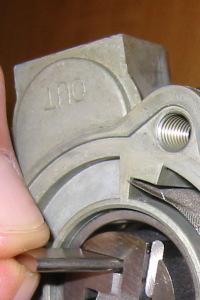
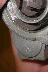
2 Advisory# SV Page 2 PROCEDURE TO CLEAN FUEL PUMP IMPELLER, VANES& SCREEN: *ATTENTION: READ THIS COMPLETE AND ENTIRE SERVICE ADVISORY FROM BEGINNING TO END AND UNDERSTAND EACH OF THE STEPS BEFORE PROCEEDING WITH FUEL PUMP SERVICING OR CALLING INDMAR WITH QUESTIONS. Removal of Fuel Pump from Engine: 1.Disconnect ALL electrical connections and fuel lines from fuel pump and remove fuel pump from engine before disassembly and cleaning of pump! Disassembly of Fuel Pump: 1.Removethe3boltsandlockwashersthatholdthetopcoverplateover the impeller assembly. These bolts are located below the rubber mounting grommetsatthetopofthefuelpump.


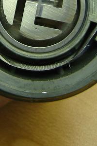
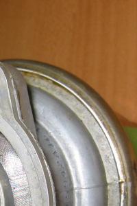
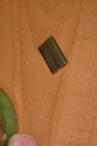
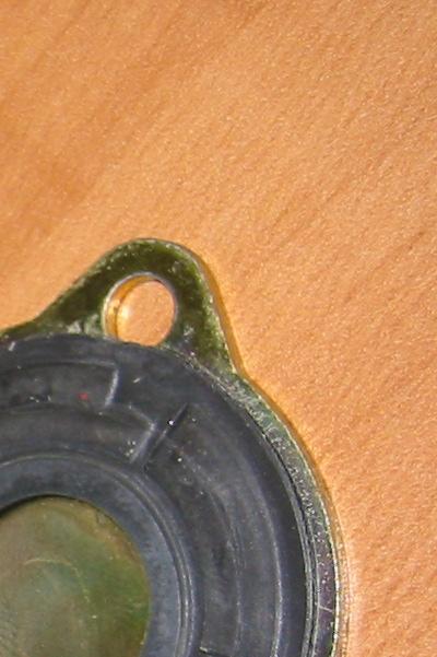
3 Advisory # SV Page 3 2.Remove the top cover plate, rubber seal and metal disc from atop the impeller assembly. 3.Remove impeller and 4 vanes from pump by inverting pump and tapping pump body gently. (NOTE: vanes and impeller should fall freely from pump body. Varnish and gums formed by gasoline breakdown may cause impeller and vanes to stick inside pump body. Tapping the pump body should free impeller and vanes to fall out.)


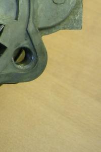
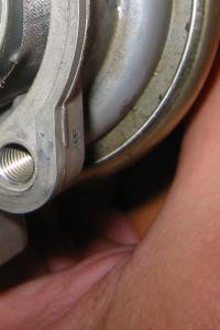
4 Advisory# SV Page 4 4.Remove screen filter inside pump body by gently lifting straight out or upwards. 5.Clean impeller body, 4 vanes, screen filter and inside of pump body chamber of all varnish, gum and trash with carburetor cleaner or other suitable cleaning solvent.


")


5 Advisory# SV Page 5 REASSEMBLY OF FUEL PUMP: 1. After cleaning, insert screen filter back into slot in fuel pump body. 2. Insert impeller body(center slot down) into pump body. 3.Insertthe4impellervanesintoimpellerbodyslotsandinsurethateach vane is free to move outward within their slots by centrifugal force.(note: both sides and edges of impeller vanes are interchangeable and can be reassembled with either edge out.)


6 Advisory#SV Page 6 4. Insert metal disc on top of impeller assembly. 5. Install top cover with rubber seal over impeller assembly and install 3 bolts and lock washers tight to seal. 6.Checkpumpoperationwith12voltDCsource. Pumpwillintakeairand pumpairouttheoutletifimpellervanesarecleanandfreetomoveintheir respective slots. 7. Reinstall fuel pump on engine. 8. Reconnect ALL fuel lines and electrical connections to fuel pump and check for leaks. 9. Add STA-BIL fuel stabilizer to engine gasoline supply and run engine to circulate fuel stabilizer throughout fuel system. This is a preventative maintenance step that will help avoid repeating this problem. This step is particularly important when winterizing the boat or when the engine will not beinuseforprolongedperiodsoftime! NOTE:This is a maintenance procedure and NOT A WARRANTY ISSUE. Varnish and gums produced by old gasoline breakdown are NOT DEFECTS IN MATERIALS OR WORKMANSHIP!
AEROMOTIVE Part # L 4V Fuel Rails INSTALLATION INSTRUCTIONS
 AEROMOTIVE Part # 14130 5.0L 4V Fuel Rails INSTALLATION INSTRUCTIONS CAUTION: Installation of this product requires detailed knowledge of automotive systems and repair procedures. We recommend that this
PLEASE READ ALL INSTRUCTIONS BEFORE INSTALLATION
 1 68 RFE VALVE BODY UPGRADE Part #: 1030360 Part #: 1030361 2007-11 (Early Model) 2010-12 (Late Model) PLEASE READ ALL INSTRUCTIONS BEFORE INSTALLATION 2 K I T C O N T E N T S : Please check to make sure
AEROMOTIVE Part # / L SOHC Ford Fuel Rail Kit INSTALLATION INSTRUCTIONS
 AEROMOTIVE Part # 14119 98 1/2-04 4.6L SOHC Ford Fuel Rail Kit INSTALLATION INSTRUCTIONS CAUTION: Installation of this product requires detailed knowledge of automotive systems and repair procedures. We
AEROMOTIVE Part # Ford 5.4L GT500 Shelby Mustang Fuel Rail Kit INSTALLATION INSTRUCTIONS
 AEROMOTIVE Part # 14145 07 Ford 5.4L GT500 Shelby Mustang Fuel Rail Kit INSTALLATION INSTRUCTIONS CAUTION: Installation of this product requires detailed knowledge of automotive systems and repair procedures.
AEROMOTIVE Part # C5 Corvette Fuel Rail Kit INSTALLATION INSTRUCTIONS
 AEROMOTIVE Part # 14128 99-04 C5 Corvette Fuel Rail Kit INSTALLATION INSTRUCTIONS CAUTION: Installation of this product requires detailed knowledge of automotive systems and repair procedures. We recommend
LEAK TEST PROCEDURE MRT4-DC LIFTERS SINGLE VACUUM SYSTEMS TESTING AND MAINTENANCE MUST BE DONE BY A QUALIFIED PERSON KEEP FOR FUTURE REFERENCE
 LEAK TEST PROCEDURE MRT4-DC LIFTERS SINGLE VACUUM SYSTEMS TESTING AND MAINTENANCE MUST BE DONE BY A QUALIFIED PERSON KEEP FOR FUTURE REFERENCE TST-011 Rev. 2013-049 Page 1 of 12 THIS PAGE INTENTIONALLY
AEROMOTIVE Part # /2 4.6L SOHC Ford Fuel Rail Kit INSTALLATION INSTRUCTIONS
 AEROMOTIVE Part # 14125 96-98 1/2 4.6L SOHC Ford Fuel Rail Kit INSTALLATION INSTRUCTIONS CAUTION: Installation of this product requires detailed knowledge of automotive systems and repair procedures. We
AEROMOTIVE Part # GM LS1 Fuel Rails INSTALLATION INSTRUCTIONS
 AEROMOTIVE Part # 14106 GM LS1 Fuel Rails INSTALLATION INSTRUCTIONS CAUTION: Installation of this product requires detailed knowledge of automotive systems and repair procedures. We recommend that this
LEAK TEST PROCEDURE MRTALPCH611LDC REMOTE READY LIFTERS W/ 3 BUTTON CONTROL APPLICABLE TO LIFTERS WITH SERIAL NUMBERS GREATER THAN #
 LEAK TEST PROCEDURE MRTALPCH611LDC REMOTE READY LIFTERS W/ 3 BUTTON CONTROL APPLICABLE TO LIFTERS WITH SERIAL NUMBERS GREATER THAN # 20100742 TESTING AND MAINTENANCE MUST BE DONE BY A QUALIFIED PERSON
AEROMOTIVE Part # Ford 5.4L Shelby GT500 Mustang INSTALLATION INSTRUCTIONS
 AEROMOTIVE Part # 14144 07 Ford 5.4L Shelby GT500 Mustang INSTALLATION INSTRUCTIONS CAUTION: Installation of this product requires detailed knowledge of automotive systems and repair procedures. We recommend
PERFORMANCE GPM of Water At Total Head in Feet
 Please read and save this Repair Parts Manual. Read this manual and the General Operating Instructions carefully before attempting to assemble, install, operate or maintain the product described. Protect
EXHAUST GAS RECIRCULATION (EGR) SYSTEM (4A FE)
 SYSTEM (4A FE)") ENGINE EG121 EXHAUST GAS RECIRCULATION (EGR) SYSTEM (4AFE) EGR SYSTEM INSPECTION 1. INSPECT AND CLEAN FILTER IN EGR VACUUM MODULATOR (a) Remove the cap and filter. (b) Check the filter for contamination
ENGINE EG121 EXHAUST GAS RECIRCULATION (EGR) SYSTEM (4AFE) EGR SYSTEM INSPECTION 1. INSPECT AND CLEAN FILTER IN EGR VACUUM MODULATOR (a) Remove the cap and filter. (b) Check the filter for contamination
AEROMOTIVE Volkswagen 1.8T Fuel Rail Part # INSTALLATION INSTRUCTIONS
 AEROMOTIVE Volkswagen 1.8T Fuel Rail Part # 14163 INSTALLATION INSTRUCTIONS CAUTION: Installation of this product requires detailed knowledge of automotive systems and repair procedures. We recommend that
AEROMOTIVE Part # L Ford F L Ford Expedition L Ford F-250 Super Duty INSTALLATION INSTRUCTIONS
 AEROMOTIVE Part # 14118 97-03 5.4L Ford F-150 97-02 5.4L Ford Expedition 98-03 5.4L Ford F-250 Super Duty INSTALLATION INSTRUCTIONS CAUTION: Installation of this product requires detailed knowledge of
Winterizing Supplies & Procedure 1999 Maristar 210 VRS, LTR 330 hp, EFI, MPI
 Winterizing Supplies & Procedure 1999 Maristar 210 VRS, LTR 330 hp, EFI, MPI SUPPLIES/PARTS/TOOLS Supplies: Sta-Bil Fuel stabilizer (1 oz/2.5 gals); 45 gal tank = 18 oz. +/- 6 qts. engine oil (Pennzoil
1-1/2 Inch Self-Priming Centrifugal Pumps Refer to pump manual for General Operating and Safety Instructions.
 Please read and save this Repair Parts Manual. Read this manual and the General Operating Instructions carefully before attempting to assemble, install, operate or maintain the product described. Protect
AEROMOTIVE Part # C5 Corvette Fuel Rail / Regulator Kit INSTALLATION INSTRUCTIONS
 AEROMOTIVE Part # 14129 99-04 C5 Corvette Fuel Rail / Regulator Kit INSTALLATION INSTRUCTIONS CAUTION: Installation of this product requires detailed knowledge of automotive systems and repair procedures.
CARBURETOR. Preliminary Check. Removal of DuraForce Carburetor
 Fuel Leaks From Carburetor (Leaking starts after running, stops after shutdown) Note: This condition which does NOT drain the fuel tank is called spit-back. Possible Causes Engine RPM out of proper range
EZ-IN Series Turbine Flowmeter
 Class I, Group A, B, C, D, Division I Complies with ASME Standard B31.3 NUFLO EZ-IN Series Turbine Flowmeter Installation Manual Part No. 9A-100062997, Rev. 01 Measurement Systems EZ-IN Series BF Turbine
PLEASE READ ALL INSTRUCTIONS BEFORE INSTALLATION
 1 68 RFE VALVE BODY UPGRADE Part #: 1030360 Part #: 1030361 2007-11 (Early Model) 2010-12 (Late Model) PLEASE READ ALL INSTRUCTIONS BEFORE INSTALLATION AFTERMARKET TUNERS OR TCMS There is a number of aftermarket
Maintenance Information
 45528270 Edition 1 June 2007 Barring Motor T480 Series Maintenance Information Save These Instructions WARNING Always wear eye protection when operating or performing maintenance on this Barring Motor.
Maintenance Information
 Form 04584058 Edition 1 November 2004 Air Impactool 2141P and 2141PSP Maintenance Information Save These Instructions Disassembly General Instructions 1. Do not disassemble the tool any further than necessary
IMPORTANT SAFETY INSTRUCTIONS
 OWNER S MANUAL FLO-MASTER XP2 SERIES PUMPS IMPORTANT SAFETY INSTRUCTIONS When installing and using this electrical equipment, basic safety precautions should always be followed, including the following:
AEROMOTIVE Part # L Ford F L Ford Expedition L Ford F-250 Super Duty INSTALLATION INSTRUCTIONS
 AEROMOTIVE Part # 14118 97-03 5.4L Ford F-150 97-02 5.4L Ford Expedition 98-03 5.4L Ford F-250 Super Duty INSTALLATION INSTRUCTIONS CAUTION: Installation of this product requires detailed knowledge of
AEROMOTIVE Part # INSTALLATION INSTRUCTIONS
 AEROMOTIVE Part # 14102 INSTALLATION INSTRUCTIONS CAUTION: Installation of this product requires detailed knowledge of automotive systems and repair procedures. We recommend that this installation be carried
ENERGY SMART TROUBLESHOOTING
 ENERGY SMART TROUBLESHOOTING Symptom No power to the unit. Possible Solution Verify the unit is plugged into a 20 Amp, GFCI circuit and the Power Switch is set to the ON position. Is the GFCI circuit breaker
Tillotson Tc3A Carburator
 Tillotson Tc3A Carburator 176 FUEL SYSTEMS - 5B-11 CENTER BOWL TYPE CARBURETOR Removal 1. Remove front cowl cover and wrap-around cowl. 2. Remove swivel link from lower carburetor. (Figure 2) 3. Loosen
CR, CRN, CRNG 2 4 Dismantling & Reassembly
 GRUNFOS R SERVIE MNUL R, RN, RNG 2 ismantling & Reassembly ONTENTS ismantling Procedures... Page 2 When Should Part e Replaced?...Page 5 Reassembly Procedures... Page 6 Setting The oupling Height... Page
AMERICAN AVK COMPANY AVK SERIES 24 - HIGH PRESSURE, WET BARREL HYDRANT FIELD MAINTENANCE AND INSTRUCTION MANUAL TABLE OF CONTENTS
 AMERICAN AVK COMPANY AVK SERIES 24 - HIGH PRESSURE, WET BARREL HYDRANT FIELD MAINTENANCE AND INSTRUCTION MANUAL TABLE OF CONTENTS EXPLODED ASSEMBLY / PARTS LIST INTRODUCTION / DESCRIPTION RECEIVING AND
DEMON CARBURETOR MANUAL CHOKE KIT #421441
 DEMON CARBURETOR MANUAL CHOKE KIT #421441 CHOKE INSTALLATION INSTRUCTIONS LIT703 This manual choke kit is designed to be used on any Demon Carburetor with a choke tower. This covers the Road Demon Jr.
REMOVAL & INSTALLATION
 REMOVAL & INSTALLATION NOTE: For reassembly reference, label all electrical connectors, vacuum hoses and fuel lines before removal. Also place mating marks on engine hood and other major assemblies before
SLM - Sealing Liquid Monitor INSTRUCTIONS FOR USE
 INSTRUCTIONS FOR USE 1/8 1 INSTALLATION SLM - Sealing Liquid Monitor INSTRUCTIONS FOR USE 1.1 Mounting The SLM has a mounting plate for simple installation. The SML can be mounted using a bolt already
LEAK TEST PROCEDURE DC CHANNEL LIFTERS SINGLE VACUUM SYSTEMS TESTING AND MAINTENANCE MUST BE DONE BY A QUALIFIED PERSON KEEP FOR FUTURE REFERENCE
 LEAK TEST PROCEDURE DC CHANNEL LIFTERS SINGLE VACUUM SYSTEMS TESTING AND MAINTENANCE MUST BE DONE BY A QUALIFIED PERSON KEEP FOR FUTURE REFERENCE TST-008 Rev. 2013-048 Page 1 of 10 THIS PAGE INTENTIONALLY
Rebuild and Adjustment Manual for Models 2010, 2300, 4010, 4011, 4150, 4160, 4165, 4175, and 4500
 Rebuild and Adjustment Manual for Models 2010, 2300, 4010, 4011, 4150, 4160, 4165, 4175, and 4500 WARNING! These instructions must be read and fully understood before beginning installation. Failure to
Maintenance Information
 16573370 Edition 2 February 2014 Air Grinder 99V Series Maintenance Information Save These Instructions Product Safety Information WARNING Failure to observe the following warnings, and to avoid these
07ES05C, 1ES07C, 1ES10C, 12ES15C, 15ES20C, 2ES30C Series
 Please read and save this Repair Parts Manual. Read this manual and the General Operating Instructions carefully before attempting to assemble, install, operate or maintain the product described. Protect
Carriage Height Calibration
 979-530-0207 Carriage Height Calibration The purpose of this Service Calibration is to adjust the distance between the Carriage Assembly and the Center Platen. This calibration is necessary in order to
AEROMOTIVE Part # Subaru Fuel Rails for Top Feed Injectors WRX & STI INSTALLATION INSTRUCTIONS
 AEROMOTIVE Part # 14135 Subaru Fuel Rails for Top Feed Injectors 02-14 WRX & 07-14 STI INSTALLATION INSTRUCTIONS CAUTION: Installation of this product requires detailed knowledge of automotive systems
CARBURETOR - HITACHI 2-BBL
 CARBURETOR - HITACHI 2-BBL 1986 Isuzu Trooper II 1986 Hitachi Carburetors HITACHI DCH340, DCR384, DFP340, DFP384 & DHP340 2-BARREL P UP & Trooper II DESCRIPTION Carburetor is a 2-barrel downdraft type
STEERING SYSTEM 6 A POWER STEERING
 STEERING SYSTEM 6 A 22147 POWER STEERING Table of Contents Page Specifications............................ 6A-1 Torque Specification................... 6A-1 Special Tools............................ 6A-1
POWER-FLOW:An air intake evolution. Tools required: Part number PF Toyota FJ 4.0L V6
 Part number PF2057 2006 Toyota FJ 4.0L V6 1- MR Tech Power-flow Intake system 1-8 Inverted top power filter (#1022) 1- Power Box-contents: PB400P-8 1- Powerbox skin plate (A) (#6043) 1- Stabilizer top
GBP784B INSTALLATION TOOL
 GBP784B INSTALLATION TOOL GAGE BILT MADE IN U.S.A. GAGE BILT PRODUCTS CORP. 14500 Barber Drive (586) 771-7664 Warren, Mi 48088 (586) 771-2665 Fax e-mail:solutions@gagebilt.com / www.gagebilt.com TABLE
THANK YOU FOR CHOOSING KÜRYAKYN! -cont.-
 I N S TA L L AT I O N H Y P E R C H A R G E R A I R C L E A N E R 9 4 1 0 FITS: KAWASAKI 95-UP VN800 VULCAN PART # INCLUDED 600163 1 Hypercharger Chrome with drilled back 8513 1 K&N Filter Element 8593
AEROMOTIVE Part # Ford 5.0 Liter INSTALLATION INSTRUCTIONS
 AEROMOTIVE Part # 14101 86-98 Ford 5.0 Liter INSTALLATION INSTRUCTIONS CAUTION: Installation of this product requires detailed knowledge of automotive systems and repair procedures. We recommend that this
AEROMOTIVE Part # Subaru STI Fuel Rail Kit INSTALLATION INSTRUCTIONS
 AEROMOTIVE Part # 14137 04-06 Subaru STI Fuel Rail Kit INSTALLATION INSTRUCTIONS CAUTION: Installation of this product requires detailed knowledge of automotive systems and repair procedures. We recommend
AVK SAUDI VALVES MANUFACTURING COMPANY
 AVK SAUDI VALVES MANUFACTURING COMPANY AVK SERIES 24 - HIGH PRESSURE, WET BARREL HYDRANT FIELD MAINTENANCE AND INSTRUCTION MANUAL TABLE OF CONTENTS EXPLODED ASSEMBLY / PARTS LIST INTRODUCTION / DESCRIPTION
OWNER S MANUAL EVOLUTION 3500, 4500, 5500, & 8500 SERIES PUMPS
 OWNER S MANUAL EVOLUTION 3500, 4500, 5500, & 8500 SERIES PUMPS IMPORTANT SAFETY INSTRUCTIONS When installing and using this electrical equipment, basic safety precautions should always be followed, including
FOR FUTURE REFERENCE SERIES 93HPS
 Hypro Series 93HPS Hydraulically Driven Wetseal Multistage Pumps Repair Manual KEEP FOR FUTURE REFERENCE Form L-1578R Rev. A SERIES 93HPS Hydraulically Driven Stainless Steel Multistage Centrifugal Pumps
TABLE OF CONTENTS. 3 Outlet Stainless Steel Body. 3 Outlet Ductile Body. 2 Outlet Ductile Body 2 Outlet Bronze Body
 AVK SERIES 24 - HIGH PRESSURE, WET BARREL HYDRANT FIELD MAINTENANCE AND INSTRUCTION MANUAL TABLE OF CONTENTS EXPLODED ASSEMBLY / PARTS LIST INTRODUCTION / DESCRIPTION RECEIVING AND STORAGE INSTALLATION
Disassembly and Reassembly for CBB (Double Acting) Series Pneumatic Actuators
 Series Pneumatic Actuators") MECATORK S.A.S Release: May 2012 Disassembly and Reassembly for CBB (Double Acting) Series Pneumatic Actuators MECATORK S.A.S Table of Contents May 2012 Table of Contents Section 1: Introduction 1.1 General
MECATORK S.A.S Release: May 2012 Disassembly and Reassembly for CBB (Double Acting) Series Pneumatic Actuators MECATORK S.A.S Table of Contents May 2012 Table of Contents Section 1: Introduction 1.1 General
TPH Series. MULTISTAGE CENTRIFUGAL PUMP Instruction Manual WALRUS PUMP CO., LTD. ISO 9001 Certified NSF/ANSI 372
 TPH Series MULTISTAGE CENTRIFUGAL PUMP Instruction Manual NSF/ANSI 372 ISO 9001 Certified WALRUS PUMP CO., LTD. EC Declaration of Conformity Manufacturer: Walrus Pump Co., Ltd. Address: No.8314, Dapiantou,
TIMING CHAIN COMPONENTS
 h Page 1 of 52 TIMING CHAIN COMPONENTS ht Page 2 of 52 Fig. 24: Displaying Timing Chain Components (1 Of 2) Page 3 of 52 Fig. 25: Displaying Timing Chain Components (2 Of 2) Page 4 of 52 REMOVAL NOTE:
Service Manual Air Tech Second Stage
 Service Manual Air Tech Second Stage Copyright 2002, Cressi-sub Revised 3/2002 2 Air Tech Second Stage Service Manual Contents BEFORE STARTING... 3 DISASSEMBLY... 3 PARTS CLEANING AND LUBRICATION... 9
WARNING Carefully Read These Instructions Before Use
 DO NOT RETURN THIS SPRAYER TO STORE Call: 1-800-950-4458 Backpack Sprayer Use and Care Manual Manufactured for Northern Tool + Equipment Co., Inc. WARNING Carefully Read These Instructions Before Use Model
Self-Priming Centrifugal Pumps Refer to pump manual for General Operating and Safety Instructions.
 Please read and save this Repair Parts Manual. Read this manual and the General Operating Instructions carefully before attempting to assemble, install, operate or maintain the product described. Protect
TPH Series. MULTISTAGE CENTRIFUGAL PUMP Instruction Manual. Walrus America Inc. ISO 9001 Certified
 TPH Series MULTISTGE CENTRIFUGL PUMP Instruction Manual ISO 9001 Certified Walrus merica Inc 234867 EC Declaration of Conformity Manufacturer: Walrus Pump Co., Ltd. ddress: No. 83-14, Dapiantou, Sanjhih
DIESEL FUEL Click on the applicable bookmark to selected the required model year
 DIESEL FUEL 13E-2 DIESEL FUEL General Information/Service Specifications/ Special Tool/On-vehicle Service GENERAL INFORMATION 13300010025 The fuel is drawn out of the fuel tank by means of the feed pump
I N S TA L L AT I O N
 I N S TA L L AT I O N k i t 9 9 5 4 Fits: all honda 750 shadow aero models Part # Included 509944 1 Skull head cover 1 Cage assembly 1 Backing plate, 3-point base 1 Dual velocity ring (not used) 1 Mounting
INSTALLATION INSTRUCTIONS
 THANK YOU FOR CHOOSING KURYAKYN! Protect yourself and others from possible injury and property damage or loss. Pay close attention to all instructions, warnings, cautions, and notices regarding the installation,
Operation and Maintenance Manual
 BM / BMA Hydrometers ½ Operation and Maintenance Manual i This manual is intended for use by the users of this equipment. The information contained herein is the property of the Arad Ltd. Dalia and may
Disassembly and Reassembly for CBB-SR (Spring Return) Series Pneumatic Actuators
 Series Pneumatic Actuators") Part Number: VA001-196-31, Rev. 0 Release: May 2012 Disassembly and Reassembly for CBB-SR (Spring Return) Series Pneumatic Actuators Table of Contents Part Number: VA001-196-31, Rev. 0 May 2012 Table of
Part Number: VA001-196-31, Rev. 0 Release: May 2012 Disassembly and Reassembly for CBB-SR (Spring Return) Series Pneumatic Actuators Table of Contents Part Number: VA001-196-31, Rev. 0 May 2012 Table of
NOTE: Visit our website at for video repair procedures, under the Tools section.
 Repair Instructions Hypro Repair Tools: Tool Box No. 3010-0168 1/4" Allen Wrench No. 3020-0008 Support Bars (2) No. 3010-0064 Port Brush No. 3010-0066 1/16" Allen Wrench No. 3020-0009 Brush Holder No.
Thompson Performance, LLC - POWERBLAST PLATE
 Thompson Performance, LLC - POWERBLAST PLATE INSTALLATION INSTRUCTIONS FOR PBP EC-56 AND PBP EC-78 IMPORTANT NOTE: Proper installation and safe use of the POWERBLAST PLATE is the responsibility of the
PNEUMATIC SLIDING VALVE
 INSTALLATION, OPERATION, & #: MM-SV001 6-23-09 Rev. A Page 1 of 8 PNEUMATIC SLIDING VALVE PART NUMBERS (Including, but not inclusive) SV704MSTS, SV714MSTS, SV754MSTS, SV764MSTS, SV774MSTS, SV706MSTS, SV716MSTS,
DESCRIPTION Acura TSX SUSPENSION Front - TSX. NOTE: For system description and component location, see Fig. 1.
 2004 SUSPENSION Front - TSX DESCRIPTION NOTE: For system description and component location, see Fig. 1. Fig. 1: Identifying Front Suspension Components Wednesday, March 12, 2008 8:30:45 8:30:55 PM Page
Forge Motorsport BMW N54 Diverter Valves
 Forge Motorsport BMW N54 Diverter Valves Please thoroughly read through and familiarize yourself with these instructions in their entirety prior to beginning any part of the installation process of any
INSTALLATION & SERVICE INSTRUCTION MANUAL W.A. KATES FLOW CONTROLLERS FC VALVE MODELS E THRU M
 INSTALLATION & SERVICE INSTRUCTION MANUAL W.A. KATES FLOW CONTROLLERS FC VALVE MODELS E THRU M IMPORTANT 1. W. A. Kates flow rate controllers are designed to accurately regulate flows and are precision
INSTALLATION. Note: Not all of the included parts will be used during this installation. -cont.-
 Driving Lights for Road Glide 5007 Fits: 98-up Road Glide PartS Included 1 Right Light Assembly 1 Left Light Assembly 1 Right Mounting Bracket 1 Left Mounting Bracket 1 Hardware Kit Including: 2 Narrow
AEROMOTIVE Part # Subaru Fuel Rails for Top Feed Injectors WRX & STI INSTALLATION INSTRUCTIONS
 AEROMOTIVE Part # 14134 Subaru Fuel Rails for Top Feed Injectors 02-14 WRX & 07-14 STI INSTALLATION INSTRUCTIONS CAUTION: Installation of this product requires detailed knowledge of automotive systems
A-PDF Split DEMO : Purchase from to remove the watermark
 5-18 FUEL AND LUBRICATION SYSTEM A-PDF Split DEMO : Purchase from www.a-pdf.com to remove the watermark Use a % size drill bit with a drill-stop to remove the pilot screw plug. Set the drill-stop 6 mm
Firehawk Responder Second Stage Regulator
 Firehawk Responder Second Stage Regulator MAINTENANCE AND REPAIR MSA 511 (L) Rev. 4 MSA 2015 Prnt. Spec. 10000005389(I) Mat. 10096394 Doc. 10096394 Replacement Kits and Overhaul Kit P/N Description Firehawk
GEN-3 Super-duty Supercharger Shaft Kit PART# - RY17040-UK-6S5-3
 GEN-3 Super-duty Supercharger Shaft Kit PART# - RY17040-UK-6S5-3 We strongly recommend the use of a service manual to familiarize yourself with the various components and procedures involved with this
7. FUEL SYSTEM ('04 - '05)
") 7. FUEL SYSTEM ('04 - '05) SYSTEM COMPONENTS 7-2 CARBURETOR DISASSEMBLY 7-81 SERVICE INFORMATION 7-3 CARBURETOR ASSEMBLY 7-14 TROUBLESHOOTING 7-4 CARBURETOR INSTALLATION 7-21 AIR CLEANER HOUSING 7-5 PILOT
7. FUEL SYSTEM ('04 - '05) SYSTEM COMPONENTS 7-2 CARBURETOR DISASSEMBLY 7-81 SERVICE INFORMATION 7-3 CARBURETOR ASSEMBLY 7-14 TROUBLESHOOTING 7-4 CARBURETOR INSTALLATION 7-21 AIR CLEANER HOUSING 7-5 PILOT
INSTALLATION & OPERATING INSTRUCTIONS
 INSTALLATION & OPERATING INSTRUCTIONS WARNING RISK OF ELECTRIC SHOCK. CONNECT ONLY TO A CIRCUIT PROTECTED BY A GROUND-FAULT CIRCUIT-INTERRUPTER. THE UNIT SHOULD BE INSTALLED BY A QUALIFIED SERVICE REPRESENTATIVE.
Acura NSX Harness Bar Parts List and Installation Instructions
 Acura NSX Harness Bar Parts List and Installation Instructions DISCLAIMER Harness bars are not intended for roll over protection. This harness bar is intended to facilitate the installation of four-, five-
PRODUCT OBSOLETED 1Q16
 TECHNICAL SERVICE MANUAL HEAVY DUTY STEEL EXTERNAL MOUNTED PUMPS SERIES 123 AND 4123 SIZES H-LL SECTION TSM 151.1 PAGE 1 OF 13 ISSUE C CONTENTS Introduction 1 Special Information 2 Maintenance 3 Packed
Specifications Information and Repair Parts Manual , , , &
 Please read and save this Repair Parts Manual. Read this manual and the General Operating Instructions carefully before attempting to assemble, install, operate or maintain the product described. Protect
Oreck Magnesium Series Service Manual. The Oreck Manufacturing Company
 Oreck Magnesium Series Service Manual The Oreck Manufacturing Company 08/2012 10/2011 The Oreck Manufacturing Company Contents Covering all Magnesium Upright Models Including: LW100, LW125, LW1000, AND
DL/DS Series Diaphragm Valve
 DL/DS Series Diaphragm Valve Service Instructions DL Series (Lever Handle) Valve DS Series (Round Handle) Valve Valves are shown with tube butt weld ends. These instructions also apply to DL or DS series
AEROMOTIVE Part # Subaru STI Fuel Rails INSTALLATION INSTRUCTIONS
 AEROMOTIVE Part # 14136 04-06 Subaru STI Fuel Rails INSTALLATION INSTRUCTIONS CAUTION: Installation of this product requires detailed knowledge of automotive systems and repair procedures. We recommend
3" & 4" Cast Iron Self-Priming Centrifugal Pump Instruction Manual
 12 3" & 4" Cast Iron Self-Priming Centrifugal Pump Instruction Manual 333 & 444 Series Read these instructions and the instructions covering operation of the pump drive unit. Do not operate the gas engine
PRO-R AIR CLEANER FOR KAWASAKI 9462
 I N S TA L L AT I O N PRO-R AIR CLEANER FOR KAWASAKI 9462 FITS: 95-04 VN1500 (SINGLE CARB MODELS) PART # INCLUDED 500205 1 Pro R Hypercharger Chrome Assembly Including: 1 Dual Velocity Ring (in plastic
Super T QR20 INSTRUCTIONS GENERAL RULES
 INSTRUCTIONS GENERAL RULES 1. Where specified, assemble and disassemble the shock absorption system using the MARZOCCHI special tools only. 2. On reassembling the suspension system, always use new seals.
INSTALLATION INSTRUCTIONS South Highway 11 Westminster, SC Toll Free (888) (864) FAX (864)
 (864) FAX (864)") These instructions apply to the servicing of the Lift Technologies MaxiMizer Integral Sideshifters Cylinder Head. WARNING! Unless the steps in the following Installation Instructions are properly followed
These instructions apply to the servicing of the Lift Technologies MaxiMizer Integral Sideshifters Cylinder Head. WARNING! Unless the steps in the following Installation Instructions are properly followed
Artisan Technology Group is your source for quality new and certified-used/pre-owned equipment
 Artisan Technology Group is your source for quality new and certified-used/pre-owned equipment FAST SHIPPING AND DELIVERY TENS OF THOUSANDS OF IN-STOCK ITEMS EQUIPMENT DEMOS HUNDREDS OF MANUFACTURERS SUPPORTED
BETTIS SERVICE INSTRUCTIONS DISASSEMBLY AND REASSEMBLY FOR CB-SR-S SEISMIC SPRING RETURN SERIES PNEUMATIC ACTUATORS
 BETTIS SERVICE INSTRUCTIONS DISASSEMBLY AND REASSEMBLY FOR CB-SR-S SEISMIC SPRING RETURN SERIES PNEUMATIC ACTUATORS PART NUMBER: 102264 REVISION: "C" DATE: November 2000 Page 1 of 11 1.0 INTRODUCTION 1.1
3 Scotch-Weld. User s Manual. Polyurethane Reactive (PUR) Easy Adhesive Applicator
 Easy Adhesive Applicator") 3 Scotch-Weld Polyurethane Reactive (PUR) Easy Adhesive Applicator 120V. USA 100V. JAPAN 120V. USA REFURB User s Manual Use only with 3M Scotch-Weld Polyurethane Reactive (PUR) Easy Adhesives Please read
3 Scotch-Weld Polyurethane Reactive (PUR) Easy Adhesive Applicator 120V. USA 100V. JAPAN 120V. USA REFURB User s Manual Use only with 3M Scotch-Weld Polyurethane Reactive (PUR) Easy Adhesives Please read
TOYOTA COROLLA ILLUMINATED DOOR SILLS Preparation
 Preparation Part Number: PT942-02140 Kit Contents Item # Quantity Reqd. Description 1 1 Illuminated Scuff plate, Front Right Hand 2 1 Illuminated Scuff plate, Front Left Hand 3 1 Door Scuff plate, Rear
LEXUS GS 350/450h ILLUMINATED DOOR SILLS Preparation
 Preparation Part Number: PT922-30120 (GS350) PT922-30130 (GS450h) NOTE: Part number of this accessory may not be the same as the part number shown. Kit Contents Item # Quantity Req'd. Description 1 1 Illuminated
Fluid-O-Tech ROTOFLOW ROTARY VANE PUMP REBUILD MANUAL
 Fluid-O-Tech PUMP TECHNOLOGY AT ITS BEST WWW.FLUID-O-TECH.COM Office: 161 Atwater St., Plantsville, CT 06479 Phone: (860) 276-9270 Fax: (860) 620-0193 ROTOFLOW ROTARY VANE PUMP REBUILD MANUAL 08/09 Ed.,
TOYOTA im INTERIOR LIGHT KIT Preparation
 Preparation Part Number: PT922-12170 Kit Contents Item # Quantity Reqd. Description 1 1 Main Wire Harness 2 1 Switch 3 1 Switch Header 4 1 ECU 5 1 ECU Bracket 6 1 Hardware Kit 7 1 Instruction Card 8 1
Series: PFUEG 1/12HP, 5000 RPM, 60 Hz Utility Pumps
 INSTALLATION MANUAL Series: 1/12HP, 5000 RPM, 60 Hz ISP No: - 6/09 General Safety Information Before installation, read the following instructions carefully. Failure to follow instruction and Safety information
INTAKE AIR TEMPERATURE SENSOR (IAT)
") INTAKE AIR TEMPERATURE SENSOR (IAT) 4.8 Refer to the ELECTRICAL DIAGNOSTIC MANUAL for information on the function and testing of the intake air temperature sensor (IAT sensor). sm054 To prevent accidental
INTAKE AIR TEMPERATURE SENSOR (IAT) 4.8 Refer to the ELECTRICAL DIAGNOSTIC MANUAL for information on the function and testing of the intake air temperature sensor (IAT sensor). sm054 To prevent accidental
SPL HICAS ELIMINATOR KIT
 SPL HICAS ELIMINATOR KIT Steps to installing the Hicas eliminator kit: 1. Unbolt and remove Hicas actuator. 2. Remove Hicas ball joint and install toe bushing 3. Install Hicas eliminator bracket and toe
TABLE OF CONTENTS I. SERVICE & MAINTENANCE PROCEDURES. 1) Opening and closing of door latch. 2) Latch assembly and adjustment
 Opening and closing of door latch. 2) Latch assembly and adjustment") TABLE OF CONTENTS I. SERVICE & MAINTENANCE PROCEDURES 1) Opening and closing of door latch 2) Latch assembly and adjustment 3) Latch cover removal and replacement 4) Upper slider track adjustment 5) Lower
TABLE OF CONTENTS I. SERVICE & MAINTENANCE PROCEDURES 1) Opening and closing of door latch 2) Latch assembly and adjustment 3) Latch cover removal and replacement 4) Upper slider track adjustment 5) Lower
"F" SERIES (Cont.) F100 SERIES GOVERNOR GOVERNOR ASSEMBLY AND OPERATION (EARLY MODELS BEFORE ) (HEX SHAPED, GOVERNOR COLLAR)
 F100 SERIES GOVERNOR GOVERNOR ASSEMBLY AND OPERATION (EARLY MODELS BEFORE ) (HEX SHAPED, GOVERNOR COLLAR)") "F" SERIES (Cont.) GOVERNOR ASSEMBLY AND OPERATION (EARLY MODELS BEFORE 1 98 1 ) (HEX SHAPED, GOVERNOR COLLAR) The governor air vane assembly is an in- As mowing conditions change the governor tegral component
"F" SERIES (Cont.) GOVERNOR ASSEMBLY AND OPERATION (EARLY MODELS BEFORE 1 98 1 ) (HEX SHAPED, GOVERNOR COLLAR) The governor air vane assembly is an in- As mowing conditions change the governor tegral component
Approximate installation time: 2 hrs. REV. DATE: 3/17/2016 Page 1 of 7
 Installation Instructions BR20 Rear Bumper Replacement Part Number 28169T 2011-2014 Chevrolet Silverado 2500HD & 3500HD 2/4WD Do not attempt to install this product on any vehicle other than the one listed
REPAIR INSTRUCTION - MP4120-SWS/MP4124-SWS
 Disassembly sequence REPAIR INSTRUCTION - MP4120-SWS/MP4124-SWS 1. With a 27mm wrench, remove the three discharge plugs (#48) and three inlet plugs (#42A) from the manifold (#43). 2. Inspect the plug o-rings
DRIVE AXLE Volvo 960 DESCRIPTION & OPERATION AXLE IDENTIFICATION DRIVE AXLES Volvo Differentials & Axle Shafts
 DRIVE AXLE 1994 Volvo 960 1994 DRIVE AXLES Volvo Differentials & Axle Shafts 960 DESCRIPTION & OPERATION All 960 station wagon models use type 1041 rear axle assembly. All 960 4-door models use type 1045
Tactical Laser Illuminator
 M6 Operator s Manual Operator s Manual Tactical Laser Illuminator MADE IN THE USA Table of Contents Section Page Warnings and Cautions... 1 Safety Summary... 4 M6 TLI (Tactical Laser Illuminator) Parts