Instruction Manual & Safety Warnings
|
|
|
- Peter Washington
- 6 years ago
- Views:
Transcription
1 Table of Contents Instruction Manual & Safety Warnings Important Safety Warnings and Instructions Electrical precautions 1 Battery preparation 1 Battery precautions 1 Introduction Items included in system 2 Additional items needed 2 Replacement parts list 2 System specifications 2 Pump & Pipe Installation Instructions Installation options 3 Direct discharge to outside 4 Connection to existing discharge 5 Direct discharge for narrow sumps6 Connection to existing discharge for narrow sumps 7 Battery Instructions 8,9 Control Unit Connections Mounting the control unit 9 Positioning the float switch 9 Connecting the pump 10 Installing the battery fluid sensor10 Connecting the battery 10 Connecting the charger 10 Understanding the Warning Lights and Alarms Silencing the alarm during


2 an emergency 11 Power alarm 11 Water alarm 11 Pump alarm 12 Replacing the pump 12 System 13 Battery alarm 13 Cleaning battery terminals 13 Replacing the battery 14 Testing the System Testing the pump 15 Testing the float switch 15 Parts & Service Information Technical support 15 Troubleshooting Guide 16 Warranty 17 Other Products 18 age 1 I M P O R T A N T : E v e n i f y o Backup Sump Pump
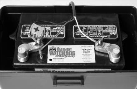
3 Important Safety Warnings & Instructions SAVE THESE INSTRUCTIONS. This manual contains important SAFETY WARNINGS and OPERATING INSTRUCTIONS for the Basement Watchdog Emergency battery backup sump pump system. You will need to refer to it before attempting any installation or maintenance. ALWAYS keep these instructions with the unit so that they will be easily accessible. Failure to read and follow these warnings and instructions could result in property damage, serious injury, or death. It is important to read this manual, even if you did not install the Basement Watchdog backup sump pump system, since this manual contains safety information regarding the use and maintenance of this product. DO NOT DISCARD THIS MANUAL. ELECTRICAL PRECAUTIONS! DANGER Risk of electrical and fire hazard. May result in death, serious injury, shock or burns. To help reduce these risks, observe the following precautions: DO NOT walk on wet areas of the basement until all power has been turned off. If the main power supply is in a wet basement, call an electrician. NEVER handle the control unit with wet hands or while standing on a wet surface. ALWAYS unplug the control unit and disconnect the cables from the battery u h a before attempting any maintenance or cleaning. ALWAYS unplug the main pump when installing or servicing the backup pump or float switch to avoid electric shock. DO NOT expose the control unit to rain or snow. DO NOT pull the cord when disconnecting the control unit. Pull the plug. DO NOT use an extension cord unless absolutely necessary. If an extension cord must be used, be sure the plug has the same configuration as the plug on the control unit. DO NOT use an attachment not recommended or sold by the manufacturer. It may result in a risk of fire or injury from an electrical shock. DO NOT operate the control unit if it has received a sharp blow, been dropped, or otherwise damaged in any way. DO NOT use pump in pits handling raw sewage, salt water, or hazardous liquids. DO NOT disassemble the control unit. When service is required, contact Glentronics technical support at , option #3, or send an to service@glentronics.com. Return the control unit to the manufacturer for any repairs at the following address: Glentronics, Inc. 645 Heathrow Drive Lincolnshire, IL BATTERY PREPARATION! WARNING / POISON Sulfuric acid can cause blindness or severe burns. Avoid contact with skin, ve the Basement Watchdog backup sump pump system installed by someone else, you must read and follow the safety information contained in this manual. Failure to do so could result in property damage, serious injury, or death. eyes, or clothing. In the event of an accident, flush with water and call a physician immediately. KEEP OUT OF REACH OF CHILDREN. To help reduce these risks, observe the following precautions: Someone should be within range of your voice or close enough to come to your aid when you work near a lead-acid battery. Have plenty of fresh water and soap nearby in case battery acid contacts skin, clothing or eyes. Wear eye and clothing protection and avoid touching your eyes while working with battery acid or working near the battery. If battery acid contacts skin or clothing, wash immediately with soap and water. If acid enters eye, immediately flood eye with running cold water for at least 15 minutes and get prompt medical attention. Battery posts and terminals contain lead and lead compounds, chemicals known to the State of California to cause cancer and reproductive harm. Wash hands after handling. BATTERY PRECAUTIONS! DANGER Explosive gases could cause serious injury or death. Cigarettes, flames or sparks could cause battery to explode in enclosed spaces. Charge in a wellventilated area. Always shield eyes and face from battery. Keep vent caps tight and level. To help reduce these risks, observe the following precautions: NEVER smoke or allow a spark or flame in the vicinity of the battery. Use the Basement Watchdog control unit for charging a LEAD-ACID battery only. DO NOT use the control unit for charging dry-cell batteries that are most commonly used with home appliances. Be sure the area around the battery is wellventilated. When cleaning or adding water to the battery, first fan the top of the battery with a piece of cardboard (or another non-metallic material) to blow away any hydrogen or oxygen gas that may have been emitted from the battery. DO NOT drop a metal tool onto the battery. It might spark or short-circuit the battery and cause an explosion. Remove personal metal items such as rings, bracelets, watches, etc. when working with a lead-acid battery. A short circuit through one of these items can melt it, causing a severe burn. ALWAYS remove the charger from the electrical outlet before connecting or disconnecting the battery cables. Check the polarity of the battery posts. The POSITIVE (+) battery post usually has a larger diameter than the NEGATIVE (-) post. When connecting the battery cables, first connect the small ring on the end of the WHITE wire to the NEGATIVE (-) post of the battery, and then connect the large ring on the end of the BLACK wire to the POSITIVE (+) post of the battery. Never allow the rings to touch each other.


4 ! DANGER Do not use this system to pump flammable or explosive fluids such as gasoline, fuel oil, kerosene, etc. Introduction The Basement Watchdog Emergency backup sump pump system is batteryoperated. It is designed as an emergency backup system to support your main AC sump pump, and it will automatically begin pumping any time the float switch is activated by rising water. Should any malfunction or emergency occur that involves the sump pump, the battery, or the AC power, the Basement Watchdog system will sound an alarm. A light on the display panel of the control unit will indicate the cause of the alarm and the corrective action. For added reliability, the float switch has, not one, but two floats. Should one float fail to operate, the second float automatically activates the pump. The Basement Watchdog Emergency Sump Pump System includes: A control unit with a dual float switch, a battery fluid level sensor, and battery cables A pump with a 1½ PVC pipe adapter Two (2) plastic wire ties for mounting the float switch and the control unit A battery box A battery charger A battery cap with a hole to accommodate the fluid sensor You will also need to supply: A Basement Watchdog Emergency Standby Battery or a Basement Watchdog 7.5 Hour Standby Battery. The internal construction of some wet cell batteries may not be compatible with this system. Glentronics cannot guarantee the compatibility of other brands of batteries. The use of a Basement Watchdog battery is HIGHLY recommended. Do not use an automotive battery with this system 1½ rigid PVC pipe and fittings PVC cement and primer A union with hose clamps or a Y connector Page 3


5 System Specifications Power supply requirements volts AC

6 (preferably one that will not rust) Two (2) stainless steel hose clamps One (1) stainless steel screw (#8-32 x 3/4 ), a matching Replacement Part Numbers Pump washer &Float switch assembly Pump housing & strainer non-corrosive, nutfluid sensor assembly will not rust Pipe adapter Charger Battery box Battery cap with hole Pumping capacity Pumping capacity ' Pump dimensions w/elbow....6½ H x 8½ W Pump....can run dry for short periods of time; can be used in sumps with water softener Float switch independent, can be set at any level Page 5


7 Pump & Pipe Installation Instructions There are two basic methods that can be used to install the pump, a direct discharge to the outside of the building, or a connection to an existing discharge pipe. The same two Page 6
8 Pump & Pipe Installation Instructions options apply in very narrow sump pits where the backup pump must be mounted above the main pump. Whenever possible, install your Basement Watchdog backup pump with a direct discharge to the outdoors. By using this method, there will always be an outlet for the water from the sump. During times of very heavy rain, many storm sewers fill up. If your pump is trying to discharge water into a full sewer, there is nowhere for the water to go. By discharging directly outdoors, there is always an outlet for the water that is pumped out of the sump. For this method, you will need to drill a hole through a floor joist or the foundation from the basement to the outside of the house. If the direct discharge method is not possible or convenient, the Basement Watchdog pump can be connected to the same line as your main AC sump pump by installing a Y connector and two (2) check valves. In most cases, the backup pump will fit next to the main AC pump in the sump pit. In very narrow pits, the backup pump can be mounted above the main AC pump. Try to fit the backup pump on the floor of the sump first. Make sure there is enough room so the backup pump and the main pump do not touch each other. Select the installation method that will best suit your needs from the diagrams at the right. Full instructions for each installation method are provided on the following pages. Installation will take a couple hours. Page 7

9 Pump & Pipe Installation Instructions Page 8
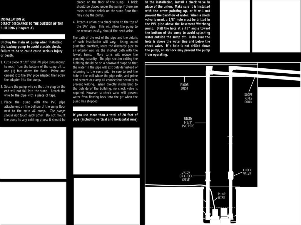
10 Pump & Pipe Installation Instructions Diagram A Page 9
11 Pump & Pipe Installation Instructions Page 10
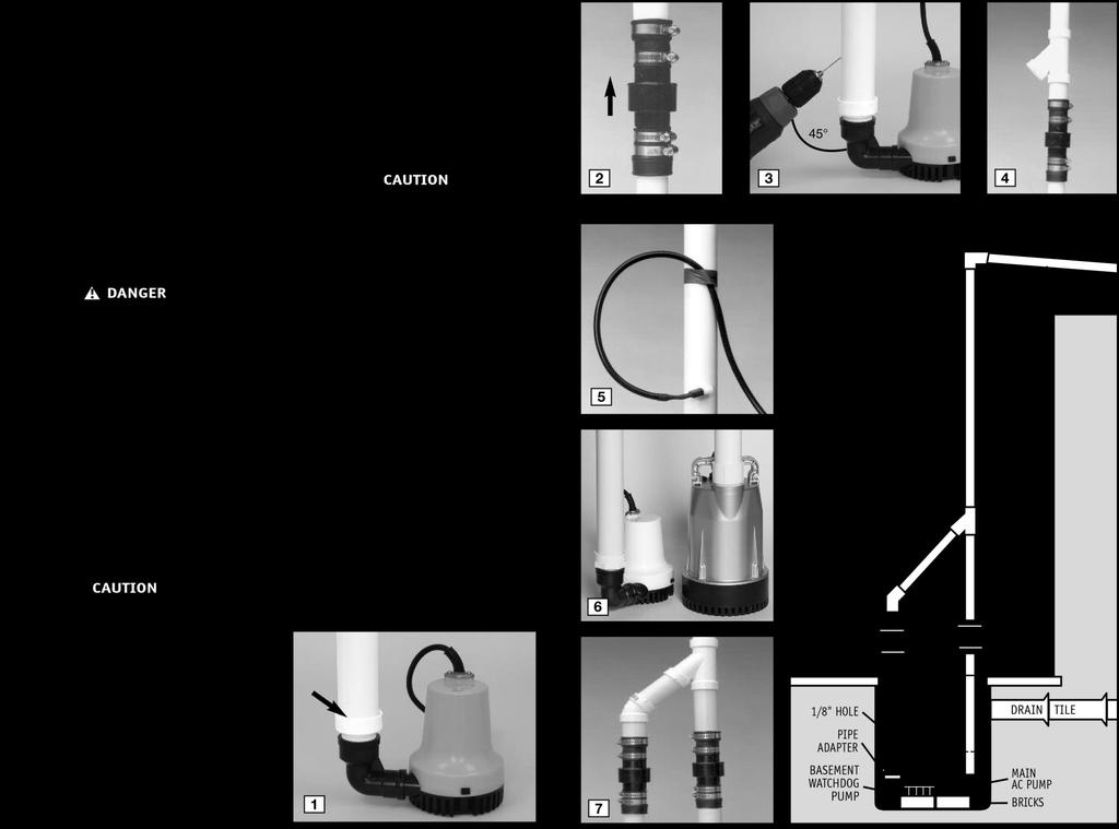
12 Pump & Pipe Installation Instructions INSTALLATION C: DIRECT DISCHARGE TO THE OUTSIDE OF THE BUILDING FOR NARROW SUMP PITS (Diagram C)! DANGER Unplug the main AC pump when installing the backup pump to avoid electric shock. Failure to do so could cause serious injury or attached, simply press the rest of the pump onto the mounted strainer. Diagram B 3. Secure the pump wire so that the plug on the end will not fall into the sump. Attach the wire to the pipe with a piece of tape. Page 11


13 Pump & Pipe Installation Instructions 4. Cut a piece of 1½ rigid PVC pipe long enough to reach from the elbow of the backup pump to one (1) foot above the floor. Prime and cement it to the 1½ pipe adapter, then screw the adapter into the pump.
14 the outside of the building, no check valve is required. However, a check valve will prevent water from flowing back into the pit when the pump has stopped. Pump & Pipe Installation Instructions CAUTION If you use more than a total of 20 feet of pipe (including vertical and horizontal runs) in the installation, install a check valve in place of air lock may sump to avoid splashing water outside the D i a g r a m C arrow pointing up or it will not prevent the backflow of water. When a check valve is used, a 1/8 hole must be drilled in the PVC pipe above the Basement Watchdog pump. Drill the hole at a 45 angle toward the bottom of the sump pit. Make sure the hole is above the water line, and below the check valve. If a hole is not drilled above the pump, an Page 13

 stainless steel hose clamps. Position the bracket so the bottom of the L is just above the top of the main pump, and out of the way of any float switch on the main pump.")
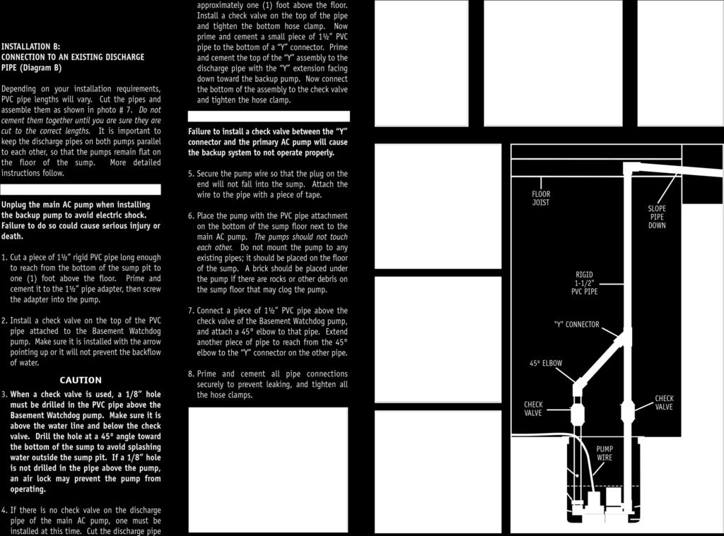
15 Installation Instructions Pump & Pipe INSTALLATION D: CONNECTION TO EXISTING DISCHARGE PIPE FOR NARROW SUMP PITS (Diagram D) Depending on your installation requirements, PVC pipe lengths will vary. Cut the pipes and assemble them as shown in photo # 8. Do not cement them together until you are sure they are cut to the correct lengths. It is important to keep the discharge pipes on both pumps parallel to each other, so that the pumps remain flat on the floor of the sump. More detailed instructions follow. the main AC pump with two (2) stainless steel hose clamps. Position the bracket so the bottom of the L is just above the top of the main pump, and out of the way of any float switch on the main pump. 2. (a) Remove the black bottom strainer of the pump by pressing in the two tabs on the strainer and pushing down. There are holes suitable for mounting on the bottom of the strainer. (b) Using the # 8-32 x ¾ stainless screw, washer and nut, attach the strainer to the L bracket. (c) Once the strainer is attached, simply press the rest of the pump onto the mounted strainer. 3. Secure the pump wire so that the plug on the end will not fall into the sump. Attach the wire to the pipe with a piece of tape. 5. Install a check valve on the top of the PVC pipe attached to the Basement Watchdog pump. Make sure it is installed with the arrow pointing up or it will not prevent the backflow of water. CAUTION 6. When a check valve is used, a 1/8 hole must be drilled in the PVC pipe above the Basement Watchdog pump. Make sure it is above the water line and below the check valve. Drill the hole at a 45º angle toward the bottom of the sump to avoid splashing water outside the sump pit. If a 1/8 hole is not drilled above the pump, an air lock may prevent the pump from operating. pipe with the Y extension facing down toward the backup pump. Now connect the bottom of the assembly to the check valve and tighten the hose clamp. CAUTION Failure to install a check valve between the Y connector and the primary AC Page 14
16 pump will cause the backup system to not operate properly. 8. Connect a piece of 1½ PVC pipe above the check valve of the Basement Watchdog pump, and attach a 45 elbow to that pipe. Extend another piece of pipe to reach from the 45 elbow to the Y connector on the other pipe. 9. Prime and cement all pipe connections securely to prevent leaking, and tighten all the hose clamps. Page 15 Diagram D Battery Instructions The Basement Watchdog Emergency Standby Battery has been designed to run this system for 50 hours, based on a 10% duty cycle. However, most of the time the pump will turn on and off, and the battery will run the pump intermittently for days. In addition, the unique materials in the battery enable it to last longer in standby service. To extend the run time of the pump, use the Basement Watchdog 7.5 Hour Standby Battery. It will run this pump for 100 hours, based on a 10% duty cycle. Why will it run longer? Because the 7.5 hour battery is rated for other Basement Watchdog pumps that draw more power (amps). The emergency pump puts less drain on the battery, so the battery lasts longer. CAUTION The use of automotive batteries is NOT recommended. Automotive batteries are not designed for this application. They will only run the pump for a short time and will have a shorter life than a standby battery. The battery fluid sensor is designed to fit the Basement Watchdog Standby batteries. Measuring the battery fluid is one of the most important features of the system, since about 80% of backup sump pump failures are the result of a battery that has dried out. The internal construction of some wet cell batteries may not be compatible with this system. The use of a Basement Watchdog battery is HIGHLY recommended.! DANGER Do not insert the fluid sensor into any battery except a Basement Watchdog battery. Do not drill a hole in another brand of battery to accommodate the fluid sensor. Do not use the enclosed battery cap on any battery except a Basement Watchdog battery. Do not drill a hole in the cap of another brand of battery to accommodate the fluid sensor. Batteries emit explosive gases, which can cause serious injury or death.! DANGER/POISON


17 PREPARING THE BASEMENT Page 16

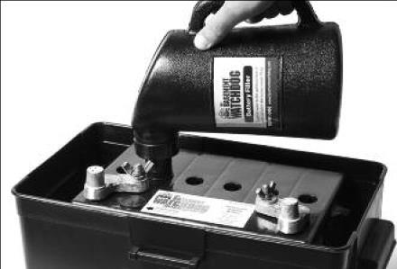
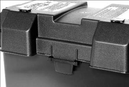
18 WATCHDOG STANDBY BATTERY The Basement Watchdog Standby batteries are shipped dry (without acid) so they never lose power before you take them home. A battery is activated when the acid is added, and then it slowly begins to deteriorate as it ages. By adding the acid just before use, the battery will always be fresh. Use specific gravity battery acid to fill the battery. It is available where you purchased the battery. NOTE: BASEMENT WATCHDOG BATTERIES NOW COME IN TWO CONFIGURATIONS. THE TOPS OF If your battery looks like the battery above, follow these instructions: 1. Remove the battery box top by pushing in the tabs on the front and back of the box and lifting up. 2. Place the battery box on the floor. Place the dry (unfilled) battery into the battery box. Remove the two battery caps by carefully prying them up with a screwdriver as shown on the right. Place the screwdriver in the middle of the cap on the top of the battery. DO NOT lift the cap by prying it up from the groove on the back of the cap. It may damage the vent. 3. Carefully push in the perforated tab at the top of the acid pack. Lift up the large tab and pull out the dispensing hose. Hold the hose upright above the pack and squeeze the hose forcing all the acid back into the pack. Page 17 THE BATTERIES LOOK DIFFERENT, AND THE DIRECTIONS FOR FILLING THE BATTERIES AND CONNECTING THE FLUID SENSOR WILL VARY SLIGHTLY. IF THE TOP OF YOUR BATTERY LOOKS LIKE PHOTO A, FOLLOW THE INSTRUCTIONS ON THIS PAGE. IF THE TOP OF YOUR BATTERY LOOKS LIKE PHOTO B ON PAGE 9, FOLLOW THE INSTRUCTIONS ON PAGE 9. Contains sulfuric acid. Wear eye and clothing protection. If battery acid contacts skin or clothing, wash immediately with soap and water. If acid enters eyes, flush with water for Position the acid pack and battery as shown at the right. Pinch the end of the hose together and cut off the tip. Insert the end of the hose into each cell. Control the flow by pinching the hose with thumb and forefinger. Fill each cell of the battery to a level just covering the battery plates, and then go back and top off each cell equally. It is important to have all the cells filled equally or the battery will not operate properly. The acid should reach a level about ¼ below the cap ring as shown in the diagram at right. DO NOT OVERFILL THE BATTERY. (Diagram E) A newly filled battery will sometimes require additional acid after about 20 minutes. Reexamine the fill level, and add additional acid if necessary. The battery acid may bubble at this time and give off a sulfur-like smell, but this is normal. After the battery has been filled, press the caps securely on the top of the battery. CAUTION When you fill the battery for the FIRST time, it will be the ONLY time you add acid to the battery. In the future, when the fluid level is low, add distilled water to the cells. NEVER add more acid. minutes, and get prompt medical attention. Review the safety instructions on page 1. TO FILL THE BATTERY 1. Remove the cover of the battery box by pushing in the tabs on the front and back of the box and lifting up. 2. Place the battery box on the floor. Place the dry (unfilled) battery into the battery box. Remove the foil seal on the top of the battery. 3. Carefully push in the perforated tab at the top of the acid pack. Lift up the large tab and pull out the dispensing hose. Hold the hose upright above the pack and squeeze the hose forcing all the acid back into the pack. 4. Position the acid pack and battery as shown at the right. Pinch the end of the hose together and cut off the tip. Insert the end of the hose into each cell. Control the flow by pinching the hose with thumb and
.")
 post of the battery or the alarm will sound continuously. The system will NOT warn you if the fluid level is low in this configuration.")
 post of the battery or the alarm will sound continuously.")


 Thread one plastic wire tie through the two mounting brackets on the back of the control unit.")
19 Battery Maintenance Measuring the battery fluid level is one of the most important features of the system. It is important to check the battery fluid levels at least once every 4-6 months. Detailed instructions on adding distilled water to the battery can be found within the Understanding the Warnings & Alarms section of this manual (page 11, 2 Water). If you are not using a Basement Watchdog standby battery, you cannot use the battery fluid sensor. You will need to attach the fluid sensor to the POSITIVE (+) post of the battery or the alarm will sound continuously. The system will NOT warn you if the fluid level is low in this configuration. You will need to check your battery every couple of months to see if it needs water. If the battery dries out, the system will not work. If you are using a maintenance free battery or sealed AGM battery you will also need to attach the fluid sensor to the POSITIVE (+) post of the battery or the alarm will sound continuously. Control Unit Connections! DANGER Risk of electrical shock or battery explosion, which can cause serious injury or death. Unplug the main AC pump to avoid electrical shock. Wear eye protection. Work in a wellventilated area. Do not smoke or allow a spark or flame in the vicinity of the battery. Avoid dropping metal tools on the battery. If battery acid contacts eyes, flush with water for 15 minutes and get prompt medical attention. Review the safety instructions on page 1. When you position the control unit on the discharge pipe, be sure the charger cord will reach the AC power outlet, and the pump cable and the float switch will reach the bottom of the sump. Position the unit in a well-ventilated area. Do not place anything on top of the battery. (Diagram F) 1. Mounting the control unit: (a) Thread one plastic wire tie through the two mounting brackets on the back of the control unit. (b) Secure the controller to the discharge pipe of the Basement Watchdog pump by wrapping the tie around the pipe and pulling it tight. 2. Positioning the dual float switch: The float switch will activate the pump when the water raises either float, and it will remain running as long as the water is above the float. When the water drops below the float switch, an internal timer in the control unit will keep the pump running an additional 45 seconds to empty the sump pit. The switch should be mounted about six (6) inches above the water level line in the sump pit. Attach the float switch very securely to the discharge pipe with the plastic wire tie. Be sure the switch is positioned vertically with the mounting bracket at the top. Do not tilt the switch. Do not position the float switch on the side of the discharge pipe facing the drain tile or any incoming rush of water! 3. Connecting the pump: Remove the security tag from the pump and plug the pump wires into the pump connector on the back of the control unit. Keep the backup pump wire, the AC pump wire, and the float wire separate from each other. Do not let them cross on the final installation. 4. Installing the battery fluid sensor: BASEMENT WATCHDOG BATTERIES COME IN TWO CONFIGURATIONS. THE HOLE FOR THE Page 18
 to remove any hydrogen or oxygen gas that may have been emitted from the battery.")

20 FLUID SENSOR IS MARKED BY AN ARROW ON THE TOP OF EACH BATTERY. Remove the cover of the battery box by pushing in the tabs on the front and back, then lifting up. Fan the area around the top of the battery with a piece of cardboard (or another non-metallic material) to remove any hydrogen or oxygen gas that may have been emitted from the battery. (a) If the top of the battery has six small by an arrow on the top label. Hold the sensor straight up and press it firmly into the hole. Do not bend the sensor. CAUTION If you are not using the Basement Watchdog Standby battery, you cannot use the battery fluid sensor. However, you must attach the sensor to the POSITIVE (+) post of the battery or the alarm will sound continuously. The Basement the battery or the alarm will sound continuously. 5. Connecting the battery: Remove the wing nuts from the battery terminals. Remove the security tag from the battery cables. Attach the battery cables to the battery the WHITE wire to the NEGATIVE (-) post, and the BLACK wire to the POSITIVE (+) post. Replace the wing nuts and tighten them. 9. BE SURE TO PLUG IN THE MAIN AC PUMP WHEN YOU COMPLETE THE INSTALLATION. Understanding the Warnings & Alarms The Basement Watchdog control unit features a series of warning lights that pinpoint potential problems. In addition, an alarm sounds to alert you to the problem. battery caps, replace the battery cap that is 2nd from the POSITIVE (+) post with the battery cap that is provided in the Basement Watchdog package. An arrow on the top of the battery marks this position. There are two holes in this battery cap. Insert the fluid sensor in the hole that is off-center on the top of the cap. Do not glue the sensor into the cap. (b) If the top of the battery has two large caps, place the fluid sensor in the hole molded on the top of the battery. It is located in the second cell from the positive post, and the location is marked Watchdog sump pump system will not warn you if the fluid level is low in this configuration. You will need to check your battery every couple of months to see if it needs water. If the battery dries out, the system will not work. If you are using a maintenance free battery or sealed AGM battery you will also need to attach the fluid sensor to the POSITIVE (+) post of 6. Connecting the charger: Immediately plug the charger into the charger hole on the back of the control unit, then into an AC outlet on the wall. (You should provide additional protection for the control unit by using a surge protector). 7. If the pump alarm is sounding, press the WHITE button to silence the alarm. 8. Secure the cover on the battery box by slipping the tabs through the fittings on the front and back of the box. In some cases the lights and alarm will go off automatically when the problem has been solved. In others, the WHITE button must be pushed to silence the alarm. Refer to the table below for a quick review of the features and their corresponding alarm status. Warning Alarm can be silenced before problem is corrected Alarm shuts off automatically when the problem is corrected Page 19


21 ! DANGER Power Yes Yes Alarm Water No Yes Alarm Pump Yes No, push the Alarm WHITE button System Light Battery Alarm No alarm No SILENCING THE ALARM No alarm Yes DURING AN EMERGENCY The Water 2 and Battery 5alarms cannot power draw from other appliances on the same circuit. Reduce the number of appliances on the circuit. The Basement Watchdog Emergency system is equipped with a switch that will silence the audible alarm during an extended emergency. The Power 1 and 1 Power There are several causes for power failure. The most common is a power outage by your electric company. During this emergency, the Basement Watchdog system will automatically switch to battery power and protect your basement from flooding. Pump 3 alarms can be silenced during a power outage or during heavy rains when the pump is activated repeatedly If the power is on in the rest of the house, check the home circuit breaker or fuse box for failure, and correct the problem. 2. Check the charger. Make sure it is securely plugged into the wall outlet. Make sure the outlet is working properly. 3. Check the charger plug that fits into the rear panel of the control unit. Make sure it is securely plugged into the control unit. The control unit must receive 115 volts AC +/- 5% from the AC outlet. Any voltage lower than 110 volts will activate the Power alarm. Lower voltages can be caused by utility company brown outs or a heavy Page 20

22 If all the connections are secure and the wall Page 21 6 a


23 outlet is operating, but the Power warning light is still on, replace the charger unit with the Basement Watchdog part number Contact Glentronics at , option #3. allow a spark or flame in the vicinity of the battery. Avoid dropping metal tools on the battery. If battery acid contacts eyes, flush with water for 15 minutes and get prompt medical attention. Review the safety instructions on page 1. fluid levels should be checked once every four to six months. REFILLING THE BATTERY 1. Unplug the charger from the wall outlet. that may have been emitted from the battery. 4. Then unscrew the wing nuts and remove the battery cables and the fluid sensor from the battery. 2 Water Risk of electrical shock or battery explosion, which can cause serious injury or death. Wear eye protection. Work in a wellventilated area. Do not smoke or recommended. NEVER ADD MORE ACID. Fill the battery to level 2 as shown in Diagram E on page 8. (The Basement Watchdog battery filler will automatically fill the level to the correct height. See enclosed order form.) 6. Replace the battery caps. Replace the fluid sensor in the hole on the top of the battery or in the battery cap, depending on which battery you own. Be sure the fluid sensor is positioned in the 2nd cell from the positive post. The hole is marked with an arrow. 7. Replace the battery cables the WHITE wire to the NEGATIVE (-) post, and the BLACK wire to the POSITIVE (+) post. Replace the wing nuts and tighten. REFER TO THE PHOTOS AT RIGHT If this warning light and alarm are on, you need to add distilled water to the battery. (This alarm cannot be silenced. When the battery is refilled and the sensor is replaced, the alarm will go off automatically. Battery 6 b 7 2. Remove the cover of the battery box by pushing in the tabs on the front and back, then lifting up. 3. Fan the area around the top of the battery with a piece of cardboard (or another nonmetallic material) to remove any hydrogen or oxygen gas Check the main AC pump for failure. It may not be working, the float switch may be stuck, or it may be too small to handle the inflow of water. Make sure the check valve is working and installed correctly. Make sure the discharge pipe is not clogged or frozen. If the power was out, the backup pump was automatically activated. You need to push the WHITE button on the front of the control panel to reset the alarm. REPLACING THE PUMP! DANGER Unplug the main AC pump when installing or servicing the backup pump to avoid electric shock. Failure to do so could cause serious injury or death. Review the safety instructions on page Remove the battery caps. Add distilled water to each cell. If distilled water is not available, tap water with a low mineral content may be used. Well water is not that may have been emitted from the battery. 8. Replace the cover of the battery box. 9. Plug the charger back into the outlet. (You should provide additional protection for the control unit by using a surge protector.) 10. If any of the alarms are sounding, press thewhite button on the front of the control panel for one (1) second. 3 Pump When the water rises in the sump pit and activates the float switch, the pump will begin pumping, and the Pump light and alarm will turn on. The alarm stays on to alert you to the fact that the standby system was used to empty water from the sump. Try to determine what caused the system to activate. REFER TO PHOTOS BELOW 1. Unplug the charger from the wall outlet. 2. Remove the cover of the battery box by pushing in the tabs on the front and back, then lifting up. 3. Fan the area around the top of the battery with a piece of cardboard (or another nonmetallic material) to remove any hydrogen or oxygen gas Page 22


24 4. Remove the fluid sensor from the top of the battery. Unscrew the wing nuts and remove the battery cables from the battery. 5. Unplug the pump from the back of the control unit. 6. Release the union or check valve and remove the pump and the rigid PVC pipe section from the sump pit. 7. Unscrew the pipe and adapter from the old pump, and screw them into the new pump. 8. Lower the pump into the sump and reconnect the union or check valve Page 23
 post, and then the BLACK wire to the POSITIVE (+) post. Tighten the wing nuts. 11. Replace the cover of the battery box.")
 second to silence them. 4 System This green light should always be flashing.")

25 Plug the pump wires into the back of the control unit. 10. Replace the fluid sensor in the top of thebattery. Connect the battery cables to the battery the WHITE wire to the NEGATIVE (-) post, and then the BLACK wire to the POSITIVE (+) post. Tighten the wing nuts. 11. Replace the cover of the battery box. 12. Plug the charger and the main AC pump backinto the wall outlet. (You should provide additional protection for the controller by using a surge protector). 13. If any alarms are sounding, press the WHITEbutton on the front of the control unit for one (1) second to silence them. 4 System This green light should always be flashing. It indicates that the system is operating. It will flash when there is power coming from either the battery or the AC outlet. 5 Battery This light and alarm will come on when the control unit detects there is less than ½ hour of pumping power left in the battery, or that the battery is defective. The alarm cannot be silenced, because action needs to be taken to protect your basement. If your battery is more than five (5) years old, replace it. If not, here are several situations that would cause the pump to run the battery for an extended time and discharge the battery: Check the list below before you replace the battery. If the top light on the controller is also on, it means that the unit is not receiving AC power. Either the AC power is out, the circuit breaker has blown, or the outlet is bad. When the problem is corrected, the battery should recharge. If the third light on the controller is also on, check your main pump for failure. The backup pump may have been activated repeatedly if your main AC pump is broken, or you are experiencing heavy rains and your main pump cannot keep up with the inflow of water. You may need to upgrade or replace your main pump. When the problem is corrected, the battery should recharge. If no other lights are on, this means the terminals may be corroded, and the battery cannot charge properly. Unplug the charger from the wall outlet. Then, check the battery cables and the battery terminals for corrosion. Clean and tighten them as needed. The procedure is described at the right. If the battery terminals have been cleaned and the light is still on, there could be a problem with the controller or the battery. The best way to determine if the battery is the problem is to have it charged and load tested at any local car service station. If the battery is bad and less than one (1) year old, it can be returned to the place of purchase for a replacement (receipt required). If the battery is good, contact Glentronics service department for further instructions. The phone number is , option #3. If the battery alarm goes on while the pump is running and the power is out, you will have a minimum of one-half (1/2) hour of continuous pumping time to replace the battery. (In most cases, the pump does not run continuously, and therefore, you actually have a longer time to replace it.) You will not be able to silence the alarm. Left unattended, the basement will flood. In a severe emergency, if a replacement battery is not available, you could temporarily use your car battery, or recharge this battery by connecting it to your car battery. Once the AC power is restored, the battery will recharge automatically, unless it is old or damaged. The alarm will turn off when the AC power is restored and the pumping energy reaches one-half (1/2) hour or more. In the event that your Basement Watchdog sump pump system has pumped for an extended period of time, the battery may be very depleted. In this condition, when the AC power is returned to the unit, a battery alarm will continue to sound. The battery may need a longer period to recharge. For a faster recharge, an automotive or marine battery charger can be used to recharge the battery. Follow the manufacturer s instructions and safety information included with the charger.! WARNING When another charger is used, first disconnect the Basement Watchdog charger from the control unit, and then disconnect the control unit from the battery. Using another charger without disconnecting the control unit will destroy the control unit and void the warranty. TO CLEAN THE BATTERY TERMINALS AND CABLES! DANGER Risk of electrical shock or battery explosion, which can cause serious injury or death. Wear eye protection. Work in a well-ventilated area. Do not smoke or allow a spark or flame in the vicinity of the battery. Avoid dropping metal tools on the battery. If battery acid contacts eyes, flush with water for 15 minutes and get prompt medical attention. Review the safety instructions on page 1. REFER TO THE PHOTOS BELOW AND AT RIGHT 1. Unplug the charger from the wall outlet. Page 24
 to remove any hydrogen or oxygen gas that may have been emitted from the battery. 4.")
26 2. Remove the cover of the battery box by pushing in the tabs on the front and back, then lifting up. 3. Fan the area around the top of the battery with a piece of cardboard (or another nonmetallic material) to remove any hydrogen or oxygen gas that may have been emitted from the battery. 4. Remove the fluid sensor from the top of the battery. Unscrew the wing nuts. Remove the battery cables. 2 3 Page 25
27 ! DANGER Page 26


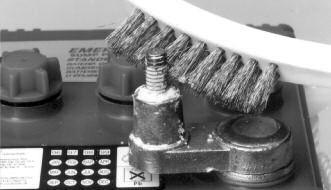
28 Clean the battery posts with a battery terminal cleaner or a wire brush. ( ( a Page b
29 6. Clean any corrosion off of the ring connectors on the ends of the battery wires. Use a stiff brush or sandpaper. DO NOT apply corrosion resisting sprays or pads to the terminal rings or posts after you have cleaned them, since this could prevent the battery from charging properly. 7. Replace the fluid sensor in the top of the battery. Replace the battery cables, WHITE to the NEGATIVE (-) post and BLACK to the POSITIVE (+) post. Tighten the wing nuts. 8. Plug the charger back into the wall outlet. (You should provide additional protection for the control unit by using a surge protector.) 9. If any of the alarms are sounding, press the WHITE button on the front of the control panel for one (1) second. REPLACING THE BATTERY Risk of electrical shock or battery explosion, which can cause serious injury or death. Wear eye protection. Work in a well-ventilated area. Do not smoke or allow a spark or flame in the vicinity of the battery. Avoid dropping metal tools on the battery. If battery acid contacts eyes, flush with water for 15 minutes and get prompt medical attention. Review the safety instructions on page 1. REFER TO THE PHOTOS AT RIGHT 1. Unplug the charger from the wall outlet. 2. Remove the cover of the battery box by pushing in the tabs on the front and back, then lifting up. 3. Fan the area around the top of the battery with a piece of cardboard (or another non- Page 28
 second. TEST/RESET BUTTON The TEST button may be used to check the pump and system.")

30 Plug the charger back into the wall outlet. (You should provide additional protection for the control unit by using a surge protector.) 10. If any of the alarms are sounding, press thewhite button on the front of the control panel for one (1) second. TEST/RESET BUTTON The TEST button may be used to check the pump and system. Push the TEST button. This will activate the pump for as long as you hold the button. It will stop as soon as you let go of the button. While the pump is active, water will come out of the 1/8 hole that was drilled into the PVC discharge pipe.. This is normal. This hole is needed to prevent an air lock within the system. DO NOT obstruct the hole or an air lock may prevent the system form activating. TESTING THE FLOAT SWITCH It is important to manually test the float switch periodically or after any maintenance.! DANGER Unplug the main AC pump when installing or servicing the backup pump to avoid electric shock. Failure to do so could cause serious injury or death. Review the safety instructions on page 1. Lift the float up and let go. This will activate the pump. The control unit will run the pump for approximately 45 seconds so it can empty all the water in the sump pit. While the pump is active, water will come out of the 1/8 hole that was drilled into the PVC discharge pipe. This is normal. The hole is needed to prevent an air lock within the system. DO NOT obstruct the hole or an air lock may prevent the system from activating. If there is no water in the pit, the pump can run dry for this amount of time. The alarm will sound and the Pump light will go on. Push the WHITE button on the front of the control panel to reset the alarm. BE SURE TO PLUG IN THE MAIN AC PUMP WHEN YOU HAVE COMPLETED THE TEST. MAINTENANCE CHECK LIST Maintenance should be performed 1-2 times per year. 1. Lift the float switch as described at left. 2. Remove all debris from the bottom of thepit and pump strainer. 3. Remove all debris from the water. 4. Remove all debris from the float switch. 5. Fill the pit with water. Make sure thepump turns on at the intended level. 6. While the pump is running, make sure thepump is evacuating water at a good pace and water is coming out of the 1/8 air bleed hole. 7. Remove the fluid sensor and cap from thebattery and rinse any residue buildup from the battery cap. Replace the cap and fluid sensor. 8. Check battery fluid levels once every fourto six months. 9. Check and clean battery terminals. PARTS & SERVICE INFORMATION You can receive technical support, or order parts by calling Glentronics, Inc. at , option #3, or by visiting the Basement Watchdog website at Send your unit to the following address if repairs are needed: Glentronics, Inc. 645 Heathrow Drive Lincolnshire, IL Page 29
31 Installation Instructions Troubleshooting Guide DANGER Read safety warnings & instructions before attempting any repairs or maintenance. Possible Reasons Remedies Power outage None. The backup pump will run on the battery An outlet, fuse or circuit breaker has failed. Try another outlet, replace the fuse or reset the circuit breaker The power cord is unplugged from the wall. Make sure the power cord is plugged in securely The charger is receiving less than 110 volts from the outlet None, if the utility company has instigated brown outs. Otherwise, reduce the number of other appliances on the circuit BATTERY FLUID LOW Possible Reasons Remedies The battery fluid is low Add distilled water to the battery PUMP WAS ACTIVATED Possible Reasons Remedies The main AC pump failed because of a power outage None. The backup pump was activated The main AC pump is broken Replace the main AC pump The float switch on the main pump is jammed or defective Free the float switch or replace it The main AC pump could not keep up with the inflow of water None. The backup pump was activated. If this is a recurring problem, install a higher capacity main pump The check valve is stuck or installed improperly and the water returns to the sump pit Replace the check valve or correct the installation The discharge pipe is blocked and the water returns to the sump pit Clean out or replace the discharge pipe BATTERY PROBLEM Possible Reasons Remedies Terminals are corroded Clean terminals & cables Cables are loose Tighten wing nuts Battery is discharged Replace battery if power is out. There is only 1/2 hour of continuous pumping power left. Battery will recharge when power is restored Battery is damaged or old Replace battery Page 30
32 LIMITED WARRANTY Page 31 If the above solutions do not resolve the problem, follow the instructions within this manual to disconnect the system from the outlet and battery terminals, then reconnect the system and push the reset button. If the problem continues, contact customer service. By opening this package and using this GLENTRONICS, INC. product, you are agreeing to be bound by the terms of the GLENTRONICS, INC. limited warranty ( warranty ) as set out below. Do not use your product until you have read the terms of the warranty. If you do not agree to the terms of the warranty, do not use the product and return it within the return period stated on your purchase receipt from the retail store or authorized distributor where you purchased it for a refund. To the extent permitted by law, this warranty and the remedies set forth are exclusive and in lieu of all other warranties, remedies and conditions, whether oral, written, statutory, express or implied. GLENTRONICS, INC. disclaims all statutory and implied warranties, including without limitation, warranties of merchantability and fitness for a particular purpose and warranties against hidden or latent defects, to the extent permitted by law. GLENTRONICS, INC. will not be liable for any incidental, special or consequential damages for breach of any express or implied warranties on this product. In so far as such warranties cannot be disclaimed, GLENTRONICS, INC. limits the duration and remedies of such warranties to the duration of this express warranty and, AT GLENTRONICS, INC.'s option, the repair or replacement services described below. Some states (countries and provinces) do not allow limitations on how long an implied warranty (or condition) may last, so the limitation described above may not apply to you. Any and all causes of action arising from, filed as a result of or in reference to, this warranty or the products described under this warranty shall be governed by and construed under the laws of the State of Illinois. Any cause of action arising from, filed as a result of or in reference to, this warranty or the products described under this warranty shall be filed only in the Circuit Court of the 18th Judicial District, Lake County, Waukegan, Illinois, or in the Northern District of Illinois if filed in Federal Court. The maximum liability for any product described in this warranty shall be the cost of product replacement only. If any term is held to be illegal or unenforceable, the legality or enforceability of the remaining terms shall not be affected or impaired. What is Covered by this Warranty? GLENTRONICS, INC. warrants to the end purchaser that its pumps, switch and control unit products are free from defective materials and workmanship for the periods indicated below: All parts and labor (excluding installation) for a period of: 2 years from the date of purchase, when used intermittently as a sump pump The defective product must be returned directly to the factory, postage prepaid with the original bill of sale or receipt to the address listed below. GLENTRONICS, INC., at its option, will either repair or replace the product and return it postage prepaid. What is NOT Covered by this Warranty? This warranty does not cover the cost or value of damaged property, including expressly any property that has been affected by water overflow, seepage or flooding. If GLENTRONICS, INC. determines that a product is deemed defective under this warranty agreement, it will repair or replace the PRODUCT ONLY. GLENTRONICS, INC. will not cover the cost to reinstall the product, nor will GLENTRONICS, INC. pay the cost of having a plumber or contractor repair or replace the product. GLENTRONICS, INC. will not repair or replace a product that was installed incorrectly. A product shall be considered installed incorrectly when it deviates in any way from the instructions described in this manual. This warranty does not cover product problems resulting from handling liquids hotter than 104 degrees Fahrenheit, handling inflammable liquids, solvents, strong chemicals or severe abrasive solutions; user abuse; misuse, neglect, improper maintenance, commercial or industrial use; improper connection or installation, damages caused by lightning strikes; excessive surges in AC line voltage; water damage to the controller; other acts of nature, or failure to operate in accordance with the enclosed written instructions. How to Obtain Warranty Service Within thirty (30) days of the product s defective performance, the unit must be shipped, freight prepaid, or delivered to GLENTRONICS, INC. to provide the services described hereunder in either its original carton and inserts, or a similar package affording an equal degree of protection. Products not received by GLENTRONICS, INC. at the address indicated below within thirty (30) days of the product s defective performance will not be considered for warranty service. Products received after two (2) years from the date of purchase, fall outside of the timeframe for warranty service and will not be eligible for warranty service. The product must be returned to GLENTRONICS, INC. for inspection in order to be considered for warranty service. If the product is not returned to GLENTRONICS, INC. or the product is inspected by any person, plumber, contractor or business other than GLENTRONICS, INC., this warranty shall no longer be valid. Prior to defective operation, the unit must not have been previously altered, repaired or serviced by anyone other than GLENTRONICS, INC., or its agent; the serial number on the unit must not have been altered or removed;


33 the unit must not have been subject to accident, misuse, abuse or operated contrary to the instructions contained in the accompanying manual. The dealer's dated bill of sale, or installer s invoice must be retained as evidence of the date of purchase and to establish warranty eligibility. Where are Products Sent for Warranty Service? Glentronics, Inc., 645 Heathrow Drive, Lincolnshire, IL How Can I Obtain More Information? By calling CHECK OUT THESE OTHER BASEMENT WATCHDOG PRODUCTS AC PUMPS Industrial grade pumps for the residential market The Basement Watchdog line of AC sump pumps is strong, dependable and so energy efficient, they could pay for themselves in a few years. The sump pumps are equipped with dual float switches for added reliability. When your main AC pump needs replacement, consider upgrading to one of the pumps in the Basement Watchdog line. FLOAT SWITCHES What s the most common reason your main AC pump fails? It s probably the result of a float switch that is stuck or broken. Replace it with a Basement Watchdog dual float and controller for reliable operation. The dual float has, not one, but two floats mounted within a protective cage. Should one float fail to operate, the second float automatically activates the pump. The protective cage prevents debris or other wires from interfering with the movement of the float. It can be used to replace the float on most AC pumps. muffle the sound. It works just like a conventional check valve, only quieter. CHECK VALVES What s a Klunkless Check Valve? If you ve spent any time in your basement, you ve probably noticed your sump pump turning on and off with a loud clunk. That s the result of the water pressure slamming the valve closed in the check valve. The Klunkless Check Valve has a built-in air chamber to counteract that pressure and WATER ALARMS Minimize the risk of water damage You can detect leaks before they become bigger problems by placing a water alarm wherever there is a risk of water damage in the utility room, laundry room, kitchen, bathroom or basement. The alarm will sound when as little as 1/32 of water reaches the sensor. Page 32
Battery Backup Sump Pump System
 Instruction Manual & Safety Warnings Table of Contents Important Safety Warnings and Instructions Electrical precautions 1 Battery preparation 1 Battery precautions 1 Introduction Items included in system
Battery Backup Sump Pump System
 Table of Contents Instruction Manual & Safety Warnings Important Safety Warnings and Instructions Electrical precautions 1 Battery preparation 1 Battery precautions 1 Introduction Items included in system
Battery Backup Sump Pump System
 Table of Contents Instruction Manual & Safety Warnings Important Safety Warnings and Instructions Electrical precautions 1 Battery preparation 1 Battery precautions 1 Introduction Items included in system
Battery Backup Sump Pump System
 Battery Backup Sump Pump System Instruction Manual & Safety Warnings Table of Contents Important Safety Warnings and Instructions Electrical Precautions 1 Battery Preparation 1 Battery Precautions 1 Introduction
Battery Backup Sump Pump System
 Battery Backup Sump Pump System Instruction Manual & Safety Warnings Table of Contents Important Safety Warnings and Instructions Electrical Precautions 1 Battery Preparation 1 Battery Precautions 1 Introduction
A/C-D/C Battery Backup Sump Pump System
 2400 A/C-D/C Battery Backup Sump Pump System Instruction Manual & Safety Warnings Table of Contents Important Safety Warnings and Instructions Electrical precautions 1 Battery preparation 1 Battery precautions
A/C-D/C Battery Backup Sump Pump System
 A/C-D/C Battery Backup Sump Pump System PUSH to Test or Reset Instruction Manual & Safety Warnings Table of Contents Important Safety Warnings and Instructions Electrical precautions 1 Battery preparation
A/C-D/C Battery Backup Sump Pump System
 A/C-D/C Battery Backup Sump Pump System Instruction Manual & Safety Warnings Table of Contents Important Safety Warnings and Instructions Electrical precautions 1 Battery preparation 1 Battery precautions
A/C-D/C Battery Backup Sump Pump System
 A/C-D/C Battery Backup Sump Pump System Instruction Manual & Safety Warnings Table of Contents Important Safety Warnings and Instructions Electrical precautions 1 Battery preparation 1 Battery precautions
Battery Backup Sump Pump System Instruction Manual
 Battery Backup Sump Pump System Instruction Manual Push button second to test or reset alarm. Push 5 seconds to silence alarm for 24 hours. Warning alarms The fluid in the battery is low. Add distilled
Pro Series C11. Combination Primary and Backup Sump Pump System. Instruction Manual & Safety Warnings. Table of Contents
 Pro Series C11 Combination Primary and Backup Sump Pump System Table of Contents Instruction Manual & Safety Warnings Important Safety Warnings and Instructions Electrical precautions 1 Battery preparation
Pro Series C22. Combination Primary and Backup Sump Pump System. Instruction Manual & Safety Warnings. Table of Contents
 Pro Series C Combination Primary and Backup Sump Pump System Instruction Manual & Safety Warnings Table of Contents Important Safety Warnings and Instructions Electrical precautions 1 Battery preparation
Combination Primary and Backup Sump Pump System
 Combination Primary and Backup Sump Pump System Table of Contents Instruction Manual & Safety Warnings Important Safety Warnings and Instructions Electrical precautions 1 Battery preparation 1 Battery
Pro Series C33. Combination Primary and Backup Sump Pump System. Instruction Manual & Safety Warnings. Table of Contents
 Pro Series C Combination Primary and Backup Sump Pump System Instruction Manual & Safety Warnings Table of Contents Important Safety Warnings and Instructions Electrical precautions 1 Battery preparation
Combination Primary and Backup Sump Pump System
 Combination Primary and Backup Sump Pump System Instruction Manual & Safety Warnings Table of Contents Important Safety Warnings and Instructions Electrical precautions 1 Battery preparation 1 Battery
Combination Primary and Backup Sump Pump System
 Combination Primary and Backup Sump Pump System Instruction Manual & Safety Warnings Table of Contents Important Safety Warnings and Instructions Electrical precautions 1 Battery preparation 1 Battery
Instruction Manual. Computer Controlled A/C - D/C Sump Pump System
 Instruction Manual Computer Controlled A/C - D/C Sump Pump System Table of Contents Important Safety Instructions General.......................1 AC Power Requirements..........1 Personal Precautions.............1
Sump Pumps Instruction Manual & Safety Warnings
 Important Safety Instructions SAVE THESE INSTRUCTIONS. This manual contains important SAFETY WARNINGS and OPERATING INSTRUCTIONS for the Pro Series pumps. You will need to refer to it before attempting
Sewage Pumps Instruction Manual & Safety Warnings
 Important Safety Instructions SAVE THESE INSTRUCTIONS. This manual contains important SAFETY WARNINGS and OPERATING INSTRUCTIONS. You will need to refer to it before attempting any installation or maintenance.
OWNER S MANUAL. Model YUA2AMPCH 2 AMP Dual-Bank Automatic Battery Charger & Maintainer READ ENTIRE MANUAL BEFORE USING THIS PRODUCT
 Model YUA2AMPCH 2 AMP Dual-Bank Automatic Battery Charger & Maintainer Certified by California BCS Regulations OWNER S MANUAL READ ENTIRE MANUAL BEFORE USING THIS PRODUCT READ ENTIRE MANUAL BEFORE USING
Operating Instructions
 Operating Instructions PRO- If you sell, inventory or service lead-acid batteries, you want the battery you take off the shelf to be as new as the day it was manufactured. However, batteries that sit idle
801 BUSINESS CENTER DRIVE MOUNT PROSPECT, ILLINOIS
 280-600 Send Warranty Product Repairs to: 1025 E. Thompson Ave., Hoopeston, IL 60942-0280. Call Customer Service if you have questions: 1-800-621-5485 A. IMPORTANT SAFETY INSTRUCTIONS 1. SAVE THESE INSTRUCTIONS
801 BUSINESS CENTER DRIVE MOUNT PROSPECT, ILLINOIS Ext. 322
 277-999 ELECTRIC CORP. 801 BUSINESS CENTER DRIVE MOUNT PROSPECT, ILLINOIS 800-621-5485 Ext. 322 Send Warranty Product Repairs to: 605 South Vermilion, Suite C, Brownsville, TX 78521-6851 Call Customer
Safety, Installation And Operating Instructions For The Following Battery Charger Models: i2412, i3612, i4809, i2425, i3625, and i4818
 Safety, Installation And Operating Instructions For The Following Battery Charger Models: i2412, i3612, i4809, i2425, i3625, and i4818 IMPORTANT NOTICE: Please save and read these safety, operating and
CRS1, CRS2 and CRS3. For additional information please call our. PRO CHARGING SYSTEMS, LLC 1551 Heil Quaker Boulevard, LaVergne, TN
 CRS1, CRS2 and CRS3 For additional information please call our Technical Support Group 800.742.2740 PRO CHARGING SYSTEMS, LLC 1551 Heil Quaker Boulevard, LaVergne, TN 37086-3539 110310 Installation and
24 VOLT AUTOMATIC BATTERY CHARGER PART NO
 24 VOLT AUTOMATIC BATTERY CHARGER PART NO. 957732 AC Input: DC Output: Battery Type: Specifications 230 volts, 50 hertz, 3.5 amps, single-phase 24 volts, 20 amps initially tapering to 6 amps 24 volt, 12
STEP-BY-STEP INSTALLATION GUIDE
 Battery Backup System STEP-BY-STEP INSTALLATION GUIDE Operating Instructions & Parts Manual ESP25 Please read and save these instructions. Read carefully before attempting to assemble, install, operate
Installation Operation Parts
 OWNER S MANUAL BATTERY BACKUP SUMP Installation Operation Parts For further operating, installation or maintenance assistance, Call 98-8-05 PRINTED IN U.S.A. M-8 (/9) RULES FOR SAFE INSTALLATION AND OPERATION
INSTRUCTION MANUAL. 12-Station HD Shop 12V Portable Battery Charger
 INSTRUCTION MANUAL 12-Station HD Shop 12V Portable Battery Charger IMPORTANT SAFETY INSTRUCTIONS 1. SAVE THESE INSTRUCTIONS This manual contains important safety and operating instructions for your HD
LESTRONIC II BATTERY CHARGER BUILT-IN OR PORTABLE CHARGERS
 LESTRONIC II BATTERY CHARGER BUILT-IN OR PORTABLE CHARGERS PLEASE SAVE THESE IMPORTANT SAFETY AND OPERATING INSTRUCTIONS For correct operation of the equipment, it is important to read and be familiar
Installation and Operating Instructions (for chargers shown below)
") Installation and Operating Instructions (for chargers shown below) For additional information please call our Technical Support Group 800.742.2740 PRO CHARGING SYSTEMS, LLC 1551 Heil Quaker Boulevard,
Installation and Operating Instructions (for chargers shown below) For additional information please call our Technical Support Group 800.742.2740 PRO CHARGING SYSTEMS, LLC 1551 Heil Quaker Boulevard,
LESTRONIC II BATTERY CHARGER MODEL 19740
 *01679* LESTRONIC II BATTERY CHARGER MODEL 19740 PLEASE SAVE THESE IMPORTANT SAFETY AND OPERATING INSTRUCTIONS For correct operation of the equipment, it is important to read and be familiar with this
IMPORTANT SAFETY INSTRUCTIONS IMPORTANT: READ AND SAVE THIS SAFETY AND INSTRUCTION MANUAL. KEEP IT WITH OR NEAR CHARGER AT ALL TIMES.
 IMPORTANT SAFETY INSTRUCTIONS IMPORTANT: READ AND SAVE THIS SAFETY AND INSTRUCTION MANUAL. KEEP IT WITH OR NEAR CHARGER AT ALL TIMES. SPECIFICATIONS: For technical assistance, call your Dealer with the
SUBMERSIBLE SUMP PUMPS
 SUBMERSIBLE SUMP PUMPS Zoeller is a registered trademark of Zoeller Co. All Rights Reserved. MODEL #1099-0001 Español p. 11 ATTACH YOUR RECEIPT HERE Serial Number Purchase Date Questions, problems, missing
Model: SE-4020-CA Automatic Battery Charger
 OWNERS MANUAL Model: SE-4020-CA Automatic Battery Charger PLEASE SAVE THIS OWNERS MANUAL AND READ BEFORE EACH USE. This manual will explain how to use the battery charger safely and effectively. Please
OPERATOR'S MANUAL IMPORTANT SAFETY INSTRUCTIONS
 ASSOCIATED OPERATOR'S MANUAL IMPORTANT SAFETY INSTRUCTIONS MODEL 6366 12 VOLT, 0-20 AMP 4 X 20 BATTERY CHARGER 1. SAVE THESE INSTRUCTIONS. This manual contains important safety and operating instructions
36 VOLT AUTOMATIC BATTERY CHARGER PART NO
 36 VOLT AUTOMATIC BATTERY CHARGER PART NO. 957727 AC Supply: DC Output: Battery Type: Specifications 120 volts, 60 Hertz, 10 amps, single-phase 36 volts, 20 amps initially tapering to 6 amps 36 volt, 18
User Guide IGD Series
 US User Guide IGD Series DANGER PRIOR TO USE, READ AND UNDERSTAND PRODUCT SAFETY INFORMATION. Failure to follow the instructions may result in ELECTRICAL SHOCK, EXPLOSION, or FIRE, which may result in
SP6. Automatic Battery Charger. Model
 Model SP6 Automatic Battery Charger OWNERS MANUAL PLEASE SAVE THIS OWNERS MANUAL AND READ BEFORE EACH USE. This manual will explain how to use the charger safely and effectively. Please read and follow
PEDESTAL SUMP PUMP. MODEL # Español p. 11. Zoeller is a registered trademark of Zoeller Co. All Rights Reserved.
 PEDESTAL SUMP PUMP Zoeller is a registered trademark of Zoeller Co. All Rights Reserved. MODEL #1084-0001 Español p. 11 ATTACH YOUR RECEIPT HERE Serial Number Purchase Date Questions, problems, missing
SUBMERSIBLE SUMP PUMPS
 SUBMERSIBLE SUMP PUMPS Zoeller is a registered trademark of Zoeller Co. All Rights Reserved. MODELS #1073-0001, 1075-0001 Español p. 9 ATTACH YOUR RECEIPT HERE Serial Number Purchase Date Questions, problems,
2/10/50 AMP 12 VOLT BATTERY CHARGER/ ENGINE STARTER
 2/10/50 AMP 12 VOLT BATTERY CHARGER/ ENGINE STARTER WARNING This product contains or, when used, produces a chemical known to the State of California to cause cancer and birth defects or other reproductive
IMPORTANT SAFETY INSTRUCTIONS
 1163714 1.5 AMP 12VOLT TRICKLE 1.5 AUTOMATIC AMP AUTOMATIC TRICKLE 1.5 AMP AUTOMATIC 12V12VOLT BATTERY CHARGER IMPORTANT SAFETY INSTRUCTIONS 1. SAVE THESE INSTRUCTIONS This product offers a wide range
AUTO CHARGE 11 MODEL #: XX. AUTOMATIC BATTERY CHARGER U.L. Configuration INSTRUCTION MANUAL
 INSTRUCTION MANUAL AUTO CHARGE 11 AUTOMATIC BATTERY CHARGER U.L. Configuration MODEL #: 091-11-XX NOTE : This charger is designed for vehicles with dual batteries and negative ground. CAUTION This unit
12V 1 AMP (1000 ma) Automatic Battery Charger & Maintainer
 Automatic Battery Charger & Maintainer") 12V 1 AMP (1000 ma) Automatic Battery Charger & Maintainer For lead-acid batteries THIS MANUAL CONTAINS IMPORTANT SAFETY AND OPERATING INSTRUCTIONS FOR 12V BATTERY CHARGER: YUA1201000 / INT1201000 KEEP
12V 1 AMP (1000 ma) Automatic Battery Charger & Maintainer For lead-acid batteries THIS MANUAL CONTAINS IMPORTANT SAFETY AND OPERATING INSTRUCTIONS FOR 12V BATTERY CHARGER: YUA1201000 / INT1201000 KEEP
Installation and Operating Instructions (for chargers shown below)
") Installation and Operating Instructions (for chargers shown below) For additional information please call our Technical Support Group 800.742.2740 PRO CHARGING SYSTEMS, LLC 1551 Heil Quaker Boulevard,
Installation and Operating Instructions (for chargers shown below) For additional information please call our Technical Support Group 800.742.2740 PRO CHARGING SYSTEMS, LLC 1551 Heil Quaker Boulevard,
MODEL 6017 OPERATOR'S MANUAL
 MODEL 6017 OPERATOR'S MANUAL ASSOCIATE D IMPORTANT SAFETY INSTRUCTIONS 1. SAVE THESE INSTRUCTIONS. This manual contains important safety and operating instructions for the battery charger you have purchased.
10 AMP ON BOARD BATTERY CHARGER
 R A Valley Forge Company MODEL 2611A-1-B 10 AMP ON BOARD BATTERY CHARGER One Output OWNER S MANUAL IMPORTANT! READ THESE INSTRUCTIONS BEFORE INSTALLING AND USING THIS PRODUCT. Keep these instructions for
Models: SP3, SPSS3 Automatic Battery Charger
 OWNERS MANUAL Models: SP3, SPSS3 Automatic Battery Charger PLEASE SAVE THIS OWNERS MANUAL AND READ BEFORE EACH USE. This manual will explain how to use the charger safely and effectively. Please read and
2603 Battery Pal 3 AMP, 1 2 VOLT BATTERY CHARGER
 R 2603 Battery Pal 3 AMP, 1 2 VOLT BATTERY CHARGER Connections at a glance: The GUEST Battery Pal 2603 is designed to recharge your battery, and extend your battery s life in applications where it is stored
installation and operating instructions for the following xtreme Battery chargers:
 installation and operating instructions for the following xtreme Battery chargers: Model Name No. of Banks Amps Per Bank Battery System Dual Pro SE Xtreme Dual Pro Xtreme Three Bank SE Xtreme Three Bank
MODEL 6010A 6 12 VOLT BATTERY CHARGER ASSOCIATE
 MODEL 600A 6 VOLT BATTERY CHARGER ASSOCIATE IMPORTANT SAFETY INSTRUCTIONS. SAVE THESE INSTRUCTIONS. This manual contains important safety and operating instructions for the battery charger you have purchased.
MODEL A97 SERIES. Switchmode Utility Rectifier/Battery Charger ECN/DATE
 MODEL A97 SERIES Switchmode Utility Rectifier/Battery Charger CPN108172 ISSUE DATE: 16071 7/03 ECN/DATE 106 BRADROCK DRIVE DES PLAINES, IL. 60018-1967 (847) 299-1188 FAX: (847)299-3061 Page 1 of 7 INSTRUCTION
HALLMARK INDUSTRIES INC
 Performance Part No. HP. CONVERTIBLE JET PUMP USER S MANUAL GPH of Water @ Total Discharge Pressure of 40 psi Max. Pressure Max suction (shallow well) Max Suction (deep well) Max GPM (@0 head) Max Discharge
GRINDER PUMP MODEL # Zoeller is a registered trademark of Zoeller Co. All Rights Reserved. Español p. 13
 GRINDER PUMP Zoeller is a registered trademark of Zoeller Co. All Rights Reserved. MODEL #2701-0005 Español p. 13 ATTACH YOUR RECEIPT HERE Serial Number Purchase Date Questions, problems, missing parts?
LESTRONIC II BATTERY CHARGER MODEL 07210
 LESTRONIC II BATTERY CHARGER MODEL 07210 PLEASE SAVE THESE IMPORTANT SAFETY AND OPERATING INSTRUCTIONS For correct operation of the equipment, it is important to read and be familiar with this entire manual
POWER TO GET THE JOB DONE
 52722 10 AMP 12 VOLT BATTERY CHARGER OWNER S MANUAL OVERCHARGING PROTECTION 10 Amp, 12 Volt Fully automatic and manually selectable Includes overcharging protection in automatic mode Reverse hook-up protection
10AMP FULLY AUTOMATIC 6V & 12V BATTERY CHARGER OWNER'S MANUAL
 1244502 10AMP FULLY AUTOMATIC 6V & 12V BATTERY CHARGER OWNER'S MANUAL 1. IMPORTANT SAFETY INSTRUCTIONS 1.1 SAVE THESE INSTRUCTIONS This manual contains important safety and operating instructions. 1.2
Cruising Charger Series OWNER S MANUAL
 R Cruising Charger Series OWNER S MANUAL ON BOARD BATTERY CHARGERS Models DC Amperage No. Of Banks Volts 2614A 5,10 Amps 2 Bank 12/12 2614A-230 2621A 5,5,10 Amps 3 Banks 12/12/12 2621A-230 2622A 10,10
Battery. Charger Model: Save Important Safety Instructions
 Owner's Manual Battery Charger Model: SS-51A-PE, 10 Amp Fully Automatic Battery Charger For 12 Volt Marine Deep Cycle & Automotive Batteries Save Important Safety Instructions Read Rules for Safe Operation
BusPro Series Instruction Manual
 Test Equipment Auto Meter Products Inc. 413 West Elm Street Sycamore, IL 60178 12 Toll Free (866) 883-TEST (8378) Fax (815)-895-6786 www.autometer.com 2650-505X-10 Rev. E Professional BusPro Series Instruction
StormPro BA Series Sump Pump
 Page 1 of 8 Marks & Meanings DANGER: Keep the pump equipment out of the reach of children! Warns that the failure to follow the directions given could cause serious risk to individuals or objects. WARNING:
ESE Series Cast Iron Sewage Pumps
 Owner s Manual ESE Series Cast Iron Sewage Pumps TABLE OF CONTENTS General Safety.................... 2 Specifications..................... 3 Installation.................... 4 & 5 Troubleshooting...................
SAVE THESE INSTRUCTIONS
 R MODEL 2611 10 AMP ON BOARD BATTERY CHARGER Two Outputs OWNER S MANUAL Connections at a glance: For the best charging results both 12 Volt independent batteries should be equally discharged. The charger
INTELLIGENT BATTERY CHARGER/MAINTAINER
 INTELLIGENT BATTERY CHARGER/MAINTAINER OWNER S MANUAL Read carefully and understand all ASSEMBLY AND OPERATION INSTRUCTIONS before operating. Failure to follow the safety rules and other basic safety precautions
SEWAGE PUMP MODEL # Zoeller is a registered trademark of Zoeller Co. All Rights Reserved. Español p. 14
 SEWAGE PUMP Zoeller is a registered trademark of Zoeller Co. All Rights Reserved. MODEL #1261-0001 Español p. 14 ATTACH YOUR RECEIPT HERE Serial Number Purchase Date Questions, problems, missing parts?
MODEL A96 SERIES. 130Vdc Switchmode Utility Rectifier / Battery Charger. Used with LaMarche Power Cage ECN/DATE
 MODEL A96 SERIES 130Vdc Switchmode Utility Rectifier / Battery Charger Used with LaMarche Power Cage CPN112138 ECN/DATE ISSUE DATE: ECN 17010-12/05 106 BRADROCK DRIVE DES PLAINES, IL. 60018-1967 (847)
February EN-B POWER CHARGE PSC-700. Power Supply / Maintenance Charger for 12-volt Batteries/Systems INSTRUCTION MANUAL
 February 2017 167-000182EN-B POWER CHARGE PSC-700 Power Supply / Maintenance Charger for 12-volt Batteries/Systems INSTRUCTION MANUAL Blank page Contents General Safety Precautions 4 Personal Precautions
AUTO CHARGE 12 AUTOMATIC BATTERY CHARGER
 INSTRUCTION MANUAL FILE: 091-165-12 reve Rev: E, page 8 DATE: 7-02-15 AUTO CHARGE 12 AUTOMATIC BATTERY CHARGER MODEL #091-165-12 NOTE : This charger is designed for vehicles with a single battery and negative
Safety, Installation and Operating Instructions Instructions importantes concernant la sécurité
 ! Safety, Installation and Operating Instructions Instructions importantes concernant la sécurité Manual for the following Battery Fuel Gauge models: BFGOV12V, BFGOV24V, BFGOV36V, BFGOV48V, BFGOV64V and
ACCUSENSE CHARGE SERIES ON/OFF BOARD FULLY AUTOMATIC BATTERY CHARGER
 ACCUSENSE CHARGE SERIES ON/OFF BOARD FULLY AUTOMATIC BATTERY CHARGER SPECIFICATIONS: *Photo for reference only* Part number 8890439 Mode Select: Selects Battery Type Refer to Section 6. IMPORTANT: READ
Deltran Battery Tender 6V/12V 4Amp 5 & 10 Bank Battery Management System TABLE 1. Length of Cord, Feet AWG Size of Cord
 Deltran Battery Tender 6V/12V 4Amp 5 & 10 Bank Battery Management System Designed for Six-cell and three-cell Flooded/AGM/GEL Lead-Acid Batteries and Four-Cell Lithium Iron Phosphate (LiFePO4) Batteries
A+ Battery Backup Power Supply For use with Hydromatic model B-A1/BV-A1
 Unit Installation and Service Manual A+ Battery Backup Power Supply For use with Hydromatic model B-A1/BV-A1 NOTE! To the installer: Please make sure you provide this manual to the owner of the pumping
MODEL 2602A-12 3 STAGE AUTOMATIC BATTERY CHARGER OWNER S MANUAL SAVE THESE INSTRUCTIONS
 R A Valley Forge Company MODEL 2602A-12 3 STAGE AUTOMATIC BATTERY CHARGER OWNER S MANUAL SAVE THESE INSTRUCTIONS 1. INTRODUCING THE CHARGER The 2602A-12 is a 3-stage electronic battery charger. Rainproof,
PSJ-2212, PSJ-3612, PSJ-4424
 Model: PSJ-2212, PSJ-3612, PSJ-4424 Jump Starter and DC Power Source OWNER S MANUAL PSJ-2212 PLEASE SAVE THIS OWNER S MANUAL AND READ BEFORE EACH USE. This manual will explain how to use your jump starter
12V Manual Battery Charger
 OPERATOR S MANUAL 12V Manual Battery Charger Model No. 28.71221 Read and follow all Safety Rules and Operating Instructions before Every Use of this Product. SAVE THESE INSTRUCTIONS. Sears Brands Management
BATTERY CHARGER CHR-1445
 BATTERY CHARGER CHR-1445 / 2685 TEL:886-4-2238-0698 FAX:886-4-2238-0891 Web Site:http://www.monicon.com.tw E-mail:sales@monicon.com.tw Copyright 2007 Monicon Instruments Co., Ltd. All right reserved. Contents
SUNC1200 / ITEM #40882 SUBMERSIBLE UTILITY PUMP OPERATIONS MANUAL
 SUNC1200 / ITEM #40882 SUBMERSIBLE UTILITY PUMP OPERATIONS MANUAL WWW.SUNRUNNERPOOL.COM Performance Model HP GPH of Water @ Total Feet Of Lift 0 ft. 5 ft. 10 ft. 15 ft. 20 ft. 25 ft. Max. Lift SUNC1200
Installation and Operating Instructions (for chargers shown below)
") Installation and Operating Instructions (for chargers shown below) For additional information please call our Technical Support Group 800.742.2740 PRO CHARGING SYSTEMS, LLC 1551 Heil Quaker Boulevard,
Installation and Operating Instructions (for chargers shown below) For additional information please call our Technical Support Group 800.742.2740 PRO CHARGING SYSTEMS, LLC 1551 Heil Quaker Boulevard,
G8 Portable Fuel Transfer Pump Owner s Manual
 G8 Portable Fuel Transfer Pump Owner s Manual GENERAL INFORMATION This pump is designed for use only with gasoline (up to 15% alcohol blends such as E15), diesel fuel (up to 20% biodiesel blends such as
VAc A. Rc Ah. Table of contents. OpERATION MAINTENANcE. Safety... 2 Specifications... 6 Operation Maintenance Warranty...
 Table of contents Safety... 2 Specifications... 6 Operation... 7 Maintenance... 10 Warranty... 12 SAFETy SpEcIFIcATIONS OpERATION MAINTENANcE VAc A cca Rc Ah WARNING SyMBOLS AND DEFINITIONS This is the
A48 / A48B (base plate) BATTERY CHARGER
 BATTERY CHARGER") A48 / A48B (base plate) BATTERY CHARGER CPN41054 ISSUE DATE: 12315-8/98 ECN/DATE 106 BRADROCK DRIVE DES PLAINES, IL. 60018-1967 (847) 299-1188 FAX: (847)299-3061 15349-07-07/02 16041 6/03 14575-2/01 INSTRUCTION
A48 / A48B (base plate) BATTERY CHARGER CPN41054 ISSUE DATE: 12315-8/98 ECN/DATE 106 BRADROCK DRIVE DES PLAINES, IL. 60018-1967 (847) 299-1188 FAX: (847)299-3061 15349-07-07/02 16041 6/03 14575-2/01 INSTRUCTION
44,400mWh LITHIUM-POLYMER CAR JUMP STARTER USER S MANUAL PLEASE READ THIS MANUAL CAREFULLY BEFORE OPERATION
 ENX12K Lithium Battery Disposal: This product contains a lithium battery. A lithium battery should not be thrown away in the trash. Please dispose of the battery at an authorized disposal or recycle center.
Sentry Battery Charger. Installation and Operations Manual Section 75
 Sentry Battery Charger Installation and Operations Manual 00-02-0616 03-03-08 Section 75 In order to consistently bring you the highest quality, full featured products, we reserve the right to change our
INSTALLATION & OPERATION MANUAL
 INSTALLATION & OPERATION MANUAL PRE-ASSEMBLED PRIMARY & BATTERY BACK-UP SUMP PUMP SYSTEM 5030CVSPBUSS, 5033CVSPBUSS www.aymcdonald.com A.Y. McDonald BBU Manual Revised 8-13 3210-479 Rev. A 12 This pump
(R86049) WARNING: To reduce the risk of injury, the user must read and understand the operator s manual before using this product.
 WARNING: To reduce the risk of injury, the user must read and understand the operator s manual before using this product.") OPERATOR S MANUAL 12 VOLT LITHIUM-ION BATTERY CHARGER 140446001 (R86049) Your charger has been engineered and manufactured to our high standards for dependability, ease of operation, and operator safety.
OPERATOR S MANUAL 12 VOLT LITHIUM-ION BATTERY CHARGER 140446001 (R86049) Your charger has been engineered and manufactured to our high standards for dependability, ease of operation, and operator safety.
Owner s Manual & Safety Instructions
 Owner s Manual & Safety Instructions Save This Manual Keep this manual for the safety warnings and precautions, assembly, operating, inspection, maintenance and cleaning procedures. Write the product s
Automatic Battery Charger Switching mode with Micro-controlled Input: Vac / Output: 12Volt DC
 Automatic Battery Charger Switching mode with Micro-controlled Input:220-260Vac / Output: 12Volt DC User s Manual and Important Safety Information Model: OC-SW121080 / OC-SW121160 / OC-SW121210 FEATURES
PRE-PLUMBED SEWAGE SYSTEM
 PRE-PLUMBED SEWAGE SYSTEM Zoeller is a registered trademark of Zoeller Co. All Rights Reserved. MODEL #1910-0009 Español p. 13 ATTACH YOUR RECEIPT HERE Serial Number Purchase Date Questions, problems,
StormPro BCV400 Sewage Ejector Pump
 Page 1 of 8 Marks & Meanings DANGER: Keep the pump equipment out of the reach of children! Warns that the failure to follow the directions given could cause serious risk to individuals or objects. WARNING:
Matson Jump Starter Operator s Manual
 Matson Jump Starter Operator s Manual RA3800 SAVE THESE INSTRUCTIONS: This manual contains important safety and operating instructions for the RA3800 Jumpstart. Read through this owner s manual carefully
110 Volt/12 Volt Portable Inflator
 110 Volt/12 Volt Portable Inflator Owner s Manual WARNING: Read carefully and understand all ASSEMBLY AND OPERATION INSTRUCTIONS before operating. Failure to follow the safety rules and other basic safety
4 AMP WATERPROOF BATTERY CHARGER/MAINTAINER INSTRUCTION MANUAL
 4 AMP WATERPROOF BATTERY CHARGER/MAINTAINER INSTRUCTION MANUAL CBC4W SAVE THIS MANUAL FOR FUTURE REFERENCE. CONSERVE ESTE MANUAL PARA FUTURAS CONSULTAS. CBC4W_ManualENSP_041414.indd 1 BC 4/14/2014 10:20:43
Audi R8. Ride-on Car 5F62630 OWNER S MANUAL. Keep instructions for future reference
 Audi R8 Ride-on Car 5F62630 OWNER S MANUAL Keep instructions for future reference 1 Safety The owner s manual contains assembly, use and maintenance instructions. The vehicle must be assembled by an adult
OWNERS MANUAL Models: XP400, XP500, XP750C INSTANT POWER Jump Starter and DC Power Source
 OWNERS MANUAL Models: XP400, XP500, XP750C INSTANT POWER Jump Starter and DC Power Source XP400 XP500 XP750C PLEASE SAVE THIS OWNER S MANUAL AND READ BEFORE EACH USE. This manual will explain how to use
BATTERY CHARGER OWNER S MANUAL POWER CHARGER Part # volt Amp
 BATTERY CHARGER OWNER S MANUAL POWER CHARGER Part # 74016 12-16 volt Amp ----CAUTION---- READ THIS MANUAL CAREFULLY FOR RULES OF SAFE OPERATION AND PROPER USE OF THIS CHARGER ***SAVE THESE INSTRUCTIONS***
Owner s Manual Model Nos. 2001/3001
 Owner s Manual Model Nos. 2001/3001 Commercial Jump Starter/Chargers WARNING READ ENTIRE MANUAL CAREFULLY BEFORE OPERATING UNIT! Made in U.S.A. Clore Automotive Kansas City, MO 64161 www.solaronline.com
OPERATING MANUAL 18V Ni-Cd Battery Pack
 OPERATING MANUAL 18V Ni-Cd Battery Pack 054-3105-6 Toll-free Helpline : 1-800-689-9928 IMPORTANT : Read this Operating Manual carefully before using the charger. Pay close attention to all Safety Instructions,
AUTO CHARGE D2 MODEL #: AUTOMATIC TRIPLE OUTPUT BATTERY CHARGER INSTRUCTION MANUAL
 INSTRUCTION MANUAL AUTO CHARGE D2 AUTOMATIC TRIPLE OUTPUT BATTERY CHARGER Designed Specifically for Vehicles with DDEC ENGINES MODEL #: 091-74-12 INPUT: 120 Volt, 60 Hz, 8 Amps OUTPUT VEHICLE BATTERY 1
Turbo M Series onboard charger
 Turbo M Series onboard charger Operation Manual Model # Output Bank Max. Output Turbo M106 1 6 Amps Turbo M108 1 8 Amps Turbo M208 2 8 Amps Turbo M212 2 12 Amps Turbo M220 2 20 Amps Turbo M230 2 30 Amps