D.E. FILTER FOR POOLS & SPAS FILTRES T.D. POUR PISCINES ET SPAS FILTRO DE D.E. PARA PISCINAS Y TINAS DE HIDROMASAJE
|
|
|
- Eileen Tyler
- 6 years ago
- Views:
Transcription


1 D.E. FILTER FOR POOLS & SPAS FILTRES T.D. POUR PISCINES ET SPAS FILTRO DE D.E. PARA PISCINAS Y TINAS DE HIDROMASAJE OWNER'S MANUAL MANUEL DU PROPRIÉTAIRE MANUAL DEL USUARIO Certified to NSF/ANSI Standard XXXX, XXXX and XXXX fax /10
2 Operating Instructions and Parts List Please read and save these instructions. Read carefully before attempting to assemble, install, operate or maintain the product described. Protect yourself and others by observing all safety information. Failure to comply with instructions could result in personal injury and/or property damage! Retain instructions for future reference. Table of Contents Description...2 Unpacking...2 General Safety Information Pool / Spa Chemistry Specifications Installation Procedures...6 Equipment Inspection...6 Equipment Location...6 Plumbing...6 Electrical Assembly...6 New Pool / Spa Installations...6 Initial Start-Up....7 Filter Disassembly Cartridge Cleaning Filter Assembly...9 System Inspection Winterizing Troubleshooting Guide...10 Replacement Parts...11 Warranty Description This pool filter is designed to use diatomaceous earth (D.E.) to remove debris and particulates from permanently installed swimming pools and spas. D.E. is a form of sedimentary rock that contains fossilized remains of one-celled algae called diatoms. When ground into a powder and applied to a filter element, D.E. makes an excellent filter media by trapping debris in the microscopic holes in the fossils. After it becomes clogged with debris, the spent D.E. can easily be washed away so a new, fresh coat can be applied. This filter is equipped with a cartridgestyle filter element that can be easily removed for cleaning or replacement. Unpacking Inspect this unit before it is used. Occasionally, products are damaged during shipment. If the filter or components are damaged, return the unit to the place of purchase for replacement. Failure to do so could result in serious injury or death. READ & FOLLOW ALL INSTRUCTIONS SAVE THESE INSTRUCTIONS DO NOT DISCARD Safety Guidelines This manual contains information that is very important to know and understand. This information is provided for SAFETY and to PREVENT EQUIPMENT PROBLEMS. To help recognize this information, observe the following symbols. Danger indicates an imminently hazardous situation which, if not avoided, WILL result in death or serious injury. Warning indicates a potentially hazardous situation which, if not avoided, COULD result in death or serious injury. Caution indicates a potentially hazardous situation which, if not avoided, MAY result in minor or moderate injury. Notice indicates important information, that if not followed, may cause damage to equipment. NOTE: Information that requires special attention. General Safety Information CALIFORNIA PROPOSITION 65 This product may contain chemicals known to the State of California to cause cancer and birth defects or other reproductive harm. Wash hands after handling. GENERAL SAFETY Read all manuals included with this product carefully. Be thoroughly familiar with the controls and the proper use of the equipment. MANUAL This filter operates under high pressure. Incorrectly installed or serviced equipment could explode, causing severe injury, death, and/or property damage. perform all pressure tests. compressed air under any circumstances. installation. or any other external source of pressurized water. capable of exceeding 50 psi (345 kpa) pressure. excess of 50 psi (345 kpa), even when conducting hydrostatic pressure tests. Pressures exceeding 50 psi can cause the tank to rupture and could result in severe injury, death or property damage. an explosion. Open the air relief valve to vent all air from the system before operating or testing the system. Do not use solvents to clean the filter assembly as they may damage the plastic components. Wear rubber gloves, protective clothing and eyewear when using acids and cleaners. Avoid contact with skin and eyes. If ingested, call local poison control center. Observe all warnings and precautions supplied with acids and cleaners. REMINDER: Keep your dated proof of purchase for warranty purposes! Attach it to this manual or file it for safekeeping
3 59725-XXXX, XXXX and XXXX General Safety Information (Continued) Risk of electrical shock or electrocution. and air relief valve to safely direct drainage and purged air or water away from the pump and other electrical components. Water discharged from an improperly positioned assembly can create an electrical hazard that can cause serious injury, death, and/or property damage. meets local codes and National Electrical Code (NEC) standards. All wiring, grounding, and bonding of associated equipment must be performed by a qualified electrician. Installations must be in accordance with local and national codes. Risk of falling and drowning. meters) from pool (or spa) so that children cannot climb over it into pool. equipment. unattended. Secure area where filter is installed. equipment, especially when servicing. This filter is designed to remove debris and particulates from pool and spa water. Proper water chemistry MUST be maintained to keep water clean and avoid spreading diseases. Consult a local pool professional for more information. This filter is not designed for backwashing. If unit is plumbed backwards or backwashed, it will damage the filter cartridge and will void the warranty. Attention Installer: This manual contains important information about the installation, operation and safe use of this filter. This information should be furnished to the end user of this equipment. Attention User: SAVE THESE INSTRUCTIONS. Pool / Spa Chemistry Maintaining water chemistry at the correct levels is critical for health of pool / spa users and will help prolong the life of pool / spa equipment. This chart contains the recommended levels for a typical pool / spa. If you have questions about maintaining your pool / spa and its chemistry, consult your local APSP / NSPI pool professional or call to talk to a representative. INDUSTRY STANDARD POOL / SPA MINIMUM Free Chlorine, ppm Total Bromine, ppm IDEAL WATER CHEMISTRY MAXIMUM Pool Spa Pool / Spa ph Pool / Spa Total Alkalinity, ppm Calcium Hardness, ppm as CaCO3 Cyanuric Acid, ppm Pool / Spa * ** 180 Pool Spa Pool / Spa *** * For Calcium Hypochlorite, Lithium Hypochlorite, or Sodium Hypochlorite ** For Sodium Dichlor, Trichlor, Chlorite gas, BCDMH (Bromine Tablets). *** Dictated by state or local codes. Typically 100 ppm. NOTE: PPM = parts per million TABLE 1 3
4 Operating Instructions and Parts List Specifications COMMON SPECIFICATIONS Maximum Operating Pressure: psi (345 kpa) Maximum Continuous Water Temperature: F (40 C) Pressure gauge Relief valve A Locking ring Inlet: 2 inch NPT B Safety latch 16-7/8 inch Drain: 2 inch NPT Outlet: 2 inch NPT 3-1/8 inch Figure 1 - Filter Dimensions 8-5/16 inch 12-1/4 inch DIA. 6-7/32 inch Table 2: Model Specific Specifications Model Number XXXX XXXX XXXX Filter Area Sq. Ft. (m 2 ) 36 (3.3) 48 (4.5) 60 (5.6) Maximum Flow Rate* GPM (LPM) [Gal Turnover 6hr/8hr] 72 (273) [26,000/35,000] 96 (363) [35,000/46,000] 120 (454) [43,000/58,000] Weight of D.E. Precoat Lbs. (kg) 3.5 (1.6) 4.5 (2.0) 5.5 (2.5) Minimum Service Clearance** A inches (mm) 38-1/4 (972) 45-1/2 (1156) 45-1/2 (1156) Filter Height B inches (mm) 26-5/8 (676) 34 (864) 34 (864) * Note: Maximum Flow rate = 2.0 GPM /Sq Ft. of filter area. Actual system flow will depend on plumbing size, length, operating pressure, bends, and other system components. ** Note: Min. Service Clearance is the height required to remove the filter cartridge from the tank base for service. The height required to just remove the top assembly is less than this height. 4

5 59725-XXXX, XXXX and XXXX Specifications (Continued) Union Coupling Inlet Union Coupling Outlet From Pool Figure 2 - Piping Connections Pump Filter To Pool Union Coupling Figure 3 - Filter Pressure Loss Curve 5
6 Operating Instructions and Parts List Installation Procedures This filter should only be installed by qualified personnel. EQUIPMENT INSPECTION Carefully inspect equipment before installing. Occasionally, products are damaged in transit. Any damaged filter components can cause failure and should be replaced immediately. EQUIPMENT LOCATION slab. The base of this filter has four mounting holes to provide for secure anchoring to the slab, (mounting screws are not included). clearance around the filter from walls or structure to permit visual inspection of the unit. the filter to remove the filter top assembly for servicing and cleaning. The amount of clearance varies by model. Refer to Table 2 on page 4 for the required clearance. feet from the filter. sunlight to prolong the life of the equipment. connections, control valves, drain and safety latch are accessible for servicing and winterizing. If necessary, the safety latch can be moved to the opposite side of filter tank to provide easier access (See Figure 4). Do not operate the filter without the safety latch in place. Doing so could result in the locking ring loosening from the filter tank, causing system failure. Figure 4 - Safety Latch installation PLUMBING Ensure filter and all piping can be drained for winterizing. filter ports. Over-tightening fittings can crack Do not use pipe thread compounds to seal connections. They will damage the housing material, causing the connection to crack and leak. Only use thread sealant tape, (or equivalent sealant that is designed for plastics) on threaded connections to filter ports. plumbing and building codes. prevent strains on the filter. union couplings near inlet and outlet ports. outlet of filter will isolate the filter and ease servicing. Install check valve between filter and heater to prevent hot water from backing up into filter if heater does not incorporate one. Damage to filter modules caused by excessive heat will void the warranty. filter inlet will prevent contaminants from draining back into the pool. drain port will help divert water away from the equipment area when servicing the filter. chlorinator or chlorine generating system, install the filter upstream of these items. Install a check valve between the filter and the chlorinator to prevent highly chlorinated water from entering the filter. ELECTRICAL Ensure filter grounding and bonding meets local and national codes. ASSEMBLY This filter is pre-assembled at the factory. The only assembly required at installation is the installation of the pressure gauge and placement of the safety latch. Pressure Gauge Use thread sealant tape to seal the threads of the gauge. Install the pressure gauge in the 1/4 inch NPT port in the top of the filter (marked "Pressure Gauge"). The pressure gauge is the primary indicator of filter performance. Maintain the pressure gauge in good working order. If the gauge is damaged, replace it immediately. Safety Latch If necessary, the safety latch can be moved to the opposite side of the filter tank to provide easier access (See Figure 4). Air Bleed Tube When installing the cartridge in the filter base, ensure the tube is inserted in the center portion of the cartridge support, if equipped (See Figure 5). This will help to ensure the tube is correctly positioned inside the top support ring of the filter housing. NEW POOL/SPA INSTALLATIONS filling pool and operating filter. approximately one week of operation to obtain final clarity. instructions in the "Cartridge Cleaning" section of this owner's manual (Page 8). 6
7 59725-XXXX, XXXX and XXXX Clean and lube o-ring seating area (shaded) O-ring must be seated in this groove Air bleed tube must be inside top support ring Do NOT seat o-ring in this groove Figure 7 - O-ring groove Air bleed tube must go through center of cartridge support (if equipped) Figure 5 - Air bleed tube alignment Initial Start-Up Do not operate filter at more than 50 psi (345 kpa). To prevent damage to the cartridge fabric, do not run the filter more than 2-3 minutes without a D.E. pre-coat. Use D.E. that is sold and labeled specifically for pools and spas. Do not use more than the recommended amount of D.E. as it will clog the filter. Do not use less than the recommended amount as it will not fully coat the fabric and will shorten the life of the cartridge. 1. Ensure pump is OFF. Turn off any automatic controls and lock out / tag out switches and / or circuit breakers to ensure the system cannot inadvertently turn on. Verify power is removed from the system. Disconnect, tag and lock out power source before attempting to install, service, relocate or perform any maintenance. 2. Install the filter cartridge in the base of the tank, being careful to avoid the flow diverter in the inlet. Ensure the air bleed tube is correctly installed (Figure 5). Push down firmly to seal the cartridge. 3. Clean the o-ring seating area on the inside of the base (Figure 6). Lightly lubricate with silicone based grease. Figure 6 - O-ring seating area Safety latch must fall between the two tabs in the locking ring Only use silicone based grease to lubricate the o-ring. Other lubricants may damage the o-ring and plastic filter components. Do not lubricate the threads on the tank base or the locking ring, as they may collect debris and hinder removal. 4. Inspect o-ring. Ensure the o-ring is clean and properly seated in the o-ring groove (Figure 7). The o-ring should not be twisted. Do not remove the o-ring unless it is to be replaced. 5. Open the air relief valve by turning it counter-clockwise two full turns. 6. Place the top assembly on the filter base, centering it on the cartridge and the base. 7. Turn the locking ring counterclockwise until the top assembly falls into place (1/4 turn or less.) 8. Holding the locking ring stationary, rotate the top to point the air relief valve in a safe direction (away from the pump and any other electrical components.) 9. Secure the locking ring by turning it clockwise until the safety latch clicks into place (approximately 1/2 turn). The latch should fall between the two tabs on the ring (Figure 8). The ring may be slightly loose, but it will tighten when the pump turns on. If the locking ring will not fully engage the latch, turn it counter-clockwise to remove the top assembly and return to step 2, ensuring the cartridge is properly seated and the o-ring is lubricated and properly seated. Figure 8 - Safety latch: locked position 10. If installed, open the valves separating the filter from the rest of the system. 11. Mix a slurry using 1-2 lbs. of D.E. in approximately 4 gallons of water. 12. Stand clear of the filter tank. Following the pump manufacturer's instructions, start the pump to purge the air from the system. 13. Once a steady stream of water flows from the air relief valve, close the valve by pushing it down while turning it clockwise. It should fully tighten in approximately 2 turns. Do not over-tighten the valve. If the valve fails to seal, turn the pump off, remove the top assembly and inspect the valve o-ring. Re-seat or replace if necessary. 14. Pre-coat the filter by slowly adding the D.E. slurry through the skimmer basket in the pool. Continue to mix the slurry and slowly add to the skimmer basket until the proper amount of D.E. pre-coat is added (refer to Table 2 on page 4). 15. Record the filter pressure gauge reading in the "Cartridge Cleaning" section of this owner's manual. 7
8 Operating Instructions and Parts List Filter Disassembly 1. Ensure pump is OFF. Turn off any automatic controls and lock out / tag out switches and / or circuit breakers to ensure the system cannot inadvertently turn on. Verify power is removed from the system. Disconnect, tag and lock out power source before attempting to install, service, relocate or perform any maintenance. 2. Close filter isolation valves, if installed. 3. Open the air relief valve by turning it counter-clockwise two full turns. This will relieve pressure in the tank. 4. Remove the drain plug (or open the drain valve) and drain all water from the tank. 5. Press the safety latch toward the tank to release it from the locking ring. 6. While holding the safety latch in the release position, turn the locking ring counter-clockwise to remove it (approximately 1/2 turn). If the ring is difficult to turn, tap it gently with a rubber mallet to overcome the initial resistance. Cartridge Cleaning When to clean the filter: The filter cartridge should normally be removed and cleaned when the pressure gauge reads 10 psi to 12 psi (69 kpa - 83 kpa) above the start-up pressure noted below: Installation date: Start-up pressure: Cleaning pressure: In some pools and spas, accessories such as fountains, waterfalls, and pool cleaners may be noticeably affected by the normal decrease in flow as the filter becomes dirty. If so, these systems may require more frequent cleaning (that is, at a pressure increase of less than 10 psi) to operate properly. The cleaning interval is based on pressure rise, not on operation time. Different water conditions will lead to different cleaning intervals. NOTE: To limit the down time of the filter, keep a second cartridge on hand. This will allow time to properly clean the cartridge and also will allow for immediate replacement should one filter cartridge fail. When using PHMB (polyhexamethylene biguanide) based sanitizers, such as Baquacil, special care must be taken when cleaning the cartridge. Cartridges in systems using these sanitizers must be cleaned more frequently and thoroughly than chlorine systems. PHMB based sanitizers also require the use of special PHMB cleaners. Carefully follow the PHMB sanitizer/cleaner manufacturer's instructions when cleaning the filter. Use of any other type of cleansers with PHMB sanitizers will permanently clog the filter and will void the filter warranty 1. Follow all steps in the "Filter Disassembly" section of this manual. 2. With drain plug removed, hose down the cartridge to try and remove as much of the spent D.E. as possible. Flush any foreign material from the inside of the tank before removing the filter cartridge. 3. Allow the tank to drain. 4. Carefully pull the cartridge straight up from the filter base, avoiding contact with the flow diverter. 5. Using a garden hose with a nozzle, clean the cartridge thoroughly. Work from the top down, holding the nozzle at a 45 angle. Spray all the pleats, with emphasis between the pleats, until all dirt, debris and D.E. is gone. Allow the cartridge to drain. 6. For cartridges used where perspiration, suntan lotions, and other oils are present, soak the element for at least one hour (overnight is recommended) in one of the following: a. Commercial filter cleaner (follow the manufacturer s directions) b. Solution of one cup (8 fl oz) trisodium phosphate (TSP) and five gallons water. c. Solution of one cup (8 fl oz) dishwasher detergent and five gallons of water. 7. Thoroughly rinse the cartridge again to remove cleaning solution and oils. 8. Inspect the cartridge for cleanliness and damage. If necessary, repeat the washing process. If the cartridge is damaged, replace it. Failure to remove all oils and cleaning solution before soaking cartridge in acid will permanently damage the filter cartridge. 9. If the filter has a coating of algae, calcium carbonate (residue from calcium hypochlorite), iron or other minerals, soak the cartridge in a solution of one part muriatic acid to twenty parts water (6 fl oz per gallon of water) until all bubbling stops. Wear rubber gloves, protective clothing and safety goggles when using acid. Do not add water to acid, as splashing of full strength acid could result. 10. Thoroughly rinse the cartridge to remove all acid solution. When this procedure no longer adequately cleans the cartridge, discard the cartridge and replace it with a new one. 11. Carefully follow the steps in the Filter Assembly section of this manual. 8
9 59725-XXXX, XXXX and XXXX Filter Assembly 1. Inspect and clean the tank, threads, and o-ring. Replace damaged parts as necessary. 2. Install the drain plug in the drain port (or close the drain valve). 3. Follow steps 1-14 in the Initial Start-up section of this manual. System Inspection The pool circulation system should be frequently inspected for debris and signs of leaks. Any time the system is opened, air must be bled from the filter using the air relief valve. Air trapped in the system can cause an explosion. 1. Ensure pump is OFF. Turn off any automatic controls and lock out / tag out switches and / or circuit breakers to ensure the system cannot inadvertently turn on. Verify power is removed from the system. Disconnect, tag and lock out power source before attempting to install, service, relocate or perform any maintenance. 2. Close system isolation valves, if installed. 3. Remove debris from the pool skimmer basket. 4. Open the air relief valve to release any pressure in the system. 5. Check system for signs of leaks. If found, consult the owner s manual of the leaking equipment. 6. Remove pump trap cover and basket; remove debris. Refer to the pump owner s manual for more specific information. 7. Replace the pump basket and trap cover according to the pump owner s manual. 8. Open system isolation valves, if installed. 9. With the air relief valve open, stand clear of the filter and start the pump. 10. Once a steady stream of water flows from the air relief valve, close the valve. Do not over tighten valve. If the valve fails to seal, turn the pump off, remove the top assembly and inspect the valve o-ring. Reseat or replace if necessary. 11. When the system has returned to normal operation, check the filter operating pressure. If the filter pressure is 10 psi to 12 psi (69 kpa - 83 kpa) above the start-up pressure, the filter needs to be cleaned. Refer to the Cartridge Cleaning section of this owner's manual (Page 8). Winterizing Protect the filter from freezing. If possible, take the system indoors for storage. 1. Ensure pump is OFF. Turn off any automatic controls and lock out / tag out switches and / or circuit breakers to ensure the system cannot inadvertently turn on. Verify power is removed from the system. Disconnect, tag and lock out power source before attempting to install, service, relocate or perform any maintenance. 2. Clean the filter. Refer to the Cartridge Cleaning section of this owner's manual (Page 8). 3. Remove the filter cartridge and store in a warm, dry area. Protect the cartridge from sunlight. 4. Cover the filter with plastic or a tarp to prevent water from entering the assembly and freezing. Failure to follow the above steps could cause the filter assembly to expand and crack. This will void the warranty. Troubleshooting Guide Short Cycle Time Cycle time will vary between installations and different areas of the country. The following remedies are for cycle times shorter than normal: New pool / spa installation: Until the water in a new pool is completely filtered, cycle time will be short due to plaster dust and construction debris. Thoroughly clean the cartridge. Refer to the "Cartridge Cleaning" section of this owner's manual (Page 8). Improper D.E. Coat: Check cartridge for incomplete or excess D.E. precoat coverage. Refer to "Initial Startup" section of this owner's manual (Page 7). Low chlorine residual: Maintain proper chlorine residual (consult local pool professional for recommendation.) Dirty or plugged filter cartridge: Thoroughly clean the filter. Follow the instructions in the "Cartridge Cleaning" section of this owner's manual (Page 8). Excessive air in filter: Vent all air from the filter tank and check system for suction pipe leaks or low 9
10 Operating Instructions and Parts List water level. Also, check and clean air bleed tube (See Figure 5). Chemical imbalance in water: Check pool chemistry (refer to Table 1 on page 3). Consult local pool professional. Algae in system: Apply heavy dose of chlorine or algicide as recommended by the pool manufacturer and/or local professional. Cartridge is at the end of its life: When cleaning procedure no longer adequately cleans the cartridge, replace the cartridge. Filter is undersized / pump is oversized: Use a filter with higher square footage or use a smaller HP pump. Consult a customer service representative for sizing information at Low Flow / High Pressure Resistance in or after the filter will reduce the flow and increase the pressure inside the filter. Check the following to remedy this problem: Dirty or plugged filter cartridge: Thoroughly clean the filter. Follow the instructions in the "Cartridge Cleaning" section of this owner's manual (Page 8). Piping is blocked downstream from the filter: Remove the obstruction. Return valve is not fully open: Fully open return valve Piping is too small: Use larger pipe. Consult pool manufacturer. Filter is undersized / pump is oversized: Use a filter with higher square footage or use a smaller HP pump. Consult a customer service representative for sizing information at Low Flow / Low Pressure Resistance before the filter will reduce the flow and pressure inside the filter. Check the following to remedy this problem: Skimmer basket(s) clogged: Thoroughly clean the skimmer basket(s). Pump plugged: Thoroughly clean the suction trap in the pump. Drain and skimmer valves are not fully open: Fully open the drain and skimmer valves Piping is blocked upstream from the filter: Remove the obstruction. Plugged Cartridge Over time, the filter media will become clogged and will not perform properly. If the cartridge cannot be cleaned, replace it. If the cartridge needs replacement often, check the following: Improper D.E. precoat: Check cartridge for incomplete or excess D.E. precoat coverage. Refer to "Initial Start-Up" section of this owner's manual (Page 7). Insufficient cleaning: Closely follow the instructions in the "Cartridge Cleaning" section of this owner's manual (Page 8). Excessive air in filter: Vent all air from the filter tank and check system for suction pipe leaks. Also, check and clean air bleed tube (See Figure 5). Low chlorine residual: Maintain proper residual (consult local pool professional.) Chemical imbalance in water: Check pool chemistry (refer to Table 1 on page 3). Consult local pool professional. Algae in system: Apply heavy dose of chlorine or algicide as recommended by the pool manufacturer and/or local professional. High iron content in water: Consult local pool professional. Improper use of powdered chlorine tablets containing binders: Consult local pool professional. Cleaning with incorrect chemicals when using PHMB sanitizers: Replace the filter cartridge. Only use cleaners specifically made for PHMB sanitizers. Water Not Clear A number of factors can affect water clarity. The following causes should be checked: Improper D.E. precoat: Check cartridge for incomplete or excess D.E. precoat coverage. Refer to "Initial Start-Up" section of this owner's manual (Page 7). Chemical imbalance in water: Check pool chemistry (refer to Table 1 on page 3). Consult local pool professional. Low chlorine residual: Maintain proper chlorine residual (consult local pool professional for recommendation). Damaged filter cartridge: If cartridge is torn or punctured, replace it. High iron content in water: Consult local pool professional. Improper use of powdered chlorine tablets containing binders: Consult local pool professional. Algae in system: Apply heavy dose of chlorine or algicide as recommended by the pool manufacturer and/or local professional. Automatic Pool Cleaner Stops Working Pool cleaners may be noticeably affected by the normal decrease in flow as the filter becomes clogged. If the filter stops working, thoroughly clean the cartridge. Refer to the "Cartridge Cleaning" section of this owner's manual (Page 8). If the pool cleaner performs better after the filter is cleaned, clean the filter more often than recommended [Note: pressure increase from start-up may be less than 10 psi to 12 psi (69 kpa - 83 kpa)]. 10
11 For Replacement Parts or Technical Assistance, Call Please provide following information: - Model number - Serial number - Part description and number as shown in parts list XXXX, XXXX and XXXX Part Number by Model Item Description XXXX XXXX XXXX 1 Filter Cartridge AQP AQP AQP1 2 Breather Tube AQP AQP AQP1 3 Flow Diverter AQP AQP AQP1 4 Locking Ring AQP AQP AQP1 5 Pressure Gauge AQP AQP AQP1 6 Air Relief Valve Assembly (Includes O-rings) AQP AQP AQP1 7 Filter Top AQP AQP AQP2 8 O-Ring Kit (Includes Lubricant) AQP AQP AQP1 9 Filter Base AQP AQP AQP1 10 Safety Latch Assembly (Includes Screw) AQP AQP AQP1 11 Drain Plug Assembly, 2 inch (Includes O-ring) AQP AQP AQP1 11
12 Operating Instructions and Parts List Limited Warranty For one (1) year from the date of purchase, the manufacturer will repair or replace, at its option, for the original owner any parts of its filters ( Product ) which are found upon examination by the manufacturer to be defective in materials or workmanship. This Limited Warranty covers labor for a period of one (1) year. Please call the manufacturer at for instructions. Be prepared to provide a receipt, the model number and serial number when exercising this limited warranty. Purchaser must pay all transportation charges on Products or parts submitted for repair or replacement. All non-warranty service charges are the responsibility of the original owner. Failure to pay for non-warranty service charges will void this Limited Warranty. This Limited Warranty does not cover Products that have been damaged as a result of accident, freezing, abuse, misuse, neglect, improper installation, improper maintenance or failure to operate in accordance with the manufacturers written instructions. All maintenance and service must be performed by service agents approved by the manufacturer. Any unauthorized alteration or repairs will void this Limited Warranty. THERE IS NO OTHER EXPRESS WARRANTY. IMPLIED WARRANTIES, INCLUDING THOSE OF MERCHANTABILITY AND FITNESS FOR A PARTICULAR PURPOSE, ARE LIMITED TO ONE (1) YEAR FROM THE DATE OF PURCHASE. THIS IS THE EXCLUSIVE REMEDY AND ANY LIABILITY FOR ANY AND ALL INDIRECT OR CONSEQUENTIAL DAMAGES OR EXPENSES WHATSOEVER IS EXCLUDED. Some states do not allow limitations on how long an implied warranty lasts, or do not allow the exclusions or limitations of incidental or consequential damages, so the above limitations might not apply to you. This limited warranty gives you specific legal rights, and you may also have other legal rights which vary from state to state. In no event, whether as a result of breach of contract warranty, tort (including negligence) or otherwise, shall the manufacturer or its suppliers be liable for any special, consequential, incidental or penal damages including, but not limited to loss of profit or revenues, loss of use of the products or any associated equipment, damage to associated equipment, cost of capital, cost of substitute products, facilities, services or replacement power, downtime costs, or claims of buyer s customers for such damages. This Limited Warranty does not include freight charges for equipment or component parts, to and from the factory, services such as maintenance or inspection, repair or damage due to negligence such as freezing conditions, incorrect installation, nor acts of God. The liability of the manufacturer shall not exceed the repair or replacement of defective parts under this Limited Warranty. This Limited Warranty also does not include unnecessary service calls due to erroneous operational reports, external valve positions, or electrical service. If a non-warranty service call is made, and the homeowner is unwilling to pay for the service call, this Limited Warranty will be voided. This Limited Warranty is voided if the product is repaired or altered by any persons or agencies other than those authorized by the manufacturer. This Limited warranty applies only within the continental USA. For warranty outside the continental USA, contact the manufacturer. You MUST retain your purchase receipt along with this form. In the event you need to exercise a warranty claim, you MUST present a copy of the purchase receipt at the time of service. Please call for service or return authorization and instructions. DO NOT MAIL THIS FORM TO the manufacturer. Use this form only to maintain your records. MODEL NO. SERIAL NO. INSTALLATION DATE 12


13 QUICK START QUIDE OWNER S MANUAL INSTALLATION, OPERATION & PARTS POOL PUMPS SINGLE SPEED & 2-SPEED! WARNING This equipment must be installed and serviced by a qualified technician in accordance with all applicable codes and ordinances. Improper installation can create hazards which could result in property damage, serious injury or death. Improper installation will void the warranty. The NOTICE label indicates special instructions that are important but not related to hazards. Notice to Installer This manual contains important information about the installation, operation and safe use of this product. Once installation is complete, this manual must be given to the owner/ operator of this equipment
14 Description The self-priming pool pump is designed for high efficiency and easy installation and maintenance. It is constructed for years of trouble-free service. This swimming pool pump is designed for use with permanently installed swimming pools only. Unpacking After unpacking the unit, carefully inspect for any damage that may have occurred during transit. Check for loose, missing or damaged parts INSTALLATION Only qualified, licensed personnel should install pump and wiring. The pump mount must be located away from corrosive or flammable chemicals. IMPORTANT SAFETY INSTRUCTIONS Always follow basic safety precautions with this equipment, including: To reduce the risk of injury, do not allow children to use product unless supervised at all times. This pump is for use with permanently installed pools. Do not use with portable pools. A permanently installed pool is constructed in or on the ground or in a building and is not intended to be disassembled or moved. Provide sufficient ventilation to maintain air temperature below the maximum ambient temperature rating shown on the motor nameplate. Any enclosure or pump house must allow adequate ventilation to assure the ambient temperature remains below the motor rating when the pump is operating. Locate pump on a non-combustible surface as close to the pool/spa as possible. The surface should be hard, level, dry, and well ventilated. The surrounding area should provide protection from the elements and allow sufficient space for maintenance and service. Ensure the drainage will flow away from the pump. To reduce vibration and pipe stress, use anchor bolts to secure the pump base to the surface. Design the piping system to allow the pump suction inlet height to be as close to the water level as possible. Mount the pump below water level for easy priming. If the pump must be located above the filled water level, keep the vertical distance to a minimum. Use short, direct piping to the suction to minimize friction loss. Fire and burn hazard. Motors run at high temperatures. Do not allow leaves, debris, or foreign matter to collect around the pump motor. Allow the motor to cool before handling. Use rigid or flexible PVC pipe. Ensure pipe ends are clean and free of any flash caused by cutting. Use proper glue for the type of pipe selected. NOTE: Use a supplier recommended primer to ensure glued joints are secure. Many local codes require primer with a purple tracer to verify primer use. Consider climatic conditions when applying adhesives. Atmospheric conditions with high humidity will make the adhesive action of certain glues less effective. Follow the manufacturer's instructions
15 THREADED CONNECTIONS Use only Teflon tape or equivalent on threaded plumbing connections. Other pipe compounds may damage threads. Do not use silicone or petroleum based compounds. Do not over tighten. Hand tightening plus 1/2 turn is sufficient. PUMP PLUMBING Suction pipe should be as large as or larger than discharge pipe. Avoid using a suction pipe smaller than the pump connection. The pump is designed to accept 1-1/2 suction piping. 1. Keep the piping as straight and short as possible, and of suitable size. 2. Avoid connecting an elbow directly into the pump inlet. A length of straight pipe will allow proper entry of the water to the pump. 3. Slope horizontally, and run upward to the pump to prevent trapping air. 4. Use independent piping supports to reduce strain on the pump. 5. Keep as much of the suction line as possible below the water level to reduce priming time. 6. Install valves and unions in the pump suction and return the lines to facilitate servicing. Valves are also essential for pump maintenance, if the system is installed below deck level. NOTICE: Use Teflon tape or Plasto-Joint Stik for making threaded connections to the pump. Do not use pipe dope. Teflon Taping Instructions: Use only new or clean PVC pipe fittings. Wrap male pipe threads with one to two layers of Teflon tape. Cover entire threaded portion. Do not over tighten. If leaks occur, remove pipe, clean off old tape, rewrap with one to two additional layers of tape and remake the connection. Fittings: Fittings restrict flow; for best efficiency use the fewest number of possible fittings. Avoid fittings which could cause an air trap. Pool fittings must conform to International Association of Plumbing and Mechanical Officials (IAPMO) standards. Use only non-entrapping suction fitting or double suction. POOL PUMP SUCTION REQUIREMENTS Pump suction is hazardous and can trap, drown, or disembowel bathers. Do not use or operate swimming pools, spas, or hot tubs if a suction outlet cover is missing, broken, or loose. Follow the guidelines below for a pump installation which minimizes risk to all users of pools, spas, and hot tubs. Entrapment Protection The pump suction must be designed to eliminate the possibility of suction entrapment or hair entrapment/entanglement. Suction Outlet Covers All suction inlet covers must be maintained and replaced if cracked, broken, or missing. See Figure * for outlet cover certification requirements. Testing and Certification All suction inlet covers must comply with ASME/ANSI specifications for suction fittings for use in swimming pools, spas, hot tubs, and whirlpool bathtub applications. The product must be tested for compliance with the standards, and the certification must be included with the components
16 Suction inlets must be designed so that water is drawn simultaneously. A vacuum relief device can be installed in line leading to the pump suction. All suction outlet covers must conform to ASME/ANSI A M; or must be a minimum 18 x 23 grate or larger; or must have an approved channel drain system. Skimmers are exempted. All pool and spa single or multiple outlet circulation systems shall be equipped with an atmospheric vacuum relief system. The system must be ASME/ANSI A Rated. Any pool or spa shall immediately be closed if the cover or grate is damaged or missing. Suction outlet covers/grates shall be tested and listed by a nationally recognized testing laboratory as conforming to ASME/ANSI A ELECTRICAL Ground the motor before connecting to electrical power supply. Failure to ground the motor may cause severe or fatal electrical shock hazard. Never ground to a gas supply line. To avoid dangerous or fatal electrical shock, turn OFF power to motor before working on electrical connections. Ground Fault Circuit Interrupter (GFCI) tripping indicates an electrical problem. If GFCI trips and will not reset, have a qualified electrician inspect and repair electrical system. Verify that supply voltage matches the nameplate voltage. Incorrect voltage can cause fire or seriously damage motor and voids warranty. Voltage Voltage at motor must be within 10% of the motor nameplate rated voltage or motor may overheat, causing overload tripping and reduced component life. If voltage does not fall within the specified range during operation consult the power company. Grounding/Bonding Install, ground, bond and wire motor according to local or National Electrical Code requirements. Permanently ground the motor. Use the ground terminal provided in the terminal box on the back of the motor. Use size and type wire required by local codes. Connect motor ground terminal to electrical service ground. Bond motor to pool structure. Use a solid copper conductor, size No. 8 AWG or larger. Run wire from external bonding lug to reinforcing rod or mesh. Connect a No. 8 AWG solid copper bonding wire to the pressure wire connector provided on the motor housing and to all metal parts of the swimming pool, spa, or hot tub and to all electrical equipment, metal piping or conduit within 5 feet of the inside walls of swimming pool, spa, or hot tub. Wiring Follow all national and local wiring codes. If unsure of the code requirements, consult a professional electrician. Pump must be permanently connected to circuit. See Figures ** for wiring connection diagrams. Match wire and circuit breaker sizes to correct fusing and wiring data chart. If other lights or appliances are also on the same circuit, be sure to add their amp loads to pump amp load. If unsure, consult a licensed electrician
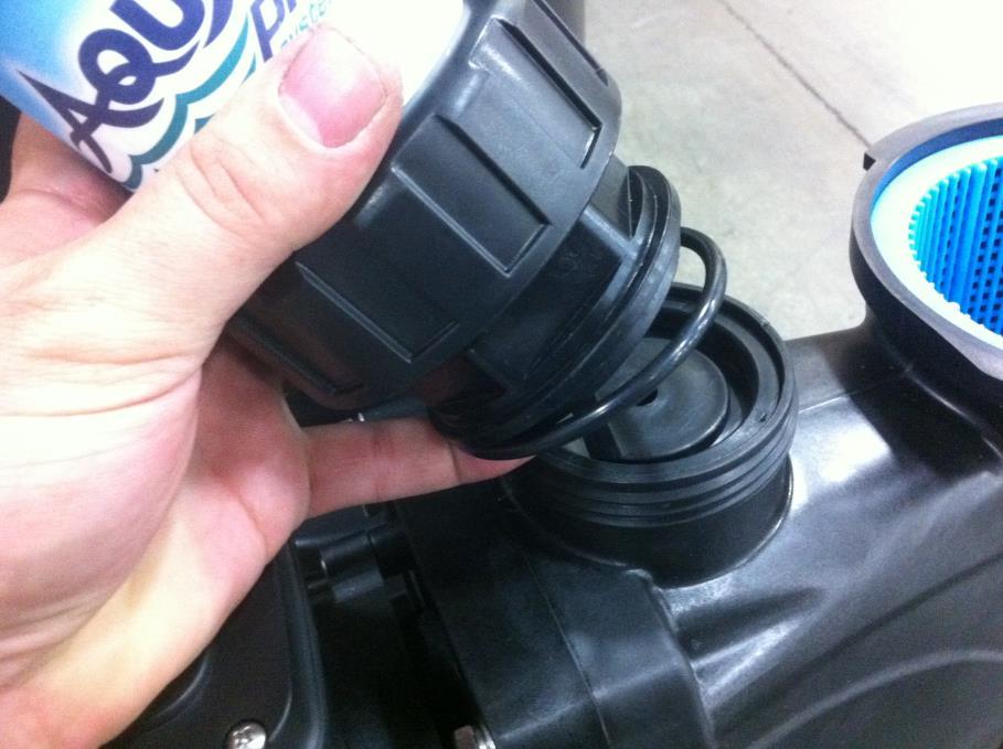
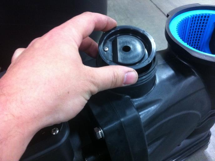
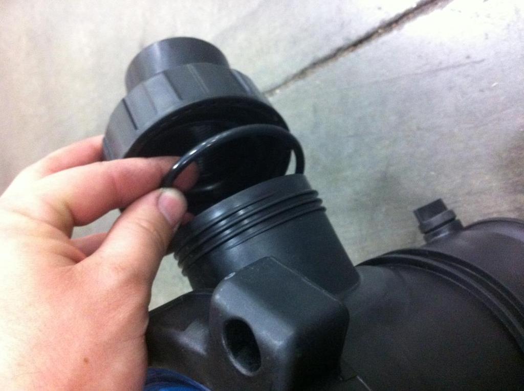
17 A Ground Fault Circuit Interrupter (GFCI) is required in the circuit. For size of GFCI required and test procedures for GFCI, please see manufacturer s instructions. OPERATION Avoid running the pump dry. Fill the pump with water before starting motor. Before removing the trap cover: 1. STOP PUMP before proceeding. 2. CLOSE GATE VALVES in suction and discharge pipes. 3. RELEASE ALL PRESSURE from pump and piping system. 4. NEVER tighten or loosen clamp while pump is operating! If pump is being pressure tested, be sure pressure has been released before removing trap cover. Do not block pump suction. To do so with body may cause severe or fatal injury. Small children using pool must ALWAYS have close adult supervision. Fire and burn hazard. Motor runs at high temperatures, to reduce the risk of fire, do not allow debris, or foreign matter to collect around the pump motor. Allow the motor to cool prior to handling or performing maintenance. The motor is equipped with an internal thermal protection circuit to guard against overheating. The maximum ambient temperature for the motor operation must not exceed rating on motor model plate. Priming Pump Release all pressure from filter, pump, and piping system; see the filter owner s manual. In a flooded suction system (water source higher than pump), pump will prime automatically during suction and discharge valves are opened. If the pump is located above the normal pool water level, remove ring and cover assembly, and fill basket and pump with water. Clean and inspect o-ring; then reinstall on trap. Replace ring and cover assembly, then rotate clockwise to tighten cover. NOTICE: Tighten ring and cover assembly by hand - do not use tools. Pump priming time will depend on the vertical distance and length of the suction line. The pump is designed to prime at 10 ft or less. If the pump does not prime, make sure that all valves are open, and that the suction pipe is submerged. Verify there are no leaks in the suction lines. Routine Maintenance The only routine maintenance needed is the inspection and cleaning of the trap basket. Debris or trash that collects in the basket will choke off water flow through the pump. Before attempting to clean the basket: A. Stop pump, close valves in suction and discharge, and release pressure from system. Hazardous suction can trap hair or body parts, causing severe injury or death. Do not block suction. B. Remove the ring and cover assembly by turning counterclockwise. If necessary, tap handles gently with a rubber mallet. C. Remove the basket and clean. Inspect holes in basket for blockage. Clean the basket with water and replace in trap. Verify that the basket is oriented correctly in pump housing. D. Clean and inspect lid o-ring; then reinstall the ring and cover assembly
18 E. Prime the pump (see priming instructions). Draining the Pump A. Pump down water level below all inlets to the pool. To avoid dangerous or fatal electrical shock hazard, turn OFF power to the motor before draining pump. B. Remove the basket cover C. Drain the basket housing and pump housing through the drain plugs D. Clean the pump and basket, then replace cover assembly. NOTICE: Tighten trap cover by hand only E. Be sure motor is kept dry and covered. Storage/Winterizing: Explosion hazard. Purging the system with compressed air can cause components to explode, with risk of severe injury or death to anyone nearby. Use only a low pressure (below 5 PSI), high volume blower for purging the pump, filter, or piping. NOTICE: Allowing pump to freeze will damage pump and void warranty! NOTICE: Use only non-toxic antifreeze. Do not use automotive antifreeze. It is highly toxic and may damage plastic components in the system. PUMP SERVICE TROUBLESHOOTING GUIDE Read and understand safety and operating instructions in this manual before doing any work on pump! Only qualified personnel should electrically test the pump motor! FAILURE TO PUMP; REDUCED CAPACITY OR DISCHARGE PRESSURE Suction leaks/lost prime: 1. Pump must be primed. Make sure that pump body and basket body are full of water. See priming instructions. 2. Make sure there are no leaks in suction piping. 3. Make sure suction inlet is well below the water level to prevent pump from sucking air. 4. Pump is designed to prime at a vertical distance of 10 ft or less. Verify suction lift is 10 ft or less. Lower pump closer (vertically) to water source. Clogged Pipe/Trap/Impeller, Worn Impeller: 5. Make sure suction trap is not clogged; if it is, then clean trap and strainer. 6. Make sure the impeller is not clogged 7. Impeller and diffuser may be worn. If so, order replacement parts from Repair Parts List, Pages The pump may be trying to push too high a column of water. If so, a higher head pump is needed. Electrical: 9. Pump may be running too slowly; check voltage at motor terminals and at meter while pump is running. If low, see wiring instructions or consult power company. Check for loose connections. 10. Pump may be too hot. A. Check line voltage; if less than 90% or more than 110% of rated voltage consult a licensed electrician. B. Increase ventilation. C. Reduce ambient temperature. D. Tighten any loose connections
19 MECHANICAL TROUBLES AND NOISE 1. If suction and discharge piping are not adequately supported, pump assembly will be strained. See Installation. 2. Do not mount the pump on a wooden platform! Securely mount on a concrete platform for quietest performance before working on pump or motor
20 Limited Warranty For one (1) year from the date of purchase, manufacturer will repair or replace, at its option, for the original owner any parts of its pumps ( Product ) which are found upon examination to be defective in materials or workmanship. Please call for instructions. Be prepared to provide a receipt, the model number, and serial number when exercising this limited warranty. Purchaser must pay all transportation charges on Products or parts submitted for repair or replacement. All non-warranty service charges are the responsibility of the original owner. Failure to pay for non-warranty service charges will void this Limited Warranty. This Limited Warranty does not cover Products that have been damaged as a result of accident, freezing, abuse, misuse, neglect, improper installation, improper maintenance or failure to operate in accordance with written instructions. All maintenance and service must be performed by approved service agents. Any unauthorized alteration or repairs will void this Limited Warranty. THERE IS NO OTHER EXPRESS WARRANTY. IMPLIED WARRANTIES, INCLUDING THOSE OF MERCHANTABILITY AND FITNESS FOR A PARTICULAR PURPOSE, ARE LIMITED TO ONE (1) YEAR FROM THE DATE OF PURCHASE. THIS IS THE EXCLUSIVE REMEDY AND ANY LIABILITY FOR ANY AND ALL INDIRECT OR CONSEQUENTIAL DAMAGES OR EXPENSES WHATSOEVER IS EXCLUDED. Some states do not allow limitations on how long an implied warranty lasts, or do not allow the exclusions or limitations of incidental or consequential damages, so the above limitations might not apply to you. This limited warranty gives you specific legal rights, and you may also have other legal rights which vary from state to state. In no event, whether as a result of breach of contract warranty, tort (including negligence) or otherwise, shall its suppliers be liable for any special, consequential, incidental or penal damages including, but not limited to loss of profit or revenues, loss of use of the products or any associated equipment, damage to associated equipment, cost of capital, cost of substitute products, facilities, services or replacement power, downtime costs, or claims of buyer s customers for such damages. This Limited Warranty does not include freight charges for equipment or component parts, to and from the factory, services such as maintenance or inspection, repair or damage due to negligence such as freezing conditions, incorrect installation, nor acts of God. The liability shall not exceed the repair or replacement of defective parts under this Limited Warranty. This Limited Warranty also does not include unnecessary service calls due to erroneous operational reports,or electrical service. If a non-warranty service call is made, and the homeowner is unwilling to pay for the service call, this Limited Warranty will be voided. This Limited Warranty is voided if the product is repaired or altered by any persons or agencies other than those authorized. This Limited warranty applies only within the continental USA. For warranty outside the continental USA please contact Aquapro Systems customer service. You MUST retain your purchase receipt along with this form. In the event you need to exercise a warranty claim, you MUST present a copy of the purchase receipt at the time of service. Please call for service or return authorization and instructions. DO NOT MAIL THIS FORM. Use this form only to maintain your records. MODEL NO. SERIAL NO. INSTALLATION DATE 8 - -

21 GETTING STARTED: Open Box
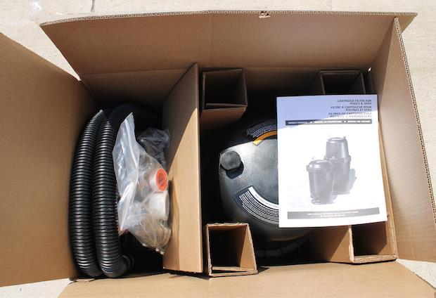
22 Contents
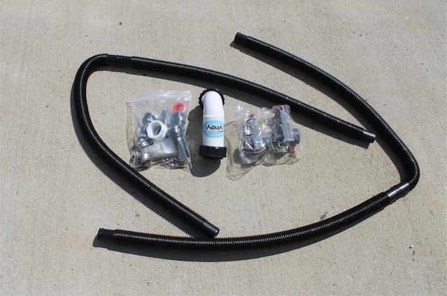
23 Contents
24 Contents

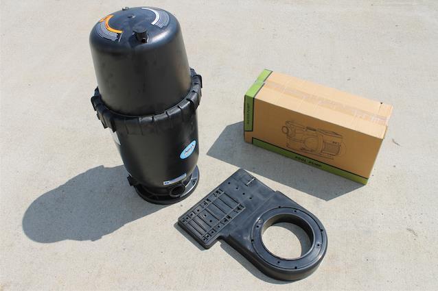
25 Use box to support unit during configuration. Dry fit components to check placement. Place bolts into holes to secure pump base

26 Up-close view of bolt location for pump base.

27 Place on side to access bolts & tighten nuts.


28 Location of bolt on pump base

29 Tighten nuts (located underneath base).

30 Dry fit again, to assure best placement of cartridge.

31 Dry fit again, to assure best placement of cartridge (cont.)

32 Insert bolts into base of cartridge, and line up with base.

33 Close-up view of bolt location on cartridge base.

34 Move unit over edge of box, to allow easy access to underneath base.

35 Tighten nuts to bolts, on underneath side of base.
36 Completely tighten all connectors.

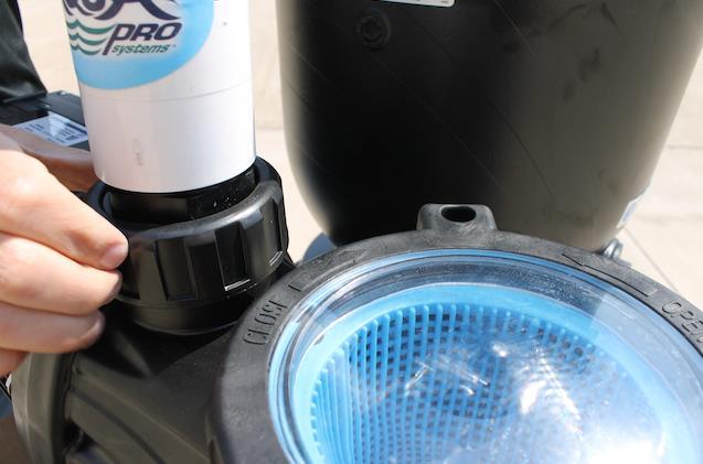
37 Remove bag from inside pump.

38 Tighten end connector.


39 Tighten end connector #2. TEFLON TAPE INCLUDED FOR A GREAT SEAL
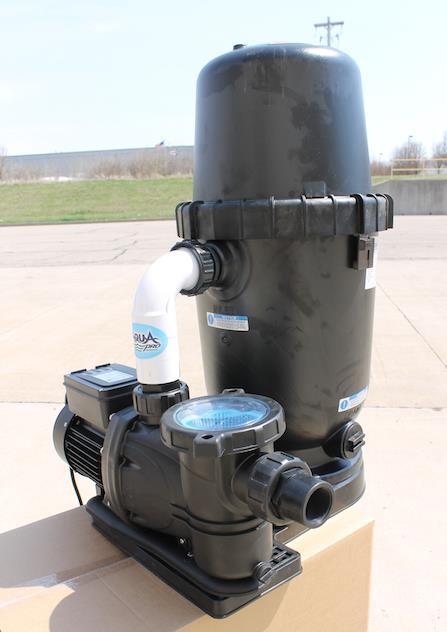
40 Completed configuration.

41 Connect your SYSTEM TO THE POOL WITH PROVIDED HOSES & ACCESSORIES! CALL FOR LIVE HELP! Unit shown with (Optional) shut-off valves
D.E. FILTER FOR POOLS & SPAS FILTRES T.D. POUR PISCINES ET SPAS FILTRO DE D.E. PARA PISCINAS Y TINAS DE HIDROMASAJE
 D.E. FILTER FOR POOLS & SPAS FILTRES T.D. POUR PISCINES ET SPAS FILTRO DE D.E. PARA PISCINAS Y TINAS DE HIDROMASAJE OWNER'S MANUAL MANUEL DU PROPRIÉTAIRE MANUAL DEL USUARIO Certified to NSF/ANSI Standard
59719-XXXX, XXXX, XXXX, XXXX, XXXX and XXXX fax
 CARTRIDGE FILTER FOR POOLS & SPAS Filtre à cartouche pour piscines et spas FILTROS DE CARTUCHO PARA PISCINAS E HIDROMASAJES Owner's manual l MANUEL DU PROPRIÉTAIRE l Manual del usuario 59719-XXXX, 59721-XXXX,
59719-XXXX, XXXX, XXXX, XXXX, XXXX and XXXX fax
 CARTRIDGE FILTER FOR POOLS & SPAS Filtre à cartouche pour piscines et spas FILTROS DE CARTUCHO PARA PISCINAS E HIDROMASAJES Owner's manual l MANUEL DU PROPRIÉTAIRE l Manual del usuario 59719-XXXX, 59721-XXXX,
OWNER S MANUAL D.E. CARTRIDGE. Installation Operation Parts. Models PCDE-30 PCDE-40
 D.E. CARTRIDGE OWNER S MANUAL Installation Operation Parts Models PCDE-30 PCDE-40 2200 East Sturgis Road, Oxnard, CA 93030 Ph. (805) 981-0262 Fax (805) 981-9403 www.waterwayplastics.com waterway@waterwayplastics.com
QUICK START GUIDE OWNER S MANUAL AL50 SERIES SAND FILTRATION TECHNOLOGY PLEASE CALL DO NOT RETURN TO STORE
 QUICK START GUIDE OWNER S MANUAL SAFETY, INSTALLATION, OPERATION & PARTS AL50 SERIES SAND FILTRATION TECHNOLOGY PLEASE CALL 877-278-2797 DO NOT RETURN TO STORE! WARNING This equipment must be installed
CARTRIDGE FILTER SYSTEMS OWNER S MANUAL
 CARTRIDGE FILTER SYSTEMS OWNER S MANUAL Installation Operation Parts Designed, Engineered & Manufactured in the USA. 2017 Waterway Plastics 2200 East Sturgis Road, Oxnard CA 93030 Phone 805.981.0262 Fax
SUNC1200 / ITEM #40882 SUBMERSIBLE UTILITY PUMP OPERATIONS MANUAL
 SUNC1200 / ITEM #40882 SUBMERSIBLE UTILITY PUMP OPERATIONS MANUAL WWW.SUNRUNNERPOOL.COM Performance Model HP GPH of Water @ Total Feet Of Lift 0 ft. 5 ft. 10 ft. 15 ft. 20 ft. 25 ft. Max. Lift SUNC1200
SUNC3000 / Item #40885
 SUNC3000 / Item #40885 AUTOMATIC POOL COVER PUMP OPERATIONS MANUAL WWW.SUNRUNNERPOOL.COM 1 . Performance GPH of Water @ Total Feet Of Lift MODEL HP Max. Lift 0 ft. 5 ft. 10 ft. 15 ft. 20 ft. SUNC3000 1/3
Above Ground Cartridge Filters Models PRC50, 5PRC50, PRC75 and 5PRC75
 INLET Above Ground Cartridge Filters Models PRC50, 5PRC50, PRC75 and 5PRC75 O W N E R S M A N U A L INSTALLATION, OPERATION & PARTS This manual should be furnished to the end user of this filter; its use
Posi Clear TM Cartridge Filters Models PXC75, PXC95, PXC125 and PXC150
 Posi Clear TM Cartridge Filters Models PXC75, PXC95, PXC125 and PXC150 O W N E R S M A N U A L E N G L I S H PUSH PUSH F R A N Ç A I S INSTALLATION, OPERATION & PARTS E S P A Ñ O L This manual should be
OWNER S MANUAL EVOLUTION 3500, 4500, 5500, & 8500 SERIES PUMPS
 OWNER S MANUAL EVOLUTION 3500, 4500, 5500, & 8500 SERIES PUMPS IMPORTANT SAFETY INSTRUCTIONS When installing and using this electrical equipment, basic safety precautions should always be followed, including
OWNER / INSTALLATION MANUAL SAND FILTER SYSTEM
 OWNER / INSTALLATION MANUAL SAND FILTER SYSTEM Questions, problems, missing parts? Before returning to the store, call Customer Service 1-877-278-2797 ECOAQUAPRO.COM THANK YOU We appreciate the trust and
IMPORTANT SAFETY INSTRUCTIONS
 OWNER S MANUAL FLO-MASTER XP2 SERIES PUMPS IMPORTANT SAFETY INSTRUCTIONS When installing and using this electrical equipment, basic safety precautions should always be followed, including the following:
HALLMARK INDUSTRIES INC
 Performance Part No. HP. CONVERTIBLE JET PUMP USER S MANUAL GPH of Water @ Total Discharge Pressure of 40 psi Max. Pressure Max suction (shallow well) Max Suction (deep well) Max GPM (@0 head) Max Discharge
GARDEN HOSE UTILITY PUMP
 GARDEN HOSE UTILITY PUMP MODEL #HPP360, HPP12V, 473707 MODEL #HPP360, 473707 MODEL #HPP12V ATTACH YOUR RECEIPT HERE Purchase Date SAFETY INFORMATION Please read and understand this entire manual before
2-Speed Pumps Item #s 7813, 7814, 7818 & 7819
 2-Speed Pumps Item #s 7813, 7814, 7818 & 7819 INSTALLATION, OPERATION & PARTS In-ground 2-Speed Pumps Item #s 7818 & 7819 Above Ground 2-Speed Pumps Item #s 7813 & 7814 To prevent potential injury and
OWNER S MANUAL SELF-PRIMING PORTABLE UTILITY PUMP
 Model 54011-0 OWNER S MANUAL SELF-PRIMING PORTABLE UTILITY PUMP Questions, problems, missing parts? Before returning to the store call AQUAPRO Customer Service 8 a.m. - 5 p.m., EST, Monday-Friday 1-844-242-2475
ESE Series Cast Iron Sewage Pumps
 Owner s Manual ESE Series Cast Iron Sewage Pumps TABLE OF CONTENTS General Safety.................... 2 Specifications..................... 3 Installation.................... 4 & 5 Troubleshooting...................
Davey Repair or Replacement Guarantee
 Davey Repair or Replacement Guarantee In the unlikely event in Australia or New Zealand that this Davey product develops any malfunction within warranty periods beginning from the date of original purchase
Pressurized Bead Filters
 Pressurized Bead Filters Installation Instructions Table of Contents Safety Information Installation Assembly Start Up Maintenance Troubleshooting Warranty Safety Information: 1. Installation should be
PEDESTAL SUMP PUMP. MODEL # Español p. 11. Zoeller is a registered trademark of Zoeller Co. All Rights Reserved.
 PEDESTAL SUMP PUMP Zoeller is a registered trademark of Zoeller Co. All Rights Reserved. MODEL #1084-0001 Español p. 11 ATTACH YOUR RECEIPT HERE Serial Number Purchase Date Questions, problems, missing
Installation and Operation Manual. Jandy Single Element Cartridge Pool and Spa Filters. CS Series Filters
 H0285700D Installation and Operation Data Installation and Operation Manual Jandy Single Element Cartridge Pool and Spa Filters CS Series Filters FOR YOUR SAFETY - This product must be installed and serviced
Voltmaster Centrifugal Trash Pumps
 Voltmaster Centrifugal Trash Pumps Model TSP2, TSP3 and TSP4 Owner s Manual February 2011 Table of Contents 1 Introduction............................ 1 1.1 Read before using..................... 1 1.2
StormPro BA Series Sump Pump
 Page 1 of 8 Marks & Meanings DANGER: Keep the pump equipment out of the reach of children! Warns that the failure to follow the directions given could cause serious risk to individuals or objects. WARNING:
THERE IS NO OTHER EXPRESS WARRANTY.
 Operating Instructions and Parts Manual Limited Warranty For one year from the date of purchase, Wayne Water Systems ( Wayne ) will repair or re place, at its option, for the original purchaser any part
SUBMERSIBLE SUMP PUMPS
 SUBMERSIBLE SUMP PUMPS Zoeller is a registered trademark of Zoeller Co. All Rights Reserved. MODELS #1073-0001, 1075-0001 Español p. 9 ATTACH YOUR RECEIPT HERE Serial Number Purchase Date Questions, problems,
PRE-PLUMBED SEWAGE SYSTEM
 PRE-PLUMBED SEWAGE SYSTEM Zoeller is a registered trademark of Zoeller Co. All Rights Reserved. MODEL #1910-0009 Español p. 13 ATTACH YOUR RECEIPT HERE Serial Number Purchase Date Questions, problems,
UNPACKING SAFETY GUIDELINES GENERAL SAFETY INFORMATION. Operating Instructions & Maintenance Manual
 Please read and save this Repair Parts Manual. Read this manual and the General Operating Instructions carefully before attempting to assemble, install, operate or maintain the product described. Protect
SHALLOW WELL JET PUMP
 SHALLOW WELL JET PUMP MODEL FJ05S 1/2 HP flintandwalling.com ATTACH YOUR RECEIPT HERE Serial Number Purchase Date 1 FW1642 B TABLE OF CONTENTS Product Specifications...2 Safety Information...2 Package
UNPACKING SAFETY GUIDELINES GENERAL SAFETY INFORMATION. Operating Instructions & Maintenance Manual
 Please read and save this Repair Parts Manual. Read this manual and the General Operating Instructions carefully before attempting to assemble, install, operate or maintain the product described. Protect
PRESSURIZED DIATOMACEOUS EARTH FILTER SYSTEM
 PRESSURIZED DIATOMACEOUS EARTH FILTER SYSTEM This filter system is designed for use with aboveground and semi-inground swimming pools. DO NOT operate this filter system without adding D.E. as it will cause
Installation and Operation Manual Stealth Series Pumps (Models JHP & JHPU) WARNING
 WARNING") H0557700A Installation and Operation Manual Stealth Series Pumps (Models JHP & JHPU) WARNING FOR YOUR SAFETY: This product must be installed and serviced by a professional service technician, qualified
H0557700A Installation and Operation Manual Stealth Series Pumps (Models JHP & JHPU) WARNING FOR YOUR SAFETY: This product must be installed and serviced by a professional service technician, qualified
Aqua Ultraviolet Sunami Series Pumps 1/3HP, 3/4HP, 3HP, 4HP, 5HP
 TM 42371 Avenida Alvarado Temecula, CA 92590 TOLL FREE (800) 454-2725 TEL (951) 296-3480 FAX (951) 296-3490 www.aquauv.com Aqua Ultraviolet Sunami Series Pumps 1/3HP, 3/4HP, 3HP, 4HP, 5HP Sunami Warranty
AUTOMATIC SUBMERSIBLE UTILITY PUMP
 AUTOMATIC SUBMERSIBLE UTILITY PUMP Zoeller is a registered trademark of Zoeller Co. All Rights Reserved. MODEL #1043-0006 Español p. 9 ATTACH YOUR RECEIPT HERE Serial Number Purchase Date Questions, problems,
SEWAGE PUMP MODEL # Zoeller is a registered trademark of Zoeller Co. All Rights Reserved. Español p. 14
 SEWAGE PUMP Zoeller is a registered trademark of Zoeller Co. All Rights Reserved. MODEL #1261-0001 Español p. 14 ATTACH YOUR RECEIPT HERE Serial Number Purchase Date Questions, problems, missing parts?
STAR STOP SHALLOW WELL JET PUMP
 SHALLOW WELL JET PUMP MODEL SJ0S / HP STAR starwatersystems.com STOP Questions, problems, missing parts? Before returning to your retailer, call our customer service department at -800-7-0, 7:0 a.m. -
Installation Manual DIAPHRAGM WELL TANK
 Installation Manual DIAPHRAGM WELL TANK IN-LINE SERIES: 2-5 & 7 GALLON VERTICAL SERIES: 14-20-25-32-36-52-65-86-96-119 GALLON HORIZONTAL SERIES: 7-14 & 20 GALLON NO LEAD NO LEAD: The weighted average of
GRINDER PUMP MODEL # Zoeller is a registered trademark of Zoeller Co. All Rights Reserved. Español p. 13
 GRINDER PUMP Zoeller is a registered trademark of Zoeller Co. All Rights Reserved. MODEL #2701-0005 Español p. 13 ATTACH YOUR RECEIPT HERE Serial Number Purchase Date Questions, problems, missing parts?
STOP CITY PRESSURE BOOSTER PUMP INSTRUCTION MANUAL
 CITY PRESSURE BOOSTER PUMP INSTRUCTION MANUAL MODEL #VP05, VP10 C US NSF/ANSI 372 255405 For loose, missing or damaged parts, or if the unit does not seem to be operating properly, please call before returning
SUBMERSIBLE SUMP PUMPS
 SUBMERSIBLE SUMP PUMPS Zoeller is a registered trademark of Zoeller Co. All Rights Reserved. MODEL #1099-0001 Español p. 11 ATTACH YOUR RECEIPT HERE Serial Number Purchase Date Questions, problems, missing
READ THIS MANUAL CAREFULLY BEFORE USING THE PUMP
 OWNER S MANUAL Pond Pump READ THIS MANUAL CAREFULLY BEFORE USING THE PUMP Important Notice: This manual contains important information about the installation, operation and safe use of this product. This
READ THIS MANUAL CAREFULLY BEFORE USING THE PUMP
 OWNER S MANUAL Swimming Pool Pump READ THIS MANUAL CAREFULLY BEFORE USING THE PUMP Important Notice: This manual contains important information about the installation, operation and safe use of this product.
6 and 8 HAIR AND LINT STRAINERS
 6 and 8 HAIR AND LINT STRAINERS O W N E R S M A N U A L INSTALLATION, OPERATION & PARTS MODELS Pkg. 51 6 Cast Iron Pkg. 98 8 Cast Iron Pkg. 56 6 Bronze Pkg. 99 8 Bronze This manual should be furnished
INSTALLATION & OPERATING INSTRUCTIONS
 INSTALLATION & OPERATING INSTRUCTIONS WARNING RISK OF ELECTRIC SHOCK. CONNECT ONLY TO A CIRCUIT PROTECTED BY A GROUND-FAULT CIRCUIT-INTERRUPTER. THE UNIT SHOULD BE INSTALLED BY A QUALIFIED SERVICE REPRESENTATIVE.
OWNER S MANUAL Spa & Jetted Bathtub Pump
 OWNER S MANUAL Spa & Jetted Bathtub Pump READ THIS MANUAL CAREFULLY BEFORE USING THE SPECK PUMP Important Notice: This manual contains important information about the installation, operation and safe use
SUBMERSIBLE SWIMMING POOL DRAINER
 SUBMERSIBLE SWIMMING POOL DRAINER O W N E R S M A N U A L INSTALLATION, OPERATION & PARTS MODEL PCD-10B Sta-Rite Pool/Spa Group 293 Wright Street, Delavan, WI 53115 Use of electrical appliances around
END SUCTION CENTRIFUGAL PUMPS
 OWNERS GUIDE TO INSTALLATION AND OPERATION FW000 009 Supersedes 07 END SUCTION CENTRIFUGAL PUMPS READ THESE INSTRUCTIONS CAREFULLY Read these installation instructions in detail before installing your
Owners Manual: - Pumps
 Owners Manual: - Pumps GENERAL SAFETY RULES 1. The products mentioned in this manual are specially designed for the pre-filtering and re-circulation of water in swimming pools and spas. 2. They are designed
OWNER S MANUAL SUBMERSIBLE UTILITY PUMP
 Model 51101-0 OWNER S MANUAL SUBMERSIBLE UTILITY PUMP Questions, problems, missing parts? Before returning to the store call AQUAPRO Customer Service 8 a.m. - 5 p.m., EST, Monday-Friday 1-844-242-2475
Matala. VersiFlow Series. Instruction and Maintenance Manual
 VersiFlow Series High Flow Multi-Purpose "Versatile " Pump V-3200 1/5HP 150W / Discharge 2 V-3900 1/3HP 250W / Discharge 2 V-4700 1/2HP 400W / Discharge 2 V-5600 1HP 750W / Discharge 2 Instruction and
STOP. Oil Pump Models L 5016, L 5116 & L Owner s Manual DO NOT RETURN THIS PRODUCT TO THE STORE! SAVE THESE INSTRUCTIONS TABLE OF CONTENTS
 SAVE THESE INSTRUCTIONS 5252 East 36th Street North Wichita, KS USA 67220-3205 TEL: 316-686-7361 FAX: 316-686-6746 Oil Pump Models L 5016, L 5116 & L 5132 Owner s Manual STOP DO NOT RETURN THIS PRODUCT
Oil Pump Models L 5016, L 5116 & L 5132
 SAVE THIS OWNER S MANUAL Oil Pump Models L 5016, L 5116 & L 5132 Owner s Manual DO NOT RETURN THIS PRODUCT TO THE STORE! Please contact GPI before returning any product. If you are missing parts or experience
ProFlo FatBoy
 The Standard For Professional Grade Diaphragm Pumps. ProFlo 3300 5500 FatBoy Operational and Installation Guidelines, Repair & Parts Contents 3300 5500 Fatboy Operational and Installation Guidelines...2
Artesian2 Owners Manual
 Artesian2 Owners Manual Energy-Efficient, Self Priming Centrifugal Pumps Discharge Inlet Important Safety Instructions Please read all instructions completely before you install or operate your new pump.
READ THIS MANUAL CAREFULLY BEFORE USING THE SPECK PUMP
 OWNER S MANUAL Spa & Jetted Bathtub Pump READ THIS MANUAL CAREFULLY BEFORE USING THE SPECK PUMP Important Notice: This manual contains important information about the installation, operation and safe use
LAWN SPRINKLER, IRRIGATION PUMP
 LAWN SPRINKLER, IRRIGATION PUMP MODEL #, SP0P, SP5P, SP20P, EL0P, EL5P, EL20P SAFETY INFORMATION Please read and understand this entire manual before attempting to assemble, operate or install the product.
HAYWARD POOL PRODUCTS, INC. Corporate Headquarters:
 ISCC100 Rev. D OWNER S MANUAL INSTALLATION, OPERATION, & PARTS XStream Filtration Series The Hayward XStream Filtration Series is specifically designed for the demanding requirements of today s above-ground
Installation, Operation and Maintenance Manual
 IOM-HS-QTColdBevMax Installation, Operation and Maintenance Manual QT TM Cold Bev Max TM Models: QTCLDBMX-1S-.5M, QTCLDBMX-2S-.5M, QTCLDBMX-3S-.5M, QTCLDBMX-4S-.5M, QTCLDBMX-5S-.5M Tested and Certified
OWNER S MANUAL. 6. If you aren t competent to instal the pump, get help from a qualified source.
 OWNER S MANUAL RK2 Systems Pro Pump Energy-Efficient, Self Priming Centrifugal Pumps Important Safety Instructions Please read all instructions completely before you install or operate your new pump. Save
Full Flow Drinking Water System Model: 3MFF100
 Installation and Operating Instructions For Full Flow Drinking Water System Model: 3MFF100 System tested and Certified by NSF International against NSF/ANSI Standard 42 and 53 for the reduction of the
M-3025CB-AV Fuel Pump
 SAVE THESE INSTRUCTIONS M-3025CB-AV Fuel Pump Owner s Manual TABLE OF CONTENTS General Information... 2 Safety Instructions... 2 Installation... 3 Operation... 4 Maintenance... 4 Repair... 5 Troubleshooting...
3 FT CORD UL/NEC Models , , , FT CORD w/gfci UL Models , , ,
 POWERLINE XP I Swimming Pool Pump (Light Oak color model) 3 FT CORD UL/NEC Models 0-1295-206, 0-1296-206, 0-1297-206, 0-1298-206 25 FT CORD w/gfci UL Models 0-1295-200, 0-1296-200, 0-1297-200, 0-1298-200
1600 PSI ELECTRIC PRESSURE WASHER
 MODEL NO.: XE03 SKU: 39-8508-6 1600 PSI ELECTRIC PRESSURE WASHER Owner s Manual QUESTIONS, PROBLEMS, MISSING PARTS? Before returning to your retailer, visit our web site or call our customer service at
QL 420 / 540 CARTRIDGE FILTER
 INSTALLATION AND OPERATING INSTRUCTIONS I INSTALLATION AND OPERATING INSTRUCTIONS NSTAL INSTALLATION AND I QL 420 / 540 CARTRIDGE FILTER 1 IMPORTANT SAFETY PRECAUTIONS ATTENTION INSTALLER: This guide contains
SUBMERSIBLE MINI-PUMP
 SUBMERSIBLE MINI-PUMP Model 41287 Set up And Operating Instructions Diagrams within this manual may not be drawn proportionally. Due to continuing improvements, actual product may differ slightly from
Scale Feeder Manifold Water Filtration System Instruction Manual
 3M TM Water Filtration Products Scale Feeder Manifold Water Filtration System Instruction Manual For SF1XX High Flow Series Water Filtration Systems Installer: Please leave this manual with owner/operator.
RipTide. Brewing Pump. Assembly, Operation, & Maintenance
 RipTide Brewing Pump Assembly, Operation, & Maintenance Congratulations on your purchase, and thank you for selecting the RipTide brewing pump from Blichmann Engineering. We are confident that it will
TP300 INDUSTRIAL TRASH PUMP OPERATOR S MANUAL
 TP300 INDUSTRIAL TRASH PUMP OPERATOR S MANUAL IT IS EXTREMELY IMPORTANT TO READ AND UNDERSTAND THE ENTIRE CONTENTS OF THIS OPERATOR S MANUAL BEFORE ATTEMPTING TO OPERATE THE PRODUCT. THIS EQUIPMENT IS
UNPACKING SAFETY GUIDELINES GENERAL SAFETY INFORMATION. Operating Instructions & Maintenance Manual
 Please read and save this Repair Parts Manual. Read this manual and the General Operating Instructions carefully before attempting to assemble, install, operate or maintain the product described. Protect
Dual Flow Manifold Systems Instruction Manual
 3M TM Water Filtration Products Dual Flow Manifold Systems Instruction Manual For DF1XX and DF2XX High Flow Series manifolds and water filtration systems Installer: Please leave this manual with owner/operator.
3 FT CORD Models , , , FT CORD W/GFCI Models , , ,
 POWERLINE XP II Swimming Pool Pump (Light Oak color model) With Automatic Timer 3 FT CORD Models 0-1395-226, 0-1396-226, 0-1397-226, 0-1398-226 25 FT CORD W/GFCI Models 0-1395-220, 0-1396-220, 0-1397-220,
INSTALLATION INSTRUCTIONS
 INSTALLATION INSTRUCTIONS Universal Air Series!! NOTE!! Covers the following model: 6000 Series 85-0100B-AZ Rev 0 5/07 To ensure that the system is installed properly, provide your electrician with these
INSTALLATION INSTRUCTIONS
 INSTALLATION INSTRUCTIONS Universal Air Series!! NOTE!! Covers the following models: 9000 Series 6000 Series To ensure that the system is installed properly, provide your electrician with these instructions.
Owner s Manual GLASSLINED PUMP TANK
 Owner s Manual GLASSLINED PUMP TANK ANSI/NSF 61 Annex G Thank You for purchasing a pump tank. Properly installed and maintained, it should give you years of trouble free service. If you should decide that
4" ENVIRONMENTAL E-SERIES PUMPS OWNER'S MANUAL. DANGER warns about hazards that will cause. WARNING warns about hazards that can cause
 4" ENVIRONMENTAL E-SERIES PUMPS OWNER'S MANUAL BEFORE INSTALLING PUMP, BE SURE TO READ THIS OWNER S MANUAL CAREFULLY. CAUTION Fill pump with water before starting or pump will be damaged. The motor on
Installation and Operation Manual. Jandy Cartridge Pool/Spa Filters. Models CJ200 and CJ250
 H0556400C Installation and Operation Data Installation and Operation Manual Jandy Cartridge Pool/Spa Filters Models CJ200 and CJ250 FOR YOUR SAFETY - This product must be installed and serviced by a pro
APCO ASR-400/450 SEWAGE AIR RELEASE VALVES
 APCO ASR-400/450 SEWAGE AIR RELEASE VALVES Instruction D12005 December 2012 Instructions These instructions provide installation, operation and maintenance information for the APCO ASR- 400/450 Sewage
25 GALLON PORTABLE OIL LIFT
 25 GALLON PORTABLE OIL LIFT Model 92859 SET UP AND OPERATING INSTRUCTIONS Diagrams within this manual may not be drawn proportionally. Due to continuing improvements, actual product may differ slightly
SPECIFICATIONS Horsepower: 1.5 HP Running Maximum PSI: 125 PSI Tank Capacity: 15 Gallons CFM: 6 40 PSI 5 90 PSI
 15 GALLON AIR COMPRESSOR Model: 7678 DO NOT RETURN TO STORE Please call 800-348-5004 for parts and service CALIFORNIA PROPOSITION 65 WARNING: You can create dust when you cut, sand, drill or grind materials
Air Operated Diaphragm Pumps Operating and Maintenance Instructions
 Product & Chemical Disclaimer The user must take responsibility in the selection of the products materials of construction. Empire Pumps Ltd will act in an advisory role and offer recommendations; however,
GLOBE FLOWCELL. Operating Manual. Rola-Chem Flowcell PN /01/2013 page: 1 of 8
 GLOBE FLOWCELL Operating Manual Rola-Chem Flowcell PN 550182 4/01/2013 page: 1 of 8 Table of Contents Section title Page 1.0 Safety Instructions 2 2.0 Description 2 3.0 Installation 3 4.0 Use of Manifold
Artesian Owners Manual
 Artesian Owners Manual Energy-Efficient, Self Priming Centrifugal Pumps Discharge Inlet Important Safety Instructions Please read all instructions completely before you install or operate your new pump.
StormPro BCV400 Sewage Ejector Pump
 Page 1 of 8 Marks & Meanings DANGER: Keep the pump equipment out of the reach of children! Warns that the failure to follow the directions given could cause serious risk to individuals or objects. WARNING:
GeyserMax-Flow Series
 GeyserMax-Flow Series 115V/60Hz Waterfall Pump GM-3900 1/5HP 150W / Discharge 1-1/2 GM-4700 1/3HP 250W / Discharge 2 GM-5400 1/2HP 400W / Discharge 2 GM-6200 3/4HP 750W / Discharge 2 230V/50Hz GM-3800
Installation and Service Manual for SRC25, SRC252, SRC50, SRC502, SRC75, SRC752
 Rocking Piston Compressors Installation and Service Manual for SRC25, SRC252, SRC50, SRC502, SRC75, SRC752 Thank you for purchasing the Stratus SRC series rocking piston compressor. This instruction manual
OWNER S MANUAL Swimming Pool and Spa Pump
 OWNER S MANUAL Swimming Pool and Spa Pump READ THIS MANUAL CAREFULLY BEFORE USING THE SPECK PUMP Important Notice: This manual contains important information about the installation, operation and safe
DeZURIK 2 20" BOS BUTTERFLY VALVES
 2 20" BOS BUTTERFLY VALVES Instruction D10459 October 2013 2-20 BOS Butterfly Valves Instructions These instructions provide information about BOS Butterfly Valves. They are for use by personnel who are
STEP-BY-STEP INSTALLATION GUIDE
 Battery Backup System STEP-BY-STEP INSTALLATION GUIDE Operating Instructions & Parts Manual ESP25 Please read and save these instructions. Read carefully before attempting to assemble, install, operate
INSTALLATION AND OPERATING INSTRUCTIONS
 INSTALLATION AND OPERATING INSTRUCTIONS I INSTALLATION AND OPERATING INSTRUCTIONS Hurlcon Pumps CTX Series, E Series BX Series & FX Series Bolero ND Cleaner INSTALLATION AND OPERATING INSTRUCTIONS Melbourne:
APCO CRF-100A RUBBER FLAPPER SWING CHECK VALVES
 APCO CRF-100A RUBBER FLAPPER SWING CHECK VALVES Instruction D12043 June 2016 DeZURIK Instructions These instructions provide installation, operation and maintenance information for APCO CRF-100A Rubber
ArtesianPro Owners Manual
 ArtesianPro Owners Manual Energy-Efficient, Self Priming Centrifugal Pumps Discharge Inlet Important Safety Instructions Please read all instructions completely before you install or operate your new pump.
UNPACKING SAFETY GUIDELINES GENERAL SAFETY INFORMATION. Operating Instructions & Maintenance Manual
 Please read and save this Repair Parts Manual. Read this manual and the General Operating Instructions carefully before attempting to assemble, install, operate or maintain the product described. Protect
Pantera Cartridge Filter II PCF-II
 OWNER S MANUAL Pantera Cartridge Filter II PCF-II Should the installer or owner be unfamiliar with the correct installation or operation of this type of equipment you should contact the distributor/manufacturer
Marlow Series Cast Iron Swimming Pool Pumps
 INSTRUCTION MANUAL SECTION 360A AC1683 REVISION C INSTALLER: PLEASE LEAVE THIS MANUAL FOR THE OWNER'S USE. Marlow Series Cast Iron Swimming Pool Pumps 3B28EC 3B32EC PLEASE FILL IN DATA FROM YOUR PUMP NAMEPLATE
FP0S2300X FP0S3000X. Submersible Waterfall/Utility Pumps OWNER S MANUAL. Call Installation/Operation/Parts. English...
 P.O. Box 342, Delavan, WI 53115 Phone: 1-800-365-6832 Fax: 1-800-526-3757 E-Mail: info@flotecwater.com Web Site: http://www.flotecwater.com OWNER S MANUAL Submersible Waterfall/Utility Pumps 3384 0399
M-1115S Series Fuel Pump
 SAVE THESE INSTRUCTIONS M-1115S Series Fuel Pump Owner s Manual TABLE OF CONTENTS General Information...2 Safety Instructions...2 Installation...3 Operation...4 Maintenance...5 Repair...5 Troubleshooting...9
Installation, Operation and Maintenance Manual
 IOM-HS-QTCubeMax Installation, Operation and Maintenance Manual QT TM Cube Max TM Models: QTCBMX-1S-1M, QTCBMX-2S-1M, QTCBMX-3S-1M, QTCBMX-4S-1M, QTCBMX-1L-1M, QTCBMX-2L-1M, QTCBMX-3L-1M, QTCBMX-4L-1M,
Value Super Filter Max Installation Manual
 Value Super Filter Max Installation Manual Barrie, Ontario, Canada, L4N 4Y8 www.excaliburwater.com EXCALIBUR VALUE SUPER FILTER MAX INSTALLATION MANUAL INSTALLATION PROCEDURES: The Value Super Filter Max
S T O P. Oil Pump. Models L 5016, L 5116 and L Owner s Manual DO NOT RETURN THIS PRODUCT TO THE STORE! SAVE THESE INSTRUCTIONS TABLE OF CONTENTS
 SAVE THESE INSTRUCTIONS Oil Pump Models L 5016, L 5116 and L 5132 Owner s Manual 5252 East 36th Street North Wichita, KS USA 67220-3205 TEL: 316-686-7361 FAX: 316-686-6746 A Great Plains Ventures Subsidiary
MODEL CJ-200E CoilJet Portable HVAC Coil Cleaning System
 MODEL CJ-200E CoilJet Portable HVAC Coil Cleaning System OPERATING AND MAINTENANCE INSTRUCTIONS 404 West Avenue Stamford, CT 06902 (888)700-3540 www.speedclean.com COILJET is a registered trademark of