INSTALLATION MANUAL STK-1003B & STK Suction Tube Kit Dodge Cummins Ford Powerstroke GM Duramax
|
|
|
- Beverly Hoover
- 6 years ago
- Views:
Transcription


1 INSTALLATION MANUAL STK-1003B & STK-1003 Suction Tube Kit Dodge Cummins Ford Powerstroke GM Duramax
2 Dear Valued Customer, Made in the USA is not just a slogan at FASS; it s what we live by! FASS is not only assembled in the USA but 98%+ of the FASS product is manufactured in the USA, helping to employ Americans and strengthen America. At FASS, we scrutinize our suppliers and demand the highest quality American-made components. However, this does come at a price, which is one of the main reasons FASS products are more expensive than the competition. Remember price does not dictate quality but quality does dictate price! Here at FASS, we believe it s worth the commitment and will continue this practice to support America! Our competition is doing exactly the opposite by using foreign-made components. Building extremely High-Quality fuel products is our business. We concentrate all of our efforts in this arena. No one else is as specialized as FASS in what we do! This is one of the ingredients to insure you are running with the Highest-Quality fuel system in the world! We have implemented very rigorous testing procedures to provide the Highest Quality we have become known for. Not only is our product superior, but customer satisfaction is #1 at FASS. It is our goal to provide the best service possible. Our confidence is evident in the products we make as each product is backed by an industry leading warranty! Our R & D department, in conjunction with our Dealer Support department, is continually searching for ways to improve quality, expand our product line, and provide superb support to our network of dealers so our customers needs and expectations will be exceeded. To help insure you receive the proper system and customer support at the local level, FASS has a VIP and Authorized Dealer network representing FASS products. We recommend you go to click Find A Dealer, put in their ZIP code, select the type of dealer, and see if the company you purchased from is listed. If they are not, put their phone number in the field below the ZIP code field to see if they are listed. Below these two fields is a list of Terminated/Unauthorized dealers. You may want to review this list. If the company is not listed or is on the Terminated/ Unauthorized list, we suggest you return the product immediately to that dealer and call FASS. We ll recommend you to the nearest dealer. 2
3 INSTALLATION MANUAL Follow these steps to ensure a simple installation of your new FASS ACCESSORY 1. Read the installation manual completely before attempting installation. The installation of this product indicates that the buyer has read and understands the limitations of the FASS manufacturers warranty agreement and accepts the responsibility of its terms and conditions. 2. Inventory the package components. Notify the place of purchase immediately of any parts missing or damaged. 3. The installation recommendations contained herein are guidelines. Use good judgment and take into consideration your vehicles' accessories, i.e. empty fuel tank before beginning installation of this product. 4. For best results in accuracy and efficiency (due to training, communication, and our relationship with our dealer network), we recommend a ViP FASS Fuel Systems dealer for the installation. They are prepared to install the FASS fuel pumps with the most efficiency. If a situation/problem arises during the installation, they are the most prepared for that situation/problem. DPPI is not responsible for any installation mistakes. 5. If you have any questions or concerns that can not be addressed with your dealer, or call FASS. 6. If any installation procedure is uncertain, contact FASS technical support. techsupport@fassride.com or call customer service;
4 STK-1003B Contents ST-1006P DT-1002 Template TC-1001 HC-1001 Button Head Screw Set Screw 4


5 STK-1003 Contents ST-1006P DT-1002 BHF-1002 Template TC-1001 PL-1001 PL-1004 OR-223 BHN-1001 LW-1001 HC-1001 Button Head Screw Set Screw 1/2 Plug 5


6 Some of the photo s are of a different application, refer to the photos that resemble your application. A. Disconnect the vehicles battery. Remove the filler neck and overflow tubes from the truck by loosening the clamps. Possible Variations Clamps will be located at both ends Clamps will be located at the tank. Some applications have an integrated overflow/inner tube assembly. If so, then make sure the inner tube does not hang-up in the tank. B. Before tank is removed or moved, identify ALL areas of clearance between the tank and the truck s bed for the best location to install the BHF assembly. With proper clearance, you want to install it as close to the Fuel sending unit as possible. C. Disconnect the factory suction and return line. If more space is required to access the top of the fuel tank, loosen the strap nuts to the end of the stud. This will gain you about 3 more working room. Possible Variations Press in on the 2 blue tabs and pull off the black fuel connector. The blue tabs will stay on the factory ports. 1. Pull up on the locking tab (either blue or yellow), 2. Push in slightly on the connector, 3. Press down on the release tab, 4. Pull the connector straight off, Pinch in red tabs, pull out locking collar. You may have use a Fuel Line Disconnect tool and lower the Fuel Cooler to access the Suction line. 6


7 D. Disconnect the factory electrical harness. E. Unbolt the tank and remove it from vehicle. Clean all fittings and save for reinstallation. F. Clean the fuel module area then remove the lock ring/nut. Note/Mark the location of the fuel sending unit in relation the top of the fuel tank fro re-installation. FORD applications will be spring loaded, hold the unit down while removing ring to prevent it from popping up and possibly causing damage. G. Carefully remove fuel sending unit from tank making note of the fuel level arm. Do not bend the arm. H. Clean the inside and outside of the basket with an appropriate cleaner paying attention to the screen (inside and bottom). Make sure the rubber valve discs located on the inside bottom of the basket are functioning properly. 7


 by removing the manifold & by plugging the angled tube of the return manifold")

 & its length, fuel line, fittings,")
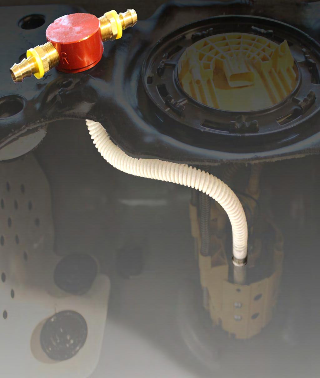
8 This step applies on ly to the STK-1003 A. Installation of the STK-1003B may go directly to step 3. Using thread tape, assemble the appropriate PL fittings (PL-1004 s for 1/2 fuel line or PL-1001 s for 3/8 fuel line) into the BHF-1002 ports labeled S and R. Torque to 40lbs/ft Maintaining FASS Return Fuel to Filler Neck Re-Routing the FASS Return Fuel from the Filler Neck Insert the 1/2 plug into the R port of the BHF-1001 Reroute this line to the R port of the BHF-1002 (bulk head fitting) by removing the manifold & by plugging the angled tube of the return manifold located in your filler neck B. Place the lock ring/nut back on the tank and position the BHF-1002 as close to the fuel sending unit as possible. Keep in mind the appropriate clearances for the convoluted tube (ST-1006P) & its length, fuel line, fittings, and the bottom of the bed support. You may need to trim the fiberglass / plastic shell of the tank for a proper fit. Mark location C. Double check selected area for any interferences with tank straps, bed rails, fuel level arm, etc. Make sure area is clean of all debris. 8


9 D. Drill a 1 1/2 hole where marked, catching all debris by holding a cup under the drilling site. Take any necessary steps to limit tank contamination with debris. E. De-burr hole and check for fit. F. Place the OR-223 over the BHF assembly. Then place the assembly into drilled hole. Remember to place the BHF assembly so that the fuel line (to be connected to the PL fitting) will not be pinched or interfere with the fuel sending unit. G. Secure the assembly by placing the washer (LW-1001) onto the assembly then screwing the nut (BHN- 1001) on from inside of the tank. 9


10 Some of the photo s are of a different application, refer to the photos that resemble your application. A. Using the tube collar (TC-1001) as a guide, find the best location inside the fuel basket for the Draw Tube assembly (DT TC-1001). Use the template located on the contents page to mark the 2 holes on the outside of the basket. Possible Variations Flat side Opposite side of fuel arm lever Dual basket fuel module A1. If working with dual basket fuel module (some Duramax applications ) follow these subsection steps. Using a flat tipped screw driver, carefully remove the outer basket. A2. The factory return line nipple must be pulled or pried off the outer basket without breaking it. The nipple will be reinstalled. A3. Using a flat tipped screw driver, remove the suction tube footing. 10


11 A4. Use a sharp blade to cut the suction tube collar and remove the plastic footing. Discard the footing. A5. Using tool of your choice, remove the marked area on the green inner cup to make room for the TC Do not cut off the locking tab! Measure twice and cut once. When cutting plastic use sharp tools and take your time! B. Drill pilot holes for the draw tube assembly with a 1/16 bit. Use a 1/4 bit for the final hole size. C. De-burr and clean holes as necessary. D. Install the tube collar using the Button Head Screws. E. Insert the draw tube (DT-1002) into the tube collar. Allow the draw tube to bottom out. 11


12 F. Mark the draw tube along the collar. Remove the draw tube assembly from the basket. G. Mark an install line 1/8-3/16 below your 1st mark. Using the set screws and your install line as a guide, install the draw tube into the tube collar. This will allow for the tube to sit above the bottom of the basket and draw fuel. H. Using the button head screws, install the draw tube assembly into the basket If working with the inner basket, must first reinstall the outer basket of the fuel sending unit. Make sure the basket locks onto the tabs of the inner basket. I. Using a Sharpie, mark staggered holes starting 1 from the bottom of the basket. Avoid marking holes where the factory return stacks and posts guides are located as well as where the draw tube assembly is installed. Check to make sure you have proper clearance inside the basket when you mark drill points. You may remove the draw tube only. Leave the tube collar assembled onto the basket. 12


13 J. When drilling through plastic use a gentle touch and let the tool do the work. Do not press hard! Drill pilot holes with a 1/8 bit. Enlarge holes to 3/8 using a larger bit or high speed rotary grinder. Check for shavings and clean up holes. K. De-burr and clean holes as necessary. 13

.")


14 Some of the photo s are of a different application, refer to the photos that resemble your application. A. Attach the ST-1006P to the BHF assembly using the hose clamp (HC- 1001). Allow the tube to hang down for now. You will be grabbing it later during the installation. If installing the STK-1003B, remove the old suction tube from the BHF assembly first. A1. Working with a dual basket fuel module you will need to guide the factory return through the inner cup. Insert nipple into factory stack. B. Carefully begin to install the fuel sending unit keeping in mind the original orientation. Do not bend the fuel sending arm. Reach in the tank and grab the bottom of the ST-1006P and place the remaining hose clamp (HC-1001) onto the end C. Install the suction tube onto the draw tube assembly D. Tighten hose clamp 14


15 E. Make sure there are no restrictions in the ST-1006P F. Compress the fuel sending unit into the tank. Align any marks. Be sure that the fuel level arm and the newly installed suction tube are not obstructed or pinched. G. Reinstall the factory lock ring/nut H. Using oil, push fuel line onto the push lock located at the S port of the BHF assembly. If returning fuel to the BHF assembly attach the FASS fuel return line to the R port of the BHF assembly. NOTE: Hose clamps are not recommended for push lock fittings. They will hold up to 300psi! Use oil on fittings and inside fuel line when installing Push-Lok fittings I. Reconnect the factory suction line or plug it to prevent debris from infiltrating the tank. 15
16 J. Reconnect the factory electrical harness. K. Reconnect the filler neck and overflow tubes from the truck by tightening the clamps Possible Variations Clamps will be located at both ends Clamps will be located at the tank. Some applications have an integrated overflow/inner tube assembly. If so, then make sure the inner tube does not hang-up in the tank. L. Reinstall fuel tank. Torque hanger bolts to factory specifications. If need be, cover the return line with spare tubing or similar to protect fuel line from rubbing on the trimmed fiberglass shell. Route FASS fuel line to prevent pinching. M. Reconnect the vehicles battery. Prime the FASS fuel system. according to owners manual. Note: Secure all fuel lines with cable ties. Cable ties are an economical way to prevent the possibility of problems occurring! 16
INSTALLATION MANUAL STK ACCESSORY: Suction Tube Kit SUMP
 INSTALLATION MANUAL STK-5500 ACCESSORY: Suction Tube Kit SUMP Dear Valued Customer, Made in the USA is not just a slogan at FASS; it s what we live by! FASS is not only assembled in the USA but 98%+ of
INSTALLATION MANUAL STK-5500BO ACCESSORY: Sump Kit
 INSTALLATION MANUAL STK-5500BO ACCESSORY: Sump Kit Dear Valued Customer, Made in the USA is not just a slogan at FASS; it s what we live by! FASS is not only assembled in the USA but 98%+ of the FASS product
INSTALLATION MANUAL AppLIcATION:
 INSTALLATION MANUAL Application: P D07 095G (95gph @ 16psi) P D07 150G (150gph @ 16psi) Cummins 5.9L /6.7L 24 Valve 2005-2012 *1998.5-2004 with In-tank Lift Pump* Dear Valued Customer, Made in the USA
INSTALLATION MANUAL ACCESSORY:
 INSTALLATION MANUAL ACCESSORY: No Drill Bolt on Bracket Kit Dodge Cummins 1989-1993 Ford Powerstroke 1999-2012 Dear Valued Customer, Made in the USA is not just a slogan at FASS; it s what we live by!
INSTALLATION MANUAL ACCESSORY:
 INSTALLATION MANUAL ACCESSORY: No Drill Bolt on Bracket Kit Dodge Cummins 1994-2012 GM Duramax 2001-2012 Dear Valued Customer, Made in the USA is not just a slogan at FASS; it s what we live by! FASS is
INSTALLATION MANUAL SFB-1001 ACCESSORY: SEMI Frame Bracket
 INSTALLATION MANUAL SFB-1001 ACCESSORY: SEMI Frame Bracket Dear Valued Customer, Made in the USA is not just a slogan at FASS; it s what we live by! FASS is not only assembled in the USA but 98%+ of the
INSTALLATION MANUAL APPLICATION: FA D07 095G 16-18psi) FA D07 150G 16-18psi) Cummins 5.9L/6.7L 24 Valve
 FA D07 150G 16-18psi) Cummins 5.9L/6.7L 24 Valve") INSTALLATION MANUAL APPLICATION: FA D07 095G (95GPH @ 16-18psi) FA D07 150G (150GPH @ 16-18psi) Cummins 5.9L/6.7L 24 Valve 2005-2009 *1998.5-2004 with In-tank Pump Modification* **2003-2004 must order
INSTALLATION MANUAL APPLICATION: FA D07 095G (95GPH @ 16-18psi) FA D07 150G (150GPH @ 16-18psi) Cummins 5.9L/6.7L 24 Valve 2005-2009 *1998.5-2004 with In-tank Pump Modification* **2003-2004 must order
INSTALLATION MANUAL. 220 gph (T D08 220G) Cummins 5.9L 24 Valve REVISED 4/05/11
 Cummins 5.9L 24 Valve REVISED 4/05/11") INSTALLATION MANUAL Application: 220 gph (T D08 220G) Cummins 5.9L 24 Valve 1998.5-2004 REVISED 4/05/11 Dear Valued Customer, Made in the USA is not just a slogan at FASS; it s what we live by! FASS is
INSTALLATION MANUAL Application: 220 gph (T D08 220G) Cummins 5.9L 24 Valve 1998.5-2004 REVISED 4/05/11 Dear Valued Customer, Made in the USA is not just a slogan at FASS; it s what we live by! FASS is
INSTALLATION MANUAL. Application: DRP 04 18psi) Dodge Replacement
 Dodge Replacement") INSTALLATION MANUAL Application: DRP 04 (70gph @ 18psi) Dodge Replacement 2003-2004 Dear Valued Customer, Made in the USA is not just a slogan at FASS; it s what we live by! FASS is not only assembled
INSTALLATION MANUAL Application: DRP 04 (70gph @ 18psi) Dodge Replacement 2003-2004 Dear Valued Customer, Made in the USA is not just a slogan at FASS; it s what we live by! FASS is not only assembled
WARNINGs! Read all instructions before starting installation of this product! Installing the improper FASS Pump can cause severe engine damage.
 WARNINGs! Read all instructions before starting installation of this product! Installing the improper FASS Pump can cause severe engine damage. FASS Recommended Application T F17 150G Powerstroke (6.7L)
INSTALLATION MANUAL APPLICATION: T D07 095G 16psi) T D07 150G 16psi) Cummins 5.9L/6.7L 24 Valve
 T D07 150G 16psi) Cummins 5.9L/6.7L 24 Valve") INSTALLATION MANUAL APPLICATION: T D07 095G (95gph @ 16psi) T D07 150G (150gph @ 16psi) Cummins 5.9L/6.7L 24 Valve 2005-2015 1998.5-2004 *with In-tank Lift Pump* **Note: Cab and Chassis may require modifications**
INSTALLATION MANUAL APPLICATION: T D07 095G (95gph @ 16psi) T D07 150G (150gph @ 16psi) Cummins 5.9L/6.7L 24 Valve 2005-2015 1998.5-2004 *with In-tank Lift Pump* **Note: Cab and Chassis may require modifications**
INSTALLATION MANUAL APPLICATION: FA D10 240G 45psi) Cummins 5.9L 12 Valve *With P7100 Injection pump* **bypassing the factory lift pump**
 Cummins 5.9L 12 Valve *With P7100 Injection pump* **bypassing the factory lift pump**") INSTALLATION MANUAL APPLICATION: FA D10 240G (240gph @ 45psi) Cummins 5.9L 12 Valve *With P7100 Injection pump* **bypassing the factory lift pump** 1994-1998 Dear Valued Customer, Made in the USA is not
INSTALLATION MANUAL APPLICATION: FA D10 240G (240gph @ 45psi) Cummins 5.9L 12 Valve *With P7100 Injection pump* **bypassing the factory lift pump** 1994-1998 Dear Valued Customer, Made in the USA is not
INSTALLATION MANUAL APPLICATION: T F16 220G 8-10psi) Powerstroke 6.4L **Note: Cab and Chassis may require modifications**
 Powerstroke 6.4L **Note: Cab and Chassis may require modifications**") INSTALLATION MANUAL APPLICATION: T F16 220G (220GPH @ 8-10psi) Powerstroke 6.4L 2008-2010 **Note: Cab and Chassis may require modifications** Dear Valued Customer, Made in the USA is not just a slogan
INSTALLATION MANUAL APPLICATION: T F16 220G (220GPH @ 8-10psi) Powerstroke 6.4L 2008-2010 **Note: Cab and Chassis may require modifications** Dear Valued Customer, Made in the USA is not just a slogan
INSTALLATION MANUAL APPLICATION: DRP psi) Dodge Replacement
 Dodge Replacement") INSTALLATION MANUAL APPLICATION: DRP 02 (110GPH @ 16-18psi) Dodge Replacement 1998.5-2002 Dear Valued Customer, Made in the USA is not just a slogan at FASS; it s what we live by! FASS is not only assembled
INSTALLATION MANUAL APPLICATION: DRP 02 (110GPH @ 16-18psi) Dodge Replacement 1998.5-2002 Dear Valued Customer, Made in the USA is not just a slogan at FASS; it s what we live by! FASS is not only assembled
INSTALLATION MANUAL APPLICATION: T F14 125G 55psi) Powerstroke 7.3L *Bypassing the Factory Lift Pump*
 Powerstroke 7.3L *Bypassing the Factory Lift Pump*") INSTALLATION MANUAL APPLICATION: T F14 125G (125GPH @ 55psi) Powerstroke 7.3L *Bypassing the Factory Lift Pump* 1999-2003 Powerstroke 6.0L *Bypassing the Factory Lift Pump* 2003-2007 **Note: Cab and Chassis
INSTALLATION MANUAL APPLICATION: T F14 125G (125GPH @ 55psi) Powerstroke 7.3L *Bypassing the Factory Lift Pump* 1999-2003 Powerstroke 6.0L *Bypassing the Factory Lift Pump* 2003-2007 **Note: Cab and Chassis
INSTALLATION MANUAL APPLICATION: DRP psi) Dodge Replacement
 Dodge Replacement") INSTALLATION MANUAL APPLICATION: DRP 04 (110GPH @ 16-18psi) Dodge Replacement 2003-2004 Dear Valued Customer, Made in the USA is not just a slogan at FASS; it s what we live by! FASS is not only assembled
INSTALLATION MANUAL APPLICATION: DRP 04 (110GPH @ 16-18psi) Dodge Replacement 2003-2004 Dear Valued Customer, Made in the USA is not just a slogan at FASS; it s what we live by! FASS is not only assembled
INSTALLATION MANUAL APPLICATION: FA C09 220G 12-14psi) FA C09 260G 12-14psi) Standard Pickup Truck Duramax 2500 &
 FA C09 260G 12-14psi) Standard Pickup Truck Duramax 2500 &") INSTALLATION MANUAL APPLICATION: FA C09 220G (220GPH @ 12-14psi) FA C09 260G (2600GPH @ 12-14psi) Standard Pickup Truck Duramax 2500 & 3500 2001-2014 Revision Date: 10/12/2015 Dear Valued Customer, Made
INSTALLATION MANUAL APPLICATION: FA C09 220G (220GPH @ 12-14psi) FA C09 260G (2600GPH @ 12-14psi) Standard Pickup Truck Duramax 2500 & 3500 2001-2014 Revision Date: 10/12/2015 Dear Valued Customer, Made
INSTALLATION MANUAL STK-5500BO ACCESSORY: Sump Kit
 INSTALLATION MANUAL STK-5500BO ACCESSORY: Sump Kit INSTALLATION MANUAL Follow these steps to ensure a simple installation of your new FASS ACCESSORY 1. Read the installation manual completely before attempting
INSTALLATION MANUAL APPLICATION: D-MAX psi) Duramax Fuel Pump
 Duramax Fuel Pump") INSTALLATION MANUAL APPLICATION: D-MAX 7001 (120GPH @ 8-10psi) Duramax Fuel Pump 2001-2010 Dear Valued Customer, Made in the USA is not just a slogan at FASS; it s what we live by! FASS is not only assembled
INSTALLATION MANUAL APPLICATION: D-MAX 7001 (120GPH @ 8-10psi) Duramax Fuel Pump 2001-2010 Dear Valued Customer, Made in the USA is not just a slogan at FASS; it s what we live by! FASS is not only assembled
INSTALLATION MANUAL APPLICATION: T D07 220G 16-18psi) T D07 260G 16-18psi) Cummins 5.9L /6.7L 24Valve Standard Pickup Truck
 T D07 260G 16-18psi) Cummins 5.9L /6.7L 24Valve Standard Pickup Truck") INSTALLATION MANUAL APPLICATION: T D07 220G (220GPH @ 16-18psi) T D07 260G (260GPH @ 16-18psi) Cummins 5.9L /6.7L 24Valve Standard Pickup Truck 2005-2016 1998.5-2004 *with In-tank Lift Pump* **Note: Cab
INSTALLATION MANUAL APPLICATION: T D07 220G (220GPH @ 16-18psi) T D07 260G (260GPH @ 16-18psi) Cummins 5.9L /6.7L 24Valve Standard Pickup Truck 2005-2016 1998.5-2004 *with In-tank Lift Pump* **Note: Cab
INSTALLATION MANUAL APPLICATION:
 INSTALLATION MANUAL APPLICATION: FA C09 220G (220GPH @ 12-14psi) FA C09 260G (2600GPH @ 12-14psi) Standard Pickup Truck Duramax 2500 & 3500 2001-2014 WARNINGS! Read all instructions before starting installation
INSTALLATION MANUAL APPLICATION: T D10 125G 45psi) Cummins 5.9L 12Valve *with P7100 Injection Pump*
 Cummins 5.9L 12Valve *with P7100 Injection Pump*") INSTALLATION MANUAL APPLICATION: T D10 125G (125GPH @ 45psi) Cummins 5.9L 12Valve *with P7100 Injection Pump* 1994-1998 **Note: Cab and Chassis may require modifications** Dear Valued Customer, Made in
INSTALLATION MANUAL APPLICATION: T D10 125G (125GPH @ 45psi) Cummins 5.9L 12Valve *with P7100 Injection Pump* 1994-1998 **Note: Cab and Chassis may require modifications** Dear Valued Customer, Made in
WARNINGs! Read all instructions before starting installation of this product! Installing the improper FASS Pump can cause severe engine damage.
 WARNINGs! Read all instructions before starting installation of this product! Installing the improper FASS Pump can cause severe engine damage. FASS T C12 095G T C12 150G Recommended Application Duramax
INSTALLATION MANUAL APPLICATION: T C10 095G T C10 150G 8psi) Duramx 2500 &
 Duramx 2500 &") INSTALLATION MANUAL APPLICATION: T C10 095G (95gph @8psi) T C10 150G (150gph @ 8psi) Duramx 2500 & 3500 2006-2010 **Note: Cab and Chassis may require modifications** WARNINGs! Read all instructions before
INSTALLATION MANUAL APPLICATION: T C10 095G (95gph @8psi) T C10 150G (150gph @ 8psi) Duramx 2500 & 3500 2006-2010 **Note: Cab and Chassis may require modifications** WARNINGs! Read all instructions before
INSTALLATION MANUAL APPLICATION: T D02 095G 8-10psi) T D02 150G 8-10psi) Cummins 5.9L 12 Valve *with VE Pump*
 T D02 150G 8-10psi) Cummins 5.9L 12 Valve *with VE Pump*") INSTALLATION MANUAL APPLICATION: T D02 095G (95GPH @ 8-10psi) T D02 150G (150GPH @ 8-10psi) Cummins 5.9L 12 Valve *with VE Pump* 1989-1993 Dear Valued Customer, Made in the USA is not just a slogan at
INSTALLATION MANUAL APPLICATION: T D02 095G (95GPH @ 8-10psi) T D02 150G (150GPH @ 8-10psi) Cummins 5.9L 12 Valve *with VE Pump* 1989-1993 Dear Valued Customer, Made in the USA is not just a slogan at
INSTALLATION MANUAL APPLICATION: T D08 095G 16-18psi) T D08 150G 16-18psi) Cummins 5.9L 24 Valve
 T D08 150G 16-18psi) Cummins 5.9L 24 Valve") INSTALLATION MANUAL APPLICATION: T D08 095G (95GPH @ 16-18psi) T D08 150G (150GPH @ 16-18psi) Cummins 5.9L 24 Valve 1998.5-2004 **Note: Cab and Chassis may require modifications** Dear Valued Customer,
INSTALLATION MANUAL APPLICATION: T D08 095G (95GPH @ 16-18psi) T D08 150G (150GPH @ 16-18psi) Cummins 5.9L 24 Valve 1998.5-2004 **Note: Cab and Chassis may require modifications** Dear Valued Customer,
Limited lifetime Warranty
 T C10 095G or T C10 165G Limited lifetime Warranty Motor No: Manufactured Date: Serial No: Warranty Stipulations: Copy of sales receipt mailed with this form All warranty information, located on the front
Limited lifetime Warranty
 T D07 095G or T D07 165G Limited lifetime Warranty Motor No: Manufactured Date: Serial No: Warranty Stipulations: Copy of sales receipt mailed with this form All warranty information, located on the front
INSTALLATION MANUAL APPLICATION: T C10 095G 8-10psi) T C10 150G 8-10psi) Duramax 2500 & 3500 Standard Pickup Truck
 T C10 150G 8-10psi) Duramax 2500 & 3500 Standard Pickup Truck") INSTALLATION MANUAL APPLICATION: T C10 095G (95GPH @ 8-10psi) T C10 150G (150GPH @ 8-10psi) Duramax 2500 & 3500 Standard Pickup Truck 2001-2010 **Note: Cab and Chassis may require modifications** Revision
INSTALLATION MANUAL APPLICATION: T C10 095G (95GPH @ 8-10psi) T C10 150G (150GPH @ 8-10psi) Duramax 2500 & 3500 Standard Pickup Truck 2001-2010 **Note: Cab and Chassis may require modifications** Revision
INSTALLATION MANUAL FASS FUEL SYSTEM MODEL NO. FASS 150/ & FASS 150/ HIGH PERFORMANCE FUEL DELIVERY SYSTEM
 INSTALLATION MANUAL MODEL NO. FASS 150/95-1007 & FASS 150/150-1007 HIGH PERFORMANCE FUEL DELIVERY SYSTEM FROM: SUBJECT: TO: Diesel Performance Products, Inc. Welcome/Thank You Valued Customer We at Diesel
INSTALLATION MANUAL TITANIUM SIGNATURE SERIES ALL 1/2 FUEL PORTS LIFETIME WARRANTY AVAILABLE. Manufacture Date: APPLICATION: Cummins 5.
 Manufacture Date: TITANIUM SIGNATURE SERIES INSTALLATION MANUAL ALL 1/2 FUEL PORTS APPLICATION: TS-D08-250G (250GPH @ 16-18PSI) TS-D08-290G (290G @ 16-18PSI) Cummins 5.9L 24 Valve Standard Pickup Truck
INSTALLATION MANUAL TITANIUM SIGNATURE SERIES ALL 1/2 FUEL PORTS LIFETIME WARRANTY AVAILABLE APPLICATION: Cummins 5.9L 24 Valve
 TITANIUM SIGNATURE SERIES INSTALLATION MANUAL ALL 1/2 FUEL PORTS APPLICATION: TS-D08-250G (250GPH @ 16-18PSI) TS-D08-290G (290G @ 16-18PSI) Cummins 5.9L 24 Valve Standard Pickup Truck 1998.5-2004 LIFETIME
INSTALLATION MANUAL APPLICATION: FA D08 095G FA D08 150G 16-18psi) Cummins 5.9L 24 Valve Standard Pickup Truck 1998.
 Cummins 5.9L 24 Valve Standard Pickup Truck 1998.") INSTALLATION MANUAL APPLICATION: FA D08 095G (95GPH @16-18psi) FA D08 150G (150GPH @ 16-18psi) Cummins 5.9L 24 Valve Standard Pickup Truck 1998.5-2004 WARNINGs! Read all instructions before starting installation
INSTALLATION MANUAL APPLICATION: FA D08 095G (95GPH @16-18psi) FA D08 150G (150GPH @ 16-18psi) Cummins 5.9L 24 Valve Standard Pickup Truck 1998.5-2004 WARNINGs! Read all instructions before starting installation
INSTALLATION MANUAL TITANIUM SERIES ALL 1/2 FUEL PORTS LIFETIME WARRANTY AVAILABLE APPLICATION: Cummins 5.9L/6.7L 24 Valve
 TITANIUM SERIES INSTALLATION MANUAL ALL 1/2 FUEL PORTS APPLICATION: TS-D07-095G (95GPH @ 16-18PSI) TS-D07-165G (165GPH @16-18PSI) Cummins 5.9L/6.7L 24 Valve Standard Pickup Truck 2005-2017 1998.5-2004
INSTALLATION MANUAL APPLICATION: T F16 95G 8-10psi) T F16 150G 8-10psi) Powerstroke 6.4L Standard Pickup Truck
 T F16 150G 8-10psi) Powerstroke 6.4L Standard Pickup Truck") INSTALLATION MANUAL APPLICATION: T F16 95G (95GPH @ 8-10psi) T F16 150G (150GPH @ 8-10psi) Powerstroke 6.4L Standard Pickup Truck 2008-2010 **Note: Cab and Chassis may require modifications** WARNINGs!
INSTALLATION MANUAL APPLICATION: T F16 95G (95GPH @ 8-10psi) T F16 150G (150GPH @ 8-10psi) Powerstroke 6.4L Standard Pickup Truck 2008-2010 **Note: Cab and Chassis may require modifications** WARNINGs!
HIGH PERFORMANCE FUEL PUMP
 MODEL NO. FASS-HPFP-95-1003 & FASS-HPFP-150-1003 HIGH PERFORMANCE FUEL PUMP A MUST READ FROM: SUBJECT: TO: Diesel Performance Products, Inc. Welcome/Thank You Valued Customer We at Diesel Performance Products,
INSTALLATION MANUAL TITANIUM SIGNATURE SERIES ALL 1/2 FUEL PORTS LIFETIME WARRANTY AVAILABLE APPLICATION: Cummins 5.9L/6.
 TITANIUM SIGNATURE SERIES INSTALLATION MANUAL ALL 1/2 FUEL PORTS APPLICATION: TS-D07-095G (95GPH @ 16-18PSI) TS-D07-165G (165GPH @16-18PSI) Cummins 5.9L/6.7L 24 Valve Standard Pickup Truck 2005-2017 1998.5-2004
INSTALLATION MANUAL TITANIUM SERIES ALL 1/2 FUEL PORTS LIFETIME WARRANTY AVAILABLE CUMMINS 5.9L 24 VALVE APPLICATION:
 TITANIUM SERIES INSTALLATION MANUAL ALL 1/2 FUEL PORTS APPLICATION: TS-D08-095G (95GPH @ 16-18PSI) TS-D08-165G (165GPH @16-18PSI) CUMMINS 5.9L 24 VALVE 1998.5-2004 LIFETIME WARRANTY AVAILABLE FASS DIESEL
INSTALLATION MANUAL TITANIUM SERIES ALL 1/2 FUEL PORTS LIFETIME WARRANTY AVAILABLE APPLICATION:
 TITANIUM SERIES INSTALLATION MANUAL ALL 1/2 FUEL PORTS APPLICATION: TS-C12-095G (95GPH @ 8-10PSI) TS-C12-165G (165GPH @ 8-10PSI) GM DURAMAX 2015-2016 *NOTE: CAB AND CHASSIS MAY REQUIRE MODIFICATIONS LIFETIME
INSTALLATION MANUAL TITANIUM SIGNATURE SERIES ALL 1/2 FUEL PORTS LIFETIME WARRANTY AVAILABLE. Manufacture Date:
 Manufacture Date: TITANIUM SIGNATURE SERIES INSTALLATION MANUAL ALL 1/2 FUEL PORTS APPLICATION: TS-F17-125G (125GPH @ 70-75PSI) Powerstroke 6.7L *Bypassing the Factory Lift Pump* Standard Pickup Truck
INSTALLATION MANUAL TITANIUM SERIES ALL 1/2 FUEL PORTS LIFETIME WARRANTY AVAILABLE DURAMAX 2500 & 3500 APPLICATION:
 TITANIUM SERIES INSTALLATION MANUAL ALL 1/2 FUEL PORTS APPLICATION: TS-C10-095G (95GPH @ 8-10PSI) TS-C10-165G (165GPH @ 8-10PSI) DURAMAX 2500 & 3500 Standard Pickup Truck 2001-2010 *NOTE: CAB AND CHASSIS
INSTALLATION MANUAL TITANIUM SERIES ALL 1/2 FUEL PORTS LIFETIME WARRANTY AVAILABLE DURAMAX 2500 & 3500 APPLICATION:
 TITANIUM SERIES INSTALLATION MANUAL ALL 1/2 FUEL PORTS APPLICATION: TS-C11-095G (95GPH @ 8-10PSI) TS-C11-165G (165GPH @ 8-10PSI) DURAMAX 2500 & 3500 Standard Pickup Truck 2011-2014 *NOTE: CAB AND CHASSIS
INSTALLATION MANUAL TITANIUM SIGNATURE SERIES ALL 1/2 FUEL PORTS LIFETIME WARRANTY AVAILABLE APPLICATION: TS-F18-125G 65PSI)
") TITANIUM SIGNATURE SERIES INSTALLATION MANUAL ALL 1/2 FUEL PORTS APPLICATION: TS-F18-125G (125GPH @ 65PSI) Powerstroke 6.7L *Bypassing the Factory Lift Pump* Standard Pickup Truck 2017-2019 LIFETIME WARRANTY
TITANIUM SIGNATURE SERIES INSTALLATION MANUAL ALL 1/2 FUEL PORTS APPLICATION: TS-F18-125G (125GPH @ 65PSI) Powerstroke 6.7L *Bypassing the Factory Lift Pump* Standard Pickup Truck 2017-2019 LIFETIME WARRANTY
L/6.7L DODGE CUMMINS
 6/15/2016 #1050310D 2005-09 5.9/6.7 Dodge Cummins FlowMAX Lift Pump Kit (I-00170) - 1-2005-09 5.9L/6.7L DODGE CUMMINS BD FLOWMAX LIFT PUMP KIT Installation Instructions P/N # 1050310D PLEASE READ ALL INSTRUCTIONS
INSTALLATION MANUAL APPLICATION: DRP psi) Dodge Replacement
 Dodge Replacement") INSTALLATION MANUAL APPLICATION: DRP 02 (110GPH @ 16-18psi) Dodge Replacement 1998.5-2002 WARNINGs! Read all instructions before starting installation of this product! Installing the improper FASS Pump
INSTALLATION MANUAL APPLICATION: DRP 02 (110GPH @ 16-18psi) Dodge Replacement 1998.5-2002 WARNINGs! Read all instructions before starting installation of this product! Installing the improper FASS Pump
FORD POWERSTROKE 6.0L DIESEL ENGINE
 #8 INSTALLATION MANUAL MODEL FP-100 & FP-150 With New Quick Connect Components! 2003-2007 FORD POWERSTROKE 6.0L DIESEL ENGINE Performance Fuel System Parts PLEASE READ THESE INSTRUCTIONS THOROUGHLY BEFORE
INSTALLATION MANUAL RK-1002 ACCESSORY: Relocation Kit DDRP 02
 INSTALLATION MANUAL RK-1002 ACCESSORY: Relocation Kit DDRP 02 Dodge Cummins 1998.5-2002 Contents FL-1001 x14 FB-4001 WE-1007 FF-3270 HC-1001 PL-1003 DIPF-1001 QD-1001 Self Tapping Screw Before you get
INSTALLATION MANUAL APPLICATION: T 125G 45psi) CLASS 1-CLASS 8 *Requires a Fuel Line Kit*
 CLASS 1-CLASS 8 *Requires a Fuel Line Kit*") INSTALLATION MANUAL APPLICATION: T 125G (125GPH @ 45psi) CLASS 1-CLASS 8 *Requires a Fuel Line Kit* WARNINGs! WARNING: Do not tie FASS Return in with engine return. Back pressure can cause damage to engine.
INSTALLATION MANUAL APPLICATION: T 125G (125GPH @ 45psi) CLASS 1-CLASS 8 *Requires a Fuel Line Kit* WARNINGs! WARNING: Do not tie FASS Return in with engine return. Back pressure can cause damage to engine.
L DODGE CUMMINS BD FLOWMAX LIFT PUMP KIT
 6/15/2016 #1050311D 2010-12 6.7 Dodge Cummins FlowMAX Lift Pump Kit (I-00329) - 1-2010-12 6.7L DODGE CUMMINS BD FLOWMAX LIFT PUMP KIT Installation Instructions P/N # 1050311D PLEASE READ ALL INSTRUCTIONS
INSTALLATION INSTRUCTIONS FUEL SURGE TANK KIT
 INSTALLATION INSTRUCTIONS FUEL SURGE TANK KIT BMW E46 3-Series, Excl Convertible Document: 19-0056 Support: info@radiumauto.com Relieve fuel pressure in vehicle before beginingthe installation. Disconnect
INSTALLATION MANUAL. CUMMINS POWERED DODGE TRUCKS Model Year 1994 THROUGH High Performance Fuel System! With New Quick Connect Components!
 #2 MODEL FP-100 & FP-150 INSTALLATION MANUAL CUMMINS POWERED DODGE TRUCKS Model Year 1994 THROUGH 1998 High Performance Fuel System! With New Quick Connect Components! READ INSTRUCTIONS THOROUGHLY BEFORE
Installation instructions, accessories - Fuel driven heater 912-D
 XC90 Section Group Weight(Kg/Pounds) Year Month 8 87 2002 10 XC90 2003 D5244T, XC90 2004 D5244T, XC90 2005 D5244T AW50/51 AWD, XC90 2006 D5244T, XC90 2006 D5244T AW50/51 AWD D5244T R8703687 Page 1 of 20
INSTALLATION INSTRUCTIONS
 INSTALLATION INSTRUCTIONS 6523 & 6524 C-NOTCH KIT 07&UP CHEVROLET SILVERADO / GMC SIERRA 1500 REQUIRES MODIFIED EXHAUST Thank you for being selective enough to choose our high quality BELLTECH PRODUCT.
7.3L Ford PowerStroke 1999 THROUGH 2003 Without a Mechanical Lift Pump
 INSTALLATION MANUAL #34 7.3L Ford PowerStroke 1999 THROUGH 2003 Without a Mechanical Lift Pump MODEL RP-150 High Pressure Lift Pump With New Quick Connect Components! PLEASE READ THESE INSTRUCTIONS THOROUGHLY
Duramax Lift Pump Kit 9-11 PSI Installation Instructions P/N# D
 2001-10 Duramax Lift Pump Kit 9-11 PSI Installation Instructions P/N# 1050320D PLEASE READ ALL INSTRUCTIONS CAREULLY BEORE INSTALLATION Kit Contents 1500365-P2 1500330-D lowmax Lift Pump V3 lowmax Wiring
INSTALLATION INSTRUCTIONS 97 FORD EXPEDITION
 INSTALLATION INSTRUCTIONS 97 FORD EXPEDITION 1. Read the instructions completely and carefully before you begin. Check the kit for proper contents (refer to the part s list and the picture diagrams). Before
INSTALLATION INSTRUCTIONS
 INSTALLATION INSTRUCTIONS Accessory Application Publications No. AII 40454 XM SATELLITE RADIO 2009 S2000 Issue Date AUG 2008 PARTS LIST Template XM Radio Unit Kit (sold separately): P/N 08A53-S2A-101 XM
Do not have any open flame or heat sources close to the installation
 March 6, 2017 IS# 791 Page 1 of 16 Thank you for purchasing a Transfer Flow, Inc. 50-gallon replacement fuel system for your 2011-16 Ford diesel short bed pickup. This system will fit any 2x4 or 4x4 crew
MKVI Jetta Fog Light Kit
 MKVI Jetta Fog Light Kit Part Number VW Jetta Fog Light Installation This tutorial is provided as a courtesy by ECS Tuning. Proper service and repair procedures are vital to the safe, reliable operation
4 YEAR WARRANTY WARRANTY STIPULATIONS: SEND CORRESPONDENCE TO: DPP INC. OFFICE USE ONLY : SERIAL NO.
 4 YEAR WARRANTY SERIAL NO. MANUFACTURED DATE: WARRANTY STIPULATIONS: Copy of sales receipt mailed with this form All warranty information, located on back, completely filled out FASS products and/or paperwork
Mustang Shaker
 2005-2009 Mustang Shaker CDC #110050 ( 05/ 06) or 0711-7000-01 ( 07/ 09) Component Check List: Quantity/Description Part # CDC Installer 1 - Engine Cover Assembly 114050 1 - Aluminum Shaker Scoop 183020
DF-200 w/adjustable Regulator INSTALLATION MANUAL. CUMMINS POWERED DODGE TRUCKS Model Year 1994 THROUGH 1998
 #12 DF-200 w/adjustable Regulator INSTALLATION MANUAL CUMMINS POWERED DODGE TRUCKS Model Year 1994 THROUGH 1998 High Performance Demand Flow Fuel System With New Quick Connect Components PLEASE READ THIS
OIL COOLER KIT INSTALLATION INSTRUCTIONS D Application: , E89 Z4 sdrive 35i without stock oil cooler* PARTS LIST
 OIL COOLER KIT INSTALLATION INSTRUCTIONS D570-0891 Application: 2009-11, E89 Z4 sdrive 35i without stock oil cooler* PARTS LIST Qty Part No. Description 1 D573-0050 Oil Cooler + Frame Assy 1 D573-0044
04-08 FORD F150 4 KIT
 9257700 04-08 FORD F50 4 KIT THANK YOU FOR CHOOSING ROUGH COUNTRY FOR YOUR SUSPENSION NEEDS. Rough Country recommends a certified technician install this system. In addition to these instructions, professional
04-08 FORD F150 6 KIT
 957600 THANK YOU FOR CHOOSING ROUGH COUNTRY FOR YOUR SUSPENSION NEEDS. 0-08 FORD F50 6 KIT Rough Country recommends a certified technician install this system. In addition to these instructions, professional
Step 6: Remove and save the MAP sensor for later use. Step 7: Remove the passenger side intercooler pipe and the EGR intake manifold.
 LBZ Twin kit Install Step 1: Disconnect both batteries. Step 2: Drain coolant and oil also remove passenger side inner fender. Step 3: Remove intake box and piping. (Remove and save the MAF sensor in the
*1576BAG9* 1576BAG FORD F KIT C THANK YOU FOR CHOOSING ROUGH COUNTRY FOR YOUR SUSPENSION NEEDS.
 957600C THANK YOU FOR CHOOSING ROUGH COUNTRY FOR YOUR SUSPENSION NEEDS. 0-08 FORD F50-6 KIT Rough Country recommends a certified technician install this system. In addition to these instructions, professional
Maximum Motorsports Caster/Camber Plates (03-04 Cobra) - Installation Instructions
 - Installation Instructions") Maximum Motorsports Caster/Camber Plates (03-04 Cobra) - Installation Instructions The below installation instructions work for the following products: Maximum Motorsports Caster/Camber Plates (03-04 Cobra)
Maximum Motorsports Caster/Camber Plates (03-04 Cobra) - Installation Instructions The below installation instructions work for the following products: Maximum Motorsports Caster/Camber Plates (03-04 Cobra)
INSTALLATION MANUAL BULLET PROOF OIL COOLER KIT F-SERIES
 INSTALLATION MANUAL BULLET PROOF OIL COOLER KIT 2003-2007 F-SERIES NEAL TECHNOLOGIES, INC. U.S. PATENT 8,375,917; 8,505,512 and OTHER PATENTS PENDING UPDATED 1/8/2018 2014 BULLET PROOF DIESEL BEFORE You
INSTALLATION INSTRUCTIONS SEMI-HIDDEN WINCH MOUNT Part Number:70005 Application: Ford Super Duty
 INSTALLATION INSTRUCTIONS SEMI-HIDDEN WINCH MOUNT Part Number:70005 Application: Ford Super Duty Your safety, and the safety of others, is very important. To help you make informed decisions about safety,
#TL T EA888 GEN 3 FUELING SYSTEM/ INSTALLATION INSTRUCTIONS
 #TL100069 2.0T EA888 GEN 3 FUELING SYSTEM/ INSTALLATION INSTRUCTIONS Notes: These instructions were written for a North American specification MkVII GTI. Other models, like the Golf R, are similar. When
Instant Chat off the main page of Or simply call our tech team at
 FRONT MOUNT INTERCOOLER 2015+ WRX 2017-07-07 Thank you for purchasing this PERRIN product for your car! Installation of this product should only be performed by persons experienced with installation of
4. Remove (4) 10mm and (1) 7mm bolt that holds fascia at front corners, on each side
 10mm and (1) 7mm bolt that holds fascia at front corners, on each side") 2010 Camaro LS3 1. Disconnect battery ground 2. Remove front wheels 3. Remove (5) push pins and (5) #20 torx screws on inner front wheel well liners and remove liners on each side 4. Remove (4) 10mm and
2010 Camaro LS3 1. Disconnect battery ground 2. Remove front wheels 3. Remove (5) push pins and (5) #20 torx screws on inner front wheel well liners and remove liners on each side 4. Remove (4) 10mm and
INSTALLATION INSTRUCTIONS
 INSTALLATION INSTRUCTIONS 6612/6616 & 6614/6618 REAR AXLE FLIP-KIT 1999-UP CHEVROLET SILVERADO/GMC SIERRA 1500 Congratulations! You were selective enough to choose a BELLTECH PRODUCT. We have spent many
INSTALLATION INSTRUCTIONS DODGE DAKOTA 2 KIT # 682 (2WD), 692 (4WD) 3 KIT # 683 (2WD), 693 (4WD)
, 692 (4WD) 3 KIT # 683 (2WD), 693 (4WD)") INSTALLATION INSTRUCTIONS 1997-1999 DODGE DAKOTA 2 KIT # 682 (2WD), 692 (4WD) 3 KIT # 683 (2WD), 693 (4WD) Installation of a Performance Accessories body lift kit will change the vehicle s center of gravity
INSTALLATION INSTRUCTIONS 1997-1999 DODGE DAKOTA 2 KIT # 682 (2WD), 692 (4WD) 3 KIT # 683 (2WD), 693 (4WD) Installation of a Performance Accessories body lift kit will change the vehicle s center of gravity
MAZDASPEED3 Intercooler Instructions
 MAZDASPEED3 Intercooler Instructions Congratulations on your purchase of the COBB Tuning Front Mount Intercooler System for your 2007-2009 Mazdaspeed3. The following instructions should assist you through
Toyota Tacoma Winch Mount Bumper Installation Instructions Tools Required: Transmission cooler relocation brackets Torque Wrench
 2016-2017 Toyota Tacoma Winch Mount Bumper Installation Instructions Tools Required: Items Included: Small flat head screw driver Winch Mount Ratchet, 10mm, 12mm, 14mm, 17mm & Skid Plate 19mm sockets Transmission
99-04 GT. Hellion Power Systems Mustang GT Kit Instructions
 Hellion Power Systems 99-04 Mustang GT Kit Instructions Part 1 Hellion recommends that the front suspension system be installed either by trained professionals or by 5.Remove rack bolts K-Member Installation
2015 Mustang Lightbar (All Models) CDC#
 CDC#") 2015 Mustang Lightbar (All Models) CDC# 1511-7000-01 Components: 1 CDC Lightbar Note: READ instructions before starting installation!!! CDC Part# Driver side bracket 0511-6001-05 Passenger side bracket
2015 Mustang Lightbar (All Models) CDC# 1511-7000-01 Components: 1 CDC Lightbar Note: READ instructions before starting installation!!! CDC Part# Driver side bracket 0511-6001-05 Passenger side bracket
1 set. Bulkhead Fitting, flat seal, washer & lock nut. 1 ea. Grommet Adapter. 1 ea. ½ male quick connect. 5 ea. Wire clamps.
 PureFlow AirDog Universal Fuel Module Upgrade Kit Installation Instructions This Kit Includes: Please verify all parts are included before beginning install. 1 set. Bulkhead Fitting, flat seal, washer
FREEDOM FILL AUXILIARY SYSTEM Gauge & Switch Console
 2018 Aluminum Tank & Tank Accessories, Inc. 2702-B N. Nichols, Fort Worth, TX 76106 800-773-3047 * 817-378-8455 www.attatank.com attatank@gmail.com FREEDOM FILL AUXILIARY SYSTEM Gauge & Switch Console
Rear bumper cannot be used for towing after installation of the rear bumper relocation brackets.
 921RC7020 *RC702BAG2* RC702BAG2 GM 07-13 4WD 1500 P/U 3 Body Lift Thank you for choosing Rough Country for all your suspension needs. Rough Country recommends a certified technician install this kit. Attempts
INSTALLATION INSTRUCTIONS
 280 INSTALLATION INSTRUCTIONS SECTION - AIR SPRING SECTION 2 - AIR ACCESSORY 2-5 ! IMPORTANT PLEASE DON T HURT YOURSELF, YOUR KIT OR YOUR VEHICLE. TAKE A MINUTE TO READ THIS IMPORTANT INFORMATION. This
INSTALLATION INSTRUCTIONS
 2581 INSTALLATION INSTRUCTIONS 08-15 IMPORTANT PLEASE DON T HURT YOURSELF, THE KIT, OR YOUR VEHICLE. TAKE A MINUTE TO READ THIS IMPORTANT INFORMATION. SAFE INSTALLATION Please take all safety precautions
INSTALLATION INSTRUCTIONS
 INSTALLATION INSTRUCTIONS Accessory Application Publications No. AII 30518 KIT 2006 PILOT Issue Date NOV 2005 NOTE: Accessory ATF and power steering coolers are required when installing the trailer hitch.
MKVI Jetta Fog Light Kit
 MKVI Jetta Fog Light Kit Part Number VW Jetta Fog Light Installation This tutorial is provided as a courtesy by ECS Tuning. Proper service and repair procedures are vital to the safe, reliable operation
INSTALLATION INSTRUCTIONS
 INSTALLATION INSTRUCTIONS 2005-2012 Nissan Xterra/Frontier / Pathfinder PART NUMBERS: NP17500, NP17525, NP17550 FRONTIER PARTS & CORRESPONDING HARDWARE LIST XTERRA PATHFINDER ABOVE LISTED 1/2 Metal Lock
INSTALLATION INSTRUCTIONS
 INSTALLATION INSTRUCTIONS FUEL SURGE TANK KIT 2013+ FORD FOCUS ECOBOOST Document: 19-0168 Support: info@radiumauto.com Working under the vehicle is required. This installation is best performed with the
»Product» Safety Warning
 #C9315 Installation Instructions 2000-2005 Suburban/Tahoe/Yukon 1500 2/4wd 3" Body Lift Read and understand all instructions and warnings prior to installation of product and operation of vehicle. Zone
Remove the 3-11mm nuts holding mirror on. Don t drop the nuts!
 2005-2012 Ford Mustang Puddle Lamp Kit Parts List: Quantity: Tool List: LED Lamps 2 Flat head screwdriver Seals 2 Ratchet & Socket set OR Nuts 2 Adjustable Wrench Wiring harness 1 Drill & 11/16 th bit
Your Legal Fuel Tank Source.
 February 23, 2015 IS# 808 Page 1 of 13 THANK YOU FOR PURCHASING A TRANSFER FLOW 40 GALLON TOOLBOX REFUELING SYSTEM. PLEASE READ THE FOLLOWING PROCEDURES CAREFULLY BEFORE STARTING THE INSTALLATION. CAUTION:
INSTALLATION INSTRUCTIONS
 INSTALLATION INSTRUCTIONS Accessory Application Publications No. AII 25877 PILOT Issue Date AUG 2003 Optional ATF and power steering coolers are required when installing the trailer hitch. 2 Spacers PARTS
Installation Instructions - ECS Tuning Vent Pod Vacuum/Boost Gauge Kit
 Installation Instructions - ECS Tuning Vent Pod Vacuum/Boost Gauge Kit This tutorial is provided as a courtesy by ECS Tuning. Part Number for (2005-2008) Proper service and repair procedures are vital
INSTALLATION INSTRUCTIONS
 INSTALLATION INSTRUCTIONS Accessory Application Publications No. CD CHANGER ATTACHMENT KIT 2005 CIVIC SI AII 27936 Issue Date AUG 2004 PARTS LIST CD Changer Attachment Kit (sold separately): P/N 08B26-S5T-100
Cut zip ties and remove 2 plastic wiring harness brackets.
 TROUBLESHOOTING: Please read and understand all installation instructions before proceeding with the installation. If you have questions during the installation of this product, please email H&S Motorsports
INSTALLATION INSTRUCTIONS
 INSTALLATION INSTRUCTIONS Part # 751-FP2500 IMPORTANT INFORMATION This Jagg oil cooler must be installed following these instructions. Read the easy-to-follow instructions fully prior to starting the installation
Installation Manual. Bullet Proof Oil Cooler Kit. Neal Technologies, Inc. (patent pending) Updated 12/23/09
 Updated 12/23/09") Bullet Proof Oil Cooler Kit Neal Technologies, Inc. (patent pending) Updated 12/23/09 Installation Manual 1 Installation Overview These are the parts included in your kit. Please locate and identify each
Bullet Proof Oil Cooler Kit Neal Technologies, Inc. (patent pending) Updated 12/23/09 Installation Manual 1 Installation Overview These are the parts included in your kit. Please locate and identify each
INSTALLATION INSTRUCTIONS
 2806 INSTALLATION INSTRUCTIONS SECTION - AIR SPRING SECTION 2 - AIR ACCESSORY -6 ! IMPORTANT PLEASE DON T HURT YOURSELF, YOUR KIT OR YOUR VEHICLE. TAKE A MINUTE TO READ THIS IMPORTANT INFORMATION. This
03-04 Mach 1. Hellion Power Systems Mach 1 Kit Instructions
 Hellion Power Systems 03-04 Mach 1 Kit Instructions Part 1 Hellion recommends that the front suspension system be installed either by trained professionals or by 5.Remove rack bolts K-Member Installation
I. Before starting installation
 5. Park the vehicle on a clean, dry, flat, level surface and block the tires so the vehicle cannot roll in either direction. A. Disconnect battery cables 1. Disconnect the negative cable first, then the